standard sewer pipe appurtenances spec...page 1 sanitary sewer pipe and appurtenances specifications...
TRANSCRIPT
Page 1
SANITARY SEWER PIPE AND APPURTENANCES SPECIFICATIONSCITY OF LOCUST, NORTH CAROLINA
PART 1: GENERAL
1.01 SCOPE
Furnish all labor, equipment, materials and incidentals necessary to install and complete the sanitary sewer and/or force main installation in accordance with the plans. All pipe and appurtenance material shall be of the type and class specified herein.
All sewer pipe and force main excavation, bedding, pipe laying, jointing and coupling of pipe joints and backfilling shall be completed as described herein. .02 SUBMITTALS
Shop drawings or submittals shall be required for the following:
1. All sizes and types of pipe on the project.
2. Pipe fittings and couplings.
3. All valves, valve boxes, manholes, manhole frames and covers, air relief valves or any other required for completion of the project.
1.03 DELIVERY, STORAGE, AND HANDLING
The Contractor shall unload pipe and appurtenances so as to avoid deformation or other injury thereto. Pipe shall not be placed within pipe of a larger size and shall not be rolled or dragged over gravel or rock during handling. The Contractor shall store the pipe and appurtenances on sills above storm drainage level and deliver for laying after the trench is excavated. When any material is damaged during transporting, unloading, handling or storing, the undamaged portions may be used as needed, or, if damaged sufficiently, the Engineer will reject the material as being unfit for installation.
.04 WARRANTY
All accessories and appurtenances shall be warranted against defects in workmanship and materials for a period of one (1) year, from the date of written acceptance by the City of Locust.
DRAFT
01/07/2010 DRAFT SANITARY SEWER PIPE AND APPURTENANCES STANDARDS
CITY OF LOCUST, NORTH CAROLINA
Page 2
PART 2: PRODUCTS
.01 MATERIALS
Pipe:
All materials shall be first quality with smooth interior and exterior surfaces, free from cracks, blisters, honeycombs and other imperfections, and true to theoretical shapes and forms throughout. All materials shall be subject to the inspection of the Engineer at the plant, trench, or other point of delivery, for the purpose of culling and rejecting materials which do not conform to the requirements of these specifications. Such material shall be marked by the Engineer and the Contractor shall remove it from the project site upon notice being received of its rejection.
As particular specifications are cited, the designation shall be construed to refer to the latest revision under the same specification number, or to superseding specifications under a new number except provisions in revised specifications which are clearly inapplicable.
Ductile Iron Sewer Pipe (DIP) – Gravity Sewer and Force Mains:
1.Ductile Iron Pipe shall be as manufactured in accordance with ASTM A 746, ANSI Specification A21.50 and A21.51 and shall be Class 350 unless otherwise specified on the drawings or in the Bid Schedule.
2.The pipe interior shall be cement mortar lined and seal coated, standard thickness, in accordance with ANSI Specification A21.4.
3.The exterior of all pipe shall be coated with either a coal or asphaltic base bituminous pipe coating in accordance with ANSI Specification A21.8.
4.Pipe shall be furnished with Slip Joints, Mechanical Joints, or Flanged Joints as indicated on the drawings and in accordance with the specifications described below:
5. Slip Joints: This pipe joint shall be done by guiding the plain end of the pipe into the bell end until contact is made with a gasket and by exerting a sufficient compressive force to drive the plain end through the gasket until the plain end makes full contact with the base of the bell.
DRAFT
01/07/2010 DRAFT SANITARY SEWER PIPE AND APPURTENANCES STANDARDS
CITY OF LOCUST, NORTH CAROLINA
Page 3
a. Bells of slipjoint pipe shall be contoured to receive a circular rubber gasket and plain ends shall have a slight taper to facilitate installation.
b. The circular gasket shall be furnished by the pipe manufacturer and shall be manufactured in accordance with ANSI Specification A21.11.
c. The pipe manufacturer shall also furnish the lubricant used to assist in the pipe installation.
6. Mechanical Joints: This pipe joint is essentially the same as the slip joint except it is furnished with a cast iron clamp which acts as a retainer to hold circular rubber gasket in place. All mechanical type joints shall be furnished by the pipe manufacturer and manufactured in accordance with ANSI Specification A21.11.
a. All bolts shall be tightened by means of torque wrenches in such a manner that the following shall be brought up toward the pipe evenly. If effective sealing is not obtained by tightening the bolts to the specified torques, the joint shall be disassembled and reassembled after thorough cleaning.
7. Flanged Joints: The flanged pipe joint is composed of a flat steel plate shop fitted on the threaded end of the ductile iron pipe. The flanges shall be accurately faced at right angles to the pipe axis and shall be drilled smooth and true.
a. Flanged joints shall be furnished with 125 lb. flanges drilled in accordance with ANSI Specification B16.1.
b. In general, flanged joints shall be made up with through bolts of the required size. Stud or tap bolts shall be used only where shown or required.
c. Gaskets for flanged joints shall be the ring type of cloth inserted rubber or rubber with a minimum thickness of 1/8”.
d. Connecting flanges shall be in proper alignment and no external force shall be used to bring them together. Bolts and gaskets shall be furnished by the installer of piping for joints connecting the piping with equipment, as well as for those between pipe and fittings, whether such equipment and piping is furnished by the installer or not.
8. Long Span Pipe: “Long span” type ductile iron pipe shall be used for unsupported spans greater than 20’-0”. “Long span” ductile iron pipe and associated pipe joints shall be designed by the pipe manufacturer specifically for elevated crossings with unsupported spans shown on the drawings. The Contractor shall submit shop drawings from the pipe manufacturer for the long span pipe. Shop drawings shall include material specifications for the pipe and joints, and shall specify locations of joints with respect to the pier locations shown on the drawings. Long span ductile iron pipe shall be as manufactured by American, U.S. Pipe, or equal.
Polyvinyl Chloride Sewer Pipe (PVC): - Gravity Sewer and Force Mains
DRAFT
01/07/2010 DRAFT SANITARY SEWER PIPE AND APPURTENANCES STANDARDS
CITY OF LOCUST, NORTH CAROLINA
Page 4
1. Gravity: Polyvinyl Chloride Pipe shall be as manufactured in accordance with ASTM D3034, latest edition, and shall be suitable for use as a gravity sanitary sewer pipe. The standard dimension ratio (SDR) shall be 35 unless otherwise specified on the contract drawings.
2. All polyvinyl chloride pipe joints shall be of an integral bell and spigot of the same material as the pipe. It shall have a solid crosssection with rubber "0" ring securely locked in place at the point of manufacture.
3. Force Main: Polyvinyl chloride pipe shall be as manufactured in accordance with ASTM D2241, latest edition, and shall be suitable for use as a sanitary sewer force main pipe. The standard dimension ratio (SDR) shall be 18 as shown on the contract drawings. PVC force main piping shall have a green exterior color. Under no circumstances shall pipe with a blue exterior color be accepted.
4. Where PVC pipe is installed in iron pipe size (IPS), an IPS gasket shall be furnished with each fitting to insure compatibility.
Polyvinyl Chloride Sewer Pipe (PVC): - Vacuum Sewer
1. All buried vacuum mainlines, branch lines and service laterals shall be SDR 18, pressure rated PVC pipe, manufactured in accordance with ASTM D-2241, latest edition.
2. Joints shall meet ASTM D-3139, using elastomeric seals. Manufacturer is required to submit a certification that the pipe seal will operate at 22 inches of mercury vacuum and withstand a vacuum test at 22 inches of mercury vacuum with no leakage after 1 hour with joints deflected as per ASTM D3139.6.1.1. Elastomeric joints to be “Rieber Style” or approved equal.
Fittings: Whenever the sanitary sewer force main has a significant change in alignment or grade it will be necessary to furnish and install a fitting made of /ductile iron.
The specifications for the force main fittings are described below:
1. Cast Iron/Ductile Iron: All cast iron and ductile iron fittings shall be mechanical joint manufactured in accordance with ANSI Specification A-21.1 and AWWA Standard C-110 or C-153 for underground piping.
2. The interior of the fittings shall be cement mortar lined and seal coated in accordance with ANSI Specification A21.4 and AWWA C-104.
Gate Valves: All gate valves shall be designed for a working pressure of 200 psi unless otherwise specified and shall have a clear waterway equal to the full nominal diameter of the pipe and shall be opened by turning counterclockwise. Each valve shall have the
DRAFT
01/07/2010 DRAFT SANITARY SEWER PIPE AND APPURTENANCES STANDARDS
CITY OF LOCUST, NORTH CAROLINA
Page 5
initials of the maker, pressure rating and year of manufacture cast on the body. Prior to shipment from the factory, each valve shall be tested by hydraulic pressure equal to twice the specified working pressure. Valves shall be operated by handwheel or operating nut as herein specified and shall have an arrow cast in the metal indicating the direction of opening. Valves to be installed underground shall be nonrising stem type while valves installed above ground or in buildings and structures shall have rising stems. All gate valves 16” or larger shall have a 3” bypass with valve.
1. Resilient Seated Wedge Valve:
a. Gate valves 3” through 24” diameter size shall be of the ductile iron body, resilient seated wedge type meeting the requirements set forth in AWWA C509 and AWWA C-500. All valves shall be from one manufacturer and parts interchangeable.
b. Gate valves shall have body, bonnet and gate manufactured of ductile iron conforming to ASTM A-536. The shell thickness of all components shall conform to the thicknesses in Table 2, Section 4.4 of AWWA C-509 and C-500. The valve body and bonnet shall be coated on both the interior and exterior surfaces with a fusion bonded epoxy paint conforming to AWWA C-550.
c. The gate shall be fully covered with a rubber cover over all exterior and interior ferrous surfaces. The rubber shall be securely bonded to the gate body, including the part which houses the stem nut. The gate and rubber coat shall conform to ASTM D429.
d. Valve stems shall be cast bronze. The stuffing box shall use “O”-ring seal type with two rings located above the thrust collar. The rings shall be replaceable with the valve fully open and under pressure.
e. Valves larger than 12” diameter shall be designed for horizontal installation with beveled gear boxes with reduction gears to reduce the number of turns required to operate valve.
Vacuum Sewer - Line Division Valves
1. Valves shall conform to AWWA C509087, Standard for Resilient Seated Gate Valves, as manufactured by Waterous Company or approved equal.
2. Wedge shall be constructed of ductile iron, fully encapsulated in synthetic rubber except for guide and wedge nut areas.
3. Wedge rubber shall be molded in place and bonded to the ductile iron portion, and shall not be mechanically attached with screws, rivets, or similar fasteners.
4. Wedge shall seat against seating surfaces arranged symmetrically about the centerline of the operating stem, so that seating is equally effective regardless of direction of pressure unbalance across the wedge.
DRAFT
01/07/2010 DRAFT SANITARY SEWER PIPE AND APPURTENANCES STANDARDS
CITY OF LOCUST, NORTH CAROLINA
Page 6
5. All seating surfaces in body shall be inclined to the vertical at a minimum angle of 32° (when stem is in a vertical position) to eliminate abrasive wear of rubber sealing surfaces.
6. Stem shall be sealed by at least two (2) O-Rings; all stem seals shall be replaceable with valve wide open and while subjected to full rated pressure.
7. Waterway shall be smooth and shall have no depressions or cavities in seat area where foreign material can lodge and prevent closure or sealing.
8. Valve body and bonnet shall be coated, inside and out, with fusion-bonded epoxy. Coating shall conform to AWWA C550-81, Standard for Protective Interior Coating for Valves and Hydrants.
9. Mechanical joint connections with transition to PVC gaskets shall be provided.
10. Two (2) tee keys shall be provided for each valve size required.
11. Buried valves shall be provided with valve boxes and the operating nut shall be extended to within 12-inches, plus or minus 3-inches, of the finished grade. The valve box cover shall have the words “SEWER” and “OPEN” with a directional arrow cast on it.
12. Manufacturer shall provide a full ten (10) year money back warranty.
Sewage Combination Air Relief Valves:
1. The combination air valve shall be designed specifically for use on sanitary sewer pressure (force) mains. It shall be designed to exhaust large volumes of air from the system during filling of the main or on pump start-up. It shall also allow large volumes of air to enter the system during draining (prevents vacuum from forming). In addition, the valve shall release small amounts of accumulated air while the system is in normal operation (under pressure).
2. The combination air valve shall be provided in a single body constructed of stainless steel. The float and all internal parts shall be constructed of stainless steel, and shall be attached to the valve head assembly. The valve head assembly shall be attached to the valve body by a sanitary stainless steel clamp fitting, requiring only a single wrench for removal. The needle and seat shall be constructed of Buna-N. The valve shall be equipped with an inlet valve. All valves shall be manufactured in accordance with ANSI/AWWA C512.
3. Combination air valves shall be the X Series as manufactured by Crispin-Multiplex Mfg. Co., or approved equal.
4. Each series of air valves shall be provided with one spare head/valve internals assembly.
Flexible Couplings: Whenever it becomes necessary to join sewer pipe lines of dissimilar materials or pipe sizes it shall be required to use a flexible coupling. The coupling shall
DRAFT
01/07/2010 DRAFT SANITARY SEWER PIPE AND APPURTENANCES STANDARDS
CITY OF LOCUST, NORTH CAROLINA
Page 7
be made of virgin polyvinyl chloride (PVC) and shall not harden and shall be impervious to all known soil conditions. The coupling shall provide a permanent leakproof seal approved by the Southern Building Code Congress and manufactured in accordance with ASTM #C-594-70. The couplings shall be as manufactured by Fernco Joint Sealer Company or an approved equal.
Manholes:
1. Precast concrete manhole bases, risers and cones shall conform to ASTM C 478, latest revision of Precast Reinforced Concrete Manhole Sections. Tapered section and transition sections, where required, shall be of eccentric cone design, having the same wall thickness and reinforcement as the cylindrical ring sections. Flat slab tops shall be required for very shallow manholes and where shown or specified. Cast iron manhole covers and assemblies shall be cast into slab tops for access into manholes.
2. Minimum compressive strength of concrete shall be 4,000 psi and the maximum permissible absorption shall be 6.5%. Risers shall be reinforced with a single cage of steel placed within the center third of the wall. The tongue or the groove of the joint shall contain one (1) line of circumferential reinforcement equal in area to that in the barrel of the manhole riser. The minimum crosssectional area of steel per linear foot shall be 0.12 square inches for larger sizes. Precast manhole section shall fit together readily and shall have a selfcontained "O" ring rubber gasket conforming to ASTM C443.
3. The quality of materials, the process of manufacture, and the finished manhole sections shall be subject to inspection and approval by the Engineer and his inspector. The manhole sections shall be perpendicular to their longitudinal axis within the limits listed in ASTM C 478.
4. Frames and Covers:
a. Frames and covers shall be cast iron of superior quality, tough and even texture. Castings shall be gray iron conforming to ASTM A 48, size as indicated, free from blow holes, porosity, hard spots, shrinkage distortion, or other defects, well cleaned and coated with asphalt paint. This paint shall result in a smooth coating, tough and tenacious when cold, not tacky and not brittle. The bearing surface between frame and cover shall be machined to prevent rocking and rattling.
b. All manhole covers that are not designated as weather proof shall have two (2) 1” vent holes.
c. The standard manhole casting shall be designed for heavy duty use with a 190 pound frame and 125 pound cover. Acceptable products include U.S. Foundry USF 669 ring and KL cover, or an approved equal. Frame and cover shall meet North Carolina DOT 840.54 standard unless otherwise noted.
DRAFT
01/07/2010 DRAFT SANITARY SEWER PIPE AND APPURTENANCES STANDARDS
CITY OF LOCUST, NORTH CAROLINA
Page 8
d. Special waterproof manhole frame and covers shall be installed only at those locations indicated on the contract drawings. Watertight rings and lids shall be U.S. Foundry 669-KL-BWTL with a 125-pound cover. Ring shall have a flat type gasket and cover shall be bolted down with a minimum of four (4) stainless steel bolts.
e. The frame and cover shall be properly set in a bed of mortar and aligned to fit the top section of the manhole. Precast concrete grade rings, set in mortar, shall be used to adjust the top of the frame and cover to finished grade; however, no more than three (3) rings shall be used for adjustment. All covers and grade rings shall be anchored to the manhole cone with stainless steel anchor bolts.
5. Manhole Steps:
a. Steps shall be a copolymer polypropylene plastic reinforced with a ½ inch diameter, grade 60 bar and have serrated tread and tall end lugs. Step pull out strength shall be a minimum of 2,000 pounds when tested according to ASTM C-497.
b. Steps shall be required in all structures with a depth greater than four (4) feet. Steps shall be vertically aligned and uniformly spaced for the entire depth of the structure. Steps shall be located in the structures along the vertical face of the eccentric cone and so as to land upon a bench.
c. Steps shall be vertically spaced no greater than sixteen (16) inches on center. Step width shall be a minimum of twelve (12) inches. Steps shall protrude from the wall of the structure a minimum of five (5) inches and a maximum of seven (7).
d. Secure steps to the wall with a compression fit in tapered holes. Steps shall not be vibrated or driven into freshly cast concrete. Steps shall not be grouted in place.
6. Manhole Inverts:
a. Manhole inverts and benches shall be constructed in accordance with the standard details shown on the drawings. Invert shall be a U-shaped channel with a height of 0.8 of the diameter and be a smooth continuation of the pipe. The benches shall be constructed with a slope of 1” per foot to the channel.
b. The channel and invert shall be constructed with a minimum of 2000 psi concrete or brick fill with concrete finish minimum 1” thick. Where sewer changes directions at the manhole, channel shall be constructed with a smooth curve with as large a radius as the diameter of the manhole will allow.
7. Manhole Drops: Standard drop manholes will be constructed only at those locations shown on the drawings or as approved by the Engineer. The design of the drop connection shall be in accordance with the standard detail drawing. The cost of the extra pipe, labor, etc. required to construct a drop manhole will be included in the unit price for the drop manhole at the depths listed.
DRAFT
01/07/2010 DRAFT SANITARY SEWER PIPE AND APPURTENANCES STANDARDS
CITY OF LOCUST, NORTH CAROLINA
Page 9
8. Manhole Vents:
a. Where designated on the contract drawings, a 4” diameter vent pipe shall be installed as an integral part of the manhole. The vent pipe is to be tapped in to the upper most section of the manhole, anchored in concrete and extended vertically to the elevation shown on the drawings. The pipe shall have a reverse bend and screen to prohibit rain and foreign materials from entering pipe.
b. The pipe material shall be Schedule 40 Galvanized Steel with two (2) coats of epoxy paint approved by the Engineer.
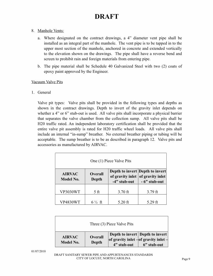
Vacuum Valve Pits
1. General
Valve pit types: Valve pits shall be provided in the following types and depths as shown in the contract drawings. Depth to invert of the gravity inlet depends on whether a 4” or 6” stub-out is used. All valve pits shall incorporate a physical barrier that separates the valve chamber from the collection sump. All valve pits shall be H20 traffic rated. An independent laboratory certification shall be provided that the entire valve pit assembly is rated for H20 traffic wheel loads. All valve pits shall include an internal “in-sump” breather. No external breather piping or tubing will be acceptable. The sump breather is to be as described in paragraph 12. Valve pits and accessories as manufactured by AIRVAC.
One (1) Piece Valve PitsOne (1) Piece Valve PitsOne (1) Piece Valve PitsOne (1) Piece Valve Pits
AIRVACModel No.
Overall Depth
Depth to invert of gravity inlet
-4” stub-out
Depth to invert of gravity inlet - 6” stub-out
VP3030WT 5 ft 3.70 ft 3.79 ft
VP4830WT 6 ½ ft 5.20 ft 5.29 ft
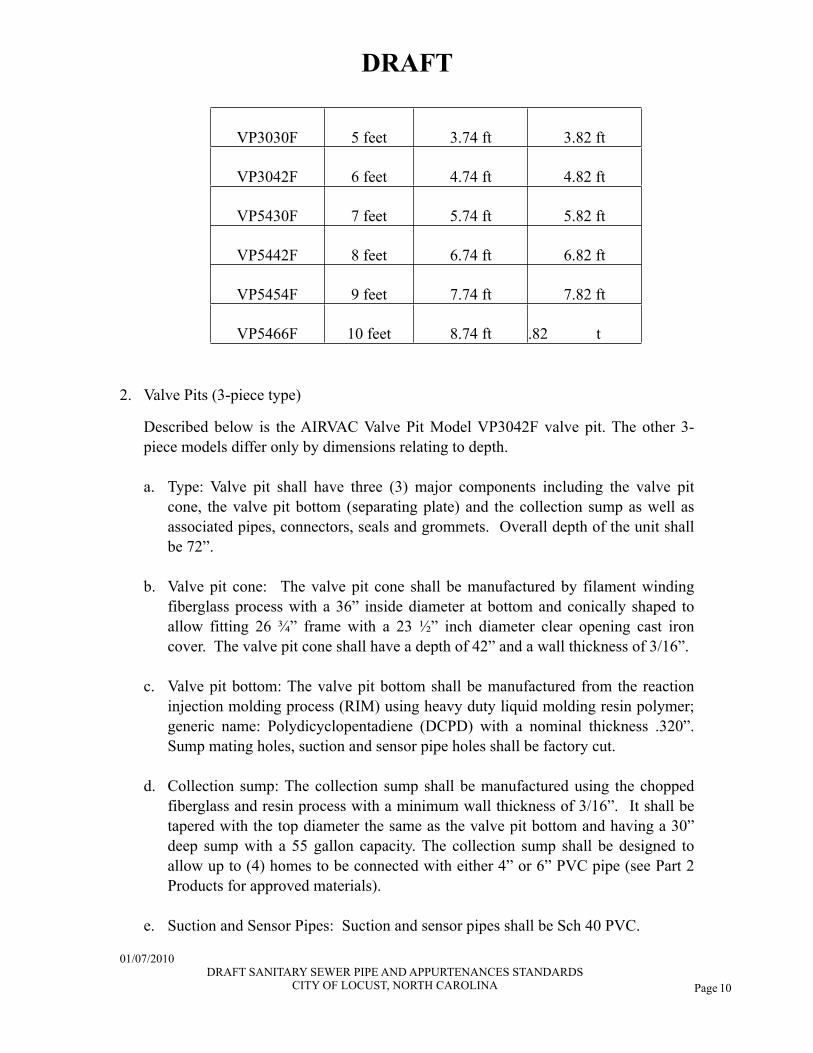
Three (3) Piece Valve PitsThree (3) Piece Valve PitsThree (3) Piece Valve PitsThree (3) Piece Valve Pits
AIRVACModel No.
Overall Depth
Depth to invert of gravity inlet –
4” stub-out
Depth to invert of gravity inlet –
6” stub-out
DRAFT
01/07/2010 DRAFT SANITARY SEWER PIPE AND APPURTENANCES STANDARDS
CITY OF LOCUST, NORTH CAROLINA
Page 10
VP3030F 5 feet 3.74 ft 3.82 ft
VP3042F 6 feet 4.74 ft 4.82 ft
VP5430F 7 feet 5.74 ft 5.82 ft
VP5442F 8 feet 6.74 ft 6.82 ft
VP5454F 9 feet 7.74 ft 7.82 ft
VP5466F 10 feet 8.74 ft .82 t
2. Valve Pits (3-piece type)
Described below is the AIRVAC Valve Pit Model VP3042F valve pit. The other 3-piece models differ only by dimensions relating to depth.
a. Type: Valve pit shall have three (3) major components including the valve pit cone, the valve pit bottom (separating plate) and the collection sump as well as associated pipes, connectors, seals and grommets. Overall depth of the unit shall be 72”.
b. Valve pit cone: The valve pit cone shall be manufactured by filament winding fiberglass process with a 36” inside diameter at bottom and conically shaped to allow fitting 26 ¾” frame with a 23 ½” inch diameter clear opening cast iron cover. The valve pit cone shall have a depth of 42” and a wall thickness of 3/16”.
c. Valve pit bottom: The valve pit bottom shall be manufactured from the reaction injection molding process (RIM) using heavy duty liquid molding resin polymer; generic name: Polydicyclopentadiene (DCPD) with a nominal thickness .320”. Sump mating holes, suction and sensor pipe holes shall be factory cut.
d. Collection sump: The collection sump shall be manufactured using the chopped fiberglass and resin process with a minimum wall thickness of 3/16”. It shall be tapered with the top diameter the same as the valve pit bottom and having a 30” deep sump with a 55 gallon capacity. The collection sump shall be designed to allow up to (4) homes to be connected with either 4” or 6” PVC pipe (see Part 2 Products for approved materials).
e. Suction and Sensor Pipes: Suction and sensor pipes shall be Sch 40 PVC.
DRAFT
01/07/2010 DRAFT SANITARY SEWER PIPE AND APPURTENANCES STANDARDS
CITY OF LOCUST, NORTH CAROLINA
Page 11
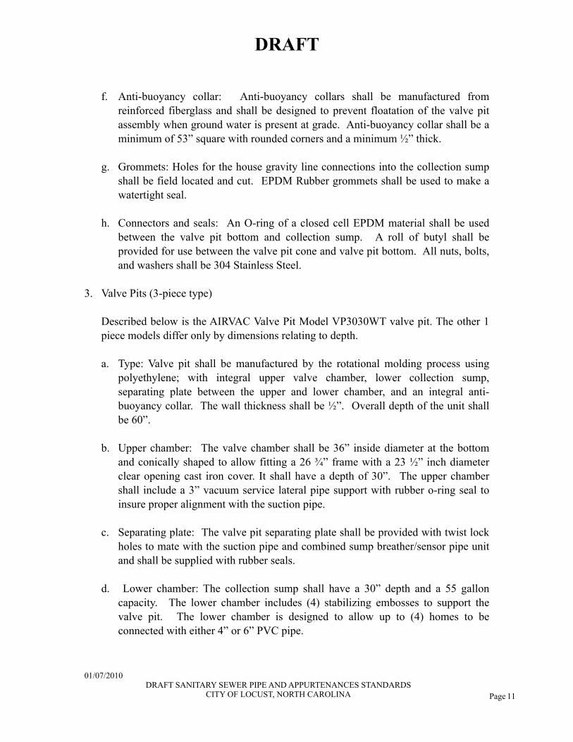
f. Anti-buoyancy collar: Anti-buoyancy collars shall be manufactured from reinforced fiberglass and shall be designed to prevent floatation of the valve pit assembly when ground water is present at grade. Anti-buoyancy collar shall be a minimum of 53” square with rounded corners and a minimum ½” thick.
g. Grommets: Holes for the house gravity line connections into the collection sump shall be field located and cut. EPDM Rubber grommets shall be used to make a watertight seal.
h. Connectors and seals: An O-ring of a closed cell EPDM material shall be used between the valve pit bottom and collection sump. A roll of butyl shall be provided for use between the valve pit cone and valve pit bottom. All nuts, bolts, and washers shall be 304 Stainless Steel.
3. Valve Pits (3-piece type)
Described below is the AIRVAC Valve Pit Model VP3030WT valve pit. The other 1 piece models differ only by dimensions relating to depth.
a. Type: Valve pit shall be manufactured by the rotational molding process using polyethylene; with integral upper valve chamber, lower collection sump, separating plate between the upper and lower chamber, and an integral anti-buoyancy collar. The wall thickness shall be ½”. Overall depth of the unit shall be 60”.
b. Upper chamber: The valve chamber shall be 36” inside diameter at the bottom and conically shaped to allow fitting a 26 ¾” frame with a 23 ½” inch diameter clear opening cast iron cover. It shall have a depth of 30”. The upper chamber shall include a 3” vacuum service lateral pipe support with rubber o-ring seal to insure proper alignment with the suction pipe.
c. Separating plate: The valve pit separating plate shall be provided with twist lock holes to mate with the suction pipe and combined sump breather/sensor pipe unit and shall be supplied with rubber seals.
d. Lower chamber: The collection sump shall have a 30” depth and a 55 gallon capacity. The lower chamber includes (4) stabilizing embosses to support the valve pit. The lower chamber is designed to allow up to (4) homes to be connected with either 4” or 6” PVC pipe.
DRAFT
01/07/2010 DRAFT SANITARY SEWER PIPE AND APPURTENANCES STANDARDS
CITY OF LOCUST, NORTH CAROLINA
Page 12
e. Suction and Sensor Pipes: The suction pipe shall be PE and have a twist lock mechanism to mate with the holes in the separating plate. The sensor pipe shall be incorporated into the sump breather which shall have a twist lock mechanism to mate with the holes in the separating plate.
f. An integral anti-buoyancy collar, made of PE, shall be provided. The anti-buoyancy collar shall be factory-installed.
g. Grommets: Holes for the house gravity line connections into the lower chamber shall be field located and cut. Rubber grommets shall be used to make a watertight seal.
4. One (1) Foot Extension
a. Extension piece: The extension piece shall be manufactured by the rotational molding process using polyethylene and allow fitting a 26 ¾” frame with a 23 ½” inch diameter clear opening cast iron cover. It shall have a depth of 12”.
b. Mating gasket: The 1’ extension shall include a mating gasket located between the upper chamber of the 5’ pit and the 1’ extension piece.
c. Manufacturer: Extension piece AP2600 and gasket AP2045 as manufactured by AIRVAC.
5. Flexible Connector
Flexible connector: Flexible connector shall be 3” in diameter with an overall length of 7’10 ¼” (+/-3/4”)”. The flexible connector shall incorporate a 4’ 2” long piece of flexible pipe that is specially manufactured for AIRVAC. The flexible pipe shall have the proper outside diameter for solvent welding into PVC fittings. One end of the flexible pipe shall be joined to a piece of 3” Sch. 40 PVC pipe with a 3” Sch. 40 PVC coupling. The opposite end of the flexible pipe shall be fitted with a 3” Sch. 40 PVC coupling. Flexible connectors shall be as manufactured by AIRVAC.
6. Valve Pit Covers
a. Valve pit covers: Valve pit covers shall be designed for H-20 loading. Castings shall meet ASTM A-48, Class 30 gray cast iron.
b. Identification markings: The words "AIRVAC SEWER" shall appear on top of cover in 1” tall lettering.
DRAFT
01/07/2010 DRAFT SANITARY SEWER PIPE AND APPURTENANCES STANDARDS
CITY OF LOCUST, NORTH CAROLINA
Page 13
c. Pick holes: Covers for the one-piece valve pit shall have elastomer seals and a concealed pick hole. Covers for the three-piece valve pit shall have an open pick hole and no elastomer seal.
d. Concrete collars: Concrete collars are required for all AIRVAC valve pits located in traffic areas. See Engineer’s drawings and/or specifications for definition of ‘traffic areas’ as well as the design details of the collar.
e. Manufacturer: Model R5900 by Neenah Foundry or equal.
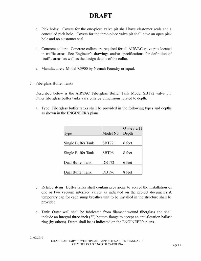
7. Fiberglass Buffer Tanks
Described below is the AIRVAC Fiberglass Buffer Tank Model SBT72 valve pit. Other fiberglass buffer tanks vary only by dimensions related to depth.
a. Type: Fiberglass buffer tanks shall be provided in the following types and depths as shown in the ENGINEER’s plans.
Type Model No.O v e r a l l Depth
Single Buffer Tank SBT72 6 feet
Single Buffer Tank SBT96 8 feet
Dual Buffer Tank DBT72 6 feet
Dual Buffer Tank DBT96 8 feet
b. Related items: Buffer tanks shall contain provisions to accept the installation of one or two vacuum interface valves as indicated on the project documents A temporary cap for each sump breather unit to be installed in the structure shall be provided.
c. Tank: Outer wall shall be fabricated from filament wound fiberglass and shall include an integral three-inch (3”) bottom flange to accept an anti-flotation ballast ring (by others). Depth shall be as indicated on the ENGINEER’s plans.
DRAFT
01/07/2010 DRAFT SANITARY SEWER PIPE AND APPURTENANCES STANDARDS
CITY OF LOCUST, NORTH CAROLINA
Page 14
d. Sump/valve chamber divider: A gas tight removable divider to separate an upper valve pit area from the lower sewage collection sump shall be provided. Divider shall be factory drilled and fitted with grommets for suction pipe assemblies, sensor/clean-out assemblies, and sump breather units.
e. Collection sump: The collection sump shall contain an integral basin for each vacuum valve installed in the structure. Basin design shall be such that each valve cycle will remove approximately 10 gallons of liquid. Dual valve buffer tanks shall include provisions to divide flow between the two collection sump basins.
a. Service lateral: A 3” Sch 40 or SDR 21 PVC service lateral, 6’ long, shall be installed through the wall of the tank and a flexible service connector assembly shall be provided (one of each for a SBT; 2 of each for a DBT).
b. Gravity stub-out pipe: A single 6” PVC gravity sewer pipe, 6’ long (see Part 2 Products for approved materials) shall be installed through the tank wall for connection in the field by the CONTRACTOR.
c. Suction and sensor pipes: (one of each required for each vacuum valve).
d. Grommets: Vacuum system manufacturer shall provide an elastomeric seal/grommet for each pipe passing through the valve pit, valve pit bottom and sump to provide a seal against ground water without the use of threaded fasteners.
e. Cover: Structure shall be fitted with a 48” 304 Stainless steel cover that includes a hinged access door with hasp for padlock.
8. Concrete Buffer Tanks
a. Tank: A 48” diameter, reinforced pre-cast concrete manhole sections with integral base shall be provided, containing a bottom sump as shown on the standard details.
b. Manhole Joints: Joints shall be tongue and groove in pre-cast wall; pre-formed flexible plastic gaskets, Type 1, rope form, which meet or exceed FS-SS-S-00210.
c. Manhole steps: Steps shall be located as shown on the standard details and shall be aligned vertically and spaced uniformly 16 inches apart. Steps shall be firmly embedded into sidewalls of the buffer tank. Step material shall be 304 Stainless Steel.
DRAFT
01/07/2010 DRAFT SANITARY SEWER PIPE AND APPURTENANCES STANDARDS
CITY OF LOCUST, NORTH CAROLINA
Page 15
d. Collections sumps: The sump shall be 1'-6" in diameter and 1'-0" deep. The bottom of the tank shall be sloped from the gravity inlets toward the sump as shown on the standard details. Dual valve buffer tanks shall include provisions to divide flow between the two collection sump basins.
e. Pipe penetrations: All pipe penetrations through the buffer tank walls shall be watertight. Contractor to submit material to be used for sealing to the Engineer.
f. Cover: Manhole casting and frame, with concealed pick holes and gasket. Cover to be clear, even grain, tough, gray cast iron, smooth, true to pattern and free of projections, sand holes, warp and other defect; designed for H2O traffic loading; Class 30 Gray Iron; ASTM A48. Model R5900 Neenah Foundry or equal.
g. Related items: Buffer tanks shall contain provisions to accept the installation of one or two AIRVAC vacuum interface valves as indicated on the project drawings. The vacuum valves are to be as described in Paragraphs 2.13 and 2.14, with the exception that they are Type “D”, intended for use with external breathers.
h. Accessories: Buffer Tank Kits are to be supplied by AIRVAC and shall include the flexible breather and all fittings except the underground piping or tubing. The kit shall also include the internal piping supports, tubing, tubing clamps, no-hub clamps and sensor cap(s). Refer to the plans for specific parts assembly
9. Vacuum Valve and Valve Pit Interdependence
a. Interdependence: The vacuum valve and valve pit shall be designed to function together as a complete system. Valve, valve pits and accessories shall be by the same manufacturer.
b. Manufacturer: Vacuum valves, valve pits and accessories as manufactured by AIRVAC.
10. Vacuum Valve
a. Design conformance: Vacuum valves shall be designed such that head loss through the valve is at minimum. The “Cv” factor for these valves shall be 268 or higher. An Independent laboratory certificate shall be supplied upon request.
b. Type: Internal breather; Type F as manufactured by AIRVAC.
DRAFT
01/07/2010 DRAFT SANITARY SEWER PIPE AND APPURTENANCES STANDARDS
CITY OF LOCUST, NORTH CAROLINA

Page 16
c. Valve Construction: Full-port 3-inch diameter valve capable of passing a 3” diameter solid while matching the outside diameter of 3” SDR 21 PVC pipe. Valve to be vacuum operated on opening and spring assisted on closing; valve configuration arranged so that the sewer vacuum ensures positive valve seating. Valve plunger and shaft arranged to be completely out of the flow path when valve is in open position.
d. Vacuum Operator: Self lubricating, rolling diaphragm type; diameter sufficient to open valve fully using line vacuum to overcome sealing force; equipped with elastomer seal where shaft enters housing; vacuum drain connected to housing to return seal leakage to sewer when valve cycles.
e. Operation: Valve and sensor / controller require no outside power service.
f. The valve shall be manufactured such that small objects may be removed from the valve seat area by means other than complete valve removal and disassembly.
g. The valve and sensor/controller shall be capable of operation when submerged in water to a depth of 2 feet above the upper most component.
h. Materials: Valves shall be chemically resistant to sewage and sewage gases. The valves shall be constructed from materials described in the following table.
COMPONENT MATERIALValve Body Glass Filled PolypropyleneValve Shaft 316 Stainless SteelValve Shaft Seal Buna N RubberValve O-Rings Buna N RubberValve Spring 304 Stainless SteelValve Plunger PolypropyleneValve Seat EPDM RubberValve Piston Cup PolypropyleneValve Bearing Acetal
i. Furnished: Vacuum valves shall be furnished by the Contractor.
j. Installed: Vacuum valves shall be installed by the City of Locust, unless approved by the Public Works Director.
DRAFT
01/07/2010 DRAFT SANITARY SEWER PIPE AND APPURTENANCES STANDARDS
CITY OF LOCUST, NORTH CAROLINA
Page 17
k. Manufacturer: Vacuum valve and accessories as manufactured by AIRVAC.
11. Vacuum Valve Sensor/Controller
a. The valve as described in paragraph 10 shall be equipped with a sensor-controller which shall rely on atmospheric air and vacuum pressure from the downstream side of the valve for its operation, thereby requiring no other power source. Rising liquid within the holding sump shall initiate the opening of the valve when sufficient head pressure is reached in the holding sump. The activation point shall equate to approximately 10 gallons of liquid. The controller shall apply line vacuum from the downstream side of the vacuum valve and apply it to the actuator chamber and fully open the valve.
b. The controller shall be capable of maintaining the valve fully open for a fixed period of time. This shall be field adjustable over a range of 3 to 10 seconds. After this time period has elapsed, the controller shall apply atmospheric air to the actuator chamber permitting spring assisted closure of the valve.
c. The controller shall be serviceable by factory-trained personnel and shall be removable from the valve by means of a sliding key device. There shall be no tools required to remove and replace the controller from the vacuum valve with the exception of tubing clamp nut drivers.
d. The entire body shall be constructed to allow visual inspection of the internal mechanism without disassembly. The controller shall be equipped with external test ports for bench testing of various chambers during re-build.
e. Each vacuum valve controller shall be equipped with a port for connecting a portable, self-contained valve cycle counter.
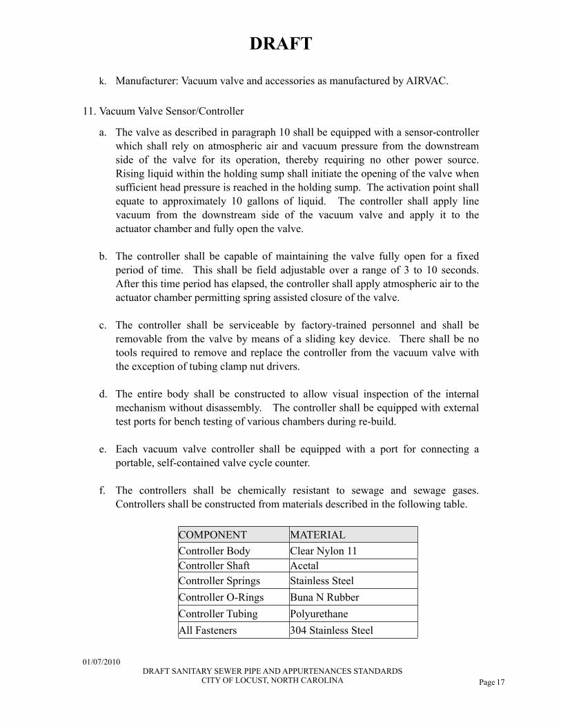
f. The controllers shall be chemically resistant to sewage and sewage gases. Controllers shall be constructed from materials described in the following table.
COMPONENT MATERIALController Body Clear Nylon 11Controller Shaft AcetalController Springs Stainless SteelController O-Rings Buna N RubberController Tubing PolyurethaneAll Fasteners 304 Stainless Steel
DRAFT
01/07/2010 DRAFT SANITARY SEWER PIPE AND APPURTENANCES STANDARDS
CITY OF LOCUST, NORTH CAROLINA
Page 18
g. Manufacturer: Vacuum valve controller as manufactured by AIRVAC.
12. In-Sump Breather
a. With the exception of the individual house 4” gravity line air intake (or the 6” Dedicated Air Terminal, if used), there shall be no other external sources of air necessary or permitted as a part of this assembly.
b. A factory provided internal sump breather unit arrangement shall connect the controller to its air source and provide a means of assuring no liquid can enter the controller during system shut downs and re-starts.
c. The internal sump breather shall be arranged to prevent sump pressure from forcing the valve to open during low vacuum conditions and provide positive sump venting regardless of traps in the home gravity service line.
d. Manufacturer: In-sump breather as manufactured by AIRVAC.
PART 3: EXECUTION
3.01 INSTALLATION
Excavation:
1. The work covered by this section consists of the excavation and satisfactory disposal of all materials excavated in the construction of trenches.
2. Trenches will be defined as all excavation for the installation of storm sewers, sanitary sewers, water pipe, manholes, catch basins, hydrants, watergates, sewer services, water taps, drainage structures, drainage ditches and other unclassified excavation as may be deemed necessary by the Engineer.
3. The excavation shall be done to the lines, grades, typical sections, and details shown on the plans or established by the Engineer. All work covered by this section shall be coordinated with the grading, construction of drainage structures, and other work along the project, and shall be maintained in a satisfactory condition so that adequate drainage is provided at all times. Any roots which protrude into the trench shall be trimmed flush with the sides of the trench. Trenches for pipe lines shall be completed before the pipe is installed unless otherwise permitted by the Engineer.
DRAFT
01/07/2010 DRAFT SANITARY SEWER PIPE AND APPURTENANCES STANDARDS
CITY OF LOCUST, NORTH CAROLINA
Page 19
4. All trenches shall be excavated in accordance with all Federal, State, and Local Health and Safety regulations having jurisdiction at the project site.
5. All excavation shall be by open cut unless otherwise authorized by the Engineer. If the bottom of the excavation is found to consist of rock or any materials that cannot be excavated to give a uniform bearing surface, the material shall be removed to a depth at least 6” below established bottom grade and backfilled to grade with sand thoroughly compacted in place. Any excavations carried below the depths indicated, without specific directions, shall be backfilled in the same manner. The excavation shall be of sufficient width to allow a clearance of not less than 6” between the side of the trench and the outside of the pipe, or in case of pipe with a bell, the outside of the bell of the pipe. This rule will apply at all times, and consequently, proper allowance must be made for additional space required for sheeting the trench where necessary.
6. Erosion control measures meeting all NCDENR Division of Land Resources requirements shall be installed and maintained at the site during construction. The Developer shall obtain an erosion and sedimentation control permit for the site when required, and shall comply with all provisions of the permit.
7. Sheeting, Bracing Trenches, and Trench Boxes:
a. If necessary, the Contractor will be required to keep the sides of the excavation vertical by sheeting and/or bracing or the use of a trench box to prevent movement by slides or settling of the sides of the trench, in such manner as to prevent injury or displacement of the pipe or appurtenances or diminish the working space required at the sides of the pipe. Also, the Contractor may be required for the purpose of preventing injury to persons or property or adjacent structures in place or to be constructed, to leave sheeting and bracing in place. Sheeting and bracing shall be provided in accordance with all applicable Federal, State and Local safety and health regulations.
b. No sheeting or bracing shall extend closer than 2’-0” off the ground surface, or within subgrade, and no timbers shall be left in the trench that may form pockets or cavities that cannot easily be filled during the operation of backfilling and settling or compacting the trench backfill. It is understood that the Owner will be under no obligation to pay for sheeting or bracing left in place by the Contractor. Failure to sheet and brace trenches or other excavation shall be the Contractor's risk, and he will be held responsible for caving, settlement, and all other damage resulting therefrom.
8. Excavated materials to be used for backfill will be approved by the Engineer and Public Works Director, and if acceptable shall be neatly deposited at the sides of the
DRAFT
01/07/2010 DRAFT SANITARY SEWER PIPE AND APPURTENANCES STANDARDS
CITY OF LOCUST, NORTH CAROLINA
Page 20
trenches where space is available. Where stockpiling of excavated material is required, the Contractor shall so maintain his operations as to provide for natural drainage and not present an unsightly appearance.
9. Pipe Foundations:
a. The preparation of the pipe bedding shall be in accordance with the typical trench crosssections as shown on the plans for the type of pipe being installed.
b. The pipe foundation shall be prepared to be uniformly firm and shall be true to the lines and grades as shown on the plans. Any deviation or field adjustment will require the approval of the Engineer and Public Works Director. When a representative of the Engineer is present on the site and is so requested by the Contractor, he may check the position of grades and lines but the Contractor shall be responsible for the finished work conforming to exact and proper line and grade.
c. Whenever the nature of the ground will permit, the excavations at the bottom of the trench shall have the shape and dimensions of the outside lower third of the circumference of the pipe, care being taken to secure a firm bearing support uniformly throughout the length of the pipe. A space shall be excavated under and around each bell to sufficient depth to relieve it of any load and to allow ample space for filling and finishing the joint. The pipe, when thus bedded firmly, shall be on the exact grade.
d. In case the bed shaped in the bottom of the trench is too low, the pipe shall be completely removed from position, and earth of suitable quality shall be placed and thoroughly tamped to prepare a new foundation for the pipe. In no case shall the pipe be brought to grade by blocking up under the barrel or bell of same, but a new and uniform support must be provided for the full length of the pipe.
e. Where rock or boulders are encountered in the bottom of the trench, the same shall be removed to such depth that no part of the pipe, when laid to grade, will be closer to the rock or boulders than 6”. A suitably tamped and shaped foundation of approved material shall be placed to bring the bottom of the trench to proper subgrade over rock or boulders.
f. Where the foundation material is found to be of poor supporting value, the Engineer may make minor adjustment in the location of the pipe to provide a more suitable foundation. Where this is not practical, the foundation shall be conditioned by removing the existing foundation material by undercutting to the depth as directed by the Engineer, within limits established on the plans, and
DRAFT
01/07/2010 DRAFT SANITARY SEWER PIPE AND APPURTENANCES STANDARDS
CITY OF LOCUST, NORTH CAROLINA
Page 21
backfilling with either an approved material secured from unclassified excavation or borrow excavation at the nearest accessible location along the project, or foundation conditioning material consisting of crushed stone or gravel approved by the Engineer as being suitable for the purpose intended. The selection of the type of backfill material to be used for foundation conditioning will be made by the Engineer.
g. The Contractor shall remove all water which may be encountered or which may accumulate in the trenches by pumping or bailing and no pipes shall be laid until the water has been removed from the trench. Water so removed from the trench must be disposed of in such a manner as not to cause injury to work completed or in progress.
h. Whenever the bottom of the trench shall be of such nature as to provide unsatisfactory foundation for the pipe, the Engineer will require the pipe to be laid on a washed stone foundation per detail. Foundation stone shall be placed by the Contractor, as required. Class I embedment for DIP shall be used only for wet conditions and only as directed by the Engineer.
Installing Pipe and Appurtenances:
1. Laying Pipe:
a. The layout of gravity sanitary sewer lines and invert elevations at governing points are as shown on the drawings.
b. The Contractor shall do all layout work for lines and grades from that information shown on the drawings or as furnished by the Engineer.
c. When a laser beam instrument is used to set line and grade, the unit must be maintained in good working order, and the calibration checked daily for both alignment and percent grade. In the event the required accuracy of alignment and grade is not adhered to, the Engineer will prohibit the use of laser beams.
d. Pipe shall be laid with bell ends facing in the direction of pipe laying, unless directed otherwise by the Engineer. In all cases, pipe is to be installed in strict accordance with the manufacturer's recommendations and the contract material specifications. The Engineer may augment any manufacturer's installation recommendations if, in his opinion, it will best serve the interest of the Owner.
e. Proper tools, implements, and facilities satisfactory to the Engineer shall be provided and used for the safe and convenient prosecution of pipe laying. All
DRAFT
01/07/2010 DRAFT SANITARY SEWER PIPE AND APPURTENANCES STANDARDS
CITY OF LOCUST, NORTH CAROLINA
Page 22
pipe and other materials used in the laying of pipe will be lowered into the trench piece by piece by means of suitable equipment in such a manner to prevent damage to the pipe, materials, to the protective coating on the pipe materials, and to provide a safe working condition to all personnel in the trench. Each piece of pipe being lowered into the trench shall be clean, sound and free from defects. It shall be laid on the prepared foundation, as specified elsewhere to produce a straight line on a uniform grade, each pipe being laid so as to form a smooth and straight inside flow line. Pipe shall be removed at any time if broken, injured or displaced in the process of laying same, or of backfilling the trench.
f. When cutting short lengths of pipe, a pipe cutter, as approved by the Engineer, will be used and care will be taken to make the cut at right angles to the centerline of the pipe or on the exact skew as shown on the plans. In the case of pushon pipe, the cut ends shall be tapered with a portable grinder, or coarse file to match the manufactured taper.
g. During times when pipe laying is not in progress, the open ends of pipe shall be closed and no trench water or other material shall be permitted to enter the pipe.
h. Where the pipe is laid on a grade of 20% or greater, the laying shall start at the bottom of the slope and proceed upward with the bell end of the new pipe upgrade. All pipe laid on a grade of 20% or greater shall require thrust blocking or keying as shown on the drawings and standard details.
i. Where pipe lines of different materials are joined together, a standard sewer repair coupling shall be used. The couplings shall be Eastern Standard Sewer Repair Couplings (Mission Rubber Company), the Fernco Joint Sealer Company or an equal product approved by the Engineer and Public Works Director.
j. All gravity sewer shall have minimum 24” vertical separation from storm sewer and shall have minimum 10’-0” horizontal separation from water mains or 18” vertical separation below the bottom of the water main. In the event these separations cannot be met, sanitary sewer and the water main, if applicable, shall be constructed of ductile iron pipe as directed by the Engineer or as shown on the drawings. In addition, all gravity sewer shall have a minimum 100’-0”, horizontal separation from wells or other water supplies.
2. Manholes:
a. Sanitary sewer manholes shall be installed at each break in line or grade in each sanitary sewer line as shown on the contract drawings.
DRAFT
01/07/2010 DRAFT SANITARY SEWER PIPE AND APPURTENANCES STANDARDS
CITY OF LOCUST, NORTH CAROLINA
Page 23
b. The manhole foundation shall be prepared so as to provide a firm, level area on which to place the precast concrete manhole base section. When poor foundation soil is encountered or excess groundwater exists, the foundation shall be excavated 12” below the final subgrade elevation backfilled with washed stone to provide a proper foundation.
c. The manhole sections shall be lifted from the side of the excavation to the bottom of the trench with equipment and support slings capable of safely handling the heavy concrete pieces. The manhole shall be set plumb and adjusted to the final finished surface grade with precast concrete grade rings.
d. Pipe openings shall be exactly aligned to that of the pipe entering and leaving the manhole. The gravity sanitary sewer pipe lines shall be placed in the manhole openings, properly aligned, and set to grade. Sanitary sewer shall be connected to the manholes using lock joint flexible manhole sleeves or equal.
e. For large diameter pipe where a flexible rubber sleeve is not available, the pipe line shall be sealed into the manhole using an expanding type or nonshrink type grout.
f. For manhole steps, refer to the precast manhole section above.
3. Manhole Frames and Covers: The frame and cover shall be properly set in a bed of mortar and aligned to fit the top section of the manhole. Precast concrete grade rings, set in mortar, shall be used to adjust the top of the frame and cover to finished grade; however, no more than three (3) rings be used for adjustment. All covers and grade rings shall be anchored to the manhole cone with stainless steel anchor bolts.
4. Manhole Inverts:
a. Manhole inverts and benches shall be constructed in accordance with the standard details shown on the drawings. Invert shall be a Ushaped channel with a height of 0.8 of the diameter and be a smooth continuation of the pipe. The benches shall be constructed with a slope of 1” per foot to the channel.
b. The channel and invert shall be constructed with a minimum of 2000 psi concrete or brick fill with concrete finish minimum 1” thick. Where sewer changes directions at the manhole, channel shall be constructed with a smooth curve with as large a radius as the diameter of the manhole will allow.
DRAFT
01/07/2010 DRAFT SANITARY SEWER PIPE AND APPURTENANCES STANDARDS
CITY OF LOCUST, NORTH CAROLINA
Page 24
5. Manhole Drops: Standard drop manholes will be constructed only at those locations shown on the drawings or as approved by the Engineer. The design of the drop connection shall be in accordance with the standard detail drawing.
6. Manhole Vents:
a. Where designated on the contract drawings, a 4” diameter vent pipe shall be installed as an integral part of the manhole. The vent pipe is to be tapped in to the upper most section of the manhole, anchored in concrete and extended vertically to the elevation shown on the drawings. The pipe shall have a reverse bend and screen to prohibit rain and foreign materials from entering pipe.
b. The pipe material shall be Schedule 40 Galvanized Steel with two coats of epoxy paint approved by the Engineer.
7. Fittings (Force Main):
a. All plugs, caps, tees, bends, and other fittings shall be provided with adequate thrust blocks. Thrust blocks shall be constructed to the minimum dimensions shown on the drawings or as directed. Thrust blocks shall be made of concrete and shall bear directly against the undisturbed trench wall. Where possible, the backing shall be so placed that the fitting joints will be accessible for repair. All bolts and pipe joints shall be protected against contact with thrust block concrete by the installation of a polyethylene film placed between the fittings and the poured concrete. Where any section of a main is provided with concrete thrust blocks, the hydrostatic pressure test shall not be made until three days after installation of the concrete thrust blocks unless otherwise approved by the Engineer.
b. Where trench conditions are, in the opinion of the Engineer, unsuitable for thrust blocks, the Contractor shall provide steel tie rods and socket clamps to adequately anchor the piping. All tie rods and clamps shall be given a bituminous protective coating or shall be galvanized.
c. Concrete for thrust blocks shall consist of a mix of Portland Cement, fine and coarse aggregate and water to produce concrete with a minimum compressive strength at 28 days of not less than 3000 psi when tested in accordance with ASTM Specifications C 39 or C 42. Sakrete or any similar material will not be permitted under any circumstances.
8. Gate Valve and Valve Box (Force Main):
DRAFT
01/07/2010 DRAFT SANITARY SEWER PIPE AND APPURTENANCES STANDARDS
CITY OF LOCUST, NORTH CAROLINA
Page 25
a. When shown on the contract drawings, a standard gate valve shall be installed in the sanitary sewer force main. Before setting each valve, the Contractor shall make sure the interior is clean and shall test the valve for proper opening and closing. Valves shall be set with stems plumb, unless horizontal installation is called for on the drawings, and at the exact location(s) shown on the drawings.
b. A standard type valve box shall be installed over each underground sanitary sewer force main valve. All valve boxes shall be set plumb with their top set flush with the finished grade.
c. Trench backfill shall be properly tamped for a distance of 3’-0” on each side of the valve and valve box.
9. Sewage Combination Air Relief Valve (Force Main):
a. A sanitary sewage combination air relief valve shall be installed at the locations shown on the contract drawings and the actual high points in the line.
b. A combination air relief valve installation, as shown in detail in the contract drawings, shall consist of the force main tap, air relief valve, precast concrete manhole sections, and standard heavy duty iron frame and cover.
10. Exposed Pipe:
a. Exposed pipe to be installed inside tanks, wetwells, vaults and buildings shall be installed as shown on the Drawings and field painted as described below. All exposed ductile iron pipe shall utilize flanged joints unless otherwise noted.
b. All exposed cast or ductile iron pipe, fittings and valves shall be field painted with two (2) coats of epoxy paint as recommended by the paint manufacturer. Color of paint shall be as selected by the City of Locust.
11. Valve Pits - General:
a. The end of the stub-out pipe that passes through the valve pit grommet shall be beveled. A stop ring shall be used to ensure the pipe does not protrude more than 4” inside the collection sump with an allowable tolerance of ± 1/8”.
b. All pipes that penetrate the valve pit through grommets shall be as described in Part 2 “Products”. No other pipe is acceptable.
c. Water-soluble soap shall be used when installing PVC pipes through AIRVAC grommets. Use of petroleum lubricant or pipe lube is prohibited.
DRAFT
01/07/2010 DRAFT SANITARY SEWER PIPE AND APPURTENANCES STANDARDS
CITY OF LOCUST, NORTH CAROLINA
Page 26
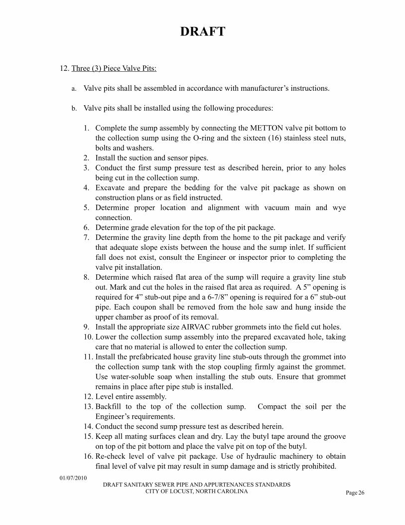
12. Three (3) Piece Valve Pits:
a. Valve pits shall be assembled in accordance with manufacturer’s instructions.
b. Valve pits shall be installed using the following procedures:
1. Complete the sump assembly by connecting the METTON valve pit bottom to the collection sump using the O-ring and the sixteen (16) stainless steel nuts, bolts and washers.
2. Install the suction and sensor pipes.3. Conduct the first sump pressure test as described herein, prior to any holes
being cut in the collection sump.4. Excavate and prepare the bedding for the valve pit package as shown on
construction plans or as field instructed.5. Determine proper location and alignment with vacuum main and wye
connection.6. Determine grade elevation for the top of the pit package.7. Determine the gravity line depth from the home to the pit package and verify
that adequate slope exists between the house and the sump inlet. If sufficient fall does not exist, consult the Engineer or inspector prior to completing the valve pit installation.
8. Determine which raised flat area of the sump will require a gravity line stub out. Mark and cut the holes in the raised flat area as required. A 5” opening is required for 4” stub-out pipe and a 6-7/8” opening is required for a 6” stub-out pipe. Each coupon shall be removed from the hole saw and hung inside the upper chamber as proof of its removal.
9. Install the appropriate size AIRVAC rubber grommets into the field cut holes.10. Lower the collection sump assembly into the prepared excavated hole, taking
care that no material is allowed to enter the collection sump.11. Install the prefabricated house gravity line stub-outs through the grommet into
the collection sump tank with the stop coupling firmly against the grommet. Use water-soluble soap when installing the stub outs. Ensure that grommet remains in place after pipe stub is installed.
12. Level entire assembly.13. Backfill to the top of the collection sump. Compact the soil per the
Engineer’s requirements.14. Conduct the second sump pressure test as described herein.15. Keep all mating surfaces clean and dry. Lay the butyl tape around the groove
on top of the pit bottom and place the valve pit on top of the butyl. 16. Re-check level of valve pit package. Use of hydraulic machinery to obtain
final level of valve pit may result in sump damage and is strictly prohibited.
DRAFT
01/07/2010 DRAFT SANITARY SEWER PIPE AND APPURTENANCES STANDARDS
CITY OF LOCUST, NORTH CAROLINA
Page 27
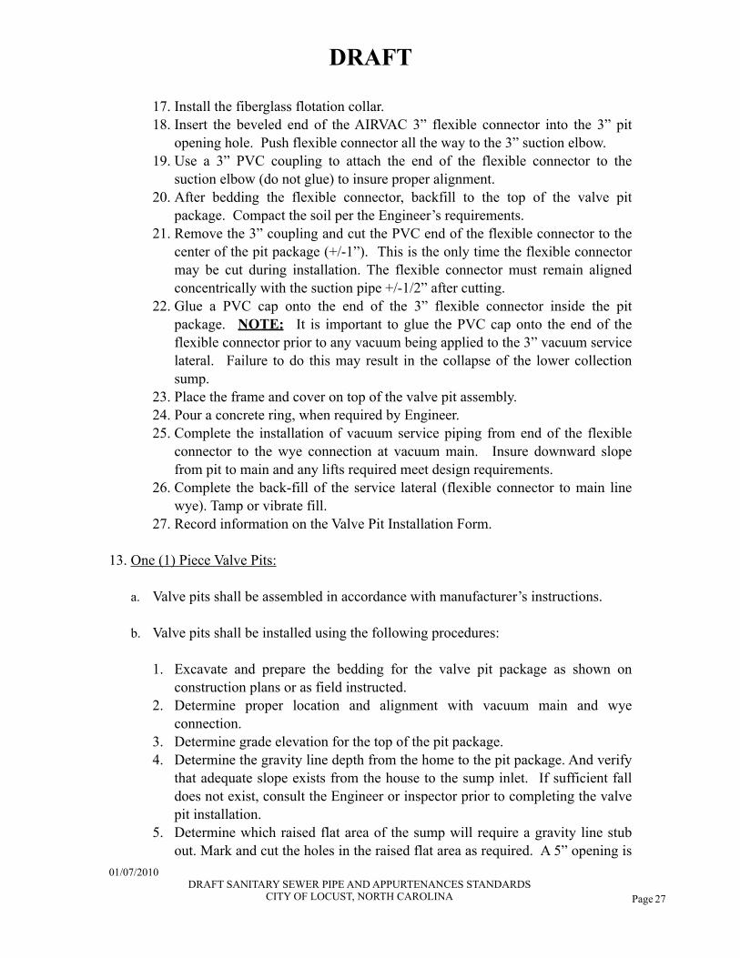
17. Install the fiberglass flotation collar.18. Insert the beveled end of the AIRVAC 3” flexible connector into the 3” pit
opening hole. Push flexible connector all the way to the 3” suction elbow.19. Use a 3” PVC coupling to attach the end of the flexible connector to the
suction elbow (do not glue) to insure proper alignment. 20. After bedding the flexible connector, backfill to the top of the valve pit
package. Compact the soil per the Engineer’s requirements.21. Remove the 3” coupling and cut the PVC end of the flexible connector to the
center of the pit package (+/-1”). This is the only time the flexible connector may be cut during installation. The flexible connector must remain aligned concentrically with the suction pipe +/-1/2” after cutting.
22. Glue a PVC cap onto the end of the 3” flexible connector inside the pit package. NOTE: It is important to glue the PVC cap onto the end of the flexible connector prior to any vacuum being applied to the 3” vacuum service lateral. Failure to do this may result in the collapse of the lower collection sump.
23. Place the frame and cover on top of the valve pit assembly.24. Pour a concrete ring, when required by Engineer.25. Complete the installation of vacuum service piping from end of the flexible
connector to the wye connection at vacuum main. Insure downward slope from pit to main and any lifts required meet design requirements.
26. Complete the back-fill of the service lateral (flexible connector to main line wye). Tamp or vibrate fill.
27. Record information on the Valve Pit Installation Form.
13. One (1) Piece Valve Pits:
a. Valve pits shall be assembled in accordance with manufacturer’s instructions.
b. Valve pits shall be installed using the following procedures:
1. Excavate and prepare the bedding for the valve pit package as shown on construction plans or as field instructed.
2. Determine proper location and alignment with vacuum main and wye connection.
3. Determine grade elevation for the top of the pit package.4. Determine the gravity line depth from the home to the pit package. And verify
that adequate slope exists from the house to the sump inlet. If sufficient fall does not exist, consult the Engineer or inspector prior to completing the valve pit installation.
5. Determine which raised flat area of the sump will require a gravity line stub out. Mark and cut the holes in the raised flat area as required. A 5” opening is
DRAFT
01/07/2010 DRAFT SANITARY SEWER PIPE AND APPURTENANCES STANDARDS
CITY OF LOCUST, NORTH CAROLINA
Page 28
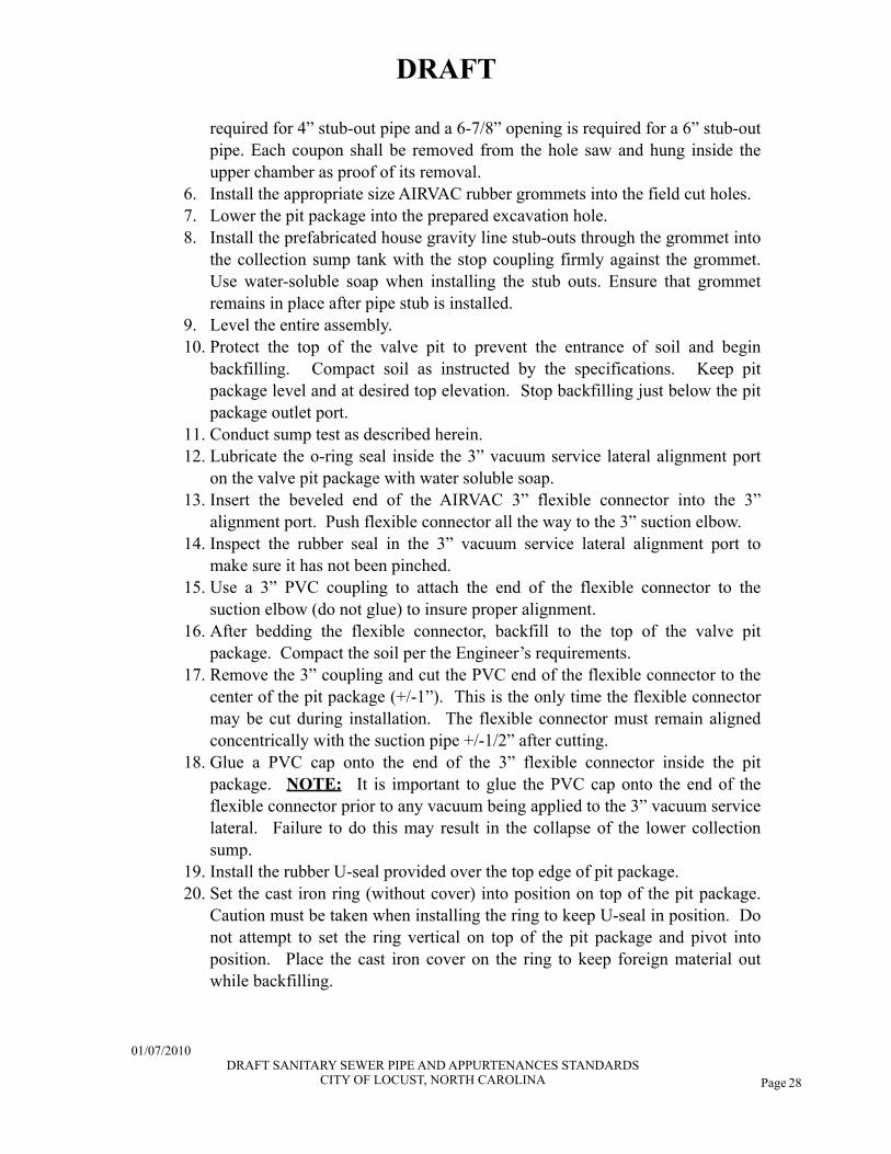
required for 4” stub-out pipe and a 6-7/8” opening is required for a 6” stub-out pipe. Each coupon shall be removed from the hole saw and hung inside the upper chamber as proof of its removal.
6. Install the appropriate size AIRVAC rubber grommets into the field cut holes. 7. Lower the pit package into the prepared excavation hole.8. Install the prefabricated house gravity line stub-outs through the grommet into
the collection sump tank with the stop coupling firmly against the grommet. Use water-soluble soap when installing the stub outs. Ensure that grommet remains in place after pipe stub is installed.
9. Level the entire assembly.10. Protect the top of the valve pit to prevent the entrance of soil and begin
backfilling. Compact soil as instructed by the specifications. Keep pit package level and at desired top elevation. Stop backfilling just below the pit package outlet port.
11. Conduct sump test as described herein.12. Lubricate the o-ring seal inside the 3” vacuum service lateral alignment port
on the valve pit package with water soluble soap.13. Insert the beveled end of the AIRVAC 3” flexible connector into the 3”
alignment port. Push flexible connector all the way to the 3” suction elbow.14. Inspect the rubber seal in the 3” vacuum service lateral alignment port to
make sure it has not been pinched.15. Use a 3” PVC coupling to attach the end of the flexible connector to the
suction elbow (do not glue) to insure proper alignment.16. After bedding the flexible connector, backfill to the top of the valve pit
package. Compact the soil per the Engineer’s requirements.17. Remove the 3” coupling and cut the PVC end of the flexible connector to the
center of the pit package (+/-1”). This is the only time the flexible connector may be cut during installation. The flexible connector must remain aligned concentrically with the suction pipe +/-1/2” after cutting.
18. Glue a PVC cap onto the end of the 3” flexible connector inside the pit package. NOTE: It is important to glue the PVC cap onto the end of the flexible connector prior to any vacuum being applied to the 3” vacuum service lateral. Failure to do this may result in the collapse of the lower collection sump.
19. Install the rubber U-seal provided over the top edge of pit package.20. Set the cast iron ring (without cover) into position on top of the pit package.
Caution must be taken when installing the ring to keep U-seal in position. Do not attempt to set the ring vertical on top of the pit package and pivot into position. Place the cast iron cover on the ring to keep foreign material out while backfilling.
DRAFT
01/07/2010 DRAFT SANITARY SEWER PIPE AND APPURTENANCES STANDARDS
CITY OF LOCUST, NORTH CAROLINA
Page 29
21. Complete the installation of vacuum service piping from flexible service lateral to wye connection at vacuum main. Insure downward slope from pit to main and any lifts required meet design requirements.
22. Complete the back-fill of the service lateral (flexible connector to main line wye). Tamp or vibrate fill.
23. Pour a concrete ring, when required by Engineer.24. Record information on the Valve Pit Installation Form.
DRAFT
01/07/2010 DRAFT SANITARY SEWER PIPE AND APPURTENANCES STANDARDS
CITY OF LOCUST, NORTH CAROLINA
Page 30
14. Fiberglass Buffer Tanks
a. Install buffer tank as shown on drawings and applicable portion of the project specifications.
b. Verify that adequate slope exists between the building drain and the buffer tank sump inlet. If buffer tank location does not allow sufficient fall to intercept building drain, advise Engineer and manufacturer’s project representative before proceeding.
c. Excavate and prepare bedding for buffer tank as shown on construction plans or as field instructed.
d. Open buffer tank access lid and verify presence of factory installed and tested sensor/clean-out assembly, suction pipe assembly, and temporary pipe plug in the sump breather grommet for each vacuum valve to be installed in the structure.
e. Lower the assembled buffer tank into the excavation.
f. Level the buffer tank.
g. Install concrete anti-buoyancy ring as per manufacturer’s instructions.
h. Backfill in accordance with project specifications.
i. Cap or seal the service lateral assembly. Must remain sealed until the vacuum valve is installed.
j. Install the sump breather unit/s and vacuum valve/s supplied by vacuum system manufacturer after final system testing and the air intake piping has been installed.
15. Concrete Buffer Tanks
a. Install buffer tank as shown on Drawings and applicable portion of the specification.
b. Fabricate and install the suction and sensor pipes as shown on the plans. Attach these lines to the buffer tank sidewalls using Aickinstrut Polyurethane channels and pipe clamps. Secure the channels using Stainless Steel anchor bolts.
DRAFT
01/07/2010 DRAFT SANITARY SEWER PIPE AND APPURTENANCES STANDARDS
CITY OF LOCUST, NORTH CAROLINA
Page 31
c. The 3" service lateral is to be stubbed into the buffer tank and capped or otherwise sealed until the vacuum valve is installed.
d. The following describes a typical installation procedure for external breathers as utilized with AIRVAC valves and may duplicate portions of AIRVAC’s installation instructions described elsewhere:
1. Mark and cut the buffer tank wall as required for the underground portion of the breather assembly. The hole is to be located at least 2” above the 5/8” breather port on the AIRVAC controller. For best results, avoid placing the opening directly behind the AIRVAC valve. The preferred location is 45º either side of the valve.
2. Install breather unit as shown on the construction drawings or as directed. It is important that the breather line connecting the valve pit to the flexible breather assembly be laid at a uniform slope towards the valve pit and that no sags be allowed in this line. Insure all buffer tanks wall penetrations are sealed.
3. Provide temporary plugs for any portion of the breather assembly not otherwise sealed for the entire construction period.
Backfilling and Compaction:
1. Backfill trenches immediately after approval of the pipeline construction.
2. Pipes:
a. PVC pipe shall be installed using Class I embedment for 6” below the pipe and to the spring line per the standard detail. Class I embedment shall be defined as #67 washed stone or approved equal per NCDOT Standard Specifications.
b. For DIP pipe with backfill material other than Class I embedment, use backfill carefully placed in uniform layers not exceeding 6” in thickness to a depth of 2’-0” over the top of the pipe. Place material and fill the area under the pipe haunches. Place each layer, moisten; then uniformly compact by use of hand, pneumatic, or mechanical tampers exercising care to prevent lateral displacement. Areas of backfill 2’-0” over top of pipe to top of trench, shall be backfilled with a material containing no rocks larger than 6” in the greatest dimension and shall be free of material with an exceptionally high void content. The initial backfill shall meet the same requirements except no rocks over 4” in diameter will be allowed.
DRAFT
01/07/2010 DRAFT SANITARY SEWER PIPE AND APPURTENANCES STANDARDS
CITY OF LOCUST, NORTH CAROLINA

Page 32
c. Moisten backfill above 2’-0” over the top of the pipe and place in 8” layers. Compact each layer with hand, pneumatic or mechanical compactor. Puddling or flooding of trench for consolidation of backfill or use of wheel rolling by construction equipment will not be permitted.
d. Foundation stone as required for wet or unstable conditions per the details, shall be defined as #57 or #67 stone per NCDOT Standard Specifications or approved equal. Foundation stone shall be used only as directed by the Engineer.
3. If material excavated from the trench is unsuitable to be used as backfill, “select backfill” shall be transported to the site by the Contractor from outside the project limits to be used as backfill material. Material excavated in conjunction with the construction of the project is not considered “select backfill” for payment purposes.
4. Roadways and Road Crossings: Use backfill placed in uniform layers not exceeding 6” in thickness for full trench depth and width, thoroughly compacted with mechanical tampers under optimum moisture conditions to 95% compaction (100% for the top 2’-0” of subgrade beneath pavements). Replace removed paving and base course with new material of equal or better quality and of the same texture and color as the adjacent roadway.
5. All backfill shall be compacted so as not to damage the pipe and appurtenances and shall be compacted to 95% of the Standard Proctor Test (100% for the top 2’-0” of subgrade beneath pavements) for the various types of backfill material. Methods of backfilling shall be in strict accordance with the pipe manufacturer's recommendations. All backfill material shall have been approved by the Engineer. Select backfill material shall be used when requested by the Engineer.
6. Care shall be taken during backfill and compaction operations to maintain alignment
and prevent damage to the joints. The backfill shall be kept free from stones, frozen lumps, chunks of highly plastic clay, or other objectionable material. All pipe backfill areas shall be graded and maintained in such a condition that erosion or saturation will not damage the pipe bed or backfill.
7. Heavy equipment shall not be operated over any pipe until it has been properly backfilled and has a minimum cover as required by the plans. Where any part of the required cover is above the proposed finish grade, the City shall place, maintain, and finally remove such material at no cost to the Owner. Pipe which becomes mis-aligned, shows excessive settlement, or has been otherwise damaged by the Contractor's operations, shall be removed and replaced by the Contractor at no cost to the City.
DRAFT
01/07/2010 DRAFT SANITARY SEWER PIPE AND APPURTENANCES STANDARDS
CITY OF LOCUST, NORTH CAROLINA
Page 33
8. The Contractor shall maintain all pipes installed in a condition that they will function continuously from the time the pipe is installed until the project is accepted.
9. Cleanup:
a.Grade all areas disturbed to a finish ordinarily obtained from a blade grader with no abrupt changes in grade or irregularities that will hold water. Prior to final inspection and acceptance, remove all rubbish and excess material and leave area in a neat, satisfactory condition.
b.Cleanup and seeding is part of the pipeline installation. No more than 3,000 LF of sewer line may be laid prior to completion of cleanup of the first section of pipeline laid.
3.02 QUALITY CONTROL
Testing:
1. Line Cleaning:
a. Prior to inspection of any section(s) of gravity sanitary sewer pipe or force main, the Contractor shall completely clean the lines and manholes of all debris, silt, etc. The Contractor shall protect the downsteam sewers. The pipe line shall be ready for use by the City and shall be proved to be in first class condition and constructed properly in accordance with the drawings and specifications,
b. The Contractor shall maintain the project, insofar as his construction work is concerned, in first class condition for such time as is necessary to satisfy the Engineer and Public Works Director that all installations are correct and acceptable.
2. Inspection and Testing (Gravity Sewer):
a. Alignment and grade between manholes shall be tested by the Engineer and Public Works Director by flashing a light between manholes. A full circle of light shall be seen when reviewed from the adjoining end of the line. All defects disclosed as a result of this test shall be corrected by the Contractor at his expense.
b. PVC pipe shall pass a gono go Mandrel sized to 95% of the pipe diameter with the pipe in place and properly backfilled. All pipe which will not pass the Mandrel shall be relaid or replaced by the Contractor at no additional cost. The allowable
DRAFT
01/07/2010 DRAFT SANITARY SEWER PIPE AND APPURTENANCES STANDARDS
CITY OF LOCUST, NORTH CAROLINA
Page 34
deflection (less than 5%) shall be calculated using the pipe stiffness formula in ASTM D 2321. The mandrel test shall not take place until the final backfill has been in place for 30 days (minimum).
c. When the sewers are completed they shall be inspected by the Engineer and Public Works Director for conformance with the provisions of the plans and specifications, particularly line and grade, and tested to determine the amount of ground water infiltration into the sewer. All visible and audible leaks will be stopped and the remaining infiltration will be measured using a Vnotch weir and/or other devices, which shall be furnished by the Contractor. The Contractor shall also furnish all required assistance for measuring the infiltration.
d. If infiltration into the whole system or any segment thereof exceeds 50 gallons per 24 hours per inch of diameter per mile of sewer, necessary corrective measures shall be taken by the Contractor to limit the infiltration to the maximum specified above. The Engineer shall decide the number and length of segments of sewer line on which the testing shall be performed.
e. All gravity sanitary sewer lines shall be subjected to a low pressure air test to determine the presence of damaged pipe or faulty installation. The Contractor will furnish all facilities and personnel for conducting the test(s).
f. The acceptance air test shall be made after backfilling has been completed and compacted and in the presence of the Engineer and Public Works Director. The test shall be performed as described under ASTM C 828, latest edition, Standard Practice for Low Pressure Air Testing of V.C. Pipe lines.
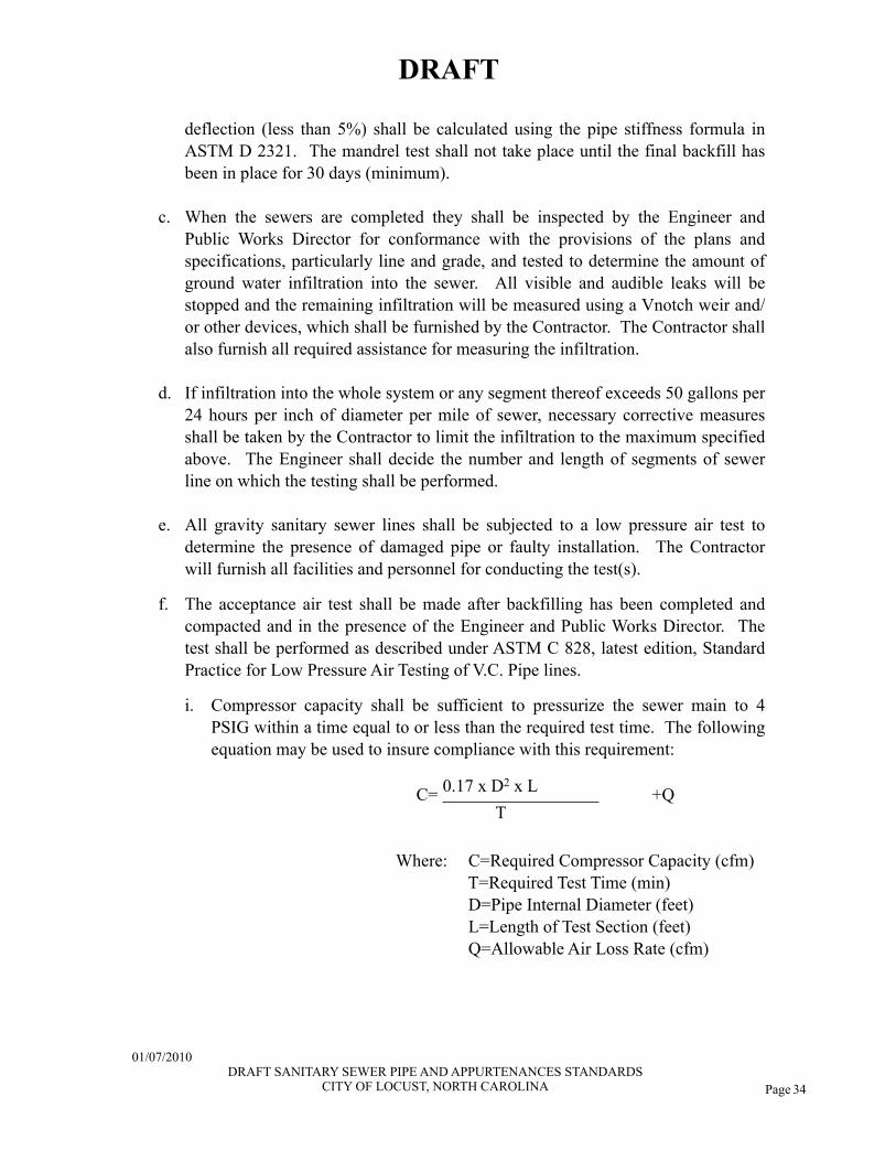
i. Compressor capacity shall be sufficient to pressurize the sewer main to 4 PSIG within a time equal to or less than the required test time. The following equation may be used to insure compliance with this requirement:
C= 0.17 x D2 x L +QC=T
+Q
Where: C=Required Compressor Capacity (cfm) T=Required Test Time (min) D=Pipe Internal Diameter (feet) L=Length of Test Section (feet) Q=Allowable Air Loss Rate (cfm)
DRAFT
01/07/2010 DRAFT SANITARY SEWER PIPE AND APPURTENANCES STANDARDS
CITY OF LOCUST, NORTH CAROLINA
Page 35
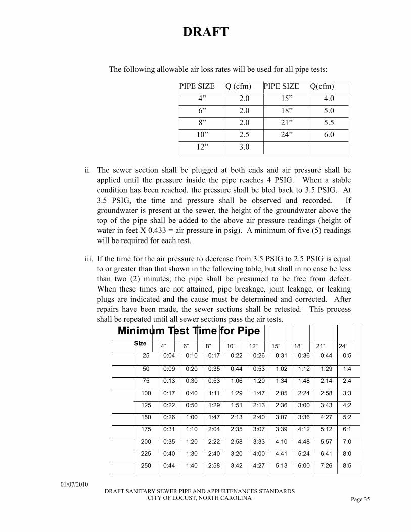
The following allowable air loss rates will be used for all pipe tests:
PIPE SIZE Q (cfm) PIPE SIZE Q(cfm)4” 2.0 15” 4.06” 2.0 18” 5.08” 2.0 21” 5.510” 2.5 24” 6.012” 3.0
ii. The sewer section shall be plugged at both ends and air pressure shall be applied until the pressure inside the pipe reaches 4 PSIG. When a stable condition has been reached, the pressure shall be bled back to 3.5 PSIG. At 3.5 PSIG, the time and pressure shall be observed and recorded. If groundwater is present at the sewer, the height of the groundwater above the top of the pipe shall be added to the above air pressure readings (height of water in feet X 0.433 = air pressure in psig). A minimum of five (5) readings will be required for each test.
iii. If the time for the air pressure to decrease from 3.5 PSIG to 2.5 PSIG is equal to or greater than that shown in the following table, but shall in no case be less than two (2) minutes; the pipe shall be presumed to be free from defect. When these times are not attained, pipe breakage, joint leakage, or leaking plugs are indicated and the cause must be determined and corrected. After repairs have been made, the sewer sections shall be retested. This process shall be repeated until all sewer sections pass the air tests.
Minimum Test Time for PipeMinimum Test Time for PipeMinimum Test Time for PipeMinimum Test Time for PipeMinimum Test Time for PipeMinimum Test Time for PipeMinimum Test Time for PipeMinimum Test Time for PipeMinimum Test Time for PipeMinimum Test Time for PipeMinimum Test Time for PipeMinimum Test Time for PipeMinimum Test Time for PipeMinimum Test Time for PipeMinimum Test Time for PipeMinimum Test Time for PipeMinimum Test Time for PipeMinimum Test Time for PipeMinimum Test Time for PipeMinimum Test Time for PipeMinimum Test Time for PipeMinimum Test Time for PipeSizeSize 4”4” 6”6” 8”8” 10”10” 12”12” 15”15” 18”18” 21”21” 24”24”24”
2525 0:040:04 0:100:10 0:170:17 0:220:22 0:260:26 0:310:31 0:360:36 0:440:44 0:530:530:53
5050 0:090:09 0:200:20 0:350:35 0:440:44 0:530:53 1:021:02 1:121:12 1:291:29 1:471:471:47
7575 0:130:13 0:300:30 0:530:53 1:061:06 1:201:20 1:341:34 1:481:48 2:142:14 2:402:402:40
100100 0:170:17 0:400:40 1:111:11 1:291:29 1:471:47 2:052:05 2:242:24 2:582:58 3:333:333:33
125125 0:220:22 0:500:50 1:291:29 1:511:51 2:132:13 2:362:36 3:003:00 3:433:43 4:274:274:27
150150 0:260:26 1:001:00 1:471:47 2:132:13 2:402:40 3:073:07 3:363:36 4:274:27 5:205:205:20
175175 0:310:31 1:101:10 2:042:04 2:352:35 3:073:07 3:393:39 4:124:12 5:125:12 6:146:146:14
200200 0:350:35 1:201:20 2:222:22 2:582:58 3:333:33 4:104:10 4:484:48 5:575:57 7:077:077:07
225225 0:400:40 1:301:30 2:402:40 3:203:20 4:004:00 4:414:41 5:245:24 6:416:41 8:008:008:00
250250 0:440:44 1:401:40 2:582:58 3:423:42 4:274:27 5:135:13 6:006:00 7:267:26 8:548:548:54
DRAFT
01/07/2010 DRAFT SANITARY SEWER PIPE AND APPURTENANCES STANDARDS
CITY OF LOCUST, NORTH CAROLINA
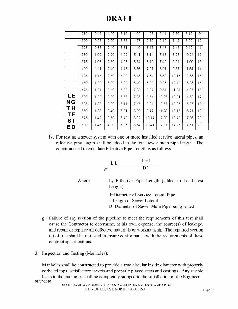
Page 36
L EN GT H T ES TE D
L EN GT H T ES TE D
L EN GT H T ES TE D
L EN GT H T ES TE D
275275 0:490:49 1:501:50 3:163:16 4:054:05 4:534:53 5:445:44 6:366:36 8:108:10 9:479:479:47
L EN GT H T ES TE D
L EN GT H T ES TE D
L EN GT H T ES TE D
L EN GT H T ES TE D
300300 0:530:53 2:002:00 3:333:33 4:274:27 5:205:20 6:156:15 7:127:12 8:558:55 10:4110:4110:41
L EN GT H T ES TE D
L EN GT H T ES TE D
L EN GT H T ES TE D
L EN GT H T ES TE D
325325 0:580:58 2:102:10 3:513:51 4:494:49 5:475:47 6:476:47 7:487:48 9:409:40 11:3411:3411:34
L EN GT H T ES TE D
L EN GT H T ES TE D
L EN GT H T ES TE D
L EN GT H T ES TE D
350350 1:021:02 2:202:20 4:094:09 5:115:11 6:146:14 7:187:18 8:258:25 10:2410:24 12:2812:2812:28
L EN GT H T ES TE D
L EN GT H T ES TE D
L EN GT H T ES TE D
L EN GT H T ES TE D
375375 1:061:06 2:302:30 4:274:27 5:345:34 6:406:40 7:497:49 9:019:01 11:0911:09 13:2113:2113:21
L EN GT H T ES TE D
L EN GT H T ES TE D
L EN GT H T ES TE D
L EN GT H T ES TE D
400400 1:111:11 2:402:40 4:454:45 5:565:56 7:077:07 8:218:21 9:379:37 11:5411:54 14:1414:1414:14
L EN GT H T ES TE D
L EN GT H T ES TE D
L EN GT H T ES TE D
L EN GT H T ES TE D
425425 1:151:15 2:502:50 5:025:02 6:186:18 7:347:34 8:528:52 10:1310:13 12:3812:38 15:0815:0815:08
L EN GT H T ES TE D
L EN GT H T ES TE D
L EN GT H T ES TE D
L EN GT H T ES TE D
450450 1:201:20 3:003:00 5:205:20 6:406:40 8:008:00 9:239:23 10:4910:49 13:2313:23 16:0116:0116:01
L EN GT H T ES TE D
L EN GT H T ES TE D
L EN GT H T ES TE D
L EN GT H T ES TE D
475475 1:241:24 3:103:10 5:385:38 7:037:03 8:278:27 9:549:54 11:2511:25 14:0714:07 16:5516:5516:55
L EN GT H T ES TE D
L EN GT H T ES TE D
L EN GT H T ES TE D
L EN GT H T ES TE D
500500 1:291:29 3:203:20 5:565:56 7:257:25 8:548:54 10:2610:26 12:0112:01 14:5214:52 17:4817:4817:48L EN GT H T ES TE D
L EN GT H T ES TE D
L EN GT H T ES TE D
L EN GT H T ES TE D
525525 1:331:33 3:303:30 6:146:14 7:477:47 9:219:21 10:5710:57 12:3712:37 15:3715:37 18:4218:4218:42
L EN GT H T ES TE D
L EN GT H T ES TE D
L EN GT H T ES TE D
L EN GT H T ES TE D
550550 1:381:38 3:403:40 6:316:31 8:098:09 9:479:47 11:2811:28 13:1313:13 16:2116:21 19:3519:3519:35
L EN GT H T ES TE D
L EN GT H T ES TE D
L EN GT H T ES TE D
L EN GT H T ES TE D
575575 1:421:42 3:503:50 6:496:49 8:328:32 10:1410:14 12:0012:00 13:4913:49 17:0617:06 20:2820:2820:28
L EN GT H T ES TE D
L EN GT H T ES TE D
L EN GT H T ES TE D
L EN GT H T ES TE D 600600 1:471:47 4:004:00 7:077:07 8:548:54 10:4110:41 12:3112:31 14:2514:25 17:5117:51 21:2221:2221:22
iv. For testing a sewer system with one or more installed service lateral pipes, an effective pipe length shall be added to the total sewer main pipe length. The equation used to calculate Effective Pipe Length is as follows:
L Le=
d2 x lL Le= D2
Where: Le=Effective Pipe Length (added to Total Test Length)
d=Diameter of Service Lateral Pipe l=Length of Sewer Lateral
D=Diameter of Sewer Main Pipe being tested
g. Failure of any section of the pipeline to meet the requirements of this test shall cause the Contractor to determine, at his own expense, the source(s) of leakage, and repair or replace all defective materials or workmanship. The repaired section(s) of line shall be re-tested to insure conformance with the requirements of these contract specifications.
3. Inspection and Testing (Manholes):
Manholes shall be constructed to provide a true circular inside diameter with properly corbeled tops, satisfactory inverts and properly placed steps and castings. Any visible leaks in the manholes shall be completely stopped to the satisfaction of the Engineer.
DRAFT
01/07/2010 DRAFT SANITARY SEWER PIPE AND APPURTENANCES STANDARDS
CITY OF LOCUST, NORTH CAROLINA
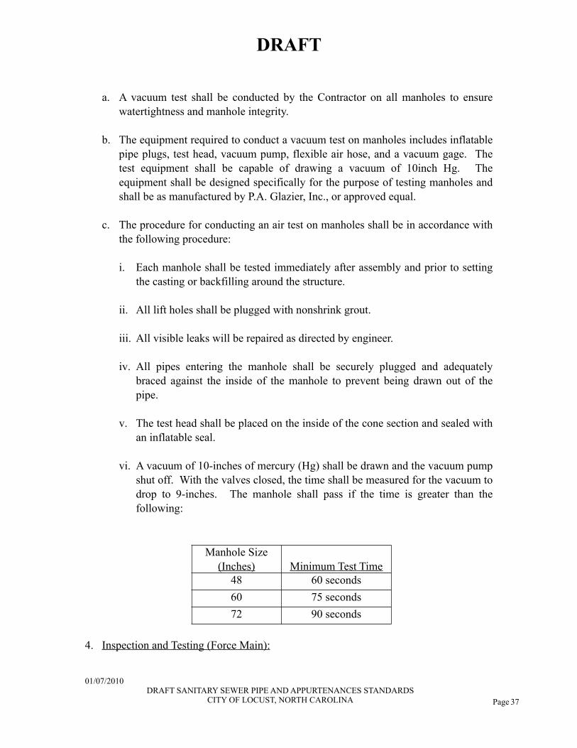
Page 37
a. A vacuum test shall be conducted by the Contractor on all manholes to ensure watertightness and manhole integrity.
b. The equipment required to conduct a vacuum test on manholes includes inflatable pipe plugs, test head, vacuum pump, flexible air hose, and a vacuum gage. The test equipment shall be capable of drawing a vacuum of 10inch Hg. The equipment shall be designed specifically for the purpose of testing manholes and shall be as manufactured by P.A. Glazier, Inc., or approved equal.
c. The procedure for conducting an air test on manholes shall be in accordance with the following procedure:
i. Each manhole shall be tested immediately after assembly and prior to setting the casting or backfilling around the structure.
ii. All lift holes shall be plugged with nonshrink grout.
iii. All visible leaks will be repaired as directed by engineer.
iv. All pipes entering the manhole shall be securely plugged and adequately braced against the inside of the manhole to prevent being drawn out of the pipe.
v. The test head shall be placed on the inside of the cone section and sealed with an inflatable seal.
vi. A vacuum of 10-inches of mercury (Hg) shall be drawn and the vacuum pump shut off. With the valves closed, the time shall be measured for the vacuum to drop to 9-inches. The manhole shall pass if the time is greater than the following:
Manhole Size (Inches) Minimum Test Time
48 60 seconds60 75 seconds72 90 seconds
4. Inspection and Testing (Force Main):
DRAFT
01/07/2010 DRAFT SANITARY SEWER PIPE AND APPURTENANCES STANDARDS
CITY OF LOCUST, NORTH CAROLINA
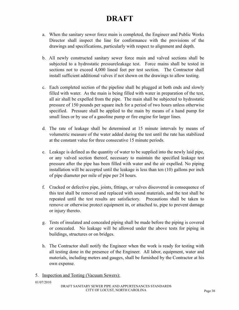
Page 38
a. When the sanitary sewer force main is completed, the Engineer and Public Works Director shall inspect the line for conformance with the provisions of the drawings and specifications, particularly with respect to alignment and depth.
b. All newly constructed sanitary sewer force main and valved sections shall be subjected to a hydrostatic pressureleakage test. Force mains shall be tested in sections not to exceed 4,000 lineal feet per test section. The Contractor shall install sufficient additional valves if not shown on the drawings to allow testing.
c. Each completed section of the pipeline shall be plugged at both ends and slowly filled with water. As the main is being filled with water in preparation of the test, all air shall be expelled from the pipe. The main shall be subjected to hydrostatic pressure of 150 pounds per square inch for a period of two hours unless otherwise specified. Pressure shall be applied to the main by means of a hand pump for small lines or by use of a gasoline pump or fire engine for larger lines.
d. The rate of leakage shall be determined at 15 minute intervals by means of volumetric measure of the water added during the test until the rate has stabilized at the constant value for three consecutive 15 minute periods.
e. Leakage is defined as the quantity of water to be supplied into the newly laid pipe, or any valved section thereof, necessary to maintain the specified leakage test pressure after the pipe has been filled with water and the air expelled. No piping installation will be accepted until the leakage is less than ten (10) gallons per inch of pipe diameter per mile of pipe per 24 hours.
f. Cracked or defective pipe, joints, fittings, or valves discovered in consequence of this test shall be removed and replaced with sound materials, and the test shall be repeated until the test results are satisfactory. Precautions shall be taken to remove or otherwise protect equipment in, or attached to, pipe to prevent damage or injury thereto.
g. Tests of insulated and concealed piping shall be made before the piping is covered or concealed. No leakage will be allowed under the above tests for piping in buildings, structures or on bridges.
h. The Contractor shall notify the Engineer when the work is ready for testing with all testing done in the presence of the Engineer. All labor, equipment, water and materials, including meters and gauges, shall be furnished by the Contractor at his own expense.
5. Inspection and Testing (Vacuum Sewers):
DRAFT
01/07/2010 DRAFT SANITARY SEWER PIPE AND APPURTENANCES STANDARDS
CITY OF LOCUST, NORTH CAROLINA
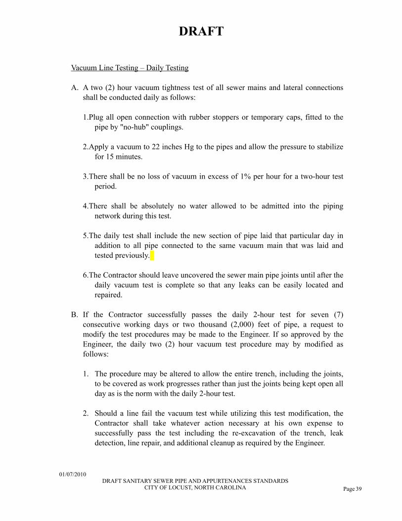
Page 39
Vacuum Line Testing – Daily Testing
A. A two (2) hour vacuum tightness test of all sewer mains and lateral connections shall be conducted daily as follows:
1.Plug all open connection with rubber stoppers or temporary caps, fitted to the pipe by "no-hub" couplings.
2.Apply a vacuum to 22 inches Hg to the pipes and allow the pressure to stabilize for 15 minutes.
3.There shall be no loss of vacuum in excess of 1% per hour for a two-hour test period.
4.There shall be absolutely no water allowed to be admitted into the piping network during this test.
5.The daily test shall include the new section of pipe laid that particular day in addition to all pipe connected to the same vacuum main that was laid and tested previously.
6.The Contractor should leave uncovered the sewer main pipe joints until after the daily vacuum test is complete so that any leaks can be easily located and repaired.
B. If the Contractor successfully passes the daily 2-hour test for seven (7) consecutive working days or two thousand (2,000) feet of pipe, a request to modify the test procedures may be made to the Engineer. If so approved by the Engineer, the daily two (2) hour vacuum test procedure may by modified as follows:
1. The procedure may be altered to allow the entire trench, including the joints,
to be covered as work progresses rather than just the joints being kept open all day as is the norm with the daily 2-hour test.
2. Should a line fail the vacuum test while utilizing this test modification, the Contractor shall take whatever action necessary at his own expense to successfully pass the test including the re-excavation of the trench, leak detection, line repair, and additional cleanup as required by the Engineer.
DRAFT
01/07/2010 DRAFT SANITARY SEWER PIPE AND APPURTENANCES STANDARDS
CITY OF LOCUST, NORTH CAROLINA

Page 40
3. After a failure, the Contractor must return to the standard testing procedures in order to "re-qualify" for the modified testing again.
4. This test modification is optional, and as such, the Contractor assumes all liability in its use, even if approved by the Engineer.
Vacuum Line Testing – Final Acceptance Test
A. A four (4) hour vacuum tightness test of the complete vacuum piping network, including all sewer mains and lateral connections shall be conducted as follows:
1. Subject the entire sewerage system to a vacuum of 22 inches Hg, and allow to stabilize for 15 minutes.
2. There shall be no loss greater than 1% per hour over a four (4) hour test period.
3. There shall be absolutely no water allowed to enter the piping system or the vacuum station during this test.
B. Contractor to provide 48 hours notice to Engineer prior to test.
C. Contractor to assure all division valves are open prior to beginning of Final Acceptance Test.
D. Final Acceptance Test shall be recorded on approved vacuum chart recorder. This chart will not be considered valid unless witnessed by Engineer on test equipment at beginning and the end of vacuum test period.
E. Engineer will sign and date chart to verify witness of test. This signature does not indicate acceptance of the system.
Vacuum Line Flushing
A. After successful final four (4) hour acceptance testing, flush lines to remove debris and foreign materials that accumulated during construction.
B. Suggested procedure (In the absence of special test apparatus, this procedure will require the use of vacuum valves, which must be installed by the OWNER. Coordination is therefore required.):
1. Place system under vacuum.
DRAFT
01/07/2010 DRAFT SANITARY SEWER PIPE AND APPURTENANCES STANDARDS
CITY OF LOCUST, NORTH CAROLINA
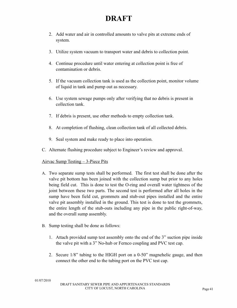
Page 41
2. Add water and air in controlled amounts to valve pits at extreme ends of system.
3. Utilize system vacuum to transport water and debris to collection point.
4. Continue procedure until water entering at collection point is free of contamination or debris.
5. If the vacuum collection tank is used as the collection point, monitor volume of liquid in tank and pump out as necessary.
6. Use system sewage pumps only after verifying that no debris is present in collection tank.
7. If debris is present, use other methods to empty collection tank.
8. At completion of flushing, clean collection tank of all collected debris.
9. Seal system and make ready to place into operation.
C. Alternate flushing procedure subject to Engineer’s review and approval.
Airvac Sump Testing – 3-Piece Pits
A. Two separate sump tests shall be performed. The first test shall be done after the valve pit bottom has been joined with the collection sump but prior to any holes being field cut. This is done to test the O-ring and overall water tightness of the joint between these two parts. The second test is performed after all holes in the sump have been field cut, grommets and stub-out pipes installed and the entire valve pit assembly installed in the ground. This test is done to test the grommets, the entire length of the stub-outs including any pipe in the public right-of-way, and the overall sump assembly.
B. Sump testing shall be done as follows:
1. Attach provided sump test assembly onto the end of the 3” suction pipe inside the valve pit with a 3” No-hub or Fernco coupling and PVC test cap.
2. Secure 1/8” tubing to the HIGH port on a 0-50” magnehelic gauge, and then connect the other end to the tubing port on the PVC test cap.
DRAFT
01/07/2010 DRAFT SANITARY SEWER PIPE AND APPURTENANCES STANDARDS
CITY OF LOCUST, NORTH CAROLINA
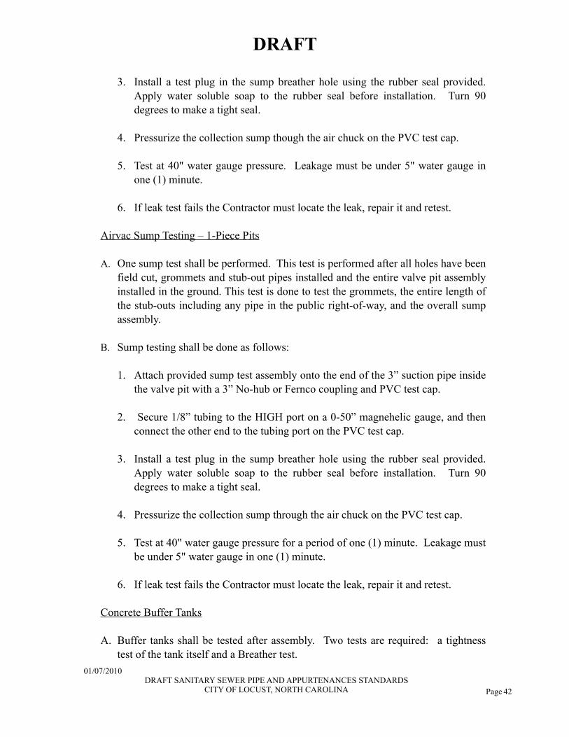
Page 42
3. Install a test plug in the sump breather hole using the rubber seal provided. Apply water soluble soap to the rubber seal before installation. Turn 90 degrees to make a tight seal.
4. Pressurize the collection sump though the air chuck on the PVC test cap.
5. Test at 40" water gauge pressure. Leakage must be under 5" water gauge in one (1) minute.
6. If leak test fails the Contractor must locate the leak, repair it and retest.
Airvac Sump Testing – 1-Piece Pits
A. One sump test shall be performed. This test is performed after all holes have been field cut, grommets and stub-out pipes installed and the entire valve pit assembly installed in the ground. This test is done to test the grommets, the entire length of the stub-outs including any pipe in the public right-of-way, and the overall sump assembly.
B. Sump testing shall be done as follows:
1. Attach provided sump test assembly onto the end of the 3” suction pipe inside the valve pit with a 3” No-hub or Fernco coupling and PVC test cap.
2. Secure 1/8” tubing to the HIGH port on a 0-50” magnehelic gauge, and then connect the other end to the tubing port on the PVC test cap.
3. Install a test plug in the sump breather hole using the rubber seal provided. Apply water soluble soap to the rubber seal before installation. Turn 90 degrees to make a tight seal.
4. Pressurize the collection sump through the air chuck on the PVC test cap.
5. Test at 40" water gauge pressure for a period of one (1) minute. Leakage must be under 5" water gauge in one (1) minute.
6. If leak test fails the Contractor must locate the leak, repair it and retest.
Concrete Buffer Tanks
A. Buffer tanks shall be tested after assembly. Two tests are required: a tightness test of the tank itself and a Breather test.
DRAFT
01/07/2010 DRAFT SANITARY SEWER PIPE AND APPURTENANCES STANDARDS
CITY OF LOCUST, NORTH CAROLINA
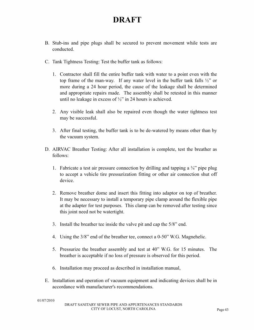
Page 43
B. Stub-ins and pipe plugs shall be secured to prevent movement while tests are conducted.
C. Tank Tightness Testing: Test the buffer tank as follows:
1. Contractor shall fill the entire buffer tank with water to a point even with the top frame of the man-way. If any water level in the buffer tank falls ½” or more during a 24 hour period, the cause of the leakage shall be determined and appropriate repairs made. The assembly shall be retested in this manner until no leakage in excess of ½” in 24 hours is achieved.
2. Any visible leak shall also be repaired even though the water tightness test may be successful.
3. After final testing, the buffer tank is to be de-watered by means other than by the vacuum system.
D. AIRVAC Breather Testing: After all installation is complete, test the breather as follows:
1. Fabricate a test air pressure connection by drilling and tapping a ¾” pipe plug to accept a vehicle tire pressurization fitting or other air connection shut off device.
2. Remove breather dome and insert this fitting into adaptor on top of breather. It may be necessary to install a temporary pipe clamp around the flexible pipe at the adapter for test purposes. This clamp can be removed after testing since this joint need not be watertight.
3. Install the breather tee inside the valve pit and cap the 5/8” end.
4. Using the 3/8” end of the breather tee, connect a 0-50” W.G. Magnehelic.
5. Pressurize the breather assembly and test at 40” W.G. for 15 minutes. The breather is acceptable if no loss of pressure is observed for this period.
6. Installation may proceed as described in installation manual,
E. Installation and operation of vacuum equipment and indicating devices shall be in accordance with manufacturer's recommendations.
DRAFT
01/07/2010 DRAFT SANITARY SEWER PIPE AND APPURTENANCES STANDARDS
CITY OF LOCUST, NORTH CAROLINA
Page 44
Final Acceptance:
1. All discharge points to the existing system, force main, or gravity, shall remain plugged, and out of service until final acceptance by the City of Locust.
2. The Engineer will notify the Contractor, in writing, as to the satisfactory completion of the work in any or all sections of gravity sanitary sewer pipe, force main and manholes, included in the project.
3. Upon such notification, the Contractor shall immediately remove all construction equipment, excess materials, tools, debris, etc. from the site(s) and leave the same in a neat, orderly condition acceptable to the Engineer.
5. Final landscaping requirements and restoration of surfaces shall then be completed by the Contractor in accordance with their respective specifications and as shown on the drawings.
DRAFT
01/07/2010 DRAFT SANITARY SEWER PIPE AND APPURTENANCES STANDARDS
CITY OF LOCUST, NORTH CAROLINA