split plummer block housings - skf.com12-107554-16/13186 en - 07 sonl_tcm_12... · split plummer...
TRANSCRIPT
Split plummer block housingsSONL series
Bearing typesSelf-aligning ball bearings•Spherical roller bearings•CARB toroidal roller bearings•
Bearing dimension series22•
Shaft diameter range75 to 240 mm•2 • 15/16 to 8 15/16 in.
Typical shaft-bearing combinationsPlain shaft with bearing on an adapter •sleeveStepped shaft with bearing on a cylin-•drical seat
SealsLabyrinth•
LubricationOil bath lubrication with • a pick-up ringCirculating oil lubrication systems•
MaterialsGrey cast iron•Spheroidal graphite cast iron•
MountingFour-bolt• mounting
Compliance to standardsNot standardized•
SupersedesSOFN in the 2(00) and 5(00) series•
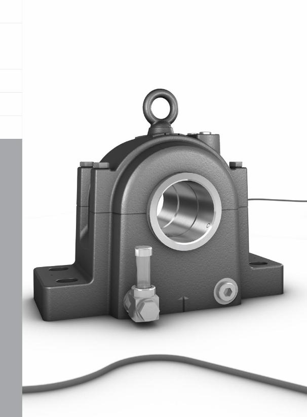
SONL plummer (pillow) block housings are specially designed for oil lubrication. They can accommodate high temperatures and bearings operating at high speeds. They have a strong, stiff design and are characterized by a number of built-in features that maximize the effects of the lubricant and extend bearing service life.
SONL housings can be found in applications ranging from fans and flywheels to paper machines and emergency power generators.
349
7
Split plummer block housingsSONL series
Designations . . . . . . . . . . . . . . . . . . . . . 351
Standard housing design . . . . . . . . . . . 353Features and benefits . . . . . . . . . . . . . . 354Housing material . . . . . . . . . . . . . . . . . . 355
Paint, corrosion protection . . . . . . . . 355Dimension standards . . . . . . . . . . . . . . . 355
Interchangeabilty . . . . . . . . . . . . . . . . 355
Housing variants. . . . . . . . . . . . . . . . . . 356Housing material . . . . . . . . . . . . . . . . . . 356Bearing seat tolerance . . . . . . . . . . . . . . 356Housings for circulating oil lubrication systems . . . . . . . . . . . . . . . . 356
Sealing solutions . . . . . . . . . . . . . . . . . 356Seal kits . . . . . . . . . . . . . . . . . . . . . . . . . . 358End covers . . . . . . . . . . . . . . . . . . . . . . . 359High-temperature seals . . . . . . . . . . . . . 359
Design considerations . . . . . . . . . . . . . 360Typical shaft-bearing combinations . . . 360Locating and non-locating bearing positions . . . . . . . . . . . . . . . . . . 360Load carrying ability . . . . . . . . . . . . . . . . 361Operating temperature . . . . . . . . . . . . . 362Operating speed . . . . . . . . . . . . . . . . . . . 362Shaft specifications . . . . . . . . . . . . . . . . 362Attachment bolt recommendations . . . . 363
Lubrication . . . . . . . . . . . . . . . . . . . . . . 364Oil bath lubrication with a pick-up ring . 364Circulating oil lubrication systems . . . . . 366
Mounting . . . . . . . . . . . . . . . . . . . . . . . . 368Cap bolt torque specifications . . . . . . . . 368Pinning or supporting the housing . . . . 368
Condition monitoring . . . . . . . . . . . . . . 368
Accessories . . . . . . . . . . . . . . . . . . . . . . 369
Ordering information . . . . . . . . . . . . . . 369
Product tablesSONL plummer block housings 7.1 for bearings on an adapter sleeve, metric shafts . . . . . . . . . . . . . . . . . 370SONL plummer block housings 7.2 for bearings on an adapter sleeve, inch shafts . . . . . . . . . . . . . . . . . . . 374SONL plummer block housings 7.3 for bearings on a cylindrical seat on stepped shafts . . . . . . . . . . . . . 378
350
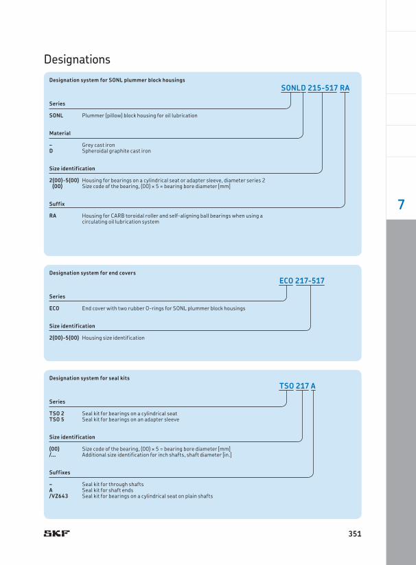
DesignationsDesignation system for SONL plummer block housings
Series
SONL Plummer (pillow) block housing for oil lubrication
Material
– Grey cast ironD Spheroidal graphite cast iron
Size identification
2(00)-5(00) Housing for bearings on a cylindrical seat or adapter sleeve, diameter series 2 (00) Size code of the bearing, (00) ¥ 5 = bearing bore diameter [mm]
Suffix
RA Housing for CARB toroidal roller and self-aligning ball bearings when using a circulating oil lubrication system
SONLD 215-517 RA
Designation system for end covers
Series
ECO End cover with two rubber O-rings for SONL plummer block housings
Size identification
2(00)-5(00) Housing size identification
ECO 217-517
Designation system for seal kits
Series
TSO 2 Seal kit for bearings on a cylindrical seatTSO 5 Seal kit for bearings on an adapter sleeve
Size identification
(00) Size code of the bearing, (00) ¥ 5 = bearing bore diameter [mm]/… Additional size identification for inch shafts, shaft diameter [in.]
Suffixes
– Seal kit for through shafts A Seal kit for shaft ends/VZ643 Seal kit for bearings on a cylindrical seat on plain shafts
TSO 217 A
351
7
Split plummer block housings SONL series
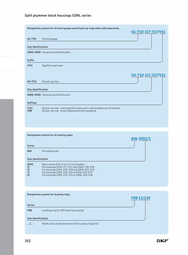
Designation system for oil level gauges and oil pick up rings when sold separately
GG-TSO Oil level gauge
Size identification
2(00)-5(00) Housing size identification
Suffix
/V51 Signifies spare part
GH-TSO Oil pick-up ring
Size identification
2(00)-5(00) Housing size identification
Suffixes
/V51 Oil pick-up ring – steel (signifies spare parts with standard performance)/MB Oil pick-up ring – brass (replacement for standard)
GG-TSO 217-517/V51
GH-TSO 217-517/V51
Designation system for oil cooling tubes
Series
AVA Oil cooling tube
Size identification
0001 Basic size to fit G 3/4 to G 1 1/2 oil outlets/1 For housings SONL 217-517 and SONL 218-518/2 For housings SONL 220-520 and SONL 222-522/3 For housings SONL 224-524 to SONL 232-532/4 For housings SONL 234-534 to SONL 248-548
AVA-0001/1
Designation system for locating rings
Series
FRB Locating ring for SKF bearing housings
Size identification
.../... Width and outside diameter of the locating ring [mm]
FRB 11/230
352
Standard housing design
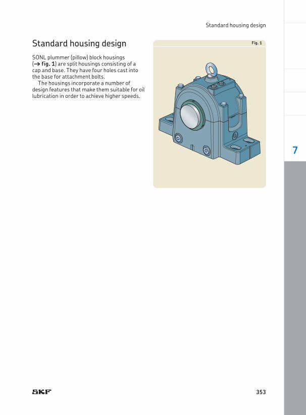
Standard housing designSONL plummer (pillow) block housings († fig. 1) are split housings consisting of a cap and base. They have four holes cast into the base for attachment bolts.
The housings incorporate a number of design features that make them suitable for oil lubrication in order to achieve higher speeds.
Fig. 1
353
7
Split plummer block housings SONL series
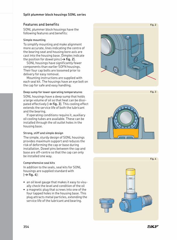
Fig. 2
Fig. 3
Fig. 4
Features and benefitsSONL plummer block housings have the following features and benefits:
Simple mounting To simplify mounting and make alignment more accurate, lines indicating the centre of the bearing seat and housing bore axis are cast into the housing base. Dimples indicate the position for dowel pins († fig. 2).
SONL housings have significantly fewer components than earlier SOFN housings. Their four cap bolts are loosened prior to delivery for easy removal.
Mounting instructions are supplied with each seal kit. The housings have an eye bolt on the cap for safe and easy handling.
Deep sump for lower operating temperaturesSONL housings have a deep sump that holds a large volume of oil so that heat can be dissi-pated effectively († fig. 3). This cooling effect extends the service life of both the lubricant and the bearing.
If operating conditions require it, auxiliary oil cooling tubes are available. These can be installed through the oil outlet holes in the housing base.
Strong, stiff and simple designThe simple, sturdy design of SONL housings provides maximum support and reduces the risk of deforming the cap or base during installation. Dowel pins between the cap and base are off-centre so that the cap can only be installed one way.
Comprehensive seal kitsIn addition to the seals, seal kits for SONL housings are supplied standard with († fig. 4):
an• oil level gauge that makes it easy to visu-ally check the level and condition of the oila• magnetic plug that screws into one of the four tapped holes in the housing base. This plug attracts metal particles, extending the service life of the lubricant and bearing.
354
Standard housing design
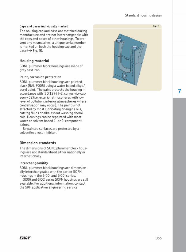
Caps and bases individually markedThe housing cap and base are matched during manufacture and are not interchangeable with the caps and bases of other housings. To pre-vent any mismatches, a unique serial number is marked on both the housing cap and the base († fig. 5).
Housing materialSONL plummer block housings are made of grey cast iron.
Paint, corrosion protectionSONL plummer block housings are painted black (RAL 9005) using a water based alkyd/acryl paint. The paint protects the housing in accordance with ISO 12944-2, corrosivity cat-egory C2 (i.e. exterior atmospheres with low level of pollution, interior atmospheres where condensation may occur). The paint is not affected by most lubricating or engine oils, cutting fluids or alkalescent washing chemi-cals. Housings can be repainted with most water or solvent based 1- or 2-component paints.
Unpainted surfaces are protected by a solventless rust inhibitor.
Dimension standardsThe dimensions of SONL plummer block hous-ings are not standardized either nationally or internationally.
InterchangeabilitySONL plummer block housings are dimension-ally interchangeable with the earlier SOFN housings in the 2(00) and 5(00) series.
3(00) and 6(00) series SOFN housings are still available. For additional information, contact the SKF application engineering service.
Fig. 5
355
7
Split plummer block housings SONL series
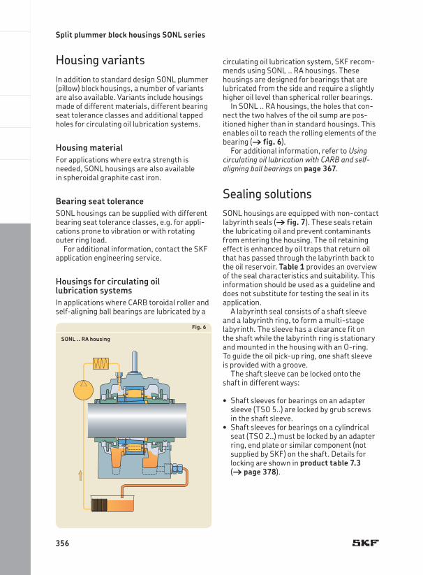
circulating oil lubrication system, SKF recom-mends using SONL .. RA housings. These housings are designed for bearings that are lubricated from the side and require a slightly higher oil level than spherical roller bearings.
In SONL .. RA housings, the holes that con-nect the two halves of the oil sump are pos-itioned higher than in standard housings. This enables oil to reach the rolling elements of the bearing († fig. 6).
For additional information, refer to Using circulating oil lubrication with CARB and self-aligning ball bearings on page 367.
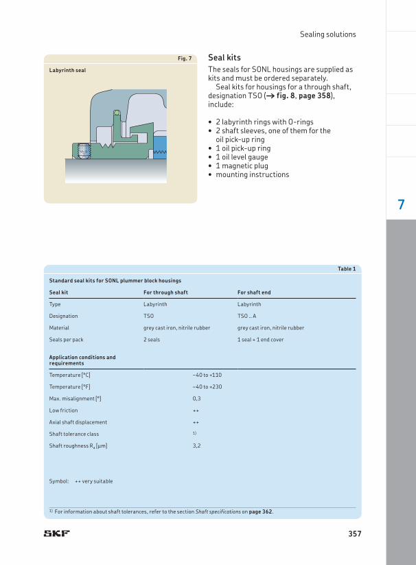
Sealing solutionsSONL housings are equipped with non-contact labyrinth seals († fig. 7). These seals retain the lubricating oil and prevent contaminants from entering the housing. The oil retaining effect is enhanced by oil traps that return oil that has passed through the labyrinth back to the oil reservoir. Table 1 provides an overview of the seal characteristics and suitability. This information should be used as a guideline and does not substitute for testing the seal in its application.
A labyrinth seal consists of a shaft sleeve and a labyrinth ring, to form a multi-stage labyrinth. The sleeve has a clearance fit on the shaft while the labyrinth ring is stationary and mounted in the housing with an O-ring. To guide the oil pick-up ring, one shaft sleeve is provided with a groove.
The shaft sleeve can be locked onto the shaft in different ways:
Shaft• sleeves for bearings on an adapter sleeve (TSO 5..) are locked by grub screws in the shaft sleeve. Shaft• sleeves for bearings on a cylindrical seat (TSO 2..) must be locked by an adapter ring, end plate or similar component (not supplied by SKF) on the shaft. Details for locking are shown in product table 7.3 († page 378).
Housing variantsIn addition to standard design SONL plummer (pillow) block housings, a number of variants are also available. Variants include housings made of different materials, different bearing seat tolerance classes and additional tapped holes for circulating oil lubrication systems.
Housing materialFor applications where extra strength is needed, SONL housings are also available in spheroidal graphite cast iron.
Bearing seat toleranceSONL housings can be supplied with different bearing seat tolerance classes, e.g. for appli-cations prone to vibration or with rotating outer ring load.
For additional information, contact the SKF application engineering service.
Housings for circulating oil lubrication systemsIn applications where CARB toroidal roller and self-aligning ball bearings are lubricated by a
Fig. 6
SONL .. RA housing
356
Sealing solutions
Fig. 7
Labyrinth seal
Table 1
Standard seal kits for SONL plummer block housings
Seal kit For through shaft For shaft end
Type Labyrinth Labyrinth
Designation TSO TSO .. A
Material grey cast iron, nitrile rubber grey cast iron, nitrile rubber
Seals per pack 2 seals 1 seal + 1 end cover
Application conditions and requirements
Temperature [°C] –40 to +110
Temperature [°F] –40 to +230
Max. misalignment [°] 0,3
Low friction ++
Axial shaft displacement ++
Shaft tolerance class 1)
Shaft roughness Ra [μm] 3,2
Symbol: ++ very suitable
1) For information about shaft tolerances, refer to the section Shaft specifications on page 362.
Seal kitsThe seals for SONL housings are supplied as kits and must be ordered separately.
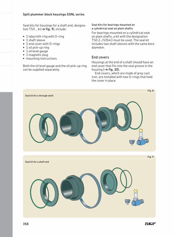
Seal kits for housings for a through shaft, designation TSO († fig. 8, page 358), include:
2 labyrinth rings with O-rings•2 • shaft sleeves, one of them for the oil pick-up ring1 oil pick-up ring•1 oil level gauge•1 magnetic plug•mounting instructions•
357
7
Split plummer block housings SONL series
Seal kits for housings for a shaft end, designa-tion TSO .. A († fig. 9), include:
1 labyrinth ring with O-ring•1 • shaft sleeve1 end cover with O-rings•1 oil pick-up ring•1 oil level gauge•1 magnetic plug•mounting instructions•
Both the oil level gauge and the oil pick-up ring can be supplied separately.
Fig. 8
Seal kit for a through shaft
Fig. 9
Seal kit for a shaft end
Seal kits for bearings mounted on a cylindrical seat on plain shaftsFor bearings mounted on a cylindrical seat on plain shafts, a kit with the designation TSO 2../VZ643 must be used. The seal kit includes two shaft sleeves with the same bore diameter.
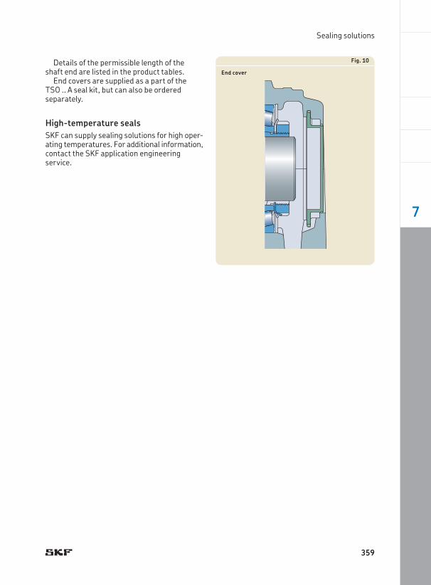
End coversHousings at the end of a shaft should have an end cover that fits into the seal groove in the housing († fig. 10).
End covers, which are made of grey cast iron, are installed with two O-rings that hold the cover in place.
358
Sealing solutions
Details of the permissible length of the shaft end are listed in the product tables.
End covers are supplied as a part of the TSO .. A seal kit, but can also be ordered separately.
High-temperature sealsSKF can supply sealing solutions for high oper-ating temperatures. For additional information, contact the SKF application engineering service.
Fig. 10
End cover
359
7
Split plummer block housings SONL series
Plain shaft with bearing on an adapter sleeveHousings, appropriate parts and dimensions are listed in product tables 7.1 († page 370)and 7.2 († page 374).
Stepped shaft with bearing on a cylindrical seatHousings, appropriate parts and dimensions are listed in product table 7.3 († page 378).
The bearing is located axially by an inboard labyrinth seal shaft sleeve that abuts the shaft shoulder, and an outboard labyrinth seal shaft sleeve that is held in place by another compo-nent (not supplied by SKF). The outside diam-eter of this component must be at least as large as that of the sleeve.
Plain shaft with bearing on a cylindrical seatWhen using an SONL housing for this arrange-ment, a /VZ643 seal kit must be used. The bearing and labyrinth seal shaft sleeves must be located axially on both sides by other com-ponents (not supplied by SKF) on the shaft.
Locating and non-locating bearing positionsSONL housings can be used for both the locat-ing and non-locating bearing positions.
The housings are machined standard for bearings in the non-locating position. Bear-ings in the locating position as well as CARB toroidal roller bearings must be secured in the housing on both sides with locating rings. Appropriate locating rings are listed in the product tables.
Design considerationsFor general information about system design, refer to the following sections:
Typical • shaft-bearing combinations († page 41)Locating/non-locating bearing systems• († page 40)L• oad carrying ability († page 44)A• xial load carrying ability for bearings on sleeves († page 44)Specifications for • shafts and housing support surfaces († page 45)
For additional information about rolling bear-ings and adapter sleeves, refer to the product information available online at skf.com/bearings.
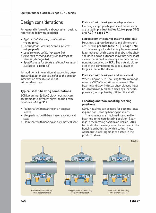
Typical shaft-bearing combinationsSONL plummer (pillow) block housings can accommodate different shaft-bearing com-binations († fig. 11):
Plain shaft with bearing on an adapter •sleeveStepped shaft with bearing on a cylindrical •seatPlain shaft with bearing on a cylindrical seat•
Fig. 11
Plain shaft with bearing on an adapter sleeve
Stepped shaft with bearing on a cylindrical seat
Plain shaft with bearing on a cylindrical seat
360
Design considerations
Load carrying abilitySONL housings are intended for loads acting perpendicularly toward the support surface. The housings should always be supported over the entire base. Perpendicular loads acting towards the base are limited only by the bear-ing. If loads acting in other directions occur, be sure that the magnitude of the load is permis-sible for the housing, the cap bolts and the attachment bolts. When housings are sub-jected to cyclic loads or dynamic imbalance,
contact the SKF application engineering service.
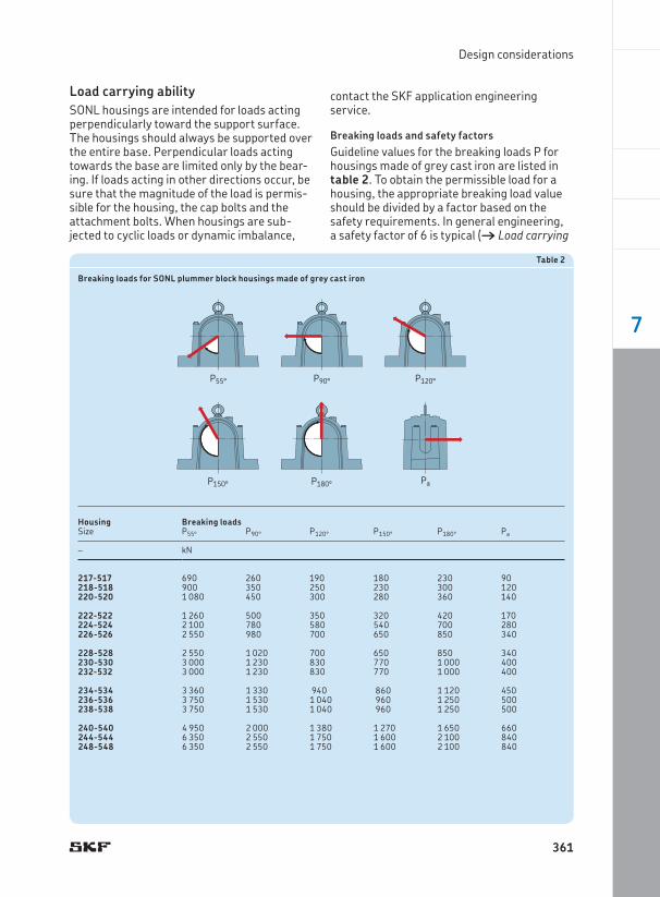
Breaking loads and safety factorsGuideline values for the breaking loads P for housings made of grey cast iron are listed in table 2. To obtain the permissible load for a housing, the appropriate breaking load value should be divided by a factor based on the safety requirements. In general engineering, a safety factor of 6 is typical († Load carrying
Table 2
Breaking loads for SONL plummer block housings made of grey cast iron
Housing Breaking loadsSize P55° P90° P120° P150° P180° Pa
– kN
217-517 690 260 190 180 230 90218-518 900 350 250 230 300 120220-520 1 080 450 300 280 360 140
222-522 1 260 500 350 320 420 170224-524 2 100 780 580 540 700 280226-526 2 550 980 700 650 850 340
228-528 2 550 1 020 700 650 850 340230-530 3 000 1 230 830 770 1 000 400232-532 3 000 1 230 830 770 1 000 400
234-534 3 360 1 330 940 860 1 120 450236-536 3 750 1 530 1 040 960 1 250 500238-538 3 750 1 530 1 040 960 1 250 500
240-540 4 950 2 000 1 380 1 270 1 650 660244-544 6 350 2 550 1 750 1 600 2 100 840248-548 6 350 2 550 1 750 1 600 2 100 840
P55° P90° P120°
P150° P180° Pa
361
7
Split plummer block housings SONL series
ability, page 44). The permissible load can only be exploited if the cap bolts are tightened at least to the torque values listed in table 3. The load Pa is the axial breaking load of the hous-ing. If the incorporated bearing is mounted on a sleeve, check the permissible axial load for the sleeve.
For housings made of spheroidal graphite cast iron, the values obtained from table 2 on page 361 should be multiplied by a factor of 1,8.
Additional housing supportWhen loads act at angles between 55° and 120°, or when the axial loads are greater than 5% of P180° († table 2 on page 361), the hous-ing should be pinned to the support surface or a stop should be provided to counter the load. The dowel pins or stop should be sufficiently strong to accommodate the loads acting par-allel to the support surface.
Recommendations for the position and size of the holes to accommodate dowel pins are provided in table 8 on page 368.
Load carrying ability of the cap boltsApproximate values for the yield points for four cap bolts are provided in table 3. The values in table 3 apply to 8.8 class cap bolts, which are supplied with SONL housings.
Operating temperatureThe permissible operating temperature is mainly limited by the seals († table 1, page 357), the oil level gauge and the lubricant. For temperature limits of SKF bearings and lubri-cants, refer to the product information avail-able online at skf.com/bearings. The permis-sible operating temperature for the oil level gauge is 110 °C (230 °F).
The housing material does not have any additional temperature limits, except for very low temperature applications where impact strength could be a factor.
The housing paint is heat resistant up to 80 °C (175 °F) material temperature or 100 °C (210 °F) ambient temperature.
When temperatures outside the permissible range are expected, contact the SKF application engineering service.
Operating speedThe permissible operating speed of the incor-porated bearing is not limited by the housing.
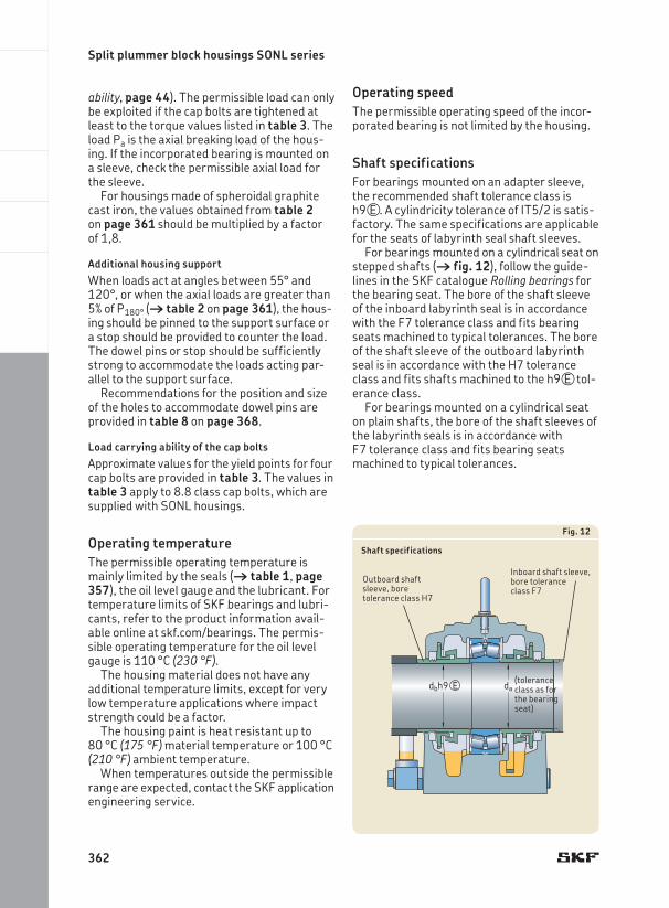
Shaft specificationsFor bearings mounted on an adapter sleeve, the recommended shaft tolerance class is h9VE . A cylindricity tolerance of IT5/2 is satis-factory. The same specifications are applicable for the seats of labyrinth seal shaft sleeves.
For bearings mounted on a cylindrical seat on stepped shafts († fig. 12), follow the guide-lines in the SKF catalogue Rolling bearings for the bearing seat. The bore of the shaft sleeve of the inboard labyrinth seal is in accordance with the F7 tolerance class and fits bearing seats machined to typical tolerances. The bore of the shaft sleeve of the outboard labyrinth seal is in accordance with the H7 tolerance class and fits shafts machined to the h9VE tol-erance class.
For bearings mounted on a cylindrical seat on plain shafts, the bore of the shaft sleeves of the labyrinth seals is in accordance with F7 tolerance class and fits bearing seats machined to typical tolerances.
dadbh9 E
Fig. 12
Shaft specifications
(tolerance class as for the bearing seat)
Outboard shaft sleeve, bore tolerance class H7
Inboard shaft sleeve, bore tolerance class F7
362
Design considerations
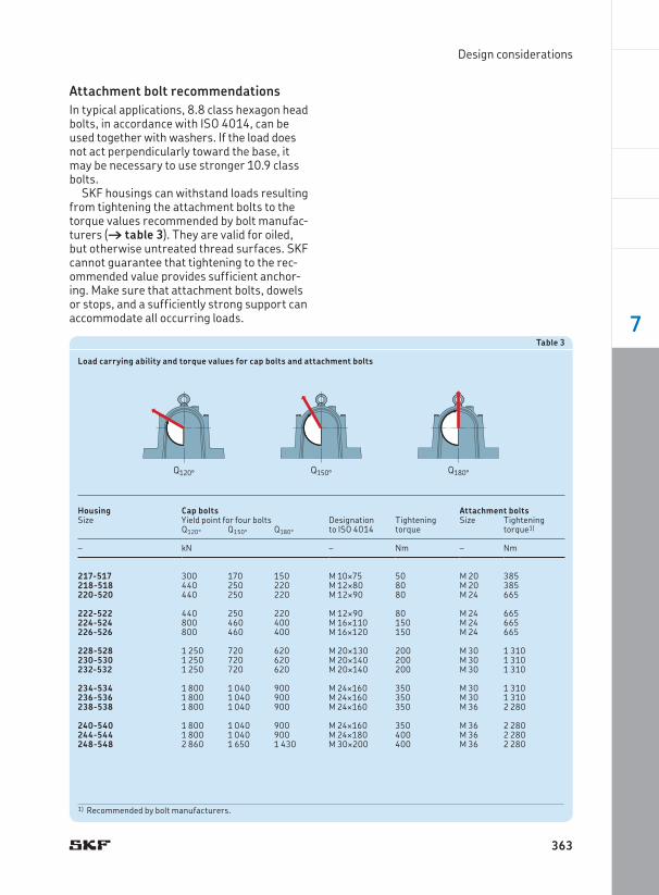
Attachment bolt recommendationsIn typical applications, 8.8 class hexagon head bolts, in accordance with ISO 4014, can be used together with washers. If the load does not act perpendicularly toward the base, it may be necessary to use stronger 10.9 class bolts.
SKF housings can withstand loads resulting from tightening the attachment bolts to the torque values recommended by bolt manufac-turers († table 3). They are valid for oiled, but otherwise untreated thread surfaces. SKF cannot guarantee that tightening to the rec-ommended value provides sufficient anchor-ing. Make sure that attachment bolts, dowels or stops, and a sufficiently strong support can accommodate all occurring loads.
Table 3
Load carrying ability and torque values for cap bolts and attachment bolts
Housing Cap bolts Attachment boltsSize Yield point for four bolts Designation
to ISO 4014Tightening torque
Size Tightening torque1)Q120° Q150° Q180°
– kN – Nm – Nm
217-517 300 170 150 M 10¥75 50 M 20 385218-518 440 250 220 M 12¥80 80 M 20 385220-520 440 250 220 M 12¥90 80 M 24 665
222-522 440 250 220 M 12¥90 80 M 24 665224-524 800 460 400 M 16¥110 150 M 24 665226-526 800 460 400 M 16¥120 150 M 24 665
228-528 1 250 720 620 M 20¥130 200 M 30 1 310230-530 1 250 720 620 M 20¥140 200 M 30 1 310232-532 1 250 720 620 M 20¥140 200 M 30 1 310
234-534 1 800 1 040 900 M 24¥160 350 M 30 1 310236-536 1 800 1 040 900 M 24¥160 350 M 30 1 310238-538 1 800 1 040 900 M 24¥160 350 M 36 2 280
240-540 1 800 1 040 900 M 24¥160 350 M 36 2 280244-544 1 800 1 040 900 M 24¥180 400 M 36 2 280248-548 2 860 1 650 1 430 M 30¥200 400 M 36 2 280
Q120° Q150° Q180°
1) Recommended by bolt manufacturers.
363
7
Split plummer block housings SONL series
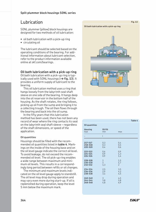
LubricationSONL plummer (pillow) block housings are designed for two methods of oil lubrication:
oil bath lubrication with a pick-up ring•circulating oil•
The lubricant should be selected based on the operating conditions of the bearing. For add-itional information about lubricant selection, refer to the product information available online at skf.com/bearings.
Oil bath lubrication with a pick-up ringOil bath lubrication with a pick-up ring is typ-ically used with SONL housings († fig. 13). It provides a uniform supply of lubricant to the bearing.
This oil lubrication method uses a ring that hangs loosely from the labyrinth seal shaft sleeve on one side of the bearing. It hangs deep into the oil reservoir in the bottom half of the housing. As the shaft rotates, the ring follows, picking up oil from the sump and bringing it to a collecting trough. The oil then flows through the bearing and back into the oil sump.
In the fifty years that this lubrication method has been used, there has not been any record of wear where the ring contacts its seat on the labyrinth seal shaft sleeve – regardless of the shaft dimensions, or speed of the application.
Oil quantitiesHousings should be filled with the recom-mended oil quantities listed in table 4. Mark-ings on the inside of the housing base and on the oil level gauge indicate the correct oil level. To avoid leakage, do not exceed the recom-mended oil level. The oil pick-up ring enables a wide range between maximum and mini-mum oil levels. This results in a correspond-ingly long period between refills or oil changes.
The minimum and maximum levels indi-cated on the oil level gauge apply to standstill. The oil level may drop during operation and may vary even more during start-up. If oil is replenished during operation, keep the level 5 mm below the maximum mark.
Fig. 13
Oil bath lubrication with a pick-up ring
Table 4
Oil quantities
Housing Oil fillSize min max
– l
217-517 0,3 0,4218-518 0,3 0,5220-520 0,4 0,6
222-522 0,6 0,9224-524 0,9 1,3226-526 0,9 1,4
228-528 1 1,5230-530 1 1,7232-532 1,3 2
234-534 2,5 3,5236-536 2,9 4,2238-538 3,1 4,5
240-540 3 4,5244-544 3,8 5,8248-548 4,8 6,9
364
Lubrication
Table 5
Brass oil pick-up rings
Housing Pick-up ringSize Designation
217-517 GH-TSO 217-517/MB218-518 GH-TSO 218-518/MB220-520 GH-TSO 220-520/MB
222-522 GH-TSO 222-522/MB224-524 GH-TSO 224-524/MB226-526 GH-TSO 226-526/MB
228-528 GH-TSO 228-528/MB230-530 GH-TSO 230-530/MB232-532 GH-TSO 232-532/MB
234-534 GH-TSO 234-534/MB236-536 GH-TSO 236-536/MB238-538 GH-TSO 238-538/MB
240-540 GH-TSO 240-540/MB244-544 GH-TSO 244-544/MB248-548 GH-TSO 248-548/MB
Precaution after machine stopsBefore start-up, the oil level should be filled to the maximum mark on the oil level gauge. This is even more important after longer machine stops to avoid the possibility of dry-running the bearing until the oil pick-up ring delivers a sufficient amount of lubricant.
After shorter machine stops, a sufficient amount of oil remains in the oil sump and in the bearing to provide lubricant during start-up.
Magnetic plugsEach seal kit contains a magnetic plug. The plug can be fitted in one of the oil outlet holes in the housing base. The plug attracts metal contaminants in the oil, to extend bearing service life.
Special oil pick-up ring for use on shafts with electromagnetic clutchesIf shafts with electromagnetic clutches are to be supported in SONL housings, the standard steel oil pick-up ring must be replaced by a brass ring (GH-TSO ...-.../MB). Appropriate brass rings are listed in table 5.
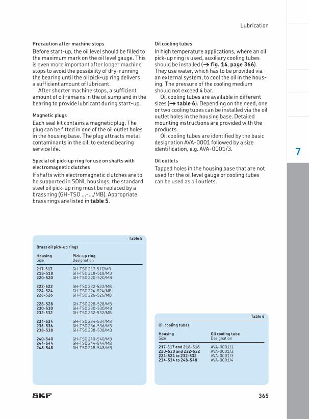
Oil cooling tubesIn high temperature applications, where an oil pick-up ring is used, auxiliary cooling tubes should be installed († fig. 14, page 366). They use water, which has to be provided via an external system, to cool the oil in the hous-ing. The pressure of the cooling medium should not exceed 4 bar.
Oil cooling tubes are available in different sizes († table 6). Depending on the need, one or two cooling tubes can be installed via the oil outlet holes in the housing base. Detailed mounting instructions are provided with the products.
Oil cooling tubes are identified by the basic designation AVA-0001 followed by a size identification, e.g. AVA-0001/3.
Oil outletsTapped holes in the housing base that are not used for the oil level gauge or cooling tubes can be used as oil outlets.
Table 6
Oil cooling tubes
Housing Size
Oil cooling tubeDesignation
217-517 and 218-518 AVA-0001/1220-520 and 222-522 AVA-0001/2224-524 to 232-532 AVA-0001/3234-534 to 248-548 AVA-0001/4
365
7
Split plummer block housings SONL series
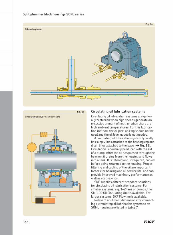
Fig. 14
Oil cooling tubes
Circulating oil lubrication systemsCirculating oil lubrication systems are gener-ally preferred when high speeds generate an excessive amount of heat, or when there are high ambient temperatures. For this lubrica-tion method, the oil pick-up ring should not be used and the oil level gauge is not needed.
A circulating oil lubrication system typically has supply lines attached to the housing cap and drain lines attached to the base († fig. 15). Circulation is normally produced with the aid of a pump. After the oil has passed through the bearing, it drains from the housing and flows into a tank. It is filtered and, if required, cooled before being returned to the housing. Proper filtering and cooling of the oil are important factors for bearing and oil service life, and can provide improved machinery performance as well as cost savings.
SKF supplies different standard solutions for circulating oil lubrication systems. For smaller systems, e.g. 1–2 fans or pumps, the SM-100 Oil Circulating Unit is available. For larger systems, SKF Flowline is available.
Relevant abutment dimensions for connect-ing a circulating oil lubrication system to an SONL housing are listed in table 7.
Fig. 15
Circulating oil lubrication system
366
Lubrication
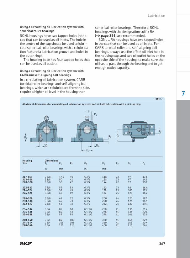
Using a circulating oil lubrication system with spherical roller bearingsSONL housings have two tapped holes in the cap that can be used as oil inlets. The hole in the centre of the cap should be used to lubri-cate spherical roller bearings with a relubrica-tion feature (a lubrication groove and holes in the outer ring).
The housing base has four tapped holes that can be used as oil outlets.
Using a circulating oil lubrication system with CARB and self-aligning ball bearingsIn a circulating oil lubrication system, CARB toroidal roller bearings and self-aligning ball bearings, which are relubricated from the side, require a higher oil level in the housing than
spherical roller bearings. Therefore, SONL housings with the designation suffix RA († page 356) are recommended.
SONL .. RA housings have two tapped holes in the cap that can be used as oil inlets. For CARB toroidal roller and self-aligning ball bearings, always use the offset oil inlet hole in the housing cap, and two oil outlet holes on the opposite side of the housing, to make sure the oil has to pass through the bearing and to get enough outlet capacity.
Table 7
Abutment dimensions for circulating oil lubrication systems and oil bath lubrication with a pick-up ring
Housing DimensionsSize PG P1 P2 RG R1 R2 O1 O2
– in. mm in. mm
217-517 G 3/8 47,5 40 G 3/4 118 22 97 138218-518 G 3/8 50 41 G 3/4 128 22 97 142220-520 G 3/8 50 47 G 3/4 144 22 97 150
222-522 G 3/8 55 53 G 3/4 162 23 98 163224-524 G 3/8 55 65 G 3/4 178 25 100 179226-526 G 3/8 60 69 G 3/4 192 25 120 184
228-528 G 3/8 65 72 G 3/4 200 26 121 187230-530 G 3/8 65 73 G 3/4 220 26 121 187232-532 G 3/8 65 78 G 3/4 252 26 121 196
234-534 G 3/4 85 88 G 1.1/2 268 41 136 215236-536 G 3/4 85 93 G 1.1/2 278 41 136 220238-538 G 3/4 85 98 G 1.1/2 298 41 166 225
240-540 G 3/4 85 100 G 1.1/2 320 41 166 229244-544 G 3/4 105 108 G 1.1/2 360 41 166 239248-548 G 3/4 110 115 G 1.1/2 400 41 216 244
O1
30
R2
RG
PGP1
R1
P2O2
367
7
Split plummer block housings SONL series
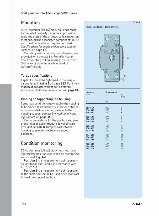
MountingSONL plummer (pillow) block housings must be mounted properly using the appropriate tools and state of the art mechanical mounting methods. All the associated components must also meet certain basic requirements († Specifications for shafts and housing support surfaces on page 45).
Mounting instructions for each housing are provided with the seal kit. For information about mounting rolling bearings, refer to the SKF bearing maintenance handbook or skf.com/mount.
Torque specificationsCap bolts should be tightened to the torque values listed in table 3 on page 363. For infor-mation about attachment bolts, refer to Attachment bolt recommendations on page XX.
Pinning or supporting the housingSome load conditions may require the housing to be pinned to its support surface or a stop to accommodate loads acting parallel to the housing support surface († Additional hous-ing support, on page 362).
Recommendations for the position and size of the holes to accommodate dowel pins are provided in table 8. Dimples cast into the housing base mark the recommended positions.
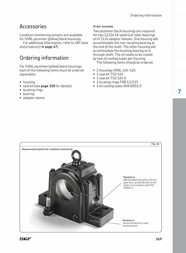
Condition monitoringSONL plummer (pillow) block housings have appropriate positions for condition monitoring sensors († fig. 16).
Position 1 is a measurement point perpen-dicular to the shaft and is in accordance with ISO 10816-1.
Position 2 is a measurement point parallel to the shaft and should be used when loads act toward the support surface.
Table 8
Position and size of dowel pin holes
Housing DimensionsSize J6 N4
max
– mm
217-517 290 6218-518 320 8220-520 350 8
222-522 370 8224-524 370 8226-526 390 8
228-528 430 8230-530 460 12232-532 480 12
234-534 530 20236-536 570 20238-538 640 20
240-540 630 20244-544 690 20248-548 800 20
J6
N4
368
Ordering information
AccessoriesCondition monitoring sensors are available for SONL plummer (pillow) block housings.
For additional information, refer to SKF tools and products († page 47).
Ordering informationFor SONL plummer (pillow) block housings, each of the following items must be ordered separately:
housing•seal kit• (see page 358 for details)locating rings•bearing•adapter sleeve•
Order exampleTwo plummer block housings are required for two 22224 EK spherical roller bearings on H 3124 adapter sleeves. One housing will accommodate the non-locating bearing at the end of the shaft. The other housing will accommodate the locating bearing on a through shaft. The oil needs to be cooled by two oil cooling tubes per housing.
The following items should be ordered:
2 housings • SONL 224-524 1 seal kit • TSO 5241 seal kit • TSO 524 A2 locating rings • FRB 12/2154 oil cooling tubes • AVA 0001/3
Fig. 16
Measurement points for condition monitoring
Position 1M8 threaded hole with a 30 mm spot-face, perpendicular to the shaft, in accordance with ISO 10816-1
Position 2Sensor position for axial measurement
369
7
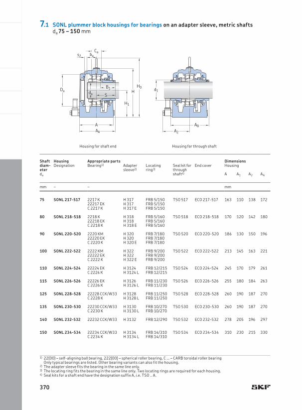
Shaft diam-eter
Housing Appropriate parts DimensionsDesignation Bearing1) Adapter
sleeve2)Locating ring3)
Seal kit for through shaft4)
End cover Housing
da A A1 A2 AA
mm – – mm
75 SONL 217-517 2217 K H 317 FRB 5/150 TSO 517 ECO 217-517 163 110 138 17222217 EK H 317 FRB 5/150C 2217 K H 317 E FRB 5/150
80 SONL 218-518 2218 K H 318 FRB 5/160 TSO 518 ECO 218-518 170 120 142 18022218 EK H 318 FRB 5/160C 2218 K H 318 E FRB 5/160
90 SONL 220-520 2220 KM H 320 FRB 7/180 TSO 520 ECO 220-520 186 130 150 19622220 EK H 320 FRB 7/180C 2220 K H 320 E FRB 7/180
100 SONL 222-522 2222 KM H 322 FRB 9/200 TSO 522 ECO 222-522 213 145 163 22122222 EK H 322 FRB 9/200C 2222 K H 322 E FRB 9/200
110 SONL 224-524 22224 EK H 3124 FRB 12/215 TSO 524 ECO 224-524 245 170 179 261C 2224 K H 3124 L FRB 12/215
115 SONL 226-526 22226 EK H 3126 FRB 11/230 TSO 526 ECO 226-526 255 180 184 263C 2226 K H 3126 L FRB 11/230
125 SONL 228-528 22228 CCK/W33 H 3128 FRB 11/250 TSO 528 ECO 228-528 260 190 187 270C 2228 K H 3128 L FRB 11/250
135 SONL 230-530 22230 CCK/W33 H 3130 FRB 10/270 TSO 530 ECO 230-530 260 190 187 270C 2230 K H 3130 L FRB 10/270
140 SONL 232-532 22232 CCK/W33 H 3132 FRB 12/290 TSO 532 ECO 232-532 278 205 196 297
150 SONL 234-534 22234 CCK/W33 H 3134 FRB 14/310 TSO 534 ECO 234-534 310 230 215 330C 2234 K H 3134 L FRB 14/310
1) 22(00) – self-aligning ball bearing, 222(00) – spherical roller bearing, C … – CARB toroidal roller bearing Only typical bearings are listed. Other bearing variants can also fit the housing.
2) The adapter sleeve fits the bearing in the same line only.3) The locating ring fits the bearing in the same line only. Two locating rings are required for each housing.4) Seal kits for a shaft end have the designation suffix A, i.e. TSO .. A.
H
H1
H0
Cabas2
Da
AAA
S
B1da
Housing for shaft end Housing for through shaft
d1
ABA2
7.1 SONL plummer block housings for bearings on an adapter sleeve, metric shaftsda 75 – 150 mm
370
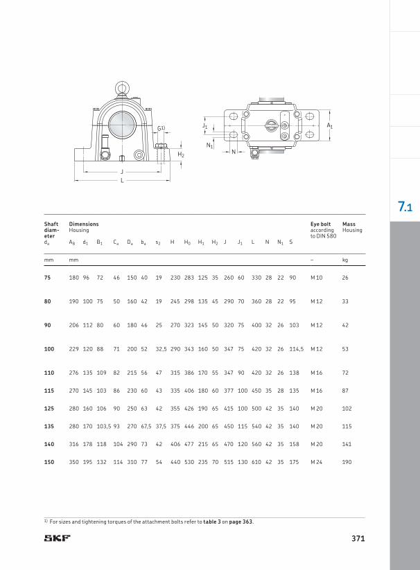
Shaft diam -eter
Dimensions Eye bolt MassHousing according
to DIN 580Housing
da AB d1 B1 Ca Da ba s2 H H0 H1 H2 J J1 L N N1 S
mm mm – kg
75 180 96 72 46 150 40 19 230 283 125 35 260 60 330 28 22 90 M 10 26
80 190 100 75 50 160 42 19 245 298 135 45 290 70 360 28 22 95 M 12 33
90 206 112 80 60 180 46 25 270 323 145 50 320 75 400 32 26 103 M 12 42
100 229 120 88 71 200 52 32,5 290 343 160 50 347 75 420 32 26 114,5 M 12 53
110 276 135 109 82 215 56 47 315 386 170 55 347 90 420 32 26 138 M 16 72
115 270 145 103 86 230 60 43 335 406 180 60 377 100 450 35 28 135 M 16 87
125 280 160 106 90 250 63 42 355 426 190 65 415 100 500 42 35 140 M 20 102
135 280 170 103,5 93 270 67,5 37,5 375 446 200 65 450 115 540 42 35 140 M 20 115
140 316 178 118 104 290 73 42 406 477 215 65 470 120 560 42 35 158 M 20 141
150 350 195 132 114 310 77 54 440 530 235 70 515 130 610 42 35 175 M 24 190
1) For sizes and tightening torques of the attachment bolts refer to table 3 on page 363.
G1)
H2
JL
A1
N1
J1
N
371
7.1
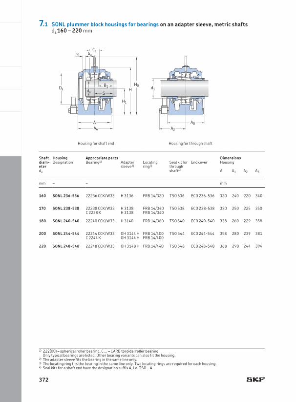
160 SONL 236-536 22236 CCK/W33 H 3136 FRB 14/320 TSO 536 ECO 236-536 320 240 220 340
170 SONL 238-538 22238 CCK/W33 H 3138 FRB 14/340 TSO 538 ECO 238-538 330 250 225 350C 2238 K H 3138 FRB 14/340
180 SONL 240-540 22240 CCK/W33 H 3140 FRB 14/360 TSO 540 ECO 240-540 338 260 229 358
200 SONL 244-544 22244 CCK/W33 OH 3144 H FRB 14/400 TSO 544 ECO 244-544 358 280 239 381C 2244 K OH 3144 H FRB 14/400
220 SONL 248-548 22248 CCK/W33 OH 3148 H FRB 14/440 TSO 548 ECO 248-548 368 290 244 394
Housing for shaft end Housing for through shaft
Shaft dia m-eter
Housing Appropriate parts DimensionsDesignation Bearing1) Adapter
sleeve2)Locating ring3)
Seal kit for through shaft4)
End cover Housing
da A A1 A2 AA
mm – – mm
1) 222(00) – spherical roller bearing, C … – CARB toroidal roller bearing Only typical bearings are listed. Other bearing variants can also fit the housing.
2) The adapter sleeve fits the bearing in the same line only.3) The locating ring fits the bearing in the same line only. Two locating rings are required for each housing.4) Seal kits for a shaft end have the designation suffix A, i.e. TSO .. A.
H
H1
H0
Cabas2
Da
AAA
S
B1da
d1
ABA2
7.1 SONL plummer block housings for bearings on an adapter sleeve, metric shaftsda 160 – 220 mm
372
Shaft diam- eter
Dimensions Eye bolt MassHousing according
to DIN 580Housing
da AB d1 B1 Ca Da ba s2 H H0 H1 H2 J J1 L N N1 S
mm mm – kg
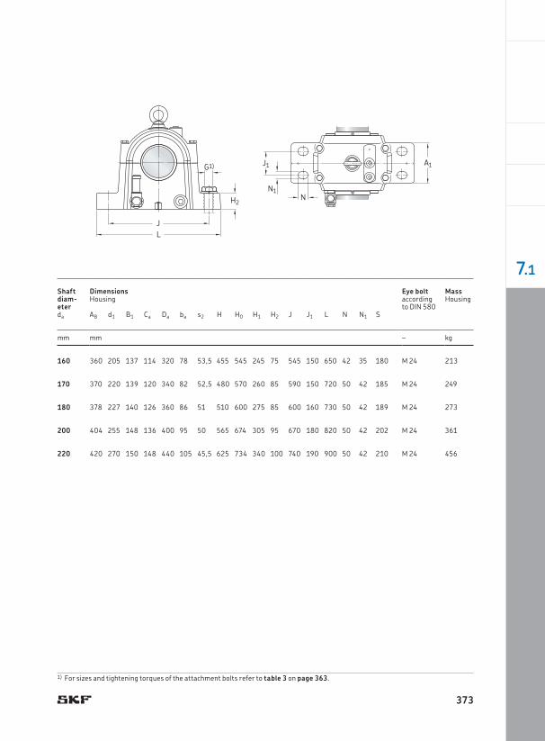
160 360 205 137 114 320 78 53,5 455 545 245 75 545 150 650 42 35 180 M 24 213
170 370 220 139 120 340 82 52,5 480 570 260 85 590 150 720 50 42 185 M 24 249
180 378 227 140 126 360 86 51 510 600 275 85 600 160 730 50 42 189 M 24 273
200 404 255 148 136 400 95 50 565 674 305 95 670 180 820 50 42 202 M 24 361
220 420 270 150 148 440 105 45,5 625 734 340 100 740 190 900 50 42 210 M 24 456
G1)
H2
JL
A1
N1
J1
N
1) For sizes and tightening torques of the attachment bolts refer to table 3 on page 363.
373
7.1
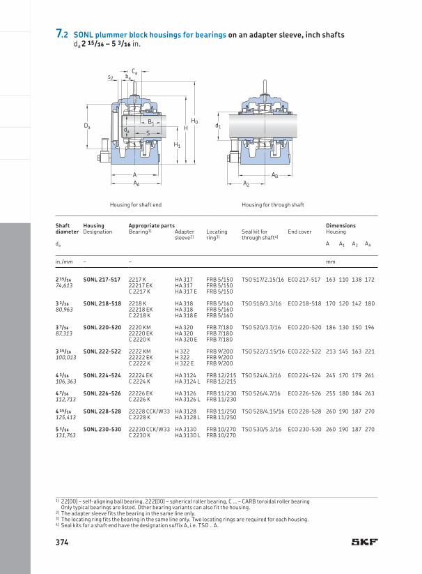
1) 22(00) – self-aligning ball bearing, 222(00) – spherical roller bearing, C … – CARB toroidal roller bearing Only typical bearings are listed. Other bearing variants can also fit the housing.
2) The adapter sleeve fits the bearing in the same line only.3) The locating ring fits the bearing in the same line only. Two locating rings are required for each housing.4) Seal kits for a shaft end have the designation suffix A, i.e. TSO .. A.
2 15/16 SONL 217-517 2217 K HA 317 FRB 5/150 TSO 517/2.15/16 ECO 217-517 163 110 138 17274,613 22217 EK HA 317 FRB 5/150
C 2217 K HA 317 E FRB 5/150
3 3/16 SONL 218-518 2218 K HA 318 FRB 5/160 TSO 518/3.3/16 ECO 218-518 170 120 142 18080,963 22218 EK HA 318 FRB 5/160
C 2218 K HA 318 E FRB 5/160
3 7/16 SONL 220-520 2220 KM HA 320 FRB 7/180 TSO 520/3.7/16 ECO 220-520 186 130 150 19687,313 22220 EK HA 320 FRB 7/180
C 2220 K HA 320 E FRB 7/180
3 15/16 SONL 222-522 2222 KM H 322 FRB 9/200 TSO 522/3.15/16 ECO 222-522 213 145 163 221100,013 22222 EK H 322 FRB 9/200
C 2222 K H 322 E FRB 9/200
4 3/16 SONL 224-524 22224 EK HA 3124 FRB 12/215 TSO 524/4.3/16 ECO 224-524 245 170 179 261106,363 C 2224 K HA 3124 L FRB 12/215
4 7/16 SONL 226-526 22226 EK HA 3126 FRB 11/230 TSO 526/4.7/16 ECO 226-526 255 180 184 263112,713 C 2226 K HA 3126 L FRB 11/230
4 15/16 SONL 228-528 22228 CCK/W33 HA 3128 FRB 11/250 TSO 528/4.15/16 ECO 228-528 260 190 187 270125,413 C 2228 K HA 3128 L FRB 11/250
5 3/16 SONL 230-530 22230 CCK/W33 HA 3130 FRB 10/270 TSO 530/5.3/16 ECO 230-530 260 190 187 270131,763 C 2230 K HA 3130 L FRB 10/270
Shaft dia meter
Housing Appropriate parts DimensionsHousingDesignation Bearing1) Adapter
sleeve2)Locating ring3)
Seal kit for through shaft4)
End cover
da A A1 A2 AA
in./mm – – mm
Housing for shaft end Housing for through shaft
H
H1
H0
Cabas2
Da
AAA
S
B1da
d1
ABA2
7.2 SONL plummer block housings for bearings on an adapter sleeve, inch shaftsda 2 15/16 – 5 3/16 in.
374
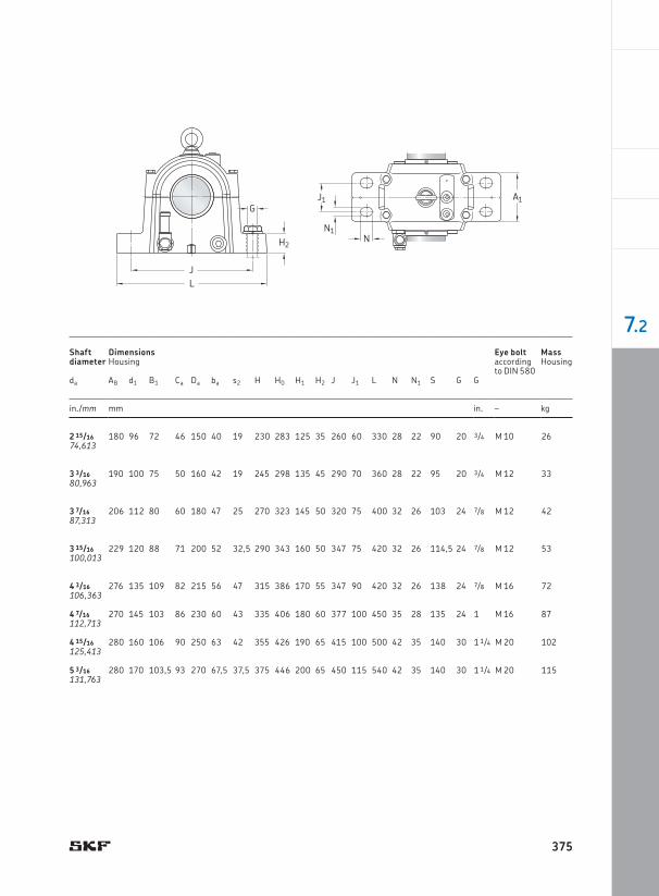
2 15/16 180 96 72 46 150 40 19 230 283 125 35 260 60 330 28 22 90 20 3/4 M 10 2674,613
3 3/16 190 100 75 50 160 42 19 245 298 135 45 290 70 360 28 22 95 20 3/4 M 12 3380,963
3 7/16 206 112 80 60 180 47 25 270 323 145 50 320 75 400 32 26 103 24 7/8 M 12 4287,313
3 15/16 229 120 88 71 200 52 32,5 290 343 160 50 347 75 420 32 26 114,5 24 7/8 M 12 53100,013
4 3/16 276 135 109 82 215 56 47 315 386 170 55 347 90 420 32 26 138 24 7/8 M 16 72106,363
4 7/16 270 145 103 86 230 60 43 335 406 180 60 377 100 450 35 28 135 24 1 M 16 87112,713
4 15/16 280 160 106 90 250 63 42 355 426 190 65 415 100 500 42 35 140 30 1 1/4 M 20 102125,413
5 3/16 280 170 103,5 93 270 67,5 37,5 375 446 200 65 450 115 540 42 35 140 30 1 1/4 M 20 115131,763
Shaft diameter
Dimensions Eye bolt MassHousing according
to DIN 580Housing
da AB d1 B1 Ca Da ba s2 H H0 H1 H2 J J1 L N N1 S G G
in./mm mm in. – kg
G
H2
JL
A1
N1
J1
N
375
7.2
1) 222(00) – spherical roller bearing, C … – CARB toroidal roller bearing Only typical bearings are listed. Other bearing variants can also fit the housing.
2) The adapter sleeve fits the bearing in the same line only.3) The locating ring fits the bearing in the same line only. Two locating rings are required for each housing.4) Seal kits for a shaft end have the designation suffix A, i.e. TSO .. A.
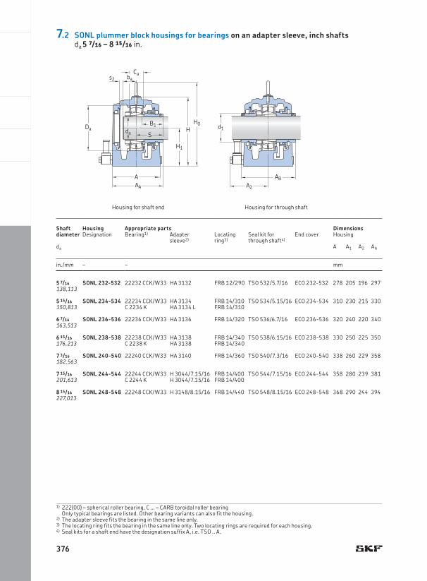
5 7/16 SONL 232-532 22232 CCK/W33 HA 3132 FRB 12/290 TSO 532/5.7/16 ECO 232-532 278 205 196 297138,113
5 15/16 SONL 234-534 22234 CCK/W33 HA 3134 FRB 14/310 TSO 534/5.15/16 ECO 234-534 310 230 215 330150,813 C 2234 K HA 3134 L FRB 14/310
6 7/16 SONL 236-536 22236 CCK/W33 HA 3136 FRB 14/320 TSO 536/6.7/16 ECO 236-536 320 240 220 340163,513
6 15/16 SONL 238-538 22238 CCK/W33 HA 3138 FRB 14/340 TSO 538/6.15/16 ECO 238-538 330 250 225 350176,213 C 2238 K HA 3138 FRB 14/340
7 3/16 SONL 240-540 22240 CCK/W33 HA 3140 FRB 14/360 TSO 540/7.3/16 ECO 240-540 338 260 229 358182,563
7 15/16 SONL 244-544 22244 CCK/W33 H 3044/7.15/16 FRB 14/400 TSO 544/7.15/16 ECO 244-544 358 280 239 381201,613 C 2244 K H 3044/7.15/16 FRB 14/400
8 15/16 SONL 248-548 22248 CCK/W33 H 3148/8.15/16 FRB 14/440 TSO 548/8.15/16 ECO 248-548 368 290 244 394227,013
Shaft diameter
Housing Appropriate parts DimensionsHousingDesignation Bearing1) Adapter
sleeve2)Locating ring3)
Seal kit for through shaft4)
End cover
da A A1 A2 AA
in./mm – – mm
Housing for shaft end
d1
ABA2
H
H1
H0
Cabas2
Da
AAA
S
B1da
Housing for through shaft
7.2 SONL plummer block housings for bearings on an adapter sleeve, inch shaftsda 5 7/16 – 8 15/16 in.
376
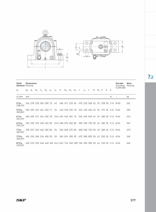
5 7/16 316 178 118 104 290 73 42 406 477 215 65 470 120 560 42 35 158 30 1 1/4 M 20 141138,113
5 15/16 350 195 132 114 310 77 54 440 530 235 70 515 130 610 42 35 175 30 1 1/4 M 24 190150,813
6 7/16 360 205 137 114 320 78 53,5 455 545 245 75 545 150 650 42 35 180 30 1 1/4 M 24 213163,513
6 15/16 370 220 139 120 340 82 52,5 480 570 260 85 590 150 720 50 42 185 36 1 1/2 M 24 249176,213
7 3/16 378 227 140 126 360 86 51 510 600 275 85 600 160 730 50 42 189 36 1 1/2 M 24 273182,563
7 15/16 404 255 148 136 400 95 50 565 674 305 95 670 180 820 50 42 202 36 1 1/2 M 24 361201,613
8 15/16 420 270 150 148 440 105 45,5 625 734 340 100 740 190 900 50 42 210 36 1 1/2 M 24 456227,013
Shaft diameter
Dimensions Housing
Eye bolt Massaccording to DIN 580
Housing
da AB d1 B1 Ca Da ba s2 H H0 H1 H2 J J1 L N N1 S G G
in./mm mm in. – kg
G
H2
JL
A1
N1
J1
N
377
7.2
Housing for shaft end
Shaft dia m-eter
Housing Appropriate parts Dimensions HousingDesignation Bearing1) Locating
ring2)Lock nut Locking
washerSeal kit for through shaft3)
End cover
da A A1 A2 AA AB d1
mm – – mm
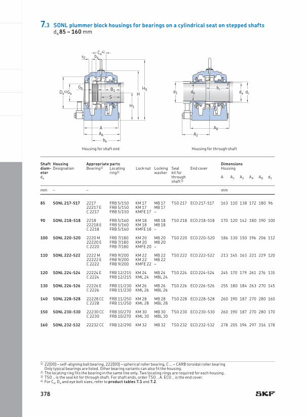
85 SONL 217-517 2217 FRB 5/150 KM 17 MB 17 TSO 217 ECO 217-517 163 110 138 172 180 9622217 E FRB 5/150 KM 17 MB 17C 2217 FRB 5/150 KMFE 17 –
90 SONL 218-518 2218 FRB 5/160 KM 18 MB 18 TSO 218 ECO 218-518 170 120 142 180 190 10022218 E FRB 5/160 KM 18 MB 18C 2218 FRB 5/160 KMFE 18 –
100 SONL 220-520 2220 M FRB 7/180 KM 20 MB 20 TSO 220 ECO 220-520 186 130 150 196 206 11222220 E FRB 7/180 KM 20 MB 20C 2220 FRB 7/180 KMFE 20 –
110 SONL 222-522 2222 M FRB 9/200 KM 22 MB 22 TSO 222 ECO 222-522 213 145 163 221 229 12022222 E FRB 9/200 KM 22 MB 22C 2222 FRB 9/200 KMFE 22 –
120 SONL 224-524 22224 E FRB 12/215 KM 24 MB 24 TSO 224 ECO 224-524 245 170 179 261 276 135C 2224 FRB 12/215 KML 24 MBL 24
130 SONL 226-526 22226 E FRB 11/230 KM 26 MB 26 TSO 226 ECO 226-526 255 180 184 263 270 145C 2226 FRB 11/230 KML 26 MBL 26
140 SONL 228-528 22228 CC FRB 11/250 KM 28 MB 28 TSO 228 ECO 228-528 260 190 187 270 280 160C 2228 FRB 11/250 KML 28 MBL 28
150 SONL 230-530 22230 CC FRB 10/270 KM 30 MB 30 TSO 230 ECO 230-530 260 190 187 270 280 170C 2230 FRB 10/270 KML 30 MBL 30
160 SONL 232-532 22232 CC FRB 12/290 KM 32 MB 32 TSO 232 ECO 232-532 278 205 196 297 316 178
1) 22(00) – self-aligning ball bearing, 222(00) – spherical roller bearing, C … – CARB toroidal roller bearing Only typical bearings are listed. Other bearing variants can also fit the housing.
2) The locating ring fits the bearing in the same line only. Two locating rings are required for each housing.3) TSO .. is the seal kit for through shaft. For shaft ends, order TSO .. A. ECO .. is the end cover.4) For Ca, Da and eye bolt sizes, refer to product tables 7.1 and 7.2.
dcbc
dbd1
ABA2
da
r
H
H1
H0
Ca4)bas2
r
Da4)
AAA
S
B1GaGb
bb
Housing for through shaft
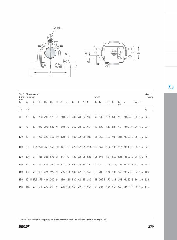
7.3 SONL plummer block housings for bearings on a cylindrical seat on stepped shaftsda 85 – 160 mm
378
G1)
H2
JL
A1
N1
J1
N
Shaft diam -eter
Dimensions Housing
MassShaft Housing
da B1 s2 H H0 H1 H2 J J1 L N N1 S ba bb bc db dc Ga Gb rmin
mm mm kg
85 72 19 230 283 125 35 260 60 330 28 22 90 40 130 105 83 91 M 85¥2 24 1,6 26
90 75 19 245 298 135 45 290 70 360 28 22 95 42 137 112 88 96 M 90¥2 24 1,6 33
100 80 25 270 323 145 50 320 75 400 32 26 103 46 150 123 98 106 M 100¥2 26 1,6 42
110 88 32,5 290 343 160 50 347 75 420 32 26 114,5 52 167 138 108 116 M 110¥2 28 1,6 52
120 109 47 315 386 170 55 347 90 420 32 26 138 56 194 164 118 126 M 120¥2 29 1,6 70
130 103 43 335 406 180 60 377 100 450 35 28 135 60 195 164 128 138 M 130¥2 31 1,6 84
140 106 42 355 426 190 65 415 100 500 42 35 140 63 203 170 138 148 M 140¥2 32 1,6 100
150 103,5 37,5 375 446 200 65 450 115 540 42 35 140 68 207,5 173 148 158 M 150¥2 34 1,6 113
160 118 42 406 477 215 65 470 120 560 42 35 158 73 231 195 158 168 M 160¥3 36 1,6 136
Eye bolt4)
1) For sizes and tightening torques of the attachment bolts refer to table 3 on page 363.
379
7.3
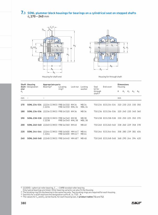
170 SONL 234-534 22234 CC/W33 FRB 14/310 KM 34 MB 34 TSO 234 ECO 234-534 310 230 215 330 350C 2234 FRB 14/310 KML 34 MBL 34
180 SONL 236-536 22236 CC/W33 FRB 14/320 KM 36 MB 36 TSO 236 ECO 236-536 320 240 220 340 360
190 SONL 238-538 22238 CC/W33 FRB 14/340 KM 38 MB 38 TSO 238 ECO 238-538 330 250 225 350 370C 2238 FRB 14/340 KML 38 MBL 38
200 SONL 240-540 22240 CC/W33 FRB 14/360 KM 40 MB 40 TSO 240 ECO 240-540 338 260 229 358 378
220 SONL 244-544 22244 CC/W33 FRB 14/400 HM 44 T MB 44 TSO 244 ECO 244-544 358 280 239 381 404C 2244 FRB 14/400 HM 44 T MB 44
240 SONL 248-548 22248 CC/W33 FRB 14/440 HM 48 T MB 48 TSO 248 ECO 248-548 368 290 244 394 420
1) 222(00) – spherical roller bearing, C … – CARB toroidal roller bearing Only typical bearings are listed. Other bearing variants can also fit the housing.
2) The locating ring fits the bearing in the same line only. Two locating rings are required for each housing.3) Seal kits for a shaft end have the designation suffix A, i.e. TSO .. A.4) The values for Ca and Da can be found, for each housing size, in product tables 7.1 and 7.2.
Housing for shaft end
dcbc
dbd1
ABA2
da
r
H
H1
H0
Ca4)bas2
r
Da4)
AAA
S
B1GaGb
bb
Housing for through shaft
Shaft dia m-eter
Housing Appropriate parts Dimensions HousingDesignation Bearing1) Locating
ring2)Lock nut Locking
washerSeal kit for through shaft3)
End cover
da A A1 A2 AA AB
mm – – mm
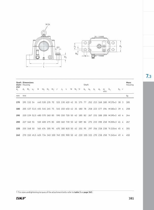
7.3 SONL plummer block housings for bearings on a cylindrical seat on stepped shaftsda 170 – 240 mm
380
170 195 132 54 440 530 235 70 515 130 610 42 35 175 77 252 213 168 180 M 170¥3 38 3 185
180 205 137 53,5 455 545 245 75 545 150 650 42 35 180 78 258 223 177 196 M 180¥3 39 4 208
190 220 139 52,5 480 570 260 85 590 150 720 50 42 185 82 267 231 188 208 M 190¥3 40 4 244
200 227 140 51 510 600 275 85 600 160 730 50 42 189 86 275 233 198 218 M 200¥3 41 4 267
220 255 148 50 565 674 305 95 670 180 820 50 42 202 95 297 256 218 238 Tr 220¥4 45 4 355
240 270 150 45,5 625 734 340 100 740 190 900 50 42 210 105 315 270 238 258 Tr 240¥4 49 4 450
G1)
H2
JL
A1
N1
J1
N
M 24
Shaft diam -eter
Dimensions Housing
MassShaft Housing
da d1 B1 s2 H H0 H1 H2 J J1 L N N1 S ba bb bc db dc Ga Gb rmin
mm mm kg
1) For sizes andtightening torques of the attachment bolts refer to table 3 on page 363.
381
7.3