spinning soccer ball trajectory - mathematics in · pdf filespinning soccer ball trajectory...
TRANSCRIPT
Spinning Soccer Ball Trajectory
Problem Presenter
Erhan Coskun1
Department of Mathematics, Karadeniz Technical University,
Trabzon, Turkey
Problem Statement
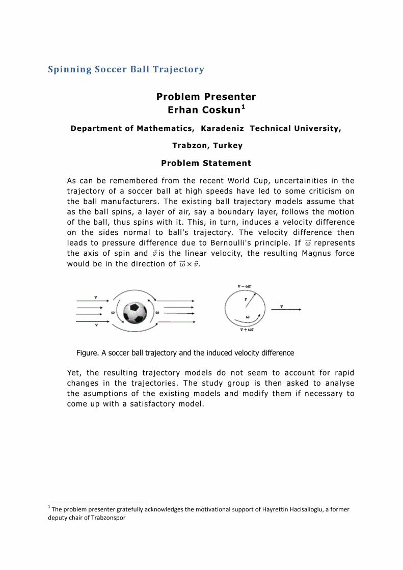
As can be remembered from the recent World Cup, uncertainit ies in the
trajectory of a soccer bal l at high speeds have led to some crit ic ism on
the ball manufacturers. The existing ball trajectory models assume that
as the bal l spins, a layer of air, say a boundary layer, fol lows the motion
of the ball, thus spins with it. This, in turn, induces a velocity difference
on the sides normal to ball 's trajectory. The velocity difference then
leads to pressure difference due to Bernoull i 's principle. If ω represents
the axis of spin and 𝑣 is the l inear velocity, the result ing Magnus force
would be in the direction of ω × 𝑣 .
Figure. A soccer ball trajectory and the induced velocity difference
Yet, the result ing trajectory models do not seem to account for rapid
changes in the trajectories. The study group is then asked to analyse
the asumptions of the existing models and modify them if necessary to
come up with a sat isfactory model.
1 The problem presenter gratefully acknowledges the motivational support of Hayrettin Hacisalioglu, a former
deputy chair of Trabzonspor
EM 2010
2
Report Authors
Wan Chen(OCCAM,Oxford Universi ty, UK)
Bahadır Çor(Middle East Technica l Universi ty, Ankara,Turkey )
Al i Konuralp(Celal Bayar Univers ity, Manisa, Turkey)
Tim Reis(OCCAM, Oxford Univers ity, UK)
Süleyman Şengül(Karadeniz Technical University, Trabzon, Turkey )
Contributors
Wan Chen(OCCAM,Oxford Universi ty, UK)
Bahadır Çor(Middle East Technica l Universi ty, Ankara,Turkey )
Al i Konuralp(Celal Bayar Univers ity, Manisa, Turkey)
Tim Reis(OCCAM, Oxford Univers ity, UK)
Süleyman Şengül(Karadeniz Technical University, Trabzon, Turkey )
Hamit Cihan 2(Karadeniz Technical Universi ty, Trabzon, Turkey)
John Ockendon(OCCAM, Oxford Univers ity, UK)
EM2010, 1st Euroasian Studygroup with Industry,
04-08 October, 2010
was organized by Karadeniz Technical University, Trabzon,
Turkey .
2 Hamit Cihan, a faculty member in Physical Education and Sport Department, KTU, who is also affiliated with
Trabzonspor has provided valuable technical assistance to the studygroup upon the request of Hayrettin Hacisalihoglu, a former deputy Chair of Trabzonspor.
EM 2010
3
Content
Abstrac t . . . . . . . . . . . . . . . . . . . . . . . . . . . . . . . . . . . . . . . . . . . . . . . . . . . . . . . . . . . . . . . . . . . . . . . . . . . . . . . . . . . . . . . . . . . . . . . . . . . . . . . . . . . . . . . . . . . . . . . 4
1. S tatement of the prob lem . . . . . . . . . . . . . . . . . . . . . . . . . . . . . . . . . . . . . . . . . . . . . . . . . . . . . . . . . . . . . . . . . . . . . . . . . . . . . . . . . . . . . . . . . . . . 4
2. Introduct ion and background . . . . . . . . . . . . . . . . . . . . . . . . . . . . . . . . . . . . . . . . . . . . . . . . . . . . . . . . . . . . . . . . . . . . . . . . . . . . . . . . . . . . . . . . 5
3. Observat ions . . . . . . . . . . . . . . . . . . . . . . . . . . . . . . . . . . . . . . . . . . . . . . . . . . . . . . . . . . . . . . . . . . . . . . . . . . . . . . . . . . . . . . . . . . . . . . . . . . . . . . . . . . . . . 8
4. The proposed mode l . . . . . . . . . . . . . . . . . . . . . . . . . . . . . . . . . . . . . . . . . . . . . . . . . . . . . . . . . . . . . . . . . . . . . . . . . . . . . . . . . . . . . . . . . . . . . . . . . . . 9
5. Resu l ts : Tra jec tory o f the ba l l . . . . . . . . . . . . . . . . . . . . . . . . . . . . . . . . . . . . . . . . . . . . . . . . . . . . . . . . . . . . . . . . . . . . . . . . . . . . . . . . . . . . 10
6. D iscuss ion . . . . . . . . . . . . . . . . . . . . . . . . . . . . . . . . . . . . . . . . . . . . . . . . . . . . . . . . . . . . . . . . . . . . . . . . . . . . . . . . . . . . . . . . . . . . . . . . . . . . . . . . . . . . . . 12
Acknowledgments . . . . . . . . . . . . . . . . . . . . . . . . . . . . . . . . . . . . . . . . . . . . . . . . . . . . . . . . . . . . . . . . . . . . . . . . . . . . . . . . . . . . . . . . . . . . . . . . . . . . . . . . . 14
References . . . . . . . . . . . . . . . . . . . . . . . . . . . . . . . . . . . . . . . . . . . . . . . . . . . . . . . . . . . . . . . . . . . . . . . . . . . . . . . . . . . . . . . . . . . . . . . . . . . . . . . . . . . . . . . . . . 14
EM 2010
4
Abstract In this study the trajectory of a soccer ball is investigated using a
dynamical system that takes the Magnus, drag and gravitational forces into
consideration. In particular, close attent ion is paid to the trajectory of a
soccer ball under an init ial rotational kick. We first note that bal ls which
are rather smooth, such as the Jabulani, typically hit the cr it ical condit ions
of the so-cal led “drag-crisis" at crutial moments in a game of soccer, such
as during a free-kick, so that “knuckling" is more pronounced. We then
propose a simpli f ied system consist ing of three ordinary differential
equations describing horizontal and vertical acceleration and rotation rate
as functions of the forces on the ball, and of its “roughness". We f ind that
the parameter controll ing the roughness to play a cr it ical role in the
result ing trajectory. In particular, when this parameter is small, as we
assume it to be for soccer balls such as the Jabulani, it is possible for the
trajectory to develop two turning points, suggest ing that the bal l could
appear to “bounce" in mid -f l ight.
1. Statement of the problem
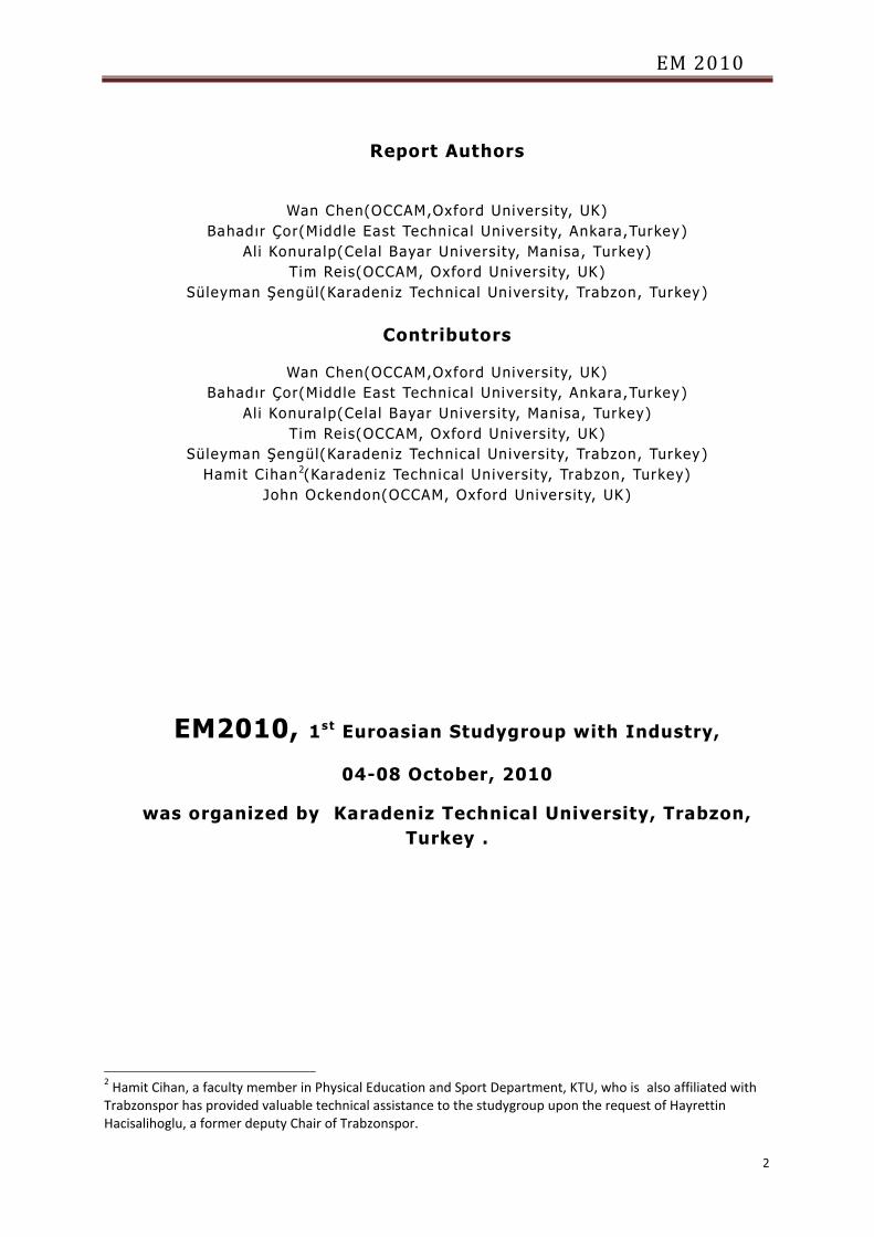
As can be remembered from the 2010 FIFA World Cup, uncertainties in the
trajectory of the Jabulani soccer bal l has resulted in some crit icism of the
ball ’s design. Existing models for the trajectory of spinning soccer balls
assume that a layer of air, known as a boundary layer, fol lows the motion
of the bal l, and thus spins with it. This, in turn, induces a velocity
difference on the sides normal to the bal l ’s trajectory. The velocity
difference results in a pressure difference due to Bernoull i ’s principle. If ω
represents the axis of spin and v denotes the ( l inear) velocity, then the
result ing Magnus force would be in the direction of ω × v. However, the
result ing models do not sufficiently account for rapid changes in the
trajectories. The study group is thus asked to analyse the assumptions of
the existing models and assess their validity.
Figure 1: Velocity of a soccer ball .
EM 2010
5
2. Introduction and background
When a tradit ional soccer bal l starts its descent, it is expected, due to the
effect of gravity, to fa l l to the pitch without any reversal of its vertical
velocity. However, the Jabulani has been observed to behave somewhat
differently under certain condit ions - after a forceful kick, soccer players
have witnessed the ball moving upwards again shortly afte r the beginning
of its fal l; in other words, the ball ’s trajectory could have more that one
maxima - “ it ’s l ike putting the brakes on, but putting them on unevenly".
This could clearly affect a player ’s abil ity to control the fl ight of the ball.
From a goa lkeeper’s viewpoint, an approaching ball may suddenly appear
to change its direct ion in a way grossly unpredictable. We believe this kind
of phenomenon, arguably a much more common (and unwanted) attribute
of the Jabulani, is related to the amount of, and indeed pattern of, the
surface roughness of the ball. This in turn wil l affect the posit ion of the
separation points of the boundary layers, which are a feature rotating
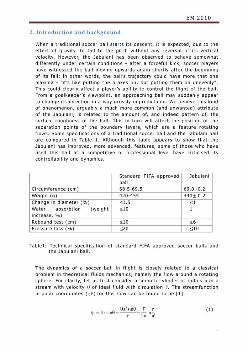
flows. Some specifications of a tradit ional soccer ball and the Jabulani bal l
are compared in Table 1. Although this table appears to show that the
Jabulani has improved, more advanced, features, some of those who have
used this bal l at a competit ive or professional level have cr it ic ised its
controllabil ity and dynamics.
Standard FIFA approved
ball
Jabulani
Circumference (cm) 68.5-69.5 69.0±0.2
Weight (g) 420-455 440± 0.2
Change in diameter (%) ≤1.5 ≤1
Water absorbt ion (weight
increase, %)
≤10 1
Rebound test (cm) ≤10 ≤6
Pressure loss (%) ≤20 ≤10
Table1: Technical specification of s tandard FIFA approved soccer bal ls and the Jabulani ball.
The dynamics of a soccer bal l in fl ight is closely related to a classical
problem in theoret ical f luids mechanics, namely the f low around a rotating
sphere. For clar ity, let us first consider a smooth cylinder of radius a in a
stream with velocity U of ideal f luid with circulation Γ. The streamfunction
in polar coordinates (r, θ) for this flow can be found to be [1]
ψ = Ur sinθ−Ua2sinθ
r−
Γ
2πln
r
a,
(1)
EM 2010
6
If Γ ≤ 4πUa, there is a stagnation point on the cylinder and from Bernoull i ’s
principle it can be found that the drag FD and l ift FL forces are respect ively
given by
FD = 0, (2)
FL = −ρUΓ, (3)
where ρ is the density of the fluid. The l ift force can be understood as
fol lows: The circulation gives higher speed on one side of the cylinder (c.f
Figure 1). This higher speed is associated with lower pressure p since
p +1
2ρv2 = constant ,
(4)
and hence there is a force, known sometimes as the Magnus force, from
the high pressure (slow speed) side to the low pressure (fast speed) side.
So a soccer bal l kicked with suff i c ient spin wi l l generate l ift and rise. As
the ball slows its trajectory wil l be altered by the forces acting on it and
curls upon descent, as is observed in, for example, free -kick taking.
However, there are considerable viscous effects near the boundary of the
cylinder/sphere and hence Bernoull i ’s principle loses its val id ity. The body
may be subjected to turbulence, which can affect it ’s fl ight. Note that
although this alters the forces on the sphere, the physical intuit ion
remains. In this more complicated, yet more interest ing and real ist ic case,
the forces acting on the body are given by
FD = −1
2CdρA v 2ex ,
(5)
FM = −2CdρA v ey , (6)
Fg = Mg , (7)
where Cd is the drag coefficient, ρ is the fluid (air) density, A is the cross-
sect ional area of the ball, M is its mass, and g = 9.8 m/s2 is the gravity. The
drag coefficient Cd wil l depend on the properties of the ball and the
Reynolds number, Re, which is defined to be
Re = v L
v ,
(8)
where v is the f luid ’s kinematic viscosity and L is a characterist ic length,
which is taken to be the diameter of the ball. Moreover, at high Reynolds
EM 2010
7
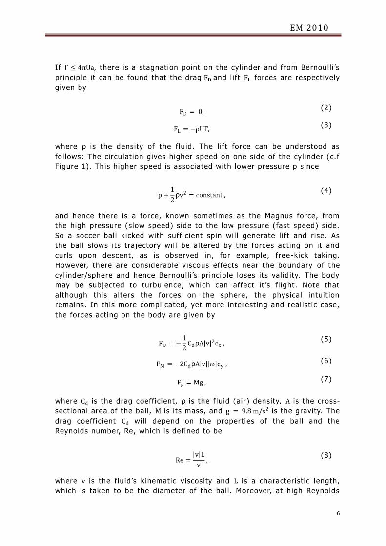
numbers, boundary layers are present and flow separation is observed at
two separation points on the cylinder. In the absence of rotation these
separation points are symmetric with respect to the azimuthal coordinate
(see Figure 2, for example) and asymmetric when the cylinder/sphere is
spinning.
The displacement of the l ine of separation has a considerable effect on the
flow. In Figure 2 the separation points are close together so that the
turbulent wake beyond the body is contracted. This, in turn, reduces the
drag experienced by the body. Thus the onset of turbulence in the
boundary layer at larger Reynolds numbers is accompanied by a dec rease
in the drag coefficient. When the separation points are further apart the
drag increases significant ly (this is sometimes referred to as the drag
crisis [2]). In other words, causing a turbulent boundary layer to form on
the front surface significant ly reduces the sphere’s drag. In terms of
soccer balls, for a given diameter and velocity the manufacturer has just
one opt ion to encourage this transit ion: to make the surface rough in
order to create turbulence. We note that the same principal applies to golf
balls.
Although the mathematics and physics of rotating bodies is complicated,
we develop a simple dynamical system to describe the trajectory of such a
body that is affected by acceleration, spin, and surface roughness. Despite
its simplicity it can highlight the motion of a soccer bal l and the cr it ical
features that can cause unexpected or unwanted behaviour. We point the
interested reader to other works in this field [4, 5, 6, 7].
Figure 2: The general character of flow over a cyl inder at high
Reynolds numbers.
The remained of this report is structured as follows: In Section 3 we note
some observations we have made related to the fl ight of the Jabulani; in
Section 4 we present the dynamical system for the trajectory of a rotat ing
cylinder; the results are presented in Section 5 and a summary is drawn in
Section 6.
EM 2010
8
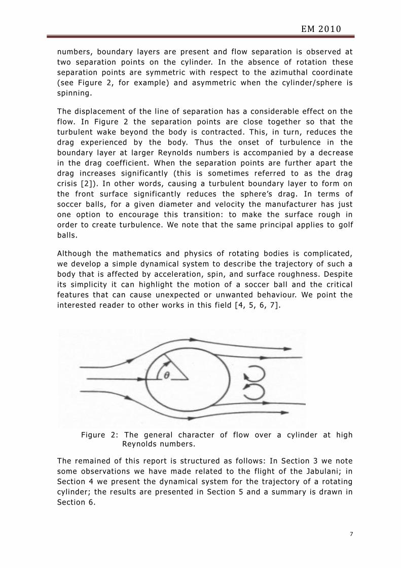
3. Observations The relationship between the drag coeffic ient and Reynolds number for
smooth and rough spherical bodies is shown in Figure 3.
Figure 3: Drag coefficient for rough and smooth spheres.
Tradit ional soccer balls are not smooth. Although some surface roughness
has been added to the Jabulani it is st i l l a lot smoother than other soccer
balls. It is therefore reasonable to assume that the dynamics of each wi l l
differ, especial ly when rotation is included. Also, tradit ional bal ls have a
hexagonal design and at small spin the stitching can cause an a
asymmetric flow field, causing the ball to “knuckle"; that is it may be
pushed a small amount in a given direction even when the ball has l itt le
rotation. The Jabulani has no stitching and the speed at which knuckling
may occur is 20 − 30 km/h faster with the Jabulani than with tradit ional
balls [3]. This coincides with the average speed of a free kick, and hence
the pronounced vis ib i l ity of chaotic trajectories with the Jabulani.
During its f l ight, the highest measured speed of a soccer bal l kicked by a
player in an official game is 140 km/h. A typical powerful shot kicked by a
professional player (during a free -kick, for example) g ives the ball a speed
of about 100 km/h (about 30 m/s). With the known values of v (roughly
20 × 10−6 m2/s) and L, we calculate the Reynolds number in to be between
between 100 000 and 500 000. From Figure 3 we can see that the drag
coefficient of the rough bal l does not drop as dramatically as the smooth
one in this regime. Although the Jabulani does have some surface
EM 2010
9
roughness, it is st i l l considerably smoother than any other soccer ball.
Therefore the Jabulani may experience rapid changes in the forces acting
on it during high Reynolds number flows, such as during a free kick.
We also note that the distribution of surface roughness is l ikely to effect the
flow field around a rotating body. Old soccer bal ls may have st itching
which could potent ial ly alter the flow field, but the stitching is evenly
spread over the surface area. It is not obvious i f the small roughness that
has been added to the Jabulani is equal ly distr ibuted over the ball.
Indeed, an eye-ball examinat ion would suggest otherwise. Although this is
unl ikely to have an effect in most s ituat ions it may wel l be an important
factor that needs consideration when the ball is rotating at high Reynolds
numbers.
4. The proposed model
We developed a simple, idealised, dynamical system for the trajectory of a
cylindrical body that takes surface roughness into consideration. The
governing system is written as
x = −1
2mCdρAx x 2 + y 2 −
2ρAr
mCd y ω ,
(9)
y = −1
2mCdρAy x 2 + y 2 +
2ρAr
mCd x ω− g,
(10)
ω = −R
r x 2 + y 2ω,
(11)
subject to the fol lowing init ial condit ions:
x(0) = 0; x′(0) = 30, (12)
y(0) = 2; y′(0) = 0, (13)
The init ial condit ions for ω wi l l be discussed in the following section. In
the above, R is a parameter (assumed constant) describing the roughness
of the ball, r is the radius and x, y and ω are functions of t ime ( t). We
assume the drag coefficient undergoes a rapid change in the crit ical
Reynolds number regime and fit it using a cubic interpolation from Figure
3, that is
Cd = 0.0198 Re3
3−
7Re2
2+ 6Re + 0.457,
(14)
The other parameters were chosen according to t he physical
characterist ics:
EM 2010
10
m = 0.44 kg,
r = 0.1098 m,
ρ = 1.225 kgm−3 ,
A = 0.037875167 m2 ,
v = 2 × 10⁻⁵ m2s−1
The first two equat ions in our system my be viewed as statements of
Newton’s second law of motion, i.e force = mass×accelerat ion, where the
horizontal and vertical forces are taken from equations 5 and 6. Equation
(9) describes the horizontal acceleration in terms of the drag force. We
see that the equation for vertical motion, equation (10), has three terms;
the first two of these (which correspond to the Magnus, or l i f t, force) must
exceed the last (which is describing the action of gravity) i f there is to be
an upwards motion. It should also be noted that the second terms in
equations (9) and (10) depend on the rotation, ω, which itself depends on
the roughness parameter R.
5. Results: Trajectory of the ball
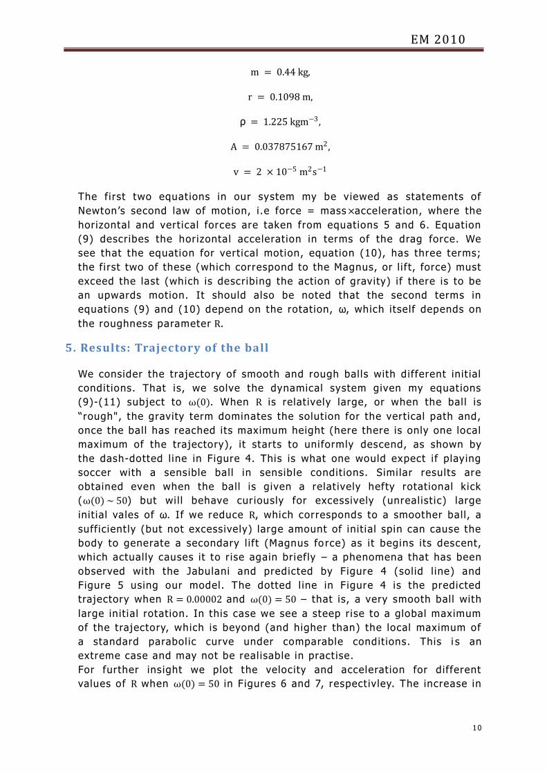
We consider the trajectory of smooth and rough balls with different init ial
condit ions. That is, we solve the dynamical system given my equat ions
(9)-(11) subject to ω(0). When R is relatively large, or when the bal l is
“rough", the gravity term dominates the solution for the vertical path and,
once the ball has reached its maximum height (here there is only one local
maximum of the trajectory), it starts to uniformly descend, as shown by
the dash-dotted l ine in Figure 4. This is what one would expect i f playing
soccer with a sensible ball in sensible condit ions. Simi lar results are
obtained even when the ball is given a relat ively hefty rotational kick
(ω(0) ~ 50) but wi l l behave curiously for excessively (unrealist ic) large
init ial vales of ω. If we reduce R, which corresponds to a smoother ball, a
sufficient ly (but not excessively) large amount of init ial spin can cause the
body to generate a secondary l ift (Magnus fo rce) as it begins its descent,
which actually causes it to r ise again briefly – a phenomena that has been
observed with the Jabulani and predicted by Figure 4 (solid l ine) and
Figure 5 using our model. The dotted l ine in Figure 4 is the predicted
trajectory when R = 0.00002 and ω(0) = 50 – that is, a very smooth ball with
large init ial rotation. In this case we see a steep rise to a global maximum
of the trajectory, which is beyond (and higher than) the local maximum of
a standard parabol ic curve under comparable condit ions. This i s an
extreme case and may not be real isable in pract ise.
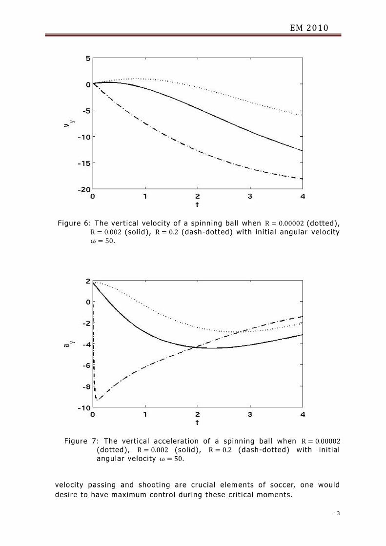
For further insight we plot the velocity and acceleration for different
values of R when ω(0) = 50 in Figures 6 and 7, respect ivley. The increase in
EM 2010
11
the velocity and decrese in acceleration when R is small is noteworthy
since it may be
Figure 4: The x − y trajectory of a spinning ball when R = 0.00002
(dotted), R = 0.002 (solid), R = 0.2 (dash-dotted) with init ial
angular velocity ω = 50.
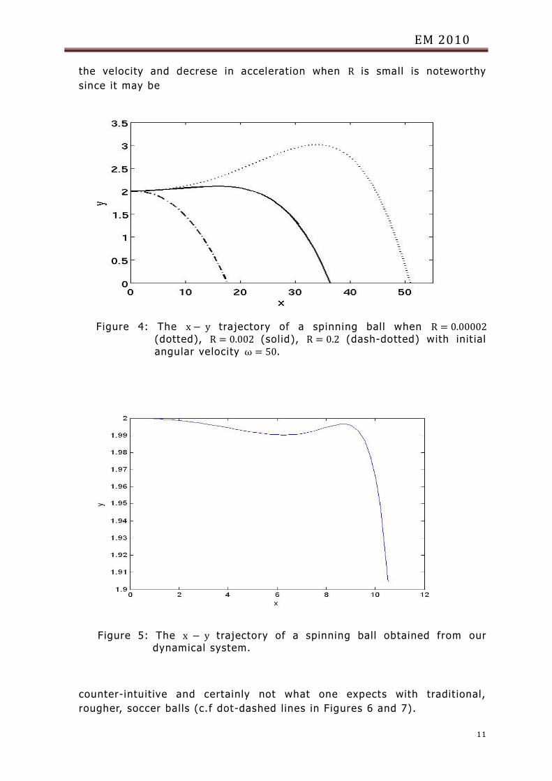
Figure 5: The x − y trajectory of a spinning ball obtained from our dynamical system.
counter-intuit ive and certainly not what one expects with tradit ional,
rougher, soccer balls (c.f dot-dashed l ines in Figures 6 and 7).
EM 2010
12
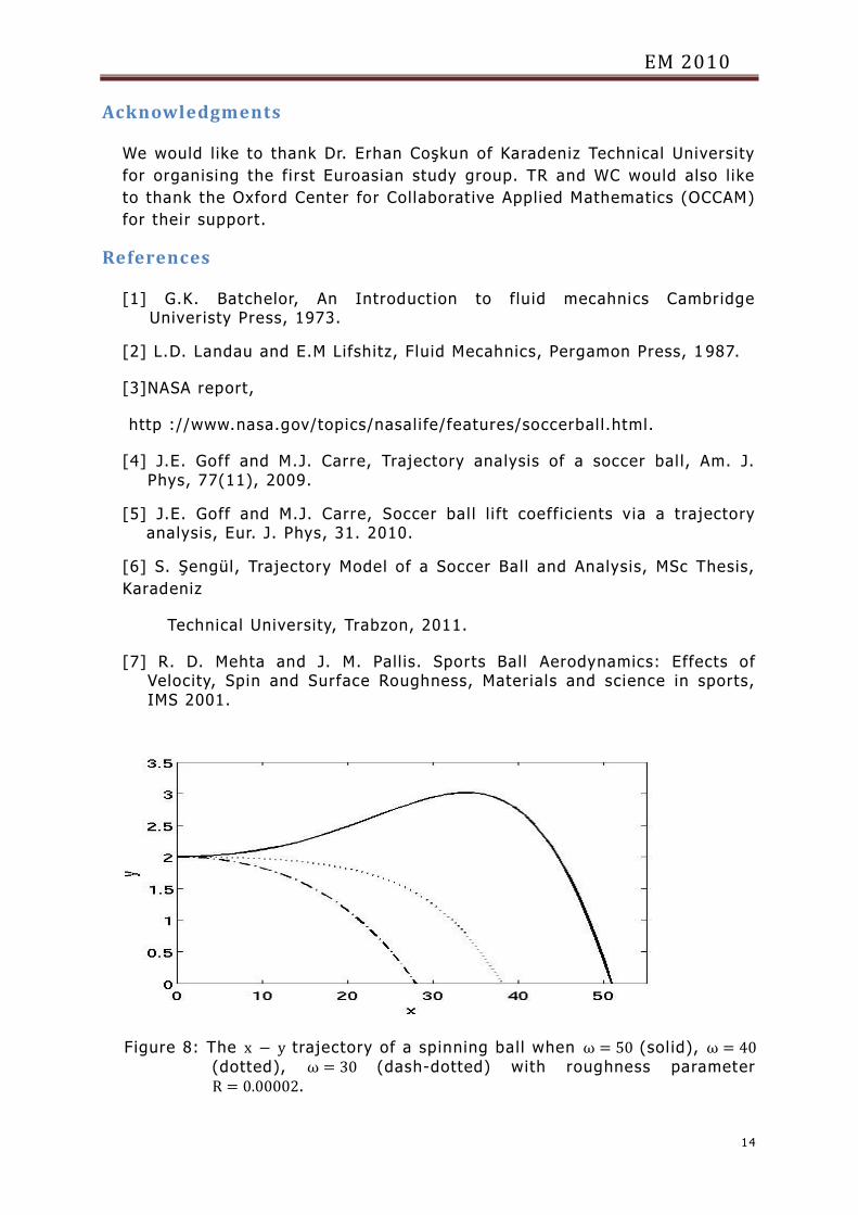
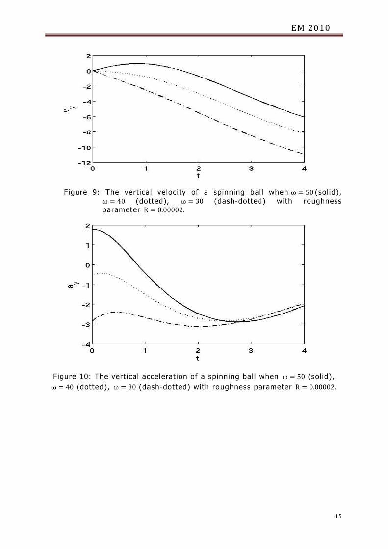
We mentioned above that the init ial condit ions (in partcular, the init ial
rotation) also affect the f l ight path, and this can be seen in Figures 8, 9
and 10. Figure 10 is particuarly enlightening since it shows the
complicated, highly non-linear behaviour of the acceleration for a smooth
ball, even when the init ial rotat ion is relatively small.
6. Discussion
We have proposed a dynamical system to predict the trajectory of a
cylindrical body subject to accelerat ion, spin, and surface roughness. We
have shown that the roughness (included through the parameter R) and
the init ial spin to be the crit ical factors responsible for the so-called
“knuckling" effect, and for unpredictable changes in a balls vertical
acceleration. This could offer some understanding to why the Jabulani, a
smoother-than-normal ball, exhibits somewhat unpredictable behaviour
under crucial condit ions such as free -kick taking, long-range passing, and
distance shooting. Physically, the roughness parameter R is related to not
only the surface structure of the bal l but also the separation points of the
boundary layer during rotational flow. Small R wil l be accompanied by
widely spaced separation points and a large turbulent wake, whereas a
larger R means the separat ion points wi l l be closer and the wake behind
the sphere narrower. A potential ly interesting further study could be to try
and quantify this relationship, perhaps by introducing a fourth equat ion for
the symmetry of separation or to include the “spread" of roughness (for
example, as noted above it is not clear i f the roughness purposeful ly
added to the Jabulani is suffic iently, o r evenly, distributed over the bal l ’s
surface). Perhaps a model with a variable R may also be enlightening. We
have also remarked that the forces on the Jabulani may undergo rapid
changes (more rapid than for rougher tradit ional balls) during a free kick,
which wi l l effect its fl ight kinematics. It is also worth mentioning that an
experimental study [3] revealed that the new ball fal ls v ict im to
“knuckling" at higher velocit ies than old soccer balls, which coincides with
the average maximum speed of fl ight during a free kick. It is unclear i f the
knuckling effects are stronger with the Jabulani, or just more readi ly
observed. Considering free kicks and high
EM 2010
13
Figure 6: The vert ical velocity of a spinning ball when R = 0.00002 (dotted),
R = 0.002 (sol id), R = 0.2 (dash-dotted) with init ial angular velocity
ω = 50.
Figure 7: The vert ical accelerat ion of a spinning bal l when R = 0.00002
(dotted), R = 0.002 (solid), R = 0.2 (dash-dotted) with init ial
angular velocity ω = 50.
velocity passing and shooting are crucial elements of soccer, one would
desire to have maximum control during these crit ical moments.
EM 2010
14
Acknowledgments
We would l ike to thank Dr. Erhan Coşkun of Karadeniz Technical University
for organising the first Euroasian study group. TR and WC would also l ike
to thank the Oxford Center for Collaborat ive Applied Mathematics (OCCAM)
for their support.
References
[1] G.K. Batchelor, An Introduct ion to fluid mecahnics Cambridge Univeristy Press, 1973.
[2] L.D. Landau and E.M Lifshitz, Fluid Mecahnics, Pergamon Press, 1 987.
[3]NASA report,
http ://www.nasa.gov/topics/nasali fe/features/soccerbal l.html.
[4] J.E. Goff and M.J. Carre, Trajectory analysis of a soccer bal l, Am. J. Phys, 77(11), 2009.
[5] J.E. Goff and M.J. Carre, Soccer bal l l i ft coefficients via a trajectory analysis, Eur. J. Phys, 31. 2010.
[6] S. Şengül, Trajectory Model of a Soccer Ball and Analysis, MSc Thesis,
Karadeniz
Technical University, Trabzon, 2011.
[7] R. D. Mehta and J. M. Pall is. Sports Ball Aerodynamics: Effects of Velocity, Spin and Surface Roughness, Materials and science in sports, IMS 2001.
Figure 8: The x − y trajectory of a spinning ball when ω = 50 (sol id), ω = 40
(dotted), ω = 30 (dash-dotted) with roughness parameter
R = 0.00002.
EM 2010
15
Figure 9: The vertical velocity of a spinning bal l when ω = 50 (solid),
ω = 40 (dotted), ω = 30 (dash-dotted) with roughness
parameter R = 0.00002.
Figure 10: The vertical acceleration of a spinning ball when ω = 50 (solid),
ω = 40 (dotted), ω = 30 (dash-dotted) with roughness parameter R = 0.00002.