specification to api specification 2c offshore …supplementary specification to api specification...
TRANSCRIPT
SPECIFICATION
S-618
DECEMBER 2018
Supplementary Specif ication to API Specification 2C Offshore Pedestal-mounted Cranes
Revision history
VERSION DATE AMENDMENTS
1.0 December 2018 Issued for publication
Acknowledgements This IOGP Specification was prepared by a Joint Industry Project 33 Standardization of Equipment Specifications for Procurement organized by IOGP with support by the World Economic Forum (WEF). Disclaimer
Whilst every effort has been made to ensure the accuracy of the information contained in this publication, neither IOGP nor any of its Members past present or future warrants its accuracy or will, regardless of its or their negligence, assume liability for any foreseeable or unforeseeable use made thereof, which liability is hereby excluded. Consequently, such use is at the recipient’s own risk on the basis that any use by the recipient constitutes agreement to the terms of this disclaimer. The recipient is obliged to inform any subsequent recipient of such terms. This publication is made available for information purposes and solely for the private use of the user. IOGP will not directly or indirectly endorse, approve or accredit the content of any course, event or otherwise where this publication will be reproduced.
Copyright notice
The contents of these pages are © International Association of Oil & Gas Producers. Permission is given to reproduce this report in whole or in part provided (i) that the copyright of IOGP and (ii) the sources are acknowledged. All other rights are reserved. Any other use requires the prior written permission of IOGP.
These Terms and Conditions shall be governed by and construed in accordance with the laws of England and Wales. Disputes arising here from shall be exclusively subject to the jurisdiction of the courts of England and Wales.

Supplementary Specification to API Specification 2C Offshore Pedestal-mounted Cranes
Page 1 of 25 S-618 December 2018
Foreword
This specification was prepared under a Joint Industry Project 33 (JIP33) “Standardization of Equipment Specifications for Procurement” organized by the International Oil & Gas Producers Association (IOGP) with the support from the World Economic Forum (WEF). Ten key oil and gas companies from the IOGP membership participated in developing this specification under JIP33 Phase 2 with the objective to leverage and improve industry level standardization for projects globally in the oil and gas sector. The work has developed a minimized set of supplementary requirements for procurement, with life cycle cost in mind, based on the ten participating members’ company specifications, resulting in a common and jointly approved specification, and building on recognized industry and international standards.
This specification has been developed in consultation with a broad user and supplier base to promote the opportunity to realize benefits from standardization and achieve significant cost reductions for upstream project costs. The JIP33 work groups performed their activities in accordance with IOGP’s Competition Law Guidelines (November 2014).
Recent trends in oil and gas projects have demonstrated substantial budget and schedule overruns. The Oil and Gas Community within the World Economic Forum (WEF) has implemented a Capital Project Complexity (CPC) initiative which seeks to drive a structural reduction in upstream project costs with a focus on industry-wide, non-competitive collaboration and standardization. The vision from the CPC industry is to standardize specifications for global procurement for equipment and packages, facilitating improved standardization of major projects across the globe. While individual oil and gas companies have been improving standardization within their own businesses, this has limited value potential and the industry lags behind other industries and has eroded value by creating bespoke components in projects.
This specification aims to significantly reduce this waste, decrease project costs and improve schedule through pre-competitive collaboration on standardization. This document defines the supplementary requirements to recognized industry standard API Specification 2C 7th Edition, 2012 including Errata 2013, Offshore Pedestal-mounted Cranes, which is indispensable for the application of this specification.
Following agreement of the relevant JIP33 work group and approval by the JIP33 Steering Committee, the IOGP Management Committee has agreed to the publication of this specification by IOGP. Where adopted by the individual operating companies, this specification and associated documentation aims to supersede existing company documentation for the purpose of industry-harmonized standardization.

Supplementary Specification to API Specification 2C Offshore Pedestal-mounted Cranes
Page 2 of 25 S-618 December 2018
Table of Contents
Foreword ............................................................................................................................................................. 1 Introduction ......................................................................................................................................................... 4 1 Scope ....................................................................................................................................................... 6 2 Normative References .............................................................................................................................. 6 3 Terms, Definitions and Abbreviations....................................................................................................... 6
3.1 Terms and Definitions .................................................................................................................... 6 3.2 Abbreviations.................................................................................................................................. 7 3.3 Units ............................................................................................................................................... 7
4 Documentation ......................................................................................................................................... 7 4.1 Manufacturer-supplied Documentation upon Purchase ................................................................. 7 4.2 Purchaser-supplied Information prior to Purchase ......................................................................... 8
5 Loads ........................................................................................................................................................ 8 5.2 Critical Components ....................................................................................................................... 8 5.4 In-service Loads ............................................................................................................................. 8
6 Structure ................................................................................................................................................... 9 6.1 General ........................................................................................................................................... 9 6.2 Pedestal, Kingpost, and Crane Supporting Foundation ................................................................. 9
7 Mechanical ............................................................................................................................................... 9 7.2 Critical Rigging Components .......................................................................................................... 9 7.3 Boom Hoist, Load Hoist, Telescoping, and Folding Boom Mechanisms ..................................... 10 7.4 Swing Mechanism ........................................................................................................................ 11 7.5 Power Plant .................................................................................................................................. 11
8 Ratings ................................................................................................................................................... 13 8.1 General ......................................................................................................................................... 13
9 Gross Overload Conditions .................................................................................................................... 13 9.1 General ......................................................................................................................................... 13 9.5 Gross Overload Protection System (GOPS) ................................................................................ 13
10 Human Factors-Health, Safety, and Environment .................................................................................. 15 10.1 Controls ........................................................................................................................................ 15 10.3 Miscellaneous Requirements and Equipment .............................................................................. 17 10.4 Lighting ......................................................................................................................................... 23
11 Manufacturing Requirements ................................................................................................................. 23 11.1 Material Requirements of Critical Components ........................................................................... 23 11.5 Interchangeability ......................................................................................................................... 23
12 Design Validation by Testing .................................................................................................................. 23 12.3 Operational Tests ......................................................................................................................... 23
13 Marking and Labelling ............................................................................................................................ 24
Supplementary Specification to API Specification 2C Offshore Pedestal-mounted Cranes
Page 3 of 25 S-618 December 2018
13.1 Component Traceability ............................................................................................................... 24 13.2 Component Identification System ................................................................................................ 24
Tables
Table 29 − Maximum Response Time .............................................................................................................. 15 Table 22 − Indicators, Alarms, and Limits ........................................................................................................ 17 Table 30 − Purchaser system identification items ............................................................................................ 24 Table 31 − Manufacturer sub-assembly identification items ............................................................................ 25

Supplementary Specification to API Specification 2C Offshore Pedestal-mounted Cranes
Page 4 of 25 S-618 December 2018
Introduction
The purpose of this specification is to define a minimum common set of supplementary requirements for procurement of Offshore Pedestal-mounted Cranes to API Specification 2C 7th Edition 2012 including Errata 2013, for application in the petroleum and natural gas industries.
This JIP33 standardized procurement specification follows a common document structure comprising the four documents as shown below, which together with the purchase order define the overall technical specification for procurement.
JIP33 Specification for Procurement Documents Supplementary Technical Requirement
It is required to use all of these documents in conjunction with each other when applying this specification, as follows:
IOGP S-618: Supplementary specification to API Specification 2C Offshore Pedestal-mounted Cranes This specification is written as an overlay to API 2C, following the clause structure of the parent standard, to assist in cross-referencing the requirements. Where clauses from the parent standard (API 2C) are not covered in this specification, there are no supplementary requirements or modifications to the respective clause. The terminology used within this specification follows that of the parent standard and otherwise is in accordance with ISO/IEC Directives, Part 2.
Modifications to the parent standard defined in this specification are identified as Add (add to clause or add new clause), Replace (part of or entire clause) or Delete.
IOGP S-618D: Datasheet for IOGP S-618 Offshore Pedestal-mounted Cranes This document provides project specific requirements where the supplementary specification and its parent standard require the purchaser to define an application specific requirement. It follows the clause structure of the parent standard and this specification. It also includes information required by the purchaser for technical evaluation. Additional purchaser supplied documents are also listed in the datasheet, to define scope and technical requirements for enquiry and purchase of the equipment.
Supplementary Specification to API Specification 2C Offshore Pedestal-mounted Cranes
Page 5 of 25 S-618 December 2018
IOGP S-618L: Information requirements for Offshore Pedestal-mounted Cranes This document defines the information requirements, including format, timing and purpose, for information to be provided by the manufacturer. It also defines the specific conditions which must be met for conditional information requirements to become mandatory. The information requirements listed in the IRS have references to the source of the requirement.
IOGP S-618Q: Quality requirements for Offshore Pedestal-mounted Cranes This document includes a conformity assessment system (CAS) which specifies standardized purchaser interventions against quality management activities at four different levels. The applicable CAS level is specified by the purchaser in the datasheet.
The datasheet and IRS are published as editable documents for the purchaser to specify application specific requirements. The supplementary specification and QRS are fixed documents.
Unless defined otherwise in the requisition, the order of precedence (highest authority listed first) of the documents shall be:
a) regulatory requirements;
b) contract documentation (e.g. purchase order);
c) user defined requirements (equipment datasheet, IRS, QRS);
d) this specification;
e) the parent standard.
Supplementary Specification to API Specification 2C Offshore Pedestal-mounted Cranes
Page 6 of 25 S-618 December 2018
1 Scope
Add to section
This specification is intended to be used for offshore, pedestal-mounted cranes, with enclosed operator cabins.
It may be applied to other similar applications, with careful consideration of each supplementary requirement, as appropriate.
2 Normative References
Replace first sentence with
The following documents, in whole or in part, are normatively referenced in this document and are indispensable for its application.
Add to section
API Spec 2C, 7th Edition Offshore Pedestal-mounted Cranes 2012
ASTM F1166-07 Standard Practice for Human Engineering Design for Marine Systems, Equipment, and Facilities
EN 13852-1 Cranes – Offshore cranes – Part 1: General purpose offshore cranes
IEC 60204-32 Safety of machinery – Electrical equipment of machines – Part 32: Requirements for hoisting machines
IEC 60079-0 Explosive atmospheres – Part 0: Equipment – General requirements
IEC 61000-6-2 Electromagnetic compatibility (EMC) – Part 6-2: Generic standards – Immunity standard for industrial environments
IEC 61000-6-4 Electromagnetic compatibility (EMC) – Part 6-4: Generic standards – Emission standard for industrial environments
ISO 4413 Hydraulic fluid power – General rules and safety requirements for systems and their components
ISO 12100 Safety of machinery – General principles for design – Risk assessment and risk reduction
ISO 13849-1 Safety of machinery – Safety-related parts of control systems – Part 1: General principles for design
3 Terms, Definitions and Abbreviations
3.1 Terms and Definitions
3.1.56 gross overload protection system GOPS
Replace section with
A system or device used to protect the crane in the event of an unbounded overload applied to the crane hook.
Supplementary Specification to API Specification 2C Offshore Pedestal-mounted Cranes
Page 7 of 25 S-618 December 2018
Add to section
3.1.153 radial hook speed The minimum radial hook speed (luffing, telescoping, folding), expressed as Vradialhook
3.1.154 slewing hook speed The minimum slewing hook speed expressed as Vslewing
3.2 Abbreviations
Add to section
CPC capital project complexity
FAT factory acceptance test
FMEA failure mode effects analysis
GOPS gross overload protection system
HVAC heating, ventilation, and air conditioning
IOGP International Oil & Gas Producers association
JIP Joint Industry Project
LMIS load moment indicator system
MOPS manual overload protection system
OEM original equipment manufacturer
PLr required performance level
SAT site acceptance test
SPIR spare parts and interchangeability record
SWL safe working load
WEF World Economic Forum
3.3 Units
Add to Table 1
Vradialhook ft/s Equation (38) Required minimum radial hook speed (luffing, telescoping, folding)
Vslewing ft/s Equation (39) Required minimum slewing hook speed
4 Documentation
4.1 Manufacturer-supplied Documentation upon Purchase
Add to item d)
The installation, operation and maintenance manual shall include access codes required to:
− perform fault diagnostics;
− replace and adjust components of the control system; and
Supplementary Specification to API Specification 2C Offshore Pedestal-mounted Cranes
Page 8 of 25 S-618 December 2018
− restart the system after replacing and adjusting any components.
Add item f)
f) The manufacturer shall supply the electronic coordinates of the crane and its principal components, suitable for importing into the facility 3D dimensional.
4.2 Purchaser-supplied Information prior to Purchase
Replace fifth sentence with
The purchaser shall supply the crane manufacturer with a scope of supply and a crane datasheet defining the minimum information listed below and any additional information deemed pertinent by the purchaser for each crane to be purchased.
5 Loads
5.2 Critical Components
Replace first sentence with
A critical component is any component of the crane assembly devoid of redundancy and auxiliary restraining devices, whose failure results in an uncontrolled movement of the crane or load.
Add to section
A risk assessment shall be performed in accordance with ISO 12100.
The risk assessment shall identify all critical components and their risks associated with any single technical failure or common cause failure. Any mitigating measures taken to eliminate or reduce the risks shall be stated.
NOTE A single line component or system is any component or system that, should it fail, would result in uncontrolled crane movement.
5.4 In-service Loads
5.4.5 Vertical Factored Loads
5.4.5.2 Offboard Lifts
Replace Equation (6) including preceding sentence with
The minimum hoisting velocity (Vhmin) for the main hook load to be lifted shall be:
Vhmin= - 0.0032(Hsig)² + 0.179 x Hsig + 0.0499 (6a)
The minimum hoisting velocity for auxiliary hook shall be:
Vhmin =1.79 x (-0.0032(Hsig)² + 0.179 x Hsig + 0.0499) (6b)
Vhmin is expressed in ft/s
Hsig is expressed in ft
Supplementary Specification to API Specification 2C Offshore Pedestal-mounted Cranes
Page 9 of 25 S-618 December 2018
5.4.5.3 Onboard Lifts
Replace second sentence with
For onboard lifts, Vhmin shall not be less than 0.492 ft/s (29.52 ft/min).
Add new section
5.4.5.4 Horizontal speed
The minimum radial hook speed (luffing, telescoping, folding) shall be:
Vradialhook = 8.23x10⁻⁴(Hsig)² + 0.0809 x Hsig +0.011 (38)
The minimum slewing hook speed shall be:
Vslewing = 0.0049(Hsig)² + 0.4853x Hsig + 0.07 (39)
6 Structure
6.1 General
Add to section
The design of structural interfaces, including the pedestal adaptor, shall provide:
− adequate alignment between different structures, including accounting for fabrication tolerances; and
− compatibility of material stiffness, distortion and displacement during fabrication, installation and in-service conditions.
6.2 Pedestal, Kingpost, and Crane Supporting Foundation
Add to section
The pedestal adaptor shall include lifting points, for lifting during installation. It shall also include any other required installation aids for handling, and connection of the pedestal adaptor onto the pedestal.
7 Mechanical
7.2 Critical Rigging Components
7.2.2 Wire Rope
7.2.2.2 Construction
Add to section
Wire ropes shall be galvanized and lubricated during production to prevent water penetration and subsequent corrosion.
Add new section
7.2.2.8 Hoist Wire Rope Wear Protectors on Booms
Hoist wire rope wear protectors on booms shall be designed to withstand all expected impacts and running of wire ropes across them during operation and rope replacement.
Supplementary Specification to API Specification 2C Offshore Pedestal-mounted Cranes
Page 10 of 25 S-618 December 2018
Wear protectors shall:
− prevent snagging of the ropes; and
− not become a potential dropped object hazard.
Add new section
7.2.2.9 Wire Rope Replacements
Permanently installed platforms shall facilitate wire rope replacements.
7.2.3 Wire Rope End Terminations
7.2.3.2 Eye Splice
Replace section with
Bolt or eye splice terminations are not permitted.
7.2.4 Sheaves
Add new section
7.2.4.13 All wire rope sheaves shall have a minimum Dsh/d ratio of 20:1.
7.2.5 Load Block Assemblies
7.2.5.1 Hook Block
Add to section
The hook block should have a sealed bearing or external lubrication system.
7.2.5.4 Load Hook
Delete from fourth paragraph
“if the hook is to be used for transporting personnel”
7.3 Boom Hoist, Load Hoist, Telescoping, and Folding Boom Mechanisms
7.3.1 Hoist
7.3.1.3 Brake requirements
Add to section
Each load and boom winch shall be fitted with at least one dynamic friction brake. This shall prevent uncontrolled descent in any load condition, in case of the failure of any one dynamic brake, parking brake, or their drive trains.
Supplementary Specification to API Specification 2C Offshore Pedestal-mounted Cranes
Page 11 of 25 S-618 December 2018
7.3.1.5 Drums
Replace item a) with
a) All drums shall provide a first layer rope pitch diameter of not less than 20 times the nominal rope diameter (API 2C Figure 7).
Add to section
Grooved drums shall be used for all multi-layer applications.
7.4 Swing Mechanism
7.4.2 Swing-Circle Assembly
7.4.2.1 Design
Add to section
A minimum of two swing drives shall be provided.
Swing drives shall have a means of adjusting backlash on site.
Brackets for a jacking system shall be provided on the crane and pedestal adaptor, to allow for the replacement of the slew bearing.
The soft spot location on the swing bearing ring shall be clearly and permanently marked.
The jacking system shall be designed to withstand environmental loadings, as defined in the datasheet, for out-of-service conditions, with the boom in its rest.
7.5 Power Plant
7.5.1.1 Power Plant Sizing
Add to section
The main power supply, power transmission and power control elements shall be such that the full power demands of any loading and speed combinations of any motions, are compatible with the required operations that the crane is designed for.
The prime mover shall not trip, stall, fall below its nominal speed at the rated load, overspeed or overheat.
If an external power source is used:
− any batteries shall not be overloaded or overheat;
− a hydraulic power pack shall not stop, stall or overheat; and
− external power supplies shall not trip, be overloaded or overheat.
The installed power shall not be less than the highest of the required power for:
− full hoisting speed and 50 % luffing speed; or
− full hoisting speed and 50 % swing speed.

Supplementary Specification to API Specification 2C Offshore Pedestal-mounted Cranes
Page 12 of 25 S-618 December 2018
Hoisting motions shall always have priority, but no other motion shall fall below 50 % maximum speed if operated simultaneously.
For applications requiring higher power, the following condition may be selected in the datasheet. However, all other conditions stated above still apply.
For high-power applications, as selected in the datasheet, the installed power shall not be less than the highest of the required power for:
− full hoisting speed and full luffing speed and the power to drive all ancillary controls and systems; or
− full hoisting speed and 50 % luffing speed and 50 % swing speed and power to drive all ancillary controls and systems.
These power requirements apply to the maximum rated capacity on either hoist winch, in any crane or hook configuration, for any sea states, at any radii.
7.5.2 Exhaust Systems of Internal Combustion Prime Movers
7.5.2.3 Exhaust Guards
Add to section
Guards and/or insulation shall be provided on hot surfaces to protect personnel who may come into contact with these surfaces, during operating or maintenance activities.
7.5.3 Fuel Tanks
Add new section
7.5.3.3 Fuel Tanks Capacity
The fuel tank shall be sized to operate the engine at 75 % capacity for a minimum of 12 hours.
7.5.5 Isolation of Ignition Sources and Heated Surfaces
7.5.5.1 Electrical Equipment
Add to section
The electrical system shall comply with IEC 60204-32, IEC 60079-0, IEC 61000-6-2 and IEC 61000-6-4, unless otherwise stated in the datasheet. The minimum degree of ingress protection of electrical equipment shall be:
− outdoor, naturally ventilated and wash down areas: IP56;
− all other areas: IP44.
Add new section
7.5.5.3 Fire and Gas Detection
The crane shall be equipped with fire and gas detectors and a shutdown system in compliance with the installation fire and gas ignition source control philosophy.
Supplementary Specification to API Specification 2C Offshore Pedestal-mounted Cranes
Page 13 of 25 S-618 December 2018
8 Ratings
8.1 General
8.1.2 Personnel Rated Loads
Add to section
Cranes designed to lift personnel shall be equipped with:
a) A lockable mode selector at the control station which:
− selects the lifting of personnel mode;
− simultaneously activates all brakes when the control levers are in the neutral position;
− prevents any activation of gross overload protection (GOPS) systems; and
− deactivates any motion compensators or constant tension systems, if installed.
b) Secondary independent motion limiters for relevant hook and boom motions;
c) Powered emergency operation system, with the capability to hoist, luff, fold and swing, which makes it possible to bring any lifted personnel to a safe position in case of a power failure, prime mover failure or failure in the control system.
If cylinders are used for luffing, folding or telescoping, each motion shall have two independent cylinders, where each cylinder is capable of holding the rated capacity for the lifting of personnel.
9 Gross Overload Conditions
9.1 General
Add to section
A failure mode effects analysis (FMEA) shall be performed.
The FMEA shall clearly identify the risks associated with any single technical failure or common cause failure. The manufacturer shall identify and prioritize the failure modes and the subsequent effects to eliminate catastrophic or critical failures through design and by defining the most appropriate type of maintenance methodology (e.g. predictive or preventative maintenance).
9.5 Gross Overload Protection System (GOPS)
Replace section with
All cranes used for offboard lifting shall be equipped with a manual overload protection system (MOPS).
The MOPS shall be capable of activation, where overloads due to entanglement and relative motions can occur:
− during operation;
− normal stop;
− emergency stop; or

Supplementary Specification to API Specification 2C Offshore Pedestal-mounted Cranes
Page 14 of 25 S-618 December 2018
− in the event of the crane’s main power supply failure or shutdown during offboard lifts.
The system shall be arranged for manual activation only, for all reeving configurations.
The activation mechanism shall be located for rapid access and shall be located at the control station.
The preferred location is at the left-hand side of the crane operator. The MOPS activation mechanism shall be permanently marked with yellow color against a contrast background and shall be protected against inadvertent use.
On cranes rated for personnel lifting and fitted with a personnel lifting mode, if personnel lifting mode is selected, MOPS shall be overridden (i.e. activation of MOPS shall be prevented).
At any time, the system shall be able to be deactivated by the crane operator.
Deactivation of the MOPS shall be indicated by a permanent visual and temporary audible warning to the crane operator.
Activation of the MOPS shall disengage the hoisting brakes if this is not already done when entering the offboard lift zone.
The system, when activated, shall maintain a retaining force in the hoisting system of 10 % to 20 % of the maximum rated capacity for an onboard lift, allowing the wire rope to be spooled completely off the drum, without causing significant damage to the crane.
The system shall be capable of operation in the event of a prime mover failure or loss of hydraulics. The stored capacity of the system shall be sufficient for activating/reset at least 3 times in succession over a period of 5 minutes. When the system is activated, the motion limiters for the low hook shall be automatically overridden.
The system shall have control indicators including:
− the status of the system, demonstrated by a continuous visual signal to indicate whether the system is operational or not;
− a different continuous visual and an audible signal when the system is activated;
− an external audible alarm giving a sound level of approximately 110 dB(A) measured at 1 m from the alarm when the system is activated.
The indicators shall be located at the control station, permanently marked and clearly identifiable.
The audible signal indicator that the MOPS system has activated shall be distinguishable from other audible warnings and alarms.
Cranes required to conduct offboard lifts, in significant wave height greater than or equal to 6.5 ft (2 m), should be fitted with an automatic overload protection system (AOPS). If an AOPS is selected in the datasheet, then it shall be supplied in accordance with AOPS requirements described in EN 13852-1.
Supplementary Specification to API Specification 2C Offshore Pedestal-mounted Cranes
Page 15 of 25 S-618 December 2018
10 Human Factors-Health, Safety, and Environment
10.1 Controls
10.1.1 General
10.1.1.2 Automatic Return
Add to section
All control levers shall be protected against unintentional activation. The operator must be actively controlling at least one control lever, by hand, for all motion control levers to be active.
Add new section
10.1.1.7 Control System Performance
Safety related parts of control systems shall comply with the required performance levels as defined in ISO 13849-1.
The minimum required performance level (PLr) for safety related parts of the control system for hoisting, luffing, slewing, telescoping or folding shall be “c”.
For cranes designed for personnel lifting, this minimum shall be “d”.
The minimum PLr for emergency stops shall be “d”.
Add new section
10.1.1.8 Control System Response
Crane motions shall be smooth, progressive, predictable and proportional to the control system lever signals, with no unexpected response regardless of any control signal combinations.
The response time for the main functions, e.g. hoisting, swinging, luffing, folding and telescoping, is the time taken from control lever activation at standstill, to the achievement of the required motion velocities at full lever actuation.
The maximum response time to reach required speed for the main motions shall be in accordance with Table 29.
Add new table
Table 29 − Maximum Response Time
Hoisting Luffing, folding, telescoping Swinging
2 s 3 s 4 s
Single fault or common cause failures shall not result in any uncontrolled movements.
If any error occurs in the control system, including multiple speed selection (either manual or automatic), the system shall automatically return to a failsafe condition, stabilizing the crane and the load.
It shall be possible to operate vertical, radial and lateral hook movements simultaneously. When operating simultaneous movements, any change in speed shall not result in sudden speed changes in any of the movements.
Supplementary Specification to API Specification 2C Offshore Pedestal-mounted Cranes
Page 16 of 25 S-618 December 2018
Add to section
10.2.1 General
Unless specified in the datasheet, cranes shall have an enclosed, weatherproof operator cabin and a machinery house located at the revolving part of the crane.
The cabin and machinery house enclosure shall be a fire resistant insulated welded steel construction which does not release toxic fumes if subjected to flame or excessive heat.
The cabin shall:
− have minimum dimensions of 71 in (1.8 m) wide x 71 in (1.8 m) deep x 87 in (2.2 m) headroom;
− have a roof capable of withstanding a uniform static load of 1.43 psi (1 t/m2);
− have a door that open outwards, be self-closing type, and have minimum dimensions of 71 in (1.8 m) high, 31.5 in (0.8 m) wide and contain a window;
− have a secondary means of escape;
− be equipped with a heating, ventilation, and air conditioning (HVAC) unit, which ensures the air quality and enables the operator to adjust the ventilation and the internal temperature between 60 °F and 80 °F (15 °C to 25 °C), regardless of the outside temperature. This unit shall also be capable of defrosting and demisting all windows, regardless of outside temperature and humidity.
The cabin interior, the control console and any equipment within the cabin shall be designed according to the ergonomic principles of ASTM F1166-07.
The operator seat shall have arm supports and be fully adjustable in the up/down and forward/backward directions of movement. A foldable seat shall be provided for an instructor behind the operator’s seat.
The cabin shall also accommodate space for a life jacket and a fire extinguisher.
10.2.2.2 Window Wipers and Washers
Add to section
Windows shall:
− be of the safety laminated type, minimum 0.25 in (6 mm) thick;
− be sized and positioned to ensure adequate and unobstructed line of sight from the operator seat to the boom, hooks and the load in all their possible positions;
− be tinted, anti-reflection type and shatterproof;
− be provided with adjustable sun blinds to shade the operator from sunlight, from any direction;
− have powered wipers capable of clearing a minimum of 80 % of the screen area;
− have heavy duty window cleaning solvent spray nozzles;
− be accessible for cleaning from both inside and outside.
The front window shall extend down to the floor with protection bars (at least one safety bar at 3 ft (1 m) height from floor). Protection bars shall not obstruct the crane operator view.
Supplementary Specification to API Specification 2C Offshore Pedestal-mounted Cranes
Page 17 of 25 S-618 December 2018
If windows can be opened, it shall be possible to fix the windows in an open position.
Access for wiper and wiper motor exchange or repair shall be provided.
10.2.7 Noise Level
Add to section
Measurements of maximum noise levels shall be taken in the operator cabin with the prime mover running:
− at idle and with the crane controls in the neutral position;
− at full throttle with and without maximum rated loads.
The maximum allowable noise levels shall not exceed:
− 75 dB(A) at the normal operator position with the cabin door closed;
− 85 dB(A) measured 3 ft (1 m) from the outside of the machine house/hood and from any engine exhaust.
10.3 Miscellaneous Requirements and Equipment
10.3.1 Indicators, Alarms, and Limits
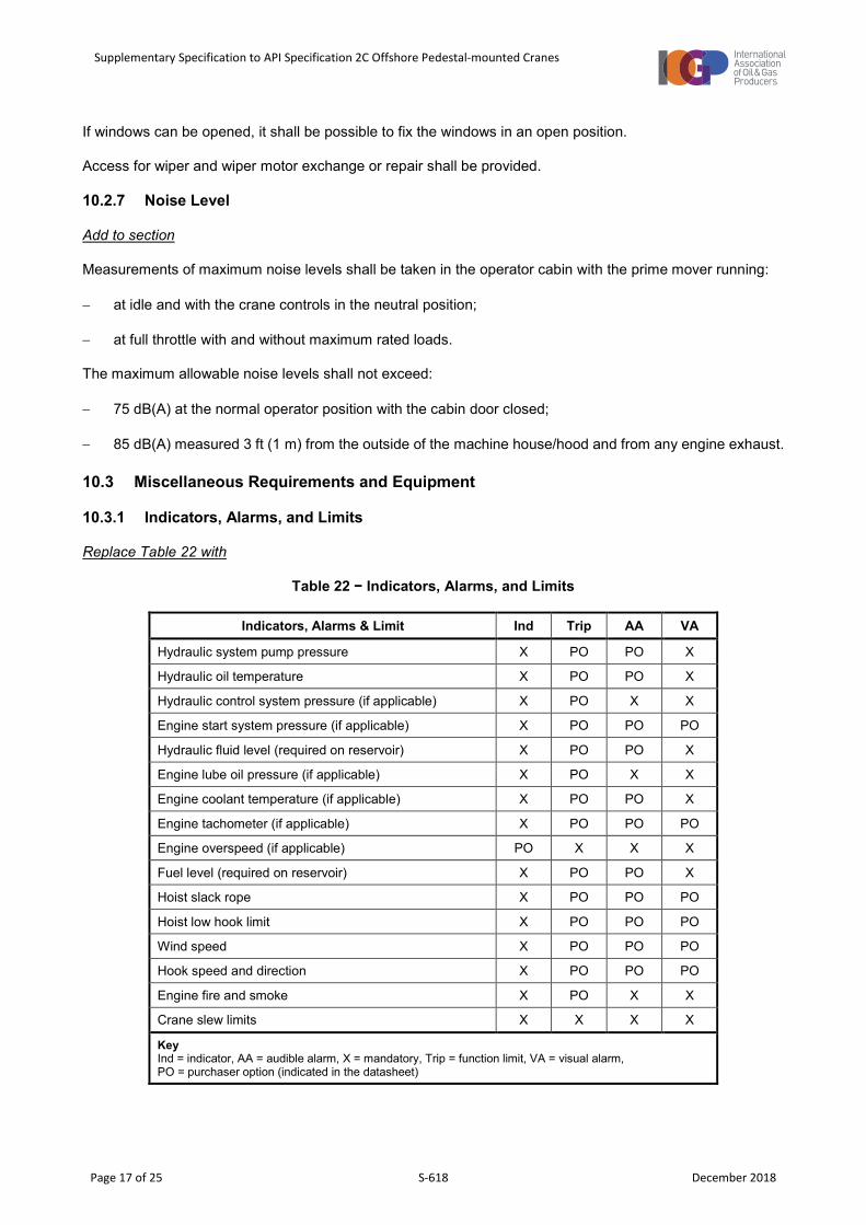
Replace Table 22 with
Table 22 − Indicators, Alarms, and Limits
Indicators, Alarms & Limit Ind Trip AA VA
Hydraulic system pump pressure X PO PO X
Hydraulic oil temperature X PO PO X
Hydraulic control system pressure (if applicable) X PO X X
Engine start system pressure (if applicable) X PO PO PO
Hydraulic fluid level (required on reservoir) X PO PO X
Engine lube oil pressure (if applicable) X PO X X
Engine coolant temperature (if applicable) X PO PO X
Engine tachometer (if applicable) X PO PO PO
Engine overspeed (if applicable) PO X X X
Fuel level (required on reservoir) X PO PO X
Hoist slack rope X PO PO PO
Hoist low hook limit X PO PO PO
Wind speed X PO PO PO
Hook speed and direction X PO PO PO
Engine fire and smoke X PO X X
Crane slew limits X X X X
Key Ind = indicator, AA = audible alarm, X = mandatory, Trip = function limit, VA = visual alarm, PO = purchaser option (indicated in the datasheet)
Supplementary Specification to API Specification 2C Offshore Pedestal-mounted Cranes
Page 18 of 25 S-618 December 2018
Add to section
All motions (hoist, luff and slew) which have limits shall have both a speed reduction limit and a working limit.
The speed reduction limit shall activate before the working limit, to reduce the speed before activation of this limit and avoid sudden motion stop and shock loading.
On rope luffing cranes, the luffing system shall be fitted with an independent boom upper ultimate limit which stops all luff up motion in the event of the luff upper limit failing.
The motion limiters (load hoist and luffing hoist) shall only be capable of being manually or automatically overridden for maintenance, stowage or safety reasons (AOPS, MOPS). Any override of motion limiters shall provide a permanent visual and temporary audible warning.
Manual override of the motion limiters shall either be by a “hold-to-run” device or by the use of special tools.
10.3.2 Boom Equipment
10.3.2.1 Boom Angle Limiters and Shut-Off Devices
Replace second sentence with
A low-angle limiter shall also be provided for cranes fitted with boom winches.
10.3.2.4 Boom and Load Indicators
Replace item c) and Table 23 with
c) a load-moment indicator system (LMIS) shall be provided.
NOTE The LMIS provides the crane operator an indication of hook load, load radius and SWL (rated capacity). The system has audible and visual alarms. The LMIS shall be programmed with all crane ratings (onboard, offboard and personnel) for all hooks.
Add to section
The LMIS shall act on all hooks, boom configurations and wire rope reeving configurations.
The LMIS shall include a continuous visual display of the following:
− selected wave height (for offboard lifts);
− actual hook load;
− load radius; and
− rated capacity at the radius for platform lifts, or for the selected wave height for offboard lifts.
The accuracy of displayed values shall be within +/- 2.5 % of full scale reading.
The LMIS shall emit:
− a continuous audible and visual warning when the actual hook load exceeds 90 % of the rated capacity for any lift conditions. The operator’s acknowledgement of the alarm shall silence the audible warning; and
Supplementary Specification to API Specification 2C Offshore Pedestal-mounted Cranes
Page 19 of 25 S-618 December 2018
− a continuous audible and visual warning inside and outside the cabin when the actual hook load exceeds 110 % of the rated capacity for any lift conditions (in accordance with the correspondent significant wave height). In this condition, the crane shall not be able to lower the boom or raise the load.
A rated capacity limiter shall prevent exceedance of the rated capacity, by automatically stopping the hoist up, telescope out, luff out and applicable folding motions. Reverse motions, which will reduce the overload or over-moment, shall not be prevented.
Add new section
10.3.2.5 Data Recorder
A data recorder with the following features shall be installed:
− records crane motions, loads and lifetime load cycle history;
− enables the key operational parameters of the crane to be reviewed.
As a minimum, the system shall record the following information when the crane is operating:
− date (dd/mm/yyyy);
− time (hh/mm/ss);
− duration (s);
− rated load at hook position for all hoists;
− actual load at hook position for all hoists;
− boom radius and angle;
− peak dynamic load at hook position for all hoists;
− load chart;
− alarm activation;
− any overrides or bypass activated or alarms acknowledged; and
− crane operator unique identification (if selected in datasheet).
The system shall be automatic and not require any manual activation. It shall not be possible to deactivate the data recorder.
The memory shall be of sufficient capacity to record and store all data, without requiring download or external backup, for a minimum of 180 calendar days.
The memory shall be able to be downloaded via standard means.
The output data file should be in a comma-separated values (CSV) format or equivalent common user format.
If any proprietary software or hardware is required, it shall be supplied with the crane. Any passwords that are required to access the system shall be provided in the installation, operation and maintenance manual.
Supplementary Specification to API Specification 2C Offshore Pedestal-mounted Cranes
Page 20 of 25 S-618 December 2018
10.3.5 Hydraulic and Pneumatic Line Protection
Add to section
The hydraulic system shall comply with ISO 4413.
The hydraulic oil grade and cleanliness shall be specified by the crane manufacturer, for all operating conditions, including FAT, SAT and operating location.
All hydraulic components shall be suitable for an offshore environment, including resistance to corrosion. Flanges, split flanges and hose ends which are not AISI 316L material shall be chromated and protected with grease band (petroleum impregnated tape or equivalent).
The hydraulic oil tank shall have means for complete drainage and cleaning. It shall be equipped with a breathing filter, located and designed to prevent potential vapor hazard to personnel.
Hose ends shall allow the fitting of plugs or caps for maintenance.
Hydraulic hoses shall be pressure tested to 1.5 times the maximum working pressure.
All hydraulic lines shall have permanent identification, traceable to the hydraulic schematic, hose register and certificates.
Suction lines, from the tank to the pumps, shall have isolation valves to accommodate pump and hose replacement without the need for draining the oil tank. Isolation valves shall be secured in open positions and be permanently and clearly labelled.
The oil tank shall contain a local visual oil level indicator and separate low and low-low oil level detectors. The low-low level detection point must be set clearly below the low-level detection point.
Upon detection of a low oil level, there shall be audible and visual alarms within the operator cabin.
Upon detection of a low-low oil level, there shall be audible and visual alarms within the operator cabin, separate to the low oil level alarms. The crane shall be automatically shut down if the low level and separate low-low level alarms have both activated.
The hydraulic system shall include allowance for an additional circulation system for continuous flushing, filtration and removal of water from the hydraulic oil. This system shall comprise of a separate circulation pump and necessary filters. The circulation system shall be provided if selected in the datasheet. Accumulators shall be equipped with a pressure gauge and permanent means for draining to verify the pre-charge pressure. Necessary fittings for refilling shall be installed.
Test points shall be provided on the main pressure lines, return lines and on any pilot and boost lines in the hydraulic system. All test points shall be clearly labelled.
The hydraulic system and surroundings shall be designed for spillage containment.
Before handover at SAT, the cleanliness of the hydraulic system shall be tested and certification provided.
10.3.6 Anti Two-block
Add to section
Structural damage to the crane or crane boom due to hook or hook block impact shall be prevented while any hooks are in their stowed position.
Hook block impact shall not lead to possible dropped objects.
Supplementary Specification to API Specification 2C Offshore Pedestal-mounted Cranes
Page 21 of 25 S-618 December 2018
For cranes with multi-hook configuration, a method to restrain the inactive hook blocks while the active block is in use, shall be provided to avoid damage to itself, the boom or other hoist ropes.
10.3.7 Emergency Load Lowering
Add to section
Emergency lowering functions shall be independent of the main crane systems. Manual lowering of loads and release of slew brakes shall remain possible in the event of loss, or unavailability, of the crane’s main control system.
10.3.8 Miscellaneous Equipment
Add new section
10.3.8.6 Dropped Objects
The manufacturer shall perform an assessment of the crane to mitigate all potential dropped object hazards by appropriate:
− removal of any unnecessary items;
− design of the item’s primary securing method;
− use of secondary retention.
NOTE An example of secondary retention is a lock nut or shackle pin secured in a shackle bow using a threaded nut locked by a split pin. Another example is a wire strap or a chain fixed between crane structure and the object, which is capable of catching and holding objects whose primary securing method has failed.
Add new section
10.3.8.7 Maintenance Access
Access shall be provided to all crane components which require routine inspection and maintenance, without the need for special scaffolding, rope access or similar special equipment. This shall be provided on the crane itself, unless suitable access to all required components is provided by other permanent means from the facility on which the crane is installed.
This includes the provision of all ladders, walkways and platforms necessary to access components, such as:
− A-frame head sheaves and critical pins, lights, anemometers, boom buffers, etc.;
− boom connectors, sheaves, pins, lights, LMIS components, heel pins;
− winches; and
− exterior cabin components such as windscreen wipers, horns, HVAC units, loud-speakers, etc.
All ladders, walkways and platforms shall include appropriate handrails suitable for normal personnel access.
Ram-luffing, telescoping and knuckle-boom cranes shall be provided with:
− padeyes for luffing cylinder removal; and
− means to service and replace the ram or telescopic boom cylinder.
Supplementary Specification to API Specification 2C Offshore Pedestal-mounted Cranes
Page 22 of 25 S-618 December 2018
Maintenance davits, lifting beams and padeyes shall be provided to enable all major components to be replaced without the need for the use of additional cranes. This includes all components in the machinery house (such as the prime mover, gearbox, cabinets and pumps), winches, sheaves and slew drive components.
All major structural components (including the pedestal adaptor, machinery deck, cabin, machinery house, A-frame and boom sections) shall be provided with suitable lifting points, or other approved means, to enable components to be lifted individually. Procedures and instructions for their use shall be provided in the installation, operation and maintenance manual.
The maintenance instructions shall include detailed lifting procedures for the lifting of each major structural component (including the pedestal adaptor, machinery deck, cabin, machinery house, luffing cylinders, knuckle cylinders, telescoping cylinders, A-frame and boom sections). The procedures shall include drawings with clearly marked (and verified) centre of gravity and total weight.
All lifting points, davits, lifting beams and padeyes shall be permanently and legibly marked with a unique identification number and the SWL, and identified within the installation, operation and maintenance manual lifting procedures.
The boom design shall incorporate permanent access to the connector fasteners on the top, bottom and both sides of the boom.
Permanent access to the boom hoist dead end connection shall be provided.
All grease nipples shall be easily accessible, with the crane boom stowed in the boom rest, from permanently installed walkways and platforms.
Add new section
10.3.8.8 Aviation Warning Lights
The crane shall be fitted with permanent aircraft warning lights according to statutory civil aviation regulations.
Add new section
10.3.8.9 Communication
Communication equipment shall be provided to enable the crane operator to communicate with the platform and the supply vessels and other units involved in the lifting operations.
The crane operator shall be able to operate the radio communication system by a microphone speaker system or microphone headset system, without moving their hands from the main control levers.
The crane communication system shall incorporate a public-address system.
Add new section
10.3.9 Boom Tip Camera
If a boom tip camera is required, it shall be specified by the purchaser in the datasheet, either as the manufacturer’s standard system, or to be supplied in accordance with this specification.
A camera system specified in accordance with this specification shall meet the following requirements:
a) A boom tip camera and a 10 in (254 mm) colour monitor to be located in the operator cabin shall be provided.
Supplementary Specification to API Specification 2C Offshore Pedestal-mounted Cranes
Page 23 of 25 S-618 December 2018
b) The camera shall be mounted in explosion-proof housing with damping and designed for a marine environment.
c) Remote controls for camera zoom, focus and iris shall be mounted in a location that can be easily reached and operated by the seated operator.
Add new section
10.4 Lighting
The following lighting shall be provided:
− All enclosed areas for operation and maintenance, such as the cabin and the machinery house, shall have lighting to ensure safe operation and maintenance.
− Access to operator positions and areas where maintenance is to be performed shall have adequate lighting.
− The emergency escape and access routes from operator positions shall be equipped with emergency lighting.
− The boom shall have floodlights installed for illumination of the load, for all operating positions, without relying on other facility lighting.
11 Manufacturing Requirements
11.1 Material Requirements of Critical Components
Add new section
11.1.9 Surface Protection
All exposed surfaces and components shall be protected by a surface protection system based on material type and minimum and maximum operating temperatures and the specified crane operational life.
Add new section
11.5 Interchangeability
Equipment and components including valves, filters, fittings, bearings, and seals in equivalent service shall be interchangeable as far as practicable, for the purpose of minimizing spare parts.
12 Design Validation by Testing
12.3 Operational Tests
Add to section
Cranes shall undergo initial factory acceptance testing before delivery to site. This shall be on a fully assembled crane or functional sub-assemblies, as selected by the purchaser in the datasheet.
The manufacturer shall include the proposed FAT and SAT procedures for all cranes in their proposal documentation. These procedures shall be derived from IOGP S-618Q, Annex C and Annex D.
All cranes shall undergo fully assembled site acceptance testing.
Supplementary Specification to API Specification 2C Offshore Pedestal-mounted Cranes
Page 24 of 25 S-618 December 2018
Replace section heading
13 Marking and Labelling
Add new section
13.1 Component Traceability
All components shall be traceable to the OEM information. If the crane manufacturer adds identification details, this shall not interfere with or detract from any OEM information.
All OEM parts information shall be readily identifiable in crane documentation, including drawings and spare parts records, and not replaced by crane manufacturer information.
Add new section
13.2 Component Identification System
The component identification system (sometimes referred to as tag numbering) is used to identify components or sub-assemblies on the crane. This is used for multiple purposes including the management of spare parts and maintenance.
The crane assembly shall be assigned a single end-user tag number, identified in the datasheet.
Manufacturers are required to identify all components in the installation, operation and maintenance manual, for spare parts procurement and troubleshooting purposes.
Following is a description of the requirements for each of the options, selected in the datasheet.
Option 1: Manufacturer system
The standard component identification system used by the manufacturer, without any purchaser modifications.
Option 2: Integrated manufacturer - purchaser system
The standard component identification system used by the manufacturer, with only the listed component and sub-assemblies identified using the purchaser system.
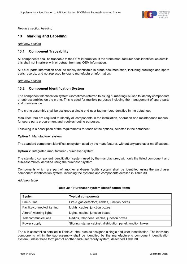
Components which are part of another end-user facility system shall be identified using the purchaser component identification system, including the systems and components detailed in Table 30.
Add new table
Table 30 − Purchaser system identification items
System Typical components
Fire & Gas Fire & gas detectors, cables, junction boxes
Facility-connected lighting Lights, cables, junction boxes Aircraft warning lights Lights, cables, junction boxes
Telecommunications Radios, telephone, cables, junction boxes
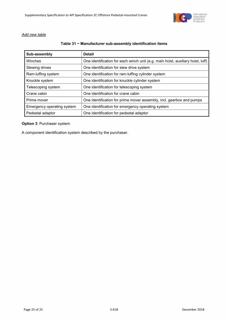
Power supply Slipring, starter cabinet, distribution panel, junction boxes The sub-assemblies detailed in Table 31 shall also be assigned a single end-user identification. The individual components within the sub-assembly shall be identified by the manufacturer’s component identification system, unless these form part of another end-user facility system, described Table 30.
Supplementary Specification to API Specification 2C Offshore Pedestal-mounted Cranes
Page 25 of 25 S-618 December 2018
Add new table
Table 31 − Manufacturer sub-assembly identification items
Sub-assembly Detail
Winches One identification for each winch unit (e.g. main hoist, auxiliary hoist, luff)
Slewing drives One identification for slew drive system Ram-luffing system One identification for ram-luffing cylinder system
Knuckle system One identification for knuckle cylinder system
Telescoping system One identification for telescoping system Crane cabin One identification for crane cabin
Prime mover One identification for prime mover assembly, incl. gearbox and pumps
Emergency operating system One identification for emergency operating system Pedestal adaptor One identification for pedestal adaptor
Option 3: Purchaser system
A component identification system described by the purchaser.
This specification supplements API Specification 2C Offshore Pedestal-mounted Cranes, 7th Edition (2012), referring sequentially to the same clause numbers.