specification technical requirements for metering mv … · specification – technical...
TRANSCRIPT
Specification – Technical Requirements for Metering MV CT-VT Units
Standard Number: HPC-8DJ-16-0002-2013
DM# 3736817 Page 2 of 40 Print Date 10/10/2013
© Horizon Power Corporation – Document Number: HPC-8DJ-16-0002-2013
Uncontrolled document when printed. Printed copy expires one week from print date. Refer to Document No. for current version.
Document Control
Author Name: Paul Savig
Position: Engineer Manager Standards
Document Owner
(May also be the Process Owner)
Name: Justin Murphy
Position: Manager Asset & Works
Approved By * Name: Justin Murphy
Position: Manager Asset & Works
Date Created/Last Updated August 2013
Review Frequency ** 5 yearly
Next Review Date ** August 2018
* Shall be the Process Owner and is the person assigned authority and responsibility for managing the whole process, end-to-end, which may extend across more than one division and/or functions, in order to deliver agreed business results.
** Frequency period is dependent upon circumstances– maximum is 5 years from last issue, review, or revision whichever is the latest. If left blank, the default shall be 1 year unless otherwise specified.
Revision Control
Revision Date Description
0 27/09/2013 Initial Document Creation
STAKEHOLDERS The following positions shall be consulted if an update or review is required:
Manager Engineering Services
Manager Engineering Systems Planning
Manager Assets and Works
DM# 3736817 Page 3 of 40 Print Date 10/10/2013
© Horizon Power Corporation – Document Number: HPC-8DJ-16-0002-2013
Uncontrolled document when printed. Printed copy expires one week from print date. Refer to Document No. for current version.
TABLE OF CONTENTS
1 SCOPE ......................................................................................................... 5
2 NORMATIVE REFERENCES ....................................................................... 5
2.1 Standards ............................................................................................................... 5
2.2 Definitions and Abbreviations ................................................................................. 6
2.2.1 Definitions .......................................................................................................................... 6
2.2.2 Abbreviations ..................................................................................................................... 6
2.3 Drawings ................................................................................................................ 6
3 REQUIREMENTS ......................................................................................... 7
3.1 Power System Particulars ....................................................................................... 7
3.1.1 Rated Voltages .................................................................................................................. 7
3.1.2 Fault Rating ....................................................................................................................... 7
3.1.3 Nominal System Frequency ............................................................................................... 7
3.1.4 System Insulation Levels ................................................................................................... 7
3.2 Service Conditions .................................................................................................. 7
3.2.1 Environmental Conditions .................................................................................................. 7
3.2.2 Service Requirements ........................................................................................................ 8
3.2.3 Safety ................................................................................................................................ 8
4 CT-VT UNIT DESIGN AND CONSTRUCTION ............................................. 9
4.1 General .................................................................................................................. 9
4.2 Tank ....................................................................................................................... 9
4.3 Bushings ................................................................................................................ 9
4.4 Joints and Gaskets ................................................................................................. 9
4.5 Insulating Medium ................................................................................................ 10
4.6 Housing and Corrosion Protection ........................................................................ 10
4.6.1 Aerial CT-VT Units ........................................................................................................... 10
4.6.2 Ground-mounted CT-VT Units.......................................................................................... 10
4.7 CT-VT Unit Fittings ............................................................................................... 10
4.7.1 Lifting Lugs/Eyes ............................................................................................................. 10
4.7.2 Rating Plates ................................................................................................................... 10
4.7.3 Terminal Markings ........................................................................................................... 11
4.7.4 Earthing Bracket .............................................................................................................. 11
4.7.5 External Markings ............................................................................................................ 12
4.8 Electrical Requirements ........................................................................................ 12
4.8.1 General............................................................................................................................ 12
4.8.2 Tap Switch (where specified) ........................................................................................... 12
4.8.3 Earthing ........................................................................................................................... 13
4.8.4 Internal CT & VT Core and Primaries ............................................................................... 13
DM# 3736817 Page 4 of 40 Print Date 10/10/2013
© Horizon Power Corporation – Document Number: HPC-8DJ-16-0002-2013
Uncontrolled document when printed. Printed copy expires one week from print date. Refer to Document No. for current version.
4.8.4.1 Current Transformer ...................................................................................................................... 13
4.8.4.2 Voltage Transformer ...................................................................................................................... 14
5 AERIAL CT-VT UNIT REQUIREMENTS .................................................... 15
5.1 General ................................................................................................................ 15
5.2 Lifting Lugs/Eyes .................................................................................................. 15
5.3 CT-VT Mounting Brackets .................................................................................... 15
5.4 Surge Arrestor Brackets ....................................................................................... 15
5.5 Bushings .............................................................................................................. 15
5.6 Secondary Cable .................................................................................................. 16
5.7 Terminal Box ........................................................................................................ 16
6 GROUND MOUNTED CT-VT UNIT REQUIREMENTS .............................. 17
6.1 General ................................................................................................................ 17
6.2 Lifting Lugs/Eyes .................................................................................................. 17
6.3 MV/LV Cubicle ...................................................................................................... 17
6.4 Secondary Wiring ................................................................................................. 18
7 STORAGE .................................................................................................. 19
8 RELIABILITY .............................................................................................. 19
9 SAFETY ...................................................................................................... 19
10 ENVIRONMENTAL CONSIDERATIONS ................................................... 19
11 TESTS ........................................................................................................ 19
11.1 Test Requirements ............................................................................................... 19
11.1.1 Type Tests ....................................................................................................................... 19
11.1.2 Routine Tests .................................................................................................................. 20
12 DOCUMENTATION AND SAMPLES ......................................................... 20
12.1 Type Test Certificates/Reports ............................................................................. 20
12.2 Samples ............................................................................................................... 20
12.2.1 Test Samples ................................................................................................................... 20
APPENDIX A – REVISION INFORMATION ..................................................................................................... 21
APPENDIX B – QUALITY ASSURANCE (TO BE COMPLETED BY STORES) ................................................. 22
APPENDIX C – SCHEDULES A & B: ENQUIRY DOCUMENT ......................................................................... 25
APPENDIX D – SCHEDULE C: COMPLIANCE DOCUMENT ........................................................................... 29
APPENDIX E – SCHEDULE D: DEPARTURES FROM TECHNICAL SPECIFICATION..................................... 32
APPENDIX F – CT-VT UNIT DESCRIPTION ................................................................................................... 33
APPENDIX G – SPECIFICATION DRAWINGS ................................................................................................ 35
DM# 3736817 Page 5 of 40 Print Date 10/10/2013
© Horizon Power Corporation – Document Number: HPC-8DJ-16-0002-2013
Uncontrolled document when printed. Printed copy expires one week from print date. Refer to Document No. for current version.
1 SCOPE
This specification covers Horizon Power's requirements for the manufacture, testing and supply of medium-voltage overhead and ground mounted energy metering CT-VT units used on AC systems up to and including 33 kV.
Tests prescribed will evaluate the performance of these CT-VT units and shall comply with this specification.
Approval in terms of this specification shall be obtained by one or a combination of the following:
a) successful completion of the appropriate tests required by this specification by an independent and accredited test authority.
b) provision of test certificates from an independent and accredited test authority based upon an alternative specification, with test requirements at least equivalent to this specification.
NOTE: Verification of accreditation of the test authority shall be provided by
NATA (National Association of Testing Authorities) accredited test house or by a test house possessing accreditation from a NATA MRA (Mutual Recognition Agreement) partner.
2 NORMATIVE REFERENCES
2.1 Standards
The following documents contain provisions that, through reference in the text, constitute requirements of this specification. At the time of publication, the editions indicated were valid. Information on currently valid national and international standards and specifications can be obtained from SAI Global – Standards On-Line data base or equivalent standards database.
Table 1: List of Applicable Standards
STANDARD DESCRIPTION
AS 1243 Voltage Transformers for Measurement and Protection
AS 1767.1 Insulating Oil for Transformers and Switchgear
AS 1931 Parts 1 & 2
High Voltage Testing Techniques - General Definitions and Test Requirements
AS 2312 Guide to the Protection of Iron and Steel against Exterior Atmospheric Corrosion
AS 2700 Colour Standards for General Purposes
AS/NZS 3000 Electrical Installations (known as Australian/New Zealand Wiring Rules)
AS 4436 Guide for Selection of Insulators in respect of Polluted Conditions
AS 60044-3 Instrument Transformers - Combined Transformers
AS 60137 Insulated Bushings for Alternating Voltages above 1000 V
DM# 3736817 Page 6 of 40 Print Date 10/10/2013
© Horizon Power Corporation – Document Number: HPC-8DJ-16-0002-2013
Uncontrolled document when printed. Printed copy expires one week from print date. Refer to Document No. for current version.
STANDARD DESCRIPTION
AS 60529 Degrees of Protection provided by Enclosures for Electrical Equipment
Other applicable documents:
WA Electricity Industry Metering Code 2012
2.2 Definitions and Abbreviations
For the purposes of this specification the following definitions apply:
2.2.1 Definitions
1) Aerial: The method of MV and LV termination of the equipment to an overhead distribution system.
2) Air-filled enclosure: A metallic enclosure designed to protect the ends of
the cables and bushings, providing a weatherproof enclosure with a minimum rating of IP54.
3) Equipment: means all equipment, accessories and terminations necessary to form a complete CT-VT in relation to this specification.
2.2.2 Abbreviations
1) AC: Alternating Current
2) AMF: Approved Manufacturing Facility
3) AS: Australian Standard
4) CT-VT: Current Transformer Voltage Transformer
5) LV: Low Voltage < 1000 volts ac
6) MV: Medium Voltage >1000 volts ac; <35 000 volts ac
2.3 Drawings
The drawings listed below forms part of this specification, see Appendix G:
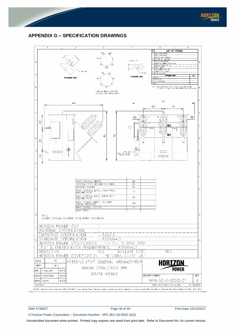
1) HPA-SD-E-00030-01 (Aerial Connection 3 phase)
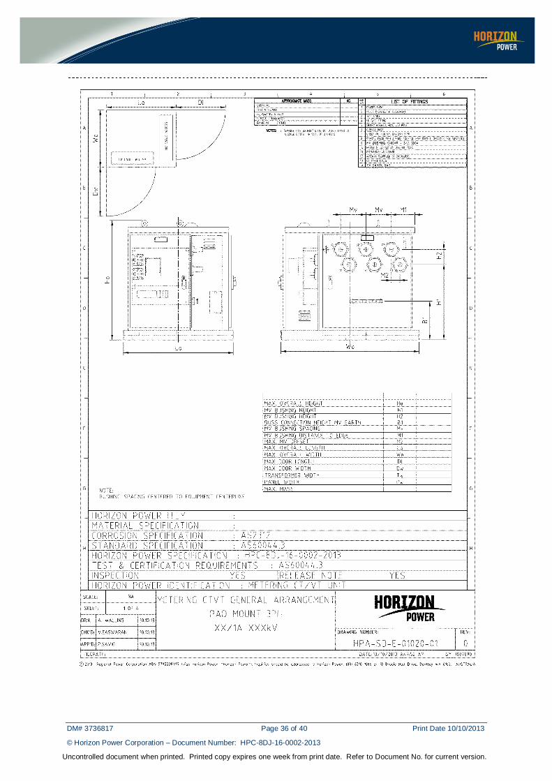
2) HPA-SD-E-01020-01 (Pad-Mount 3 phase)
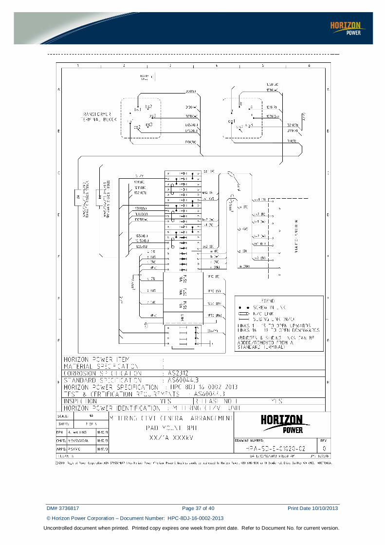
3) HPA-SD-E-01020-02 (Pad-Mount 3 phase internals
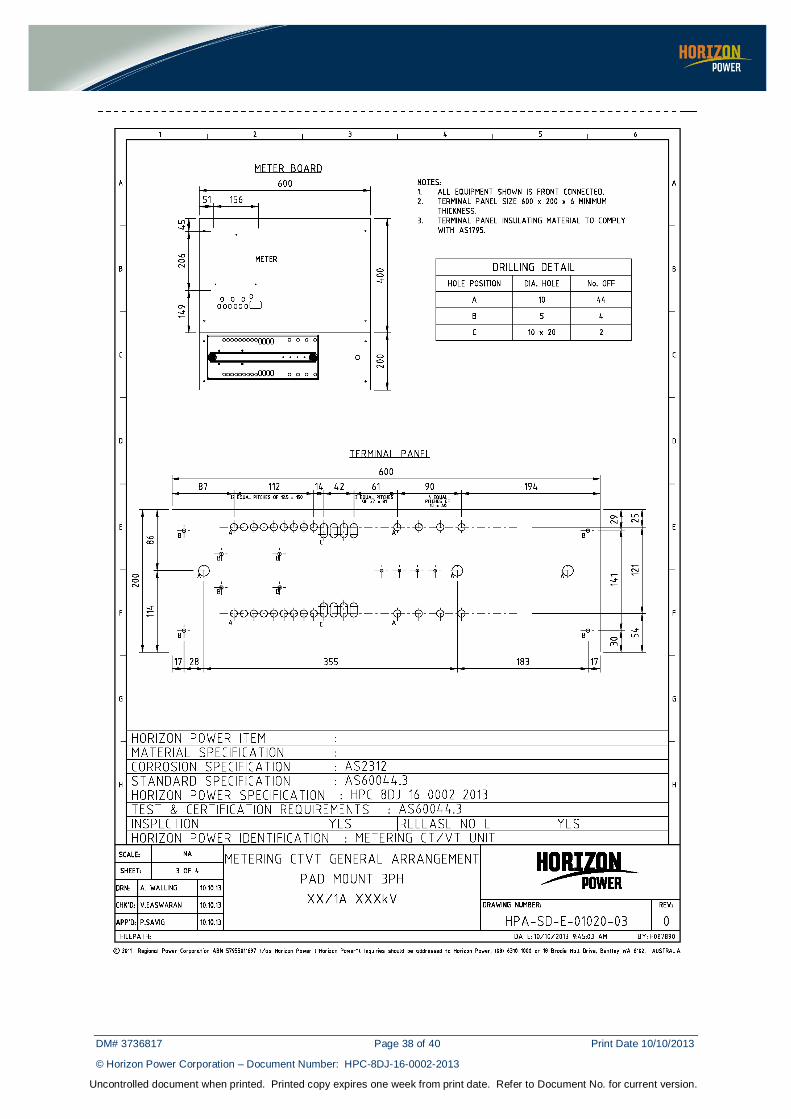
4) HPA-SD-E-01020-03 (Pad-Mount 3 phase wiring)
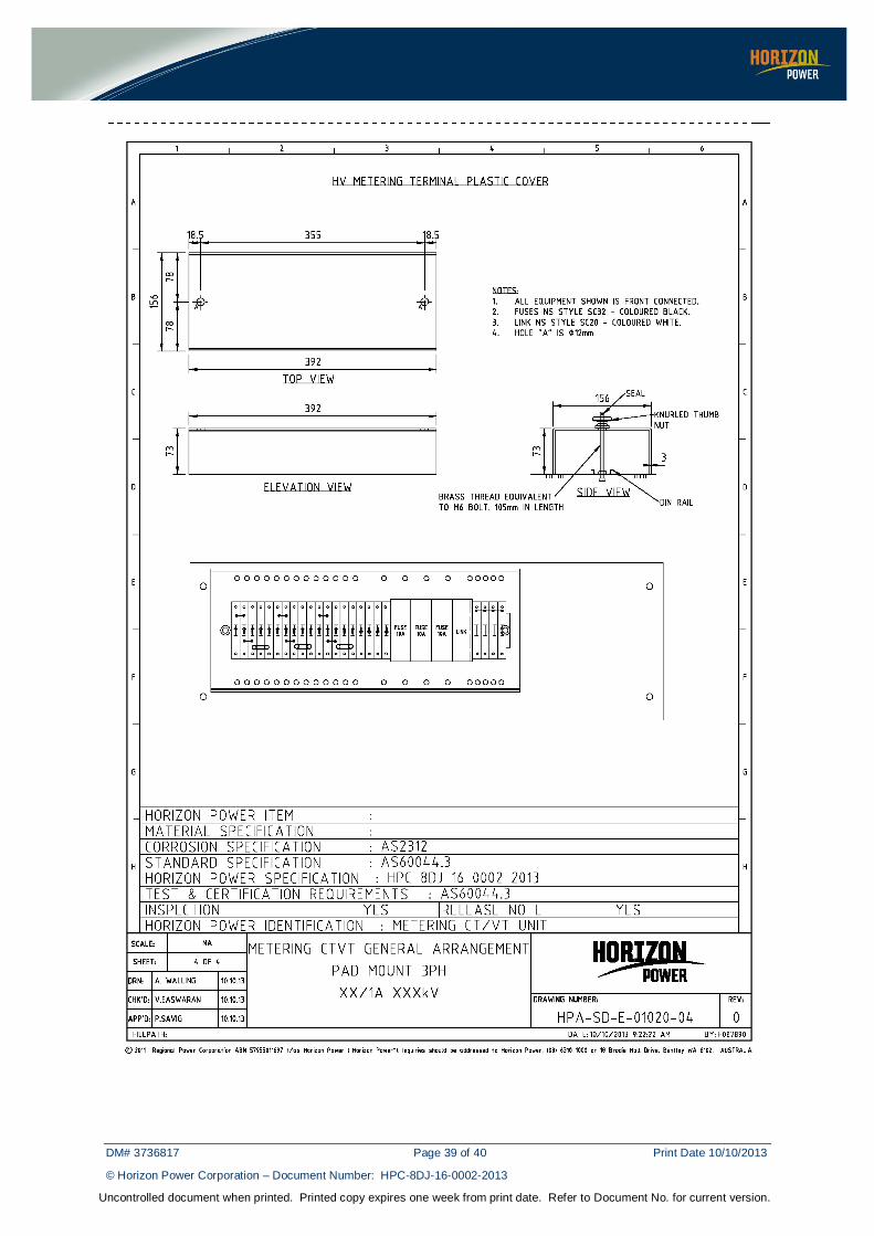
5) HPA-SD-E-01020-04 (Pad-Mount termination board)
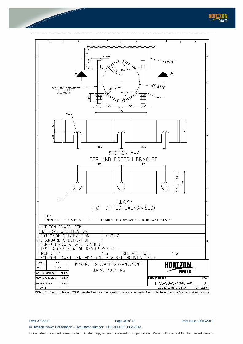
6) HPA-SD-S-00001-01 (Bracket and Clamp for Aerial Mounting)
DM# 3736817 Page 7 of 40 Print Date 10/10/2013
© Horizon Power Corporation – Document Number: HPC-8DJ-16-0002-2013
Uncontrolled document when printed. Printed copy expires one week from print date. Refer to Document No. for current version.
3 REQUIREMENTS
3.1 Power System Particulars
3.1.1 Rated Voltages
The rated voltages considered in this specification shall be:
1) 6.6-11 kV (three phase)
2) 22 kV(three phase)
3) 33 kV(three phase)
3.1.2 Fault Rating
The Maximum design fault currents are as follows:
1) 13.1 kA rms / 1 second for 33 kV and 22 kV systems
2) 18.1 kA rms / 1 second for 11 kV and 6.6 kV systems
Equipment that is rated for operation in conditions with a three (3) second fault duration will be considered favourably.
3.1.3 Nominal System Frequency
The nominal system frequency is 50 Hz.
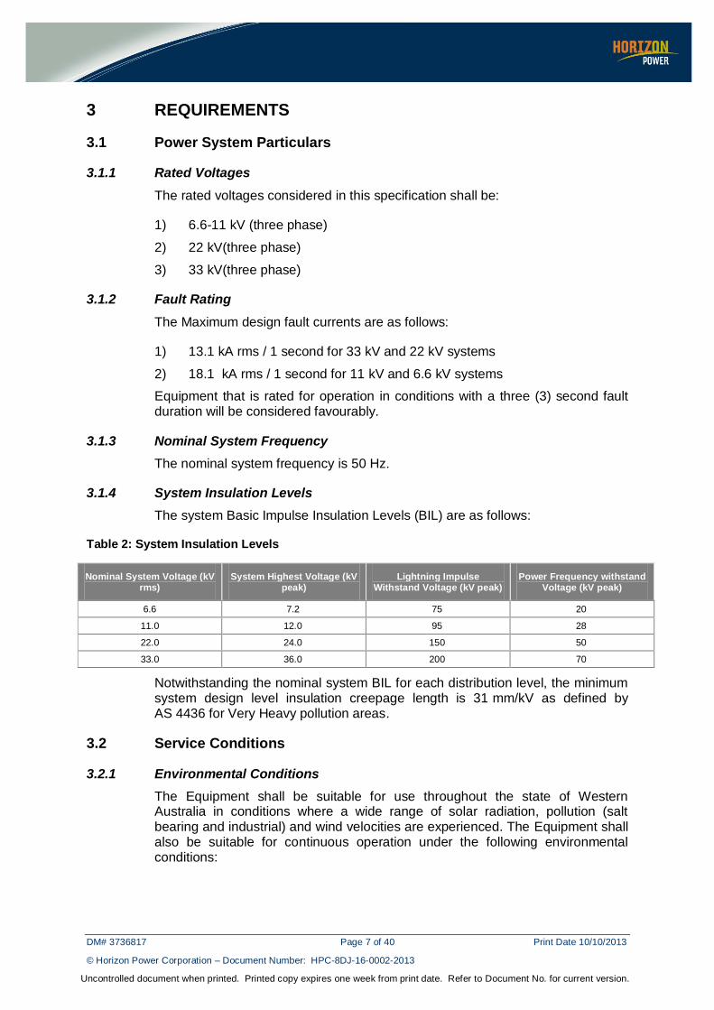
3.1.4 System Insulation Levels
The system Basic Impulse Insulation Levels (BIL) are as follows:
Table 2: System Insulation Levels
Nominal System Voltage (kV rms)
System Highest Voltage (kV peak)
Lightning Impulse Withstand Voltage (kV peak)
Power Frequency withstand Voltage (kV peak)
6.6 7.2 75 20
11.0 12.0 95 28
22.0 24.0 150 50
33.0 36.0 200 70
Notwithstanding the nominal system BIL for each distribution level, the minimum system design level insulation creepage length is 31 mm/kV as defined by AS 4436 for Very Heavy pollution areas.
3.2 Service Conditions
3.2.1 Environmental Conditions
The Equipment shall be suitable for use throughout the state of Western Australia in conditions where a wide range of solar radiation, pollution (salt bearing and industrial) and wind velocities are experienced. The Equipment shall also be suitable for continuous operation under the following environmental conditions:
DM# 3736817 Page 8 of 40 Print Date 10/10/2013
© Horizon Power Corporation – Document Number: HPC-8DJ-16-0002-2013
Uncontrolled document when printed. Printed copy expires one week from print date. Refer to Document No. for current version.
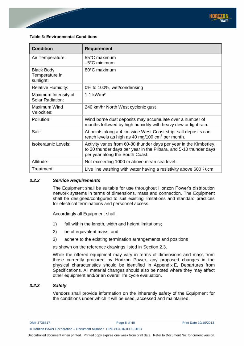
Table 3: Environmental Conditions
Condition Requirement
Air Temperature: 55°C maximum –5°C minimum
Black Body Temperature in
sunlight:
80°C maximum
Relative Humidity: 0% to 100%, wet/condensing
Maximum Intensity of Solar Radiation:
1.1 kW/m²
Maximum Wind Velocities:
240 km/hr North West cyclonic gust
Pollution: Wind borne dust deposits may accumulate over a number of months followed by high humidity with heavy dew or light rain.
Salt: At points along a 4 km wide West Coast strip, salt deposits can reach levels as high as 40 mg/100 cm2 per month.
Isokeraunic Levels: Activity varies from 60-80 thunder days per year in the Kimberley, to 30 thunder days per year in the Pilbara, and 5-10 thunder days
per year along the South Coast.
Altitude: Not exceeding 1000 m above mean sea level.
Treatment: Live line washing with water having a resistivity above 600 .cm
3.2.2 Service Requirements
The Equipment shall be suitable for use throughout Horizon Power’s distribution network systems in terms of dimensions, mass and connection. The Equipment shall be designed/configured to suit existing limitations and standard practices for electrical terminations and personnel access.
Accordingly all Equipment shall:
1) fall within the length, width and height limitations;
2) be of equivalent mass; and
3) adhere to the existing termination arrangements and positions
as shown on the reference drawings listed in Section 2.3.
While the offered equipment may vary in terms of dimensions and mass from those currently procured by Horizon Power, any proposed changes in the physical characteristics should be identified in Appendix E, Departures from Specifications. All material changes should also be noted where they may affect other equipment and/or an overall life cycle evaluation.
3.2.3 Safety
Vendors shall provide information on the inherently safety of the Equipment for the conditions under which it will be used, accessed and maintained.
DM# 3736817 Page 9 of 40 Print Date 10/10/2013
© Horizon Power Corporation – Document Number: HPC-8DJ-16-0002-2013
Uncontrolled document when printed. Printed copy expires one week from print date. Refer to Document No. for current version.
4 CT-VT UNIT DESIGN AND CONSTRUCTION
4.1 General
CT-VT Units shall be adequately braced to withstand all mechanical shocks which may occur under working conditions including those produced by short circuits and also stress resulting from transport, lifting by slings and forces arising from the connection of cables and overhead conductors.
All sharp points on the CT-VT unit’s exterior surfaces will be removed to prevent injury. All fixings shall conform to Australian metric standards and shall be galvanised mild steel unless otherwise specified. Compatible materials shall be used for all fixings to prevent corrosion.
Reference drawings of CTVT Units are listed in Section 2.3.
4.2 Tank
The internal tank of the CT-VT unit and all parts shall be designed to eliminate air pockets whilst the outside surfaces shall be designed to prevent the accumulation of water.
The tank shall be filled with an oil insulating medium and be oil tight.
External surface welding of horizontal and vertical joints shall be on both sides of the joint and in all cases shall be continuous.
All metal work will be electrically bonded to the tank to permit earthing by the Purchaser. If a part cannot be adequately bonded it will be constructed from a suitable insulating material instead of metal.
4.3 Bushings
Bushings shall be in compliance with AS 60137, except where “Non-Load break” type terminals have been specified. The particular requirements for bushings/terminations are detailed in Section 5.5.
Bushings shall be capable of operating under high levels of salt, dust and industrial pollution as detailed in Table 3 and shall comply with Section 3.1.4.
The vendor shall provide information on methods taken to prevent the long-term erosion of the MV bushing gasket by leakage currents.
Where medium voltage bushings are supplied with a higher impulse level than the windings of the voltage transformers, arc-gaps should be used to protect the windings and the gap setting should be stated.
4.4 Joints and Gaskets
All bolted joints shall be rendered oil tight by the use of neoprene cork gaskets or other sealing methods. Where tank covers are bolted rather than fully welded, the sealing method must be submitted to Horizon Power for review.
DM# 3736817 Page 10 of 40 Print Date 10/10/2013
© Horizon Power Corporation – Document Number: HPC-8DJ-16-0002-2013
Uncontrolled document when printed. Printed copy expires one week from print date. Refer to Document No. for current version.
4.5 Insulating Medium
Air-insulated CT-VT units shall not be considered, The CT-VT unit shall be supplied filled with oil to AS 1767.1 with a minimum breakdown voltage of 50 kV and a high flash-point (250 degree C minimum).
4.6 Housing and Corrosion Protection
All internal and external surfaces be protected against corrosion. All exposed metal surfaces shall be protected by the application of a painting system at least equivalent to ISO 9223 Category C4-C5 in Table B1 and suitable for severe marine environments as specified in AS 2312.
Colours shall be to AS 2700 or equivalent as detailed below:
4.6.1 Aerial CT-VT Units
The Vendor shall provide two options concerning the protection of the exterior surfaces for the Aerial CT-VT Units:
1) Hot-dip Galvanising of the CT-VT Unit; or
2) Painting of CT-VT Unit with Paint Colours:
a) 11-6.6 kV - N42 Storm Grey;
b) 22 kV - N42 Storm Grey;
c) 33 kV – G33 Lettuce;
4.6.2 Ground-mounted CT-VT Units
The colour of the exterior of the CT-VT Unit shall be Hawthorn Green – CAMTECT AG692. Coatings for all Ground Mounted Transformers shall contain an anti-graffiti additive.
4.7 CT-VT Unit Fittings
CT-VT Units shall be supplied with fittings as detailed below.
4.7.1 Lifting Lugs/Eyes
Two lifting lugs/eyes shall be provided for lifting the CT-VT unit complete with oil.
4.7.2 Rating Plates
Rating plates shall be stainless steel and clearly legible for the life of the CT-VT unit and located as indicated on the appropriate Drawings listed in Section 2.3.
All rating plates shall incorporate a diagram of connections and shall provide details of the voltage and current transformers. The markings on these plates shall comply fully with the requirements of AS 60044 Part 1 Section 10 and Part 2 Section 11.
DM# 3736817 Page 11 of 40 Print Date 10/10/2013
© Horizon Power Corporation – Document Number: HPC-8DJ-16-0002-2013
Uncontrolled document when printed. Printed copy expires one week from print date. Refer to Document No. for current version.
4.7.3 Terminal Markings
1) The medium voltage terminals shall have the following markings punched or otherwise indelibly marked on the terminals. These terminal markings shall be painted on the tank adjacent to the medium voltage bushings in letter sizes not less than 50 mm in height.
Table 4: MV Terminal Markings
Marking Red Phase
White Phase
Blue Phase
Neutral Phase
MV Terminal (Voltage and Current) - Start
A1 B1 C1 N
MV Terminal (Current) - Finish A2 B2 C2
2) The low voltage terminals are to be legibly and indelibly marked or engraved.
Table 5: LV Terminal Markings
Marking Red
Phase White Phase
Blue Phase
Neutral Phase
LV Terminal (Voltage) a b c n
LV Terminal (Current) - Start as1 bs1 cs1
LV Terminal (Current) – First Tapping as2 bs2 cs2
LV Terminal (Current) – Second Tapping as3 bs3 cs3
Any further LV current tappings would continue with markings 4, 5, etc.
The terminal markings shall be so applied that at the instant when current through the primary winding is from A1 to A2 the direction of the secondary current through the external circuit providing the burden is from as1 to as2.
NOTE: Where 3 x single-phase electromagnetic VT’s are star-connected the
terminals A1, B1, C1 and a1, b1, c1 form the primary and secondary star points.
4.7.4 Earthing Bracket
A corrosion-resistant bare metal earthing bracket, sized at least 50 x 40 x 5 mm with an M14 hole drilled near the centre of the bracket, shall be provided near the bottom of the tank, as close as practicable vertically below the LV neutral terminal.
DM# 3736817 Page 12 of 40 Print Date 10/10/2013
© Horizon Power Corporation – Document Number: HPC-8DJ-16-0002-2013
Uncontrolled document when printed. Printed copy expires one week from print date. Refer to Document No. for current version.
The bracket shall be fitted with an M12 x 40 mm Grade 316 Stainless Steel bolt, nut, locknut and two flat washers. The earth bracket shall be fully welded along one of the 40 x 5 mm sides directly to the tank, i.e. there are to be no bolted connections in the electrical path between the bracket and the tank.
4.7.5 External Markings
In addition to nameplate markings, the Purchaser's identification number shall be stencilled in black numerals onto the tank where it can be easily seen from the ground. Each numeral shall be 75 mm high and have a body width of not less than 12 mm.
DANGER signs as per AS/NZS 3000 shall be fixed to the MV and LV panels of all CT-VT Units which can provide access to high voltage parts. Wording on signs at these locations shall consist of letters not less than 12 mm high and shall contain the words ‘DANGER — HIGH VOLTAGE’.
Picture 1 – 'DANGER HIGH VOLTAGE' sign
4.8 Electrical Requirements
4.8.1 General
The CT-VT units shall have a continuous primary rating of:
1) 400 A for 33 kV & 22 kV; or
2) 630 A for 11 kV & 6.6 kV
and be equipped as detailed in sub-clauses set out below, be wired with ferrules numbered in accordance with the drawings listed in Section 2.3.
Dimensioned outline drawings, schematic circuit, layout and wiring diagrams for shall be submitted for approval by Horizon Power.
4.8.2 Tap Switch (where specified)
Where specified, for dual ratio CT-VT units, the voltage change from nominal to a second primary voltage shall be facilitated by the provision of an externally operated standard 2 position “Off-Circuit” tap-changing switch with a tap position indicator.
The switch mechanism shall be positive in action such that it cannot be maintained midway between full step positions. The operating handle shall be mounted in a position as shown on the appropriate drawing listed in Section 2.3, and shall be capable of being locked in any position.
DM# 3736817 Page 13 of 40 Print Date 10/10/2013
© Horizon Power Corporation – Document Number: HPC-8DJ-16-0002-2013
Uncontrolled document when printed. Printed copy expires one week from print date. Refer to Document No. for current version.
A sealing gland shall be provided on the switch operating shaft where it passes through the tank to prevent “breathing” or “leaking” along the shaft.
4.8.3 Earthing
The metallic sub-frame of the CT-VT units shall be welded to the tank.
The core of the voltage and current transformers shall be effectively bonded to the tank, unless the current transformers are of toroidal form, in which case they shall be effectively insulated.
An earthing terminal or terminals shall be provided within the terminal box of the CT-VT units.
Removable links shall be provided to connect the White phase of the secondary winding of the voltage transformer (terminal b) and the starts (terminals as1, bs1 and cs1), of the Red, White and Blue phases of the secondary windings of the current transformers to the earthing terminal or terminals within the terminal box of the CT-VT unit.
4.8.4 Internal CT & VT Core and Primaries
The Vendor shall provide information as to the quality of steel laminations used in the cores of the current and voltage transformers to maintain the initial accuracy and performance of the CT-VT unit.
The medium voltage windings of the voltage transformers shall be insulated from the tank with the winding ends brought out to MV terminal bushings.
The medium voltage windings of the voltage transformers shall be star connected and brought out to a neutral bushing and connected to the earth terminal with an earth link.
The phase end of the medium voltage winding of the red phase voltage transformer shall be brought out to the same terminal bushing as the start end of the medium voltage winding of the red phase current transformer.
The phase end of the medium voltage winding of the white phase voltage transformer shall be brought out to the same terminal bushing as the start end of the medium voltage winding of the white phase current transformer.
The phase end of the medium voltage winding of the blue phase voltage transformer shall be brought out to the same terminal bushing as the start end of the medium voltage winding of the blue phase current transformer.
4.8.4.1 Current Transformer
1) Secondary Windings
The secondary windings of the current transformers including the tapped connections shall be brought out through oil-tight fittings to terminal bushings which comply with AS 60137.
DM# 3736817 Page 14 of 40 Print Date 10/10/2013
© Horizon Power Corporation – Document Number: HPC-8DJ-16-0002-2013
Uncontrolled document when printed. Printed copy expires one week from print date. Refer to Document No. for current version.
2) Class
In accordance with AS 60044 Part 1 and the Electricity Industry Metering Code, the current transformers shall be Class 0.5 to suit the Type 3 Metering.
3) Rating
The current transformers shall be:
a) 100-200/1 A ratio
b) rated at 15 ohms per phase
c) rated output of 15 VA
d) rated short time current of 25 kA for 1 second
e) have a thermal limit current of not less than 200% of rated current, and
f) have the current ratio change by tapped secondary with all ratios brought out to terminals within the terminal box
4.8.4.2 Voltage Transformer
1) Secondary Windings
The low voltage windings of the voltage transformers shall be star connected inside the tank with the phase ends and neutral brought out through oil-tight fittings to terminal bushings which comply with As 60137. The star point (neutral) shall be insulated from the tank and connected to a separate neutral terminal.
2) Class
In accordance with AS 60044 Part 2 and the Electricity Industry Metering Code, the voltage transformers shall be Class 0.5 to suit Type 3 Metering.
3) Rating
The voltage transformers shall be:
a) secondary output of 110/√3 Volts (i.e. 63.5 V per phase)
b) rated at 48 millisiemens per phase;
c) rated output of 200 VA per phase;
d) voltage factor of 1.5; and
e) uniformly insulated.
DM# 3736817 Page 15 of 40 Print Date 10/10/2013
© Horizon Power Corporation – Document Number: HPC-8DJ-16-0002-2013
Uncontrolled document when printed. Printed copy expires one week from print date. Refer to Document No. for current version.
5 AERIAL CT-VT UNIT REQUIREMENTS
5.1 General
The aerial CT-VT units shall be so designed and constructed that it suitable outdoor operation, either pad-mounted or on a cross-arm fitted to a single pole (refer to Section 2.3 for list of applicable drawings), where all similar parts are interchangeable.
5.2 Lifting Lugs/Eyes
In addition to Section 4.7.1, two additional lifting lugs/eyes shall be provided for removing the internal assembly from the tank. The lifting lugs/eyes shall be so positioned that slings used for lifting do not foul insulators, terminals, windings etc.
5.3 CT-VT Mounting Brackets
All pole-mounted CT-VT Units shall be equipped with standard-pole-mounting brackets welded to the rear wall of the CT-VT tank. It shall be possible to pass a body belt between the pole and the CT-VT tank.
The brackets and tank wall shall be of adequate strength to limit distortion to 3%, when mounted in the service position. Both the top and bottom brackets shall be able to carry the total weight of the CT-VT unit separately.
In addition, two clamps and four threaded rods (M20 x 250 mm) shall be supplied. Each threaded rod shall be supplied with two nuts, two flat washers and one spring washer. The clamps, threaded rods, flat washers, spring washers and nuts shall be hot dipped galvanised in accordance with AS 4680.
Configurations and dimensions of relevant drawings are listed in Section 2.3.
5.4 Surge Arrestor Brackets
Brackets shall be attached adjacent to each MV bushing to enable the Purchaser to mount surge arresters. The surge arrester brackets shall be used as the connection point for the arrestor earth. The brackets shall have a corrosion-resistant, bare metal connecting zone which has the capability to conduct fault current through the surge arrester.
The brackets shall be constructed to accommodate the mounting of polymeric surge arresters, fitted with an M12 earthing stud with a minimum exposed stud length of 45 mm. The arresters shall be mounted onto the bracket either directly or via their integral insulating bracket.
Mounting details shall be as shown on the applicable drawings listed in Section 2.3. The mounting bracket shall have a length of 200 mm with the mounting hole located 20 mm from the outer end of the bracket. The mounting arrangements shall be shown in dotted lines on typical general arrangement drawing submitted with the tender.
5.5 Bushings
Refer to Section 4.3.
DM# 3736817 Page 16 of 40 Print Date 10/10/2013
© Horizon Power Corporation – Document Number: HPC-8DJ-16-0002-2013
Uncontrolled document when printed. Printed copy expires one week from print date. Refer to Document No. for current version.
5.6 Secondary Cable
The CT-VT unit shall be fitted with a suitable secondary cable that meets the following criteria:
1) fifteen meter length of 12 core secondary cable to bring all connections to the meter foot panel with spade or crimp lug terminations.
2) cores of the cable will have a minimum conductor size of 4 mm2.
3) each core will be individually numbered to identify the connection within the terminal box of the metering tank.
4) UV stabilised double insulated PVC/PVC insulation.
5) terminated at the metering tank by a suitable weatherproof cable gland.
5.7 Terminal Box
A terminal box rated at IP54 as per AS 60529 shall be provided on a vertical side of the tank which is not intended to be mounted against a pole or which has the medium voltage bushings on it.
The secondary terminals of the voltage and current transformers are to be housed in the terminal box.
The entry hole for the external cable shall be on the lower side of the terminal box and suitable for a 32 mm diameter cable gland.
DM# 3736817 Page 17 of 40 Print Date 10/10/2013
© Horizon Power Corporation – Document Number: HPC-8DJ-16-0002-2013
Uncontrolled document when printed. Printed copy expires one week from print date. Refer to Document No. for current version.
6 GROUND MOUNTED CT-VT UNIT REQUIREMENTS
6.1 General
The termination of cables shall be facilitated by the provision of conically shaped bushings (preferably to DIN 47636 or equivalent), enabling the use of dead-break plug-in and disconnectable (fixed by screws/bolts) elbow or straight connectors. The cable sealing end arrangement on the fused tee-off circuit may also be in the form of a slip-on termination kit within a track-proof fuse encapsulated plug-in connector system.
It is essential that the cable terminating arrangement on all circuits provides for a fully insulated design, with no exposed live parts.
6.2 Lifting Lugs/Eyes
Refer to Section 4.7.1, though the lifting lugs/eyes shall be removable without leaving voids that could capture water.
6.3 MV/LV Cubicle
The cubicles box shall be rated for IP54 as per AS 60529 with a provision for sealing facilities and house the following:
1) MV Compartment:
a) Three Universal Bussing Wells for connection to the incoming line;
b) Three Universal Bussing Wells for connection to the outgoing circuit;
c) Oil Level Gauge; and
d) MV Earth Bar (minimum of 16 holes)
2) LV Compartment
a) CT and VT secondary terminations;
b) Marshalling terminals of a Universal type that will accommodate a wire size up to 6 mm2 and provided with test plug sockets and short-circuit plugs for the CT’s secondary taps;
c) VT fuse arrangement;
d) Eight 6 mm studs with nuts suitably placed to mount the metering mounting board (to be supplied by Horizon Power). The layout of the mounting board shall be as shown in Drawing HPA-SD-E-01020-03 Shown in Appendix G and listed in Section 2.3; and
e) LV Earth Bar.
The LV Cubicle shall be so located that:
a) It is accessible at all times with the unit in operation; and
DM# 3736817 Page 18 of 40 Print Date 10/10/2013
© Horizon Power Corporation – Document Number: HPC-8DJ-16-0002-2013
Uncontrolled document when printed. Printed copy expires one week from print date. Refer to Document No. for current version.
b) It is between 1000 mm and 1500 mm above ground level for easy access to secondary terminals.
The LV Cubicle shall not contain any such ancillary equipment such as wiring and fusing for panel heaters, etc.
6.4 Secondary Wiring
All wiring within the CT-VT unit shall be 4 mm2 of stranding 7/0.85 mm, so laid and restrained as per AS/NZS 3000 Clause 3.9.8.3, that there is no possibility of it coming into contact with any live apparatus.
CT and VT secondary terminations shall be wired out from their respective terminal boxes to the marshalling enclosure, with all CT taps being brought out.
Terminals or intermediate connectors between CT’s/VT’s terminal boxes and marshalling shall not be used.
Insulated crimp type lugs/connectors are NOT TO be used in any of the CT-VT secondary wiring terminations, non-insulated crimp connectors are permissible.
CT terminals as1, bs1 and cs1 shall be earthed, wired up to the LV Earth Bar.
DM# 3736817 Page 19 of 40 Print Date 10/10/2013
© Horizon Power Corporation – Document Number: HPC-8DJ-16-0002-2013
Uncontrolled document when printed. Printed copy expires one week from print date. Refer to Document No. for current version.
7 STORAGE
The Equipment shall be capable of being stored without deterioration within the temperature range of - 10 °C to + 45 °C for at least 24 months.
8 RELIABILITY
Vendors shall provide information on the reliability of the Equipment and the performance of the materials offered over an operational life of 45 years under the specified field of application and conditions of service.
Information provided shall evidence the claimed reliability and performance for the Equipment offered, including information on Failure Mode and Effect Analysis.
9 SAFETY
Material Safety Data Sheets (MSDS) applicable for each different Equipment or chemical ingredient in the Equipment which is considered harmful to personnel or environment in any manner, shall be supplied with the Proposal.
10 ENVIRONMENTAL CONSIDERATIONS
Vendors shall provide information on the environmental soundness of the design and the materials used in the manufacture of the Equipment offered. In particular, information must address such issues as recyclability and disposability at the end of service life as well as disposability of materials supplied.
11 TESTS
11.1 Test Requirements
Prior to delivery, the units shall have completed the type, routine and accuracy tests and inspections as required by the relevant Australian Standards and as required by AS 60044.3 Chapter 6.
The passing of such tests shall not prejudice the right of Horizon Power to reject the Equipment if it does not comply with the Specification when installed.
11.1.1 Type Tests
Representative selection of CT-VT units shall be Type tested in accordance with this specification and the AS 60044.3 Section 6.2. Horizon Power reserves the right to witness Type Tests and shall be given advance notice by the Vendor to be available to witness such tests.
Type Testing shall be undertaken by a NATA (National Association of Testing Authorities) accredited test house or by a test house possessing accreditation from a NATA MRA (Mutual Recognition Agreement) partner. A formal report covering the outcome of the testing shall be made available to Horizon Power.
Evidence shall be submitted by the Vendor indicating that all type tests required by the relevant Australian Standards listed in Table 1 have been satisfactorily carried out on CT-VT units of an identical design. Vendor to provide proof of NATA accreditation of Test Facility.
DM# 3736817 Page 20 of 40 Print Date 10/10/2013
© Horizon Power Corporation – Document Number: HPC-8DJ-16-0002-2013
Uncontrolled document when printed. Printed copy expires one week from print date. Refer to Document No. for current version.
Where CT-VT units have been tested to International Standards only, sufficient type test evidence shall be submitted to confirm equivalence of CT-VT units performance to the relevant Australian standard.
Accuracy tests shall include current flow in both directions through the current transformer of the CT-VT Unit
1) Current transformers shall be tested in accordance with AS 60044.1 Sections 11.4 & 11.5.
2) Voltage transformers shall be tested in accordance with AS 60044.2 Sections 12.3 & 12.4.
11.1.2 Routine Tests
Individual Routine tests shall be applied to each individual CT-VT unit in accordance with this specification and the AS 60044.3 Section 6.3. Horizon Power reserves the right to witness an agreed program of Routine Tests to assure of the competence of the manufacturing facility to deliver consistently conforming CT-VT units. The Vendor shall in all cases make all necessary provisions with the testing and/or manufacturing facilities to enable witnessing to take place. An Inspection and Test Plan (ITP) shall be provided to Horizon Power prior witnessing of tests.
All routine tests performed on a batch of CT-VT units shall be submitted to Horizon Power prior to first delivery of that batch CT-VT units.
12 DOCUMENTATION AND SAMPLES
12.1 Type Test Certificates/Reports
Test certificates, test reports or any other supporting documents supplied as evidence for compliance to relevant standards or safety instructions shall be made available in English for review by Horizon Power.
12.2 Samples
Any deviations between the Equipment supplied as a sample to Horizon Power and the Equipment offered in the Proposal shall be detailed by the Vendor.
12.2.1 Test Samples
For the purpose of evaluation, test samples may be requested by Horizon Power. Each sample shall be labelled with a robust tag stating:
1) Vendor Name;
2) Equipment Number;
3) Stock Code; and
4) Appropriately identified in Appendix F of this Specification.
When requested, the Vendor shall supply Horizon Power test samples free of charge and within 4 weeks of the request.
DM# 3736817 Page 21 of 40 Print Date 10/10/2013
© Horizon Power Corporation – Document Number: HPC-8DJ-16-0002-2013
Uncontrolled document when printed. Printed copy expires one week from print date. Refer to Document No. for current version.
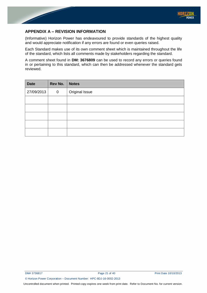
APPENDIX A – REVISION INFORMATION
(Informative) Horizon Power has endeavoured to provide standards of the highest quality and would appreciate notification if any errors are found or even queries raised.
Each Standard makes use of its own comment sheet which is maintained throughout the life of the standard, which lists all comments made by stakeholders regarding the standard.
A comment sheet found in DM: 3676809 can be used to record any errors or queries found in or pertaining to this standard, which can then be addressed whenever the standard gets reviewed.
Date Rev No. Notes
27/09/2013 0 Original Issue
DM# 3736817 Page 22 of 40 Print Date 10/10/2013
© Horizon Power Corporation – Document Number: HPC-8DJ-16-0002-2013
Uncontrolled document when printed. Printed copy expires one week from print date. Refer to Document No. for current version.
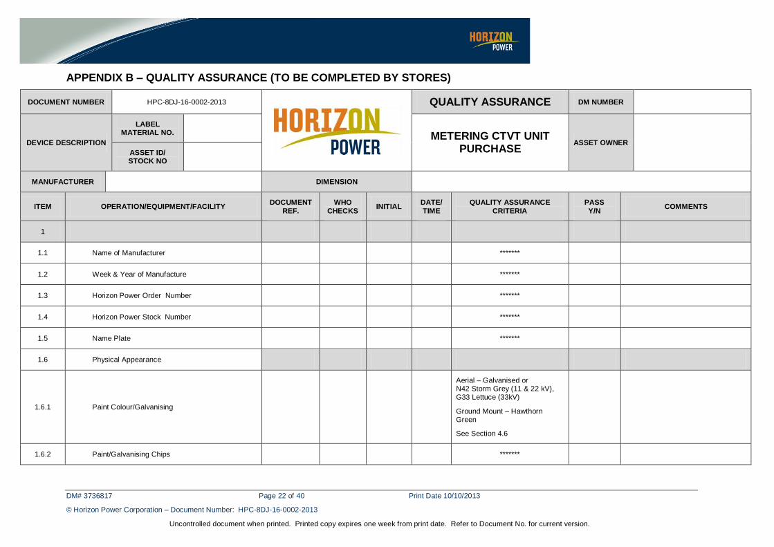
APPENDIX B – QUALITY ASSURANCE (TO BE COMPLETED BY STORES)
DOCUMENT NUMBER HPC-8DJ-16-0002-2013
QUALITY ASSURANCE DM NUMBER
DEVICE DESCRIPTION
LABEL MATERIAL NO.
METERING CTVT UNIT PURCHASE
ASSET OWNER
ASSET ID/ STOCK NO
MANUFACTURER DIMENSION
ITEM OPERATION/EQUIPMENT/FACILITY DOCUMENT
REF.
WHO
CHECKS INITIAL
DATE/
TIME
QUALITY ASSURANCE
CRITERIA
PASS
Y/N COMMENTS
1
1.1 Name of Manufacturer *******
1.2 Week & Year of Manufacture *******
1.3 Horizon Power Order Number *******
1.4 Horizon Power Stock Number *******
1.5 Name Plate *******
1.6 Physical Appearance
1.6.1 Paint Colour/Galvanising
Aerial – Galvanised or N42 Storm Grey (11 & 22 kV), G33 Lettuce (33kV)
Ground Mount – Hawthorn Green
See Section 4.6
1.6.2 Paint/Galvanising Chips *******
DM# 3736817 Page 23 of 40 Print Date 10/10/2013
© Horizon Power Corporation – Document Number: HPC-8DJ-16-0002-2013
Uncontrolled document when printed. Printed copy expires one week from print date. Refer to Document No. for current version.
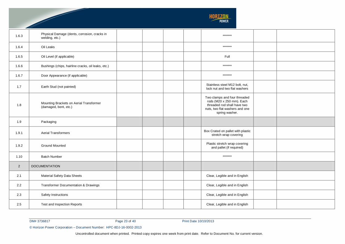
1.6.3 Physical Damage (dents, corrosion, cracks in welding, etc.)
*******
1.6.4 Oil Leaks *******
1.6.5 Oil Level (if applicable) Full
1.6.6 Bushings (chips, hairline cracks, oil leaks, etc.) *******
1.6.7 Door Appearance (if applicable) *******
1.7 Earth Stud (not painted) Stainless steel M12 bolt, nut,
lock nut and two flat washers
1.8 Mounting Brackets on Aerial Transformer (damaged, bent, etc.)
Two clamps and four threaded
rods (M20 x 250 mm). Each threaded rod shall have two
nuts, two flat washers and one
spring washer.
1.9 Packaging
1.9.1 Aerial Transformers Box Crated on pallet with plastic
stretch wrap covering
1.9.2 Ground Mounted Plastic stretch wrap covering
and pallet (if required)
1.10 Batch Number *******
2 DOCUMENTATION
2.1 Material Safety Data Sheets Clear, Legible and in English
2.2 Transformer Documentation & Drawings Clear, Legible and in English
2.3 Safety Instructions Clear, Legible and in English
2.5 Test and Inspection Reports Clear, Legible and in English
DM# 3736817 Page 24 of 40 Print Date 10/10/2013
© Horizon Power Corporation – Document Number: HPC-8DJ-16-0002-2013
Uncontrolled document when printed. Printed copy expires one week from print date. Refer to Document No. for current version.
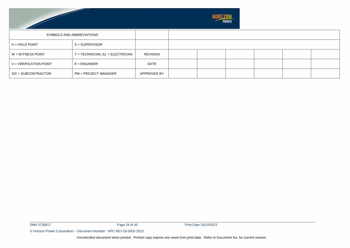
SYMBOLS AND ABBREVIATIONS
H = HOLD POINT S = SUPERVISOR
W = WITNESS POINT T = TECHNICIAN, EL = ELECTRICIAN REVISION
V = VERIFICATION POINT E = ENGINEER DATE
S/C = SUBCONTRACTOR PM = PROJECT MANAGER APPROVED BY
DM# 3736817 Page 25 of 40 Print Date 10/10/2013
© Horizon Power Corporation – Document Number: HPC-8DJ-16-0002-2013
Uncontrolled document when printed. Printed copy expires one week from print date. Refer to Document No. for current version.
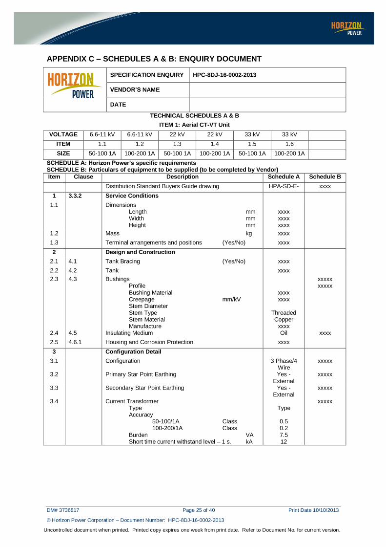
APPENDIX C – SCHEDULES A & B: ENQUIRY DOCUMENT
SPECIFICATION ENQUIRY HPC-8DJ-16-0002-2013
VENDOR’S NAME
DATE
TECHNICAL SCHEDULES A & B
ITEM 1: Aerial CT-VT Unit
VOLTAGE 6.6-11 kV 6.6-11 kV 22 kV 22 kV 33 kV 33 kV
ITEM 1.1 1.2 1.3 1.4 1.5 1.6
SIZE 50-100 1A 100-200 1A 50-100 1A 100-200 1A 50-100 1A 100-200 1A
SCHEDULE A: Horizon Power’s specific requirements SCHEDULE B: Particulars of equipment to be supplied (to be completed by Vendor)
Item Clause Description Schedule A Schedule B
Distribution Standard Buyers Guide drawing HPA-SD-E- xxxx
1 3.3.2 Service Conditions
1.1 Dimensions Length mm Width mm Height mm
xxxx xxxx xxxx
1.2 Mass kg xxxx
1.3 Terminal arrangements and positions (Yes/No) xxxx
2 Design and Construction
2.1 4.1 Tank Bracing (Yes/No) xxxx
2.2 4.2 Tank xxxx
2.3 4.3 Bushings Profile Bushing Material Creepage mm/kV Stem Diameter Stem Type Stem Material Manufacture
xxxx xxxx
Threaded Copper
xxxx
xxxxx xxxxx
2.4 4.5 Insulating Medium Oil xxxx
2.5 4.6.1 Housing and Corrosion Protection xxxx
3 Configuration Detail
3.1 Configuration 3 Phase/4 Wire
xxxxx
3.2 Primary Star Point Earthing Yes - External
xxxxx
3.3 Secondary Star Point Earthing Yes - External
xxxxx
3.4 Current Transformer Type Accuracy 50-100/1A Class 100-200/1A Class Burden VA Short time current withstand level – 1 s. kA
Type
0.5 0.2 7.5 12
xxxxx
DM# 3736817 Page 26 of 40 Print Date 10/10/2013
© Horizon Power Corporation – Document Number: HPC-8DJ-16-0002-2013
Uncontrolled document when printed. Printed copy expires one week from print date. Refer to Document No. for current version.
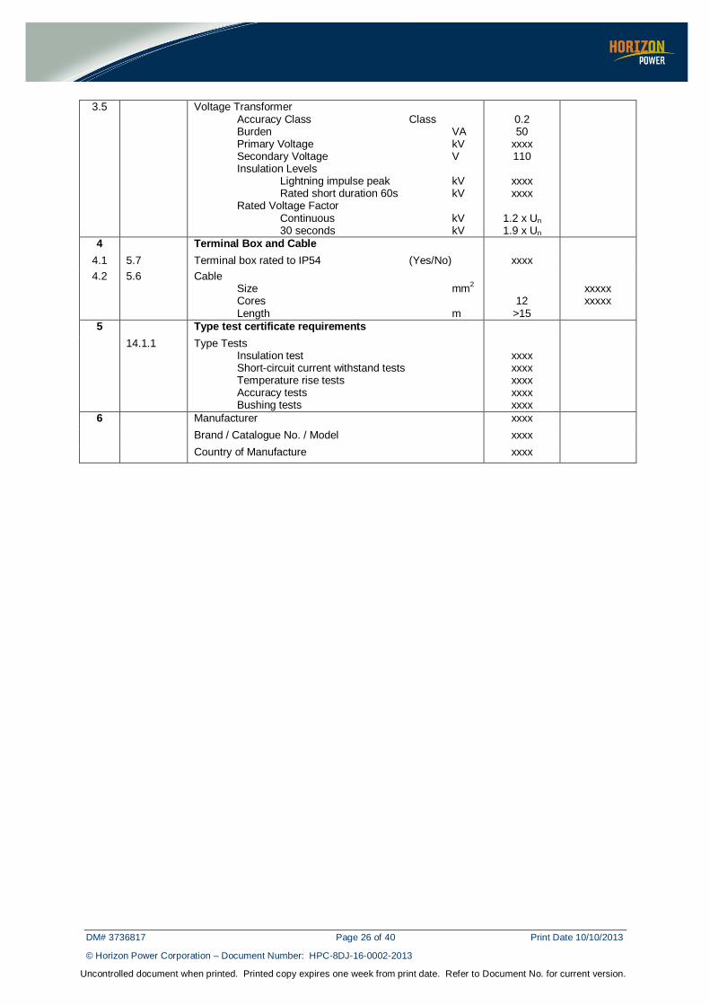
3.5 Voltage Transformer Accuracy Class Class Burden VA Primary Voltage kV Secondary Voltage V Insulation Levels Lightning impulse peak kV Rated short duration 60s kV Rated Voltage Factor Continuous kV 30 seconds kV
0.2 50
xxxx 110
xxxx xxxx
1.2 x Un 1.9 x Un
4 Terminal Box and Cable
4.1 5.7 Terminal box rated to IP54 (Yes/No) xxxx
4.2 5.6 Cable Size mm
2
Cores Length m
12 >15
xxxxx xxxxx
5 Type test certificate requirements
14.1.1 Type Tests Insulation test Short-circuit current withstand tests Temperature rise tests Accuracy tests Bushing tests
xxxx xxxx xxxx xxxx xxxx
6 Manufacturer xxxx
Brand / Catalogue No. / Model xxxx
Country of Manufacture xxxx
DM# 3736817 Page 27 of 40 Print Date 10/10/2013
© Horizon Power Corporation – Document Number: HPC-8DJ-16-0002-2013
Uncontrolled document when printed. Printed copy expires one week from print date. Refer to Document No. for current version.
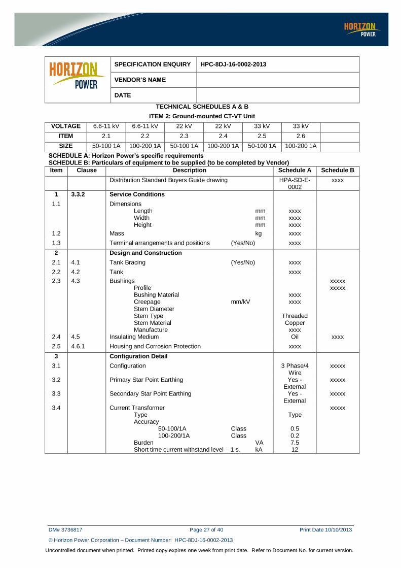
SPECIFICATION ENQUIRY HPC-8DJ-16-0002-2013
VENDOR’S NAME
DATE
TECHNICAL SCHEDULES A & B
ITEM 2: Ground-mounted CT-VT Unit
VOLTAGE 6.6-11 kV 6.6-11 kV 22 kV 22 kV 33 kV 33 kV
ITEM 2.1 2.2 2.3 2.4 2.5 2.6
SIZE 50-100 1A 100-200 1A 50-100 1A 100-200 1A 50-100 1A 100-200 1A
SCHEDULE A: Horizon Power’s specific requirements SCHEDULE B: Particulars of equipment to be supplied (to be completed by Vendor)
Item Clause Description Schedule A Schedule B
Distribution Standard Buyers Guide drawing HPA-SD-E-0002
xxxx
1 3.3.2 Service Conditions
1.1 Dimensions Length mm Width mm Height mm
xxxx xxxx xxxx
1.2 Mass kg xxxx
1.3 Terminal arrangements and positions (Yes/No) xxxx
2 Design and Construction
2.1 4.1 Tank Bracing (Yes/No) xxxx
2.2 4.2 Tank xxxx
2.3 4.3 Bushings Profile Bushing Material Creepage mm/kV Stem Diameter Stem Type Stem Material Manufacture
xxxx xxxx
Threaded Copper
xxxx
xxxxx xxxxx
2.4 4.5 Insulating Medium Oil xxxx
2.5 4.6.1 Housing and Corrosion Protection xxxx
3 Configuration Detail
3.1 Configuration 3 Phase/4 Wire
xxxxx
3.2 Primary Star Point Earthing Yes - External
xxxxx
3.3 Secondary Star Point Earthing Yes - External
xxxxx
3.4 Current Transformer Type Accuracy 50-100/1A Class 100-200/1A Class Burden VA Short time current withstand level – 1 s. kA
Type
0.5 0.2 7.5 12
xxxxx
DM# 3736817 Page 28 of 40 Print Date 10/10/2013
© Horizon Power Corporation – Document Number: HPC-8DJ-16-0002-2013
Uncontrolled document when printed. Printed copy expires one week from print date. Refer to Document No. for current version.
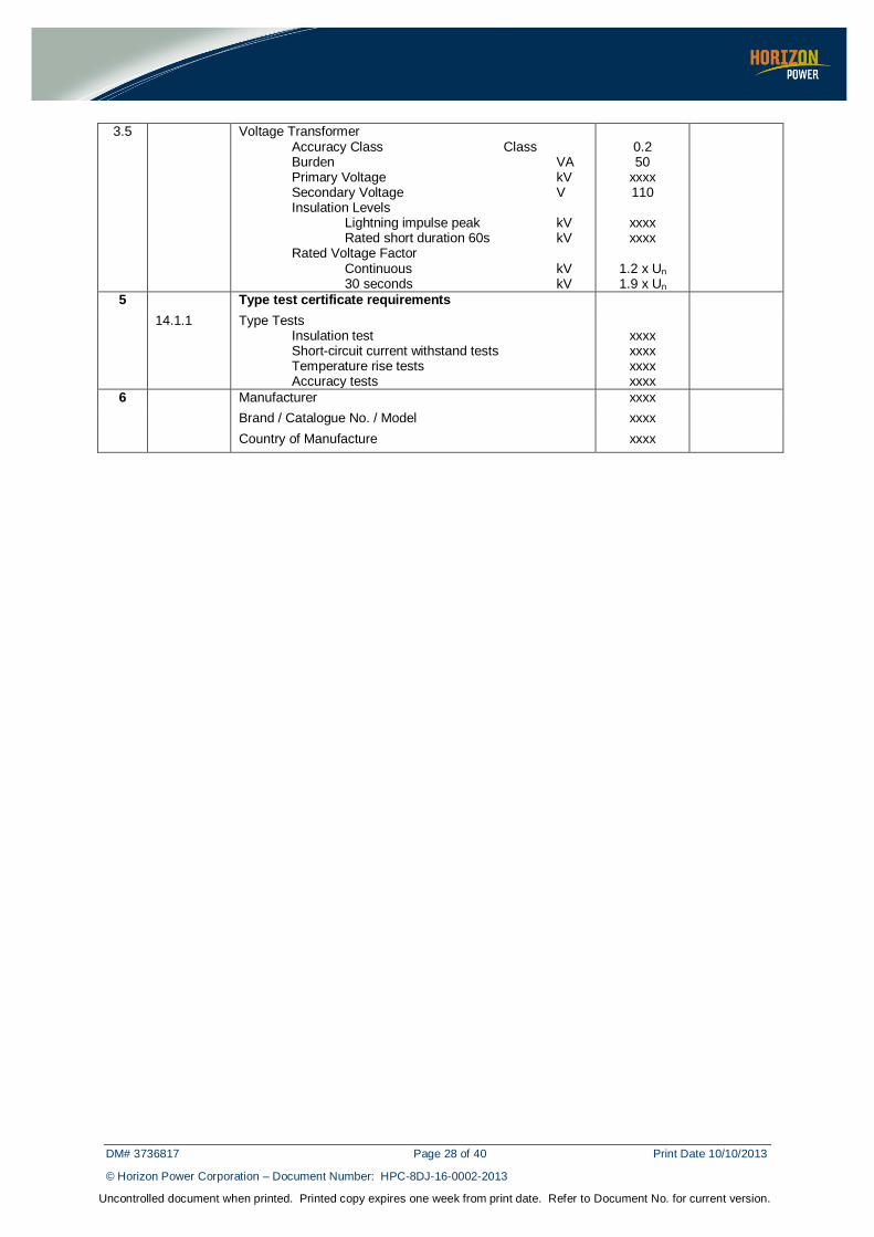
3.5 Voltage Transformer Accuracy Class Class Burden VA Primary Voltage kV Secondary Voltage V Insulation Levels Lightning impulse peak kV Rated short duration 60s kV Rated Voltage Factor Continuous kV 30 seconds kV
0.2 50
xxxx 110
xxxx xxxx
1.2 x Un 1.9 x Un
5 Type test certificate requirements
14.1.1 Type Tests Insulation test Short-circuit current withstand tests Temperature rise tests Accuracy tests
xxxx xxxx xxxx xxxx
6 Manufacturer xxxx
Brand / Catalogue No. / Model xxxx
Country of Manufacture xxxx
DM# 3736817 Page 29 of 40 Print Date 10/10/2013
© Horizon Power Corporation – Document Number: HPC-8DJ-16-0002-2013
Uncontrolled document when printed. Printed copy expires one week from print date. Refer to Document No. for current version.
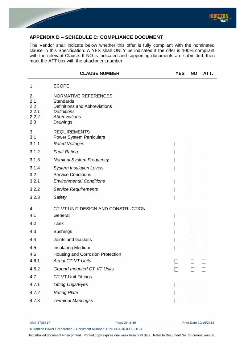
APPENDIX D – SCHEDULE C: COMPLIANCE DOCUMENT
The Vendor shall indicate below whether this offer is fully compliant with the nominated clause in this Specification. A YES shall ONLY be indicated if the offer is 100% compliant with the relevant Clause. If NO is indicated and supporting documents are submitted, then mark the ATT box with the attachment number
CLAUSE NUMBER YES NO ATT.
1. SCOPE
2. NORMATIVE REFERENCES 2.1 Standards 2.2 Definitions and Abbreviations 2.2.1 Definitions 2.2.2 Abbreviations 2.3 Drawings
3 REQUIREMENTS 3.1 Power System Particulars
3.1.1 Rated Voltages 3.1.2 Fault Rating 3.1.3 Nominal System Frequency 3.1.4 System Insulation Levels 3.2 Service Conditions
3.2.1 Environmental Conditions 3.2.2 Service Requirements 3.2.3 Safety
4 CT-VT UNIT DESIGN AND CONSTRUCTION
4.1 General 4.2 Tank 4.3 Bushings 4.4 Joints and Gaskets 4.5 Insulating Medium 4.6 Housing and Corrosion Protection
4.6.1 Aerial CT-VT Units 4.6.2 Ground-mounted CT-VT Units 4.7 CT-VT Unit Fittings 4.7.1 Lifting Lugs/Eyes 4.7.2 Rating Plate 4.7.3 Terminal Markingss
DM# 3736817 Page 30 of 40 Print Date 10/10/2013
© Horizon Power Corporation – Document Number: HPC-8DJ-16-0002-2013
Uncontrolled document when printed. Printed copy expires one week from print date. Refer to Document No. for current version.
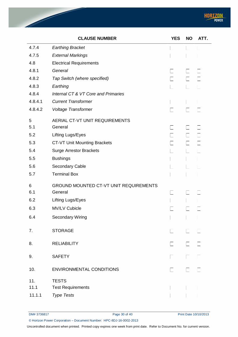
CLAUSE NUMBER YES NO ATT.
4.7.4 Earthing Bracket 4.7.5 External Markings 4.8 Electrical Requirements 4.8.1 General 4.8.2 Tap Switch (where specified) 4.8.3 Earthing 4.8.4 Internal CT & VT Core and Primaries 4.8.4.1 Current Transformer 4.8.4.2 Voltage Transformer
5 AERIAL CT-VT UNIT REQUIREMENTS
5.1 General 5.2 Lifting Lugs/Eyes 5.3 CT-VT Unit Mounting Brackets 5.4 Surge Arrestor Brackets 5.5 Bushings 5.6 Secondary Cable 5.7 Terminal Box 6 GROUND MOUNTED CT-VT UNIT REQUIREMENTS
6.1 General 6.2 Lifting Lugs/Eyes 6.3 MV/LV Cubicle
6.4 Secondary Wiring
7. STORAGE
8. RELIABILITY
9. SAFETY
10. ENVIRONMENTAL CONDITIONS 11. TESTS
11.1 Test Requirements 11.1.1 Type Tests
DM# 3736817 Page 31 of 40 Print Date 10/10/2013
© Horizon Power Corporation – Document Number: HPC-8DJ-16-0002-2013
Uncontrolled document when printed. Printed copy expires one week from print date. Refer to Document No. for current version.
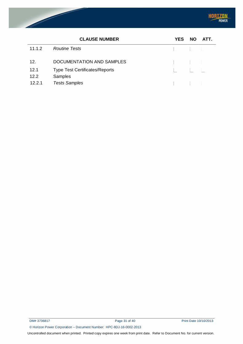
CLAUSE NUMBER YES NO ATT.
11.1.2 Routine Tests
12. DOCUMENTATION AND SAMPLES 12.1 Type Test Certificates/Reports 12.2 Samples
12.2.1 Tests Samples
DM# 3736817 Page 32 of 40 Print Date 10/10/2013
© Horizon Power Corporation – Document Number: HPC-8DJ-16-0002-2013
Uncontrolled document when printed. Printed copy expires one week from print date. Refer to Document No. for current version.
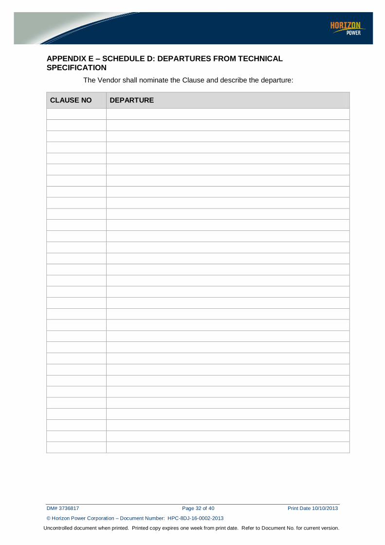
APPENDIX E – SCHEDULE D: DEPARTURES FROM TECHNICAL SPECIFICATION
The Vendor shall nominate the Clause and describe the departure:
CLAUSE NO DEPARTURE
DM# 3736817 Page 33 of 40 Print Date 10/10/2013
© Horizon Power Corporation – Document Number: HPC-8DJ-16-0002-2013
Uncontrolled document when printed. Printed copy expires one week from print date. Refer to Document No. for current version.
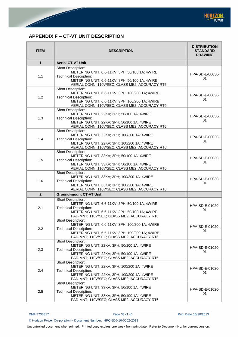
APPENDIX F – CT-VT UNIT DESCRIPTION
ITEM DESCRIPTION DISTRIBUTION
STANDARD DRAWING
1 Aerial CT-VT Unit
1.1
Short Description: METERING UNIT, 6.6-11KV; 3PH; 50/100 1A; 4WIRE Technical Description: METERING UNIT, 6.6-11KV; 3PH; 50/100 1A; 4WIRE AERIAL CONN; 110V/SEC; CLASS ME2; ACCURACY RT6
HPA-SD-E-00030-01
1.2
Short Description: METERING UNIT, 6.6-11KV; 3PH; 100/200 1A; 4WIRE Technical Description: METERING UNIT, 6.6-11KV; 3PH; 100/200 1A; 4WIRE AERIAL CONN; 110V/SEC; CLASS ME2; ACCURACY RT6
HPA-SD-E-00030-01
1.3
Short Description: METERING UNIT, 22KV; 3PH; 50/100 1A; 4WIRE Technical Description: METERING UNIT, 22KV; 3PH; 50/100 1A; 4WIRE AERIAL CONN; 110V/SEC; CLASS ME2; ACCURACY RT6
HPA-SD-E-00030-01
1.4
Short Description: METERING UNIT, 22KV; 3PH; 100/200 1A; 4WIRE Technical Description: METERING UNIT, 22KV; 3PH; 100/200 1A; 4WIRE AERIAL CONN; 110V/SEC; CLASS ME2; ACCURACY RT6
HPA-SD-E-00030-01
1.5
Short Description: METERING UNIT, 33KV; 3PH; 50/100 1A; 4WIRE Technical Description: METERING UNIT, 33KV; 3PH; 50/100 1A; 4WIRE AERIAL CONN; 110V/SEC; CLASS ME2; ACCURACY RT6
HPA-SD-E-00030-01
1.6
Short Description: METERING UNIT, 33KV; 3PH; 100/200 1A; 4WIRE Technical Description: METERING UNIT, 33KV; 3PH; 100/200 1A; 4WIRE AERIAL CONN; 110V/SEC; CLASS ME2; ACCURACY RT6
HPA-SD-E-00030-01
2 Ground-mount CT-VT Unit
2.1
Short Description: METERING UNIT, 6.6-11KV; 3PH; 50/100 1A; 4WIRE Technical Description: METERING UNIT, 6.6-11KV; 3PH; 50/100 1A; 4WIRE PAD-MNT; 110V/SEC; CLASS ME2; ACCURACY RT6
HPA-SD-E-01020-01
2.2
Short Description: METERING UNIT, 6.6-11KV; 3PH; 100/200 1A; 4WIRE Technical Description: METERING UNIT, 6.6-11KV; 3PH; 100/200 1A; 4WIRE PAD-MNT; 110V/SEC; CLASS ME2; ACCURACY RT6
HPA-SD-E-01020-01
2.3
Short Description: METERING UNIT, 22KV; 3PH; 50/100 1A; 4WIRE Technical Description: METERING UNIT, 22KV; 3PH; 50/100 1A; 4WIRE PAD-MNT; 110V/SEC; CLASS ME2; ACCURACY RT6
HPA-SD-E-01020-01
2.4
Short Description: METERING UNIT, 22KV; 3PH; 100/200 1A; 4WIRE Technical Description: METERING UNIT, 22KV; 3PH; 100/200 1A; 4WIRE PAD-MNT; 110V/SEC; CLASS ME2; ACCURACY RT6
HPA-SD-E-01020-01
2.5
Short Description: METERING UNIT, 33KV; 3PH; 50/100 1A; 4WIRE Technical Description: METERING UNIT, 33KV; 3PH; 50/100 1A; 4WIRE PAD-MNT; 110V/SEC; CLASS ME2; ACCURACY RT6
HPA-SD-E-01020-01

DM# 3736817 Page 34 of 40 Print Date 10/10/2013
© Horizon Power Corporation – Document Number: HPC-8DJ-16-0002-2013
Uncontrolled document when printed. Printed copy expires one week from print date. Refer to Document No. for current version.
ITEM DESCRIPTION DISTRIBUTION
STANDARD DRAWING
2.6
Short Description: METERING UNIT, 33KV; 3PH; 100/200 1A; 4WIRE Technical Description: METERING UNIT, 33KV; 3PH; 100/200 1A; 4WIRE PAD-MNT; 110V/SEC; CLASS ME2; ACCURACY RT6
HPA-SD-E-01020-01
DM# 3736817 Page 35 of 40 Print Date 10/10/2013
© Horizon Power Corporation – Document Number: HPC-8DJ-16-0002-2013
Uncontrolled document when printed. Printed copy expires one week from print date. Refer to Document No. for current version.
APPENDIX G – SPECIFICATION DRAWINGS
DM# 3736817 Page 36 of 40 Print Date 10/10/2013
© Horizon Power Corporation – Document Number: HPC-8DJ-16-0002-2013
Uncontrolled document when printed. Printed copy expires one week from print date. Refer to Document No. for current version.
DM# 3736817 Page 37 of 40 Print Date 10/10/2013
© Horizon Power Corporation – Document Number: HPC-8DJ-16-0002-2013
Uncontrolled document when printed. Printed copy expires one week from print date. Refer to Document No. for current version.
DM# 3736817 Page 38 of 40 Print Date 10/10/2013
© Horizon Power Corporation – Document Number: HPC-8DJ-16-0002-2013
Uncontrolled document when printed. Printed copy expires one week from print date. Refer to Document No. for current version.
DM# 3736817 Page 39 of 40 Print Date 10/10/2013
© Horizon Power Corporation – Document Number: HPC-8DJ-16-0002-2013
Uncontrolled document when printed. Printed copy expires one week from print date. Refer to Document No. for current version.
DM# 3736817 Page 40 of 40 Print Date 10/10/2013
© Horizon Power Corporation – Document Number: HPC-8DJ-16-0002-2013
Uncontrolled document when printed. Printed copy expires one week from print date. Refer to Document No. for current version.