"sonic-boom minimization with nose-bluntness relaxation" · pdf filenose-bluntness...
TRANSCRIPT
NASA Technical Paper 1348
Sonic-Boom Minimization With _
Nose-Bluntness Relaxation
Christine M. Darden
m
; E
• Bmmmm
BE
B
m
• mmwm
E
• " U
m
i
-,|
n
!
i|
!
r_maaaaaaaam,.m
https://ntrs.nasa.gov/search.jsp?R=19790006829 2018-05-25T17:32:14+00:00Z
=
|R
mi

NASA Technical Paper 1348
Sonic-Boom Minimization
Nose-Bluntness Relaxation
With
Christine M. Darden
Langley Research Center
Hampton, Virginia
NILSANational Aeronautics
and Space Administration
Scientific and Technical
Information Office
1979

SUMMARY
A method which provides sonic-boom-minimizing equivalent area distributions
for supersonic cruise conditions is described. This work extends previous anal-
yses to permit relaxation of the extreme nose bluntness which is required by
conventional low-boom shapes and includes propagation in a real atmosphere.
The procedure provides area distributions which minimize either shock strength
or overpressure. The minimizing Whitham F-functions for the pressure signaturesare also included.
INTRODUCTION
Sonic-boom levels produced by future generation supersonic transports must
be considered if their supersonic flight paths, and thus their economic success,
are not to be severely restricted. It is generally believed that the best
approach to this problem is to include low-boom constraints early in the design
process. The procedure described herein provides this constraint in the form
of an equivalent area distribution which depends on the design conditions of
aircraft weight (lift) and length, and on cruise Mach number and altitude.
Sonic-boom-minimization studies, by Jones, Seebass, and George for uniform
and isothermal atmospheres have been reported in references I to 6. These anal-
yses have been extended to a real atmosphere in reference 7. All these studies
have indicated that the minimizing area distribution is characterized by a blunt-
ness in the leading portion of the area distribution, i.e., the aircraft nose
region. Because extreme nose bluntness produces large drag, a method of relaxing
the bluntness requirement is needed to offer the opportunity for compromise between
blunt-nose, low-boom and sharp-nose, low-drag configurations.
This analysis extends the work of Seebass and George (ref. 6) and Darden
(ref. 7) to include nose-bluntness relaxation. Because questions still remain
regarding the type of pressure signature and the level of overpressure which
are acceptable, either a minimum-shock or a minimum-overpressure signature may
be produced for given cruise conditions and nose length.
This analysis has been incorporated into a computer program which is
described in the appendix of this paper.
SYMBOLS
Although values are given in both SI and U.S. Customary Units, the calcu-
lations for the investigation were made in U.S. Customary Units.
Notation used in the computer printout is given in parentheses.
A
Ae
Ae(l )
a
B
C
CD
D
ray-tube area
equivalent area
equivalent area at equivalent length I
speed of sound
slope of rise in F-function (eq. (20))
height of F-function at balancing point
drag coefficient
constant in F-function equation
F (F and FTAU)
G
H
h (Z)
I
K (RFK)
z (L)
M
P
P
S
t
u
V
W (WG)
w (W-TILDE)
Whitham F-function
area of F-function to front balance point
height of spike in F-function
airplane altitude
impulse of pressure signature, 1 P dt
_p >0
reflection factor
equivalent length of airplane
Mach number
pressure perturbation
ambient pressure
Ap (Delta P) overpressure
slope of balancing line
time
speed
total area, _W/pu 2
airplane weight
weight parameter,
V
B(Z - yf) 5/2
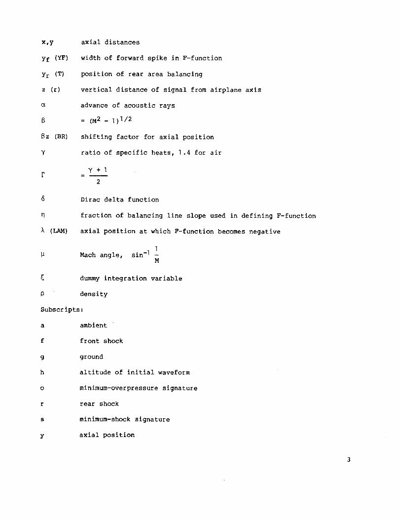
x,y
yf (YF)
Yr (T)
z (r)
8z (BR)
Y
F
8
n
(LAM)
axial distances
width of forward spike in F-function
position of rear area balancing
vertical distance of signal from airplane axis
advance of acoustic rays
= (S 2 _ ] )I/2
shifting factor for axial position
ratio of specific heats, 1.4 for air
y+1
2
Dirac delta function
fraction of balancing line slope used in defining F-function
axial position at which F-function becomes negative
]
Mach angle, sin -] -M
dummy integration variable
density
Subscripts:
a
f
g
h
o
r
s
Y
ambient
front shock
ground
altitude of initial waveform
minimum-overpressure signature
rear shock
minimum-shock signature
axial position

yf axial position of front area_balance
z vertical distance of signal from airplane axis
First and second derivatives with respect to distance are denoted by singleand double primes, respectively.
BACKGROUND
Sonic-boom-minimization studies are based primarily on currently acceptedsonic-boom prediction methods. Thesemethods, outlined in figure I, are exten-sions of work done by Whitham (ref. 8), Walkden (ref. 9), and Hayes (ref. ]0).
From the complex aircraft configuration and its lift distribution, an equivalent
area distribution is defined. This equivalent area distribution then defines
the Whitham "F-function" through the following integral relation:
] _0 y Ae" d_F(y) 2_ (y _ _)1/2
(])
This F-function represents a distribution of sources which causes the same dis-
turbances as the aircraft at some distance from the aircraft.
Because the pressure signal propagates at the local speed of sound, and
each point of the signal advances according to its amplitude, the signal is dis-
torted at the ground and, theoretically, can be multivalued. The physically
unrealistic multiple values of pressure are, however, eliminated by the intro-
duction of shocks. Shock location, based on the observation that for weak dis-
turbances the shock bisects the angle between two merging characteristic lines,
is determined by a balancing of the signature areas within loops on either side
of the shocks. This procedure is demonstrated by the shaded areas of the dis-
torted signal in figure 1.
For present-day supersonic aircraft, the propagation distance (altitude)
and the pattern of shock coalescence have been such that, at ground level, only
two shocks remain in the signature. These two shocks have a linear pressure
variation between them (as seen in fig. 2), thus the name "far-field N-wave."
For this wave, the shape of the generating aircraft has an effect on the magni-
tude but no effect on the shape of the resulting signature. For a sufficiently
long and slender aircraft, it was found that the ground wave form may possibly
not have attained its N-shape remaining instead a mid-field wave. Because the
shape of the aircraft does influence the shape of a mid-field pressure signature,
aircraft shaping has now become a powerful tool in reducing the sonic boom.
The F-functions for the lower bound of an N-wave (refs. I and 2) and for
the lower bound of the bow shock in a mid-field signature (refs. 3 and 4) led
to the form of the minimizing F-function assumed by Seebass and George for the
entire signature. Lung (ref. 11) later proved this to be the minimizing form
by "bang-bang" control theory.
4

Commonto all of these minimizing forms of the F-function is a Dirac delta
function at y = 0. This infinite impulse corresponds to an infinite gradient
at the nose of the equivalent area distribution. Aircraft designed to match
these area distributions generally have extremely blunt nose shapes which result
in substantial drag. This result, though seemingly paradoxical, can be explained
by the created shock-attenuation pattern in which the shock strengths, and there-
fore the drag, are greatest near the aircraft. Because of special shaping and
area growth, secondary shocks from other aircraft components do not overtake and
enhance the bow shock during the propagation of the wave front. (See fig. 3.)
The net result of this process is weaker shocks at larger distances because of
attenuation, but an overall increase in drag. In contrast, notice that the bow
shock is weaker on the sharp-nosed aircraft, but coalescence with stronger shocks
from rearward components causes a much stronger shock at mid- and far-field dis-
tances. If an aircraft configuration is to incorporate boom-minimization features
and not suffer aerodynamic penalties which inordinately affect its flight effi-
ciency, range, payload, productivity, and so forth, then means must be provided
for including nose-bluntness sensitivity in design trade-off studies.
ANALYSIS
The following is a brief description of the Seebass-George minimization
scheme with modifications to provide propagation through the real atmosphere
(ref. 7) and control over the bluntness of the area distribution and thereby
the drag of the configuration. The assumed form for the class of minimizing
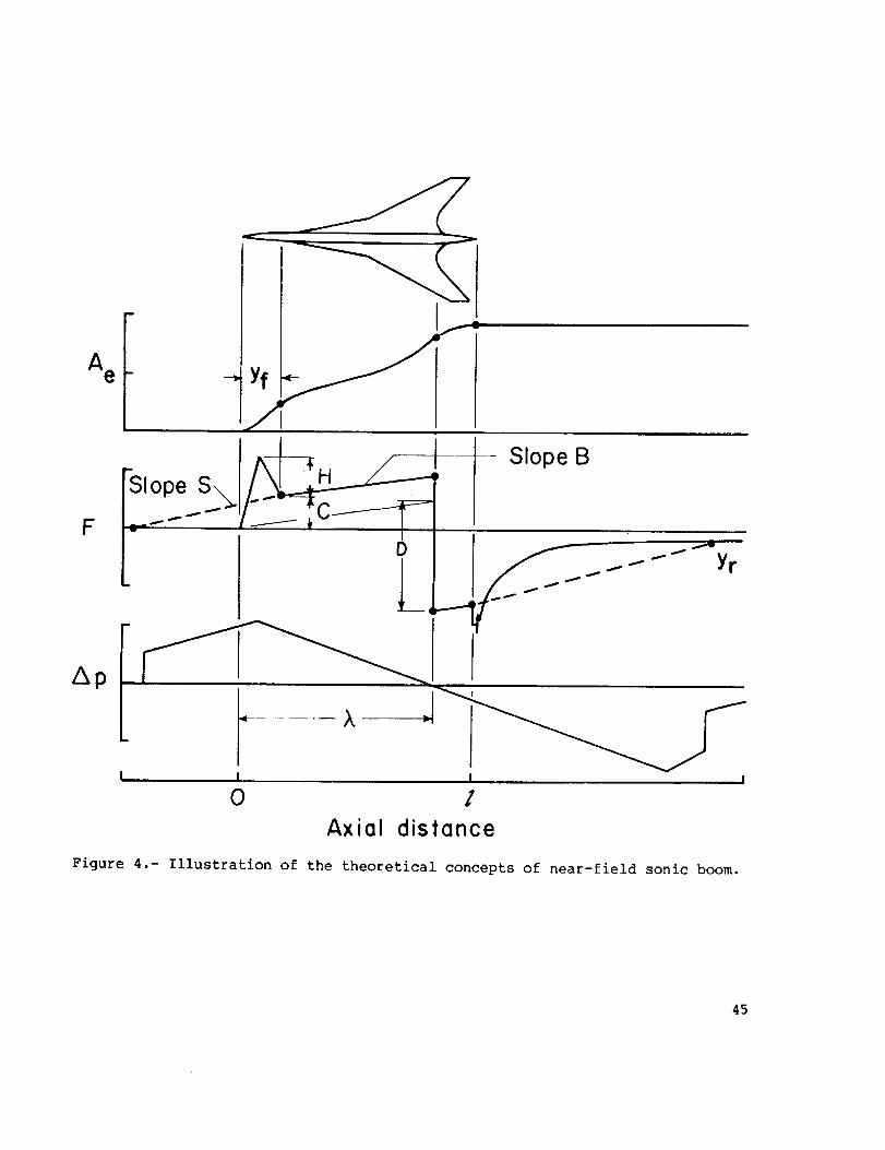
F-functions is shown in figure 4. In mathematical terms it may be expressed
as:
F(y) = 2yH/yf
F(y) = C(2y/yf - I) - H(2y/yf - 2)
F(y) = B(y - yf) + C
F(y) = B(y - yf) - D
(0 < y < yf/2) (2a)
(yf/2 < y < yf) (2b)
(yf < y < l) (2c)
(l _ y < l) (2d)
In these equations H, B, C, D, and _ are unknown coefficients which are
determined by the cruise conditions of the aircraft, by nose length, by the pre-
scribed ratio of bow to rear shock, and by the signature parameter being mini-
mized. Types of signatures studied include flat-topped signatures in which over-
pressure is minimized with B = 0 and signatures in which F(y) is allowed to
rise between yf and _ with a resulting minimum shock followed by a pressure
rise as illustrated in figure 4. The value of B in this form of F(y) may
range between 0 and S. Recall that the Whitham function F(y) represents the
shapecharacteristics of the pressure signature and is defined in reference ]0
and equation (1) in terms of the equivalent area distribution as:
d_

Crucial to this minimization technique is the fact that equation (I) is an Abel
integral equation which may be inverted to give the function A e in terms of
the F-function. When this function is evaluated at 2, the result is:
Ae(7 ) = 4 F(y) (Z - y)]/2 dy (3)
Upon substituting the minimizing form of the F-function into equation (3) and
integrating, the following equation for the development of cross-sectional area
is obtained:
A e (x) =
32 H
]5 yfx5/2 l<x Yfl 8- - + -
- - - (3yf + 2x) + --C3
'--("1 ' '+ (3yf + 2x) - --H + -- B(3yf + 2x) - --Byf + -15\yf/ 3 ]5 3 3
8- ] (x - l)-(x - I) 3/2(C + D) (4)
3
where ] (x - 7) is the Heaviside unit step function. A typical form of the
resulting area distribution, Ae, is seen in figure 4.
If the effects of aircraft wake and engine exhaust are neglected, and, if
the aircraft cross-section area is zero at its base, then the area at I is
entirely due to cruise lift or
W 32 H
Ae(1 ) = -- =pu 2 ] 5 yf
25/2 + __ - -- +
152Z (2C - 4H) + 5(2H - C
'--("--1 '+ 4(I - yf) 3/2 3yf + 21) + -- C + (3yf + 21) - - H
L_yf/ 3 ] 5\yf/ 3
2 2 2 8
+ -- B(3yf + 21) - - Byf + - C - -(I - X) 3/2(C + D)]5 3 3 3
(5)
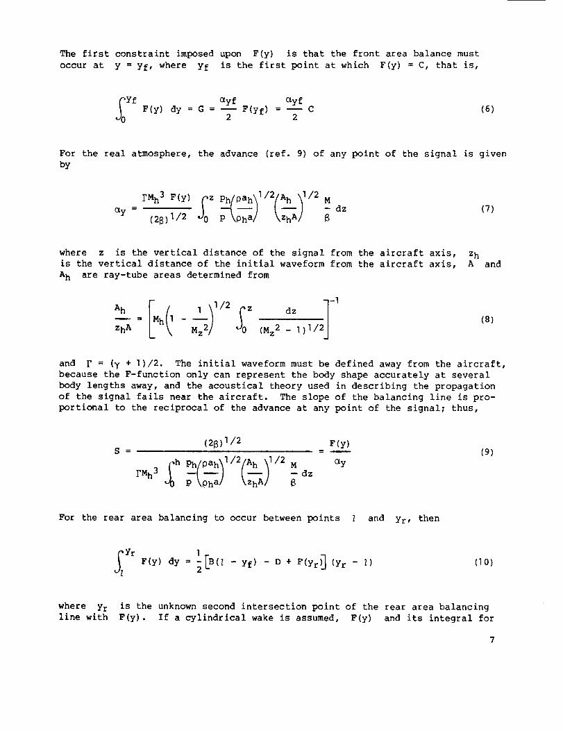
The first constraint imposed upon F(y) is that the front area balance must
occur at y = yf, where yf is the first point at which F(y) = C, that is,
_0 yf (_Yf (_yfF(y) dy = G = i F(yf) = I C
2 2(6)
For the real atmosphere, the advance (ref. 9) of any point of the signal is given
by
(28)I/2 P \Qha/ \ZhA/ 8
where z is the vertical distance of the signal from the aircraft axis, z h
is the vertical distance of the initial waveform from the aircraft axis, A and
A h are ray-tube areas determined from
Ah I I/2 z dz
Zh A h -- "(Sz2 - I)I/
(8)
and F = (y + I)/2. The initial waveform must be defined away from the aircraft,
because the F-function only can represent the body shape accurately at several
body lengths away, and the acoustical theory used in describing the propagation
of the signal fails near the aircraft. The slope of the balancing line is pro-
portional to the reciprocal of the advance at any point of the signal; thus,
(28) I/2 F(y)
S = = -- (9)
_h _pahll/2(A hzhAll/2M _yFMh3 _ \--/ -- dzP \Qha/
For the rear area balancing to occur between points _ and Yr, then
_Yr IF(y) dy = -(zFB - yf) - D + F(Yr__)J (Yr - _)
2(10)
where Yr is the unknown second intersection point of the rear area balancing
line with F(y). If a cylindrical wake is assumed, F(y) and its integral for

y > 2 can be expressed in terms of F(y)
as follows:
for y < 7 according to reference ]
F(y) = -] CZ (Z - _)]/2
1T(y - Z) ]/2 _ Y -
F(_) d_ (y > Z) (I])
2 _Z _/Yr - Z\ ]/2_Yr F(y)dY = - --IT F(_) tan-lk[ _-; d_(y > Z) (] 2)
It is necessary to define F(y) and its integral for y > _ in this way for
optimization problems, since aircraft geometry and thus the Whitham function
can be varied arbitrarily only in the range 0 _ y _ _. The constraint on the
ratio of shocks is given by
Pfw
Pr
C
D - B(Z - yf) + F(Yr)
(]3)
To insure that Yr is an intersection point of F(y)
then
F(Yr) = S(y r - _) + B(Z - yf) - D
and the balancing line,
(14)
and the slope of F(y) at Yr must be less than S.
Solving the system of equations ((5), (6), (]0), (13), and (14)) provides
values for the constants H, C, D, _, and Yr" One difficulty of this mini-
mization approach is that, as yet, there is no precise definition of the rise
time that will allow the ear to detect only the bow shock and not to be sensi-
tive to the peak as well. With the values of the coefficients known, the mini-
mizing F-function and the area distributions may be determined by equations (2)
and (4).
To convert F(y) into pressure near the airplane, the following equation
is used:
-a_ = yM2Fh (28Zh)]/2
(1 5)
and on the ground

( l''210gag Ij2pg = i Ph
\ Ag/ \Phah /
(16)
Finally, by using a ground reflection factor
converted into the ground signature by
K, the pressure perturbations are
Apg = PgK (]7)
The ground-level signature is presented by the signature shown in figure 4.
By taking the limit as yf ÷ 0 and by using L'Hospital's rule, the expres-
sion for area development given above (eq. (4)_ reduces to the following delta
function form as given by Seebass and George (ref. 6):
16 8 8
A e(x) = 4Gx I/2 + __ Bx5/2 + _ Cx3/2 _ ] (x - l)-(x - I)3/2(C + D)15 3 3
(18)
SPECIAL CASES
Special types of pressure signatures occur for large or small values of
~ ~ Bw Ithe weight parameter w, where w = -- . These special cases
pu 2 B(7 - yf) 5/2
include signatures with no bow shock, signatures with no shocks, and signatures
in which the rear shock is less than the bow shock without restriction (fig. 5).
Values of W may be checked to indicate when the special calculations are
necessary.
No Bow Shock
For no bow shock, the expression for total area reduces to the yf = 0
form (eq. (18)) automatically. Using the facts that G = _C 2 and _ = Z at
the minimum length necessary for no shock, the resulting quadratic in C may
be solved explicitly to give
where
C = -- -+ +
T] 3 15 2 BZ
8w 1
v=-- B = Sq S =-
pu 2
(0_<-n$1)
(]9)
(20)

For no bow shock (C = 0) equation (] 9) reduces to
V 16
BZ5/2 ] 5
(21)
in the minimum shock signature.
No Shocks
To eliminate both shock waves, G and C are zero and there must be no
discontinuity in F at Z. In fact, both F(y) and F'(y) must be continuous
at 7 and thus Ae'(X) and Ae"(x) must be zero there, since A e is constant
for x > 7. With no shocks,
16 8
Ae(_ ) = -- BZ5/2 - D(_ - i) 3/2 (22)15 3
By taking the first and second derivatives and solving the two resulting equa-
tions simultaneously
2=_ _ (23)
3
2nD = -- (24)
3e
Substituting these values back into the expression for A e gives
Vw : -- _< 0.47407 (25)
BI5/2
No Restriction on Rear Shock
Values of I < Z in the minimizing F-function result because of restric-
tions on the rear shock. For short lengths, high weights, etc., or other combina-
tions which give large values of W, the rear shock is less than the bow shock
I0

without restriction. In these instances I = 7 and the system of equations issolved without restricting the ratio of rear to front shock:
2yhF(y) = -- (0 < y < yf/2) (26a)
Yf
\Yf \Yf(yf/2 < y < yf) (26b)
F(y) = B(y - yf) + C (yf/2 _ y _ _) (26c)
Substituting this expression for F into equation (3) and integrating gives a
quadratic equation in C which can be solved explicitly. Values for C, h,
I, Z, and B are now established. For the rear area balance to occur at Yr
F(y) dy = 2[B(Z - yf) - D + F(Yr) 3 (Yr - _)(27)
also, Yr must be an intersection point for F(y) and balance point, or
F(Y r) = s(y r - Z) + B(Z - yf) - D (28)
Combining these equations
Yr F(y) dy
Yr- Z = (29)
]-[2F(Yr) - S(y r - i)_2
which may be solved iteratively for Yr with
] _Z (Z - _)1/2
F(Yr) = - _0 F(_) d_ (30)IT(yr _ _)I/2 Yr -
1]

and
:SO _<Yr 'llJ:F(y) dy : - - F(_) tan -I [ _- dE(31)
Substituting back into equation (28) gives the required value for D.
Values of w producing the special cases are shown in figure 5. Typical
values giving these extreme w's at M = 2.7, z = 18 288 m (60 000 ft),
W = 272 155 kg (600 000 Ib) would be Z = 33.5 m (]]0 ft) for no restriction
on the rear shock and Z = ]67.64 m (550 ft) for no bow shock. These values
may vary slightly with yf as seen.
TYPICAL RESULTS
Except as indicated otherwise, all results shown are for the following con-
ditions: Mach number, 2.7; altitude, 18 288 m (60 000 ft); weight, 272 155 kg
(600 000 ib); equivalent length, 91.44 m (300 ft); reflection factor, 2.0; ratio
of bow to rear shock pressure, ]; and B = 0.5S. The value of the front balancing
point yf determines the length of the conical nose region of the equivalent area
distribution and is the controlling factor for drag when all of the other flight
conditions remain constant. Referring again to figure 4, this position is indi-
cated On the F-function and the corresponding area distribution.
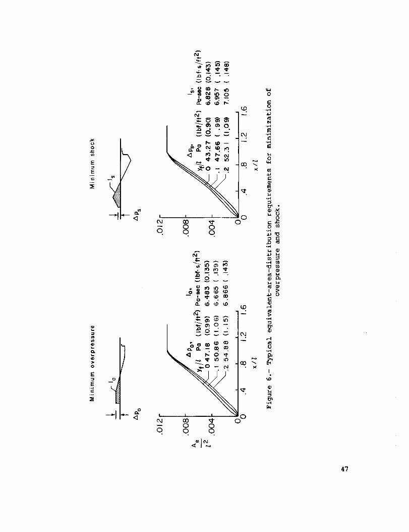
The effect that varying yf has on the equivalent area distributions for
both the minimum-shock and minimum-overpressure signatures is seen in figure 6.
Each of the distributions was determined from the inversion formula which defines
the effective area corresponding to the minimizing F-function for a given value
of yf. Values of the overpressure and impulse which correspond to these distri-
butions have been inserted for reference. Recall that the impulse is the integral
of the positive portion of the pressure signature, as indicated in the signatures
at the top of figure 6. Note that the lowest values of overpressure and impulse
for these conditions occur when the area distribution has an infinite gradient at
the nose. As yf increases, the longer conical nose region, generated to reduce
drag, also causes an increase in overpressure and impulse. Thus, extensive trade-
off studies between drag and boom levels would be necessary in any aircraft design
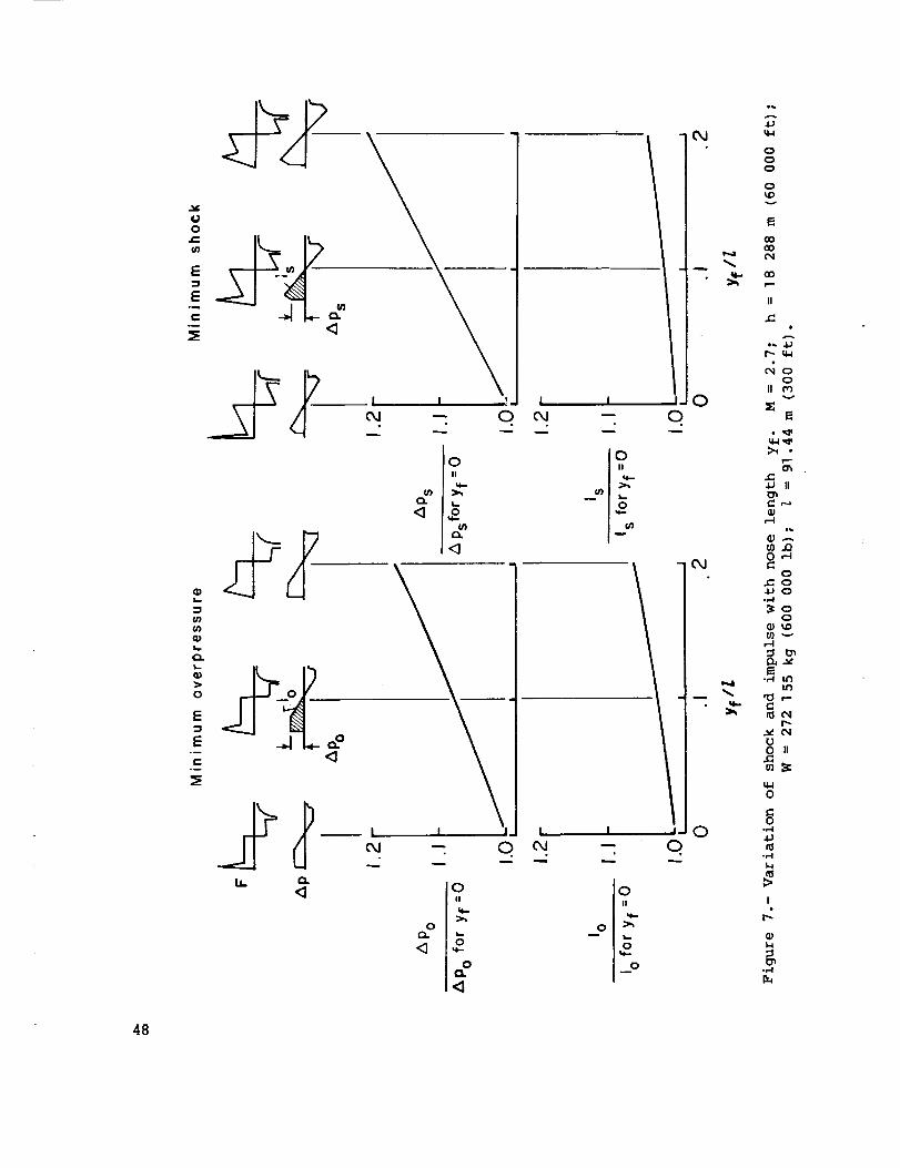
studies. The ratio of the increase in overpressure and impulse for both types of
signatures as a function of the ratio of nose length to airplane length yf/Z is
seen more easily in figure 7. With increasing values of yf, note that the area
under the peak portion of the F-function also increases but not in the same pro-
portions. Therefore, to achieve the necessary total area, the level of the con-
stant portion of the F-function also must increase, thereby producing a higher
level of Ap and I. For illustrative purposes, the nose spike of the F-function
for yf = 0 has been drawn with a finite width. For this condition, the spike is
defined mathematically as a pulse of zero width and infinite height which never-
theless has a finite area. In these figures, Ap is the level of overpressure at
the bow shock and represents the initial "bang" heard by the ear when a sonic boom
occurs.
12

The variations of overpressure level and the corresponding drag levels areseen in figure 8. To develop the corresponding variation of drag with yf, theassumption is madethat necessary configuration changes would be confined tothe fuselage forebody itself. The increment in drag produced by these changeswas calculated using the near-field program of reference 12 and then applied todrag values for a typical arrow-wing SSTconfiguration. As seen in figure 8,there is a sharp decline in drag as the blunt nose is converted to a conicalregion. Thus, the boomlevels could be reduced significantly without prohibi-tive drag penalties by defining the proper ratio yf/Z.
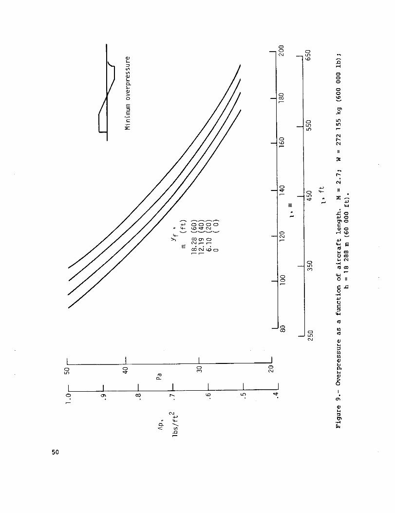
The actual trend of overpressure with length is seen in figure 9. The low-est curve represents the yf = 0 case, the higher ones increasing with yf.In all instances observe that overpressure levels decrease with length. Thoughthese results are for minimum-overpressure signatures, similar trends are foundto exist for the minimum-shocksignatures.
CONCLUDINGREMARKS
The analysis for a sonic-boom minimization method has been presented. The
method, which represents an extension of previous work, provides the minimizing
equivalent area distribution with relaxation of the nose-bluntness requirement
for given cruise conditions and includes propagation in the standard atmosphere.
The minimizing Whitham F-functions for the minimum-overpressure or minimum-shock
signature are also included.
Langley Research Center
National Aeronautics and Space Administration
Hampton, VA 23665
November 13, 1978
]3

APPENDIX
COMPUTER PROGRAM DESCRIPTION AND FLOW CHART
This program calculates the Whitham F-function and the corresponding equiv-
alent area distribution which produce the mlnimum-overpressure or minimum-shock
signature. The solution is based on five governing equations: total area growth
_eq. (5)), front area balancing point _eq. _6)), rear area balancing point
(eq. (10)), ratio of front to rear shock (eq. (13)), and the area balancing line
at the rear balancing point (eq. (]4)). These five equations reduce to two non-
linear equations in two unknowns which are solved iteratively using the Newton-
Raphson and a combination of the secant and bisection methods.
In calculating the advance of the wave front the standard atmosphere has
been used except for an area near the aircraft axis where it is necessary to
assume a uniform atmosphere.
This program was coded for the Control Data 6600 computer in Fortran IV.
The field length required is 100 000 octal units. Program SEEB is available
as LAR ]]979 from
COSMIC
Suite ]12 Barrow Hall
University of Georgia
Athens, GA 30602
The flow chart of program SEEB is on the following page.
M
Z
L
WG
YF
IPRINT
RKF
INPUT DESCRIPTION
Cruise Mach number (].25 to 3.0)
Cruise altitude (20 000 to ]00 000 ft (6096 to 30 480 m))
Airplane equivalent length (200 to 700 ft (60.96 to 213.36 m))
Gross weight of airplane (200 000 to ] 000 000 Ib (90 720 to
453 600 kg))
Balancing point in F-function to determine the front shock
(0 _ yf/Z _ 0.2) (Default = 0.0 delta function)
= 0 Iterations on Lambda and T not printed.
= ] Iterations printed.
(Default = 0)
Reflection factor.
(Default = 2.0.)
14

APPENDIX
InitializeProgram
LAM = 2/3LT = L
H = C = 0
' Interpolate
to find newL for givenDELTA P
itable
table
Read /
es
Calculate 1advance
Check
W-TILDE
shock
No bowshock or
regula
No bow
_,,,,ISHOCK
restrictioron rear shock
Iterateon T
Iterate onLAM
ition
Stop
LAM = Literate tofind T.
slg.
ILEN = NoI?
Firsttime?
,Yes
SlopeI?
Increment
slope
Yes
IS : O?
Decrease
15

BLEN
PRPF
WIWG
ISIG
IS
PERCEN
ICH
ILEN
IYF
APPENDIX
Factor determining where iteration on T begins.
(Default = 3.0)
T = BLEN- L
Ratio of rear to front shock
(Default = ].0)
Percentage of gross weight remaining at start of cruise.
W = WIWG'WG (Default = ].0)
= ] Area, F-function and pressure signature are printed.
= 0 Only the pressure signature is printed.
(Default = 0)
= 0 Minimum-shock and minimum-overpressure signatures.
= ] Minimum-overpressure signature only.
= 2 Minimum-shock signature only.
(Default = 0)
Factor determining the difference in the slope of the balancing line
and the rise portion of the minimum-shock F-function. Slope of rise
= Slope of balancing line minus PERCEN times slope of balancing line.
(Default = 0.5)
Indicates whether the altitude or Mach number changed after the initial
run and the advance must be recalculated.
= 0 No change.
= ] Mach number or altitude did change.
(Default = 0)
= 0 Find _p for given input conditions.
= ] Iterate to find lengths necessary to give Ap = 0.5, 0.6, 0.7,
0.8, 0.9, and i.0 psf. A full set of flight conditions includ-
ing length must be input.
(Default = 0)
= 0 Delta function used in F-function.
= I Nonzero value of yf used.
If the value of yf is less than I, the program automatically uses
the delta function in the F-function.
(Default = 1)
]6

APPENDIX
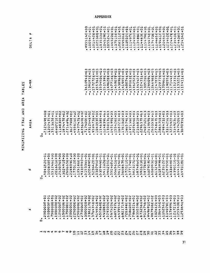
OUTPUT DESCRIPTION
The output consists of a listing of input conditions, the solution coeffi-
cients, solution tables, and summary values. Codes exist so that only the pres-
sure signature is printed, the F-function, area, and pressures are printed, or
extensive printout occurs during iterations.
The axial position of the front balancing point is
The advance factor on the ground is e.
Altitude is given in feet and kilometers.
Gross weight is given in pounds.
Cruise weight is given in pounds and kilograms.
WIWG
W-TILDE
Total Area
ISLOPE
H, B, C,
Y f"
= Ratio of beginning cruise weight to gross weight.
~ Bw
P u2 n(Z - yf) 5/2
Bw
pu 2
= Code for signature type
0 = Flat-top minimum overpressure
] = Minimum shock
D, LAM, and yf are coefficients in equations for F-function and
area distribution.
X
X - BR
DELTA P
P], P2
(Yr : T; _ = LAM)
= Axial position for F-function and area distribution near
aircraft.
= x - 8z = Shifted axial position for pressure signature on the
ground.
= dp = Overpressure levels corresponding to x - 8z.
= Overpressure levels in pressure signature. P] and P2 at
same X - BR indicate a shock.
17
!HF'UT .M=_:, 7
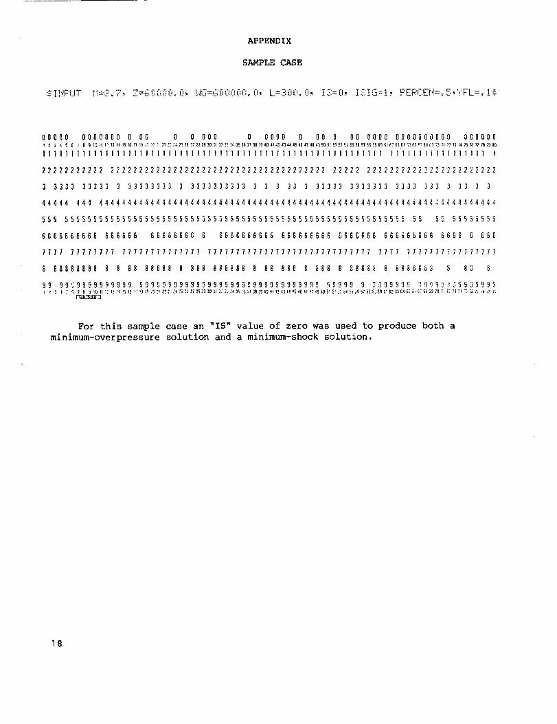
APPENDIX
SAMPLE CASE
1.2. ! :.3-- ! qZ=_d'il'il'!{'!,l'l,HI3=61.'iOOL'IO.l], I --'" "_ F,, T-;={I, •....-._, F'ERCEH=. 5, ","FL=. !_.:
00000 0000000 0l _ 3 4 _ 6 7 8 9 I_111_7311 1516
ll1111111111111i
22222222222 2222
3 3333 33333 3 3
44444 444 444444
555 555555555555
6666666666 6666G
7777 77777777 77
88888888 8 8 8
99 99S9999999999{ ? 3 I [ S 7 B _ {O ll [_13 !'l!_16
O0 0 0 000 0 0000 0 O0 0 O0 0000 0000000000 O0000017 18 13 _C _ 2? 23 _4 3_ 26 27 2_ 29 30 3; _ J3 34 35 36 37 38 3S 40 41 47 43 44 45 46 47 48 _3 EO 51 5? 53 E_ 5_ 5E 57 56 _S G_ 61 EZ 6_ 6¢ 5E E_ _7 6J _ ;_ ;I 77 73 74 7_ 75 77 78 79 80
lllllllllllllllllllllllllllllllll{llllllllll lllllllllllllllll l
2222222222222222222222222222222222 22222 22222222222222222222222
3333333 3 3333333333 3 3 3 33 3 33333 3333333 3333 333 3 33 3 3
444444444444444444444444444444444444444444444444444444444,1444444
555555555555555555555555555555555555555555555555 55 55 55555555
6 6666666G 6 6666666666 666666666 6666666 668666666 866S 6 666
777777777777 77777777777777777777777777777 7777 7777777777777777
8 88888 8 888 888888 8 88 888 8 888 8 88_38 8 8880_ _ 83 8
99999899999999999989999999999999 99999 9 _999H90 O!]_g_59Z9999I? )9 i9 ZO 21 _? _]24 _5 36 27 28Z3 10 31 IZ lJ 34 35 L5 3738 30 ¢9 E{ {243 _ a5 46 _m _3 _9 50 51 57 33 5* 5_ 3_ 57 5_ 5360 51 6_ 93 64 85 i- O? _9 3] _ 7{ 72 71 74 "3 ;3 ;3 i_ _3 30
For this sample case an "IS" value of zero was used to produce both a
minimum-overpressure solution and a minimum-shock solution.
18

APPENDIX
l--u_Ir
"9ul
,£)
o
u.io(
I--I
0tn
H
I-4
w,..9
o
LUU
Z,jj
u-<[
X..U:r
u_
"-3
a_
_ g
_ Z
N
_ Z
:1_ C3
m >-d
_ t,L
,_ uJr'J ..I
÷
C
O÷ OUJ I_
Oo _o
z
v1u_ o
x
_ U
z
I--
_ 4[,.-4 ...i
_._ c21z _
_ ,u
_ T
o4-,L,,--i,orn
0
:1%
u9
D0
..9
o
iJ 7zo
0 0 0 _
g _
o
_ _ _- ,u w
• g _ • _ o0 _ ,J I
0 0 4 _
0 0 0 _ 0÷
O • • Z
19

APPENDIX
..JuJ
000000000000000000000000000+ + ÷ + + ÷ ÷ ÷ ÷ ÷ ÷ ÷ + + ÷ + + ÷ ÷ ÷ + + ÷ + ÷ ÷÷
0000000000000000000000000 O0
oeooooeeooeeoooeooeeooooooo
(/3
,,...J
I--
I.L
_t
Z
D
tL
L_Z_.4N
Zi,=,4
Ix
u1
u..
_0000000000_ __ __ _ ____ooo0oooooooooooo0o oooooooooooo ooo ooo0oi ++++++++÷+ l I I I I I I I I I I I I I I I I I I I I I I I I I I
O_ N _ 0 _ __ _ __ _ _ ___ _
ooeeee6oeeee0e0oeeooeeeoeeoeeooeoeoeooe0
X
20

APPENDIX
el.
I.-
,-%
OOOOOOOOOOOOOoOOOOOOOOOOOOOOOOOOOOOOOOOO+÷÷÷+÷+_+++÷÷÷÷÷÷+÷÷÷+÷_+÷÷÷_÷÷÷÷++÷_÷+_
OOOOOOOOOOOOOOO OOOOOOO OOOOO OOOOO_ __ _
eoeooeoOOleOOoolooooloooeooooooooooeeoooIllllllI
e_rr,I
NNNNNNNNNNNNN_O_NNNNNNNNNNNNNN_MM_M
OOOOOOO OO OO O Oo O OO OOOOOOOOO O OO OOOO O OOO O O O÷÷ + + ÷ ÷ + ÷ ÷ ÷ ÷ + + ÷ ÷ ÷ ÷ ÷ • ÷ _ ÷ ÷ ÷ ÷ ÷ ÷ ÷ ÷ ÷ + + ÷ ÷ ÷ + + ÷ ÷ ÷
N_ _ _ _ _ _ O_N_ _N_ _ O_ _ _ _ N_O_ _ O_O _ _ _
_eleeeoeoooo_@@@@leo@ooo@@o_@@@@oooo@Io@
I I I I I I I I I I I I I I I
LU
OOOOOOOOOOOOOOOOOOO_OOOOOOOOOO_OOOOOOOOO÷÷+÷÷÷÷÷÷÷+÷÷÷÷÷÷÷÷÷÷÷÷÷÷÷÷÷÷÷+÷÷÷_÷÷÷÷÷
_N_O_N_O4_M_N_ONN?4_N__44_ON_
_ __O_NN_ _ N_ _N_N__O_O_ _
N__N__N_ _ON_ON_OOO_NNN
eooeoeeloooooeooeoelooooeeeloeeooeoelooo
I/.
OOOOOOO OO OOO OOOOOOOOO O OOOOO O OOOOO O OOOOOOI I I I I I I I I I I I I I I I I I I I I I I I I I I I I I I I I I I I I I I I
IIIIIIll
X
OOOOOOOOOOOO OOOOOOOOOOOOOOOOOOOOOOOOOOO O÷ ÷ ÷ ÷ + ÷ ÷ ÷ ÷ ÷ ÷ _ ÷ _ ÷ ÷ ÷ ÷ ÷ ÷ _ ÷ ÷ ÷ ÷ ÷ ÷ ÷ + _ ÷ _ _ ÷ ÷ ÷ ÷ _ ÷ ÷
O__ON_ _N_ _O_ _ O_ _ __ _
__ ___OO O_NNN_ ___ __
_H___NNNNNNNNNNNNNNNNNNNNNNNNNNoooleollelOleeeooolooeeoeeeeeeeeeeeee@@ @
21

APPEND I X
,,%
.J
u_0
O OO O O O O:O O O O O O O O O O OO O O O O OO O O O OO O OO O O O OO OO÷ ÷ ÷ ÷ ÷ ÷ + ÷÷ ÷ ÷ ÷ ÷ ÷ ÷ ÷ ÷ ÷ ÷ ÷ ÷ ÷ ÷ ÷ ÷ ÷ ÷ ÷ ÷ ÷ ÷ ÷ _ +÷ ÷ ÷ ÷ ÷ ÷
________O_O_O_O_
_________O_O
_ _ _ _ __ _ _ O_ O_ _O_ _ _ _ _O _ _ _
eoee_oeooooooooo_eooeeooeoeeeeooooeoeeeeI I I I I I I I I I I I I I i I I I I i I I i t 1 I I I I I I I I I I I I I I I
C_
I
OOOOO O OOOOOOOOOO OOOOOOOOOOOOOOOOO OOOOOOO÷ ÷ ÷ + _ ÷ + ÷ ÷ ÷ ÷ + ÷ + ÷ ÷ + ÷ ÷ ÷ ÷ ÷ + ÷ + + ÷ ÷ ÷ ÷ • ÷ ÷ ÷÷ • ÷ + ÷ ÷
_ _ __ _OO_N___H_NO__ _O_
_ __O_ _ _O_N_H_O__OO_ _ _OOO_
oooooooooeeooooooeolooloooeeooooooooeooo
IJJ
000000000000000000000+ + ÷ ÷ ÷ + ÷ ÷ ÷ ÷ • + ÷ + ÷ ÷ +÷ ÷ ÷ ÷
O_ _ _ _ _ O_ _ _0_
_ _ _0_ O_ _ _ _ _ _N_ _
e_oo_ee_looooloeoooel
LL
22

APPENDIX
ou
-.Jw
____0000000000000000000000000000
0000000000000000000000000000000000000000÷÷÷÷÷÷÷÷_÷÷÷÷÷÷÷÷÷÷÷÷÷÷÷+÷÷÷÷÷÷÷_+÷÷÷÷÷_
I I I I I I I I I I I I I I I I I I I I I I I I I I I I I I I I I I I I I I I I
I
liJ
0000000000000000000000000000000000000000I I I I I I I I I I I I I I I I I I I I I I I t I I I I I I I I I I I I I I I I
_ _ __ N__O0_ _ _ _0 _ _0 _ O_ _0_0 _
_ _ _ _ _ _00_ _ _ _ _ _ _0 _ _ _ _ _ _ _ _ _ _ _ _O_ _ _ _ _ 0 _ _ _ _ _ 0 _ _ _ _ _ _ _ _ _ _ _ 0,_ O_ 0
_ _ _0_ _ _0_ _ 0 _ _ _ _ O_ _ _ _ _ _ _ _ 00_ _
x
23

APPENDIX
o.
k--.JuJ
(5
O OOOOO OOOOOOOOOOOOOO OOOOOOOOOOOOOOOOOOOOOO÷_÷÷÷+÷÷÷÷÷÷÷÷++÷÷÷÷÷
O__ _O O__ _ _O
_ OO _ O_ O_O_ _ _ O_ __ _ _O _ _ _ _ N_ N_ _ O_ _
OOO_____ooooooooooo oooooooo+++ I I I I t I I I I I I t I I I I
_ O_ _ _ _ _ N_ _ _N _O
_ _ _ _ O_ N_ N _ _ _ _ _ __ _ _ _N_ONN_ N_N _N_
_NO __ _ _ _ N_ _ _ _
Ix
OOOOOO OOOOOOOOOOOO OOOOOOOOOOOOOOOOOOOOOO+ ÷ + ÷ ÷ + ÷ ÷ + + + ÷ ÷ ÷ + ÷ ÷ ÷ ÷ + + ÷ ÷ ÷ ÷ + ÷ ++ ÷ + ÷ _ ÷ ÷ ÷ +÷ + ÷
O_N _O _N_ _ _ _ _ _N NN_ H_ _O_N_N_O_ _ _ _
_NNNN___N_O__OO_NN_
oooeoeeeeooeoeoeeooeoeoooeooooooooeoooeo
LAJ
LL
_____NNNNNNNNNNNNNNNNNNNNN
OOOOOOoOOOOOOoOOOOOOOOOOOOOOOOOOOOOOOOOOI I I I I 1 I I I I I I I I I I I I I I I I I I I I I I I I I I I I I I I I I I
NN_O_?_3_NMNN?_OM_ONM?OMNM@_M_@N_N_ON
_ _ _ _ N_ _N _ _ _ _O _O _ _ N_N _ N_ _O_ _NN_
_____O_OO_O_N_O_N_O_________NNNNNNN_
24

APPENDIX
(DO
I Io. u_uu
co,o•,_ o4oJ
-J ,0,-4
,'% _
4" -,1"OO
+ 4"
I:K O('¢_
I e'J ,IDX ,_ 4"
,,-4 _
I.U
r_NOO
I !t_ IJI
I1 '4" ,13r-- ,13,-4,-4
OO
4. 4-LU
,-404,O_
:,( aOCO
,--4U_
O,'_OO
6404
25

APPENDIX
N
O.
NNNNNNNNNNNNNNNNNNNNNNNNNNNNNNNNNNNNNNN
NNNNNNNNNNNNNNNNNNNNNNNNNNNNNNNNNNNNNNN
000000000000000000000000000000000000000
u_
O_
p--
*I
Z
I_9
ill
LU
0
0
0
0
J
IX
26

APPENDIX
o_
0-
000 000000 O000 O0 O0 000 _ _ _ _ _ _ _ _ _ _ _ _
oooooooooooooooooooooomeoeeoooe4eooeooee
I l l l I l l I l l I I I l I I I l I l
Ix
27

APPENDIX
cL
Ix
I
28

APPENDIX
Q.
[D
_D
u_
tJU{/% _-.
3Ee
,-4
[D
u%
_uJu
xz
1-q
÷ •,/J uJ o _,-_ o
a_
ix/ • • u •
_,4 | P_- _ dg rn
[21
.-J ..J _-- L.) _ _.
29

APPENDIX
I"4
,-I0u_
I
ow
v_
ul
v-
IE:
_ N
g _w _
_ eIE
Q
O
r_
i!
40"-7"ur%
U_Un_-4
_ go
-4 I
o o 4- _ ,-t . _o
r_ _ _m _
I--
_iJ :_- j _ o.. • i,u
t_ ..J
_ o o _ o _o _ _ _ _
o 0
,_ 0 _ _
(23
u_
I.- x:
I.- _ F-
uJ
r'l
_J
z
Q
o
_4
0
2-
.el
1
:)
_ ÷ uuuJ .u tu uJ ,-d J_ o
,_ m 0 r,. 0_ 0 0
u_ o _ ,-4 o • o, :,%u. _n ,-_ u_ ,-d 4- •
!t,Jr,J,-4o4-
r--o,-o
o
!
÷
o,o o-_n
g 2
,.y.
• ,,
u. | _I-
_,tu
3O
APPENDIX
I--
-.I
LU
C3
0_______
000000000000000000000000000
+ ÷ ÷ + ÷ ÷ ÷ ÷ ÷ ÷ ÷ ÷ ÷ ÷ ÷ ÷ ÷ ÷ ÷ ÷ ÷ ÷ ÷ ÷ ÷ ÷ ÷
_'____ ___
oeoeoeeeoloooeoeooeoeoeeeue
U'I
LU
...J
QD
I--
LIJ
a,,
CD
Z
LL.
<9
Z
N
,-.4
Z
:E
n.-
0O
IX
tLI
IJI.
OOO_OOOOOOOOOOOO_OOOOOOOOOO_OOOOOOOOOO
÷÷÷÷÷÷÷÷÷÷÷÷_÷÷÷÷÷÷÷÷÷÷÷+÷÷÷÷÷÷÷÷÷÷÷÷÷
_ _ _ _ _ _ _ _ _'_O_ _ _ _ _ _ O_ _ _ __ __ _ _
Illlllllllllllllltllllllllllltliliillt
0
_OOOOOOOOO________
OOOOOOOOOOOOOOOOOOOOOOOOOOOOOOOOO.OOOOO
I ÷ ÷ ÷÷ ÷ ÷ ÷ ÷ ÷ I I I I I I I I I I I I I I I I I I I I I O I I I I I I
_O_NO__O_O___N___
O O_ O_ O_ _ _N _ _ _ _ _ _ _ _ _ _ OO _ _ _ ? _
_ _ __ _ _ _ _ _ _'_ _ _ _ _ _ _ _ _ _ _ _ _
oleeloeeooooOooOOoool_eeoooooeleolooeo
0
_NNNNNNNNNNNNNNNNNNNNNNNNNNN_QQQQ_
OOO OOOOO _OoOOOOOOO OOOOOOO OOOO O OOOOOO _O
÷÷÷÷÷÷÷÷÷÷÷÷÷÷÷÷÷÷÷÷÷÷÷÷÷÷÷÷÷÷÷÷÷÷@÷÷÷
oooeoooeooeooooeeooooooeeooooeoeoooooe
3]

APPENDIX
Q.
.J
LU
OOOOOOOOOOOOOOOOOOOOOOOOOOOOOOOOOOOOOOOO÷ ÷ ÷ ÷ ÷ ÷ ÷÷ ÷ ÷÷ ÷ ÷ ÷ ÷ ÷ ÷ ÷ ÷ ÷ ÷ ÷ ÷ ÷ ÷ ÷ ÷ ÷ ÷ ÷ + + ÷ ÷ ÷ ÷ ÷÷ ÷ ÷
_O_N_ _ O_N_O_O_N_ ___NNN_OO_ __ _ _ _ _NN_OO_ _ _O_O_O_O
.... ....
!X
_M_MMNNNNNNNNNNNNNNNNNNNNNNNNNNNMM_MMMM_OO OOOOOOOOOOO OOOOOOOOOOOOO OOOOOO OOOOOOOO÷ + ÷ ÷ ÷ ÷ _ ÷ ÷ ÷ ÷ ÷ ÷ ÷ ÷ ÷ ÷ ÷ ÷ ÷ ÷ ÷ • • • ÷ ÷ ÷ ÷ ÷ _ ÷ ÷ ÷ ÷ _ ÷ ÷ ÷ ÷
_,_¢_N_O_@_N_O__¢N_O_['_¢N_O_
__O_N_¢__O_N_¢__O_N_O_N_¢_
OOOOO_NO@_NO_N_M_N_M_@_NO_NNNNNNN
I I I I I I I l I I I I I I I I I I I I I I I I I I I I I I I I
ULI
OO OOOOOOOO OOOOOOOOOOOOOOOOOOOOOO 0OOOOO OOI I I I I I I I I I i I I I I I I I I I I I I I I I I I I I I I I I I I I I I I
_N__ _ O _O _N_N_ _ _ _ _O___O_N_ _ _ON_ _O _ &_ _O__ _N_ON _O_ _ _
_ _ &_O_O_ O_ _N_N_N _N_ __ NO_O_ _
. . . . ........... . ........ • ...... " _ _ ; _ _ _ _ _
32

APPENDIX
.f
..Jtu
OOOOOOOOOOOOOOOOOOOOOOOOOOOOOOOOOOOOOOOO÷÷+÷++÷÷÷÷+÷÷÷÷÷÷÷÷÷+÷÷+÷++÷_÷÷÷++÷÷÷÷÷÷
NNNNNNNNNNNNNNNNNNNNN_M_NNNNNNNNNNNNNNN
c,,
I>(
OOOOOOOOOOOOOOOOOOOOOOOOOOOOOOOOOOOOOO O O• ÷ ÷ ÷ ÷ ÷ ÷ + ÷ + + ÷ + ÷ + ÷ ÷ ÷+ + ÷ + ÷ ÷ ÷ + ÷ + ÷ ++ _ + + • ÷ ÷ ÷ ÷ ÷
_O__NO__N_ _O_N_N_ __ _O_ _ _ __ _O__ _O_N_O_O_ _ __ _ N
NNNNN____ _O_N_ _N__ _
oeeooeoooooooeeeooeooooooeoooooooeooooel
1.1,1
4_.el[
OOO OOOOOOOOOOOO OOOO OO
÷ ÷ ÷ + + ÷ + + + + + + ÷ + ÷ + ÷ + + + +
_@N_O¢@N_N_,__
oo@o@_oeooooo@looe@@@
LI.
______0000000000000__ooooooooooooooooooooooooooooooooooooooooI I I I I I I I I I I I I I I I I I I I I + ÷ ÷ + + ÷ ÷ ÷÷ ÷ ÷ + ÷ I I I I I I
X
OOOOOOOOOOOOOOOOOOOOOOOOOOOOOOOOOOOOOOOO
_?O_N_M_M_N_?O00OO000000000000000
____ __ 0000000000000 __
eeeeeeeeooloooooeoe@eelleleeeeeeeeleeeee
33
APPENDIX
-J
uu
____0000000000000000000000000000
0000000000000000000000000000000000000000+ ÷ ÷ ÷ + ÷ + • @ ÷ ÷ + ÷ ÷ ÷ ÷ ÷ ÷ ÷ ÷ + ÷ ÷ ÷ + + ÷ + ++ ÷ ÷ ÷ ÷ + + ÷ + + +
__ __ _ _0_0_0___ _ __0 _ __ _ _ 0 _ _ _ _ _ _ _ _ O_ 0 _ 0 _ _ _0 _ _ _ _0_ _
_ 0 _ 0_ _ _ O_ _ _ _ _ _ _0__ _ _ _ _ _ _ __ _ _ _ _0_ _ 0 _0 _ _ _ _ _ _ _ _ _ _ _ _ _ _ _
;;;;;;;;;;;(;;;;;;;;;;;;;;;;;;;;;;;;;;;;
!x
0000000000000000000000000000000000000000
++ + + ÷ + + ÷ ÷ ÷ ÷ ÷ ÷ ÷ ÷ ÷ ÷ + ÷ ÷ + ÷ ++ ÷ ÷ + • ÷+ ÷ + • ÷ ÷+ @ ÷ @ ÷
_0_0__00_ __ __0_ O0 ___0
_ _ _ _ 0_ _ _ _ _ _ _ O_ _ _ _ _ _
_ O_ _ __000_ _ _ __ _ _O00C 0
eoeeoeooooeoo_eooo_oo6_eo_eooo_ooeoee
tu
ul.
)<
34

APPENDIX
Q.
J-..J
UJO
0 O0000000000000000000000_____0000000000000000000000000000000000000000+ ÷+ +÷ + ÷ + + + + ÷ + + ÷ ÷ ÷ ÷ ++ ÷ + ÷ ÷ I I I I I t I I I I I I I I I i
_ __ O_ _ _N__ _ _ _ _ _ _ _ _
_ _ _ _ _ _0_ _ _ __ 00_0_0_0 _ _ __ _
___00_ ______0_ _
!x
0000000000000000000000000000000000000000÷ ÷ ÷ ÷ ÷ ÷ ÷ ÷ ÷ ÷ ÷ ÷ _ ÷ ÷ ÷ ÷ _ ÷ ÷ ÷ ÷ _ ÷ ÷ ÷ ÷ ÷ _ ÷ ÷ ÷ ÷ ÷ ÷ ÷ + ÷ ÷ ÷
_ _ _ _0_ O_ _iO _ _ _ _ _ _ _ _00_ _ _ _ _ _ _ ____0__00_0____00
U
00000000000000000000000000ooo00o_00000o
I I I I I I I I I I I I I I I I I I I I ! I I I I I I I I I I I I I I I I I I I
_ _ _0_ _ _ _ _ _ _ _ _ _ _ _ _ _ _ 0 _ _ _ _ _ _ ______¢______0_
_ _ _ _ _ _ _ _ _ _ _ _ _ _ _ _ _ _ _ _ _ _0 _ _ _ _ _ _
::::::::::::::::::::::::::::::::::::::::::::
x
35

o.
-JU_
Ix
w
LL
X
36
OOI I
wu_;u'_ ,,a"
0 L£"ir_, ,i,,,,4r,r%,rq
O0÷ ÷
t.ul_u'_ff%
,-4,..-4
N ('_,10 0
I !uJ u
O0.41- .4-
O0 _OCO
4" 4"
0OO
APPENDIX
APPENDIX
('4o_
uU
O_
0
Z 0(.9 0
v_ --I •
o. 0UU
3:
U_
O.
el5!
_<
37

APPENDIX
(%J
0.
IX
38
APPENDIX
OGCL
_ _ _N_NN _ _N _ _ OO OO O O O O O OO O OO O OOO
:::::::::::::::::::::::::::::::::::IIIIIIII
!
,0e_j
--4!
39

APPENDIX
4O

REFERENCES
I. Jones, L. B.: Lower Bounds for Sonic Bangs. J. Roy. Aeronaut. Soc.,
vol. 65, no. 606, June 196], pp. 433-436.
2. Jones, L. B.: Lower Bounds for Sonic Bangs in the Far Field. Aeronaut.
Q., vol. XVIII, pt. I, Feb. 1967, pp. 1-21.
3. Seebass, R.: Minimum Sonic Boom Shock Strengths and Overpressures. Nature,
vol. 221, no. 5181, Feb. 15, 1969, pp. 651-653.
4. George, A. R.: Lower Bounds for Sonic Booms in the Midfield. AIAA J.,
vol. 7, no. 8, Aug. 1969, pp. 1542-1545.
5. George, A. R.; and Seebass, R.:
Both Front and Rear Shocks.
pp. 2091-2903.
Sonic Boom Minimization Including
AIAA J., vol. 9, no. 10, Oct. ]971,
6. Seebass, R.; and George, A. R.: Sonic-Boom Minimization. J. Acoust. Soc.
America, vol. 51, no. 2 (pt. 3), Feb. 1972, pp. 686-694.
7. Darden, Christine M.: Minimization of Sonic-Boom Parameters in Real and
Isothermal Atmospheres. NASA TN D-7842, 1975.
8. Whitham, G. B.: The Flow Pattern of a Supersonic Projectile. Commun.
Pure & Appl. Math., vol. V, no. 3, Aug. ]952, pp. 30]-348.
9. Walkden, F.: The Shock Pattern of a Wing-Body Combination, Far From the
Flight Path. Aeronaut. Q., vol. IX, pt. 2, May ]958, pp. ]64-]94.
10. Hayes, Wallace D.: Linearized Supersonic Flow. Ph.D. Thesis, California
Inst. Technol., ]947.
II. Lung, Joseph Lui: A Computer Program for the Design of Supersonic Aircraft
To Minimize Their Sonic Boom. M.S. Thesis, Cornell Univ., ]975.
12. Marconi, Frank; Salas, Manuel; and Yaeger, Larry: Development of a Computer
Code for Calculating the Steady Super/Hypersonic Inviscid Flow Around Real
Configurations. Volume I - Computational Technique. NASA CR-2675, ]976.
41
I!
!II
Ae IEquivalent areadistribution
Y A"
1 S e 1120 (Y-C)
F-function
d_
Ap
Ap
t Balance areasfor shocklocation
Theoretical pressuresignature
(multivalued)
Predicted pressuresignature
Figure I.- Sonic-boom prediction methods.
42

Near field
Mid field
Far field
Figure 2.- Pressure-signature propagation.
43

44
G)
(n0
e-
h.
e"
V)
cn
0e.,
e"
m <]
E00
..C
_3
E0 00 _-
..Q "10
0 _
._1 _-
0
C_
!.c
-,-I
.c
I
I
.r,,I
F
Ap
A e
L
' Slope B-Slop
SI I I
0 l
Axial distance
Figure 4.- Illustration of the theoretical concepts of near-field sonic boom.
45

-_:!_t--.-H / =_-
LI_ LI !- i4J .....
_-..l= ....._ :--
:4+:---_:ii
bH"q :i-_-- 0
T-71-
_--e t---
-! w!-
r, t 2 :
::Nq-i
<
00
0
o
0
4a
°_-1
I,Mo
g
0
°_
I
1.4
.i..-I
I I
46
o0.¢;
E
Er-
_n6)
o
E
Eo
N
_d
_
I_" ¢0 --
CO _" O-- O OO O O
0
.,4.IJ
t_o,--I
t..I0
N
_), _t- _ _)0
O --
,. _) o)
--_o --. _ •
L I I -0 0_I CO
0 0o o
_J
_n.,--i4J"O
.,-I U},_ u_
,..4
I
_0
.,M
47
0 s_
o
_N
_°"_ o°
0 II
_ 0 "2,
u. ,_ 0i! i
o _ol2
48

E"E
| I I I --
q
0I!
_ Lo. o<1 ""
wL..2_
I,.
0
E2_
Ee-
I
m
m
I I J
N -- 0
<1
0I!
L_
o
0q
0q
_ 00_ o3
0II
0
,f,Lo 0
0II
r_o
I
co
m
0
n
l- 0
O3
0
N
r"
I
0.-4
0
0
U;
0
0
_n
00
.,-I
00
0
I
o,-_
0
v
p-
II
000
0O_0
u_
C_
II
q_
000
O0O0c_
_0
II
e_
dII
49
[O
1O
5O
IO
I I 1
..Q
OC:l04
C)00
O_D
1OoO
IOO4
I I I
O
r--
OOJ
oo
IOCO
E
O
14:1
O1.oi.o
O-- i_o
OI.,O00
O
Q,-4
OOO
OOI,,ID
..M
l.¢)I.¢'1
O,1
II
i I_ II
4.1 Cl
P
t..i (_1
t..i.,,-I
0 II
-r,4
[/1
m
0.1
1.4
I
t_


1. Report No. 2. Government Accession No. 3. Recipient's Catalo_j No.
NASA TP-1348
5, Report Date
January 19794. Titleand Subtitle
SONIC-BOOM MINIMIZATION WITH NOSE-BLUNTNESS RELAXATION
7. Author(s)
christine M. Darden
9, PerformingOrganizationNameand Addre_
NASA Langley Research Center
Hampton, VA 23665
12. Sponsoring Agency Name and Address
National Aeronautics and Space Administration
Washington, DC 20546
6. Performing Organization Code
8. Performing Organization Re_rt No,
L-12464
10, Work Unit No.
505-09-23-11
"11, Contract or Grant No.
13. Type of Report and Period Covered
Technical Paper
14. SponsoringAgency Code
15. Supplementary Notes
16, Abstract
A procedure which provides sonic-boom-minimizing equivalent area distributions
for supersonic cruise conditions is described. This work extends previous
analyses to permit relaxation of the extreme bluntness required by conventional
low-boom shapes and includes propagation in a real atmosphere. The procedure
provides area distributions which minimize either shock strength or overpressure.
17, Key Words (Suggested by Author(s))
Sonic-boom minimization
Impulse
Pressure signature
Equivalent area
19. S_ur;ty Cla_if. (of this report)
Unclassified
18. DistributionStatement
Unclassified - unlimited
J
20. S_urityClassif.(ofthis _ge} 21, No, of Pages
Unclassified 50
Subject Category 02
' For sale by the National Technical Information Service, Sprin£field, Virginia 2216]NASA-Langley, 1979