solving the plumbing puzzle - dewtec · solving the plumbing puzzle 109 technical section -...
TRANSCRIPT
Automotive Plumbing is like a jigsaw puzzle, lots of bits andpieces all looking much the same and no real guide as towhere they go.
The Earl’s® catalog shows you the bits and pieces. The follow-ing notes will help novice plumbers to sort out which ones touse and hopefully provide a start to developing skills which willmake more advanced plumbing a lot easier when you cometo it.TOOLS YOU WILL NEEDBasic plumbing requires:• Vice with soft jaws to avoid marking aluminum
fittings - available from Earl’s® (P/N 004ERL and 005ERL - page 101)
• Fine bladed hacksaw, angle grinder or chop saw - for cutting hose.
• Set of wrenches. NOTE: Aluminum wrenches which reduce marking of aluminum adapters and hose ends are available from Earl’s. (Page 99)
• Ruler - or preferably Vernier gauge - for measuring hose and barb fitting diameters.
• Tape measure- minimum extended length 10ft (3m) for measuring hose and hose run lengths.
• Length of string or thin wire - to assist in measuring lengths of existing or planned hoses.
• Screwdrivers - flat blade type.• Good straight Tin Snips - recommended for cutting
and trimming TUBE-BRAID™ sleeves.• Duct Tape or similar to wrap hose - prior to cutting.
(ALWAYS wrap to prevent fraying).• Earl’s® Assembly lube (P/N 184004ERL - page 102),
Sewing machine oil or clean engine oil - used on hose endthreads before assembling ends to hose.
If you intend to assemble Speed-Flex™ brake lines in sizes 3or 4 with reusable Speed-Seal™ hose ends you will need aEarl’s® braid spreader (P/N 007ERL - page 98) and a utilityknife.
THE MOST IMPORTANT BASIC CONCEPTS1. Hose diameter. The inside diameter of an original hose ismost important - it is this which determines what sizes of stain-less braided hose you will use to replace it. The outer diame-ter is only of use when determining which size of Earl’s®Tube-Braid™ Sleeve or Flame Guard or Econ-O-Fit™ to applyif covering the old hose rather than replacing it.
2. Hose sizes. You will find each type in the Earl’s® cataloghas a size number - 4,5,6 etc. Nearly all the hose ends andadapters also have a size number. For each size, there is awhole family of parts whose part number usually ends in thesize number to go with the size of hose. A hose end of 6 willfit the hose size 6. For example: Auto-Flex™ hose 300006ERLworks with Auto-Fit™ hose ends 300106ERL, 309106ERL, etc.and adapters 981666ERL, 982206ERL, etc. And such parts asin-line filter 230106ERL.
3. Thread sizes. The Earl’s® catalog provides outlines of themost common NPT and AN threads on pg. 111. If in completedoubt, a thread gauge may be useful to you. Metric threadedadapters to convert from metric holes to AN hose end threadsare shown in the Earl’s® catalog as well.
BASIC STREET MACHINE PLUMBINGYou will be looking most often at the following product types:Auto-Flex™ and Pro-Lite 350™ hoses, Tube-Braid™ stainlesssteel sleeving, Econ-O-Fit™ clamps, Auto-Fit™ and SwivelSeal™ hose ends, fuel line kits, pipe thread to AN adaptersand carburetor/power steering/fuel pump adapters.
1. Radiator hoses. Due to their often complex curvature andwide range of sizes pre-braided Auto-Flex™ or Perform-O-Flex™ hose usually cannot be used . Instead we recommendthe use of Earl’s® Tube-Braid™ sleeve (Page 104) or Form-A-Flex™ radiator hose (Page 59).
2. Heater hoses. These may be covered with Tube-Braid™ sleeve, but should preferably be replaced with Auto-Flex™hose as over a long length its pre-braided cover looks muchbetter! Usually sizes 10 or 12 is suitable. Measure either theinside diameter of the hose you are replacing or the outsidediameter of the barb that the old hose pushed over and this willtell you what size of hose to use. Size 12 hose (11/16”) willclamp down OK onto 5/8” barbs. Fix in place with Econ-O-Fit™ hose ends of the correct size for the hose or for the oldhose + sleeve + tape. Usually sizes 10 or12 for proper braid-ed hose, size 14 if you used Tube-Braid™ sleeves.
3. Fuel lines. Normally you will do these using size 5,6,7 or 8Pre-braided hose or Pro-Lite 350™ hose to replace the origi-nal hose, and appropriate hose ends or Econ-O-Fit™ hoseclamps.
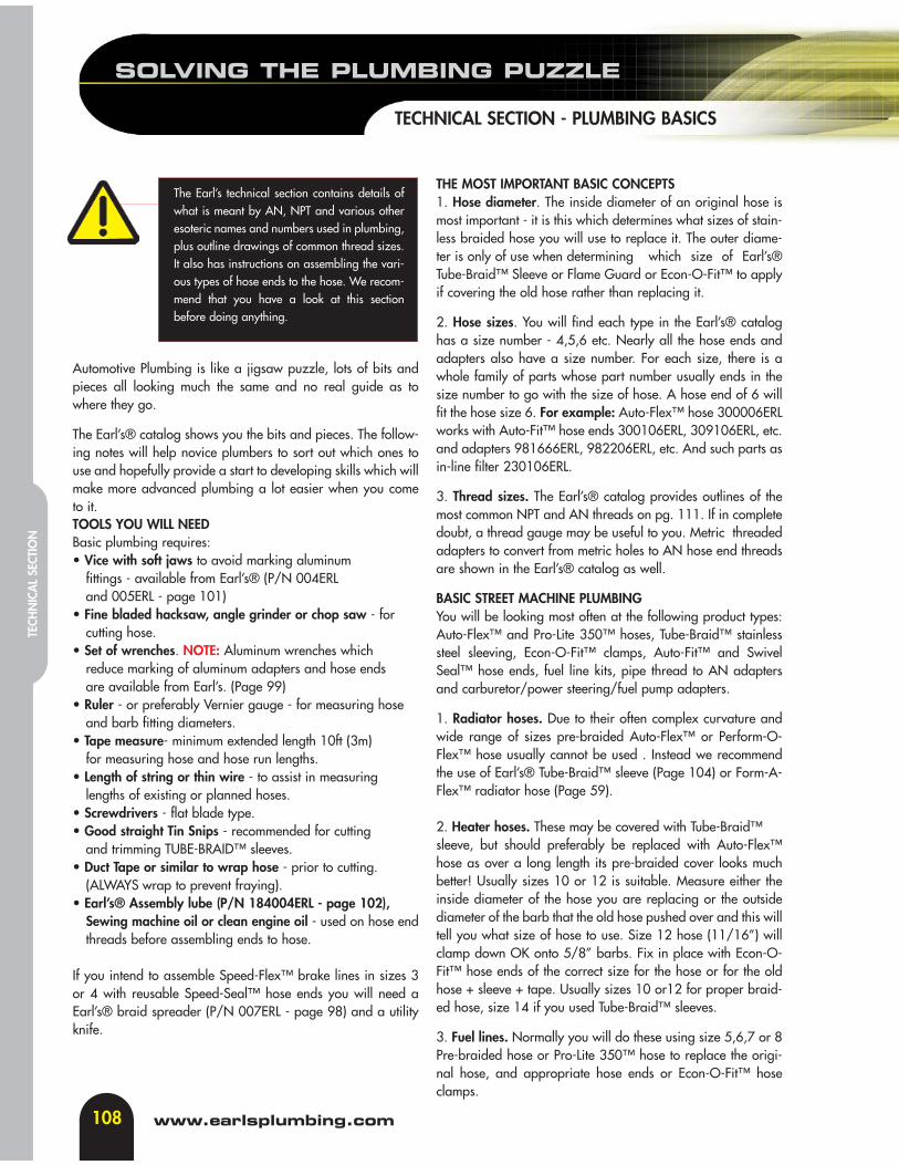
The Earl’s technical section contains details ofwhat is meant by AN, NPT and various otheresoteric names and numbers used in plumbing,plus outline drawings of common thread sizes.It also has instructions on assembling the vari-ous types of hose ends to the hose. We recom-mend that you have a look at this sectionbefore doing anything.
108
SOLVING THE PLUMBING PUZZLE
TECHNICAL SECTION - PLUMBING BASICS
www.earlsplumbing.com
TECH
NIC
AL
SECT
ION
SOLVING THE PLUMBING PUZZLE
109
TECHNICAL SECTION - PLUMBING BASICS
tech line: 310-609-1602
TECHN
ICAL SECTIO
N
4. If you have replaced your carburetor with, lets say, aHolley® carburetor, and a Holley® regulator, you will need tolook at going to a complete AN replacement for your plumb-ing system. Hose ends, hose, adapters and a fuel kit of theappropriate sizes.
5. Other hoses. There may be other hoses, breathers, over-flows, etc. that you want to replace with Earl’s® stainless braid-ed hose and fittings. Just measure internal diameter and lengthand select the appropriate hose, hose ends or Econ-O-Fit™clamps to suit.
6. Oil & Transmission coolers. If you want to fit an engine ortransmission cooler to your vehicle, first work out where youwant to put it and determine the space available. Select a cool-er from Earl’s® extensive range of Temp-A-Cure™ coolers(Page 62). Then the right sandwich adapter to enable you toplumb the cooler to the vehicle. Oil coolers generally use size10 hose and hose ends and pipe thread to AN adapters.Transmission coolers generally use size 6 or 8 to plumb thecooler.
7. A table with suggested engine oil cooler sizes follows. Notethat climactic conditions, degree of engine tune and modifica-tions etc. may mean the suggested cooler is not to be the exactone you need - consult your dealer orEarl’s® tech line 1-310-609-1602.
ENGINE SIZE COOLER NO.1000-1500 cc 41310ERL1501-2500 cc 41610ERL2501-4000 cc 41910ERL4001-5000 cc 42510ERL5001-6000 cc 43410ERL
MOST IMPORTANT OF ALL...Don’t despair if you don’t get it all, or don’t get it all right thefirst time around. If your dealer is conveniently close, don’t buyeverything at once. Get a little at a time until you gain confi-dence. And if you bought something that doesn’t fit, the deal-er may, although he is under no obligation to do so, take itback in part exchange for what you really needed all along,as long as you haven’t damaged or marked the part you did-n’t want!
BRAKE HOSESThese days road-going vehicles in most countries have to haveflexible brake hoses complying with various rules and regula-tions. So if your vehicle is street registered, we suggest you useEarl’s Hyperfirm™ street legal hoses.
If your vehicle does not have to comply with such regulations,Earl’s® huge range of reusable Speed-Seal™ hose ends forSpeed-Flex™ Teflon™ hose will let you do pretty much any-thing. For adapters to suit most brake system components,check out steel brake hydraulic adapters. We strongly suggestyou use sizes 2 or 3 Speed-Flex™ for brakes and size 4Speed-Flex™ for clutch hoses.
ONLY use Earl’s® Speed-Flex™ Teflon™ hose for brakes andclutches. Other types of Earl’s® hose are totally unsuited to thebrake and clutch application and may cause accidents leadingto injury or death.
RACE CAR AND SPEED BOAT PLUMBINGMechanics plumbing high performance competition vehiclesand boats will usually have considerable experience in the useof stainless braided and other hoses, so here are only a fewgeneral notes too follow.
1. Hose to use. We suggest Earl’s® Perform-O-Flex™ hose toprovide the ultimate in reliability for almost all your needs.. Ifthe chemicals in some modern fuels and lubricants cause aproblem, sometimes shown by a smell of petrol, consider usingTeflon® lined Speed-flex™ hose. Where ease of use, reducedweight and low pressure are a consideration, Earl’s® SuperStock™ & Pro-Lite 350™ hose may be suitable. For high endplumbing requirements use our premium smooth boreTeflon™/Kevlar™ covered Ultra-Flex 650™ hose.
2. Hose ends to use. With Perform-O-Flex™ hose use Swivel-Seal™ or Auto-Fit™ hose ends. Super Stock™ hose endsshould be used with Super Stock™ hose. Speed-Seal™ hoseends must be used with Speed-Flex™ hose. Pro-Lite 350™hoses uses Swivel-Seal™, Auto-Fit™ or Auto-crimp™ hoseends. Ultra-Flex 650™ hose must use Ultra-Flex hose ends.
3. Adapters to use. The Earl’s® catalog list a range ofadapters suited to all Earl’s® hose ends. Where lack of spacemake life awkward, consider using the special Swivel-Seal™hose ends which have adapters built into them. Dry sumppumps and similar pumps usually work best with Earl’s® Portadapters in them. Note that when using NPT pipe threadadapters you should apply Teflon® tape or pipe sealant,Loctite 567 or similar products to the tapered threads beforewrenching them up.

110
ENGINE INSTALLATION
TECHNICAL SECTION
www.earlsplumbing.com
TECH
NIC
AL
SECT
ION
INSTALLATIONWhile Earl’s hose and hose ends make a pretty fool-proof com-bination, there are a few general rules to follow to make surethat you end up with a sanitary and trouble-free installation:
1. Make sure that there is adequate clearance between thehose ends and anything that they might be able to contact.While the hose is flexible, the hose ends are not!
2. Do not allow the hose to contact a sharp corner, nut, bolt,rivet stem or anything else that might cause damage. Atany point where a hose passes through a panel, install agrommet for chafe protection.
3. Do not allow the hose to rub against anything—even if thesurface on which it rubs is flat. The stainless steel braid isa very efficient low speed file and will abrade throughanything that it moves against. In order to prevent chafingand to keep your hoses where you meant for them too besupport the hoses every 18" or so with either a cushionclamp or a ty-wrap.
4. Do not force the hose into too tight a bend. Follow theminimum bend radius chart. Do not kink the hose, eitherby too tight a bend, by misalignment between the hoseend and the part or adapter on short assemblies or bygetting the whole assembly into a helix on long assem-blies. Align the hose end with the adapters so that thehose is not placing strain on the hose end or on theadapter. The SWIVEL-SEAL design reduces these prob-lems, but only care in installation will eliminate them. Wemanufacture enough hose end and adapter configura-tions to allow a sanitary and sound solution to just aboutany installation problem.
5. Keep the hoses as far away from extreme heat sources (liketurbochargers and exhaust systems) as possible. If you mustrun close to such things, use an air gap insulating paneland/or fire resistant Flame Guard (pg 104) sheathing. Donot run fuel lines in proximity to hot fluid lines (or anythinghot) or you will end up with either hot fuel and low power orvapor lock. Do not run hot fluid lines near cool fluid lines ornear to the driver.
6. Do not over-tighten the hose ends onto the adapter fittingsor parts. The seal is achieved by the design of the matingsurfaces—not by muscle. It helps a lot to use the wrench-es made for the job. (See page 99)
MAINTENANCEVirtually no maintenance is required. Basically, maintainingEarl’s high performance plumbing hose ends is a question ofpreventing abuse.
1. Inspect the plumbing installation frequently for signs ofchafing, abrasion, kinking, crushing or seepage.
2. Take care not to crush, stretch, kink or otherwise damagethe hose assemblies when changing engines etc.
3. Keep both hoses and fittings CLEAN.(a) Before removing any hose end from its adapter or port,
wash the assembly down with solvent—or even gaso-line—and blow it clean and dry so that no grit can findit’s way into the threads or the sealing surfaces.
(b) As soon as the hose end has been removed, install aCLEAN protective plug into the hose end and a CLEANcap onto the adapter. This will keep dirt out of the linesand the fittings and will keep the fluid off the floor, themachine and the mechanic.
(c) Always inspect both hose ends and adapters for dirtbefore reassembly.
(d) Correctly assembled Earl’s hose ends will not leak ifthey, and the adapters are undamaged, clean andproperly tightened. The only way to be certain thatevery hose end is properly tightened is to form thehabit of NEVER leaving the adapter, a hose end (oranything else) loose, finger tight or partially tightened.Even when you know that you are going to take thething right off again, correctly tighten it—every time.
LEAKSIf it leaks, it has probably been assembled incorrectly or thesealing surfaces on the adapter and the nipple have beendamaged—or just possibly someone has attempted to assem-ble an AN 37° seat hose end into a 45° SAE cone. Damage tothe cone or the seat can be caused by a multitude of sins—dirtand over-tightening being the most common.
RE-USEAll of Earl’s removable hose ends are completely reusable as isthe hose and as are most of the competing brands. As usual,Earl’s has an edge. When disassembling a nipple and cutter typehose end, it is very common for the inner tube of the liner, whichis captured between the nipple and cutter, to be torn off and toremain in place. If this happens, the rubber must be removedbefore the hose end can be reused—and it is a bear to get out.With SWIVEL-SEAL the chances of this happening are greatlydiminished because the cutter can rotate with respect to the nip-ple so that the rubber is faced with only one moving surface. Theprocedure is as follows: Place the socket in a vise, and with awrench on the nipple and another on the cutter, hold the nippleand turn the cutter until the socket is disengaged. Then pull thehose off the nipple. All parts of the SWIVEL-SEAL are ready forreuse as soon as they have been cleaned and relubricated.
THREAD SIZES
111
TECHNICAL SECTION
tech line: 310-609-1602
TECHN
ICAL SECTIO
N
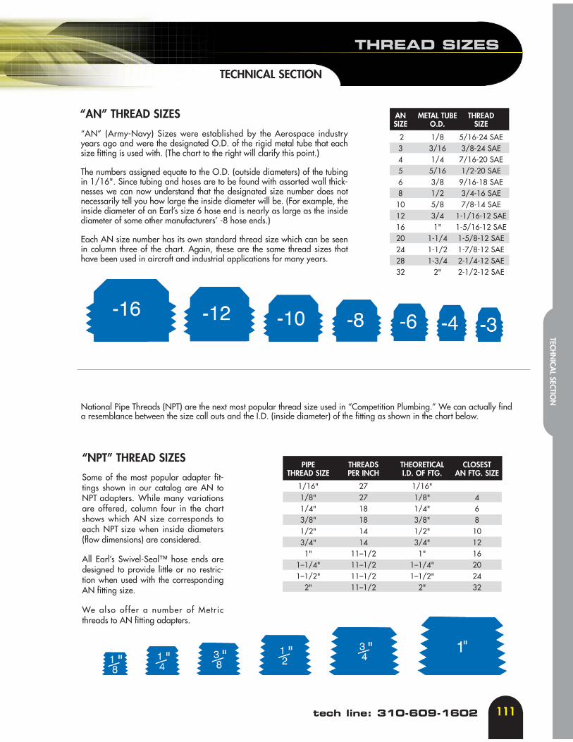
“AN” THREAD SIZES
“AN” (Army-Navy) Sizes were established by the Aerospace industryyears ago and were the designated O.D. of the rigid metal tube that eachsize fitting is used with. (The chart to the right will clarify this point.)
The numbers assigned equate to the O.D. (outside diameters) of the tubingin 1/16". Since tubing and hoses are to be found with assorted wall thick-nesses we can now understand that the designated size number does notnecessarily tell you how large the inside diameter will be. (For example, theinside diameter of an Earl’s size 6 hose end is nearly as large as the insidediameter of some other manufacturers’ -8 hose ends.)
Each AN size number has its own standard thread size which can be seenin column three of the chart. Again, these are the same thread sizes thathave been used in aircraft and industrial applications for many years.
AN METAL TUBE THREADSIZE O.D. SIZE
2 1/8 5/16-24 SAE3 3/16 3/8-24 SAE4 1/4 7/16-20 SAE5 5/16 1/2-20 SAE6 3/8 9/16-18 SAE8 1/2 3/4-16 SAE10 5/8 7/8-14 SAE12 3/4 1-1/16-12 SAE16 1" 1-5/16-12 SAE20 1-1/4 1-5/8-12 SAE24 1-1/2 1-7/8-12 SAE28 1-3/4 2-1/4-12 SAE32 2" 2-1/2-12 SAE
“NPT” THREAD SIZES
Some of the most popular adapter fit-tings shown in our catalog are AN toNPT adapters. While many variationsare offered, column four in the chartshows which AN size corresponds toeach NPT size when inside diameters(flow dimensions) are considered.
All Earl’s Swivel-Seal™ hose ends aredesigned to provide little or no restric-tion when used with the correspondingAN fitting size.
We also offer a number of Metricthreads to AN fitting adapters.
National Pipe Threads (NPT) are the next most popular thread size used in “Competition Plumbing.” We can actually finda resemblance between the size call outs and the I.D. (inside diameter) of the fitting as shown in the chart below.
PIPE THREADS THEORETICAL CLOSESTTHREAD SIZE PER INCH I.D. OF FTG. AN FTG. SIZE
1/16" 27 1/16"1/8" 27 1/8" 41/4" 18 1/4" 63/8" 18 3/8" 81/2" 14 1/2" 103/4" 14 3/4" 121" 11–1/2 1" 16
1–1/4" 11–1/2 1–1/4" 201–1/2" 11–1/2 1–1/2" 24
2" 11–1/2 2" 32

The following chart are the actual size of B nuts used on hoseends and adapters.
Pressure Test All HoseAssemblies BeforeInstallation!
B-NUT CHART
HOSE TO HOSE END COMPATIBILITY CHART
Pro-Lite 350™
Perform-O-Flex™
Auto-Flex™
Ultra-Flex 650™
Super Stock™
Power Steering™
Speed-Flex™
Swive
l-Sea
l™Au
to-F
it™Au
to-C
rimp
™
Ultra
-Flex
™Su
per S
tock
™Po
wer S
teerin
gSp
eed-
Seal
™
Hos
es
HoseEnds Au
to M
ate™
112
B-NUT SIZES &HOSE-TO-HOSE END CHART
TECHNICAL SECTION
www.earlsplumbing.com
TECH
NIC
AL
SECT
ION
TORQUE VALUES & ULTRA-FLEX 650™ CRIMP DIMENSIONS
113
TECHNICAL SECTION
tech line: 310-609-1602
TECHN
ICAL SECTIO
N
ALUMINUM STAINLESS STEELDASH SIZE INCH/LVS NEWTON/m INCH/LBS NEWTON/m
MIN-MAX MIN-MAX MIN-MAX MIN-MAX
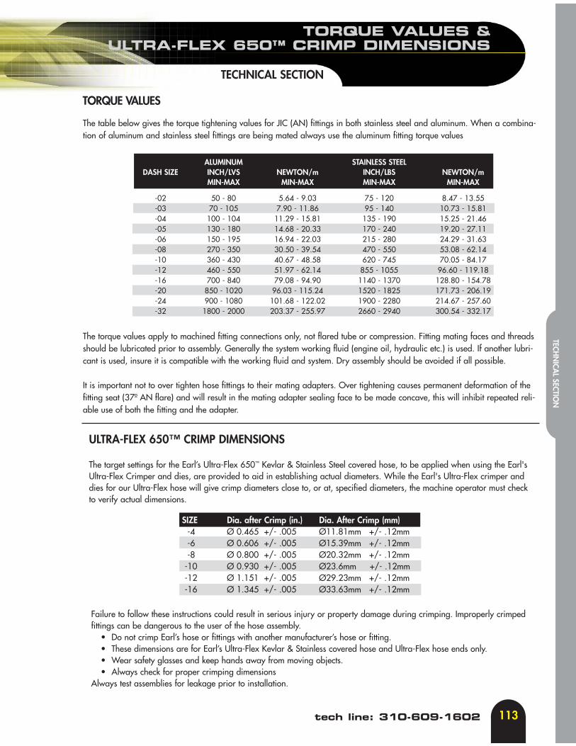
-02 50 - 80 5.64 - 9.03 75 - 120 8.47 - 13.55-03 70 - 105 7.90 - 11.86 95 - 140 10.73 - 15.81-04 100 - 104 11.29 - 15.81 135 - 190 15.25 - 21.46-05 130 - 180 14.68 - 20.33 170 - 240 19.20 - 27.11-06 150 - 195 16.94 - 22.03 215 - 280 24.29 - 31.63-08 270 - 350 30.50 - 39.54 470 - 550 53.08 - 62.14-10 360 - 430 40.67 - 48.58 620 - 745 70.05 - 84.17-12 460 - 550 51.97 - 62.14 855 - 1055 96.60 - 119.18-16 700 - 840 79.08 - 94.90 1140 - 1370 128.80 - 154.78-20 850 - 1020 96.03 - 115.24 1520 - 1825 171.73 - 206.19-24 900 - 1080 101.68 - 122.02 1900 - 2280 214.67 - 257.60-32 1800 - 2000 203.37 - 255.97 2660 - 2940 300.54 - 332.17
The table below gives the torque tightening values for JIC (AN) fittings in both stainless steel and aluminum. When a combina-tion of aluminum and stainless steel fittings are being mated always use the aluminum fitting torque values
The torque values apply to machined fitting connections only, not flared tube or compression. Fitting mating faces and threadsshould be lubricated prior to assembly. Generally the system working fluid (engine oil, hydraulic etc.) is used. If another lubri-cant is used, insure it is compatible with the working fluid and system. Dry assembly should be avoided if all possible.
It is important not to over tighten hose fittings to their mating adapters. Over tightening causes permanent deformation of thefitting seat (37º AN flare) and will result in the mating adapter sealing face to be made concave, this will inhibit repeated reli-able use of both the fitting and the adapter.
TORQUE VALUES
ULTRA-FLEX 650™ CRIMP DIMENSIONS
The target settings for the Earl’s Ultra-Flex 650™ Kevlar & Stainless Steel covered hose, to be applied when using the Earl'sUltra-Flex Crimper and dies, are provided to aid in establishing actual diameters. While the Earl's Ultra-Flex crimper anddies for our Ultra-Flex hose will give crimp diameters close to, or at, specified diameters, the machine operator must checkto verify actual dimensions.
SIZE Dia. after Crimp (in.) Dia. After Crimp (mm)-4 Ø 0.465 +/- .005 Ø11.81mm +/- .12mm -6 Ø 0.606 +/- .005 Ø15.39mm +/- .12mm-8 Ø 0.800 +/- .005 Ø20.32mm +/- .12mm
-10 Ø 0.930 +/- .005 Ø23.6mm +/- .12mm-12 Ø 1.151 +/- .005 Ø29.23mm +/- .12mm-16 Ø 1.345 +/- .005 Ø33.63mm +/- .12mm
Failure to follow these instructions could result in serious injury or property damage during crimping. Improperly crimped fittings can be dangerous to the user of the hose assembly.
• Do not crimp Earl’s hose or fittings with another manufacturer’s hose or fitting.• These dimensions are for Earl’s Ultra-Flex Kevlar & Stainless covered hose and Ultra-Flex hose ends only. • Wear safety glasses and keep hands away from moving objects.• Always check for proper crimping dimensions
Always test assemblies for leakage prior to installation.
114
ASSEMBLY INSTRUCTIONS
TECHNICAL SECTION
www.earlsplumbing.com
TECH
NIC
AL
SECT
ION
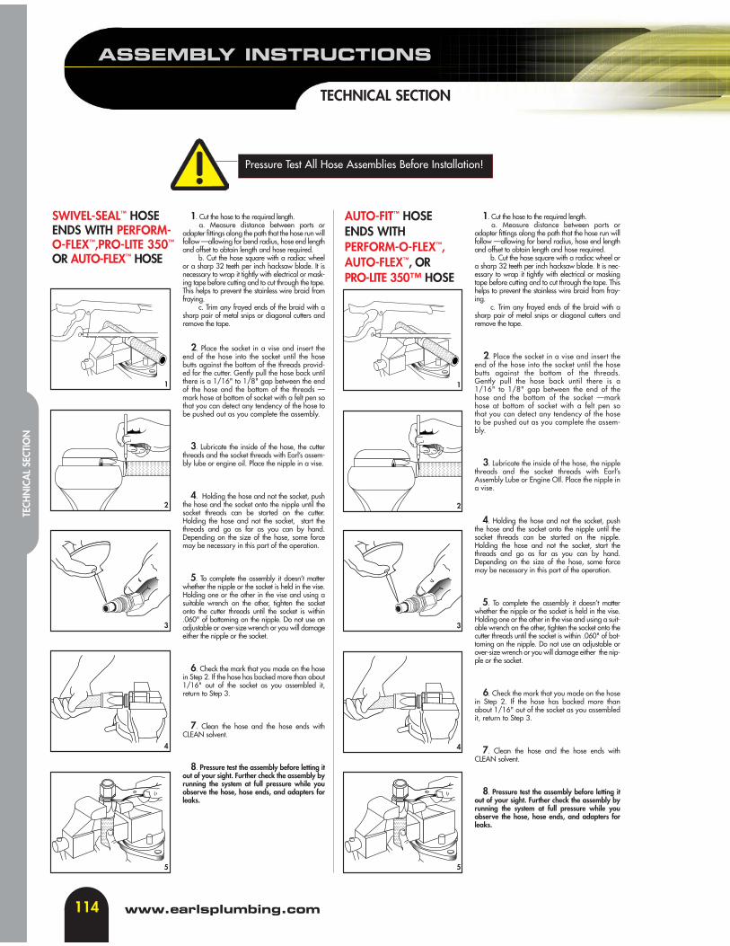
SWIVEL-SEAL™ HOSEENDS WITH PERFORM-O-FLEX™,PRO-LITE 350™
OR AUTO-FLEX™ HOSE
1. Cut the hose to the required length.a. Measure distance between ports or
adapter fittings along the path that the hose run willfollow —allowing for bend radius, hose end lengthand offset to obtain length and hose required.
b. Cut the hose square with a radiac wheelor a sharp 32 teeth per inch hacksaw blade. It isnecessary to wrap it tightly with electrical or mask-ing tape before cutting and to cut through the tape.This helps to prevent the stainless wire braid fromfraying.
c. Trim any frayed ends of the braid with asharp pair of metal snips or diagonal cutters andremove the tape.
2. Place the socket in a vise and insert theend of the hose into the socket until the hosebutts against the bottom of the threads provid-ed for the cutter. Gently pull the hose back untilthere is a 1/16" to 1/8" gap between the endof the hose and the bottom of the threads —mark hose at bottom of socket with a felt pen sothat you can detect any tendency of the hose tobe pushed out as you complete the assembly.
3. Lubricate the inside of the hose, the cutterthreads and the socket threads with Earl’s assem-bly lube or engine oil. Place the nipple in a vise.
4. Holding the hose and not the socket, pushthe hose and the socket onto the nipple until thesocket threads can be started on the cutter.Holding the hose and not the socket, start thethreads and go as far as you can by hand.Depending on the size of the hose, some forcemay be necessary in this part of the operation.
5. To complete the assembly it doesn’t matterwhether the nipple or the socket is held in the vise.Holding one or the other in the vise and using asuitable wrench on the other, tighten the socketonto the cutter threads until the socket is within.060" of bottoming on the nipple. Do not use anadjustable or over-size wrench or you will damageeither the nipple or the socket.
6. Check the mark that you made on the hosein Step 2. If the hose has backed more than about1/16" out of the socket as you assembled it,return to Step 3.
7. Clean the hose and the hose ends withCLEAN solvent.
8. Pressure test the assembly before letting itout of your sight. Further check the assembly byrunning the system at full pressure while youobserve the hose, hose ends, and adapters forleaks.
1. Cut the hose to the required length.a. Measure distance between ports or
adapter fittings along the path that the hose run willfollow —allowing for bend radius, hose end lengthand offset to obtain length and hose required.
b. Cut the hose square with a radiac wheel ora sharp 32 teeth per inch hacksaw blade. It is nec-essary to wrap it tightly with electrical or maskingtape before cutting and to cut through the tape. Thishelps to prevent the stainless wire braid from fray-ing.
c. Trim any frayed ends of the braid with asharp pair of metal snips or diagonal cutters andremove the tape.
2. Place the socket in a vise and insert theend of the hose into the socket until the hosebutts against the bottom of the threads.Gently pull the hose back until there is a1/16" to 1/8" gap between the end of thehose and the bottom of the socket —markhose at bottom of socket with a felt pen sothat you can detect any tendency of the hoseto be pushed out as you complete the assem-bly.
3. Lubricate the inside of the hose, the nipplethreads and the socket threads with Earl’sAssembly Lube or Engine OIl. Place the nipple ina vise.
4. Holding the hose and not the socket, pushthe hose and the socket onto the nipple until thesocket threads can be started on the nipple.Holding the hose and not the socket, start thethreads and go as far as you can by hand.Depending on the size of the hose, some forcemay be necessary in this part of the operation.
5. To complete the assembly it doesn’t matterwhether the nipple or the socket is held in the vise.Holding one or the other in the vise and using a suit-able wrench on the other, tighten the socket onto thecutter threads until the socket is within .060" of bot-toming on the nipple. Do not use an adjustable orover-size wrench or you will damage either the nip-ple or the socket.
6. Check the mark that you made on the hosein Step 2. If the hose has backed more thanabout 1/16" out of the socket as you assembledit, return to Step 3.
7. Clean the hose and the hose ends withCLEAN solvent.
8. Pressure test the assembly before letting itout of your sight. Further check the assembly byrunning the system at full pressure while youobserve the hose, hose ends, and adapters forleaks.
AUTO-FIT™ HOSEENDS WITHPERFORM-O-FLEX™,AUTO-FLEX™, ORPRO-LITE 350™ HOSE
1
2
3
4
5
1
2
3
4
5
Pressure Test All Hose Assemblies Before Installation!
ASSEMBLY INSTRUCTIONS
115
TECHNICAL SECTION
tech line: 310-609-1602
TECHN
ICAL SECTIO
N
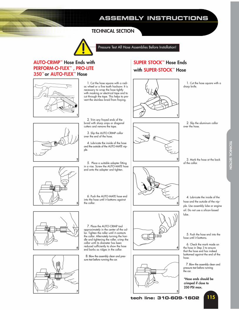
SUPER STOCK™ Hose Ends
with SUPER-STOCK™ Hose
1. Cut the hose square with a radi-ac wheel or a fine tooth hacksaw. It isnecessary to wrap the hose tightlywith masking or electrical tape and tocut through the tape. This helps to pre-vent the stainless braid from fraying.
2. Trim any frayed ends of thebraid with sharp snips or diagonalcutters and remove the tape.
3. Slip the AUTO-CRIMP collarover the end of the hose.
4. Lubricate the inside of the hoseand the outside of the AUTO-MATE nip-ple.
5. Place a suitable adapter fittingin a vise. Screw the AUTO-MATE hoseend onto the adapter and tighten.
6. Push the AUTO-MATE hose endinto the hose until it bottoms againstthe collar.
7. Place the AUTO-CRIMP toolapproximately in the center of the col-lar. Tighten the roller until it contactsthe collar. Alternately turning the han-dle and tightening the roller, crimp thecollar until its diameter has beenreduced sufficiently to show the hoseend barbs as ridges in the collar.
8. Blow the assembly clean and pres-sure test before running the car.
1
2
5
6
7
1
2
3
4
5
1. Cut the hose square with asharp knife.
2. Slip the aluminum collarover the hose.
3. Mark the hose at the back of the collar.
4. Lubricate the inside of the hose and the outside of the nip-ple. Use assembly lube or engineoil. Do not use a silicon-basedlube.
5. Push the hose end into thehose until it bottoms.
6. Check the mark made onthe hose in Step 3 to ensure that the hose end has indeedbottomed against the end of thehose.
7. Blow the assembly clean and pressure test before running the car.
AUTO-CRIMP™ Hose Ends withPERFORM-O-FLEX™ , PRO-LITE350™ or AUTO-FLEX™ Hose
Pressure Test All Hose Assemblies Before Installation!
*Hose ends should becrimped if close to 250 PSI max.
116
ASSEMBLY INSTRUCTIONS
TECHNICAL SECTION
www.earlsplumbing.com
TECH
NIC
AL
SECT
ION
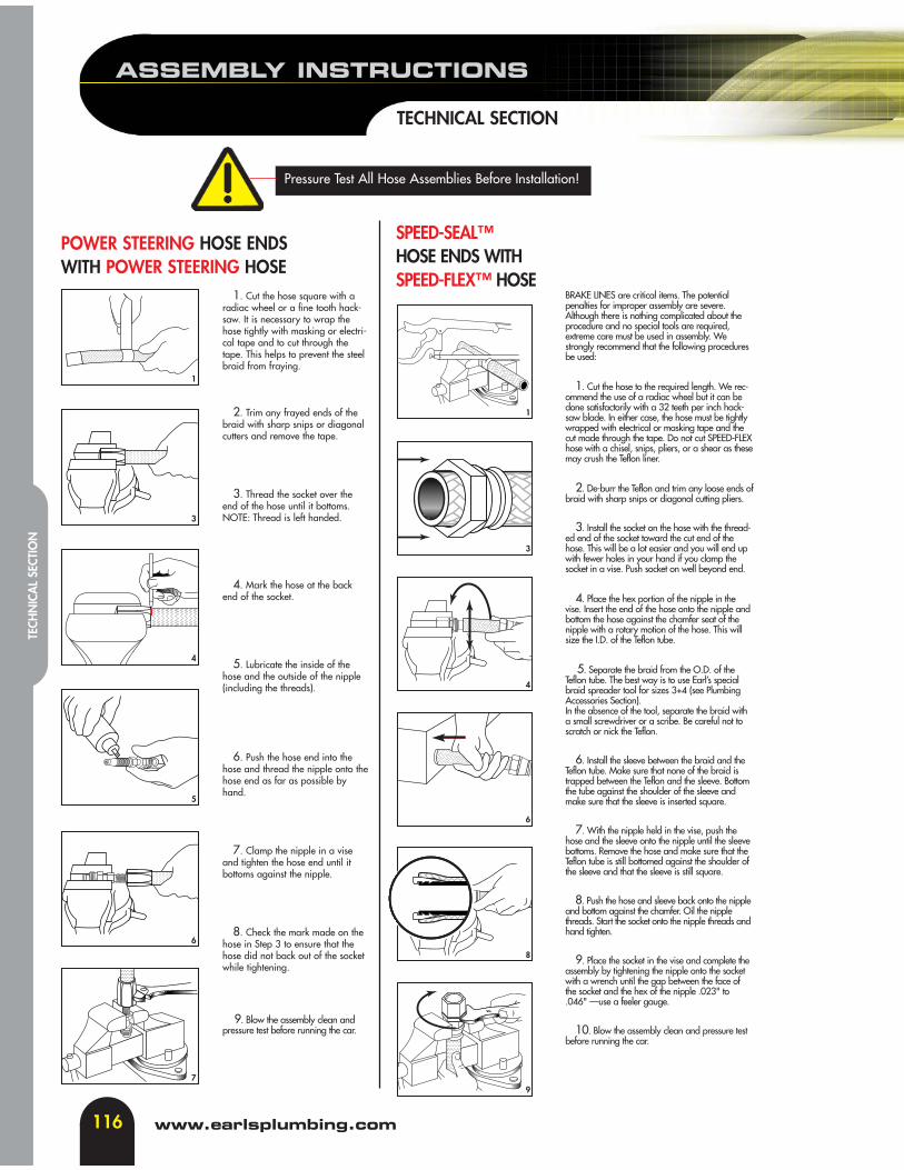
POWER STEERING HOSE ENDSWITH POWER STEERING HOSE
1. Cut the hose square with aradiac wheel or a fine tooth hack-saw. It is necessary to wrap thehose tightly with masking or electri-cal tape and to cut through thetape. This helps to prevent the steelbraid from fraying.
2. Trim any frayed ends of thebraid with sharp snips or diagonalcutters and remove the tape.
3. Thread the socket over theend of the hose until it bottoms.NOTE: Thread is left handed.
4. Mark the hose at the backend of the socket.
5. Lubricate the inside of thehose and the outside of the nipple(including the threads).
6. Push the hose end into thehose and thread the nipple onto thehose end as far as possible byhand.
7. Clamp the nipple in a viseand tighten the hose end until itbottoms against the nipple.
8. Check the mark made on thehose in Step 3 to ensure that thehose did not back out of the socketwhile tightening.
9. Blow the assembly clean andpressure test before running the car.
BRAKE LINES are critical items. The potentialpenalties for improper assembly are severe.Although there is nothing complicated about theprocedure and no special tools are required,extreme care must be used in assembly. Westrongly recommend that the following proceduresbe used:
1. Cut the hose to the required length. We rec-ommend the use of a radiac wheel but it can bedone satisfactorily with a 32 teeth per inch hack-saw blade. In either case, the hose must be tightlywrapped with electrical or masking tape and thecut made through the tape. Do not cut SPEED-FLEXhose with a chisel, snips, pliers, or a shear as thesemay crush the Teflon liner.
2. De-burr the Teflon and trim any loose ends ofbraid with sharp snips or diagonal cutting pliers.
3. Install the socket on the hose with the thread-ed end of the socket toward the cut end of thehose. This will be a lot easier and you will end upwith fewer holes in your hand if you clamp thesocket in a vise. Push socket on well beyond end.
4. Place the hex portion of the nipple in thevise. Insert the end of the hose onto the nipple andbottom the hose against the chamfer seat of thenipple with a rotary motion of the hose. This willsize the I.D. of the Teflon tube.
5. Separate the braid from the O.D. of theTeflon tube. The best way is to use Earl’s specialbraid spreader tool for sizes 3+4 (see PlumbingAccessories Section). In the absence of the tool, separate the braid witha small screwdriver or a scribe. Be careful not toscratch or nick the Teflon.
6. Install the sleeve between the braid and theTeflon tube. Make sure that none of the braid istrapped between the Teflon and the sleeve. Bottomthe tube against the shoulder of the sleeve andmake sure that the sleeve is inserted square.
7. With the nipple held in the vise, push thehose and the sleeve onto the nipple until the sleevebottoms. Remove the hose and make sure that theTeflon tube is still bottomed against the shoulder ofthe sleeve and that the sleeve is still square.
8. Push the hose and sleeve back onto the nippleand bottom against the chamfer. Oil the nipplethreads. Start the socket onto the nipple threads andhand tighten.
9. Place the socket in the vise and complete theassembly by tightening the nipple onto the socketwith a wrench until the gap between the face ofthe socket and the hex of the nipple .023" to.046" —use a feeler gauge.
10. Blow the assembly clean and pressure testbefore running the car.
SPEED-SEAL™HOSE ENDS WITH SPEED-FLEX™ HOSE
1
3
4
5
6
7
1
3
4
6
8
9
Pressure Test All Hose Assemblies Before Installation!
ASSEMBLY INSTRUCTIONS
117
TECHNICAL SECTION
tech line: 310-609-1602
TECHN
ICAL SECTIO
N
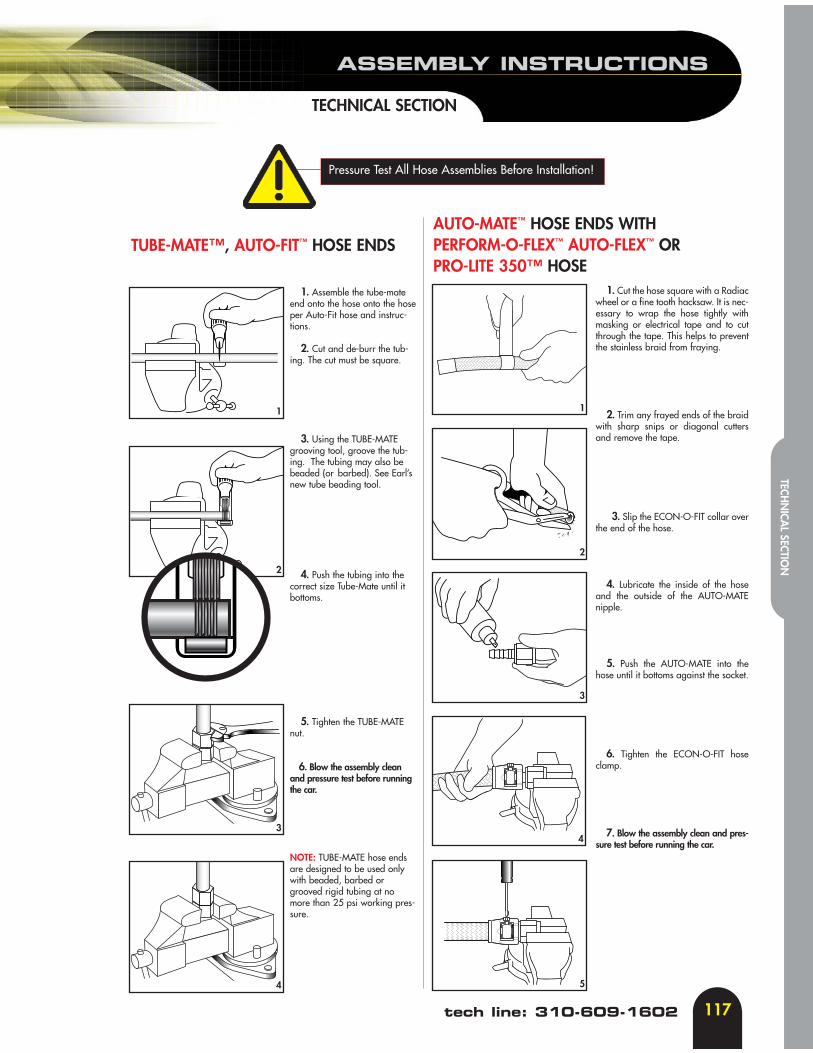
1. Assemble the tube-mateend onto the hose onto the hoseper Auto-Fit hose and instruc-tions.
2. Cut and de-burr the tub-ing. The cut must be square.
3. Using the TUBE-MATEgrooving tool, groove the tub-ing. The tubing may also bebeaded (or barbed). See Earl’snew tube beading tool.
4. Push the tubing into the correct size Tube-Mate until itbottoms.
5. Tighten the TUBE-MATEnut.
6. Blow the assembly cleanand pressure test before runningthe car.
NOTE: TUBE-MATE hose endsare designed to be used onlywith beaded, barbed orgrooved rigid tubing at nomore than 25 psi working pres-sure.
TUBE-MATE™, AUTO-FIT™ HOSE ENDS
1. Cut the hose square with a Radiacwheel or a fine tooth hacksaw. It is nec-essary to wrap the hose tightly withmasking or electrical tape and to cutthrough the tape. This helps to preventthe stainless braid from fraying.
2. Trim any frayed ends of the braidwith sharp snips or diagonal cuttersand remove the tape.
3. Slip the ECON-O-FIT collar overthe end of the hose.
4. Lubricate the inside of the hoseand the outside of the AUTO-MATEnipple.
5. Push the AUTO-MATE into thehose until it bottoms against the socket.
6. Tighten the ECON-O-FIT hoseclamp.
7. Blow the assembly clean and pres-sure test before running the car.
1
2
3
4 5
4
3
2
1
AUTO-MATE™ HOSE ENDS WITH PERFORM-O-FLEX™ AUTO-FLEX™ ORPRO-LITE 350™ HOSE
Pressure Test All Hose Assemblies Before Installation!
118
ASSEMBLY INSTRUCTIONS
TECHNICAL SECTION
www.earlsplumbing.com
TECH
NIC
AL
SECT
ION
1.Prepare to cut UltraFlex 650 hose. Wrap hose tightly with thin packing tape to prevent Kevlar braid from fraying during cutting.
2.Use the Earl’s UltraFlex Hand HoseCutter to cut hose. Use a sharp blade as to not crush the Teflon®
hose during the cutting process.
3.Cut hose square or perpendicular to centerline of hose. No loose or fraying Kevlar braids are to be present.
4.Insert crimp collar onto UltraFlex hose. Do not remove thin tape as adhesive from tape might unravel Kevlar braid.
5.Push UltraFlex hose into crimp collar and verify that hose end bottoms inside of collar.
6.Insert UltraFlex fitting nipple into collar and hose assembly as shown.
7.Prepare the UltraFlex Crimper for operation.
8.Verify correct size crimp die. When inserting die into crimper insure that the bottom of die (shown) mates correctly with die bowl and diamond shaped features in die bowl.
9.Top of crimp die shown in die bowl. Verify die sets correctly in die bowl!
ULTRA-FLEX™ HOSE ENDSWITH ULTRA-FLEX 650™ HOSE

ASSEMBLY INSTRUCTIONS
119
TECHNICAL SECTION
tech line: 310-609-1602
TECHN
ICAL SECTIO
N
10. Gently push down onto crimp die to insert and center die ring on top of crimp die below pusher. Verify that bottom of crimp die is seated correctly in die bowl. Prepare to install pusher onto crimper.
11.Insert and position the hose and fitting assembly into crimp from below. Verify that crimp collar seats correctly in crimp die.
12.While holding hose and fitting into position, begin pumping hand pump until die ring contacts crimper base plate. Release pressure by turning triangular knob on valve.
13. Remove hose and fitting assembly through bottom of die ring and inspect crimp on hose assembly.
14.Measure crimp diameter to ensure proper crimp diameter has been achieved. Refer to crimp chart dimension chart.
ULTRA-FLEX 650™ CRIMP DIMENSIONSThe target settings for the Earl’s Ultra-Flex 650™ Kevlar & Stainless Steel covered hose, to be applied when using the Earl'sUltra-Flex Crimper and dies, are provided to aid in establishing actual diameters. While the Earl's Ultra-Flex crimper anddies for our Ultra-Flex hose will give crimp diameters close to, or at, specified diameters, the machine operator must checkto verify actual dimensions.
SIZE Dia. after Crimp (in.) Dia. After Crimp (mm)-4 Ø 0.465 +/- .005 Ø11.81mm +/- .12mm -6 Ø 0.606 +/- .005 Ø15.39mm +/- .12mm-8 Ø 0.800 +/- .005 Ø20.32mm +/- .12mm
-10 Ø 0.930 +/- .005 Ø23.6mm +/- .12mm-12 Ø 1.151 +/- .005 Ø29.23mm +/- .12mm-16 Ø 1.345 +/- .005 Ø33.63mm +/- .12mm
Failure to follow these instructions could result in serious injury or property damage during crimping. Improperly crimped fittings can be dangerous to the user of the hose assembly.
• Do not crimp Earl’s hose or fittings with another manufacturer’s hose or fitting.• These dimensions are for Earl’s Ultra-Flex Kevlar & Stainless covered hose and Ultra-Flex hose ends only. • Wear safety glasses and keep hands away from moving objects.• Always check for proper crimping dimensions
Always test assemblies for leakage prior to installation.
ULTRA-FLEX™ HOSE ENDSWITH ULTRA-FLEX 650™ HOSE - (CONT’D)

120
HOSE ROUTING GUIDE
TECHNICAL SECTION
www.earlsplumbing.com
TECH
NIC
AL
SECT
ION
1. Provide for length change. 2. Avoid twisting and orient properly.
3. Protect from hazardous environment. 4. Avoid mechanical strain.
5. Use proper bend radius. 6. Use proper bend radius (cont’d).
7. Secure for protection. 8. Avoid improper hose movement..
In straight hose installations, allow enough slack in thehose line to provide for changes in length that willoccur when pressure is applied. This change in lengthcan be from +2% to -4%.
Do not twist during installation. This can be determinedby the printed layline on the hose. Pressure applied toa twisted hose can cause hose failure or loosening ofconnections.
Keep hose away from hot parts. High ambient temper-ature will shorten hose life. If you can not route it awayfrom heat source, insulate it.
Use elbows and adapters in the installation to relievestrain on the assembly and to provide easier andneater installation that are accessible for inspectionand maintenance.
Keep the bend radius of the hose as large as possibleto avoid collapsing of the hose and restriction of flow.Follow catalog specs on minimum bend radii.
Minimum bend radius is measured on the inside bend ofthe hose. To determine minimum bend, divide the totaldistance between ends (B length) by 2. For example, B=6,minimum bend radius=3.
Install hose runs to avoid rubbing or abrasion. Use Earl’sHose Clamps to support long runs of hose or to keep awayfrom moving parts. It is important that the clamps not allowthe hose to move. This movement will cause abrasion andtemperature hose failure.
Make sure relative motion of the machine componentsproduces bending rather than twisting of the hose.Hose should be routed so that the flex is in the sameplane as the equipment movement.
WRONG
RIGHT
WRONG RIGHT
WRONG
RIGHT
WRONG RIGHT
WRONG RIGHT
WRONG RIGHTWRONG
RIGHT
3.00”
6.00”
B
CHECK VALVE FEATURES& SPECIFICATIONS
121
TECHNICAL SECTION
tech line: 310-609-1602
TECHN
ICAL SECTIO
N
ZERO LEAKAGE (Less Than 1 D.P.M.)FULL FLOW with Low Opening Pressure
FEATURES
SPECIFICATIONS
Service Application: Water, Fuel, OilTemperature Range: -70 F to 350 FType of Port: Male 37 Flare with SAE thread
MATERIALS
Body and Cap: 6061 T6 Aluminum Alloy - Hard AnodizedInternal Parts: 6061 T6 Aluminum Alloy - Hard Anodized and Stainless SteelSeal: Aluminum Crush WasherSeat: Reinforced Viton®
Pressure Range: -6 to -12, 350 P.S.I.Sizes: -4, -6, -8, -10, -12Internal Leakage: .01 cc/min. MaxMounting: Hinge Facing Up
SAE THREAD TUBE A B CPART NO. SIZE SIZE + 0R -.005 + OR - .005 + OR - .005 HEX
253004ERL 7/16-20 1/4 2.375 1.270 .865 7/8253006ERL 9/16-18 3/8 2.370 1.260 .865 7/8253008ERL 3/4-16 1/2 2.645 1.335 .925 15/16253010ERL 7/8-14 5/8 3.285 1.770 1.230 1-1/4253012ERL 1-1/16-12 3/4 3.535 1.810 1.480 1-1/2
Check Valves pg.37
Viton® is a registered trademark ofDuPont Performance Elastomers
122
HEAT EXCHANGER VALUES &COOLING COMPARISON CHART
TECHNICAL SECTION
www.earlsplumbing.com
TECH
NIC
AL
SECT
ION
Narrow Cooler Wide Cooler Extra-Wide CoolerP/N: 2XXXX P/N: 4XXXX P/N: 8XXXX
16 BTU/Min/Tube 38 BTU/Min/Tube 49 BTU/Min/TubeROWS 960 BTU/HR 2280 BTU/HR 2940 BTU/HR7 6720 15960 2050810 9600 22800 2940013 12480 29640 3822016 15360 36480 4704019 18240 43320 5586025 24000 57000 7350034 32640 74520 9996042 40320 95760 12348050 48000 114000 14700060 57600 136800 176400
EARL’S HEAT EXCHANGER VALUESBTU RATING/HOUR0.55 GPM/TUBE @ 55MPH
We tested our coolers against a leading tube & fin stack plate design on a high performance engine dyno. The test comparedthe pressure drop between the oil inlet and outlet of each cooler and the temperature drop during the test. The heat exchang-ers were plumbed with -10AN Pro-Lite 350™ hose to a Chevrolet 355 cubic inch Holley carbureted engine with headers. Thetest engine was mounted inside an engine dyno test cell. The tests were conducted with engine water temperature stabilized at180º Fahrenheit and engine oil temperature stabilized at 227º Fahrenheit. Test cell ambient temperature was 94º Fahrenheit.All testing was done with engine speed at 2800 RPM. To simulate road speed, a cooling fan was erected to force air throughthe coolers at approximately 60ft/sec (41 mph).
Part # 41310 Tube/FinSurface Area(In2) 34 67.5Engine Water Temp. (Fº) 177 180Oil Temp - In (Fº) 227 221Oil Temp - Out (Fº) 207 203Oil Temp Difference -20 -18Oil Pressure - In (PSI) 58.6 59Oil Pressure - Out (PSI) 57.6 56Oil Pressure Difference -1.0 -3.0Engine Speed (RPM) 2800 2800
Conclusion: Tube style & fin style cooler needed to be twice the size in surface area for the same heat rejection comparedto the Earl’s oil cooler.

TYPICAL PLUMBING OF COOLER
50% Efficient between radiator and motor75% Efficient between air conditioning condenser and radiator
100% Efficient in front of radiator and air conditioning condenser
AirFlow
AirConditioning Condenser
WaterRadiator
EARL’S HEAT EXCHANGEAS AUXILIARY RADIATOR
1. Place the flapper Check Valve (FCV) in the return line FROM the cooler TO the thermostat.
2. The direction of free flow through the FCV MUST be towards the thermostat.
3. See the drawing for the location of the thermostat. The port marked “INLET” on the thermostat is the inlet from the engine. Be sure to plumb the thermostat according to the drawing
The outstanding heat transfer characteristic of our Tep-A-Cure™ Oil Coolers is achieved in part by using very thin aluminumsheets for the oil tubes. Every cooler is tested to 175 psi at our plant. Burst tests indicate pressures of up to 350 psi are tolerat-ed before cooler failure.
Stomping on the accelerator while the engine is still cold with a sticky bypass valve on your engine can combine to create apressure spike far exceeding 350 psi. If you can’t break the “throttle stomping while the engine is still cold” habit, you mustinstall a check valve (FCV) and a thermostat (P/N 501ERL) in your oil system, as shown in the diagram.
TYPICAL PLUMBING OF COOLER
123
TECHNICAL SECTIONS
tech line: 310-609-1602
TECHN
ICAL SECTIO
N
124
HOSE END SPECIFICATIONS
TECHNICAL SECTION
www.earlsplumbing.com
TECH
NIC
AL
SECT
ION

HOSE END SPECIFICATIONS
125
TECHNICAL SECTION
tech line: 310-609-1602
TECHN
ICAL SECTIO
N
126
HOSE END SPECIFICATIONS
TECHNICAL SECTION
www.earlsplumbing.com
TECH
NIC
AL
SECT
ION
HOSE END SPECIFICATIONS
127
TECHNICAL SECTION
tech line: 310-609-1602
TECHN
ICAL SECTIO
N
128
HOSE END SPECIFICATIONS
TECHNICAL SECTION
www.earlsplumbing.com
TECH
NIC
AL
SECT
ION

HOSE END SPECIFICATIONS
129
TECHNICAL SECTION
tech line: 310-609-1602
TECHN
ICAL SECTIO
N
130
HOSE END SPECIFICATIONS
TECHNICAL SECTION
www.earlsplumbing.com
TECH
NIC
AL
SECT
ION
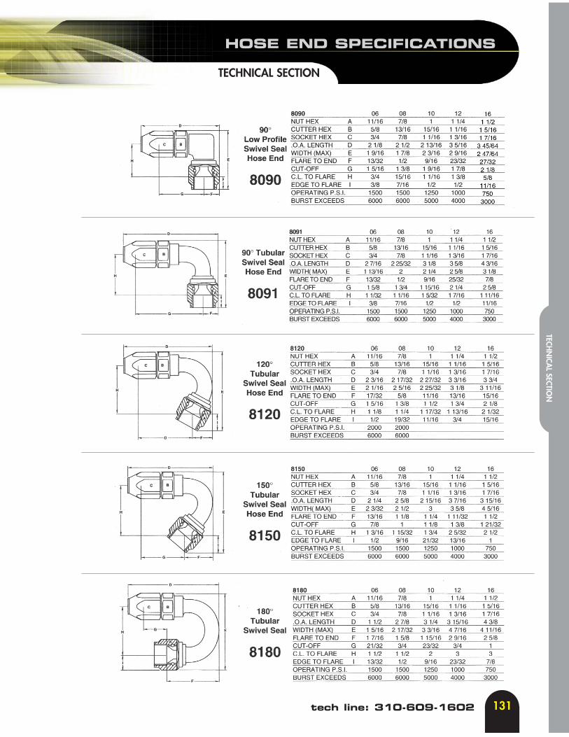
HOSE END SPECIFICATIONS
131
TECHNICAL SECTION
tech line: 310-609-1602
TECHN
ICAL SECTIO
N