solid-state self-healing systems: the diffusion of healing...
TRANSCRIPT

Sains Malaysiana 44(6)(2015): 843–852
Solid-State Self-Healing Systems: The Diffusion of Healing Agent for Healing Recovery
(Sistem Swa-Pemulihan Pepejal: Proses Penyusupan Rawak Agen Pemulihan untuk Perawatan Komposit)
M.S. MD JAMIL*, F.R. JONES, N.N. MUHAMAD & S.M. MAKENAN
ABSTRACT
A clear understanding on the fundamental mechanism in solid state self-healing resin system might significantly improve the optimization of healing performance. The focus of this study was to prove the diffusion (through thermal inter-diffusion) of a linear healing agent within the network matrix resin. The results had demonstrated that 45 to 21 percentage recoveries in fracture toughness (K1C) were observed within the third healing cycles of the healable resin. Based on the optical microscopy, scanning electron microscopy (SEM) and time-of-flight secondary ion mass spectrometry (ToF-SIM) analyst; the diffusion of healing agent was also demonstrated by the change in the morphology and chemical images of the healing agent on the fracture surface specimen, before and after healing process.
Keywords: Chemical image; cooling rate; diffusion; healing efficiency
ABSTRAK
Pemahaman yang jelas berkenaan mekanisme asas dalam sistem swa-pemulihan pepejal boleh meningkatkan keupayaan optimum poses pembaikan polimer. Fokus dalam kajian ini adalah untuk membuktikan proses penyusupan rawak berlaku secara termal oleh agen pemulihan dalam matrik resin. Sebanyak 45 hingga 21 peratus pemulihan direkodkan melalui ujian liat patah dalam 3 kitaran proses pemulihan. Berdasarkan ujian mikroskopik optik, mikroskop elektron imbasan (SEM) dan masa penerbangan spektrokopi jisim atom sekunder (SIMS); proses penyusupan rawak agen pemulihan dapat dibuktikan melalui perubahan morfologi dan pemetaan kimia di permukaan retak sampel pemulihan, sebelum dan selepas pemulihan.
Kata kunci: Kadar penyejukan; pemetaan kimia; penyusupan; proses pemulihan
INTRODUCTION
Composite materials are widely used in industry and exhibit superior properties; e.g. high strength-to-weight and stiffness-to-weight ratios. Despite these advantages, the composite structures are susceptible to macro and/or micro-damage (invisible impact damage) and has the potential to grow in response to fatigue loading ( Mitrovic et al. 2000; Ramesh & Chandra 2012). Therefore, the damage repair at early stage is essential. In response, a new approach of the ‘self-healing system’ has been developed. Self-healing polymers possess the ability to heal in response to damage using resources inherently available to the system. To date, self-healing has been demonstrated by three conceptual approaches: capsule-based healing systems (Lee et al. 2011), vascular healing systems (Norris et al. 2011) and intrinsically healing polymers (Billiet et al. 2013; Guohua et al. 2012; Julia et al. 2013). The intrinsic property of self-healing materials possess a latent self-healing functionality within the matrix that is triggered by an external stimulus, i.e. heat or intense photo illumination, to initiate a healing response (Blaiszik et al. 2010; Diana et al. 2013; Petterson et al. 2012). Fundamentally, the system is based on ionomeric coupling,
thermally reversible reactions, hydrogen bonding, a dispersed meltable thermoplastic phase, or molecular diffusion concept (Bergman & Wudl 2007; Julia et al. 2013; Kalista et al. 2013). Much related work on intrinsic self-healing process has been done based on the concept of molecular diffusion or chain rearrangement for strength recovery at polymer-polymer (crack) interface, also known as ‘solid state self-healing system’ (Diana et al. 2013; Husnugul et al. 2013). This study involve in thermoplastic-thermosetting solid state self-healing system that incorporating a miscible (Blaiszik et al. 2010; Hayes et al. 2007; Jones et al. 2007) thermoplastic additive; poly(bisphenol-A-co-epichlorohydrin) into the thermoset resin. This healing agent was bonded with epoxy matrix through hydrogen bonding and become mobile above the minimum healing temperature for crack closure. The recovery process occurs by the melting and subsequent re-dispersion of the thermoplastic material into the crack plane, filling the crack and interlocking mechanically with the surrounding matrix material (Luo et al. 2009; Russell et al. 2012). The healing efficiency was calculated by measuring the recovery in apparent fracture toughness (K1C) from compact tension tests for the control and healable resins after repeated

844
healing cycles. Hayes et al. (2007) reported the percentage recovery ranging from 43 to 50%, achieved with 7.5% healing agent at temperatures of 130-160°C and multiple cycles of mending were shown to be successful. The aim of this study was to demonstrate the healing effect through a diffusion of the linear healing agent of the healing agent on the surface of micro-fine crack; before and after the healing process.
EXPERIMENTAL DETAILS
MATERIAL AND SAMPLE PREPARATION
The polymer matrix used was a thermosetting resin consisting of diglycidyl ether of bisphenol-A (DGEBA) with of 384.36 g/mol obtained from Delta Resin Ltd, UK. The anhydride curing agent used was nadic methyl anhydride (NMA) while the benzyldimethylamine (BDMA) was used as cationic initiator for the ring opening polymerization, both supplied by Robnor Resin Ltd. Non-reactive Poly(bisphenol-A-co-epichlorohydrin) (or PDGEBA) with of 44000 g/mol; from Sigma Aldrich Ltd., was used as a healing agent based on the calculation of solubility parameters using Hoy Solubility Parameter Software (Jos 2002). The value of solubility parameter of a repeated unit polymeric matrix resin (Figure 1) would be 21.88 which is near to the value of 21.25
for the proposed healing agent. The control (or non-healable) resin was prepared by heating the DGEBA at 90°C for 15 min and mechanically stirred. NMA hardener was added and stirred for 15 min until it was completely dissolved and followed by BDMA for 5 min and further stirring. The ratios by weight of 100.0, 81.2 and 2.0 for the epoxy-hardener-catalyst mixture were used (Zhang 2008){Hayes, 2007b #7}. The
resin mixture was degassed in a vacuum oven at 90°C to eliminate air bubbles before being poured into the silicon mole. The blend was cured in an air convection oven at 90°C for 4 h followed by post curing at 150°C for 2 h before being allowed to cool down to 25°C at 2°C/min. For the self-healing (or healable) resin, the healing agent (7.5 wt. % of PDGEBA) was dissolved into the DGEBA under mechanical stirring at 90°C for approximately 24 h to form a homogeneous solution (Zhang 2008). Afterwards, the method for sample preparation followed the similar procedure of the control resin with the addition of the NMA and BDMA for curing. For healing procedure, the fracture sample were heal at 140°C for 6 h for each healing cycle before it was allowed to cool down to 25°C at 2°C/min. Furthermore, ToF-SIMS analysis was used for characterization of the fracture surfaces of the self-healing resin. However, the healing agent of PDGEBA (with of 44000 g/mol) and DGEBA resin would produce a similar group of secondary ions under the ion beam of the secondary ion mass spectrometer (SIMS) due to their identical chemical structure. To enable chemical images to be prepared using the ToF-SIMS technique, malonate and bromine groups was introduced into the healing agent and the matrix resin, respectively, in order to provide the specific secondary ions for each individual component of this self-healing system. For modified healable resin, DGEBA and Br-DGEBA with the ratio by weight of 80:20 were used as epoxy monomers (Table 1). The mixture was stirred at 90°C for 1 h. For the healing agent, reactive poly(bisphenol A-co-epichlorohydrin) with glycidyl end-group ( of 6100 g/mol) was capped with malonic acid (Oprea et al. 2000). In this synthesis, linear polymer (20 g, 0.003 mol) was introduced to the beaker and melted in an oil
FIGURE 1. The chemical structure of repeat unit resin from the curing of the anhydride (NMA) and the epoxy (DGEBA) under catalyst (tertiary amine)
TABLE 1. Formulation of modified (DGEBA) resin
Ingredient Component Ratio by weightEpoxy monomer
HardenerCatalyst
DGEBA and Br-DGEBA (ratio by weight of 80:20)NMA
BDMA
100.074.12.0

845
bath. The mixture was mechanically stirred at a speed of 40 rpm at 125°C for 30 min. Then, the malonic acid (0.7 g, 0.006 mol) was added slowly into the mixer and stirred at 125°C for 1 h. For ionic neutralization of the acid groups, 0.04 g of magnesium hydroxide, Mg(OH)2 was slowly added to the mixer at 125°C for 15 min, to reduce the possibility of reaction between the carboxylic group of end-capped healing agent and the epoxide group of epoxy resin. This end-capped healing agent was then dissolved in the epoxy monomers (DGEBA and Br-DGEBA) before being cured with NMA and BDMA. Afterwards the method for sample preparation and curing cycle followed the similar procedure with the preparation of control resin.
ASSESSMENT OF HEALING
The healing capability of the resin was calculated based on the Compact Tension test using the specific dimensions corresponding to the British Standard; ISO 13586:2000, as shown in Figure 2. A sharp pre-crack was then created in the samples by gently tapping a fresh razor blade into a machined starter notch. In addition, a 3 mm diameter hole in the plane of the growing crack was introduced to prevent the crack from propagating through the specimen (Figure 2) (Hayes et al. 2007). Thus, the arrested crack was precisely aligned in intimate contact for healing. The fractured specimens of self-healing resin were healed in an air convection oven at 140°C for 6 h in each healing cycle before slowly reducing the temperature to 25°C at a rate of 2 K/min. The sample was loaded to fracture at a test speed of 10 mm/min using tensile testing machine type T5002 from a J.J. Lloyd Instrument. The magnitude of the loads and the corresponding displacements was simultaneously recorded using Easylogger DS1M12 software. The crack’s length was measured visually from both side of each sample using a travelling microscope with the precision of 10 μm. The samples of the healable resin system were tested, alongside reference samples consisting of the control resin sample. The percentage recovery (RK) was calculated from the
average of critical stress intensity factor (K1C) obtained from the Compact Tension test.
RK = (1)
FOURIER-TRANSFORM INFRARED SPECTROMETER (FTIR)
FTIR observation was made with a Perkin-Elmer, S2000 to carry out the spectral analysis. 1-2 mg of the solid sample was mixed with potassium bromide (1:100 mg) and grounded into fine powder before being pressed into thin discs for FTIR measurement. All spectra were recorded at room temperature with the infrared spectra range of 4000-500 cm−1.
OPTICAL MICROSCOPY FOR HEALING ANALYST
Optical images were taken using a Reichert-Jung POLYVAR MET light optical microscope, attached to a CCD Colour Camera model KC-512NTX. Adjustment was made for the compact tension sample dimension (British Standard; ISO 13586:2000), with the specimen width of 3 mm. Due to the sample transparency, the pictures were taken in a transmitted light mode.
TIME-OF-FLIGHT SECONDARY ION MASS SPECTROMETRY (TOF-SIMS)
Time-of-flight secondary ion mass spectrometry (ToF-SIMS) is a surface-sensitive analytical method. It uses a pulsed ion beam to sputter molecular ions from the very outermost surface of the sample with a depth of approximately 1 to 2 nm. This secondary ions or spectrum can give detailed information about the molecular structure and the distribution of various atoms or molecules (chemical imaging) on the material’s surface. TOF-SIMS analysis was carried out on an ION-TOF V (from Münster, Germany) system. A Bismuth liquid metal ion source was employed for mass data acquisition. The baseline pressure of 5 × 10⁻⁷ mbar with an electron flood gun charge neutraliser was used with a primary low ion dose of 5 ×
FIGURE 2. Dimensions of the compact tension test specimens (in mm)

846
1012 ions/cm2. The spectra were collected across an area of 300 × 300 μm area with a cycle time of 100 μs (Vickerman & Briggs 2001). The surface from a complete fracture of a compact tension test specimen showing the studied area is shown in Figure 3. IonSpec and IonImage software (ION-TOF, Münster, Germany) were used for the analysis of the SIMS data.
RESULTS AND DISCUSSION
The ‘diffusional solid state self-healing system’ is based on a thermal diffusion of a healing agent within the network matrix resin. The healing agent should be reversibly bonded through hydrogen bonding and upon heating at minimum healing temperature; it diffuse into the crack plane, filling the crack and mechanically interlocking with the surrounding matrix material (Blaiszik 2010; Diana et al. 2013).
THE HEALING EFFICIENCY OF SELF-HEALING RESIN SYSTEMS
Compact tension testing has been employed for the assessment of the healing performance. The healing efficiency was investigated by measuring the recovery of fracture toughness (K1C) in self-healing resin system (Hayes et al. 2007; Jones et al. 2007). The load-displacement curves for repeated healing of the control and healable resins were obtained as shown in Figure 4(a)-4(b). To compensate for the residual healing effect in the control resin system (Figure 5(a)), the actual ‘healing efficiency’ (HK) was obtained by correcting the healing process in the control system using (2).
FIGURE 3. Photograph of a fully fractured compact tension specimen, showing the area of interest
SCANNING ELECTRON MICROSCOPY (SEM)
Scanning Electron Microscopy (SEM) was performed under conventional secondary electron imaging conditions using a Camscan Mk 2 model SEM, to observe the fracture surface of control and healable resin specimens (Figure 6). This non-metal sample was made conductive by sputter coated with an ultrathin coating of gold.
TABLE 2. The fracture toughness (K1C), percentage recovery (RK) and healing efficiency (HK) of the control and healable resin after the repeatable healing cycles. The samples were healed at 140ºC
for 6 h at 2°C/min in each healing cycle
Resin Healing cycle K1C (kPa m1/2) RK (%) HK (%)Control (DGEBA)
resin 0123
768 ± 2894 ± 3451 ± 735 ± 8
-12.36.74.7
----
(with 7.5 wt. % of healing agent ( of
44000 g/mol))
0123
736 ± 46422 ± 65278 ± 29195 ± 18
-57.238.125.5
-44.931.420.8
FIGURE 4. The load-displacement curves for repeated healing of the (a) control and (b) healable (containing 7.5 wt. % of HA with of 44000 g/mol) resins from the compact tension test. The samples
were healed at 140ºC for 6 h at 2°C/min in each healing cycle
847
Healing efficiency (HK ) = RK − RK0 (2)
where RK0 is the residual healing effect of control resin
(containing no healing agent). Table 2 showed the healing efficiency data from compact tension test of healable resin (with 7.5 wt. % of HA) after the repeatable healing cycles. 44.9, 31.4 and 20.8% of healing efficiency was recorded after the first, second and third healing cycle, respectively. It is considered that the healing agent would diffuse via reptation through the free volume within the thermosetting resin to the surface of micro-fine crack for closure (Wu et al. 2008; Yamaguchi et al. 2007). Wool (2008) had reported the theory of crack healing via molecular inter-diffusion in polymeric material involving the process of surface rearrangement, wetting, diffusion and randomization that takes place across the micro-fine crack. In similar concept, Pavlos et al. (2010) proposed a reptation mode; in which an interface between the fracture surfaces was formed by random walk chains from a tube-like region and diffusion by reptation across a polymer-polymer weld line before the chains form new physical cross-links.
DIFFUSION OF HEALING AGENT
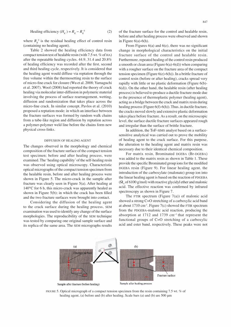
The changes observed in the morphology and chemical composition of the fracture surface of the compact tension test specimen; before and after healing process, were examined. The ‘healing capability’ of the self-healing resin was observed using optical microscopy. Characteristic optical micrographs of the compact tension specimen from the healable resin, before and after healing process were shown in Figure 5. The micro-crack in the sample after fracture was clearly seen in Figure 5(a). After healing at 140°C for 6 h, this micro-crack was apparently healed as shown in Figure 5(b); in which the crack has been filled and the two fracture surfaces were brought into contact. Considering the diffusion of the healing agent to the crack surface during the healing process, SEM examination was used to identify any change of the surface morphologies. The reproducibility of the SEM technique was tested by comparing one original sample surface and its replica of the same area. The SEM micrographs results
of the fracture surface for the control and healable resin, before and after healing process were observed and shown in Figure 6(a)-6(h). From Figures 6(a) and 6(e), there was no significant change in morphological characteristics on the initial fracture surface of the control and healable resin. Furthermore, repeated healing of the control resin produced a smooth or clean area (Figure 6(a)-6(d)) when comparing with a rougher surface on the fracture area of the compact tension specimen (Figure 6(e)-6(h)). In a brittle fracture of control resin (before or after healing), cracks spread very rapidly with little or no plastic deformation (Figure 6(b)-6(d)). On the other hand, the healable resin (after healing process) is believed to produce a ductile fracture mode due to the presence of thermoplastic polymer (healing agent), acting as a bridge between the crack and matrix resin during healing process (Figure 6(f)-6(h)). Thus, in ductile fracture, the cracks moved slowly and extensive plastic deformation takes place before fracture. As a result, on the microscopic level, the surface ductile fracture surfaces appeared rough and irregular than the surface of brittle fracture. In addition, the ToF-SIMS analyst based on a surface-sensitive analytical was carried out to prove the mobility of healing agent to the crack surface. For this purpose, the alteration to the healing agent and matrix resin was necessary due to their identical chemical composition. For matrix resin, Brominated DGEBA (Br-DGEBA) was added to the matrix resin as shown in Table 1. These provide the specific Brominated group ions for the modified DGEBA resin (Figure 9). For linear healing agent, the introduction of the carboxylate (malonate) group ion into the linear healing agent is based on the reaction of PDGEBA ( of 6100 g/mol) with reactive glycidyl ether and malonic acid. The effective reaction was confirmed by infrared spectroscopy as shown in Figure 7. The FTIR spectrum (Figure 7(a)) of malonic acid showed a strong C=O stretching of a carboxylic acid band at about 1710 cm-1. Figure 7(c) showed the FTIR spectrum from the PDGEBA-malonic acid reaction, producing the absorption at 1712 and 1739 cm−1 that represent the functional groups of C=O stretching of a carboxylic acid and ester band, respectively. These peaks were not
FIGURE 5. Optical micrograph of a compact tension specimen from the resin containing 7.5 wt. % of healing agent, (a) before and (b) after healing. Scale bars (a) and (b) are 500 μm

848
detectable in the PDGEBA spectra. Furthermore, due to the opening of the epoxy ring from this reaction, the reduction in the intensity of the epoxy ring band at 910 cm−1 was observed (Figure 7(b)). Based on the control (DGEBA) resin, modified DGEBA resin and end-capped healing agent (Malonic-PDGEBA), the ToF-SIMS negative ion mass spectra of these components are shown in Figures 8-10. To generate useful information on the nature of surface of self-healing resin systems (Figure 3), it was necessary to
map group of ions indicating the presence of the individual components of the composite (Table 3). To ensure that images could be compared, the pixel intensities were normalized by specifying the maximum number of counts per pixel (Vickerman & Briggs 2001). Furthermore, the overlay images were also generated by overlaying 2 images, assigning the pixel’s brightness of different group ions to the red, green or blue channels of the image (Table 3). It is important to make sure that the addition of Br-DGEBA with DGEBA resin provides the minimal change to
FIGURE 6. SEM micrograph of the crack surface (as shown in Figure 4) from the compact tension specimen of the control ((a)-(d)) and healable (with 7.5 wt. % of HA - of 44000 g/mol) ((e)-(h)) resins, before and after repeatable healing
cycles. In each cycle, the samples were healed at 140ºC for 6 h. Scale bars are 10 μm
FIGURE 7. FTIR spectra in the region 4000-500 cm-1 recorded at room temperature of a) Malonic acid b) PDGEBA (with of 6100 g/mol) c) PDGEBA/Malonic acid reaction

849
FIGURE 8. Low and high resolution ToF-SIMS negative ion mass spectra of the NMA cured DGEBA resin at m/z 93, 133 and 211
FIGURE 9. Low and high resolution ToF-SIMS negative ion mass spectra of the NMA cured Br-DGEBA at m/z 81, 172 and 212
FIGURE 10. Low and high resolution ToF-SIMS negative ion mass spectra of the malonate end-capped PDGEBA ( of 6100 g/mol) in healable resin at m/z 59, 103 and 117
the miscibility of the solution (Table 1). Figure 11 shows the ToF-SIMS compound image on the fracture surface of cured resin; in which DGEBA and Br-DGEBA with the ratio by weight of 80:20 were used as epoxy monomers.
The total negative ions image which represent the morphology of the fracture surface specimen (in 3D) was shown in Figure 11(a). From the total negative ion spectra, the selected secondary ion mass spectra for the NMA cured

850
DGEBA or Br-DGEBA epoxy resin was chosen to represent the compound image of red and green colour as shown in Figures 11(b) and 11(c), respectively. In addition, the overlay image was generated by overlaying these two groups of secondary ion spectra (Figure 11(d)). This overlay image showed the homogeneous distribution of green and red colour. It was concluded that there is no phase separation from the addition of Br-DGEBA in the matrix resin. From the modification of healing agent and matrix resin, the diffusion of linear HA within the matrix resin into fracture surface before and after the healing process were analysed. Figure 12 showed the ToF-SIMS compound image from the selected area of fracture surface in the modified healable resin (with 7.5 wt. % of end-capped HA). The fracture surface topography from the total ion image (in 3D) of the modified healable resin before and after healing were shown in Figures 12(a) and 12(d), respectively. In agreement with the SEM result (Figure
6(f)-6(h)), the healable resin undergoing the healing process produced a ductile or rougher surface on the fracture area (Figure 12(d)). Meanwhile, by comparing with the ion image of Br-DGEBA resin (Figure 12(b)), Figure 12(c) showed a homogeneous distribution of blue colour channel (end-capped healing agent) throughout the dominant green colour (matrix Br-DGEBA resin) background for the initial fracture specimen. However, the blue colour which represents the end-capped healing agent was shown to be further enhanced (or become more prominent) after a simulated healing cycle of the modified healable resin (Figure 12(c)). This emphasised that diffusion of the healing agent within the matrix resin to the crack surface had took place. Based on the results of healing efficiency, optical microscopy, SEM and ToF-SIM analyst; the healing capability of a solid state self-healing system was demonstrated by the diffusion of the linear healing agent within the matrix resin to the surfaces of a crack to provide a mechanism for closure.
TABLE 3. The secondary ions allocated to the different colour channel on studying of characterization of the fracture surfaces of the self-healing resin, before and after healing
Colour channel Representative group Secondary ions mapped Maximum counts per pixelRed
Green
Blue
Resin matrix (DGEBA resin)
Modified Resin matrix (Br-DGEBA resin)
End-capped healing agent
C9H9-, C14H11O2
- and C6H5O-
Br-, C9H8OBr- and C6H4OBr-
C2H3O2-, C4H5O4
- and C3H3O4-
68
92
53
FIGURE 11. The ToF-SIMS negative ion images on the surface of cured modified resin (as describe in Table 1) from the secondary ion spectra of a) total negative ions b) ions group of DGEBA resin (C9H9
-, C14H11O2- and C6H5O
-) c) ions group of Br-DGEBA resin (Br-, C9H8OBr- and C6H4OBr-); and d) overlay of (b) and (c). (Selected area - 300 μm × 300 μm)

851
CONCLUSION
In conclusion, the effects of diffusion of the healing agent and healing efficiency, along with their correlation to the free volume, have been demonstrated. 45-21 percentage of healing efficiency of healable resin from the compact tension test was recorded within the third healing cycle. The linear healing agent diffuse via reptation within the matrix resin; consisting of free volume, to the surface of micro-fine crack for closure. The optical microscopy, SEM micrograph and ToF-SIM analyst were used to demonstrate the diffusion of healing agent based the change in the morphology and chemical images of the distribution of the healing agent on the fracture surface of the compact tension test specimen.
ACKNOWLEDGEMENTS
The authors acknowledge the financial support of this study by Government of Malaysia through grant number of FRGS/1/2012/SE07/UKM/03/1, GGPM-2012-014 and ERGS/1/2012/TK04/UKM/03/3. The authors also wish to thank the University of Sheffield and National University of Malaysia for the continuous support of this project.
REFERENCES
Bergman, S.D. & Wudl, F. 2007. Re-mendable polymers. In Self Healing Materials: An Alternative Approach to 20 Centuries. The Nertherland: Springer. pp 45-62.
Billiet, S., Hillewaere, X.K., Teixeira, R.F. & Du Prez, F.E. 2013. Chemistry of crosslinking processes for self-healing polymers. Macromolecular Rapid Communications 34(4): 290-309.
Blaiszik, B.J., Kramer, S.L.B., Olugebefola, S.C., Moore, J.S., Sottos, N.R. & White, S.R. 2010. Self-healing polymers and composites. Annual Review of Materials Research 40: 179-211.
Diana, D., Philipp, M. & Wolfgang, B. 2013. Principles of self-healing polymers. In Self-Healing Polymers: From Principles to Applications Self-Healing Polymers, edited by Binder, W.H. USA: Wiley-VCH Verlag GmbH & Co. KGaA. pp. 5-60.
Guohua, D., Fuya, L., Hongxia, Y., Fuyong, L., Chenyang, L., Weixiang, S., Huanfeng, J. & Yongming, C. 2012. Dynamic hydrogels with an environmental adaptive self-healing ability and dual responsive sol-gel transitions. ACS Macromolecules Letter 1(2): 275-279.
Hayes, S.A., Zhang, W., Branthwaite, M. & Jones, F.R. 2007. Self-healing of damage in fibre-reinforced polymer-matrix composites. Journal of The Royal Society Interface 4(13): 381-387.
Husnugul, Y.A., Leyla, E.D. & Erdal, C. 2013. Investigations of self-healing property of chitosan-reinforced epoxy dye composite coatings. Journal of Materials 13: 1-7.
Jones, F.R., Zhang, W. & Hayes, S.A. 2007. Thermally induced self healing of thermosetting resins and matrices in smart composites. In Self Healing Materials: An Alternative Approach to 20 Centuries. The Nertherland. Springer. pp. 69-81.
FIGURE 12. The ToF-SIMS negative ion images on the fracture surface of a compact tension specimen for modified healable resin (with 7.5 wt. % of end-capped HA), (a)-(c) before; and (d)-(e) after healing process. Samples were healed at 140ºC for 6 h. ToF-SIMS compound image consist of the secondary ion spectra of (a, d) total negative ions; (b) ions group of Br-DGEBA resin; and
(c, e) overlay of ions group of Br-DGEBA resin and end-capped HA. (Selected area - 300 μm × 300 μm)

852
Jos, A. 2002. Hoy Solubility Parameter Calculation. http://www. compchemcons.com/products/index.html#Hoy.
Julia, K., Steffi, S., Stephanie, H., Juergen, V., Martin, D.H. & Ulrich, S.S. 2013. One-component intrinsic self-healing coatings based on reversible crosslinking by diels–alder cycloadditions. Macromolecular Chemistry and Physics 214(14): 1636-1649.
Kalista, S.J., John, R.P. & Russell, J.V. 2013. Effect of ionic content on ballistic self-healing in EMAA copolymers and ionomers. Polymer Chemistry 4: 4910-4926.
Lee, J., Bhattacharyya, D., Zhang, M.Q. & Yuan, Y.C. 2011. Fracture behaviour of a self-healing microcapsule-loaded epoxy system. Express Polymer Letters 5(3): 246-253.
Luo, X., Ou, R., Eberly, D.E., Singhal, A., Viratyaporn, W. & Mather, P.T. 2009. A thermoplastic/thermoset blend exhibiting thermal mending and reversible adhesion. Applied Materials and Intefaces 1(3): 612-620.
Mitrovic, M., Hahn, H.T., Carman, G.P. & Shyprykevich, P. 2000. Effect of loading parameters on the fatigue behavior of impact damage composite laminates. Composite Science and Technology 59: 2059-2078.
Norris, C.J., Bond, I.P. & Trask, R.S. 2011. The role of embedded bioinspired vasculature on damage formation in self-healing carbon fibre reinforced composites. Composites: Part A 42: 639-648.
Oprea, S., Vlad, S., Stanciu, A. & Macoveanu, M. 2000. Epoxy urethane acrylate. European Polymer Journal 76: 373-378.
Pavlos, G.P., Iliopoulos, A.C., Tsoutsouras, V.G., Karakatsanis, L.P. & Pavlos, E.G. 2010. Spatiotemporal chaos in distributed systems: Theory and practice. In Chaotic Systems: Theory and Applications, edited by Skiadas, C.H. & Dimotikalis, I. Singapore: World Scientific. pp. 268-283.
Peterson, A.M., Harsha Kotthapalli, M., Aflal, M., Rahmathullah & Palmese, G.R. 2012. Investigation of interpenetrating polymer networks for self-healing applications. Composites Science and Technology 72: 330-336.
Ramesh, T. & Chandra, V.S. 2000. Damage and Failure of Composite Materials. The United States: Cambridge University Press.
Russell, J.V., Samuel, M., Dong, Y.W., Sherri, M., Kate, N. & Scott, F. 2012. Confirmation of the healing mechanism in a mendable EMAA-epoxy resin. European Polymer Journal 48(3): 1-26.
Vickerman, J.C. & Briggs, D. 2001. TOF-SIMS: Surface Analysis by Mass Spectroscopy. Chichester: IM Publications.
Wool, R.P. 2008. Self-healing materials: A review. Soft Matterial 4(3): 400-418.
Wu, D.Y., Meure, S. & Solomon, D. 2008. Self-healing polymeric materials: A review of recent developments. Progress in Polymer Science 33(5): 479-522.
Yamaguchi, M., Ono, S. & Terano, M. 2007. Self-repairing property of polymer network with dangling chains. Materials Letters 61(6): 1396-1399.
Zhang, W. 2008. Self healing epoxy resin and composites. Ph.D. thesis, University of sheffield, UK (unpublished).
M.S. Md Jamil*, F.R. Jones, N.N. Muhamad & S.M. MakenanFaculty of Science and Technology Universiti Kebangsaan Malaysia 43600 Bangi, Selangor Darul EhsanMalaysia
M.S. Md Jamil*Department of Materials Science & EngineeringUniversity of Sheffield, S1 3JDUnited Kingdom
*Corresponding author; email: [email protected]
Received: 15 January 2014Accepted: 15 November 2014