solid oxide fuel cell manufacturing overview · solid oxide fuel cell manufacturing overview ......
TRANSCRIPT
Solid Oxide Fuel CellManufacturing Overview
Hydrogen and Fuel Cell TechnologiesManufacturing R&D Workshop
August 11-12, 2011Washington, DC
Mark Richards, Eric Tang, Randy Petri
Copyright © 2011 Versa Power Systems. All Rights Reserved. 2
Contents
Manufacturing development dependencies SOFC elements Cell manufacturing processes
– Materials– Forming– Conditioning
Stack assembly Quality control and testing VPS projected cost reductions in SECA
Copyright © 2011 Versa Power Systems. All Rights Reserved. 3
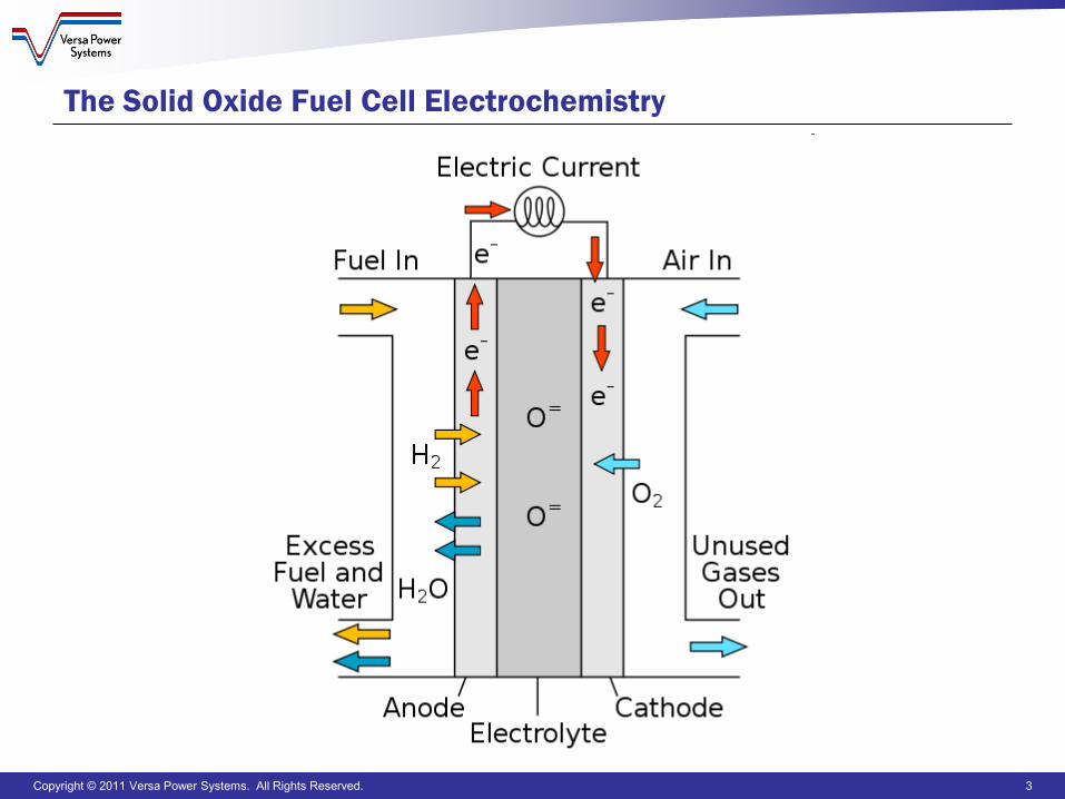
The Solid Oxide Fuel Cell Electrochemistry
Copyright © 2011 Versa Power Systems. All Rights Reserved. 4
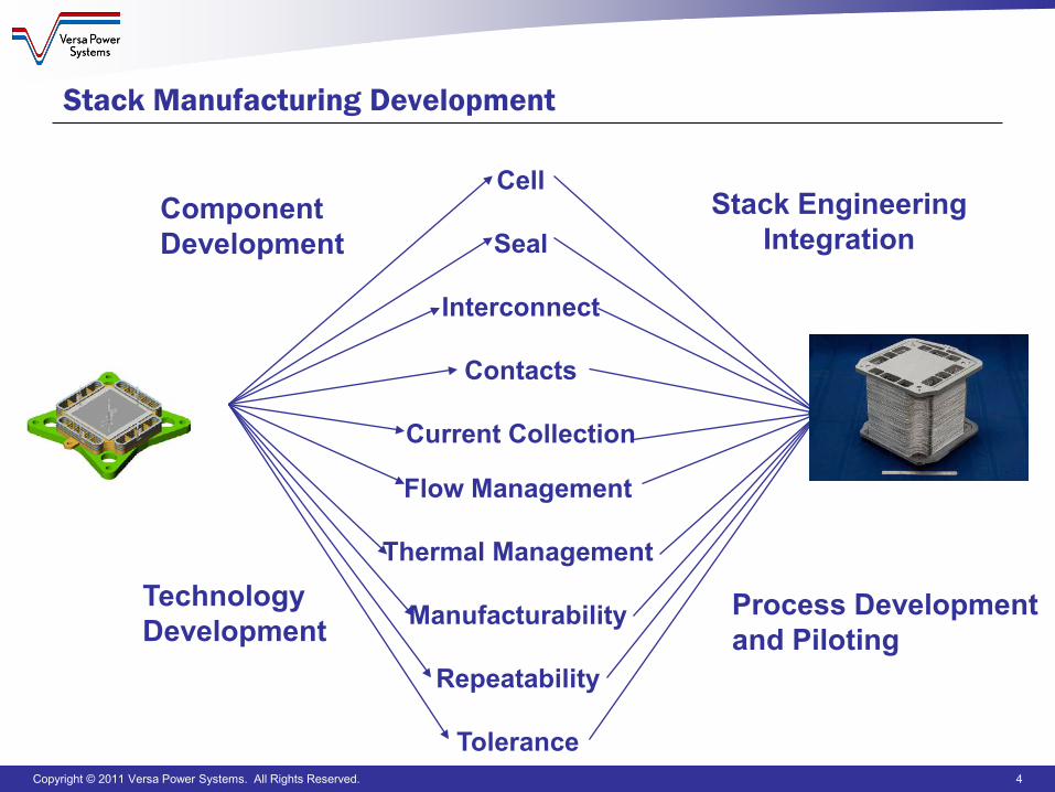
Cell
Seal
Interconnect
Contacts
Current Collection
ComponentDevelopment
TechnologyDevelopment
Flow Management
Thermal Management
Manufacturability
Repeatability
Tolerance
Stack Manufacturing Development
Stack EngineeringIntegration
Process Development and Piloting
Copyright © 2011 Versa Power Systems. All Rights Reserved. 5
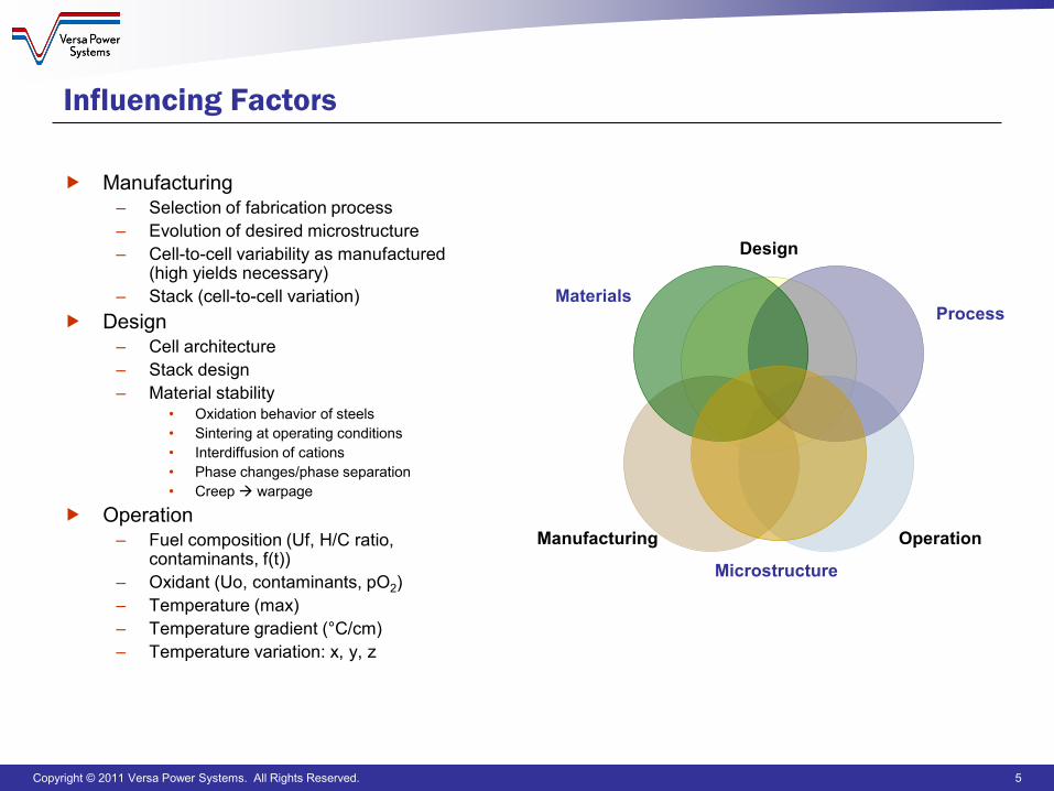
Influencing Factors
Manufacturing– Selection of fabrication process– Evolution of desired microstructure– Cell-to-cell variability as manufactured
(high yields necessary)– Stack (cell-to-cell variation)
Design– Cell architecture– Stack design– Material stability
• Oxidation behavior of steels• Sintering at operating conditions• Interdiffusion of cations• Phase changes/phase separation• Creep warpage
Operation– Fuel composition (Uf, H/C ratio,
contaminants, f(t))– Oxidant (Uo, contaminants, pO2)– Temperature (max)– Temperature gradient (°C/cm)– Temperature variation: x, y, z
Design
OperationManufacturing
MaterialsProcess
Microstructure
Copyright © 2011 Versa Power Systems. All Rights Reserved. 6
SOFC Elements: Independent of Construction
Need to create and join the electrochemical elements (cells)– Anode, cathode, electrolyte– Ceramics
Need to bring reactants to (and from) the cells and keep them where they belong– Flow fields, seals, manifolds– Ceramics or metallics
Need to move electricity from cells– Interconnects, current collection– Ceramics or metallics
Need to move heat from cells and stacks– Active and passive thermal management
Copyright © 2011 Versa Power Systems. All Rights Reserved. 7
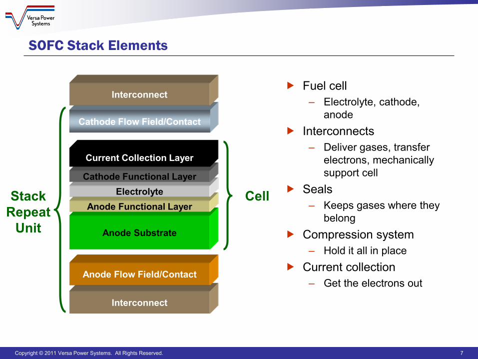
SOFC Stack Elements
Fuel cell– Electrolyte, cathode,
anode Interconnects
– Deliver gases, transfer electrons, mechanically support cell
Seals– Keeps gases where they
belong Compression system
– Hold it all in place Current collection
– Get the electrons out
Anode Substrate
Anode Functional LayerElectrolyte
Cathode Functional Layer
Current Collection Layer
Cell
Cathode Flow Field/Contact
Interconnect
Interconnect
Anode Flow Field/Contact
StackRepeat
Unit
Copyright © 2011 Versa Power Systems. All Rights Reserved. 8
Common Ceramic Manufacturing Steps
Raw material preparation– Powder production– Powder preparation– Sizing
Forming– Tape casting, slip casting, pressing, extrusion, calendaring,
dispensing… – Printing, dip coating, spraying, vapor deposition…
Conditioning – Drying, bisqueing, sintering
Copyright © 2011 Versa Power Systems. All Rights Reserved. 9
Ceramic Raw Material Preparation
Generally, most powders will be procured from suppliers– May require in-house processing such as sizing or purification– Inbound quality control
Further preparation prior to forming or deposition– Additional functional materials may be added as well as binders or
slurry agents– Milling is commonly used to refine and mix materials
Copyright © 2011 Versa Power Systems. All Rights Reserved. 10
Ceramic Forming: Primary Layer
Extrusion– Ceramic with a binder is forced through a mandrel forming the desired
green shape (which can be closed at the leading end) Tape Casting
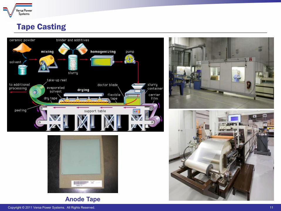
– Ceramic tape is made by uniformly spreading slurry onto a smooth surface
Drying– Both extrusions and tapes need to be dried to allow for handling and
application of other functional elements prior to sintering Cutting
– With extrusions, cutting may result in nearly no loss of material– In a planar cell, tape lost to cutting is a function of cell geometry and
tape size– Recycling of tape lost to cutting is possible
Copyright © 2011 Versa Power Systems. All Rights Reserved. 11
Anode Tape
Tape Casting
Copyright © 2011 Versa Power Systems. All Rights Reserved. 12
Ceramic Forming: Additional Layers
In either a planar or tubular configuration, additional layers are applied to the primary (usually support) layer
Screen printing– Thickness can be limited, reasonable cycle times and cost, planar only
Thermal spraying– Typically uses a flame or plasma, can provide thick coatings, higher depositions
rates than vapor deposition Vapor deposition
– Chemical processes use a fluid precursor which undergoes a chemical change at a solid surface, leaving a solid layer
– Physical processes tend to require a low-pressure vapor environment to function properly
Dip coating– Coating thickness a function of coated surface characteristics, ceramic paint
properties, and number of applications– Equipment is inexpensive but cycle times can be relatively long
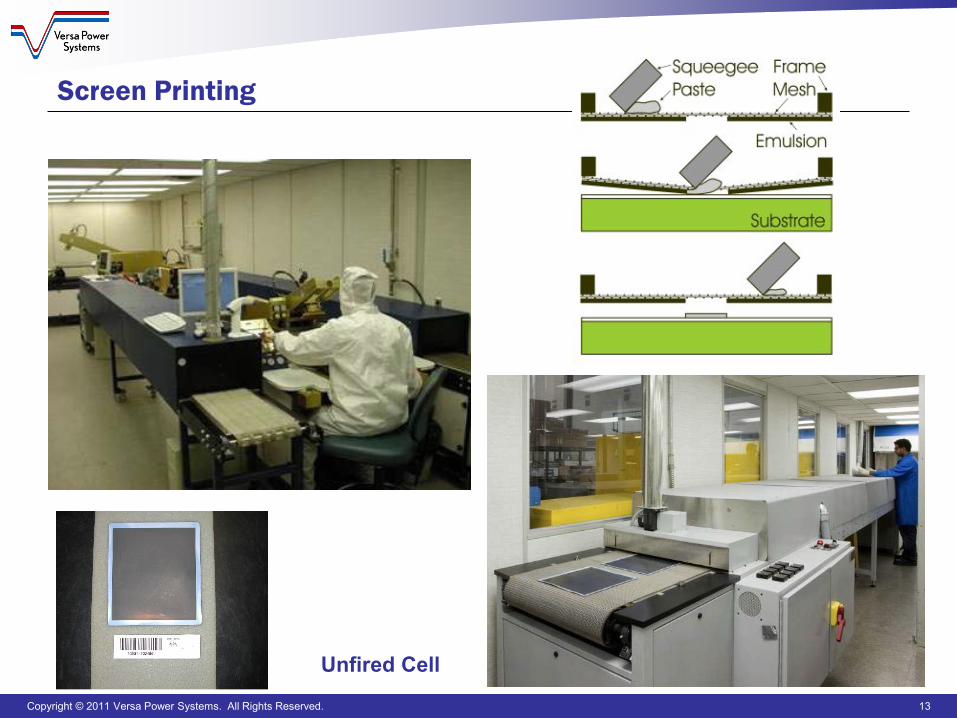
Copyright © 2011 Versa Power Systems. All Rights Reserved. 13
Unfired Cell
Screen Printing
Copyright © 2011 Versa Power Systems. All Rights Reserved. 14
Ceramic Conditioning
Drying– Typically done at temperatures up to a few hundred C– Yields a flexible green ceramic
Bisque firing– 300 to 500 C– Yields a stable but brittle shape
Sintering– Ceramic powders are partially melted allowing particles to partially fuse– Time and temperature dependent
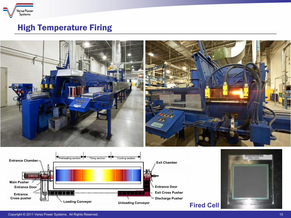
Co-firing is possible but varying shrinkage rates make it challenging Low volume production tends to use batch furnaces, continuous
furnaces are available for high volume firing
Copyright © 2011 Versa Power Systems. All Rights Reserved. 15
Loading Conveyor Unloading Conveyor
Exit Chamber
EntranceCross pusher
Entrance Chamber
Main PusherEntrance Door Entrance Door
Exit Cross Pusher
Discharge Pusher
Fired Cell
High Temperature Firing
Copyright © 2011 Versa Power Systems. All Rights Reserved. 16
Common Metallic Manufacturing Steps
Metallic fabrication processes are well established and not unique to SOFC manufacturing– Stamping, punching, rolling, brazing, welding– Powder metallurgy, casting
In some instances, coatings are applied to metallic stack components to improve oxidation characteristics
Copyright © 2011 Versa Power Systems. All Rights Reserved. 17
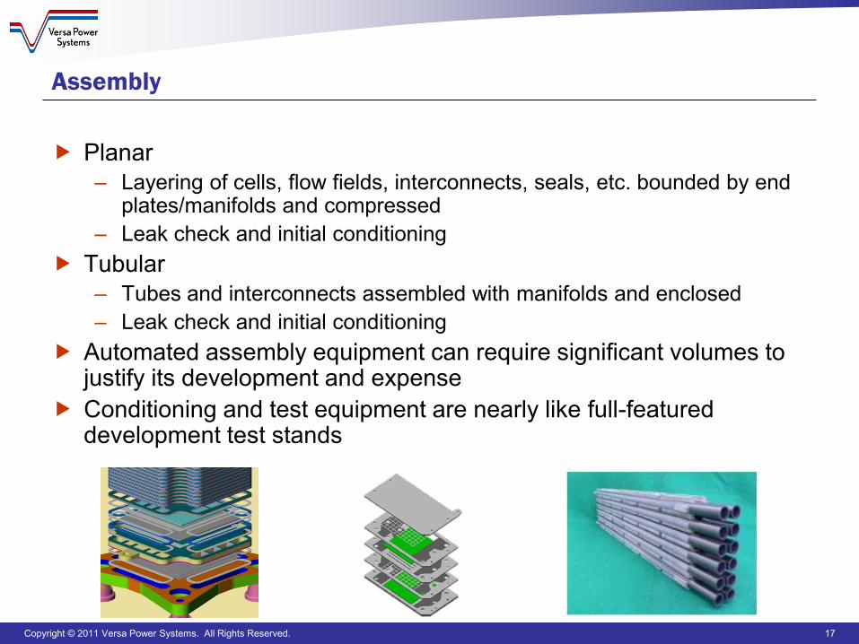
Assembly
Planar– Layering of cells, flow fields, interconnects, seals, etc. bounded by end
plates/manifolds and compressed– Leak check and initial conditioning
Tubular– Tubes and interconnects assembled with manifolds and enclosed– Leak check and initial conditioning
Automated assembly equipment can require significant volumes to justify its development and expense
Conditioning and test equipment are nearly like full-featured development test stands
Copyright © 2011 Versa Power Systems. All Rights Reserved. 18
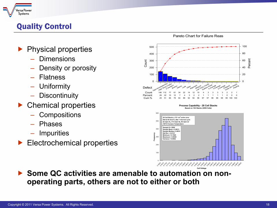
Quality Control
Physical properties – Dimensions– Density or porosity– Flatness– Uniformity– Discontinuity
Chemical properties– Compositions– Phases– Impurities
Electrochemical properties
Some QC activities are amenable to automation on non-operating parts, others are not to either or both
Peeling
Voids (Air Holes)
Chipped
Z Average
Y Average
X Average
Surface Flaws
Low Temp Cracks
Misprint
AlignmentOther
LeakDebris
BrokenZ Variation
High Temp Cracks
Tape Inconsistencies
1 2 2 3 3 3 3 4 10 12 14 22 34 61 77112146 0 0 0 1 1 1 1 1 2 2 3 4 712152229
100100 99 99 98 98 97 97 96 94 92 89 84 78 66 51 29
500
400
300
200
100
0
100
80
60
40
20
0
DefectCount
PercentCum %
Perc
ent
Coun
t
Pareto Chart for Failure Reas
Process Capability - 28 Cell StacksBased on 102 Stacks (2856 Cells)
0
100
200
300
400
500
600
0.762
5
0.767
5
0.772
5
0.777
5
0.782
5
0.787
5
0.792
5
0.797
5
0.802
5
0.807
5
0.812
5
0.817
5
0.822
5
0.827
5
0.832
5
0.837
5
0.842
5
0.847
5
0.852
5
0.857
5
0.862
5
0.867
5
0.872
5
0.877
5
0.882
5
0.887
5
0.892
5
Cell Voltage
Freq
uenc
y
28 Cell Stacks x 121 cm2 active area60A (0.50 A/cm2), after 1 thermal cycle42 slpm H2, 37.8 slpm N2, 84 slpm air725°C Furnace Temperature
Sample N = 2856Sample Mean = 0.8613Sample Median= 0.8633Std Dev = 0.0137Minimum = 0.7600Maximum = 0.8949Variance = 0.0002
Copyright © 2011 Versa Power Systems. All Rights Reserved. 19
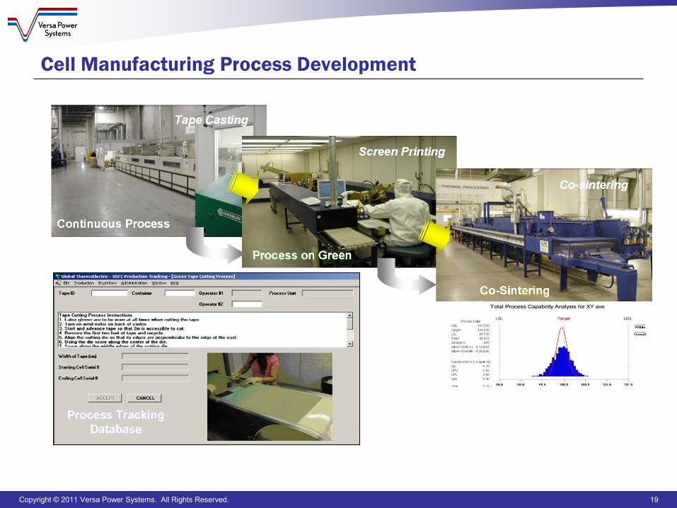
Cell Manufacturing Process Development
Copyright © 2011 Versa Power Systems. All Rights Reserved. 20
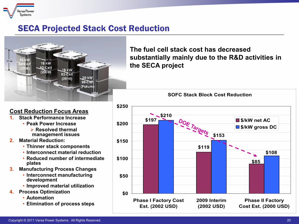
SECA Projected Stack Cost Reduction
Cost Reduction Focus Areas1. Stack Performance Increase
• Peak Power Increase Resolved thermal management issues
2. Material Reduction:• Thinner stack components• Interconnect material reduction• Reduced number of intermediate
plates3. Manufacturing Process Changes
• Interconnect manufacturing development
• Improved material utilization4. Process Optimization
• Automation• Elimination of process steps
SOFC Stack Block Cost Reduction
$197
$119
$210
$153
$85
$108
$0
$50
$100
$150
$200
$250
Phase I Factory CostEst. (2002 USD)
2009 Interim(2002 USD)
Phase II FactoryCost Est. (2000 USD)
$/kW net AC$/kW gross DC
The fuel cell stack cost has decreased substantially mainly due to the R&D activities in the SECA project
Copyright © 2011 Versa Power Systems. All Rights Reserved. 21
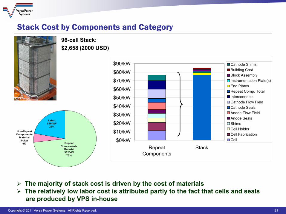
Stack Cost by Components and Category
$0/kW
$10/kW
$20/kW
$30/kW
$40/kW
$50/kW
$60/kW
$70/kW
$80/kW
$90/kW
RepeatComponents
Stack
Cathode ShimsBuilding CostBlock AssemblyInstrumentation Plate(s)End PlatesRepeat Comp. TotalInterconnectsCathode Flow FieldCathode SealsAnode Flow FieldAnode SealsShimsCell HolderCell FabricationCell
The majority of stack cost is driven by the cost of materials The relatively low labor cost is attributed partly to the fact that cells and seals
are produced by VPS in-house
96-cell Stack: $2,658 (2000 USD)
Labor$19/kW
22%
Non-Repeat Components
Material$4/kW
5% Repeat Components
Material$62/kW
73%
Copyright © 2011 Versa Power Systems. All Rights Reserved. 22
Manufacturing Automation Strategies
Manual operation– Production volumes from 5 MW to 25 MW– Use manual equipment with longer cycle times and smaller batch size
Semi-automatic operation– Production volumes from 25 MW to ~100 MW– Use medium size equipment and has partial automation in key stations
Automatic operation– High volume production from ~100 MW to 250 MW– Workstations and material handling system are automated
Copyright © 2011 Versa Power Systems. All Rights Reserved. 23
Cost and Manufacturing Initiatives
Materials– Materials reduction in cell and stack– Low cost materials– Interconnect coating
Fabrication and assembly– Cell co-sintering– Sealing technology
Quality control and testing– On-line QA/QC with real time feedback– Stack conditioning
Copyright © 2011 Versa Power Systems. All Rights Reserved. 24
Questions?
Portions of this material are based upon work supported by theDepartment of Energy under Award Number
DE-FC26-04NT41837
This report was prepared as an account of work sponsored by an agency of the United States Government. Neither the United States Government nor any agency thereof, nor any of their employees, makes any warranty, express or implied, or assumes any legal liability or responsibility for the accuracy, completeness, or usefulness of any information, apparatus, product, or process disclosed, or represents that its use would not infringe privately owned
rights. Reference herein to any specific commercial product, process, or service by trade name, trademark, manufacturer, or otherwise does not necessarily constitute or imply its endorsement, recommendation, or favoring by the United States Government or any agency thereof. The views and
opinions of authors expressed herein do not necessarily state or reflect those of the United States Government or any agency thereof.