solder creep-fatigue interactions with flexible leaded … · solder creep-fatigue interactions...
TRANSCRIPT

R. G. Ross, Jr.
L. C. Wen
G. R. Mon
E. Jetter
Jet Propulsion Laboratory, Pasadena, CA 91109
Solder Creep-Fatigue Interactions With Flexible Leaded Parts With flexible leaded parts, the solder-joint failure process involves a complex in- terplay of creep and fatigue mechanisms. To better understand the role of creep in typical multi-hour cyclic loading conditions, a specialized non-linear finite-element creep simulation computer program has been formulated. The numerical algorithm includes the complete part-lead-solder-P WB system, accounting for strain-rate de- pendence of creep on applied stress and temperature, and the role of the part-lead dimensions and fi’exibihty that determine the total creep deflection (solder strain range) during stress relaxation. The computer program has been used to explore the effects of various solder creepfatigue parameters such as lead height and stiff- ness, thermal-cycle test profile, and part/board differential thermal expansion prop erties. One of the most interesting findings is the strong presence of unidirectional creep-ratcheting that occurs during thermal cycling due to temperature dominated strain-rate effects. To corroborate the solder fatigue model predictions, a number of carefully controlled thermal-cycle tests have been conducted using special bi- metallic test boards.
Introduction For most spacecraft electronics it is not a single high stress
event that breaks a component solder joint; rather it is repeated or prolonged load applications that result in fatigue or creep failure of the solder. Figure 1 presents representative fatigue- life data for 63-37 Sn-Pb solder and illustrates the typical dependency between cycles-to-failure and the total peak-to- peak strain range per cycle. In most electronic packaging ap- plications, the principal strain in solder joints is caused by differential expansion between the part and its mounting en- vironment due to changes in temperature (thermal cycles) and/ or due to temperature gradients between the part and the board.
The function of strain relief elements-such as the flexible metals leads of the electronic components-is to lower the differential-expansion induced loads (stresses) on the solder joints to levels below the solder yield strength, thus minimizing the generation of plastic strain. Unfortunately, under typical multi-hour loading conditions the solder joints can still be expected to undergo modest levels of strain due to creep of the solder in response to the applied elastic forces from the strain relief elements. This creep-induced strain has the same damaging effect as more immediately induced plastic strain, and must be summed with the plastic strain to achieve the total plastic strain range that is correlated with fatigue life in Fig. 1.
Because of creep effects, the total strain range during any given loading cycle can be a strong function of solder tem- perature, the loading time per cycle, the applied solder stress,
Contributed by the Electrical and Electronic Packaging Divsion and presented at the Winter Annual Meeting, Atlanta, Ga. December 1-6, 1991 of THE AMER- ICAN SXIEIY OF MECHANICAL ENGINEERS. Manuscript received by the EEPD August 1991. Paper No. 91-WA/EEP-27.
and the spring constant of the strain relief elements; in ad- dition, solder metallurgical state including grain size and aging condition also influence the solder creep rate. Figure 2 illus- trates the strong dependence of solder strain rate (creep rate) on the temperature of the solder and the stress applied to the solder by the electronic part-board system.
Although extensive research in recent years has led to an increasingly mature understanding of the creep-fatigue prop- erties of solder as an engineering material, much less headway has been made in quantifying solder creep-fatigue behavior at the electronic package systems level. The objective of the on-
200
100
i
= 10
2
:
EJ
2 1
CYCLES TO FAUJRE
Fig. 1 Coffin-Manson curves fitted to typical eutectic Sn-Pb solder fatigue data from Aldrich (1970), Wild (1975), and Solomon (1990)
Journal of Electronic Packaging JUNE 1992, Vol. 114 I185
APPLE0 STRESS. MPa
-1 10
-2 10
r r -a-
H
10
t 10 -4-
d
E 'O -5-
10 4
‘7 10 t
41 I”...l 10 0.05 0.1 0.2 0.5 1 2’ 5”
APPUED sT!AEss, ksi
Fig. 2 Eutectic Sn-Pb solder creep strain rate versus applied stress and temperature (from Cline and Alden, 1967)
going study described here is to explore and understand the complex systems-level creep-fatigue interactions involved in electronic part solder joints, and in particular to understand the key solder-joint structural configuration and environmen- tal stress dependencies. Important issues include the effects of component lead flexibility, solder joint geometry, operating temperature, thermal cycling depth, and cyclic frequency of loading. Understanding these issues is important to both achieving robust electronic packaging designs that meet the end-use requirements, and to defining and interpreting appro- priate testing procedures for hardware qualification.
The study reported here involves two major elements: 1) the development and use of a specialized non-linear finite-element creep simulation computer program for solder systems anal- ysis, and 2) the development and use of special bi-metallic test boards to conduct accelerated thermal-cycle tests to corro- borate the analytical results.
Creep Simulation Modeling In studying the durability of solder joints, many important
parameters such as dependence on component leads and inter- connection geometry, cyclic frequency dependence, and tem- perature dependence, have been shown to be structural-system issues as much as they are materials issues (Ross et al., 1991).
With this premise, the approach of the present study has been to utilize a special purpose nonlinear finite-element elas- tic-plastic-creep simulation program to study the behavior of solder joints in the context of the complete part-lead-solder- PWB system. Given a time history of environmental loading (e.g., part temperature versus time) the JPL-developed pro- gram computes the resulting strain in each element of the solder joint as a function of time. Varying the system geometry, cycle rate, thermal-cycle depth, or any of a wide variety of param- eters, allows the resulting effects on solder strain history to be observed directly.
In operation, the program divides the time response of the solder joint into thousands of tiny time increments; for each time increment the solder’s incremental plastic strain response is computed based on the existing stress in the solder, the solder’s temperature, and the state of externally applied loads. The program starts each time increment by computing the instantaneous stress in each solder element using a special- purpose finite element elastic structural model of the computer part-lead-solder-PWB system. The forcing function for the stresses is the instantaneous geometry of the package system including previously accrued plastic deformation of the solder elements and lead deflections applied externally by thermal- cycle differential expansions or mechanical (isothermal) cy- cling. Following computation of the stress, the program uses constitutive equations for solder (a numerical expression of
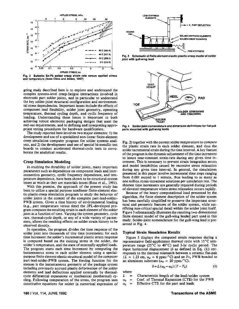
+ X. PAfiT LEFLECl’fON
Fig. 3 Schematic of finite element elastic-plastic-creep model of solder joint with gull-wing lead
PAD
SOLDER STRESSING AND CRACKING
Fig. 4 Solder.joint nomenclature and dimension definitions for flat-pak parts mounted with gull-wing leads
Fig. 2) together with the current solder temperature to compute the plastic strain rate in each solder element, and thus the solder incremental strain during the time interval. A key feature of the program is the dynamic adjustment of the time increment to insure near-constant strain-rate during any given time in- crement. This is necessary to prevent strain integration errors and model instabilities caused by excessive stress relaxation during any given time interval. In general, the simulations presented in this paper involve incremental time steps ranging from 0.001 second to 1 minute, thus leading to as many as one million strain-increment solutions per simulation run. The shortest time increments are generally required during periods of elevated temperature where stress relaxation occurs rapidly.
Because of the heavy computational load presented by the algorithm, the finite element description of the solder system has been carefully simplified to preserve the important struc- tural and geometric features of the solder system, while sac- rificing non-critical spatial detail within the solder joint itself. Figure 3 schematically illustrates the resulting two-dimensional finite element model of the gull-wing leaded part used in this study. Solder-joint nomenclature for the gull-wing lead is pre- sented in Fig. 4.
Typical Strain Simulation Results Figure 5 displays the computed strain response during a
representative field-application thermal cycle with 15°C tem- perature range (25’C to 40°C) and 3-hr cyclic period. The input horizontal displacement (6 as defined in Eq. (1)) cor- responds to the thermal mismatch between a ceramic flat-pak (L = 1.23 cm, cu, = 6 ppm/“C) and an Fr4 PWB bonded to an aluminum substrate (CQ = 20 ppm/‘C).
6=L(ap-ab)(T-T(J (1) where L = Characteristic length of the lead/solder system (Yb = Coef. of Thermal Expansion (CTE) for the PWB ap = Effective CTE for the part and leads
Transactions of the &E 186 I Vol. 114, JUNE 1992

llME mill
Fig. 5 Example flat-pak lead displacement and solder strain response to 15*C thermal cycle with 3.hour period
3
2
il
0
-1 0 200 400 em so0 IOW
CYCLES
Fig. 6 Thermal cycle strain response showing dependence of creep ratcheting on lead height
To = Reference (no strain) temperature T = Instantaneous cyclic temperature
The reference temperature To is taken as 325°C and the displacement variation, shown at the bottom of Fig. 5, cor- responds to a * 7.5 “C temperature swing over the three-hour cycle. The first two cycles of computed strain variation at the solder joint heel and toe are shown in the top of Fig. 5 for a typical 20-mil lead height and 7-mil lead thickness. The max- imum strain range (about 0.17 percent) occurs as a normal- to-the-board tension-compression at the heel, while the toe undergoes much less strain.
An an example of the use of the program to examine elec- tronic packaging systems effects, Fig. 6 displays the straining at the heel for the same flat-pak part used in Fig. 5, but bent with three different lead heights. Lead stiffness rapidly de- creases with increasing lead height for a given lead thickness, thus reducing the solder stress and resulting strain rate. As can be seen, lead stiffness plays a key role in solder joint integrity. For the lo-, 20-, and 30-mil lead heights, the computed cyclic strain ranges are 0.62 percent, 0.16 percent, and 0.051 percent, respectively.
Creep Ratcheting Perhaps the most important finding from the solder strain
simulation results illustrated in Fig. 6 is the existence of pro- gressive strain drift or “creep ratcheting” that accompanies the alternating fatigue component in long-term thermal cy- cling. In this example, this progressive strain drift is 2.5, 0.5, and 0.04 percent, respectively, after 1000 thermal cycles. An important part of the ongoing research at JPL has been val- idating this observed phenomenon and understanding its im- plications on electronic package design and testing. In this
Fig. 7 Creep ratchet visible in thermal-cycle strain response as com- pared with isothermal mechanical cycling
30
ia
TOE
26
24
=z J
CYCLES
Fig. 6 Creep ratcheting apparent in heel and toe strain response to 13SC thermal cycling
paper we refer to the phenomenon as “creep ratcheting” in recognition of its ratchet-like directional dependence, which stems from the strong temperature dependence of creep during different phases of the loading cycle. Creep ratcheting has proven to be real to our satisfaction, and also agrees with the recent observations of other investigators such as Pan (1991).
To further illustrate the observed creep ratcheting phenom- enon, a pair of simulations is presented in Fig. 7, based on the same 20-mil flat-pak used in Fig. 5, but with the displace- ments provided in one case by the 25°C to 40°C thermal cycle, and in the other case by an isothermal mechanical cycle with the same lead displacement and 32.5”C mean temperature. The left side of the figure compares the strain variations in the first five cycles. It can be seen that the shapes and ampli- tudes of the two cases are very similar. However, after 1000 cycles, the mechanically cycled straining remains essentially unchanged and is symmetrical about the neutral position. The thermally cycled straining, on the other hand, has ratcheted- in essence, drifted-an additional 0.6 percent over and above the mechanical cycling component.
The mechanics of creep-ratcheting can be better understood by studying the exaggerated movements occurring in deep tem- perature cycles (- 35°C to 100°C); these are typical of NASA qualification test levels for electronic circuit boards (NASA, 1986).
Figure 8 displays the tension-compression strain variations occurring between the 90th and 100th deep thermal cycle (range = 135”C, mean temperature = 32.5-C) as computed at the heel and at the toe for the same lead-solder system used in Fig. 6. The rate of creep ratcheting is considerably larger for the 135°C cycle depth than for the 15°C cycle depth; this can be seen by comparing the data of Figs. 6 and 8. Note that the
Journal of Electronic Packaging JUNE 1992, Vol. 114 I187

Fig. g Comparison of steady state shear stress vs. time for isothermal mechanical cycling and thermal cycling having the identical (shown) displacement
20 B I
10 f
&
0
-10
-2 ’ I 96 69 im
CYCLE6
Fig. 10 Comparison of steady state heel stress versus time for iso- thermal mechanical cycling and thermal cycling having the identical (shown) displacement
tension-compression strains at the heel and toe are out of phase; when the heel fillet is in tension, the toe fillet is in compression, and vice versa. Thus the foot of the lead, which is directly connected to the solder, rocks back and fourth (heel-to-toe) while at the same time, because of the creep ratcheting of the solder, it suffers a bias “drift” in a direction normal to the board-away from the board if (Yb > oP, toward the board is ‘& < “p.
To explore the fundamentals underlying the creep-ratcheting phenomenon, it is useful to examine closely the 135°C thermal- cycle simulation results. Figure 9 shows the computed shear stress variations for this thermal cycle (for ob > oP) overlaid on the corresponding data for isothermal mechanical cycling, i.e., with identical part displacement profiles. It is helpful to first examine the mechanics of the mechanical cycling, and then to contrast them with the observed differences for ther- mal-cycling.
Strain Development During Isothermal Mechanical Cy- cling. During the expansion phase of the isothermal me- chanical cycle, there is a positive displacement of the part lead in the +x direction (see Fig. 3), and a resulting horizontal force applied to the solder fillet in the +x direction. This force generates both horizontal shear stresses and vertical tension- compression stresses within the solder. The corresponding shear stress in the solder increases to a maximum as the displacement proceeds from point “a” to point “b” (Fig. 9). During the dwell time (“b” to “c”), the stress relaxes due to creep until the displacement direction reverses (“c” to “d”) and ultimately achieves a maximum displacement in the -x direction (point “e”) just before the stress again undergoes creep relaxation during the dwell period. In essence, once a steady state con- dition is achieved, the shear stress variation during isothermal mechanical cycling is symmetrical relative to the neutral po- sition and it closely tracks the displacement profile.
188 I Vol. 114, JUNE 1992 Transactions of the ASME
-2 0 2 4 6 6 10
CVCLES
Fig. 11 Transient shear stress and strain response to isothermal me- chanical cycling (bottom) and thermal cycling (top) with identical dis- placement
The corresponding tension-compression heel stress variation in isothermal mechanical cycling is also symmetrical about the zero strain axis, as shown in Fig. 10. The heel is under compres- sion, while the toe is under tension when the part displacement is positive. These stresses relax during the dwell time and re- verse their sense when the part displacement changes direction.
Strain Development During Thermal Cycling. If the part displacements arise from differential thermal expansion-con- traction during temperature cycling, the dynamics are quite different from those for isothermal mechanical cycling; this is because solder creeps much more rapidly during the higher- temperature portion of the cycle than during the lower-tem- perature portion, in accordance with Fig. 2. The difference between isothermal mechanical cycling and temperature cy- cling manifests in the very first cycle. If the thermal cycle starts with cooling, a net initial displacement in the -x direction, the solder is quite creep-resistance because of the low tem- perature; the resulting shear strain is therefore very limited and most of the would-be solder displacement is absorbed by lead deflection. As the solder temperature increases during the warm-up phase of the cycle, it more readily deforms in response to the force exerted by the deflected lead, and produces a large shear strain in the +x direction (almost 3 percent in the first cycle as shown in Fig. 11). In the subsequent cooling phase the solder again loses its ductility and yields only slightly in the reverse (-x) direction. After a number of cycles the lead achieves a deflection bias in the +x direction that provides a greater force in the yielding direction during the cold half cycle, and a reduced force during the hot half cycle. This equilibrium force offset is that required to provide equal horizontal creep in plus and minus shear directions during each cycle; at this point the shear strain cycling becomes symmetrical, and this symmetry is a function of the lead stiffness and lead-solder characteristics.
In response to this horizontal lead deflection offset that develops to maintain shear strain symmetry, out of phase ten- sion-compression forces are developed normal to the board favoring tension creep in the solder joint for the case ob > c+, and compression creep in the solder joint for the case c&‘b < op. As a result, the tension-compression stress at the heel during the cooldown, “c-d-e”, is significantly larger than the same stress during the warmup, “f-a-b”, as shown in Figs. 10 and 12. Consequently, a resultant creep-ratcheting strain in the tension-compression direction is generated each cycle. Since normal-to-the-board tension drift has no means of generating a self-arresting force, it continues ratcheting at a constant rate as illustrated in Fig. 6. For the opposite case ((Yb < c+), where normal-to-the board ratcheting occurs in the compression di-

0. I I 0
c -1 - a
b a - -10
-2' I I -10 0 10 20 30 40
EJWN%
Fig. 12 Heel stress-strain hysteresis loops for thermallv and mcnhan. ically strained solder joint
-.--.., -.-- . ..--..-..
CTEpart ’ CT’Goard CTEpart < C’Roard
CREEP-RATCHETS DOWN CREEP-RATCHETS VP
Fig. 13 Visualization of creep-rachet induced lead deflections and ratchet directions for parts with gull-wing leads
rection, ratcheting will self arrest when the lead bottoms out against the solder pad. These creep-ratchet induced lead de- flections and ratchet directions are schematically illustrated in Fig. 13.
Damage Prediction with Combined Creep Ratcheting and Fatigue
Before further examing the implications of the strain sim- ulation results it is useful to develop an analysis structure for comparing the damage caused by creep-ratcheting strain rel- ative to that caused by cyclic fatigue strain.
Although there are many possible approaches to assessing the interactive damage contributions of creep rupture and fa- tigue, the most straightforward technique is to use Miner’s Rule, which additively accumulates the individual fractional damage rates as follows:
where cp= 1= I-= N= N/ =
(o=nN/r+N/N,=N(n/T+l/N,) (2)
fraction of useful service life consumed creep ratchet strain per cycle strain limit for creep rupture number of cycles of applied stress number of cycles to fatigue failure
If we use Manson’s (1965) fatigue relationship as embodied in Fig. 1 to predict NJ, then
NfAe = C (3) where
N, = number of cycles to fatigue failure AE = cyclic plastic strain range P = 0.46 (from curve slope in Fig. 1) C= 0.80 (for 50 percent solder failure limit in Fig. 1)
To estimate the strain rupture limit (T), we again follow the
Table 1. Comparison of computed creep-fatigue damage and predicted life for solder joints with different lead heights and thermal-cycle depths
Lead Height,
mils (mm)
Cycle Depth
ec,
Creep Rachet
Range Strain, 0
Ae, (%) per 1000
H IO II 15 1 0.512 1 2.50 1 2.9E4 1 49 1 1 1
I/ C.25)
II 135 1 4.630 1 683 1 152 I 69 I 195 1
(Z)
t (.%)
Cycle period = 180 minutes N = Sewice Me, cycles 9 = Percent damage due to creep racheting x = Acceleration factor
lead of Manson, who in the development of his strain-cycle fatigue relationship (Eq. (3)), viewed the tensile test as a cyclic fatigue failure at l/4 cycle. In similar fashion the strain range at the l/Ccycle point on the Coffin-Manson plot can be taken as a rough estimate of the creep extension limit, i.e.,
I’=C/(O.25)’
Combining Eqs. (2), (3) and (4) gives (4)
$=Mv(O.25)‘/C+ (AdC)“‘] (5) Equation (5) can also be used to describe the acceleration of a particular test condition (1) over that of another condition (2) by noting that the acceleration ratio K is given by the ratio NJN,, where Nr is the number of environmental stress cycles at condition (1) required to yield the same damage as N2 cycles at environmental stress condition (2), i.e., K = N2/Nl for 4i = &; thus,
65)
Strain Damage Estimates for Combined Creep Ratch- eting and Fatigue
Returning to the above examples, Eq. (5) can now be used to obtain an estimate of the relative importance of the observed strain ratcheting and cyclic fatigue.
With the modest 15”C-cycle depth used in Fig. 6, recall that the creep ratcheting drifts were 2.5,0.5, and 0.04 percent after 1000 cycles for the lo-, 20-, and 30-mil lead heights, respec- tively, and the corresponding cyclic fatigue strain range per cycle was 0.62, 0.16, and 0.051 percent, respectively. When these data and the parameters from Fig. 1 are entered in Eq. (5), the creep-ratchet and fatigue damage are both found to be quite small, but about equal in level.
Continuing this analysis for the simulation results of the deep 135°C thermal cycles provides the data assembled in Table 1. In the cases presented in Table 1, the dominating failure mechanisms are extension-compression low-cycle fatigue and creep at the heel (or toe) of the solder joints. Note that creep- ratcheting represents over 50 percent of the damage in most of the cases.
For completeness, it is also important to note that under a “worst case” combination of stiff lead, large temperature cy- cling range, and large mismatch in CTEs, different creep and fatigue mechanisms, those acting in the shear direction, can
Journal of Electronic Packaging JUNE 1992, Vol. 114 I189

40 - HEEL -e---em m . . . . . . . . . . . . . ww
-10 1 I 0 2 4 6 6 10
CYCLES
Fig. 14 Dominance of shear strain with flat-pak with stiff lO.mil lead height mounted to type ALES test fixture for accelerated thermal-cycle testing
dominate solder joint damage accumulation (Ross et al., 1991). To illustrate this, consider a IO-mil lead height flat-pak as- sembly on a thermal expansion fixture subjected to a - 25°C to + 100°C thermal-cycle environment with a 3-hour cycle period. For this case the extension-compression cyclic strain range, shown in Fig. 14, is approximately 15 percent, and the creep ratchet in the normal-to-the-board direction is 15 percent per 100 cycles. However, the dominating contributor to failure is neither of these normal-to-the-board mechanisms. The com- puted parallel-to-the-board shear strain is as much as 30 per- cent, and may produce failure in less than 10 cycles, while the damage contribution from extension-compression fatigue and creep rupture is less than 10 percent. Because the dominating failure mechanisms can be significantly different for different thermal-cycle and mechanical-loading environments, care must be exercised in extrapolating test results from one environment to another. This is particularly true for the process of devel- oping and understanding the results of accelerated testing.
Experimental Testing of Creep-Fatigue Interactions It can be seen from the previous discussion that creep-fatigue
interaction is far more complicated than generally anticipated. Just as both temperature range and lead stiffness can signif- icantly influence the relative roles of creep ratcheting and cyclic fatigue, so also can other operational parameters be influential. In particular, the relative direction of creep ratcheting can be extremely important. If creep ratcheting is in the compression direction, the lead will bottom out on the PWB solder pad and the creep will self-arrest. On the other hand, if the creep ratcheting is in the tension direction, the lead may gradually pull out of the solder joint until complete separation occurs.
In order to experimentally investigate the system aspects of combined creep-fatigue interactions, special bi-metallic test fixtures, Fig. 15, were developed. A particularly useful feature of the bi-metallic fixtures is the ability of the relative position of the two metal plates (one aluminum with CTE = 23 ppm/ “C, the other a 400-series stainless steel with CTE = 9 ppm/ “C) to be reversed; this provides a method to evaluate the level and direction of creep ratcheting. When the stainless steel plate is placed on top of the aluminum, the assembly simulates a low-CTE part mounted to a high-CTE board-this correlates with tensile creep ratcheting away from the solder pads, and the possibility of ultimate tensile failure. If the plates are re- versed, the assembly simulates a high-CTE part mounted to a low-CTE board, and the creep ratcheting is in compression, and therefore self arresting against the solder pads.
In order to demonstrate the effect of creep ratcheting, and to validate the service life prediction methodology, a special experiment was conducted with gullwing-leaded flat-paks sol- dered on the two types of fixtures-the type %/AL (Stainless
Fig. 15 Bimetallic test fixture for accelerated thermal-cycle testing
Fig. 16 Strains and displacements versus time for flat-paks with SO. mil (0.76 mm) lead height mounted to indicated fixtures and exposed to thermal cycling from - 25T to + 100°C
Steel on Aluminum) and the type AL/SS (Aluminum on Stain- less Steel). To avoid excessive shear stressing, compliant 5-mil thick by 30-mil high leads were employed in this experiment. The temperature cycling was conducted from - 25°C to + 100°C using the 3-hr cycle derived for spacecraft electronics qualification (Ross, 1991).
Analytical Predictions. Before starting the test, the finite element strain simulation program was used in conjunction with the failure prediction methodology to analyze and predict the expected outcome. Figure 16 illustrates the shear and nor- mal heel strains computed using the creep-fatigue simulation program for the 90th through the 200th cycle of the - 25°C to + 100°C thermal-cycle exposure. Note that the lead dis- placement for the two assemblies move out of phase with each other and their magnitudes are not identical; this is because, even though the contribution of the chip/lead CTE in both cases is the same, the contributions of the bi-metal CTEs are not.
The curves above the zero-strain axis in Fig. 16 show the strain developed in the solder joints on the SS/AL fixture. The dominating strains are seen to be combined cyclic and creep- ratchet tension-compression strain at the solder joint heel, i.e., the toe strains are typically less dominant than the heel strains. One notices that the cyclic heel strain range remains at a con- stant level of 5.54 percent throughout the testing, i.e., the damage due to low cycle tension-compression fatigue is ac- cruing at a constant rate. Similarly, the creep ratcheting rate for normal strain at the heel is also progressing at a constant rate of 28 percent per 100 cycles. The shear strain, on the other hand, behaves quite differently. The shear cycle strain range is too small (less than 0.2 percent) to account for significant damage contribution, and although the shear creep-ratchet bias is very significant in the early stages of cycling, it reaches a plateau at around + 25 percent, and grows very little thereafter. After 100 cycles, the damage on the solder joints primarily derives from a combination of tension-compression fatigue and creep ratcheting, with a fixed shear creep-ratchet contri- bution. Based on Eq. (5), the expected cycles-to-failure due to
190 I Vol. 114, JUNE 1992 Transactions of the ASME

mained intact for hundreds of additional cycles. Figure 19presents a cross-section of a representative solder joint on theAL/SS fixture after 775 cycles. Although crack propagation
combined creep ratcheting and fatigue is 210 cycles. In thiscase, the failure is dominated by cyclic fatigue, although creepratcheting contributes a significant 37 percent to the overalldamage.
In contrast, the same solder joints on an AL/SS fixture showa completely different correlation (bottom curves in Fig. 16).For this case, the tension-compression strains creep ratchet inthe negative (compression) direction, and the shear strain isalso in the opposite (negative) direction from that of the SS/AL fixture. The cyclic shear strain range is only 0.08 percentwith a quasi-static creep ratchet displacement of approximately17 percent. The heel cyclic tension-compression strain rangeis 3.45 percent, and the corresponding creep-ratchetingcompression strain is 10 percent per 100 cycles. Unlike tensilecreep ratcheting, compressive creep ratcheting contributes todamage, but is self arresting; consequently, the principal mecha-nism contributing to failure is cyclic fatigue, and the expectedfatigue endurance for a 50 percent failure criterion is approxi-mately 1000 cycles. This is five times that of the inverted SS/AL board.
Thermal Cycle Test Results. After approximately 100 ther-mal cycles, the test fixtures were removed from the test chamberand examined microscopically. No solder joint failures wereevident, but stress lines (fine microcracks) were observed inthe fillets as were small cracks at the heels. However, therewere no significant visual indications to reflect the analyticalprediction that the solder joints on the SS/AL fixture shouldhave a service life only 20 percent of those on the AL/SSfixture.
Again, after 164 cycles the fixtures were removed from thetest chamber and examined. The solder joints on the SS/ALfixture showed some crack propagation starting from the heel,while the solder joints on the AL/SS fixture remained in es-sentially the same state they were at after 100 cycles. Afteraround 200 cycles, the solder cracks on the SWAL fixturereached their rupture limit and began to fail catastrophically.Figure 17 shows the lifted leads as they appeared at 214 cycles,while Fig. 18 shows a cross-section of two of these leads, onelifted and one still surviving. The lead lifting and number ofcycles to failure are in good agreement with the tensile creep-ratcheting-fatigue failure predicted above and illustrated inthe right side of Fig. 13.
Also as predicted, the solder joints on the AL/SS fixtureshowed no significant crack growth after 200 cycles, and re-
Fig 17 Failure of solder joints on type SS/AL fixcture after 214 thermalcycles from -25°C to + 100°C
Journal of Electronic Packaging JUNE 1992, Vol. 114 / 191
Fig. 19 Cross-section of solder joint on AL/SS fixture displaying compres-sive creep ratcheting after 775 cycles
Fig. 18 Cross-section of solder joints on SSlAL fixture displaying tensilefailure after 214 cycles

has progressed from the heel to the middle of the foot, the toe region is solidly attached and appears compressed toward the board. This agrees with the expectation of negative (com- pressive) creep-ratcheting as shown in the left side of Fig. 13.
In conclusion, the experimental evidence supports the an- alytical simulation and life-prediction methodology, and sug- gests that creep ratcheting is an important system’s level damage mechanism that should be carefully addressed in the design and testing of solder joints in electronic assemblies.
Discussion and Concluding Summary The present investigation has focused on demonstrating the
complex failure processes present with creep-fatigue interac- tion at the electronic package system’s level. The results in- dicate that the interplay between the mechanisms is extremely intricate. For flat-paks having gull-wing leads in thermal cy- cling environments, creep and fatigue act simultaneously and jointly on the solder joint. The interaction produces a heel-to- toe rocking that causes the lead to lift out of, or plow into, the solder fillet, a phenomenon we have dubbed “creep ratch- eting.” This phenomenon was not found in simulations of isothermal mechanical cycling.
Lead compliance has been shown to play a profound role in solder joint response to thermal cycling. Solder joints with leads having different compliance are likely to lead to different damage mechanisms in the same test environment. For compliant leads, solder-joint failure in a thermal cycling environment is generally caused by a combination of tension- compression cyclic fatigue and creep ratcheting at the heel. However, for a very stiff lead the dominant damage mechanism can be cyclic shear fatigue.
The relative importance of each damage mechanism can change as the test progresses. Initial shear creep ratcheting, if it does not exceed the rupture limit, is self-arresting after a few cycles. This damage mechanism can thus produce an early appearance of cracks, but does not necessarily result in crack propagation. Instead, as more and more cycles accumulate,
the dominant damage mechanism can become tensile creep ratcheting and fatigue, eventually resulting in failure. An im- portant observation is that conclusions based upon early test inspections, when one failure mechanism is predominant, may lead to erroneous projections of failure at later times; this is because damage accumulation rates change as different mech- anisms become predominant.
Acknowledgment The work in this paper was carried out by the Jet Propulsion
Laboratory, California Institute of Technology, under con- tract with the National Aeronautics and Space Administration.
References Aldrich, J. W., and Avery, D. H., 1970, “Alternating Strain Behavior of a
Superplastic Metal,” (Ntrofine Grain Metals, Proceedings of the 16th Sagamore Army Material Research Conference, Aug., Syracuse University Press, pp. 397- 416.
Cline, H. E., and Alden, T. H., 1967, “Rate Sensitive Deformation in Tin- Lead Alloy,” Trum. AIME, Vol. 239, pp. 710-714.
Mason, S. S., 1960, “Effect of Mean Stress and Strain on Cyclic Life,” Muchine Design, Aug., pp. 129-135.
Mason, S. S., 1965, “Fatigue: A Complex Subject - Some Simple Approx- imations,” Engineering Mechanics, Vol. 5, pp. 193-226.
NASA, 1986, “Requirements for Soldered Electrical Connections,” NHB 5300.4 (3A-l), revalidation date June.
Pan, T-Y., 1991, “Thermal Cycling Induced Plastic Deformation in Solder Joints - Part 1: Accumulated Deformation in Surface Mount Joints,” ASME Jooaulu OF ELECTRONIC PACKAGING, Vol. 113, Mar., pp. 8-15.
Ross, R. G., Jr., 1991, “A Systems Approach to Solder Joint Fatigue in Spacecraft Electronic Packaging,” ASME JOURNAL OF ELECTRONIC PACKAGING, Vol. 113, June, pp. 121-128.
Ross, R. G. Jr., et al., 1991, ‘Creep-Fatigue Behavior of Microelectronic Solder Joints,” Proceedings of fhe 1991 MRS Spring Meeting, Anaheim CA, April 30-May 4, 1991.
Solomon, H. D., 1990, “Influence of Temperature on the Fatigue of CC/ PWB Joints,” Journal of the IES. Jan./Feb., pp. 17-25.
Vaynman, S., Fine, M. E., and Jeannotte, D. A., 1991, “Low-cycle Isothermal Fatigue Life of Soldered Materials,” Solder Mechanics, Ed. by Frear, D. R., et al., The Minerals, Metals & Material Society.
Wild, R. N., 1975, “Some Fatigue Properties of Solders and Solder Joints,” IBM Report No. 7AZOLXt481, IBM Federal Systems Division, New York.
192 I Vol. 114, JUNE 1992 Transactions of the ASME