solar electric propulsion (sep) tug power system considerations · 2013-04-10 · solar electric...
TRANSCRIPT

Thomas W. Kerslake, Kristen M. Bury, and Jeffrey S. HojnickiGlenn Research Center, Cleveland, Ohio
Adam M. SajdakGlenn Research Center, Cleveland, Ohio
Robert J. ScheideggerGlenn Research Center, Cleveland, Ohio
Solar Electric Propulsion (SEP) TugPower System Considerations
NASA/TM—2011-217197
December 2011
https://ntrs.nasa.gov/search.jsp?R=20120000910 2020-03-08T15:05:22+00:00Z

NASA STI Program . . . in Profi le
Since its founding, NASA has been dedicated to the advancement of aeronautics and space science. The NASA Scientifi c and Technical Information (STI) program plays a key part in helping NASA maintain this important role.
The NASA STI Program operates under the auspices of the Agency Chief Information Offi cer. It collects, organizes, provides for archiving, and disseminates NASA’s STI. The NASA STI program provides access to the NASA Aeronautics and Space Database and its public interface, the NASA Technical Reports Server, thus providing one of the largest collections of aeronautical and space science STI in the world. Results are published in both non-NASA channels and by NASA in the NASA STI Report Series, which includes the following report types: • TECHNICAL PUBLICATION. Reports of
completed research or a major signifi cant phase of research that present the results of NASA programs and include extensive data or theoretical analysis. Includes compilations of signifi cant scientifi c and technical data and information deemed to be of continuing reference value. NASA counterpart of peer-reviewed formal professional papers but has less stringent limitations on manuscript length and extent of graphic presentations.
• TECHNICAL MEMORANDUM. Scientifi c
and technical fi ndings that are preliminary or of specialized interest, e.g., quick release reports, working papers, and bibliographies that contain minimal annotation. Does not contain extensive analysis.
• CONTRACTOR REPORT. Scientifi c and
technical fi ndings by NASA-sponsored contractors and grantees.
• CONFERENCE PUBLICATION. Collected papers from scientifi c and technical conferences, symposia, seminars, or other meetings sponsored or cosponsored by NASA.
• SPECIAL PUBLICATION. Scientifi c,
technical, or historical information from NASA programs, projects, and missions, often concerned with subjects having substantial public interest.
• TECHNICAL TRANSLATION. English-
language translations of foreign scientifi c and technical material pertinent to NASA’s mission.
Specialized services also include creating custom thesauri, building customized databases, organizing and publishing research results.
For more information about the NASA STI program, see the following:
• Access the NASA STI program home page at http://www.sti.nasa.gov
• E-mail your question via the Internet to help@
sti.nasa.gov • Fax your question to the NASA STI Help Desk
at 443–757–5803 • Telephone the NASA STI Help Desk at 443–757–5802 • Write to:
NASA Center for AeroSpace Information (CASI) 7115 Standard Drive Hanover, MD 21076–1320
Thomas W. Kerslake, Kristen M. Bury, and Jeffrey S. HojnickiGlenn Research Center, Cleveland, Ohio
Adam M. SajdakGlenn Research Center, Cleveland, Ohio
Robert J. ScheideggerGlenn Research Center, Cleveland, Ohio
Solar Electric Propulsion (SEP) TugPower System Considerations
NASA/TM—2011-217197
December 2011
National Aeronautics andSpace Administration
Glenn Research CenterCleveland, Ohio 44135
Prepared for the2011 Space Power Workshopsponsored by the Aerospace CorporationLos Angeles, California, April 18–21, 2011

Available from
NASA Center for Aerospace Information7115 Standard DriveHanover, MD 21076–1320
National Technical Information Service5301 Shawnee Road
Alexandria, VA 22312
Available electronically at http://www.sti.nasa.gov
Trade names and trademarks are used in this report for identifi cation only. Their usage does not constitute an offi cial endorsement, either expressed or implied, by the National Aeronautics and
Space Administration.
Level of Review: This material has been technically reviewed by technical management.
This report is a formal draft or working paper, intended to solicit comments and
ideas from a technical peer group.
This report contains preliminary fi ndings, subject to revision as analysis proceeds.

Solar Electric Propulsion (SEP) Tug Power System Considerations
Thomas W. Kerslake, Kristen M. Bury, and Jeffrey S. Hojnicki
National Aeronautics and Space Administration Glenn Research Center Cleveland, Ohio 44135
Adam M. Sajdak1
National Aeronautics and Space Administration Glenn Research Center Cleveland, Ohio 44135
Robert J. Scheidegger
National Aeronautics and Space Administration Glenn Research Center Cleveland, Ohio 44135
Abstract
Solar electric propulsion (SEP) technology is truly at the “intersection of commercial and military space” as well as the intersection of NASA robotic and human space missions. Building on the use of SEP for geosynchronous spacecraft station keeping, there are numerous potential commercial and military mission applications for SEP stages operating in Earth orbit. At NASA, there is a resurgence of interest in robotic SEP missions for Earth orbit raising applications, 1-AU class heliocentric missions to near Earth objects (NEOs) and SEP spacecraft technology demonstrations. Beyond these nearer term robotic missions, potential future human space flight missions to NEOs with high-power SEP stages are being considered. To enhance or enable this broad class of commercial, military and NASA missions, advancements in the power level and performance of SEP technologies are needed. This presentation will focus on design considerations for the solar photovoltaic array (PVA) and electric power system (EPS) vital to the design and operation of an SEP stage. The engineering and programmatic pros and cons of various PVA and EPS technologies and architectures will be discussed in the context of operating voltage and power levels. The impacts of PVA and EPS design options on the remaining SEP stage subsystem designs, as well as spacecraft operations, will also be discussed.
1Michigan State University, USRP, summer intern.
NASA/TM—2011-217197 1

Solar Electric Propulsion (SEP) Tug
Power System ConsiderationsPower System Considerations
2011 Space Power Workshop
P S t A hit tPower Systems Architecture
April 20, 2011
Presentation by: Tom Kerslake
NASA GRC Co-authors
Tomas W. KerslakeKristen M. BuryJeffrey S. HojnickiJeffrey S. HojnickiAdam M. SajdakRobert J. Scheidegger
Also thanks to many unnamed, but highly appreciated contributors
NASA/TM—2011-217197 1
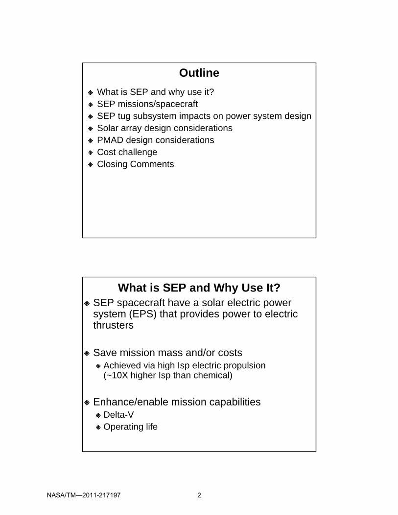
Outline
What is SEP and why use it?SEP missions/spacecraftSEP tug subsystem impacts on power system designSolar array design considerationsPMAD design considerationsCost challengeClosing Comments
What is SEP and Why Use It?SEP spacecraft have a solar electric power system (EPS) that provides power to electric thrusters
Save mission mass and/or costsAchieved via high Isp electric propulsion(~10X higher Isp than chemical)
Enhance/enable mission capabilitiesDelta-VOperating life
NASA/TM—2011-217197 2

1’s kWstation keeping
orbit topping
10’s kW
SEP TechDemo (SFD)
SEP Missions, Spacecraft, and Tugs
Space ScienceEarth and Space Science
Earth Orbit Transfers, GEO Servicing
High delta V100’s kW High delta-VManeuvering
100 s kW
Lunar/MarsHuman Missions
(HEFT)
Solar ArraySolar Array
EPS and SEP Tug Subsystem DesignsAre Highly Interdependent
Impact ofOn
TCS EPS EP Struc-Mech
ACSGNC
Comm StowedConfig
FltOps
Crew
TCS H
EPS M H H H H L H H M
EP H
Struct-Mech H
ACS-GNC H
Comm M
Stowed Config H
Flight Ops H
Crew n/a
H- High, M-Medium, L-Low
NASA/TM—2011-217197 3

SEP Flightmode and Pointing – EPS ImpactsFrom LEO to HEO, must point solar arrays and EP thrusters
With presence of large disturbance torques
1-, 2-DOF gimbal options, roll steering or solar inertial flight modeImplications for solar array, ACS and EP thruster articulation
Outboard Mastthruster Outboard Mastthruster
Open truss canister
Deployable Mast
Root Joint
Outboard joints
Outboard Mast
Inboard Mast
Root Truss
Deployed
palette
Open truss canister
Deployable Mast
Root Joint
Outboard joints
Outboard Mast
Inboard Mast
Root Truss
Deployed
palette
Orbital Mechanics – EPS ImpactsSEP mission solar array / avionics radiation dose dominated (~98%) by trapped protons
Spiraling orbit inclination reduces dose by ~4x (0° to 51.6°)GTO->GEO mission starting arg. of perigee can reduce rad dose by ~6.5X
Place perigee near nodes
Rad dose nearly independent of solar activityEP steering Modes (minimize proton belt transit time)
NASA/TM—2011-217197 4

Space Operations – EPS ImpactsSolar array and PMAD current/voltage sizing will be driven by EP subsystem design and ops
Conventional PPU-based EP subsystemDirect drive DDU-based EP subsystem
Constant voltage (Isp) opsConstant current (flow rate) opsVariable voltage/current (such as Pmax, Max. Thrust, other)
SEP tug operations will drive solar array/gimbal designFast, uniform, robust, reliable solar array deploymentTolerance of large docking/plume loads during RPODHigh deployed strength and stiffness
> ~0.1-g thrust-to-weight for chemical stage burnsAvoid SEP tug and chemical stage controls-structures interactionsLimit solar array deflections
Solar Array Design ConsiderationsConfiguration: number of wings and articulation
Qual and recurring costs (modularity, optics), ground/flight testability Wing stowage, deployment, gimballing complexity, performanceEP plume avoidance (manage sputtering erosion)EP plume avoidance (manage sputtering erosion)
RASC-OASIS Human Mars DRM3.0
ISSISS
Low ELow E
Main BeamMain Beam
ScatteredScattered
NASA/TM—2011-217197 5

Solar Array Design ConsiderationsAmbient and EP induced plasma interactions
Parasitic electron collection (Dominated by EP plasma)Plasma/Vacuum/Sustained Arcing Avoidance/Management
Radiation degradation optimizationg pGoal: Minimum SEP tug cost (or mass) by choice of:
Subsystem designs affecting EPS/EP performance, mission design and solar array design/sizing
Solar Array Design ConsiderationsVoltage selection
Large SEP tug missions optimize w/Hall Thruster Isp ~2000 sec (300-V)300-V class solar array designs consistent with de-rated performance of SOA EEE parts, insulators and gimbal roll-rings/slip rings300-V EPS saves 30-40% mass over 100-V to 160-V EPS SOAAbove considerations make 300-V class direct-drive option attractive300-V solar array technical challenges include higher electron collection current and availability of PMAD electronic parts
Large solar array ground deployment testingKey for risk mitigation/qualification without costly flight testDesigned for 1-g off-loaded, phased, thermal vacuum deploymentDesigned to minimize qualification costs
NASA/TM—2011-217197 6

SEP Tug Primary PMADDistribution Architecture Options (Centralized or Channelized)
Centralized/Channelized Hybrid Option Is Attractive - Good cabling mass/efficiency, modularity, good fault tolerance with cross ties
VoltageVoltageLimitingLimiting
PMAD Design ConsiderationsVoltage level has large impact on PMAD design
Compared to SOA PMAD, 300+ V PMADHigher efficiency systemHigher efficiency systemSignificantly less thermal load (direct-drive)Significant cable mass savings (>60%) due to relatively lower currentsDown conversion needed to feed housekeeping loadsLimited electronic parts selection, especially for high radiation mission: may require wide bandgap electronicsradiation mission: may require wide bandgap electronics
NASA/TM—2011-217197 7

PMAD Design Considerations (con’t)EP operating mode has large impact on PMAD designNon-direct drive
Bus power to thruster PPU power conditioning and boost converterGalvanic isolation decouples source (solar array) and thrusterGood bus power quality and prevents multi-thruster interactionson the busPMAD must deliver predetermined I/V range to PPU
Direct drive offersBus power directly to thrusters via DDUsGood: W/kg, power efficiency, reliability, recurring costBus voltage control primarily tied to EP thruster operationMore work desired in the areas of:
Stability/ops during EP start-up/shut-down transitionsCathode current sharing for multi-thruster opsEffective grounding schemes
PMAD Design Considerations (con’t)Solar array regulator/limiter (Protects from bus high voltage excursions)
Fault tolerance a significant driver for human missionsDesign for thruster-out capability (# failures tolerated?)Cold-spare thrusters or nominally de-rated thrusters
Grounding (negative solar array grounding desired)Grounding (negative solar array grounding desired)Positive solar array ground unacceptable due to arcing/sputtering introduced
600-V rated EEE parts w/derating just sufficient for 300-V class busLimited parts may lead to undesirable board and PMAD box designsMay need to increase to 1200-V rated parts (more limited selection)
EEE parts radiation tolerance (high flux, high energy protons)Leads to high TID and enhanced SEE (MOSFET latch-up, gate rupture)
SEP mission unique combination, high voltage/power/rad dose further limits choice of available parts
May need custom parts development/screening (including SiC parts) and more rad testing (TID and SEE) – all increasing costsMay require more box-level radiation shielding adding significant mass
NASA/TM—2011-217197 8
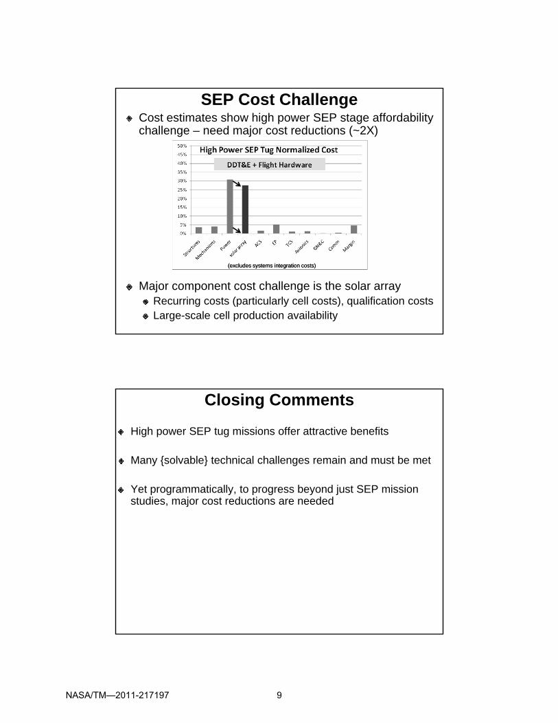
SEP Cost ChallengeCost estimates show high power SEP stage affordability challenge – need major cost reductions (~2X)
Major component cost challenge is the solar arrayRecurring costs (particularly cell costs), qualification costsLarge-scale cell production availability
(excludes systems integration costs)(excludes systems integration costs)
Closing Comments
High power SEP tug missions offer attractive benefits
Many {solvable} technical challenges remain and must be met
Yet programmatically, to progress beyond just SEP mission studies, major cost reductions are needed
NASA/TM—2011-217197 9

Thank YouQuestions?
Appendix Charts
More detailed, back-up informationthat is not part of the
main presentation
NASA/TM—2011-217197 10

Solar Electric Propulsion (SEP) TugPower System Considerations;
*** Back-up Material ***
2011 Space Power Workshop
Power Systems Architecture
April 20, 2011p
Tom Kerslake, Kristen Bury, Jeff Hojnicki,
Adam Sajdak, Bob Scheidegger
List of Abbreviationsa constantArg argumentBOL beginning of lifeComm communicationsConc concentration (optical)DDT&E design, development, test & engineeringDDU direct drive unitDelta-V change in velocity (of spacecraft)DENI d i l ll i id
LEO low earth orbitLVLH local vertical, local horizontal (flight mode)Mech mechanismsMOSFET metal oxide field effect transistorOASIS orbital aggregation & space infrastructure systemsOPS operationsPDU power distribution unitPMAD power management and distributionPmax maximum powerDENI damage equivalent normally incident
DOF degree of freedomDRM design reference missionEEE electrical, electronic, and electromechanicalE-M L1 earth moon Lagrange point 1EOL end of lifeEP electric propulsionEPS electrical power systemg acceleration due to gravityGEO geosynchronous earth orbitGNC guidance, navigation and controlGTO geosynchronous transfer orbit
Pmax maximum powerPPU power processing unitrad radiationRASC revolutionary aerospace systems conceptsRev (orbital) revolutionRPC remote power controllerRPOD rendezvous proximity operations and dockingSEE single event effectsSEP solar electric propulsionSFD SEP Flight DemonstrationSLA Stretch lens array (Entech Technology)SOA state of the artGTO geosynchronous transfer orbit
HEFT human exploration framework teamHEO high earth orbitImp maximum power currentIsp specific impulse (of EP thruster)ISS International Space StationI/V current / voltage
Struct structuresTCS thermal control systemTID total integrated doseV voltage or voltsVmp maximum power voltage
NASA/TM—2011-217197 11

What is SEP and Why Use It?SEP spacecraft have a solar electric power system (EPS) that provides power to electric thrustersS d/ tSave mass and/or costs
Achieved via high Isp electric propulsion(~10X more than chemical)
Enhance/enable mission capabilitiesDelta-VOperating life
SEP Missions, Spacecraft, and TugsCommercial, Defense, NASA
1’s kWstation keeping
orbit topping
10’s kW
SEP TechDemo (SFD)
pp g
Space ScienceEarth andSpace Science
Earth Orbit Transfers, GEO Servicing
100’s kW PMADPMAD
High delta-VManeuvering
100 s kW
Lunar/MarsHuman Missions
(HEFT)
Solar ArraySolar Array
NASA/TM—2011-217197 12

SEP Spacecraft vs. a Stage or “Tug”SEP Spacecraft
EP system is just one of the spacecraft loadsSpacecraft instruments/payloads are mission focusMissions tend to start in higher energy orbitsLower or moderate EP power levelsLower or moderate EP power levelsEvolutionary power system design challenges
SEP Stage or Tug (high Isp for multi-ton earth orbit transfers)Spacecraft bus dedicated to SEP propulsion function No focus on instruments or small attached payloadsPrime purpose is to move mass (spacecraft) from point A to B in spaceMissions tend to start in lower energy orbits Moderate to very high EP power levelsMany new power system design challenges
This presentation to cover high power SEP tug with focus on:low-Earth orbit to high-Earth orbit spiraling missionsSolar array and PMAD elements of the EPS (no issues with energy storage)
EPS and SEP Tug Subsystem DesignsAre Highly Interdependent
Impact ofOn
TCS EPS EP Struc-Mech
ACSGNC
Comm StowedConfig
FltOps
Crew
TCS H
EPS M H H H H L H H M
EP H
Struct-Mech H
ACS-GNC H
Comm M
Stowed Config H
Flight Ops H
Crew n/a
H- High, M-Medium, L-Low
NASA/TM—2011-217197 13

SEP Flightmode and Pointing – EPS ImpactsFrom LEO to HEO, must fly tug to point solar arrays at the Sun and achieve desired EP thrust vector
Maintain attitude dead-band in presence of large disturbance torquesOptions
LVLH w/1-DOF solar array gimbal (large solar array off-pointing)LVLH w/2 DOF solar array gimbal (potential solar array shadowing)LVLH w/2-DOF solar array gimbal (potential solar array shadowing)LVLH w/roll steering (ACS impacts, moderate solar array off-pointing)Solar inertial (must move EP thrusters)
Open truss canister
Deployable Mast
Root Joint
Outboard joints
Outboard Mast
Inboard Mast
Root Truss
Deployed
thruster palette
Open truss canister
Deployable Mast
Root Joint
Outboard joints
Outboard Mast
Inboard Mast
Root Truss
Deployed
thruster palette
Orbital Mechanics – EPS ImpactsMission design to reduce solar array/avionics radiation dose
1-year spiral LEO to E-M L1 Radiation Contributions:Trapped electrons (~1%), Trapped protons (~98%), Solar flare protons (<1%)
Effective:Increase inclination-reduce dose by factor of ~3.8x moving from 0° to 51.6°inclinationEP steering Modes (minimize proton belt transit time)
Ineffective: Launch date tied to min/max solar activity
NASA/TM—2011-217197 14

Orbital Mechanics – EPS Impacts (con’t)Mission design to reduce solar array/avionics radiation dose
GTO to GEO Radiation Contributions:Trapped electrons (~1%), Trapped protons (~98%), Solar flare protons (<1%)
Effective: selected Argument of PerigeeCan reduce dose by ~6.5X by placing perigee near nodes
Ineffective: starting perigee altitude, launch date tied to solar activity
EP Operating Mode – EPS ImpactsConventional EP operating mode
EP PPU Buck/Boost Converter and solar array design EOL Vmp done in tandem (trade-off of costs, masses and efficiencies)Individual EP thruster operation is isolated from the EPSIndividual EP thruster operation is isolated from the EPS
Direct-drive EP operating modeIndividual EP thrusters not isolated from the EPS
Ops of each EP thruster affects ops of others and EPS I/V levels
Constant voltage (Isp)Drives solar array string EOL voltageDrives solar array/EPS channel current rating and shunt regulator sizeDrives solar array/EPS channel current rating and shunt regulator size
Constant current (flow rate)Drives number of parallel solar strings to provide EOL currentMay drive EPS channel voltage rating
Variable voltage/current (such as Pmax, Max. Thrust, other)Drives solar array EOL Vmp and Imp, EPS I/V design ratings
NASA/TM—2011-217197 15

OPS/RPOD – EPS ImpactsInitial orbit post-insertion OPS drives solar array deployment
Rapid deployment and power gen (nominally <1 rev, avoid energy storage over sizing)Uniform deployment (minimize attitude disturbance torques)Robust/reliable deployment (avoid failures altogether or allow forRobust/reliable deployment (avoid failures altogether, or allow for contingency mission ops)
Human SEP mission architectures include RPOD (in-space chemical stages)
Drives solar array deployed strength (plume and docking loads)Drives solar array configuration and gimballing (docking vehicle ingress corridors, minimizing docking/plume loading, gimbal locking)
In space operations (high g chemical stage burns >0 1 g)In space operations (high-g chemical stage burns, >0.1-g)Drives solar array deployed strength (burn cut-off base g-loads)Drives solar array deployed stiffness (displacements and frequencies for stack ACS during the burn)Drives solar array configuration and gimballing (minimize bending moment, attain preferred orientation, gimbal locking)
Solar Array Design ConsiderationsConfiguration: dual large wings versus multiple small wings
Ability to stow wings, deployment ops, deployment reliability/robustness, gimballing complexity, EP thruster location/plume avoidance, ground and/or flight testability, qualification and recurring costs (modularity), performance (sun-pointing accuracy provided and self shadowing)
RASC-OASIS
ISS
Human Mars DRM3.0
* Cost and performance will factor into conc. optics configuration: planar, 2X CellSaver or 8X SLA
NASA/TM—2011-217197 16

Solar Array Design ConsiderationsHall EP plume interactions (sputtering avoidance)
Optical/electrical coatings loss, structural material loss, contaminationTrade off complexity/mass of EP boom v notched/displaced solar array
Design configuration must avoid high energy main beam ions45 cone rule-of-thumb from EP beam centerline45 cone rule of thumb from EP beam centerlineLow energy charge exchange ions are non-sputteringModerately high energy, scattered ions demand special design attentionPlume ion uncertainties for high power, multi-thruster, far field, in situ
ScatteredScattered
Low ELow E
Main BeamMain Beam
Solar Array Design Considerations
Ambient and EP induced plasma interactionsParasitic electron collection
Dominated by EP-induced plasma with high densities/energiesSolar array current loss mechanism, must oversize neutralizers/propellantDesign solar array strings with minimal exposed conductorsPlasma chamber coupon test data needed to verify collection levels
ArcingPlasma/vacuum primary arcs not a concern during EP/neutralizer ops (ties spacecraft ground to plasma potential, minimizes voltage gradients)Without EP ops, high orbit vacuum arcing must be managed conventionally (electrically bonded surfaces)Sustained arcing avoided by proper design of solar array panelPlasma chamber coupon test data needed to verify arc behavior
NASA/TM—2011-217197 17

Solar Array Design ConsiderationsRadiation degradation optimization
Goal: Minimum cost (or mass) of the SEP tugParameters affecting radiation dose
Avionics and tug subsystem designs, EP operation, mission design and solar array design/sizingand solar array design/sizing
Solar cell type (BOL performance, rad. tolerance, conc. ratio)Solar cell shielding (coverglass, substrate thicknesses/densities)
Solar Array Design ConsiderationsVoltage selection
Using lower, state-of-the-art design voltages (100-V, 160-V) imposes a mass penalty on a high power SEP tug
30-40% for EPS subsystem alone (harnessing and power electronics)electronics)
Large SEP tug missions tend to optimize with EP Isp~2000 sec (300-V, Hall Thruster)Above items lead to 300-V class direct-drive design optionTo save mass, solar array Vmp is typically matched to the desired operating voltage at demanding point of the mission300-V class solar array designs consistent with de-rated300 V class solar array designs consistent with de rated performance of state-of-the-art cabling/connectors, diodes, insulators and gimbal roll-rings/slip ringsHigher string design operating voltages will increase parasitic electron collection current ~ (1+aV)^0.7
300-V class solar array will drive PMAD parts selection
NASA/TM—2011-217197 18

Solar Array Design ConsiderationsStructural design (deployed strength/stiffness)
Very high deployed strength required (>0.1-g’s)High thrust, chemical stage burns, RPOD plume impingementAbove events are planned, allowing for solar array preferred orientationsorientations
Very high deployed first fundamental frequency requiredConsistent with SEP tug controller frequency and allowabledead-bandConsistent with chemical stage/stack ACS control frequencyMinimize controls-structures interactions driven solar array loadingAchieve wing stiffness high enough to limit solar array deflections to acceptable levelsacceptable levels
Solar Array Design ConsiderationsGround deployment testing of large solar array
Key for risk mitigation/qualification without flight testFlight testing will be an affordability challenge and offers limited range of qualification
Solar array must be designed for g off loaded thermalSolar array must be designed for g off-loaded, thermal vacuum deployment
Structures off-loading, optics off-loading (as needed), in situ post-deployment thermal-electrical performance (as needed)
Solar array must be designed for an acceptable risk level of phased deployment of full size or limited size hardware
Deployment phases: tie-down release, yoke/phasing structure, solar array panels/wingsarray panels/wingsWorld’s largest vacuum facility (100-ft diameter and 122-ft height at NASA Plum Brook Space Power Facility) is not sufficient to test large SEP tug solar array designs envisioned
Solar array must be designed to minimize qualification costs
NASA/TM—2011-217197 19
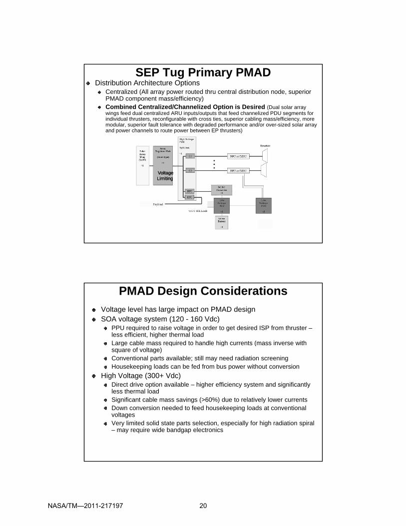
SEP Tug Primary PMADDistribution Architecture Options
Centralized (All array power routed thru central distribution node, superior PMAD component mass/efficiency)Combined Centralized/Channelized Option is Desired (Dual solar array wings feed dual centralized ARU inputs/outputs that feed channelized PDU segments for individual thrusters, reconfigurable with cross ties, superior cabling mass/efficiency, more mod lar s perior fa lt tolerance ith degraded performance and/or o er si ed solar arramodular, superior fault tolerance with degraded performance and/or over-sized solar array and power channels to route power between EP thrusters)
VoltageVoltageLimitingLimiting
PMAD Design Considerations
Voltage level has large impact on PMAD designSOA voltage system (120 - 160 Vdc)
PPU required to raise voltage in order to get desired ISP from thruster –less efficient, higher thermal loadLarge cable mass required to handle high currents (mass inverse withLarge cable mass required to handle high currents (mass inverse with square of voltage)Conventional parts available; still may need radiation screeningHousekeeping loads can be fed from bus power without conversion
High Voltage (300+ Vdc)Direct drive option available – higher efficiency system and significantly less thermal loadSignificant cable mass savings (>60%) due to relatively lower currentsg g ( ) yDown conversion needed to feed housekeeping loads at conventional voltagesVery limited solid state parts selection, especially for high radiation spiral – may require wide bandgap electronics
NASA/TM—2011-217197 20

PMAD Design Considerations (con’t)Non-direct drive:
Delivers predetermined range of I/V to EP thruster PPUsPPU power conditioning to the thrusterDecoupling, galvanic isolation between the source (array) and thruster
Simplifies ground testing of individual components (solar array, EPS, EP subsystem)May simplifies design of solar array electrical simulator
Prevents interactions from multi-thrusters through the power busImproves overall power quality for the high voltage bus
Direct drive offers:Highest kw/kg performance and superior power efficiencyIncreased reliability, lower recurring costRequires no new high voltage/power electronics tech developmentq g g p pBus voltage control is primarily tied to EP thruster operationPast direct drive system ground tests show stable operation, but more work is needed
Stability/ops during EP start-up/shut-down transitionsCathode current sharing for multi-thruster opsEffective grounding schemes
PMAD Design Considerations (con’t)Solar array regulator/limiter
Protects from short-lived, high bus voltage post-eclipse with low loadAdditional mass/efficiency hit, and adds to thermal load
Fault tolerance a significant driver for human missionsReduced-power may be challenging at significant distance from EarthReduced power may be challenging at significant distance from EarthDesign for ability to tolerate loss of thrusters and/or power feeds
Thruster out capability – How many failures tolerated?Carry cold-spare thrusters, orDe-rate thrusters nominally and power up after failure(s)
GroundingNegative solar array grounding to the tug chassis desiredPositive solar array ground is unacceptablePositive solar array ground is unacceptable
Introduces solar array plasma arcingIntroduces untenable solar array sputtering from EP plume ions
NASA/TM—2011-217197 21
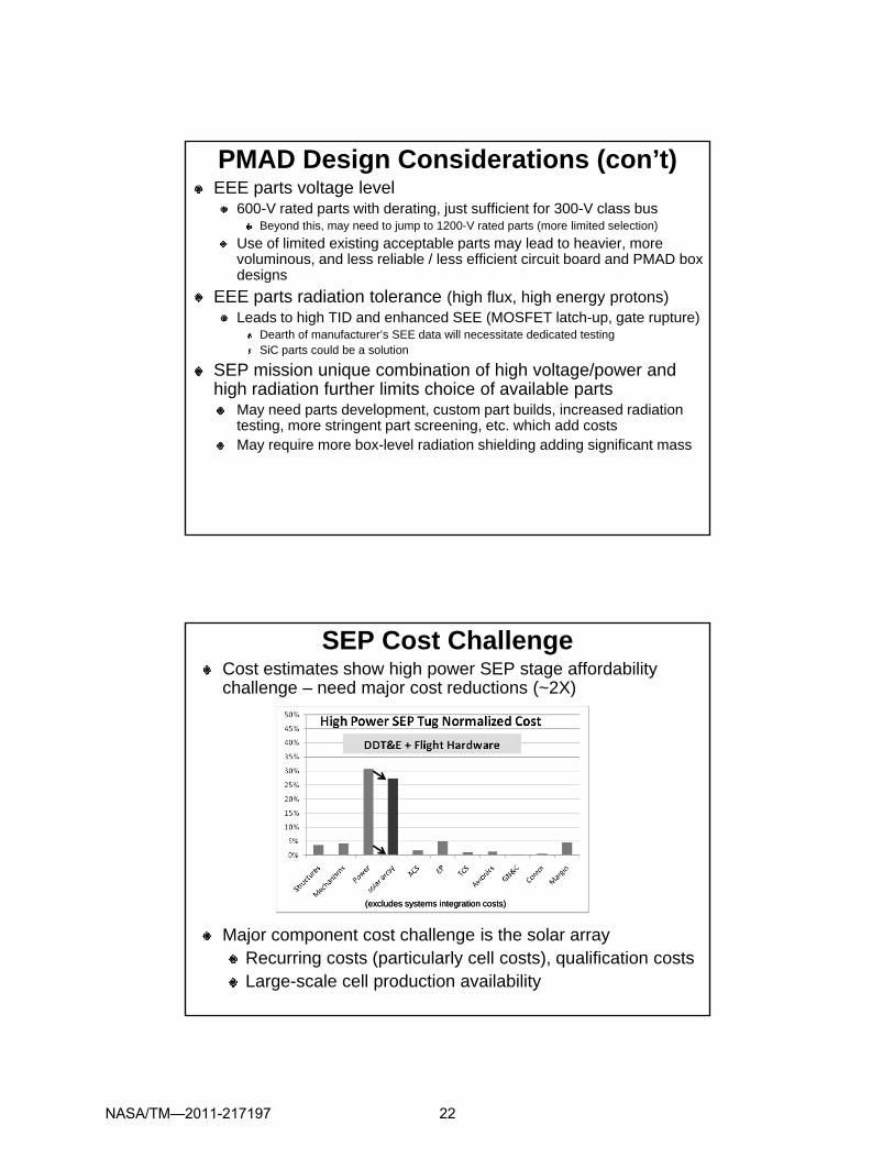
PMAD Design Considerations (con’t)EEE parts voltage level
600-V rated parts with derating, just sufficient for 300-V class busBeyond this, may need to jump to 1200-V rated parts (more limited selection)
Use of limited existing acceptable parts may lead to heavier, more voluminous, and less reliable / less efficient circuit board and PMAD box designsdesigns
EEE parts radiation tolerance (high flux, high energy protons)Leads to high TID and enhanced SEE (MOSFET latch-up, gate rupture)
Dearth of manufacturer’s SEE data will necessitate dedicated testingSiC parts could be a solution
SEP mission unique combination of high voltage/power and high radiation further limits choice of available parts
May need parts development, custom part builds, increased radiation testing, more stringent part screening, etc. which add costsMay require more box-level radiation shielding adding significant mass
SEP Cost ChallengeCost estimates show high power SEP stage affordability challenge – need major cost reductions (~2X)
Major component cost challenge is the solar arrayRecurring costs (particularly cell costs), qualification costsLarge-scale cell production availability
(excludes systems integration costs)(excludes systems integration costs)
NASA/TM—2011-217197 22

Closing Comments
High power SEP tug missions offer attractive benefits
Many {solvable} technical challenges remain and must eventually be meteventually be met
Yet programmatically, to progress beyond just SEP mission studies, major cost reductions are needed
NASA/TM—2011-217197 23

REPORT DOCUMENTATION PAGE Form Approved OMB No. 0704-0188
The public reporting burden for this collection of information is estimated to average 1 hour per response, including the time for reviewing instructions, searching existing data sources, gathering and maintaining the data needed, and completing and reviewing the collection of information. Send comments regarding this burden estimate or any other aspect of this collection of information, including suggestions for reducing this burden, to Department of Defense, Washington Headquarters Services, Directorate for Information Operations and Reports (0704-0188), 1215 Jefferson Davis Highway, Suite 1204, Arlington, VA 22202-4302. Respondents should be aware that notwithstanding any other provision of law, no person shall be subject to any penalty for failing to comply with a collection of information if it does not display a currently valid OMB control number. PLEASE DO NOT RETURN YOUR FORM TO THE ABOVE ADDRESS.
1. REPORT DATE (DD-MM-YYYY) 01-12-2011
2. REPORT TYPE Technical Memorandum
3. DATES COVERED (From - To)
4. TITLE AND SUBTITLE Solar Electric Propulsion (SEP) Tug Power System Considerations
5a. CONTRACT NUMBER
5b. GRANT NUMBER
5c. PROGRAM ELEMENT NUMBER
6. AUTHOR(S) Kerslake, Thomas, W.; Bury, Kristen, M.; Hojnicki, Jeffrey, S.; Sajdak, Adam, M.; Scheidegger, Robert, J.
5d. PROJECT NUMBER
5e. TASK NUMBER
5f. WORK UNIT NUMBER WBS 735785.01.02.01.03
7. PERFORMING ORGANIZATION NAME(S) AND ADDRESS(ES) National Aeronautics and Space Administration John H. Glenn Research Center at Lewis Field Cleveland, Ohio 44135-3191
8. PERFORMING ORGANIZATION REPORT NUMBER E-17882
9. SPONSORING/MONITORING AGENCY NAME(S) AND ADDRESS(ES) National Aeronautics and Space Administration Washington, DC 20546-0001
10. SPONSORING/MONITOR'S ACRONYM(S) NASA
11. SPONSORING/MONITORING REPORT NUMBER NASA/TM-2011-217197
12. DISTRIBUTION/AVAILABILITY STATEMENT Unclassified-Unlimited Subject Category: 20 Available electronically at http://www.sti.nasa.gov This publication is available from the NASA Center for AeroSpace Information, 443-757-5802
13. SUPPLEMENTARY NOTES Adam M. Sajdak, Michigan State University, USRP, summer intern.
14. ABSTRACT Solar electric propulsion (SEP) technology is truly at the “intersection of commercial and military space” as well as the intersection of NASA robotic and human space missions. Building on the use of SEP for geosynchronous spacecraft station keeping, there are numerous potential commercial and military mission applications for SEP stages operating in Earth orbit. At NASA, there is a resurgence of interest in robotic SEP missions for Earth orbit raising applications, 1-AU class heliocentric missions to near Earth objects (NEOs) and SEP spacecraft technology demonstrations. Beyond these nearer term robotic missions, potential future human space flight missions to NEOs with high-power SEP stages are being considered. To enhance or enable this broad class of commercial, military and NASA missions, advancements in the power level and performance of SEP technologies are needed. This presentation will focus on design considerations for the solar photovoltaic array (PVA) and electric power system (EPS) vital to the design and operation of an SEP stage. The engineering and programmatic pros and cons of various PVA and EPS technologies and architectures will be discussed in the context of operating voltage and power levels. The impacts of PVA and EPS design options on the remaining SEP stage subsystem designs, as well as spacecraft operations, will also be discussed. 15. SUBJECT TERMS Electric power; Solar arrays; Electric propulsion
16. SECURITY CLASSIFICATION OF: 17. LIMITATION OF ABSTRACT UU
18. NUMBER OF PAGES
29
19a. NAME OF RESPONSIBLE PERSON STI Help Desk (email:[email protected])
a. REPORT U
b. ABSTRACT U
c. THIS PAGE U
19b. TELEPHONE NUMBER (include area code) 443-757-5802
Standard Form 298 (Rev. 8-98)Prescribed by ANSI Std. Z39-18

