solar desalination using humidification - dehumidification technology
TRANSCRIPT
DESALINATION
ELSEVIER Desalination 142 (2002) 119-133 www.elsevier.com/locate/desal
Solar desalination using humidification- dehumidification technology
Hassan E.S. Fath4b*, Ahmad Ghazy” “Mechanical Department, Alexandria University, Alexandria, Egypt
bEl Banna Desalination and Energy Technology, 3 Yehia El-Sayed Ebraheem No. 10, Sporting, Alexandria, Egypt Tel. +20 (3) 546-9378; Fax +20 (3) 592-1853; email: [email protected]
Received 2 March 2001; accepted 28 August 2001
Abstract
A numerical study has been carried out to investigate the performance of a simple solar desalination system using humidification-dehumidification processes. The desalination system consists of a solar air heater, humidifier, dehumidifier and a circulating air-driving component. The study covers the influence of different environmental, design, and operational parameters on the desalination system productivity. Environmental parameters include solar intensity, ambient temperature and wind speed. Design parameters include the solar heater base insulation, the humidifier and the dehumidifier effectiveness. Operational parameters include air circulation flow rate, feed water rate and temperature. The results indicated that the solar air heater (energy source) efficiency significantly influences system productivity. Increasing the solar intensity and ambient temperature and decreased wind velocity increases system productivity. Increasing the air flow rate up to 0.6 kg/s increases the productivity, after which it has no significant effect. The feed water flow rate has an insignificant influence on system productivity. The surprising result is that the dehumidifier effectiveness has an insignificant influence on system productivity, which has a very important implication for the system’s economy. The physical explanation of this finding is given.
Keywords: Desalination; Solar energy; HVAC
1. Introduction phase change (freezing) -was used to separate
A diversity of desalination technologies - fresh water from saline water. These technologies
multi-stage flash (MSF), multiple-effect (MED), are expensive, however, for the production of
vapor compression (VC), reverse osmosis (RO), small amounts of fresh water. In addition, the use
electrodialysis (ED and EDR), ion exchange, and of conventional energy (hydrocarbon fuels) sources to drive these technologies has a negative
*Corresponding author. impact on the environment.
001 l-9164/02/$- See front matter 0 2002 Elsevier Science B.V. All rights reserved
PII: SO01 I-9164(01)00431-3

120 H.E.S. Fath, A. Ghazy / Desalination 142 (2002) 119-133
Solar desalination processes, on the other hand, present a promising alternative that can partially support human needs for fresh water with a renewable, free and environmentally friendly energy source. The development of solar desalination systems has demonstrated its suitability for the desalination process when weather conditions are suitable, The problem of the relative higher water production cost of solar desalination systems (over conventional energy resources systems) triggered scientists and engi- neers to investigate various means of improving system productivity, thermal efficiency, and reliability in order to reduce water production costs. For many reasons, seawater desalination can be considered to be an application of great interest for solar energy because: l a shortage of fresh water in many regions of
the world lacking conventional energy resources where there are good insolation levels and abundant seawater resources;
l there is a certain coincidence between the seasonal and daily demands offresh water and availability of solar radiation;
l solar desalination systems have not been optimized, and the technology could be improved to make the system more reliable, efficient and competitive.
Solar desalination may be divided into direct and indirect methods. In the direct methods, the solar energy collector and desalination unit is an integral unit, e.g., solar stills. In the indirect method, the solar energy is first converted to usable heat or electricity which is then used as an energy source for desalination units. Studies in direct solar distillation involving both single- and multi-effect solar stills have been carried out [l-3].
One problem that negatively influences a solar still’s performance is the direct contact of the heating element (solar absorber) and saline water. This causes deposits of scale and corrosion which deteriorate the unit’s performance. To avoid this
scenario, one should separate the two elements and use a cleaner working fluid between them. This could be carried out through the humidi- fication and dehumidification process where the heating element and the saline water are sepa- rated by a working medium such as air. This could be done either through atmospheric air humidity recovery or building a system for air humidification and dehumidification.
The concept of an atmospheric air humidity recovery process is not new. It is the method where natural humid atmosphere collects limited amounts ofwater. In some areas, in the desert, for instance, the nights are cool and the relative humidity rises up to 50% and in some places up to 100%. This gives the opportunity to collect the condensate. LeGoff [4] described that in the Sahara Desert before sunrise, people collected fresh water from the atmosphere in funnel-shaped holes in the ground lined with a plastic sheet. Based on this principle, a method to collect atmospheric humidity by condensation and by absorption was developed [4]. Another air humi- dification method suitable for coastal regions of the UAE was described by Khalil [5] where the condensate of moist air passes over cooling coils of air conditioners which is then collected as fresh water for human use. The method is economical if fresh water is considered as a by- product of AC systems.
A pilot plant system was built at Kuwait University. The operation of this plant was analyzed in a paper by Younis et al. [6]. They used a salt gradient solar pond with a 1700 m2 surface area to load the air with humidity and collect the fresh water by cooling the air in a dehumidifying column, producing 9.8 m3/d of distillate.
Another method of atmospheric air humidity recovery is the use of the adsorption-desorption technique. The principle of this method is to pass humid air over a hot adsorbing material where water can be adsorbed while cooling the adsorbing material. In a regeneration process, the

H.E.S. Fath, A. Ghazy/ Desalination 142 (2002) 119-133 121
adsorber material is heated while its water is adsorbed by an air stream that then flows on a cooler condenser to condense the water. Bulang [7] suggested the use of this principle in a solar operation unit for the recovery of water from air. It was found that many adsorbing materials could be used. However, silica gel has proved to be the most appropriate material for working between the ambient temperature and the temperature achievable by flat-plate collectors. It was also found that 100 g of silica gel can adsorb about 30 g of water from air with a relative humidity higher than 60%. Safrata [S] gave the data and results of an adsorption-desorption cycle studied at a mobile unit for the environment of Riyadh, Saudi Arabia, for different atmospheric condi- tions. With a relatively humidity of 35-46%, an amount of 1332 kg/d of water was collected.
The extraction of water vapor from the atmosphere has the disadvantages of uncontrolled humidity conditions (no one can guarantee atmospheric conditions, and wind can blow off any artificial atmosphere humidifier) - there- fore, an uncontrolled production rate. The alternative is to build a controlled system of the air humidification and dehumidification process using solar energy. For one system, saline water could be heated in a solar water heating system and then injected into the air stream for humidi- fication. This system, however, will not solve the problem of a saline water-solar collection (heating) system direct contact which results in system deterioration due to scale/corrosion/ plugging.
Alternately, the air is heated through a solar air heater (or concentrator) and the hot air is then humidified in a humidifier by saline water injection where specific humidity increases. The humid air passes through a cooler, dehumidifier, for dehumidification where the gained humidity represents the product (distilled) water. Air as a heat carrier at a temperature less than 80°C allows the use of economical materials for system components.
The technical method was developed at the University of Arizona in cooperation with the Georgia Institute of Technology, which built a humidification cycle distillation pilot plant at Puerto Pehasco, New Mexico. The plant consists of a solar collector field, a packed tower evapo- rator and a condensation column [9].
A solar rain tower desalination plant was installed in Tunisia [lo]. The plant consists of a spray tower, a cooling tower and has 8 1 m2 active surface solar flat-plate collectors. It used brackish feed water to produce 2.4-3.6 m3/d of fresh water at 60-80°C temperature. The produced water was used for drip irrigation and greenhouse heating.
A triple-effect humidification-dehumidifi- cation system was described by El-Saied et al. [ 111. The feed water is circulated through a solar collector for heating, then through a series of packed tower evaporators where water vapor is carried out by the counter flow of air. The humidified air is then recirculated in a series of heat-exchanger condensers, and it is dehumidi- tied while preheating the feed. The product distillate is collected at the bottom of each effect.
Chafik et al. [12] suggested a multi-stage system where the air goes through a series of air heating-air humidification processes (to increase the specific humidity) before it is cooled by one cooler for dehumidification. A pilot unit of 1 .O m3 production is now under construction for process verification. The expected high-pressure drop of the multi-stage (multi-components of air solar heating-humidification-demisters-connecting pipes) system is a drawback which eliminates the possibility of using the natural circulation of air (self-regulating and free-driving energy).
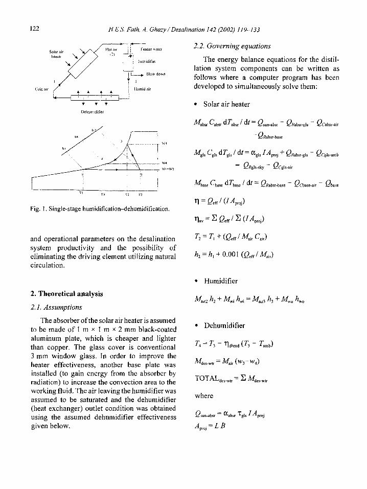
This paper presents a numerical study and analysis of a single-stage humidification- dehumidification solar desalination method process (Fig. 1). The desalination system consists of a solar air heater, humidifier (of falling film sea water), dehumidifier (an air-cooled heat exchanger) and an air-driving component (fan). The study covers different environmental, design,
122 H.E.S. Fath, A. Ghazy/Desalination 142 (2002) 119-133
Dehumtdilier
TI l’i T; T2
Fig. 1. Single-stage humidification-dehumidification.
and operational parameters on the desalination system productivity and the possibility of eliminating the driving element utilizing natural circulation.
2. Theoretical analysis
2. I. Assumptions
The absorber ofthe solar air heater is assumed to be made of 1 m x 1 m x 2 mm black-coated aluminum plate, which is cheaper and lighter than copper. The glass cover is conventional 3 mm window glass. In order to improve the heater effectiveness, another base plate was installed (to gain energy from the absorber by radiation) to increase the convection area to the working fluid. The air leaving the humidifier was assumed to be saturated and the dehumidifier (heat exchanger) outlet condition was obtained using the assumed dehumidifier effectiveness given below.
2.2. Governing equations
The energy balance equations for the distil- lation system components can be written as follows where a computer program has been developed to simultaneously solve them:
l Solar air heater
l Humidifier
MaiR h, + ML h,i = Ma+3 h, + MA h,,
l Dehumidifier
T4 = T3 - r)dhmd (& - Tamh)
M des-wtr = M,ir (“‘~-WA)
TOTAL,,,,, = 2 Mdes_*
where
Qrun-absr = %bsr ‘:g~s ‘Apmj
A,,, = L B

H.E.S. Fath, A. Ghazy /Desalination 142 (2002) 119-I 33 123
QRabsr-gls = (5 ‘absr Aproj (cbsr - ck >
&bsr-gls = &bsr ‘&IT cTabsr - Tavl)
ffabsr = 0.0336 (K/L) (L v,,, / V)”
A,,=2LB
T,", = 0.5 (T, + T,)
!&absr-base = 0 EabsrApro, (cbsr - %se )
&absr-g,r = CJ %bsr AP~~, (cbs, - Gbase >
Qcgls-amb = Hamb Aproj <rg,s - Tamb)
Hamb= 5.7 + 3.8 Vwnd
Q,zg,s-sky = 0 ~~1s APro, (74,,, - Gy > Tsky = [0.0522 (Tamb + 273)15] -273
Qcg,r-am = f&Is Apro, CT,,, - Ta,,) H,,, = 0.0336 (K’L) (L V,,, / v)08
Q(base-air = Hbase Apq cTbase - Tav~)
ffbase = 0.0336 (K/L) (L v,,, / V)‘*
Qbase = ‘base Aproj cTavl - Tamb)
Qeff - Q(:atw-air + Qcgls-air f Q(%ase-au
k, = Cm Tw, hw, = Cw, Two
Mir3 = MirZ + Mir (w3-w2)
Mr = Ma,,, / (WI + 1)
NW = Mw~ - M,ir (w3-w2)
3. Results and discussion
The overall solar air heater performance is shown in Fig. 2. The heater efficiency is in the
range of 45%, i.e., the effective heat gained is 45% of the input energy while the rest of the energy is lost. Details of the contribution of the effective energy components to the overall heat gained are shown in Fig. 3 where the heat transfer from the heater absorber to the working fluid (QCabsr_) represents the major contribution of about 60%. Nevertheless, one should notice the significant contribution of the additional base surface to effective heat (QC~__.J which repre- sents about 24%. The main heat losses from the heater (Fig. 4) are the convection from the glass to the ambient. Fig. 5 shows the temperature variations of the heater elements.
The distilled water produced from the humidi- fication-dehumidification system is in the range of 3.5 kg/m*.d for the reference case parameters (see Table 1). The effect of environmental, design, and operation parameters are shown in Figs. 6-12. For the environmental parameters, increasing solar intensity (Fig. 6), ambient temp- erature (Fig. 7), and decreasing wind velocity (Fig. 8) improve the heater effectiveness and therefore the system yield. This is an advantage of solar desalination that water production increases in summer conditions which is con- sistent with the water demand during this season.
Table 1 Reference case
_ ..__ ___
Parameters Minimum Reference Maximum
Environmental:
10 T amb
Wind YeI Design:
r)humd
qdehumd
u base
Operational:
Kl, A4 wafer T,
600 800
10 20 0 .5
.4 .6 .8
.l .2 .4 .6 .8 0 1 2
.Ol .02 0.3-1.8
.OOOl .0002 .0003 40 50 60
1000 30 1

124 H. E.S. Fath, A. Ghazy /Desalination 142 (2002) 119-133
900
800
700
600
lj 500
iii
3 _ 400
a
300
200
100
rime (h) Fig. 2. Overall heater performance (reference case).
900
800
700
600
- 500 "E
p 400
z 300
200
100
0
-100
___ . . . . . _ _., .-. . _._
4 6 ib --- .._ _.. --
Time (h)
Fig. 3. Component of effective heat gained (Q,,) (reference case).
Reducing wind velocity could be achieved through the installation of dampers around the solar collector field.
The effect of the system design parameters on the system yield are given in Figs. 9-12. The
convection loss from the heater base to the ambient is not significant, as shown in Fig. 4, and, therefore, on the system yield (Fig. 9). The economics of adding more insulation to the base shoutd be justified by gaining more distilled

H. E.S. Fath, A. Ghuzy / Desalination 142 (2002) 119-l 33 125
400
3w
Xl0
jr50
‘2 2OO
g 150
a
100
50
0
-50
Qloss
QRatjsi_sliy
-_..--_a___
2 4 6 8 IO Ii
.-- __.__... - ___. -“-__----l.~-----.l---_..---
Time fh)
Fig. 4. Component of heater heat losses (Q,,,,) (reference case).
90
80
70
20
10
0 0 2 4 6 6 IO 12 14
Time (h)
Fig. 5. Heater element temperature distribution (reference case),
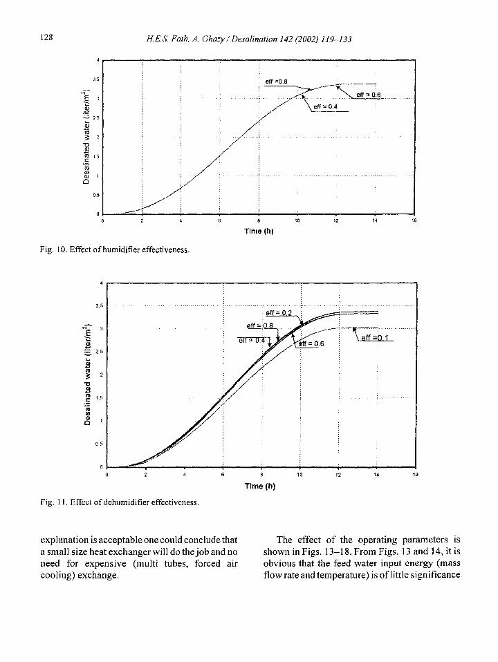
water. The other two design parameters, the since we assumed that the air will have 100% humidifier and the dehumidifier effectiveness humidity at the humidifier outlet. It is, however, have similar insignificant influence on the system surprising to see that the dehumidifier effective- yield as shown in Figs. 10-12. It is seen that ness has little influence on the system yield. Jt is there is almost no effect on humidi~er efficiency very important to discuss this finding since the

126 H. E.S. Fath, A. Ghazy / Desalination 142 (2002) 119-133
-*-c
0 2 4 6 6 10 12 14
Fig. 6. Effect of solar intensity. Time (h)
-, i Tamb.! = 20 C
0 2
Fig. 7. Effect of ambient temperature.
4 6 6 10 12 14
Time (h)
cost of the dehumidifier (the air-cooled heat air. Nevertheless, the air will still carry and exchanger) is a major part ofthe system cost. The maintain its energy (enthalpy) to the heater and explanation of this finding is that for lower the humidifier for another cycle (gain more effectiveness, the dehumidifier will not be able to heating and specific humidity) and then get cool (and dehumidify) the circulating saturated dehumidified in the dehumidifier. Any energy

H. E.S. Fath, A. Ghazy / Desalination 142 (2002) 119-133
wind vel = 0 n+
ii
Fig. 8. Effect of wind velocity.
1 6 B
Time (h)
I4 Ifi
0
Fig. 9. Effect of U,,,.
127
5 8 IO 12 14
Time (h)
which cannot be released in the dehumidifier for energy gained in the heater is the same and the one (or more) cycle(s) will be maintained to the total water evaporated in the humidifier is almost next cycle(s) till the air temperature is high the same and will be condensed and produce enough to start cooling and dehumidifying. almost the same yield. The only difference is the Fig. 12 shows the instantaneous production for small value of the energy losses of the circulating different dehumidifier effectiveness. The total air for the different effectiveness. If this
128 H.E.S. Fath, A. Ghazy / Desalination 142 (2002) 119-133
2 4 6 8
Time (h)
Fig. 10. Effect of humidifier effectiveness.
10 12 14 16
0 2 4
Fig. 11. Effect of dehumidifier effectiveness.
8
Time (h)
explanation is acceptable one could conclude that The effect of the operating parameters is a small size heat exchanger will do the job and no shown in Figs. 13-18. From Figs. 13 and 14, it is need for expensive (multi tubes, forced air obvious that the feed water input energy (mass cooling) exchange. flow rate and temperature) is of little significance

H.E.S. Fath, A. Ghazy / Desalination 142 (2002) 119-133 129
. . .._ 1 ( .
0 2 4 6 6 10 12 14
Time (h)
Fig. 12. Effect of dehumidifier effectiveness.
0 2 4 6 6
Time (h)
10 12 14 16
Fig. 13. Effect of feed water mass flow rate.
to the system yield since the total energy gained for production and 2 L for blowdown) is suffi- (carried-out with the evaporated vapor) is very cient. Similarly, there is no need to worry about small as compared to the air energy gained from preheating the feed water to a higher temperature the heater. So an input feed of 6 L/d (about 4 L than ambient. This will minimize additional

130 H.E.S. Fath, A. Ghazy / Desalination 142 (2002) 119-133
----- if i-
,.....
/
Ttii = 50 I
0 2 4 6 8 10 12 14
Time (h)
Fig. 14. Effect of feed water temperature.
0 2 4 6 8 10 12 14 16
Time (h)
Fig. 15. Effect of air mass flow rate.
capital (preheater), operation (pumping), and heater, and the second is to carry more vapor in maintenance (scale deposit cleaning) costs. The the humidifier (Figs. 15-17). Fig. 17 shows the only significant operating parameter influencing effect of increasing air flow rate on the system the yield is the circulating air flow rate. yield, which indicates that the yield will Increasing air flow rate has two effects: the first asymptote to a constant value of 5.1 L/m* after a is to improve the effective heat gained from the 0.7 kg/s air flow rate. A close look at the figure

H. E.S. Fath, A. Ghazy / Desalination 142 (2002) 119-133 131
0 0 01 0 02 003 0.04 0.05 006 0.07 006 0.09 0.1
Air mass flowrate (kg/s)
Fig. 16. Effect of increasing the circulating air mass flow rate.
6
0
0 02 0.4 06 06 1 1.2 1.4 1.6 16
Air mass flowrate (kg/s)
Fig. 17. Effect of increasing the circulating air mass flow rate.
indicates that for the low flow rate of about 0.1 kg/s, the system yield is 4.5 L while the maxi- mum yield is 5.1 L (a reduction of only 11%). The significance of thinking of a lower flow rate is for the possibility of going for natural
circulation and eliminating the circulating fan to (again) minimize the capital (fan cost), opera- tional (electric power), and maintenance (rotating equipment in humid environment) costs. Fig. 16 shows the effect of low air flow rates (where

132 H.E.S. Fath, A. Ghazy / Desalination 142 (2002) 119-133
60
5 gJ .,, ;.. -.._. .- e :
Fded water t&mperatureU~j,) ! ; . . _y.____.._” . “._.,:__.
2 ? B!owdo&n tdmperaturei (Two) i
= 40 zi
; c.~: _~~>_._-r-~r.~-~-j:-. _:R-Ry-. ~_._..._~-_‘--.&_ ;_
& ,,I : --I__ :
g 30
I\.. _.A" ; "+--___ --
g
20 t ; I .:.....
0 2 4 6 6 10 12 14
Time (h)
Fig. 18. Variation of feed and blowdown water temperature
natural convection could be used) on the system yield. With a higher heater outlet temperature (going for solar concentrator) and installing a thermal chimney after the heater (vertical pipe), natural circulation could be enhanced to justify the flow rate requirements. Fig. 18 shows the var- iation of feed and blowdown water temperatures.
4. Conclusions
1. A numerical study was carried out to investigate a solar desalination method using humidification-dehumidification processes. The desalination system consists of a solar air heater, humidifier, dehumidifier, and air-driving compo- nent. The study covers different environmental (solar intensity, ambient temperature, and wind speed), design (heater base insulation, the humidifier, and the dehumidifier effectiveness) and operational (feed water rate, temperature, and air circulation flow rate) parameters.
2. The results indicated that solar air heater efficiency significantly influences the system’s productivity. Increasing the solar intensity and ambient temperature and decreasing wind velocity increase system productivity. Increasing the air flow rate up to 0.7 kg/s increases the productivity, after which it has no significant
effect. The feed water flow rate and temperature have an insignificant influence on the system’s productivity.
3. The surprising result is that dehumidifier effectiveness also has an insignificant influence on system productivity, which has very important implications since the cost of the dehumidifier (air cooled heat exchanger) is a major part of the system’s cost.
4. A sufficient circulating air flow rate could be obtained through natural convection (to elimi- nate the driving component and its capital, operational and maintenance costs) through effective design. Using a solar concentrator and adding a thermal chimney will enhance natural circulation.
5. Symbols
A - B - c - h - h - ff -
I - k -
Area, m2 Heater width, m Specific heat, J/kg “C Specific enthalpy, J/kg Latent heat of evaporation, J/kg Film coefficient of heat transfer, W/m* “C Solar intensity, W/m2 Thermal conductivity, W/m.‘C

H.E.S. Fath, A. Ghazy / Desalination 142 (2002) 119-l 33 133
A4 - -
F - Q - T - t - u -
V -
v - W -
Mass, kg Mass rate, kg/s Pressure, Pa Heat transfer rate, W Temperature, “C Time, s Overall coefficient of heat transfer, W/m2 “C Velocity, m/s Volume, m3 Specific humidity, kg,,,,/kg,,
Greek
; z
E -
T - P - 0 - 7 - x - v -
Absorbtivity Difference Emissivity Efficiency Reflectivity Radiation constant Transmissivity Summation Kinematics viscosity
Subscripts
air - Air amb - Ambient av - Average absr - Absorber base - Base c - Convection gls - Glass hmd - Humidification 0 - Outlet proj - Projected R - Radiative
wtr - Water wnd - Wind 1 - Inlet (to heater) 2 - Inlet (to humidifier) 314 - Inlet to/outlet from dehumidifier)
References
[l] H.E.S. Fath, Desalination, 116 (1998) 45. [2] H.E.S. Fath, EncyclopediaofDesalination and Water
Resources (DESWARE), EOLSS, Section 10.2.5.3, 2000.
sky - Sky
[3] H.E.S. Fath,EncyclopediaofDesalination and Water Resources (DESWARE), EOLSS, Section 10.2.5.4, 2000.
[4] P. Le Goff and H. Le Goff, Proc. New Technologies for the Use of Renewable Energy Sources in Water Desalination, Athens, 1991, pp. 99-l 14.
[5] A. Khalil, Desalination, 34 (1993) 587. [6] M.A. Younis, M.A. Darwish and F. Juwayhel,
Desalination, 94 ( 1993) 11. [7] W.G. Bulang, Solar water recovery from air, Solar
Energy International Progress, Vol. 3, Permamon Press, New York, 1978, pp. 15261545.
[S] H. Sofiata, Proc. Second SOLERAS Workshop on Solar Water Desalination, B.H. Khoshaim and J.S. Williamson, eds., Denver, 1981, pp. 313-318.
[9] C.N. Hodges, T.L. Thompson, J.E. Groh and D.H. Frieling, Solar distillation utilizing multiple effect humidification, Final Report, University of Arizona, 1966.
[lo] Private communication with Desalination editor, 2000.
[l l] M.M. Elsayed, IS. Tahaand J.A. Sabbagh, Scientific Publishing Center, King Abdulaziz University, KSA, 1986.
[12] E. Chatik, A new seawater desalination process using solar energy, Proc. 6th AQUA-TECH Conference, Cairo, 2001.