solar desalination system using spray evaporation
TRANSCRIPT

lable at ScienceDirect
Energy xxx (2014) 1e8
Contents lists avai
Energy
journal homepage: www.elsevier .com/locate/energy
Solar desalination system using spray evaporation
S.A. El-Agouz a, *, G.B. Abd El-Aziz b, A.M. Awad b
a Mech. Eng. Dep., Faculty of Eng., Tanta Univ., Egyptb Mech. Dept., Faculty of Industrial Education, Suez University, Egypt
a r t i c l e i n f o
Article history:Received 31 January 2014Received in revised form1 August 2014Accepted 3 August 2014Available online xxx
Keywords:Solar desalination systemSpray evaporationSalty waterExperimentally
* Corresponding author.E-mail addresses: [email protected],
[email protected] (S.A. El-Agouz).
http://dx.doi.org/10.1016/j.energy.2014.08.0090360-5442/© 2014 Elsevier Ltd. All rights reserved.
Please cite this article in press as: El-Agou10.1016/j.energy.2014.08.009
a b s t r a c t
This paper evaluates a one-stage technique to improve fresh water production from salty water byenhancing the evaporation and condensation. A pilot plant is designed and constructed in an arid areawith 1 m2 solar water collector area to evaluate the one-stage process. The effect of main parameters onfresh water production of the unit is studied. The results show that, the productivity, efficiency, pro-ductivity rate, and Gained Output Ratio of the desalination unit are strongly affected by the inlet hotwater temperature and flow rate. Within the studied ranges, the maximum daily productivity reached to9 l/m2. According to these results, fresher water production of the present system is higher than thatsolar humidificationedehumidification desalination system in the previous studies. The maximum dailyefficiency in the desalination system is about 87%. A TDS (total dissolved solids) of fresher water is40 ppm. Finally, the cost of distilled water per liter is $0.029.
© 2014 Elsevier Ltd. All rights reserved.
1. Introduction
Desalination based on renewable energy such as solar energy,presents a sustainable and a zero-polluting alternative to fossil fuelbased desalination, which aggravates environmental pollutionproblems. It is cheap, allows energy diversification, available forpredictable periods of time, and helps avoid dependence onexternal energy supplies (Garcia-Rodriguez [1]). Solar still desali-nation uses a sustainable and pollution-free source to producehigh-quality water.
Fresh water could be obtained from salty water through thesolar HDH (humidificationedehumidification) cycle. In this pro-cess, hot air supplied from a solar collector was circulated either bya natural or a forced convection process over the water where itbecomes humid. The humid air was then passed through acondenser or de-humidifier system where the desalinated waterwas obtained. Multi-effect humidification plants were the mosteffective units among solar desalination plants (Farid et al. [2]).Many researchers have conducted studies on process and theequipment's related to the (HDH) systems for water desalination.Abdelkader [3] studied the solar desalination system with multi-effect humidificationedehumidification cycles with couples cen-tral solar receiver. In this system, saline water was warmed through
z SA, et al., Solar desalinatio
the solar central receiver and it was then entered into a desalina-tion chamber. The air circulation in the humidification chamberwas provided by natural convection.
The amount of distillate water produced by the unit depends onthe solar collector size. The performance of the collector dependsmainly on the weather conditions, design and operating parame-ters. However, to estimate the optimum values of these parametersin different weather conditions using full experiment was costlyand time-consuming. Therefore, the development of a simulationmodel offers a better alternative and has proven to be a powerfultool in the evaluation of the performance of the system. Both airand water, solar collectors were the main components of a solardesalination unit and any improvement in their efficiency will havea direct bearing on the water production rate and the product cost(Al-Hallaj and Selman [4]). The solar collectors that were used toheat water and/or air were expensive and can reach in some casesfrom 25 to 30% of the total desalination unit cost by Ben Bacha et al.[5]. The best known thermal processes for the desalination ofseawater, namely MED (multi-effect desalination) and MSF(multistage flash), make an efficient use of energy because the heatreleased in each stage or effect was used in the next one, makingmultiple use of energy. However, these processes require a veryprecise control of temperature and pressure in each stage, whichmust be constant in time in order to keep the conditions needed forthe boiling process (El-Dessouky and Ettouney [6]). This poses aproblem when coupling desalination with solar energy, due to theintrinsic variability of insolation, thus requiring a thermal storage
n system using spray evaporation, Energy (2014), http://dx.doi.org/

Nomenclature
A Area, m2
h Enthalpy, (kJ/kg)H Solar radiation, (W/m2)L Latent heat of water, (J/kg)m Flow rate, (l/h)M Productivity, (l/h)Pp Pump power, (W)T Temperature, �C
Greek lettersh Efficiency
SubscriptsAv Averageci Cold inletco Cold outletd Dailyh Hourlyhi Hot Inlet
ho Hot outletS Solar water collectorw Water
AbbreviationsCC Cooling coilCV Control valueEC Condensation towerET Evaporation towerFM Flow meterFWR Fresh water reservoirGOR Gain output ratioHDH HumidificationedehumidificationHEX Heat exchangerMED Multiple effect distillationMSF Multi stage flashPR Productivity rateSWC Solar water collectorTC ThermocouplesTDS Total dissolved solidsTES Thermal Energy Storage
S.A. El-Agouz et al. / Energy xxx (2014) 1e82
tank and/or a supplementary heat source from fossil fuels (Blancoand Alarcon [7]).
In order to enhance utilization efficiency of the latent heat ofcondensation, gain more fresh water output per square meter areaof solar collector and reduce the energy loss of the humid-ificationedehumidification desalination unit, a series of designs ofmulti-effect solar humidificationedehumidification desalinationsystem were presented by some researchers.
Zhani and Ben Bacha [8] presented an experimental investiga-tion and an economic analysis on a solar desalination prototypefunctioning by HD (Humidification/Dehumidification) of air. Theexperimental results also that the outlet and the inlet temperaturesat different component levels were the same trends as solar radi-ation and the ambient air temperature was an insignificant effecton thermal performance of the unit. The cost of distilled water perliter was $0.107.
Al-Hallaj et al. [9] studied the solar driven (HDH) desalinationsystem and the daily fresh water production rate ranged fromapproximately 2.25 to 5.0 l/m2 of solar collector area, depending onthe average daily solar flux. Muller-Holst et al. [10] fabricated thesolar (HDH) desalination system for operation in Munich, Germany.The system performance showed the average daily fresh waterproduction in June was approximately 7.5 l/m2 while that inJanuary was approximately 1.2 l/m2 solar collector area. Dai andZhang [11] presented the solar desalination unit with humidifica-tion and dehumidification. They found that the performance of thesystemwas strongly dependent on the mass flow rate of salt water,the mass flow rate of the process air, and the inlet salt watertemperature to the humidifier. The results showed that the pro-ductivity achieved was around 6.2 l/m2 of solar collector area. Yuanet al. [12] investigated a 1200 l/day (HDH) desalination unit. Thissystem was composed of a 100 m2 solar air heater field, a 12 m2
solar water collector. The results showed that water production ofthe system can reach 10.7 l/m2 of solar collector area, when theaverage solar radiation was 550 W/m2. Zhani et al. [13] developedthemodeling and the experimental solar desalination unit using airand water solar collectors. They were found that the two-temperature mathematical model describes more precisely thereal behavior of the water solar collector than the one-temperaturemathematical model. Gude et al. [14] designed the low temperature
Please cite this article in press as: El-Agouz SA, et al., Solar desalinatio10.1016/j.energy.2014.08.009
desalination system using solar collectors augmented by thermalenergy storage. A solar collector area was 15 m2 with 1 m3 of TES(Thermal Energy Storage) volume or 18 m2 with 3 m3 of TES vol-ume. The results show that the fresh water production can reach6.67 l/m2 of solar collector area. Zamen et al. [15] experimentallyevaluated the two-stage technique to improve the humid-ificationedehumidification process in fresh water production fromsalty water. A two-stage pilot plant was designed and constructedin an arid area with 80 m2 solar collectors. The results show that,fresh water production can reach 7.25 l/m2 of solar collector area.
The main limitation of solar stills was their low productivitycompared to conventional desalination processes. The operatingefficiency was low due to main two limitations: (i) the rejection tothe atmosphere of the latent heat of condensation and (ii) thedifficulty of raising the evaporation temperature and decreasecondensation temperature as heating, evaporation and condensa-tion take place in one container (He and Yan [16]).
It has been inferred from the literatures that most of the pre-vious works have used heated water spray during the humidifica-tion process where air used as a carrier gas to evaporate water fromthe saline feed and to form fresh water by subsequent condensa-tion. On the fact that the vapor carrying capability of air increaseswith temperature:1 kg of dry air can carry 0.5 kg of vapor and about2805 kJ when its temperature increases from 30 to 80 �C (Parekhet al. [17]). Therefore, the solar desalination requires efficientmethods of evaporation and condensation at relatively low tem-peratures up to 70 �C. Initially for small quantity, as in the earlierdesigns the condenser is an integral part of the system. In addition,Multi-effect solar still was suggested as an efficient method for theproduction of desalinated water.
The present system is based on the generation of vapor fromsalty water when it enters an evaporator tower and condensation ofvapor is accomplished by regenerative heating of the feed water.The main objectives of the present work are to describe the designfor solar distillation system coupled with a solar water heater toenhance productivity and efficiency. The paper presents the resultsof a solar distillation system, with the water working in a closedloop. The distillation chamber consists of evaporation andcondensation towers. The system is designed to improve theevaporation rate by spraying water at low temperature.
n system using spray evaporation, Energy (2014), http://dx.doi.org/
S.A. El-Agouz et al. / Energy xxx (2014) 1e8 3
2. Process description and instrumentation
2.1. Process description
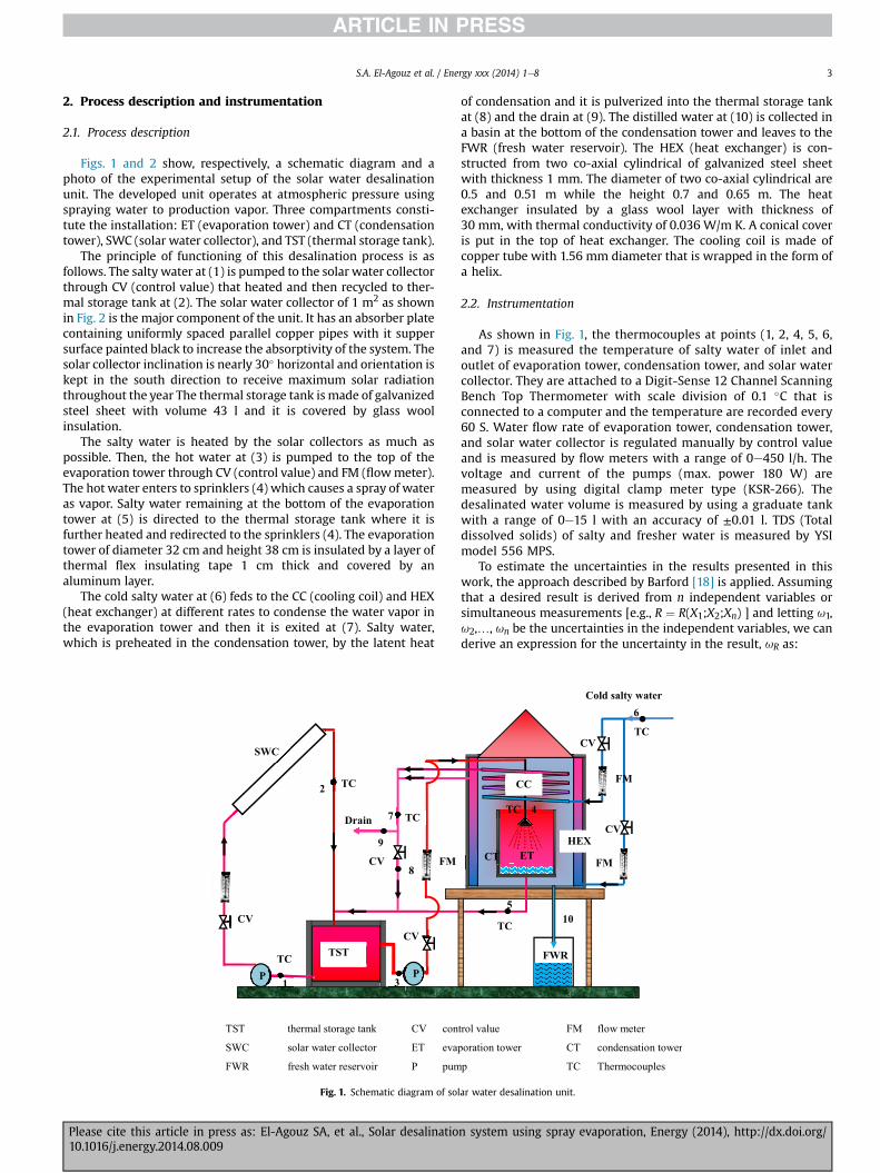
Figs. 1 and 2 show, respectively, a schematic diagram and aphoto of the experimental setup of the solar water desalinationunit. The developed unit operates at atmospheric pressure usingspraying water to production vapor. Three compartments consti-tute the installation: ET (evaporation tower) and CT (condensationtower), SWC (solar water collector), and TST (thermal storage tank).
The principle of functioning of this desalination process is asfollows. The salty water at (1) is pumped to the solar water collectorthrough CV (control value) that heated and then recycled to ther-mal storage tank at (2). The solar water collector of 1 m2 as shownin Fig. 2 is the major component of the unit. It has an absorber platecontaining uniformly spaced parallel copper pipes with it suppersurface painted black to increase the absorptivity of the system. Thesolar collector inclination is nearly 30� horizontal and orientation iskept in the south direction to receive maximum solar radiationthroughout the year The thermal storage tank is made of galvanizedsteel sheet with volume 43 l and it is covered by glass woolinsulation.
The salty water is heated by the solar collectors as much aspossible. Then, the hot water at (3) is pumped to the top of theevaporation tower through CV (control value) and FM (flowmeter).The hot water enters to sprinklers (4) which causes a spray of wateras vapor. Salty water remaining at the bottom of the evaporationtower at (5) is directed to the thermal storage tank where it isfurther heated and redirected to the sprinklers (4). The evaporationtower of diameter 32 cm and height 38 cm is insulated by a layer ofthermal flex insulating tape 1 cm thick and covered by analuminum layer.
The cold salty water at (6) feds to the CC (cooling coil) and HEX(heat exchanger) at different rates to condense the water vapor inthe evaporation tower and then it is exited at (7). Salty water,which is preheated in the condensation tower, by the latent heat
TST thermal storage tank CV con
SWC solar water collector ET eva
FWR fresh water reservoir P pum
SWC
TST
CV
CV FM
Drain
CV
2
1PP 3
7
8
9
TC
TC
TC
Fig. 1. Schematic diagram of sol
Please cite this article in press as: El-Agouz SA, et al., Solar desalinatio10.1016/j.energy.2014.08.009
of condensation and it is pulverized into the thermal storage tankat (8) and the drain at (9). The distilled water at (10) is collected ina basin at the bottom of the condensation tower and leaves to theFWR (fresh water reservoir). The HEX (heat exchanger) is con-structed from two co-axial cylindrical of galvanized steel sheetwith thickness 1 mm. The diameter of two co-axial cylindrical are0.5 and 0.51 m while the height 0.7 and 0.65 m. The heatexchanger insulated by a glass wool layer with thickness of30 mm, with thermal conductivity of 0.036 W/m K. A conical coveris put in the top of heat exchanger. The cooling coil is made ofcopper tube with 1.56 mm diameter that is wrapped in the form ofa helix.
2.2. Instrumentation
As shown in Fig. 1, the thermocouples at points (1, 2, 4, 5, 6,and 7) is measured the temperature of salty water of inlet andoutlet of evaporation tower, condensation tower, and solar watercollector. They are attached to a Digit-Sense 12 Channel ScanningBench Top Thermometer with scale division of 0.1 �C that isconnected to a computer and the temperature are recorded every60 S. Water flow rate of evaporation tower, condensation tower,and solar water collector is regulated manually by control valueand is measured by flow meters with a range of 0e450 l/h. Thevoltage and current of the pumps (max. power 180 W) aremeasured by using digital clamp meter type (KSR-266). Thedesalinated water volume is measured by using a graduate tankwith a range of 0e15 l with an accuracy of ±0.01 l. TDS (Totaldissolved solids) of salty and fresher water is measured by YSImodel 556 MPS.
To estimate the uncertainties in the results presented in thiswork, the approach described by Barford [18] is applied. Assumingthat a desired result is derived from n independent variables orsimultaneous measurements [e.g., R ¼ R(X1;X2;Xn) ] and letting u1,u2,…, un be the uncertainties in the independent variables, we canderive an expression for the uncertainty in the result, uR as:
trol value FM flow meter
poration tower CT condensation tower
p TC Thermocouples
CV
CV
FM
FM
Cold salty water
FWR
CT ET
4
510
6
4444TC
TC
TC
CC
HEX
ar water desalination unit.
n system using spray evaporation, Energy (2014), http://dx.doi.org/
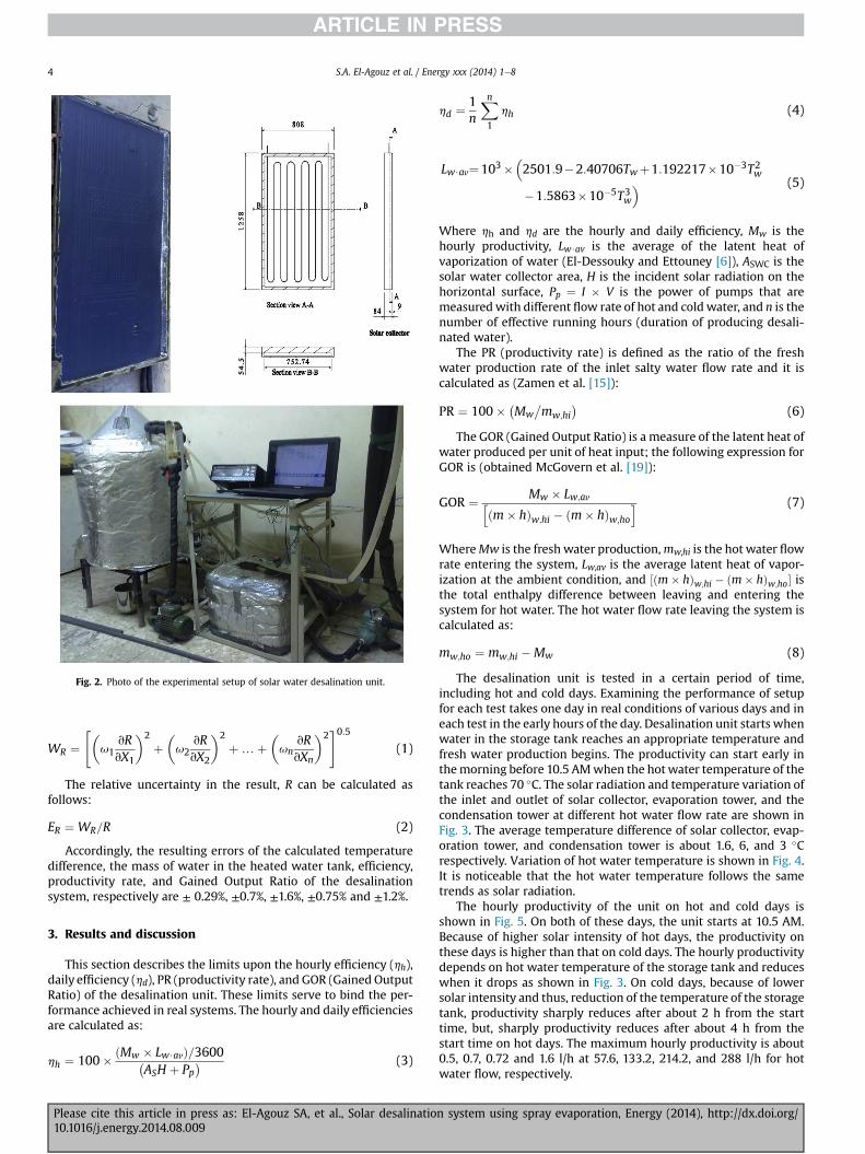
Fig. 2. Photo of the experimental setup of solar water desalination unit.
S.A. El-Agouz et al. / Energy xxx (2014) 1e84
WR ¼"�
u1vRvX1
�2
þ�u2
vRvX2
�2
þ…þ�un
vRvXn
�2#0:5
(1)
The relative uncertainty in the result, R can be calculated asfollows:
ER ¼ WR=R (2)
Accordingly, the resulting errors of the calculated temperaturedifference, the mass of water in the heated water tank, efficiency,productivity rate, and Gained Output Ratio of the desalinationsystem, respectively are ± 0.29%, ±0.7%, ±1.6%, ±0.75% and ±1.2%.
3. Results and discussion
This section describes the limits upon the hourly efficiency (hh),daily efficiency (hd), PR (productivity rate), and GOR (Gained OutputRatio) of the desalination unit. These limits serve to bind the per-formance achieved in real systems. The hourly and daily efficienciesare calculated as:
hh ¼ 100� ðMw � Lw$avÞ=3600�ASH þ Pp
� (3)
Please cite this article in press as: El-Agouz SA, et al., Solar desalinatio10.1016/j.energy.2014.08.009
hd ¼ 1 Xnhh (4)
n1
Lw$av¼103��2501:9�2:40706Twþ1:192217�10�3T2w
�1:5863�10�5T3w� (5)
Where hh and hd are the hourly and daily efficiency, Mw is thehourly productivity, Lw$av is the average of the latent heat ofvaporization of water (El-Dessouky and Ettouney [6]), ASWC is thesolar water collector area, H is the incident solar radiation on thehorizontal surface, Pp ¼ I � V is the power of pumps that aremeasuredwith different flow rate of hot and cold water, and n is thenumber of effective running hours (duration of producing desali-nated water).
The PR (productivity rate) is defined as the ratio of the freshwater production rate of the inlet salty water flow rate and it iscalculated as (Zamen et al. [15]):
PR ¼ 100� �Mw
�mw;hi
�(6)
The GOR (Gained Output Ratio) is a measure of the latent heat ofwater produced per unit of heat input; the following expression forGOR is (obtained McGovern et al. [19]):
GOR ¼ Mw � Lw;avhðm� hÞw;hi � ðm� hÞw;ho
i (7)
WhereMw is the fresh water production,mw,hi is the hot water flowrate entering the system, Lw,av is the average latent heat of vapor-ization at the ambient condition, and ½ðm� hÞw;hi � ðm� hÞw;ho� isthe total enthalpy difference between leaving and entering thesystem for hot water. The hot water flow rate leaving the system iscalculated as:
mw;ho ¼ mw;hi �Mw (8)
The desalination unit is tested in a certain period of time,including hot and cold days. Examining the performance of setupfor each test takes one day in real conditions of various days and ineach test in the early hours of the day. Desalination unit starts whenwater in the storage tank reaches an appropriate temperature andfresh water production begins. The productivity can start early inthemorning before 10.5 AMwhen the hotwater temperature of thetank reaches 70 �C. The solar radiation and temperature variation ofthe inlet and outlet of solar collector, evaporation tower, and thecondensation tower at different hot water flow rate are shown inFig. 3. The average temperature difference of solar collector, evap-oration tower, and condensation tower is about 1.6, 6, and 3 �Crespectively. Variation of hot water temperature is shown in Fig. 4.It is noticeable that the hot water temperature follows the sametrends as solar radiation.
The hourly productivity of the unit on hot and cold days isshown in Fig. 5. On both of these days, the unit starts at 10.5 AM.Because of higher solar intensity of hot days, the productivity onthese days is higher than that on cold days. The hourly productivitydepends on hot water temperature of the storage tank and reduceswhen it drops as shown in Fig. 3. On cold days, because of lowersolar intensity and thus, reduction of the temperature of the storagetank, productivity sharply reduces after about 2 h from the starttime, but, sharply productivity reduces after about 4 h from thestart time on hot days. The maximum hourly productivity is about0.5, 0.7, 0.72 and 1.6 l/h at 57.6, 133.2, 214.2, and 288 l/h for hotwater flow, respectively.
n system using spray evaporation, Energy (2014), http://dx.doi.org/

Fig. 3. Solar radiation and temperature variation in different hot water flow rate.
Fig. 4. Hot water temperature at different hot water flow rate.
S.A. El-Agouz et al. / Energy xxx (2014) 1e8 5
Please cite this article in press as: El-Agouz SA, et al., Solar desalination system using spray evaporation, Energy (2014), http://dx.doi.org/10.1016/j.energy.2014.08.009

Hot dayHot day
Hot day
Hot day
Cold dayCold day
Fig. 5. Hourly productivity at different hot water flow rate.
Fig. 6. Accumulated productivity at different hot water flow rate.
Please cite this article in press as: El-Agouz SA, et al., Solar desalination system using spray evaporation, Energy (2014), http://dx.doi.org/10.1016/j.energy.2014.08.009

Fig. 7. Effect of average hot water temperature on daily productivity, daily efficiencyand GOR at different inlet hot water flow rate.
Table 1Comparisons of the productivity rate for present system and Zamen et al. [15].
Hot water flow rate, l/h Productivity rate, %, at Thi,av ¼ 70 �C
Present system Zamen et al. [15]
57.6 1.33 0.094133.2 1.25 0.089214.2 0.69 0.084288.0 0.64 0.080
S.A. El-Agouz et al. / Energy xxx (2014) 1e8 7
Fig. 6 shows daily productivity at different hot water flow rate. Itcan be seen that daily productivity increases with the increase ofhot water temperature as shown in Fig. 4. That is because ofincreasing the temperature difference between evaporation andcondensation in which the evaporation rate is increased byincreasing the temperature difference. The maximum daily
Fig. 8. Effect of inlet hot water flow rate on productivity rate.
Please cite this article in press as: El-Agouz SA, et al., Solar desalinatio10.1016/j.energy.2014.08.009
productivity is about 5.8 l, 7.22, 7.27 and 9 l/m2 at 57.6, 133.2, 214.2,and 288 l/h for hot water flow, respectively.
Fig. 7 shows the effect of the average hot water temperature ondaily productivity, daily efficiency and GOR at different inlet hotwater flow rate. It can be noticed that by increasing the salty watertemperature, the productivity and efficiency increases. It can beseen that the heating temperature and the feed seawater mass flowrate have a significant influence on the unit productivity. Thisfinding can be explained as follows: the increase of heating tem-perature increases the vapor due to decrease the latent heat ofvaporization. Consequently, the amount of fresh water obtainedfrom the system is increased. At the same average hot water tem-perature, it can be seen that an increase in hot water flow rate in-creases daily productivity and efficiency. Daily productivity changesfrom 2.8 to 9 l/m2 depending on hot water flow rate andtemperatures.
At the hot water flow rate 57.6 l/h, the maximum daily pro-ductivity can reach 5.8 l/m2 at Thi)av¼ 68.6 �C, at the hot water flowrate 133.2 l/h, the maximum daily productivity can reach 7.22 l/m2
at Thi)av ¼ 61 �C. At the hot water flow rate 214.2 l/h, the maximumdaily productivity can reach 7.27 l/m2 at Thi)av ¼ 59.7 �C and at thehot water flow rate 288 l/h, the maximum daily productivity canreach 9 l/m2 at Thi)av ¼ 58 �C. The maximum efficiencies for presentare 68, 85, 80, and 87% at 57.6,133.2, 214.2, and 288 l/h for hotwaterflow, respectively. It can be seen that increasing the hot water flowrate five times yields twice the productivity at Thi)av ¼ 58 �C.
The GOR increases with increasing hot water temperature andflow rate. A larger value of GOR in a desalination system meanshigher energy efficiency and better distillate productionperformance.
Fig. 8 shows the effect of the inlet hot water flow rate on pro-duction rate. It can be seen that an increase in inlet hot water flowrate decreases the productivity rate while an increase in averagehot water temperature increases productivity rate. The hot waterflow rate change from 60 to 70 �C, the productivity rate increase byabout 70%.
TDS (Total dissolve solids) of salty feed water in village is morethan 3500 ppm and TDS of fresh water during the test period is lessthan 40 ppm. This shows the ability of this process in desalinationof salty water to produce potable water in arid areas.
Comparison of productivity rate for present system and Zamenet al. [15] is tabulated in Table 1 as a function of inlet hot water flowrate,mw,hi, at Thi)av ¼ 70 �C. It can be seen that an increase in waterflow rate decreases productivity rate. The results showed that theproductivity rate of the present system is higher than that for theZamen et al. [15] which uses a two-stage process at the samecondition.
Table 2The average of Thi,av, Mw,av, hd,av, and CPL at different mw,hi.
mw,hi, l/h Thi,av, �C Mw,av, l/m2 hd,av, % CPL, $/l
57.6 62.0 4.04 49.2 0.049133.2 57.8 4.92 60.0 0.040214.2 57.0 6.00 61.1 0.033288.0 53.4 6.70 63.0 0.029
n system using spray evaporation, Energy (2014), http://dx.doi.org/
S.A. El-Agouz et al. / Energy xxx (2014) 1e88
4. Economic analysis
The calculation methodology is based on; the salvage value ofthe units will be zero at the end of the amortization period. Theoperator and maintenance costs are 20% of plant annual payment(El-Dessouky and Ettouney [6]). The product water coat is calcu-lated assuming 250 working days. Economic analysis of the waterdesalination unit is given by Kabeel et al. [20]. The total cost of thefabricated system is calculated from the sum of the cost of oper-ating, the cost of maintenance, and the fixed charges cost. The costof operating; it includes the energy, the operating personnel, andthe handling of raw materials. The cost of maintenance; it includesthe maintenance personnel, the maintenance facility cost, the testequipment, the maintenance support and handling cost, themaintenance spares and repair parts. The fixed charges cost iscalculated from the present capital cost of desalination system; thecapital recovery factor, the interest per year, which is assumed as6%; and the life years are assumed as 15 years in this analysis.Finally, the cost of distilled water per liter can be calculated bydividing the annual cost of the system by annual yield of solar still.
The total cost of the fabricated system is approximately $400.Therefore, the fixed charges cost is $41.2 and operators and themaintenance costs are $8.2, then the total cost of ownership is$49.4. The average daily production of water is 6.7 l/m2. Finally, thecost of distilled water per liter is $0.029. The results showed thatthe cost of distilled water per liter of the present system is lowerthan that for the Zhani and Ben Bacha [8].
Based on the results of four days, Table 2 shows the value of theaverage of Thi)av, Mw)av, hd)av, and CPL at different mw,hi. FromTable 2, as increase inlet hot water flow rate from 57.6 to 288 l/h thecost of water production decreases from 0.049 to 0.029 $/l. Themaximum of productivity and efficiency are 6.7 l/m2 and 63%.
5. Conclusions
Significant effects of the water temperature and flow rate ofproductivity and efficiency of solar desalination system areobserved during the present experiments and the following pointsare concluded:
� The inlet hot water temperature and flow rate have an impor-tant effect on productivity, efficiency, productivity rate, andGained Output Ratio of the desalination unit.
� The increase in water flow rate increases productivity at thesame inlet average hot water temperature.
� Themaximumdaily productivity of the system reached to 9 l/m2
of solar collector area.� The maximum productivity in the new desalination system ishigher than (HDH) desalination system.
� The maximum day efficiency in the new desalination system isabout 87%.
Please cite this article in press as: El-Agouz SA, et al., Solar desalinatio10.1016/j.energy.2014.08.009
� TDS (Total dissolved solids) of salty water after desalination is40 ppm.
� The cost of distilled water per liter is $0.029.
References
[1] Garcia-Rodriguez L. Seawater desalination driven by renewable energies: areview. Desalination 2002;143:103e13.
[2] Farid MM, Parekh S, Selman JR, Al-Hallaj S. Solar desalination with a humid-ificationedehumidification cycle: mathematical modeling of the unit. Desali-nation 2003;151:153e64.
[3] Abdelkader M. Investigation of multi-effect humidification (MEH)edehu-midification solar desalination system coupled with solar central receiver. In:The 2nd International Conference on Water Resources and Arid Environment,Saudi Arabia; 2006.
[4] Al-Hallaj S, Selman JR. A comprehensive study of solar desalination withhumidification-dehumidification cycle. Project No. 98-BS-032b. MEDRC seriesof R&D reports; 2002. See also:, www.medrc.org.
[5] Ben Bacha H, Damak T, Bouzguenda M, Abid MS, YMaalej A, Ben Dhia H.A methodology to design and predict operation of a solar collector for solarpowered desalination unit using the SMCEC principle. Desalination 2003;156:305e513.
[6] El-Dessouky HT, Ettouney HM. Fundamentals of salt water desalination.Elsevier Science BV; 2002.
[7] Blanco J, Alarcon D. The PSA experience on solar desalination: technologydevelopment and research activities. In: Lucio Rizzuti, Ettouney Hisham M,Cipollina Andrea, editors. Solar desalination for the 21st century. Springer;2007.
[8] Zhani K, BenBacha H. Experimental investigation of a new solar desalinationprototype using the humidification dehumidification principle. Renew Energy2010;35:2610e7.
[9] Al-Hallaj S, Farid MM, Tamimi AR. Solar desalination with humidificationedehumidification cycle: performance of the unit. Desalination 1998;120:273e80.
[10] Müller-Holst H, Engelhardt M, Scholkopf W. Small-scale thermal seawaterdesalination simulation and optimization of system design. Desalination1999;122:255e62.
[11] Dai YJ, Zhang HF. Experimental investigation of a solar desalination unit withhumidification and dehumidification. Desalination 2000;130:169e75.
[12] Yuan G, Wang Z, Li H, Li X. Experimental study of a solar desalination systembased on humidificationedehumidification process. Desalination 2011;277:92e8.
[13] Zhani K, Ben Bacha H, Damak T. Modeling and experimental validation of ahumidification-dehumidification desalination unit solar part. Energy 2011;36:3159e69.
[14] Gude VG, Nirmalakhandan N, Deng S, Maganti A. Low temperature desali-nation using solar collectors augmented by thermal energy storage. ApplEnergy 2012;91:466e74.
[15] Zamen M, Soufari SM, Vahdat SA, Amidpour M, Zeinali MA, Izanloo H, et al.Experimental investigation of a two-stage solar humid-ificationedehumidification desalination process. Desalination 2014;332:1e6.
[16] He T, Yan L. Application of alternative energy integration technology inseawater desalination. Desalination 2009;249:104e8.
[17] Parekh S, Farid MM, Selman JR, Al-Hallaj S. Solar desalination with a hu-midification dehumidification technique a comprehensive technical review.Desalination 2004;160:167e86.
[18] Barford NC. Experimental measurements: precision., error and truth. 2nd ed.New York: John Wiley & Sons; 1990.
[19] McGovern RK, Thiel GP, G. Narayan GP, Zubair SM, Lienhard JH. Performancelimits of zero and single extraction humidification-dehumidification desali-nation systems. Appl Energy 2013;102:1081e90.
[20] Kabeel AE, Hamed AM, El-Agouz AS. Cost analysis of different solar stillconfigurations. Energy 2010;35:2901e8.
n system using spray evaporation, Energy (2014), http://dx.doi.org/