solar collector – basic installation guidelines · solar collector – basic installation...
TRANSCRIPT
Solar Collector – Basic Installation Guidelines
You are Important
As an installer you are the face of Apricus, and responsible for the final installation of the product. Apricus strives to provide the best quality product and service possible and in line with that goal it is important that you clearly understand the product and how it should be installed. This manual is designed as a basic document that you can carry around as a reference. It is important that if you are unsure about any aspect of the system operation or installation you obtain support and training from Apricus.
Who is Apricus
Apricus is a global company, with offices in the US, France and Sydney. We complete product development and manufacturing in our own production plant. The advantage of this is that we are flexible in meeting the needs of the market, be that changes to the Australia Standards, or requirements to make installation easier.
Improving the Product
We are always keen to receive feedback from you about how we can improve the product. Not all suggestions are possible to implement, but many aspects of the current product design are a result of feedback and ideas from installers like you.
Please read through this document and again, if you have any questions please contact your assigned Apricus relationship manager or Apricus Australia directly on:
1300 277 428
© 2008 - Apricus Australia Pty Ltd AA-S18.1-DL-1.1 Page 1 of 13

1. Safety
• Always wear safety glasses when handling evacuated tubes.
• Always wear leather gloves when handling steel components.
• Take extreme care when working at heights (appropriate PPE)
• It is the responsibility of the installer to adhere to all relevant health and safety precautions as specified by your relevant government authority such as Work cover.
2. Important
• If installing in a region prone to frost conditions, this solar collector must be installed in a system configuration that incorporates freeze protection, either in the form of a glycol/water closed loop, or low temperature pump operation (as included with the Apricus SolaStat-Plus controller)
• In areas prone to large hailstones (>25mm / 1”), the collector should be installed at an angle of at least 40o.
• Installation must only be completed by authorised installers, and must adhere to relevant local regulations. Do not attempt to install an Apricus solar water heating system if you have not received training from Apricus staff.
• Refer to Apricus Solar Collector Installation & Operation Manual - Aus&NZ for detailed installation instructions.
• If the hot water system does not have a tempering valve installed, always install one to avoid scolding. On an electric boosted tank the tempering valve should be installed on the hot water supply line. On a post gas boosted system, the tempering valve should be installed after the continuous flow booster.
• It is a requirement that the water be heated to 60oC at least once a day to kill Legionella bacteria. Electric and gas boosting must NOT be turned off even during the summer. For electric boosted systems, a 15 amp automatic timer is recommended with boosting set from 3-6pm each afternoon. Apricus recommends the CLIPSAL timer shown in figure 2.
• Apricus works hard to ensure all products meet Australian Standards. Changes are sometimes made to standards that require Apricus to make modifications to the product. This document outlines some such product changes. We apologise for any inconvenience this may cause.
3. Installation Preparation
• Check completeness of components prior to going to site of installation.
• Check the condition of the tubes prior to departing for the job site by opening the box and making sure the bottoms are all silver. Always take a few spare tubes.
• Assess the site for the correct collector orientation:
• Collector should face due north. 15o towards east or west is ok. If facing due west refer to the detailed installation manual for more guidelines.
• Collector must be installed at no less than a 20o angle, and preferably 30-60o.
• Situate collector as close to storage tank as possible.
• Always carry spares of commonly used and easily lost/damaged components such as:
• Brass fittings
• Evacuated tube caps and clips
• Heat transfer paste
Fig. 2
Apricus Australia Solar Collector Basic Installation Manual
© 2008 - Apricus Australia Pty Ltd AA-S18.1-DL-1.3 Page 2 of 13
• Evacuated tubes & heat pipes
• Frame fasteners
• Sensor cables
• Inform the customer of what you will be doing during the installation:
• Where you will be going (on roof, in roof space, in kitchen.....)
• How long it will take
• What noises to expect (banging, drilling.....)
4. Unpack and Inspect
• Inspect evacuated tubes to ensure they are all in good condition (silver end). Place rubber cap on each tube. This is best achieved by tearing open the bottom end of the box, this prevents the tubes from being exposed to sunlight and becoming hot.
• Inspect the other system components to ensure they are in good condition and all components are present.
5. Frame Assembly & Mounting
• For frame assembly and component details please refer to the document provided with the frame kit.
• For low, medium or high angle frame kits, it is easiest to assembly the frame at ground level and then carry onto the roof. Please note the horizontal brace components are not structural and may be removed to allow the front tracks to be aligned with the roof.
• Ensure any roof penetrations are waterproofed with outdoor grade silicone sealant or similar.
• Refer to “Apricus Solar Collector Installation & Operation Manual - Aus&NZ” for complete frame related installation guidelines, including those for HIGH WIND regions.
• Connect the manifold and bottom track to the frame using the attachment plates provided.
• The attachment plates are designed such that when loose, the manifold and bottom track are able to slide left to right. This allows the front tracks of the frame to be easily adjusted to suit the location of the roof rafters.
• The frame includes horizontal braces which run across the top of the standard frame. These are to help align the frame, but can be removed in order to position the frame front tracks in line with roof.
Apricus Australia Solar Collector Basic Installation Manual
© 2008 - Apricus Australia Pty Ltd AA-S18.1-DL-1.3 Page 3 of 13
6. Plumbing Connection
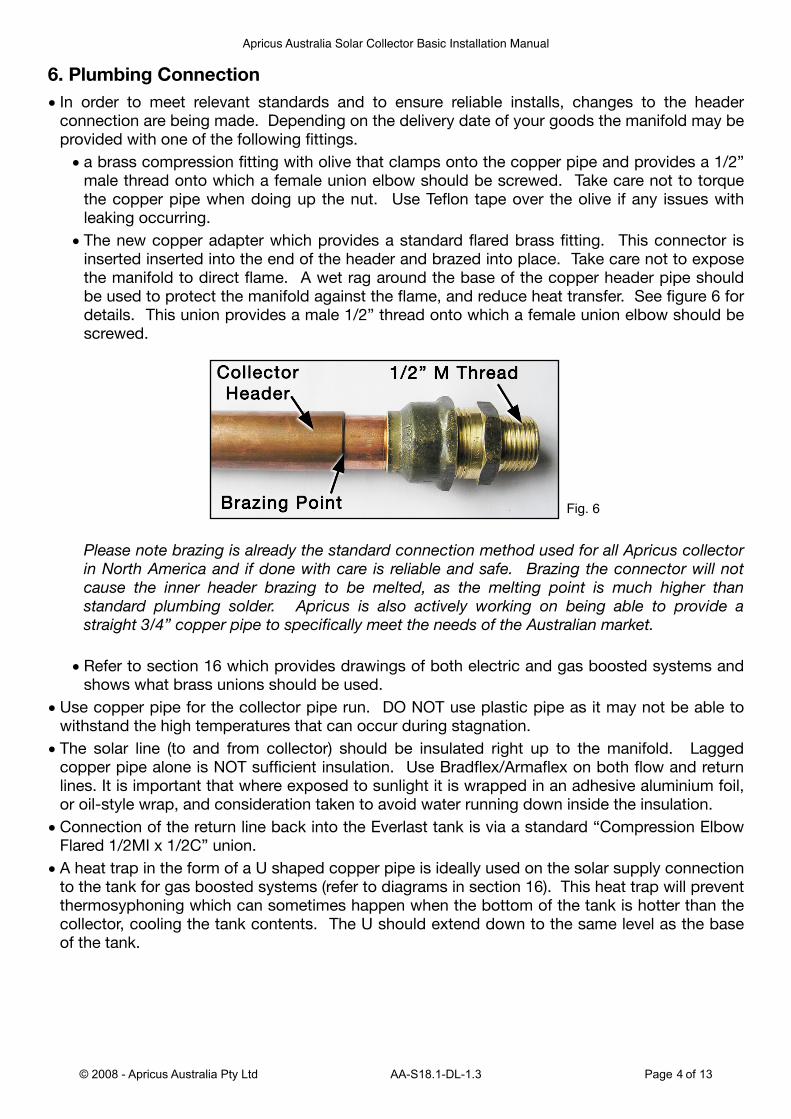
• In order to meet relevant standards and to ensure reliable installs, changes to the header connection are being made. Depending on the delivery date of your goods the manifold may be provided with one of the following fittings.
• a brass compression fitting with olive that clamps onto the copper pipe and provides a 1/2” male thread onto which a female union elbow should be screwed. Take care not to torque the copper pipe when doing up the nut. Use Teflon tape over the olive if any issues with leaking occurring.
• The new copper adapter which provides a standard flared brass fitting. This connector is inserted inserted into the end of the header and brazed into place. Take care not to expose the manifold to direct flame. A wet rag around the base of the copper header pipe should be used to protect the manifold against the flame, and reduce heat transfer. See figure 6 for details. This union provides a male 1/2” thread onto which a female union elbow should be screwed.
Please note brazing is already the standard connection method used for all Apricus collector in North America and if done with care is reliable and safe. Brazing the connector will not cause the inner header brazing to be melted, as the melting point is much higher than standard plumbing solder. Apricus is also actively working on being able to provide a straight 3/4” copper pipe to specifically meet the needs of the Australian market.
• Refer to section 16 which provides drawings of both electric and gas boosted systems and shows what brass unions should be used.
• Use copper pipe for the collector pipe run. DO NOT use plastic pipe as it may not be able to withstand the high temperatures that can occur during stagnation.
• The solar line (to and from collector) should be insulated right up to the manifold. Lagged copper pipe alone is NOT sufficient insulation. Use Bradflex/Armaflex on both flow and return lines. It is important that where exposed to sunlight it is wrapped in an adhesive aluminium foil, or oil-style wrap, and consideration taken to avoid water running down inside the insulation.
• Connection of the return line back into the Everlast tank is via a standard “Compression Elbow Flared 1/2MI x 1/2C” union.
• A heat trap in the form of a U shaped copper pipe is ideally used on the solar supply connection to the tank for gas boosted systems (refer to diagrams in section 16). This heat trap will prevent thermosyphoning which can sometimes happen when the bottom of the tank is hotter than the collector, cooling the tank contents. The U should extend down to the same level as the base of the tank.
Fig. 6
Apricus Australia Solar Collector Basic Installation Manual
© 2008 - Apricus Australia Pty Ltd AA-S18.1-DL-1.3 Page 4 of 13

7. Controller ConfigurationApricus is pleased to be introducing a much more advanced, and fully pre-wired controller. This controller provides a digital readout of the tank and collector temperatures, which is valuable both for checking system operation, and also nice for the end user.
• Figure 7.1 below shows the controller fully wired ready for installation.
• The Apricus SolaStat-Plus controller provides 3 sensors, digital temperature display and single relay for the pump.
• The pump is simply plugged into the female power port. Ensure this is positioned to avoid water ingress.
• The factory settings are suitable for most domestic installations, so no programming is required. Please refer to the instructions manual provided with the controller for more details.
• To manually run the pump (during initial testing), press and hold down PUMP button.
• To cycle through the 3 temperature readings, press the NEXT button.
Fig. 7.1
Fig. 7.2
Apricus Australia Solar Collector Basic Installation Manual
© 2008 - Apricus Australia Pty Ltd AA-S18.1-DL-1.3 Page 5 of 13
8. Temperature Sensors• The Apricus SolaStat-Plus controller is supplied with three sensor cables.
• Two short cables, INLET for the bottom of the tank, TANK for the top of the tank.
• One long cable labelled ROOF for the collector.
• The ROOF sensor is inserted into the sensor port next to the collector OUTLET, which is the higher of the two manifold pipes, and marked with the red rubber ring. Coat the sensor with a generous layer of thermal paste and insert full depth into the port. Seal up the mouth of the port with silicone sealant to avoid water ingress.
• The TANK sensor needs to read the temperature at the top of the tank. The reading does not need to be as accurate as the bottom of tank sensor, and so can simply be strapped with a pipe clamp to the hot water outlet pipe. Ensure the sensor is situated as close to the tank as possible and covered with full thickness black foam insulation. For all installations the hot water line should be insulated right up to the wall penetration as that exposed copper pipe is a significant point of heat loss.
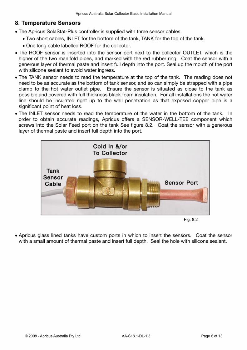
• The INLET sensor needs to read the temperature of the water in the bottom of the tank. In order to obtain accurate readings, Apricus offers a SENSOR-WELL-TEE component which screws into the Solar Feed port on the tank See figure 8.2. Coat the sensor with a generous layer of thermal paste and insert full depth into the port.
• Apricus glass lined tanks have custom ports in which to insert the sensors. Coat the sensor with a small amount of thermal paste and insert full depth. Seal the hole with silicone sealant.
Fig. 8.2
Apricus Australia Solar Collector Basic Installation Manual
© 2008 - Apricus Australia Pty Ltd AA-S18.1-DL-1.3 Page 6 of 13
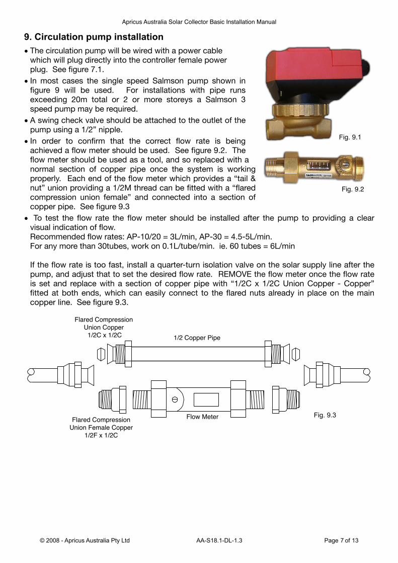
9. Circulation pump installation• The circulation pump will be wired with a power cable
which will plug directly into the controller female power plug. See figure 7.1.
• In most cases the single speed Salmson pump shown in figure 9 will be used. For installations with pipe runs exceeding 20m total or 2 or more storeys a Salmson 3 speed pump may be required.
• A swing check valve should be attached to the outlet of the pump using a 1/2” nipple.
• In order to confirm that the correct flow rate is being achieved a flow meter should be used. See figure 9.2. The flow meter should be used as a tool, and so replaced with a normal section of copper pipe once the system is working properly. Each end of the flow meter which provides a “tail & nut” union providing a 1/2M thread can be fitted with a “flared compression union female” and connected into a section of copper pipe. See figure 9.3
• To test the flow rate the flow meter should be installed after the pump to providing a clear visual indication of flow. Recommended flow rates: AP-10/20 = 3L/min, AP-30 = 4.5-5L/min. For any more than 30tubes, work on 0.1L/tube/min. ie. 60 tubes = 6L/min
If the flow rate is too fast, install a quarter-turn isolation valve on the solar supply line after the pump, and adjust that to set the desired flow rate. REMOVE the flow meter once the flow rate is set and replace with a section of copper pipe with “1/2C x 1/2C Union Copper - Copper” fitted at both ends, which can easily connect to the flared nuts already in place on the main copper line. See figure 9.3.
Fig. 9.1
Fig. 9.2
Apricus Australia Solar Collector Basic Installation Manual
© 2008 - Apricus Australia Pty Ltd AA-S18.1-DL-1.3 Page 7 of 13
Fig. 9.3
10. Bleeding Air
• Once the collector, lines and pump are connected the cold supply to the tank can be opened to fill with water. To allow filling to occur, open the hot water outlet of the tank, or a hot water tap.
• To bleed the manifold of air, loosen the fitting on the OUTLET of the manifold. Tighten once water is free-flowing without any air bubbles. The outlet is the highest of the two manifold pipes. This must be done BEFORE the tubes are installed.
• Once the system has been purged of air and circulating properly, check for any leaks at the collector, pump, tank and any other connection points.
• Check the flow rate as outlined in section 9 above.
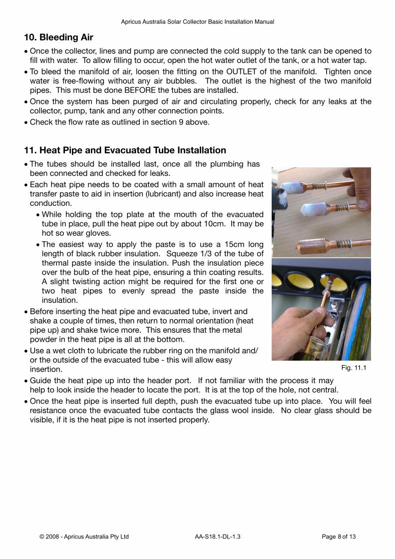
11. Heat Pipe and Evacuated Tube Installation
• The tubes should be installed last, once all the plumbing has been connected and checked for leaks.
• Each heat pipe needs to be coated with a small amount of heat transfer paste to aid in insertion (lubricant) and also increase heat conduction.
• While holding the top plate at the mouth of the evacuated tube in place, pull the heat pipe out by about 10cm. It may be hot so wear gloves.
• The easiest way to apply the paste is to use a 15cm long length of black rubber insulation. Squeeze 1/3 of the tube of thermal paste inside the insulation. Push the insulation piece over the bulb of the heat pipe, ensuring a thin coating results. A slight twisting action might be required for the first one or two heat pipes to evenly spread the paste inside the insulation.
• Before inserting the heat pipe and evacuated tube, invert and shake a couple of times, then return to normal orientation (heat pipe up) and shake twice more. This ensures that the metal powder in the heat pipe is all at the bottom.
• Use a wet cloth to lubricate the rubber ring on the manifold and/or the outside of the evacuated tube - this will allow easy insertion.
• Guide the heat pipe up into the header port. If not familiar with the process it may help to look inside the header to locate the port. It is at the top of the hole, not central.
• Once the heat pipe is inserted full depth, push the evacuated tube up into place. You will feel resistance once the evacuated tube contacts the glass wool inside. No clear glass should be visible, if it is the heat pipe is not inserted properly.
Fig. 11.1
Apricus Australia Solar Collector Basic Installation Manual
© 2008 - Apricus Australia Pty Ltd AA-S18.1-DL-1.3 Page 8 of 13
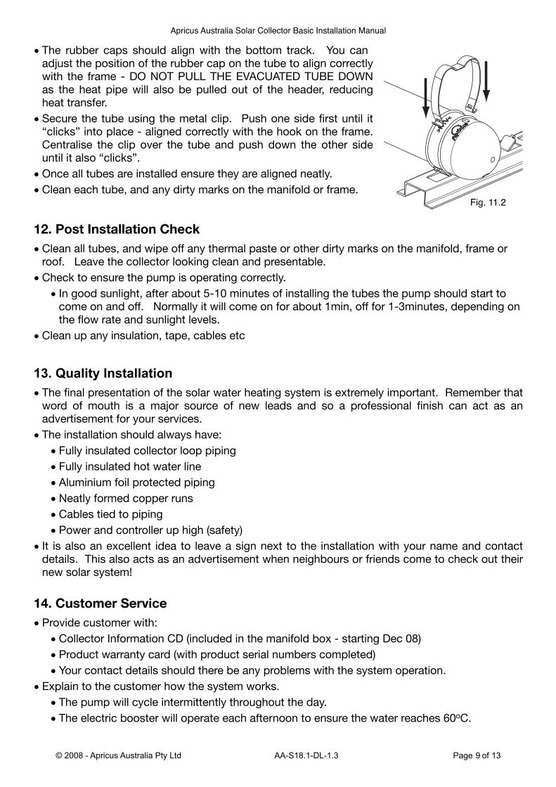
• The rubber caps should align with the bottom track. You can adjust the position of the rubber cap on the tube to align correctly with the frame - DO NOT PULL THE EVACUATED TUBE DOWN as the heat pipe will also be pulled out of the header, reducing heat transfer.
• Secure the tube using the metal clip. Push one side first until it “clicks” into place - aligned correctly with the hook on the frame. Centralise the clip over the tube and push down the other side until it also “clicks”.
• Once all tubes are installed ensure they are aligned neatly.
• Clean each tube, and any dirty marks on the manifold or frame.
12. Post Installation Check
• Clean all tubes, and wipe off any thermal paste or other dirty marks on the manifold, frame or roof. Leave the collector looking clean and presentable.
• Check to ensure the pump is operating correctly.
• In good sunlight, after about 5-10 minutes of installing the tubes the pump should start to come on and off. Normally it will come on for about 1min, off for 1-3minutes, depending on the flow rate and sunlight levels.
• Clean up any insulation, tape, cables etc
13. Quality Installation• The final presentation of the solar water heating system is extremely important. Remember that
word of mouth is a major source of new leads and so a professional finish can act as an advertisement for your services.
• The installation should always have:
• Fully insulated collector loop piping
• Fully insulated hot water line
• Aluminium foil protected piping
• Neatly formed copper runs
• Cables tied to piping
• Power and controller up high (safety)
• It is also an excellent idea to leave a sign next to the installation with your name and contact details. This also acts as an advertisement when neighbours or friends come to check out their new solar system!
14. Customer Service
• Provide customer with:
• Collector Information CD (included in the manifold box - starting Dec 08)
• Product warranty card (with product serial numbers completed)
• Your contact details should there be any problems with the system operation.
• Explain to the customer how the system works.
• The pump will cycle intermittently throughout the day.
• The electric booster will operate each afternoon to ensure the water reaches 60oC.
Fig. 11.2
Apricus Australia Solar Collector Basic Installation Manual
© 2008 - Apricus Australia Pty Ltd AA-S18.1-DL-1.3 Page 9 of 13
• Even during the summer the gas booster may come on briefly each time hot water is used as there is a small amount of cold water in the copper pipe between the tank and the booster.
• If lots of hot water is used in the evening and morning, they may run out of hot water during the day if the system is electric boosted. The booster will come on late afternoon to ensure a full tank of hot water for evening hot water usage. If they require hot water during the day, the manual over-ride on the timer can be used. Read the instructions provided in the timer manual and provide to the customer. The timer must be returned to automatic mode by the evening.
• Follow up with a courtesy phone call about one week after the installation to make sure the customer is happy and the system is working properly. Remember that word of mouth is a key source of sales inquiries.
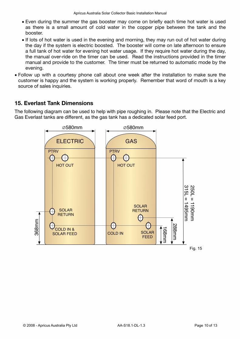
15. Everlast Tank DimensionsThe following diagram can be used to help with pipe roughing in. Please note that the Electric and Gas Everlast tanks are different, as the gas tank has a dedicated solar feed port.
168m
m
288m
m
250L =
1190m
m
315L =
1495m
m
COLD IN
SOLAR
RETURN
SOLAR
FEED
HOT OUT
PTRV
GAS
COLD IN &
SOLAR FEED
SOLAR
RETURN
HOT OUT
PTRV
ELECTRIC
368m
m
580mm580mm
Fig. 15
Apricus Australia Solar Collector Basic Installation Manual
© 2008 - Apricus Australia Pty Ltd AA-S18.1-DL-1.3 Page 10 of 13
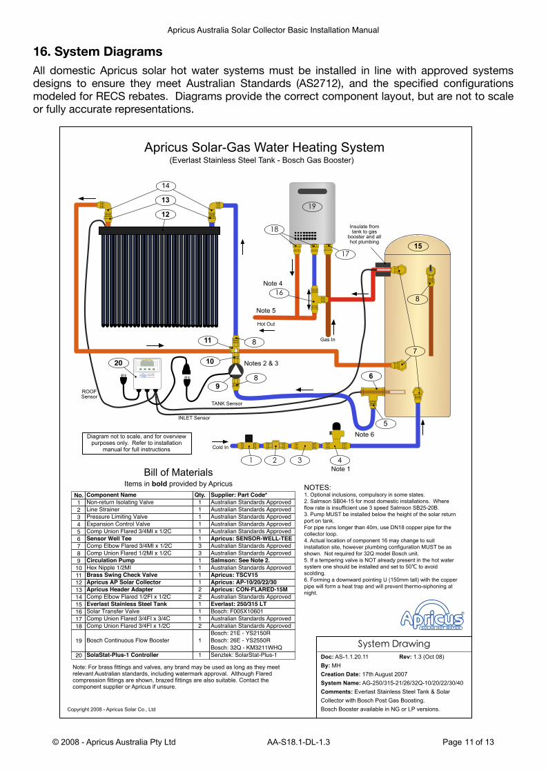
16. System DiagramsAll domestic Apricus solar hot water systems must be installed in line with approved systems designs to ensure they meet Australian Standards (AS2712), and the specified configurations modeled for RECS rebates. Diagrams provide the correct component layout, but are not to scale or fully accurate representations.
Apricus Australia Solar Collector Basic Installation Manual
© 2008 - Apricus Australia Pty Ltd AA-S18.1-DL-1.3 Page 11 of 13
Doc: AS-1.1.20.11 Rev: 1.3 (Oct 08)
By: MH
Creation Date: 17th August 2007
System Name: AG-250/315-21/26/32Q-10/20/22/30/40
Comments: Everlast Stainless Steel Tank & Solar
Collector with Bosch Post Gas Boosting.
Bosch Booster available in NG or LP versions.
!"#$%&'()*+,-.
Copyright 2008 - Apricus Solar Co., Ltd
NOTES:1. Optional inclusions, compulsory in some states.
2. Salmson SB04-15 for most domestic installations. Where
flow rate is insufficient use 3 speed Salmson SB25-20B.
3. Pump MUST be installed below the height of the solar return
port on tank.
For pipe runs longer than 40m, use DN18 copper pipe for the
collector loop.
4. Actual location of component 16 may change to suit
installation site, however plumbing configuration MUST be as
shown. Not required for 32Q model Bosch unit.
5. If a tempering valve is NOT already present in the hot water
system one should be installed and set to 50! to avoid
scolding.
6. Forming a downward pointing U (150mm tall) with the copper
pipe will form a heat trap and will prevent thermo-siphoning at
night.
Bill of Materials
Apricus Solar-Gas Water Heating System(Everlast Stainless Steel Tank - Bosch Gas Booster)
Component Name
Non-return Isolating Valve
Line Strainer
Pressure Limiting Valve
Expansion Control Valve
Comp Union Flared 3/4MI x 1/2C
Sensor Well Tee
Comp Elbow Flared 3/4MI x 1/2C
Comp Union Flared 1/2MI x 1/2C
Circulation Pump
Hex Nipple 1/2MI
Brass Swing Check Valve
Apricus AP Solar Collector
Apricus Header Adapter
Comp Elbow Flared 1/2FI x 1/2C
Everlast Stainless Steel Tank
Solar Transfer Valve
Comp Union Flared 3/4FI x 3/4C
Comp Union Flared 3/4FI x 1/2C
Bosch Continuous Flow Booster
SolaStat-Plus-1 Controller
No.
1
2
3
4
5
6
7
8
9
10
11
12
13
14
15
16
17
18
19
20
Supplier: Part Code*
Australian Standards Approved
Australian Standards Approved
Australian Standards Approved
Australian Standards Approved
Australian Standards Approved
Apricus: SENSOR-WELL-TEE
Australian Standards Approved
Australian Standards Approved
Salmson: See Note 2.
Australian Standards Approved
Apricus: TSCV15
Apricus: AP-10/20/22/30
Apricus: CON-FLARED-15M
Australian Standards Approved
Everlast: 250/315 LT
Bosch: F005X10601
Australian Standards Approved
Australian Standards Approved
Bosch: 21E - YS2150R
Bosch: 26E - YS2550R
Bosch: 32Q - KM3211WHQ
Senztek: SolarStat-Plus-1
Qty.
1
1
1
1
1
1
3
3
1
1
1
1
2
2
1
1
1
2
1
1
INLET Sensor
Gas In
Hot Out
Items in bold provided by Apricus
Diagram not to scale, and for overview purposes only. Refer to installation
manual for full instructions
TANK Sensor
Note: For brass fittings and valves, any brand may be used as long as they meet relevant Australian standards, including watermark approval. Although Flared compression fittings are shown, brazed fittings are also suitable. Contact the component supplier or Apricus if unsure.
Note 6
10
5
Insulate from tank to gas
booster and all hot plumbing
Note 1
/
12
13
14
012
20
11
9
23
24
Note 4
15
25
26
Notes 2 & 3
8
ROOFSensor
Cold In
Note 5
6
7
8
8

Apricus Australia Solar Collector Basic Installation Manual
© 2008 - Apricus Australia Pty Ltd AA-S18.1-DL-1.3 Page 12 of 13
Doc: AS-1.1.20.10 Rev: 1.3 (Nov 08)
By: MH
Creation Date: 17th August 2007
System Name: AE-250/315-10/20/30/40
Comments: Everlast Stainless Steel Electric Boosted
Tank & Solar Collector
!"#$%&'()*+,-.
Copyright 2008 - Apricus Solar Co., Ltd
NOTES:1. Optional inclusions, compulsory in some states.
2. Salmson SB04-15 for most domestic installations. Where
flow rate is insufficient use 3 speed Salmson SB25-20B.
3. Pump MUST be installed below the height of the solar return
port on tank.
For pipe runs longer than 40m, use DN18 copper pipe for the
collector loop.
4. If a tempering valve is NOT already present in the hot water
system one should be installed and set to 50! to avoid
scolding.
Bill of Materials
Apricus Solar-Electric Water Heating System(Everlast Electric Boosted Stainless Steel Tank)
Component Name
Non-return Isolating Valve
Line Strainer
Pressure Limiting Valve
Expansion Control Valve
Comp Tee Triple Flared 1/2C
Sensor Well Tee
Comp Union Flared 3/4MI x 1/2C
Comp Union Flared 1/2MI x 1/2C
Comp Elbow Flared 3/4M x 1/2C
Circulation Pump
Hex Nipple 1/2MI
Brass Swing Check Valve
Apricus AP Solar Collector
Apricus Header Adapter
Comp Elbow Flared 1/2FI x 1/2C
Everlast Stainless Steel Tank
SolaStat-Plus-1 Controller
No.
1
2
3
4
5
6
7
8
9
10
11
12
13
14
15
16
17
Supplier: Part Code*
Australian Standards Approved
Australian Standards Approved
Australian Standards Approved
Australian Standards Approved
Australian Standards Approved
Apricus: SENSOR-WELL-TEE
Australian Standards Approved
Australian Standards Approved
Australian Standards Approved
Salmson: See Note 2.
Australian Standards Approved
Apricus: TSCV15
Apricus: AP-10/20/22/30
Apricus: CON-FLARED-15M
Australian Standards Approved
Everlast: 250/315 LT
Senztek: SolarStat-Plus-1
Qty.
1
1
1
1
1
1
1
2
3
1
1
1
1
2
2
1
1
INLET Sensor
Hot Out
Items in bold provided by Apricus
Diagram not to scale, and for overview purposes only. Refer to installation
manual for full instructions
TANK Sensor
Note: For brass fittings and valves, any brand may be used as long as they meet relevant Australian standards, including watermark approval. Although Flared compression fittings are shown, brazed fittings are also suitable. Contact the component supplier or Apricus if unsure.
11
/
Note 4
Insulate hot from wall right
up to tank
Note 1
0
13
14
15
123
17
12
10
16
Notes 2 & 3
7
ROOFSensor
Cold In
6
8
9
9
9
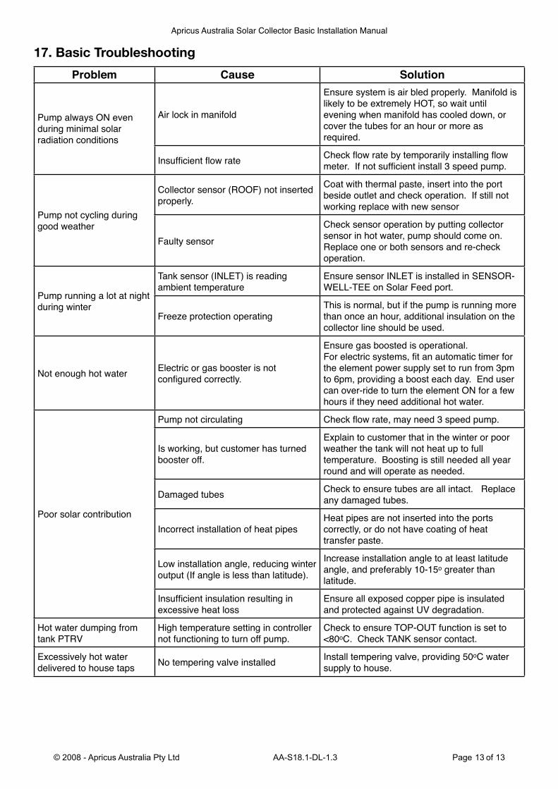
17. Basic Troubleshooting
Problem Cause Solution
Pump always ON even during minimal solar radiation conditions
Air lock in manifold
Ensure system is air bled properly. Manifold is likely to be extremely HOT, so wait until evening when manifold has cooled down, or cover the tubes for an hour or more as required.
Insufficient flow rate Check flow rate by temporarily installing flow meter. If not sufficient install 3 speed pump.
Pump not cycling during good weather
Collector sensor (ROOF) not inserted properly.
Coat with thermal paste, insert into the port beside outlet and check operation. If still not working replace with new sensor
Faulty sensorCheck sensor operation by putting collector sensor in hot water, pump should come on. Replace one or both sensors and re-check operation.
Pump running a lot at night during winter
Tank sensor (INLET) is reading ambient temperature
Ensure sensor INLET is installed in SENSOR-WELL-TEE on Solar Feed port.
Freeze protection operatingThis is normal, but if the pump is running more than once an hour, additional insulation on the collector line should be used.
Not enough hot water Electric or gas booster is not configured correctly.
Ensure gas boosted is operational.For electric systems, fit an automatic timer for the element power supply set to run from 3pm to 6pm, providing a boost each day. End user can over-ride to turn the element ON for a few hours if they need additional hot water.
Poor solar contribution
Pump not circulating Check flow rate, may need 3 speed pump.
Is working, but customer has turned booster off.
Explain to customer that in the winter or poor weather the tank will not heat up to full temperature. Boosting is still needed all year round and will operate as needed.
Damaged tubes Check to ensure tubes are all intact. Replace any damaged tubes.
Incorrect installation of heat pipesHeat pipes are not inserted into the ports correctly, or do not have coating of heat transfer paste.
Low installation angle, reducing winter output (If angle is less than latitude).
Increase installation angle to at least latitude angle, and preferably 10-15o greater than latitude.
Insufficient insulation resulting in excessive heat loss
Ensure all exposed copper pipe is insulated and protected against UV degradation.
Hot water dumping from tank PTRV
High temperature setting in controller not functioning to turn off pump.
Check to ensure TOP-OUT function is set to <80oC. Check TANK sensor contact.
Excessively hot water delivered to house taps No tempering valve installed Install tempering valve, providing 50oC water
supply to house.
Apricus Australia Solar Collector Basic Installation Manual
© 2008 - Apricus Australia Pty Ltd AA-S18.1-DL-1.3 Page 13 of 13