solar cells in action teacher and technician guide€¦ · teacher and technician guide ... 1 x...
TRANSCRIPT

Page 1
The Optoelectronics College Solar Cells in Action Activity KitTeacher and Technician Guide
The kit comprises:
5 x SEP solar investigations project pack5 x 0.22F supercapacitor (to replace 10F supercapacitor supplied with buggy)10 x 75 mm plastic wheels (to replace small rear wheels supplied with buggy)5 x DC power lead with male and female connectors5 x crocodile clip lead5 x ‘Morker’ desklamp with 25 W tungsten spotlamp1 x ‘Morker’ desklamp with 11 W fluorescent spotlamp1 x red/green/blue filter set1 x paper filter set (23 g/m2; 80 g/m2; 160 g/m2; 215 g/m2)1 x aluminium mask1 x protractor (for use in investigating the effects of illumination angles)1 x 30cm ruler (to measure lamp distances)1 x plastic box (to lift solar cell under 11W fluorescent lamp)
Schools will be expected to supply:
Metre sticks and stopwatches
The Solar Buggy

Page 2
Using the Solar Buggy
With the crocodile clip disconnected, the capacitor is charged when light falls on the solarcell and the buggy is connected to this. Unplug the buggy before running it.
Connecting the crocodile clip discharges the capacitor through the electric motor drivingthe buggy.
The solar cell
The solar cell is sensitive to infrared as well as visible light. A charging time of around1 minute allows the buggy to then move over ~1 metre, with the lamp at 15cm from thesolar cell. A fully charged capacitor allows the buggy to travel about 3 m.
The tungsten lamps should not be placed closer than 10 cm to the solar cell or the solarcells will be damaged by the heat. The 11W fluorescent lamp can come to within 5 cm ofthe solar cell, however.
The paper and card filters absorb visible light but transmit infrared which still allows thecapacitor to charge with the masks in place. The paper and card filters can be used tosimulate cloud cover. The aluminium mask absorbs both visible light and infrared.
The filters
23 g/m2 80 g/m2 160 g/m2 215 g/m2

Page 3
The lamps
Five small (Morker) desklamps are available to be used with the five solar buggies. Theseare fitted with 25 W tungsten lamps. These tungsten lamps produce most of their energyas infrared rather than visible light.
An additional small desklamp is fitted with an equivalent 11W compact fluorescent lamp.This is more suitable for use with the colour filters than the tungsten lamp due to the lackof infrared. This additional desklamp is supplied in order that pupils do not need to changebulbs if conducting an investigation into the different light sources. The lamps get very hotand there is a risk of burning.
Health and Safety Risk Assessment
Hazards and risks include: trailing leads of lamps are potential trip hazards lamps are very hot and dangerous to touch tungsten lamps should not be placed closer than 10 cm to solar cells buggies are relatively fragile and should not have loads placed on them
1 x fluorescent 5 x tungsten
Page 4
SEP Solar Buggy Instructions
On the next few pages are the instructions supplied with the Solar Buggy Kit. These areincluded for assembly information and ideas. On page 4 of the instructions, the generalidea of the solar cell with a 0.22F capacitor is outlined. This is the mode of use for thepurposes of the Optoelectronics College “Solar Cells in Action” activity.
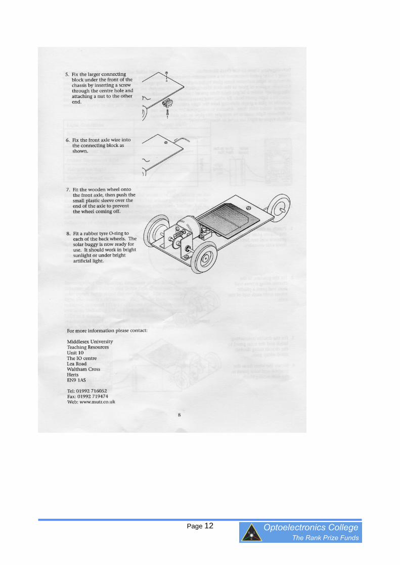
On pages 7 and 8 the assembly of the buggy is detailed and a circuit diagram given. Oneadditional modification has been made in order to enable the electric motor on the buggyto be switched on and off. Rather than connecting the red wire of the motor directly to theterminal block and capacitor a crocodile clip and additional piece of wire is connected inseries in order to make a simple switch. Details of this switch and its use are shown in thePowerpoint “Introduction to the solar buggy”.
The solar cell is used externally to the buggy and is connected to the DC power lead (plug)via the two-way terminal block supplied. DC power is supplied to the capacitor via the DCsocket and a diode, which prevents the capacitor discharging through the solar cell andalso protects the capacitor from being damaged if the wrong polarity is used. The leadwith the white stripe is connected to the central conductor of the power plug, or socket,and should be positive in polarity. The DC plug has a hole at its centre and the socket acentral conductor. Cut the power extension lead supplied at about 8 cm from the PLUGand wire this into the three-way terminal block on the buggy as shown in the buggyphotograph above. Stick the three-way terminal block onto the buggy baseboard using adouble-sided adhesive pad.
The solar cell is mounted on a panel of Corriflute plastic sheeting. Cut off the wireattached to the SOCKET about 40cm from the socket and wire the socket and the leadsfrom the solar cell into the two-way terminal block. Discard the excess wire. Stick thesolar cell and the two-way terminal block to the Corriflute panel using the double-sidedadhesive pads.
To charge the capacitor, connect the solar cell to the buggy using the DC power lead andplace the solar cell under a lamp. Once the capacitor is charged, the DC power lead isthen disconnected. The buggy can then be repositioned to allow the measurement of thedistance travelled. The buggy is set in motion by connecting the crocodile clip to the blackwire from the motor.
Connecting the buggy to the illuminated solar cell is conceptually similar to refuelling a car,except the fuel is electricity and is stored in the capacitor, rather than a fuel tank. Thesolar cell serves as the “petrol pump”.
Large wheels are provided for fitting to the driveshaft, since these improve theperformance of the buggy.
The Morker desk lamps and bulbs are provided to give a convenient and constant sourceof illumination for charging the capacitor on the buggy.
Page 5

Page 6
EAR 99
Note: The 0.22 F capacitor was obtainedfrom http://uk.digikey.com and has partnumber 283-2775-ND, seehttp://search.digikey.com/scripts/DkSearch/dksus.dll?Detail?name=283-2775-ND
0.22 Farad, 2.5V

Page 7

Page 8
Note: The buggy kit contains a 10 Fcapacitor. This makes the buggy runslowly and take a long time to stop.Please discard this and use the 0.22 Fcapacitor supplied separately.

Page 9

Page 10
Note: Different colour LEDs mayhave different light intensities. Lowvoltage LEDs can be used withseries ballast resistors and thevalues of these can be adjusted toequalise their light outputs, however.[Using the fluorescent lamp andcolour filters supplied will givereasonable results more cheaply andeasily than LEDs.]

Page 11
Note: The capacitor, diode andcrocodile clip lead should be wired intothe connecting block, as shown below:
M+
Crocclip
Solarcell
Energystoragedevice
Diode(to block
reverse current)
DC power jack BUGGY
Note: Use the larger 75mm wheelson the drive axle instead of the smallerones. This will enhance theperformance of the buggy.
Page 12
Page 13
Performance of the Solar Buggy
It is recommended that each buggy in the kit is numbered and the groups of pupils alwayswork with the same buggy. The exact performance of each buggy varies significantly dueto different performance of solar cell and resistive forces on motor, gears and wheels.
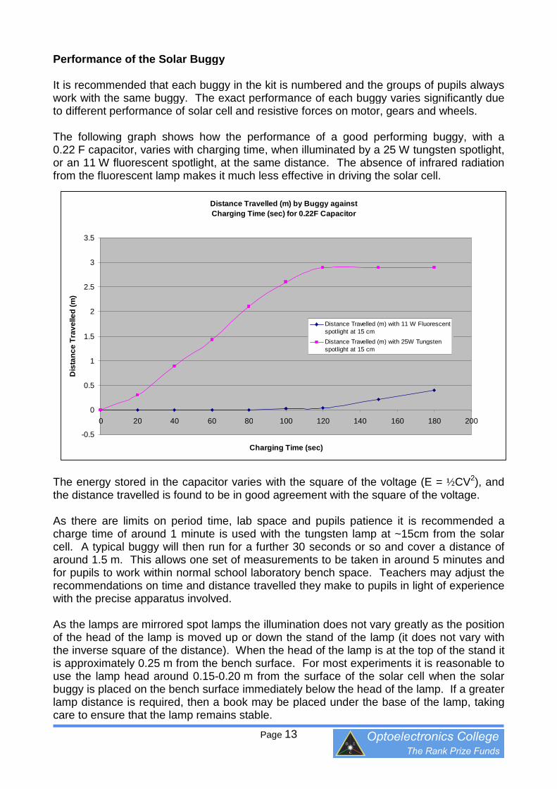
The following graph shows how the performance of a good performing buggy, with a0.22 F capacitor, varies with charging time, when illuminated by a 25 W tungsten spotlight,or an 11 W fluorescent spotlight, at the same distance. The absence of infrared radiationfrom the fluorescent lamp makes it much less effective in driving the solar cell.
The energy stored in the capacitor varies with the square of the voltage (E = ½CV2), andthe distance travelled is found to be in good agreement with the square of the voltage.
As there are limits on period time, lab space and pupils patience it is recommended acharge time of around 1 minute is used with the tungsten lamp at ~15cm from the solarcell. A typical buggy will then run for a further 30 seconds or so and cover a distance ofaround 1.5 m. This allows one set of measurements to be taken in around 5 minutes andfor pupils to work within normal school laboratory bench space. Teachers may adjust therecommendations on time and distance travelled they make to pupils in light of experiencewith the precise apparatus involved.
As the lamps are mirrored spot lamps the illumination does not vary greatly as the positionof the head of the lamp is moved up or down the stand of the lamp (it does not vary withthe inverse square of the distance). When the head of the lamp is at the top of the stand itis approximately 0.25 m from the bench surface. For most experiments it is reasonable touse the lamp head around 0.15-0.20 m from the surface of the solar cell when the solarbuggy is placed on the bench surface immediately below the head of the lamp. If a greaterlamp distance is required, then a book may be placed under the base of the lamp, takingcare to ensure that the lamp remains stable.
Distance Travelled (m) by Buggy against
Charging Time (sec) for 0.22F Capacitor
-0.5
0
0.5
1
1.5
2
2.5
3
3.5
0 20 40 60 80 100 120 140 160 180 200
Charging Time (sec)
Dis
tan
ce
Tra
ve
lle
d(m
)
Distance Travelled (m) with 11 W Fluorescentspotlight at 15 cm
Distance Travelled (m) with 25W Tungstenspotlight at 15 cm

Page 14
Before conducting any experiments, the pupils must connect the crocodile clip switch andallow the buggy to run to a standstill. When the buggy runs to a standstill the crocodile clipshould be disconnected immediately. It is convenient to consider the capacitor thendischarged and take this as an effective zero point (the capacitor is not actually fullydischarged, but its voltage of ~0.5V and the energy stored are insufficient to drive thebuggy against the resistive forces). Light then falling on the solar cell will cause thecapacitor to charge from this ‘zero’ and result in the solar buggy moving a distance. Thiscan be investigated as part of the recommended Lesson 1 in the teaching sequence inorder to familiarise the pupils in the operation of the buggy before their formal investigationin Lesson 2.
The 11 W fluorescent spotlight is used because it emits very little near infrared radiation,which would swamp any measurements of spectral sensitivity. Because of this, it is lesseffective in energising the solar cell and it should be used at a distance of ~5 cm from thesolar cell and the capacitor charged for 4 minutes. This can be achieved by raising thesolar cell on the plastic box provided and then adjusting the lamp height. When thefluorescent lamp is used with the colour filters, the performance is as follows:
This illustrates that the solar cell is more sensitive to red light than to green, or blue, light.This is because the solar cell has its peak sensitivity in the near infrared. [The “No Filter”bar is shown for information only.]
Distance Travelled (m) by Buggy against filter used
with 11W Fluorescent Spotlight at 5 cm for 4 minutes and 0.22F Capacitor
0
0.5
1
1.5
2
2.5
No filter Red filter Green filter Blue filter
Filter Condition
Dis
tan
ce
Tra
vell
ed
(m)