soil testing criteria
TRANSCRIPT

Soil Testing Criteria
Introduction Understanding the character and permeability of surface and subsurface soils at a proposed land development site is crucial to the design of stormwater best management practices (BMP) that meet the requirements of the NJDEP’s Stormwater Management Rules (NJAC 7:8). In particular, a soil’s response to rainfall, measured by its ability to absorb and infiltrate some of that rainfall, is a required input parameter when computing both pre- and post-developed site runoff and recharge rates. Similarly, a soil’s permeability is a critical parameter in the design of stormwater BMPs that utilize infiltration. Presented below are three sets of guidelines: Section 1 demonstrates how to identify an appropriate Hydrologic Soil Group (HSG) for a soil with an unknown or questionable HSG including a method to identify an appropriate soil series name for an unknown or questionable soil for use in the New Jersey Groundwater Recharge Spreadsheet (NJGRS); Section 2 and 3 contains detailed field and laboratory testing procedures for determining the permeability rates of soils beneath a proposed infiltration BMP; and Section 4 contains construction oversight guidance and post-construction standards for both determining and evaluating soil permeability beneath a newly constructed infiltration BMP.
All soil profile pits, soil borings, and soil permeability tests and associated documentation shall be conducted under the direct supervision of licensed New Jersey professional engineer. During all subsurface investigations and soil test procedures, adequate measures shall be taken to ensure personnel safety and prohibit unauthorized access to the excavations at all times. Entering a soil pit excavated below the water table can be extremely dangerous and should be avoided unless the pit is relatively shallow and the sides of the pit have been stepped and sloped to eliminate the likelihood of sudden and severe cave-in of the pit.
It is the responsibility of the company or persons performing or witnessing subsurface investigations and soil permeability tests to comply with all applicable Federal, State and local laws and regulations governing occupational safety, including but not limited to the requirements of N.J.A.C. 7:9A-5.2(e)3. This guidance cannot be construed to indicate that it contains the required soil testing to assess hydraulic impacts on groundwater from infiltration. Additional soil information may be necessary depending on the type of mounding analysis and the specific site being assessed. The design engineer shall ensure that there is no adverse impact to other properties due to infiltration.
September 2009 Page E-1
1. Methods for Identifying HSGs
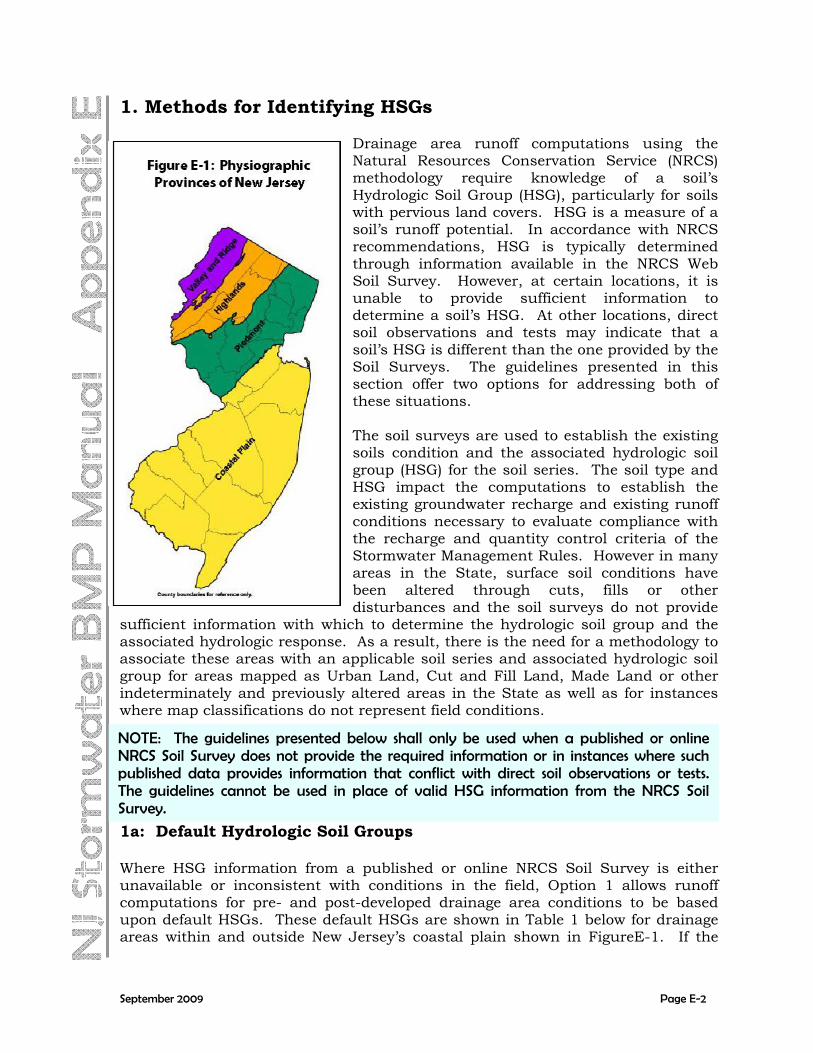
Drainage area runoff computations using the Natural Resources Conservation Service (NRCS) methodology require knowledge of a soil’s Hydrologic Soil Group (HSG), particularly for soils with pervious land covers. HSG is a measure of a soil’s runoff potential. In accordance with NRCS recommendations, HSG is typically determined through information available in the NRCS Web Soil Survey. However, at certain locations, it is unable to provide sufficient information to determine a soil’s HSG. At other locations, direct soil observations and tests may indicate that a soil’s HSG is different than the one provided by the Soil Surveys. The guidelines presented in this section offer two options for addressing both of these situations. The soil surveys are used to establish the existing soils condition and the associated hydrologic soil group (HSG) for the soil series. The soil type and HSG impact the computations to establish the existing groundwater recharge and existing runoff conditions necessary to evaluate compliance with the recharge and quantity control criteria of the Stormwater Management Rules. However in many areas in the State, surface soil conditions have been altered through cuts, fills or other disturbances and the soil surveys do not provide
sufficient information with which to determine the hydrologic soil group and the associated hydrologic response. As a result, there is the need for a methodology to associate these areas with an applicable soil series and associated hydrologic soil group for areas mapped as Urban Land, Cut and Fill Land, Made Land or other indeterminately and previously altered areas in the State as well as for instances where map classifications do not represent field conditions.
1a: Default Hydrologic Soil Groups
NOTE: The guidelines presented below shall only be used when a published or online NRCS Soil Survey does not provide the required information or in instances where such published data provides information that conflict with direct soil observations or tests. The guidelines cannot be used in place of valid HSG information from the NRCS Soil Survey.
Where HSG information from a published or online NRCS Soil Survey is either unavailable or inconsistent with conditions in the field, Option 1 allows runoff computations for pre- and post-developed drainage area conditions to be based upon default HSGs. These default HSGs are shown in Table 1 below for drainage areas within and outside New Jersey’s coastal plain shown in FigureE-1. If the
September 2009 Page E-2

designer engineer does not wish to utilize these assumed hydrologic soil groups, a process is outlined below to establish the HSG based on site-specific investigation. 1b: Hydrologic Soil Group Testing Procedures Number and Location of Soil Explorations: On those areas of the development parcel for which the HSG is either unknown or inaccurate with respect to field conditions, a minimum of one (1) soil profile pit and four (4) soil borings shall be conducted within each soil mapping unit of one half (0.5) acre or more and less than two (2) acres shown on the NRCS Web Soil Survey. Where the HSG is unknown for a mapping unit of less than one half (0.5) acre, a minimum of one soil profile pit and one soil boring shall be conducted within that mapping unit. The purpose of each soil profile pit is to establish detailed information on groundwater conditions and soil morphology. Data recorded in each soil boring is to be compared to the reference soil profile pit to confirm consistence between the profile pit and the boring. Where soil and/or groundwater properties vary significantly between soil boring and profile pit explorations, additional soil profile pits shall be conducted as necessary to resolve such differences and accurately characterize the mapping unit’s soils.
Table 1: Default Hydrologic Soil Groups for Runoff Computations
Site Location within New Jersey Site Condition In Coastal
Plain Outside Coastal
Plain Pre-Developed HSG A HSG B
Post-Developed
HSG D HSG D
Where the HSG is unknown for a mapping unit larger than two (2) acres within the
limits of the overall site, a minimum of one (1) additional soil profile pit and two (2) additional soil borings shall be conducted for each additional two (2) acres. All soil explorations shall be located generally equidistant from each other and the boundaries of the mapping unit to maximize the ability to interpolate between test locations so as to provide adequate characterization of the mapping unit’s soil. In all cases, a soil profile pit may be conducted in place of a required soil boring; however, a soil boring cannot be used as a substitute for a soil profile pit except as stated below.
In areas where a soil profile pit would substantially disturb the existing area and create an undesirable condition or where significant environmental disturbance
September 2009 Page E-3

will occur in an area that is not intended for future development, two soil borings may be conducted in the place of a required soil profile pit with a soil profile pit located at the closest available location representative of the soil boring locations. If the location of the soil profile pit is not representative of the soil borings taken, it is the responsibility of the design engineer to demonstrate the consistency of soil profile pit data to the soil characteristics at the location of the soil borings. Where soil and/or groundwater properties vary significantly between soil explorations, additional soil profile pits shall be conducted as necessary to resolve such differences and accurately characterize the mapping unit’s soils.
Table 2: Default Soil Series for NJGRS Recharge
Computations
Hydrologic Soil Group
Default Soil Series Name
A Fort Mott B Nixon C Venango D Any D soil
Soil profile pits and soil borings performed for the purpose of determining HSG shall extend to the depth of the seasonal high water table or the deeper of six (6) feet below existing grade or four (4) feet below proposed grade. The determination of soils HSG is based upon the depth to restrictions (i.e. soil morphological characteristics which restrict the vertical movement of water including but not limited to abrupt textural boundaries, fragipan, bedrock, dense or cemented soils, and the depth to the seasonally high water table (SHWT)) and the permeability rate of the most restrictive soil horizon above either the restriction or the SHWT. The presence and depth of these restrictions must be included in the soil log of both the soil profile pits and the soil borings. Information to be included in the soil logs are provided in Section 3 below. The following guidance documents from the USDA Natural Resources Conservation Service should be utilized to establish the hydrologic soil groups:
USDA Natural Resources Conservation Service. “Part 630 Hydrology National Engineering Handbook Chapter 7 Hydrologic Soil Group”, May 2007.
USDA Natural Resources Conservation Service. National Soil Survey Handbook, “Part 618.49 Restriction Kind, Depth, Thickness, and Hardness,” pp 618-33 to 618-34, 1996.
The Department summary of the NRCS guidance documents to establish hydrologic soil group based on permeability rates is provided in the Addendum at the end of this document.
1c: Default Soil Series for NJGRS Recharge Computations The design of infiltration BMPs for groundwater recharge using the New Jersey Groundwater Recharge Spreadsheet (NJGRS) requires knowledge of a soil’s series name, which is used by the NJGRS to compute the soil’s infiltration and recharge capabilities. Soil series name is typically determined through information available
September 2009 Page E-4

in the published NRCS County Soil Surveys. However, these guidelines have been developed where the County Soil Surveys are unable to provide sufficient information at a particular site or where on-site soil observations or tests may indicate that a soil’s series name is different than the one provided by a Soil Survey. The guidelines presented in this section have been developed to address both of these situations. Once the hydrologic soil group (HSG) is known as provided above, the default soil series shown in Table 2 may be used in the NJGRS.
NOTE: The default soil series in Table 2 are only for the use in the New Jersey Groundwater Recharge Spreadsheet and are not an indication of the soil series that may actually exist within a hydrologic soil group at a site. Additional soil testing and characterization may be needed if the actual soil series type is necessary.
2. Soil Tests for Infiltration BMPs The design of a stormwater infiltration BMP, either for groundwater recharge, stormwater quality, or stormwater quantity purposes, requires specific knowledge of the permeability and related characteristics of each of the soil layers beneath the proposed BMP. Stormwater infiltration BMPs are those BMPs which rely on infiltration for groundwater recharge, stormwater runoff quality, and/or stormwater runoff quantity control. Examples include, but are not limited to, bioretention system without underdrain, dry well, infiltration basin, and sand filter without underdrain. As described in Chapter 9.5 of the New Jersey Stormwater Best Management Practices (BMP) Manual, these soil permeabilities must meet or exceed certain minimum rates. This section presents soil testing guidelines to determine soil permeabilities at proposed stormwater infiltration BMPs. Number and Location of Soil Explorations: Soil profile pit and soil borings are only required in the areas of the BMP being utilized for infiltration, also referred to as a BMP’s infiltration area. Where the entire bottom of a BMP is being utilized for infiltration, the infiltration area will be equal to the entire bottom area. Where only a portion of the BMP’s bottom is being utilized for infiltration, the infiltration area is applicable only to that portion of the BMP.
In areas where a soil profile pit would substantially disturb the existing area and create an undesirable condition or where significant environmental disturbance will occur in an area that is not intended for future development, two soil borings may be conducted in the place of a required soil profile pit with a soil profile pit located at the closest available location representative of the soil boring locations. If the
September 2009 Page E-5

location of the soil profile pit is not representative of the soil borings taken, it is the responsibility of the design engineer to demonstrate the consistency of soil profile pit data to the soil characteristics at the location of the soil borings. Generally, a minimum of two (2) soil profile pits shall be excavated within the infiltration area of any proposed infiltration BMP to determine the suitability and distribution of soil types present at location of the BMP. Placement of the test pits shall be such that it provides adequate characterization of the infiltration area. For BMP infiltration areas larger than ten thousand (10,000) square feet in area, a minimum of one (1) additional soil profile pit shall be conducted for each additional area of ten thousand (10,000) square feet. The total number of required soil profile pits shall be placed generally equidistant from each other so as to provide adequate characterization of the infiltration area. For sites with multiple infiltration BMPs each with surface areas less than 500 square feet, a minimum of one (1) soil profile pit is required for the site and one soil boring per infiltration BMP. In doing so, the test pit must be properly located within the overall site to adequately depict site soil conditions. Where soil and/or groundwater properties vary significantly between soil explorations, additional soil profile pits shall be conducted as necessary to resolve such differences and accurately characterize the mapping unit’s soils. For drywells associated with single family residential development, only one soil boring is required per lot. A linear BMP is defined as a BMP with the following characteristics:
- Possesses a minimum infiltration area length to width ratio of 4 to 1; and
- Is limited to a maximum infiltration area bottom width of twenty-five (25) feet and a maximum infiltration area top width of forty (40) feet.
For linear infiltration BMPs, a minimum of one soil profile pit shall be conducted within each soil mapping unit for the first 500 linear feet. Where the distance exceeds 500 feet within the same mapping unit, soil boring shall be conducted for
September 2009 Page E-6

every 500 feet and a soil profile pit shall be conducted for every 2000 feet. The total number of required soil explorations shall be placed generally equidistant from each other so as to provide adequate characterization of the infiltration area. These requirements are illustrated in Figure E-4.
Where soil and/or groundwater properties vary significantly between soil explorations, additional soil profile pits shall be conducted as necessary to resolve such differences and accurately characterize the subsurface conditions below the infiltration BMP. Soil explorations (soil profile pits and soil borings) shall extend to a minimum depth of eight (8) feet below the lowest elevation of the basin bottom or to a depth that is at least two (2) times the maximum potential water depth in the proposed BMP, whichever is greater. Soil permeability tests shall be conducted on the most hydraulically restrictive horizon or substratum to be left in place below the BMP as follows: Where no soil replacement below the bottom of the BMP is proposed, the permeability tests shall be conducted on the most hydraulically restrictive horizon or substratum above the SHWT or bedrock within eight (8) feet of the lowest elevation of the basin bottom or to a depth equal to two (2) times the maximum potential water depth within the basin, whichever is greater. Where soil replacement below the bottom of the BMP is proposed, the permeability tests shall be conducted within the most hydraulically restrictive horizon or substratum below the depth of soil replacement and above the SHWT or bedrock to a depth equal to two (2) times the maximum potential water depth within the basin or eight feet below the elevation of the basin bottom, whichever is greater. Permeability tests may be performed on the most hydraulically restrictive soil horizons or substrata at depths greater than those identified above.
September 2009 Page E-7

Stormwater infiltration BMPs shall not be installed in soils that exhibit artesian groundwater conditions. Please refer to N.J.A.C 7:9A-5:8 to recognize the zone of saturation. A hydraulic head test, as defined at N.J.A.C. 7:9A-5.9 shall be conducted in all soils that immediately underlie a perched zone of saturation to determine whether an artesian condition exists. Stormwater infiltration BMPs relying on fractured bedrock for exfiltration shall not be installed without a minimum of two feet between the bottom of the infiltration basin and the bedrock. Where the permeability rate of the bedrock is critical to the function of the basin, the design engineer shall demonstrate that appropriate testing methods as discussed in Section 3a are utilized to establish the permeability rates of the infiltration basin. The number of permeability tests shall be no less than the tests required for permeability in the soil.
3. Soil Permeability Testing 3a. Soil Tests A minimum of one (1) permeability test shall be performed at each soil profile pit and soil boring location. Permeability rates can be determined as described in the Addendum using the Tube Permeameter Test, the Percolation Test, Pit Bailing Test or Basin flooding test (for bedrock). Also ASTM D 3385 (Double-Ring infiltrometer), USBR 7300-89 (Well Permeameter Method), or other Constant head permeability tests that utilize in-situ conditions and accompanied by a recognized published source reference can be used for establishing the permeability rates. When performing a soil boring during soil investigation, the borings shall be performed and reported in accordance with ASTM D 1452 Practice for Soil Investigation and Sampling Auger Borings & ASTM D 1586 - Test Method for Penetration Test and Split-Barrel Sampling of Soils. Sampling shall be continuous for the entire depth of the boring to fully characterize the soil profile. Permeability Testing in Bedrock The number of permeability tests for bedrock shall be no less than the tests required for permeability in the soil. The design permeability rate of 0.5 in/hr can be used for bedrock when the basin drains completely within 12 hours during a basin flood test performed as described in the Addendum. To use permeability rates greater than 0.5 in/hr, more detailed testing is required. USBR 7300-89 or pump tests shall be utilized for detailed investigation. 3b. Soil Logs A soil log shall be prepared for each soil profile pit and soil boring. The soil boring log shall, at a minimum, provide the following:
September 2009 Page E-8

- elevation of the existing ground surface and elevations of permeability test locations;
- the depth and thickness of each soil horizon and the depth to the substratum; - the dominant matrix or background and mottle colors using the Munsell
system of classification for hue, value and chroma; - the appropriate textural class as shown on the USDA textural triangle; the
volume percentage of coarse fragments larger than two (2) millimeters in diameter; the abundance, size, and contrast of mottles;
- the soil moisture condition, using standard USDA classification terminology; - the presence of any soil horizon, substratum or other feature that exhibits an
in-place permeability rate less than one (1) inch per hour; the depth and occurrence of soil restrictions including, but not limited to, abrupt textural boundaries likely to restrict the movement of water, fragipans, dense materials, bedrock, and ortstein;
- the depth to the seasonally high ground water level, either perched or regional; - the static (stabilized) water level, presence of soil mottles or other
redoximorphic features; and - any observed seepage or saturation.
In addition to all of the above the soil profile pit log shall also provide the soil structure and soil consistence using standard USDA classification terminology.
The results and locations of all soil profile pits, borings and soil permeability tests, both passing and failing, shall be included in the Stormwater Management Report submitted to the appropriate review agency.
September 2009 Page E-9

4. Construction and Post-Construction Oversight and Soil Permeability Testing 4a. Construction During construction, regular oversight should be provided by the professional engineer responsible for ensuring the effectiveness of infiltration BMPs to ensure that the basin functions as designed. Oversight includes, but is not limited to, the following:
Participation in a pre-construction meeting with the contractor to ensure their familiarity with the special care necessary in constructing an infiltration BMP.
Confirmation of the proper use of construction equipment. Minimize the
compaction of the infiltration area.
Ensuring that the earthwork does not occur on the BMP when the soil moisture content is above the lower plastic limit and that the specifications of the replacement soil are met.
Testing each soil layer where the permeability rate is critical prior to the
placement of a new layer to ensure that the permeability rate has been retained. For example, in bioretention-infiltration basins, the subsoil should be tested prior to the placement of the soil filter media.
Ensuring that proper precautions are taken to prevent sediment entering
the infiltration area during construction or where unavoidable, if the basin is used as a sedimentation basin, excavation for sediment basin is at least two (2) feet above the final design elevation of the basin bottom.
4b. Post-Construction Post-construction soil permeability tests should be conducted within the most hydraulically restrictive soil horizon or substratum between the bottom of the as-built BMP and the seasonal high groundwater table to ensure that the installed BMP functions as designed. Such testing should be carefully undertaken when all BMP construction that may affect soil permeability has been completed. This includes the use of all construction equipment and the placement of all construction material that may affect soil permeability. In addition, hand tools and manual permeability test procedures shall be used to avoid effecting soil permeability. If the post-construction field-tested permeability rates (reduced by a safety factor of 2) confirm the BMP’s ability to totally drain within 72 hours after the cessation of the design storm, the infiltration BMP’s drain time is acceptable. If this required drain time cannot be achieved based on the permeability rates alone, the applicant has the option to demonstrate that the infiltration BMP, when flooded with water
September 2009 Page E-10

either artificially or naturally by rain event, performs as designed for infiltration. If neither the testing or flooding of the basin works then the soils below the infiltration BMP must be renovated or replaced and then re-tested until the required drain time is achieved. Similar to the soil permeability tests performed during construction, all post-construction soil permeability test results shall be certified by a licensed professional engineer. A minimum of two permeability test shall be performed within the infiltration area of the as-built BMP. For BMPs with infiltration area larger than ten thousand square feet, a minimum of one additional permeability test shall be conducted for each additional ten thousand square feet. The permeability tests shall be performed at locations so as to provide adequate characterization of the infiltration area. For multiple infiltration BMPs with surface areas less than 500 square feet, one permeability test must be performed at the location of each BMP For linear infiltration BMPs, a minimum of two permeability test shall be conducted within each soil mapping unit within the BMP’s infiltration area. Where the distance in the same mapping unit exceeds 500 feet, one additional permeability test shall be performed for every five hundred feet. The permeability tests shall be performed at locations so as to provide adequate characterization of the infiltration area.
DEFINITIONS “Significant changes” means a difference in soil permeability that would result in a significant change in the design of the stormwater infiltration BMP. “Soil Profile Pit” means an excavation made for the purpose of exposing a soil profile which is to be described. “Soil Profile” means a vertical cross-section of undisturbed soil showing the characteristic horizontal layers or horizons of the soil which have formed as a result of the combined effects of parent material, topography, climate, biological activity and time. “Soil log” means a description of the soil profile which includes the depths, thickness, color, texture, coarse fragment content, mottling, structure and consistence of each soil horizon or substratum.
September 2009 Page E-11

ADDENDUM
This addendum provides the Department summary of the NRCS guidance documents to establish hydrologic soil group based on permeability rates and the procedures for a Percolation test, a Pit-bailing test, a Tube permeameter test and a Basin flooding test mentioned in Section 3a . A. Summary of NRCS Guidance Documents to Establish HSG Restrictions are based on the conditions that comply with the definition of restriction in the 1996 National Soil Survey Handbook and include, but are not limited to the presence of bedrock, dense material, fragipans, and ortsteins. The SHWT shall be based either observed saturation or redoxomorphic features. If a layer of restriction is found in the upper 20 inches or if the seasonally high water table (SHWT) is within the upper 24 inches, the soil should be classified as HSG D. If the restriction or SHWT is at 20 – 40 inches below grade, the first column of Table 1 shall be utilized to establish the hydrologic soil group (HSG). If no SWHT or restriction is found in the upper 40 inches, the second column of Table 1 shall be used to establish the HSG. The lowest permeability rate of the area above the restriction or of the top 40 inches, if no restriction is found, must be compared with the values in Table 1 to establish the HSG.
Table 1. Permeability Rates for Hydrologic Soil Groups Based on Lowest Permeability Rate (Most Restrictive Soil Layer)
Restriction at
20-40” Restriction at 40" or greater
in/hr in/hr HSG A >5.67 >1.42 HSG B 1.42 - 5.67 0.57 – 1.42 HSG C .14 - 1.42 0.06 – 0.57 HSG D <= 0.14 <=0.06
HSG D if depth to most restrictive layer is less than 20" or depth to SHWT < 24 inches.
Restriction includes, but is not limited to, abrupt textural boundary, fragipan, bedrock, dense material or ortstein.
September 2009 Page E-12

B. Procedures for Permeability Testing
The following methods provide details of the permeability testing that were cited in Section 3a above.
B1. Percolation Test
A percolation test can be utilized to establish the permeability rates of soils provided that that percolation test results is adjusted to permeability rate in accordance to ‘e’ below. Percolation tests shall not be conducted in frozen ground or in holes which have been allowed to remain open to the atmosphere for periods greater than three days. The required configuration of the test hole is illustrated in Figure 1. a. Equipment Requirements
The following equipment is required for the percolation test: o A soil auger, post-hole digger or other means of preparing a test hole as
prescribed below; o A knife or trowel for removing smeared or compacted surfaces from the
walls of the test hole; o Fine (from two to 10 millimeter in diameter) gravel (optional); o A water supply (50 gallons is generally adequate); o A straight board (to serve as fixed reference point for water level
measurements); o A clock and a ruler (12 inches or longer, engineering scale); o An automatic siphon or float valve (optional); and o A hole liner consisting of a 14 inch section of slotted pipe or well screen,
or a 14 inch length of one-quarter inch hardware cloth or other similar material rolled into a tube (optional). The hole liner shall be no smaller than two inches in diameter less than the test hole.
b. Test Hole Preparation
The test hole shall be prepared in accordance with the following:
Step One: Excavate a test hole with horizontal dimensions of eight to 12 inches at a depth such that the lower six inches of the test hole are contained entirely within the soil horizon or layer of fill material being tested. In order to facilitate access to the lower portion of the hole, the test hole may be excavated from the bottom of a shallow pit provided that the vertical axis of the test hole is a minimum of 14 inches measured from the bottom of the pit to the bottom of the test hole.
Step Two: In soil textures other than sands or loamy sands, remove smeared or compacted soil from the sides and bottom of the test hole by inserting the tip of a knife or trowel into the soil surface and gently prying upward and outward. Remove loose soil from the test hole.
September 2009 Page E-13

Figure 1: Percolation Test
Step Three: At this point, a one-half inch layer of fine gravel may be placed in the bottom of the hole to protect the soil surface from disturbance or siltation when water is added to the hole. If additional protection is desired, a hole liner as described in (a) above may be placed in the hole and the space between the liner and the sides of the hole may be filled with fine gravel.
Step Four: Place and secure a straight board horizontally across the top of the test hole, as shown in the figure, to serve as a fixed point for depth of water measurements to be made at appointed time intervals throughout the test.
c. Pre-Soaking of Soils
All soils, except for sandy textured soils which meet the requirements below, shall be pre-soaked using the following procedure. Any soil which exhibits cracks or fissures between soil aggregates shall be pre-soaked in the following manner regardless of the texture.
1. Fill the test hole with water and maintain a minimum depth of 12 inches
for a period of four hours by refilling as necessary or by means of an automatic siphon or float valve.
2. At the end of four hours, cease adding water to the hole and allow the
hole to drain for a period of from 16 to 24 hours. In sandy textured soils, including sands, loamy sands and sandy loams, where a rapid percolation rate is anticipated, fill the test hole to a depth of
September 2009 Page E-14

12 inches and allow to drain completely. Refill the hole to a depth of 12 inches and record the time required for the hole to drain completely. If this time is less than 60 minutes, the test procedure may begin as prescribed in (d) below without further pre-soaking. If water remains in the test hole after 60 minutes, the hole must be pre-soaked as prescribed above before proceeding with the test.
d. Percolation Rate Determination
Immediately following the pre-soak procedure (no more than 28 hours after the start of the pre-soak procedure), the percolation rate shall be determined using the following procedure: Step One: If water remains in the test hole after the completion of the pre-soak period, the test shall be terminated and the percolation rate shall be reported as greater than 60 minutes per inch. If no water remains in the test hole, fill to a depth of seven inches. At a five to 30 minute time interval, depending upon the rate of fall, record the drop in water level to the nearest one-tenth of an inch. Refill the hole at the end of each time interval and repeat this procedure using the same time interval until a constant rate of fall is attained. A constant rate of fall is attained when the difference between the highest and lowest of three consecutive measurements is no greater than two-tenths of an inch.
Step Two: Immediately after the completion of Step One, refill the test hole to a depth of seven inches and record the time required for exactly six inches of water to seep away. This time divided by six will be the percolation rate in minutes per inch.
e. Permeability Rate Determination
The permeability rate shall be established from the results of the percolation rate based on the following procedures. When the purpose of the test is to determine the permeability at the level of infiltration, the slowest percolation rate determined shall be used as a field measured percolation rate. If any of the measured percolation rates are slower than 60 minutes per inch, then this method shall not be utilized. The percolation test results shall only be used if the percolation rate is 60 minutes per inch or faster. The field measured hydraulic conductivity value shall be calculated using Equation 1 below:
Table 2: Parameter ‘a’ Values
for Equation 1 Bottom Width
(inch) Parameter
‘a’ 8 22 9 23.5 10 25 11 26.3 12 27.5
hrinp
aK
m
/ [Equation 1]
Where pm = percolation rate in minutes per inch
a = parameter from the Table 2 (depending on the bottom width of the percolation hole)
September 2009 Page E-15

B2.Pit-bailing test
A pit-bailing test (shown in Figure 2) can be utilized to establish the permeability rates of soils in accordance to the procedures below.
a. Equipment Requirements
The following equipment is required for performing a pit-bailing test: o A back-hoe; o Wooden or metal stakes, string and a hanging level; o A steel measuring tape; o A pump (optional); o A stop-watch; and o A perforated pipe, with a three inch diameter or greater.
b. Test Pit Preparation
The test pit shall be prepared in accordance with the following: Excavate a test pit extending into but not below the soil horizon or layer to be tested. The bottom of the pit should be a minimum of 1.5 feet below the observed water level. The bottom of the pit should be relatively flat and level. The shape of the pit within the depth interval tested should be approximately square or round. A rectangular or elliptical pit may be used provided that, within the depth interval tested, the length of the long dimension is no more than twice the length of the short dimension.
Step Two: Allow the water level to rise in the pit for a minimum of two hours and until the sides have stabilized. If large volumes
of soil have slumped into the pit, this soil must be removed before proceeding with the test. If the sides of the pit continue to slump and cannot be stabilized, the test shall be abandoned. If water is observed seeping into the pit from soil horizons above the zone of saturation in which the test is being conducted, adequate means shall be taken to intercept and divert this water away from the test pit, otherwise the pit-bailing test shall not be used. If, during the excavation of the pit, the water level in the pit rises suddenly
Figure 2: Pit Bailing Test
September 2009 Page E-16

after a hydraulically restrictive horizon is penetrated, and continues to rise above the bottom of the hydraulically restrictive horizon, the pit-bailing test shall not be used.
c. Pit Bailing Testing Procedures
The following procedure shall be used for performance of the pit-bailing test. Step One: Establish a fixed reference point for depth to water level measurements which will not be disturbed during removal of water from the pit or which can be temporarily removed and later re-positioned in exactly the same place.
Step Two: Measure the distance from the reference level to the bottom of the pit and to the observed water level.
Step Three: Lower the water in the pit by at least one foot, by pumping or bailing. If the back-hoe bucket is used to remove water from the pit, it may be necessary to remove the reference level marker prior to bailing and re-position it in its original position prior to beginning step four.
One way to establish a removable reference level mark is to drive stakes firmly into the ground on opposite sides of the test pit, several feet beyond the edge, where they will not be disturbed. Next, stretch a string with hanging level from stake to stake, over the pit, and adjust the string to make it level. Finally, secure the string to the stakes and mark or notch the positions on the stakes where the string is attached so that the string may be removed temporarily and later repositioned exactly in its place.
Step Four: Choose a time interval, based upon the observed rate of water level rise. At the end of each time interval, measure and record the information indicated in i through iii below and repeat these measurements until the water level in the pit has risen a total of one foot or more. i. Time, in minutes (the time interval, in minutes, between measurements
should be chosen to allow the water level to rise by several inches);
ii. Depth of water level below the reference string at the end of each time interval, to the nearest eighth of an inch or one-hundredth of a foot; and
iii. Area of water surface, in square feet. Measure appropriate dimensions of the water surface, depending on the shape of the pit, to permit calculation of the area of the water surface at the time of each water level depth measurement. The distance between two opposite edges of the water surface can be measured accurately, without entering the pit, as follows. Place a board on the ground, perpendicular to the side of the pit and extending out over the edge. Using a plumb-bob, position this board so that its end is directly over the edge of the water surface in the pit, below. Position a second board, in the same manner, on the opposite side
September 2009 Page E-17

of the pit. Measure the distance between the ends of the boards to determine the length of the water surface below.
d. Permeability Rate Determination
The permeability rate shall be established from the results of the pit-bailing test based on the following procedures.
Step One: Determine whether an adequately consistent set of data has been obtained in accordance with i and ii below.
i. Calculate the permeability for each time interval using the
following equation:
here W
When the permeability calculated is slower than 0. 2 inches per hour, the horizon(s) being tested shall be considered a hydraulically restrictive horizon and shall not be considered an acceptable zone for infiltration.
min/hr 60)(27.2
)/(22
hH
A
t
hhrinK avrise [Equation 2]
K = permeability, in inches per hour;
hrise = difference in depth to water level at the beginning and end of the time interval, in inches;
t = length of time interval, minutes; Aav = average of water surface area at the beginning of time interval
(end of previous time interval) and at the end of the time interval, in square feet;
H = difference between depth to assumed static water level and actual or assumed depth to impermeable stratum, in feet (depth to impermeable stratum, if unknown, is assumed to be one and one-half times the depth of the pit.); and
h = difference between average depth of water levels at the beginning and end of time interval and actual or assumed depth to impermeable stratum, in feet.
ii. If the calculated values of K for successive time intervals show either
an increasing or a decreasing trend, repeat Steps Three and Four of ‘c’ above until consecutive values of K are approximately equal.
Step Two: Remove as much water as possible from the pit. Continue excavating the pit until an impermeable stratum is encountered or as deep as possible considering the limitations of the excavating equipment used and the nature of the soil conditions encountered, the impermeable stratum shall be assumed to be at the bottom of the excavation.
September 2009 Page E-18

Due to the potential safety hazards posed by the excavation of a large test pit such as that required for this test, adequate safety measures shall be taken, including the posting of warning signs and installation of a fence to prohibit access to the pit by the public during periods when the pit is left unattended.
Step Three: Record the depth of the static water level from the same reference level used in Step One of ‘c’ above. This step may be conducted either 24 hours after completion of Step Two at ’d’ above or of Step Two of ’b’ above. Step Four: Re-calculate the permeability, K, using the following formula:
hrmin60)(27.2
)/(22
hH
At
hhrin
K[Equation 3] avrise
Where K = permeability, inches per hour; H = difference between depth to actual corrected static water level and
actual or assumed depth to impermeable stratum, recorded in Steps Two and Three above, in feet;
h = difference between the average depth of water levels at the beginning and end of the last time interval recorded in Step Four of ‘c’ and the actual or assumed depth to impermeable stratum recorded in Step Two above, in feet;
B3. Tube Permeameter Test
A Tube Permeameter test (shown in Figure 3) can be utilized to establish the permeability rates of soils in accordance to the procedures below.
a. Equipment Requirements
The following equipment is required for performing a Tube permeameter test:
o A thin-walled (one millimeter or less in thickness) metal tube, from one
and one-half to three inches in diameter, six inches in length, beveled on the lower outside edge;
o A wooden block with dimensions broader than the diameter of the tube in (a)1 above and a hammer, to drive the tube into the soil;
o A small trowel; o A knife (to trim core); o Muslin or similar open-textured cloth and a rubber band; o A soaking basin of adequate size and depth to soak cores as prescribed
in (c) below; o Fine gravel (from two to 10 millimeters in diameter);
September 2009 Page E-19

o A test basin of adequate length (generally 10 inches or greater) and width (generally four inches or greater) to accommodate one or more replicate samples at a time. The depth of the basin should be adequate to allow placement of the sample on a layer of gravel while keeping the bottom of the core several inches below the rim of the basin, as prescribed in b(iii) below (See Figure 3);
o A stopper which fits water-tight into the top of the sample tube and which is fitted with a glass standpipe from three to five inches long and from 0.25 to 0.75 inches in diameter (See Figure 3). The standpipe should have a scale for measuring changes in water level over time as required in b(iii) below;
o A small laboratory wash bottle for refilling standpipe; o A clock or watch with second hand; o A ruler (engineering scale is best); o One gallon of water per test. The water should be allowed to stand in an
open container until clear of dissolved air. Boiling may be used to remove air provided that the water is allowed to cool down to room temperature before use; and
o A two millimeter sieve.
b. Sample collection and preparation
The samples shall be collected in accordance with the following: i. Undisturbed samples shall be collected as prescribed in iii below. When
the texture of the soil to be tested is sand or loamy sand and lack of soil cohesion, the presence of large amounts of coarse fragments, roots or worm channels prevent the taking of undisturbed samples, the tube permeameter test shall not be used. When the texture of the soil is other than sand or loamy sand and undisturbed samples cannot be taken, the tube permeameter test shall not be used.
ii. When the tube permeameter test is used, a minimum of two replicate
samples shall be taken and the procedures outlined in this section shall be followed for each replicate sample to be tested. It is recommended that more than two replicate samples be taken to avoid the necessity of re-sampling in the event that samples are damaged in transport or the results of one or more replicate tests must be rejected due to extreme variability of results, as required in Step Two of d below. Replicate samples shall be taken from within the same soil horizon at the same location within the area of interest.
iii. The following procedure shall be used to collect each replicate sample:
Step One: Expose an undisturbed horizontal surface within and a minimum of three inches above the bottom of the soil horizon or layer to be tested.
September 2009 Page E-20

Step Two: Position the sampling tube on the soil surface at the point chosen for sampling. Care should be taken to avoid large gravel or stones, large roots, worm holes or any discontinuity which might influence results. If the soil is excessively dry it may be moistened, but not saturated, provided that the force of falling water is not allowed to act directly upon the soil surface.
Step Three: Hold the wooden block on the top of the sampling tube and drive the tube into the soil a distance of from two to four inches (but not entirely through the horizon) using light even blows with the hammer. Care should be taken to hit the block squarely in the center and to drive the tube straight down into the soil. Do not attempt to straighten the tube by pushing or by hitting the tube on the side with the hammer.
Step Four: When the tube has been driven to the desired depth, carefully remove the soil around the outside of the tube, insert a trowel into the soil below the tube and, exerting pressure from below, lift the sampling tube out of the soil. Step Five: Trim the bottom of the soil core flush with the sampling tube using a knife and taking care not to smear the soil surface. Carefully invert the sampling tube and tap the side lightly with the handle of the knife or similar implement to remove any loose soil which may be resting on the top of the soil core and to verify that an undisturbed sample has been obtained. Omit this step in the case of sandy-textured non-cohesive soils with single grain structure. Check the top and bottom surfaces of the core sample and discard any sample which has worm holes or large cracks caused by handling.
Step Six: After the core has been checked for worm holes or signs of disturbance, stretch a piece of muslin cloth over the bottom of the tube and secure with a strong rubberband.
iv. The following procedure shall be used for pre-soaking undisturbed core
samples for the tube permeameter test:
Step One: Place the soil core in the pre-soak basin and fill the basin with water to a point just below the top of the soil core. Never fill the basin to a level which is higher than the top of the soil core. Never use water directly from the tap to soak cores. Use only de-aired water as prescribed in ‘a’ in the equipment requirements section above. Allow the sample to soak until the top surface of the core is saturated with water. This may require only a few minutes of soaking for sandy textured soils or several days for clay textured soils. Failure to soak the sample for sufficient time may result in greatly reduced permeability measurements due to entrapped air. Step Two: When the sample has soaked for sufficient time, place a one inch layer of fine gravel (from two to 10 millimeters in diameter) on top of the soil core in the sampling tube. Slowly fill the tube with de-aired water
September 2009 Page E-21

taking care not to disturb the surface of the core. A small spatula or similar implement may be used to break the fall of the water as it is poured into the tube.
Step Three: Immediately transfer the soil core to the test basin in which a layer of gravel has been placed and gently press the soil core into the gravel so that it stands vertically with its base positioned at the desired depth below the rim of the test basin
c. Tube Permeameter Testing Procedure
The following procedure shall be used to conduct the tube permeameter test:
Step One: When the soil core has been positioned at the desired height within the test basin (see figure 3), fill the test basin to overflowing with de-aired water. (Note: The hydraulic head used in the test depends upon the height of the top of the sample tube or standpipe above the rim of the test basin as shown in Figure 3. In general, a higher hydraulic head should be used for heavy textured soils to expedite the test and a lower head should be used for sandy textured soils to prevent an excessively fast flow rate).
Step Two: Fill the tube to overflowing with de-aired water and record the time, in minutes, required for the water level in the tube to drop a standard distance such as one-half inch, one inch, or two inches. Repeat this step until the rate of fall becomes constant or the difference between the highest and lowest of three successive readings is less than five percent. When the readings are less than 20 minutes in length the time should be reported to the nearest second. Alternate Step Two: When the rate of fall observed in "Step Two" is slow, the flow rate may be increased by use of a standpipe as shown in Figure 3. Carefully insert the standpipe into the top of the sample tube and fill with de-aired water. The apparatus should be checked for leaks where the standpipe fits into the sample tube. Silicon jelly, petroleum jelly or a similar material may be used to prevent leakage. Measure the rate of fall of the water level in the standpipe as in Step Two.
Figure 3: Tube Permeameter
(with Standpipe)
September 2009 Page E-22

d. Permeability Rate Determination
The permeability rate shall be established from the results of the Tube permeameter test based on the following procedures.
Step One: The permeability of each replicate sample tested shall be calculated using the following formula:
2
1
2
2
ln(min)
)(min60
H
H
R
r
T
inLhrhrinK
[Equation 4]
Where:
K = permeability of the soil sample, in inches per hour; L = length of the soil core, in inches; T = time required for the water level to drop from H1 to H2 during the final
test interval, in minutes,; r = radius of the standpipe, in centimeters or inches; R = radius of the soil core, in the same units as "r"; H1 = height of the water level above the rim of the test basin at the
beginning of each test interval, in inches; and H2 = height of the water level above the rim of the test basin at the end of
each test interval, in inches. [Note: When the standpipe is not used, the term r2/R2 is omitted from the equation.] Step Two: Variability of test results shall be evaluated as follows: 1. The variability of soil permeability test results shall be considered
acceptable only where the results of all replicate tests fall within one soil permeability class or two adjacent permeability classes. Soil permeability classes are defined as follows:
Measured Permeability
Greater than (in/hr) Soil
Permeability Class
20 K5 6-20 K4 2-6 K3 0.6-2 K2 0.2-0.6 K1 Less than 0.2 K0
2. Where the results of replicate tests differ by more than one soil permeability class, the samples shall be examined for the following defects:
i. Cracks, worm channels, large root channels or poor soil tube contact within the sample yielding the highest permeability value(s);
September 2009 Page E-23

ii. Large pieces of gravel, roots or unsaturated soil within the interior of the sample yielding the slowest permeability value(s); or
iii. Smearing or compaction of the upper or lower surface of the sample yielding the lowest permeability value(s).
If any of the defects described above are found, the defective core(s) shall be discarded and the test repeated using a new replicate sample for each defective replicate sample.
Step Three: When test results have been obtained with an acceptable range of variability as defined in Step Two above, the results shall be interpreted as follows:
1. When the purpose of the test is to determine the design permeability at the level of infiltration, the slowest of the test replicate results shall be used for design purposes.
2. When the purpose of the test is to identify a hydraulically restrictive horizon or substratum above the water table, the horizon or substratum in question shall be considered hydraulically restrictive if the average permeability of the replicate samples tested falls within soil permeability class K0 as defined in 1 of Step Two above.
3. When the purpose of the test is to identify an excessively coarse horizon or substratum above the water table, the horizon or substratum in question shall be considered excessively coarse if the average permeability of the replicate samples tested falls within permeability class K5 as defined in 1 of Step Two above.
Step Four: Where results of replicate tests exceed the limits of variability allowed in 1 of Step Two above, the results shall be interpreted as follows:
1. When the purpose of the test is to determine the design permeability at the depth of infiltration, the slowest of the test replicate results shall be used for design purposes.
2. When the purpose of the test is to identify a hydraulically restrictive horizon or substratum above the water table, the horizon or substratum in question shall be considered hydraulically restrictive if the slowest permeability of the replicate samples tested falls within soil permeability class K0 as defined in 1 of Step Two above.
3. When the purpose of the test is to identify an excessively coarse horizon or substratum above the water table, the horizon or substratum in question shall be considered excessively coarse if the fastest permeability of the replicate samples tested falls within permeability class K5 as defined in 1 of Step Two above.
September 2009 Page E-24

B4. Basin Flooding test
A Basin flooding test can be utilized to establish the permeability rates of bedrock in accordance to the procedures below. The basin flooding test shall not be conducted in rock strata which have been blasted with explosives.
Due to the potential safety hazards which are posed by the excavation of a large test basin such as that required for this test, adequate safety measures shall be taken including the use of stepped and sloped sidewalls as shown in Figure 2 of Appendix A in N.J.A.C. 7:9A permit safe access to the test basin during the test procedure as well as the use of warning signs or a fence to limit access to the basin by the public during periods when the basin is left unattended, or both.
a. Equipment Requirements
The following equipment is required for performing a Basin flooding test:
o Excavating equipment capable of producing a test basin as prescribed in b below;
o A water supply (minimum of 375 gallons per basin filling); and o A means for accurately measuring the water level within the basin as
required in ‘c’ below.
b. Test Basin Preparation
The test basin shall be prepared in accordance with the following: A test basin meeting the following requirements shall be excavated within or immediately adjacent to the area of concern.
1. The bottom area of the basin shall be a minimum of 50 square feet.
2. The bottom of the basin should be made as level as possible so that high areas of rock do not project above the water level when the basin is flooded as prescribed in ‘c’ below.
3. If groundwater is observed within the test basin, the basin flooding test shall not be used.
c. Basin Flooding Testing Procedure
The following procedure shall be used to conduct the Basin Flooding test:
Step One: Fill the test basin with exactly 12 inches of water and record the time. Allow the basin to drain completely. If the time required for the basin to drain completely is greater than 24 hours, the test shall be terminated and the limiting zone in question shall be considered to be a massive rock substratum.
September 2009 Page E-25

Due to the potential safety hazards which are posed by the excavation of a large test basin such as that required for this test, adequate safety measures shall be taken including the use of stepped and sloped sidewalls as shown in Figure 2 of Appendix A of N.J.A.C. 7:9A to permit safe access to the test basin during the test procedure as well as the use of warning signs or a fence to limit access to the basin by the public during periods when the basin is left unattended, or both.
Step Two: If the basin drains completely within 24 hours after the first flooding, immediately refill the basin to a depth of 12 inches and record the time. If the basin drains completely within 24 hours of the second filling, the limiting zone in question shall be considered to be fractured rock substratum. If water remains in the basin after 24 hours the limiting zone in question shall be considered to be a massive rock substratum.
d. Permeability Rate Determination
A design permeability rate shall only be used if the basin drains completely within 12 hours while performing Step Two described in ‘c’ above. The design permeability rate used shall be 0.5 in/hr.
September 2009 Page E-26

September 2009 Page E-27
References ASTM D 1452 Practice for Soil Investigation and Sampling Auger Borings & ASTM D 1586 - Test Method for Penetration Test and Split-Barrel Sampling of Soils.
ASTM D 3385 Standard Test Method for Infiltration Rate of Soils in Field Using Double-Ring Infiltrometer, 2003.
Mulqueen J. and Rodgers M., “Percolation Testing and Hydraulic Conductivity of Soils for Percolation Areas”, Wat. Res. Vol. 35, No. 16, pp. 3909-3915, 2001.
N.J.A.C. 7:9A, Standards for Individual Subsurface Sewage Disposal Systems, Subchapter 6. Permeability Testing. New Jersey Department of Environmental Protection. Suppl. 9-20-1999
NJ Pinelands Commission Model Stormwater Control Ordinance for Pinelands Area Municipalities, July 2006
Oosterbaan R. J. and Nijland H. J., Chapter 12 in: H.P.Ritzema (Ed.), Drainage Principles and Applications, ILRI Publication 16, second revised edition, Wageningen, Netherlands, 1994.
Skupien, J.J., “Median Soil Recharge by HSG” Excel Spreadsheet Analysis for NJDEP Stormwater Rule Implementation Process for Highway Projects, October, 2006.
U.S. Department of the Interior, Bureau of Reclamation, "Procedure for Performing Field Permeability Testing by the Well Permeameter Method (USBR 7300-89)," in Earth Manual, Part 2, Materials Engineering Branch Research and Laboratory Services Division, 3rd edition, Denver, Colorado, 1990.
USDA Natural Resources Conservation Service. “Part 630 Hydrology National Engineering Handbook Chapter 7 Hydrologic Soil Group”, May 2007.
USDA Natural Resources Conservation Service. National Soil Survey Handbook,
“Part 618.49 Restriction Kind, Depth, Thickness, and Hardness,” pp 618-33 to 618-34, 1996.
USDA Natural Resources Conservation Service, Soil Survey Manual, Chapter 3. HUhttp://soils.usda.gov/technical/manual/UH.
USDA Natural Resources Conservation Service Soil Quality Institute. Soil Quality – Agronomy Technical Note No. 17, “Soil Compaction: Detection, Prevention and Alleviation”, June, 2003.
USDA Natural Resources Conservation Service Soil Quality Institute. Urban Technical Note No. 2, “Urban Soil Compaction and Management Practices to Improve Soil Quality,” March 2000.
US Department of Labor, Occupational Safety and Health Administration, Standards – 29 CFR 1926.652(a)(1)ii