soil moisture sensor byauto irrigation system2
TRANSCRIPT
SOIL MOISTURE SENSOR BYAUTO IRRIGATION SYSTEM
A MAJOR PROJECT REPORT
PLANING & LITERATURE SURVEY
Submitted to the
Rajiv Gandhi Proudyogiki Vishwavidyalaya (R.G.P.V)
In the partial fulfilment of the requirements for the award of the
Degree of
BACHELOR OF ENGINEERING
IN
ELECTRICAL & ELECTRONICS ENGINEERING
By
RAJKAPUR KUMAR 0187EX111038
MANORANJAN KUMAR 0187EX111026
KISHAN KUMAR 0187EX111023
RITESH KUMAR 0187EX111043
OMPRAKASH KUMAR 0187EX111034
Under the guidance of
Prof. MONIKA SINGH RANA
DEPARTMENT OF ELECTRICAL & ELECTRONICS ENGINEEING
SAGAR INSTITUTE OF SCIENCE & TECHNOLOGY
Bhopal (M.P.)
BATCH 2011-15
CANDIDATE’S DECLARATION
I hereby declare that the work, which is being presented in this project entitled “SOIL MOISTURE SENSOR BY AUTO IRRIGATION SYSTEM” in partial fulfillment of the requirement for the award of the degree of Bachelor of Engineering in “Electrical & Electronics”.
The work has been carried out at Department of Electrical & Electronics Engineering, Sagar Institute of Science & Technology (SISTec) Bhopal. It is an authentic record of my work carried out under the guidance of Prof. Monika Singh Rana, Department of Electrical & Electronics SISTec, Bhopal. I have not submitted the matter embodied in this project for the award of any other degree or diploma.
Rajkapur kumar
0187ex111038
Manoranjan kumar
0187ex111026
Kishan kumar
0187ex111023
Ritesh kumar
0187ex111043
Omprakash kumar
0187ex111034
CONTENTS
1. ABSTRACT……………………………………………………..1
2. INTRODUCTION.......................................................................2
3. HARD WARE EQUIPMENTS.......................................................3
4. BLOCK DIAGRAM………………………………………………………………………………………….4
5. POWER SUPPLY……………............................................................4
6. CIRCUIT DIAGRAM……………………….................................................6
7. SENSOR…...................................................................................7
8. MICROCONTROLLER(ATMEGA8L)……………................................9
9. LCD...........................................................................................12
10. RELAYS …………….......................................................................14
11. ADVANTAGE ……………………………………………………………………………………………….16
12. FUTURE SCOPE………………………………………......................................16
13. CONCLUSION…………………………………………………………………………………………….…17
14. REFERENCES………………………………………………………………………………………………..17
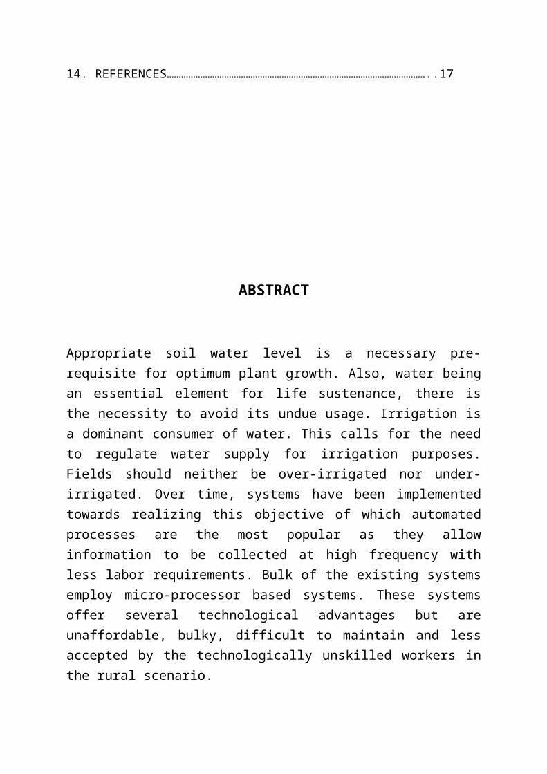
ABSTRACT
Appropriate soil water level is a necessary pre-requisite for optimum plant growth. Also, water being an essential element for life sustenance, there is the necessity to avoid its undue usage. Irrigation is a dominant consumer of water. This calls for the need to regulate water supply for irrigation purposes. Fields should neither be over-irrigated nor under-irrigated. Over time, systems have been implemented towards realizing this objective of which automated processes are the most popular as they allow information to be collected at high frequency with less labor requirements. Bulk of the existing systems employ micro-processor based systems. These systems offer several technological advantages but are unaffordable, bulky, difficult to maintain and less accepted by the technologically unskilled workers in the rural scenario.
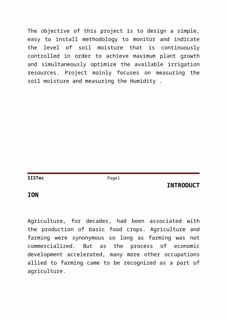
The objective of this project is to design a simple, easy to install methodology to monitor and indicate the level of soil moisture that is continuously controlled in order to achieve maximum plant growth and simultaneously optimize the available irrigation resources. Project mainly focuses on measuring the soil moisture and measuring the Humidity .
SISTec Page1
INTRODUCTION
Agriculture, for decades, had been associated with the production of basic food crops. Agriculture and farming were synonymous so long as farming was not commercialized. But as the process of economic development accelerated, many more other occupations allied to farming came to be recognized as a part of agriculture.
At present, agriculture besides farming includes forestry, fruit cultivation, dairy, poultry, mushroom, bee keeping, arbitrary, etc. Today, marketing, processing, distribution of agricultural products etc. are all accepted as a part of modern agriculture.
Thus, agriculture need the mass production for economy growth. So need fast production with balance parameter like water level humidity fertilizers level and other thing for the good quality of crops. Here present the concept of autonomous agriculture. In that the humidity of soil is measure by the sensor and it maintain as per crops requirement.
SISTec Page 2
HARD WARE EQUIPMENTS
• POWER SUPPLY BLOCK
• MICROCONTROLLER (ATMEGA8L)
• LCD
• HUMIDITY SENSOR
• BC547 TRANSISTOR
• RELAY
• 1N4007
• LED
• RESISTORS & CAPACITORS
SISTec Page 3
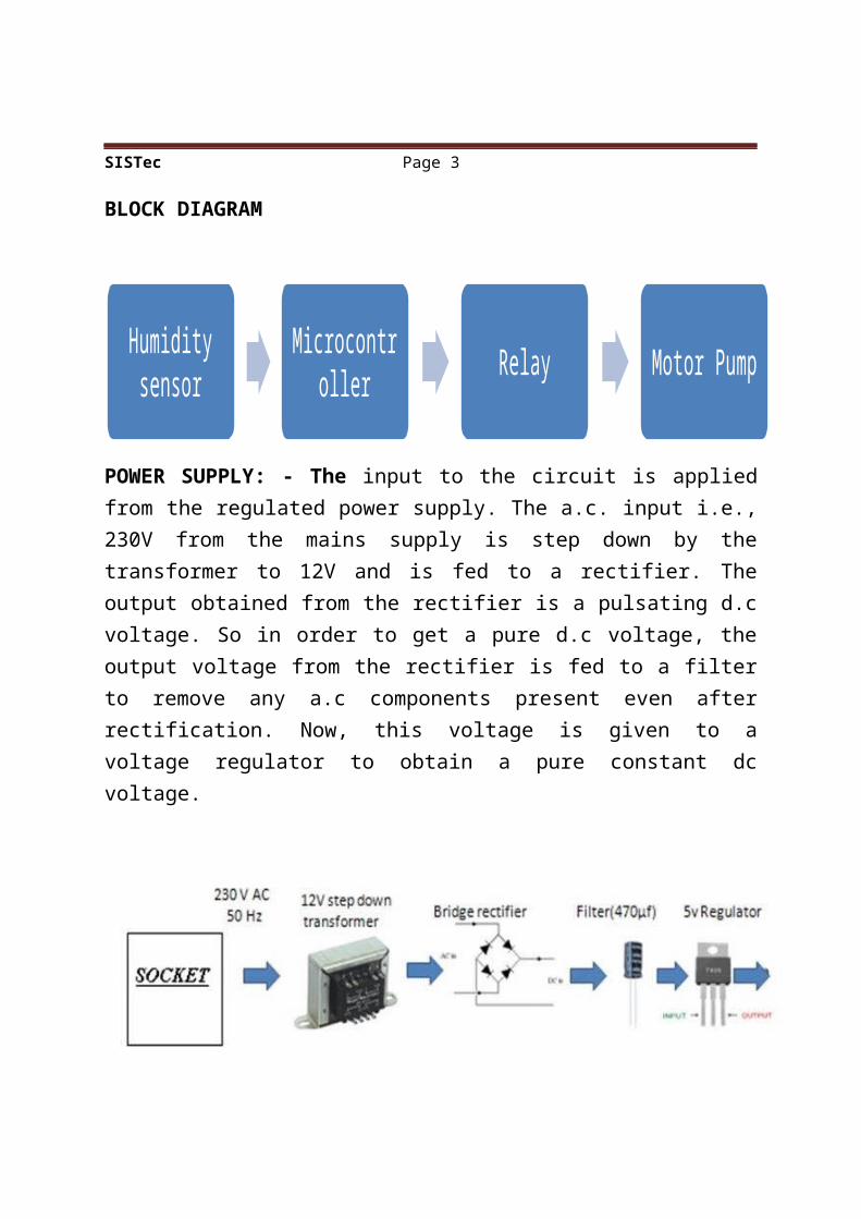
BLOCK DIAGRAM
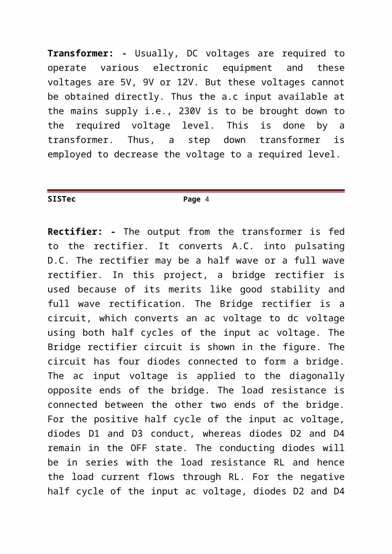
POWER SUPPLY: - The input to the circuit is applied from the regulated power supply. The a.c. input i.e., 230V from the mains supply is step down by the transformer to 12V and is fed to a rectifier. The output obtained from the rectifier is a pulsating d.c voltage. So in order to get a pure d.c voltage, the output voltage from the rectifier is fed to a filter to remove any a.c components present even after rectification. Now, this voltage is given to a voltage regulator to obtain a pure constant dc voltage.
Transformer: - Usually, DC voltages are required to operate various electronic equipment and these voltages are 5V, 9V or 12V. But these voltages cannot be obtained directly. Thus the a.c input available at the mains supply i.e., 230V is to be brought down to the required voltage level. This is done by a transformer. Thus, a step down transformer is employed to decrease the voltage to a required level.
Humidity sensor Microcontroller Relay Motor Pump
SISTec Page 4
Rectifier: - The output from the transformer is fed to the rectifier. It converts A.C. into pulsating D.C. The rectifier may be a half wave or a full wave rectifier. In this project, a bridge rectifier is used because of its merits like good stability and full wave rectification. The Bridge rectifier is a circuit, which converts an ac voltage to dc voltage using both half cycles of the input ac voltage. The Bridge rectifier circuit is shown in the figure. The circuit has four diodes connected to form a bridge. The ac input voltage is applied to the diagonally opposite ends of the bridge. The load resistance is connected between the other two ends of the bridge. For the positive half cycle of the input ac voltage, diodes D1 and D3 conduct, whereas diodes D2 and D4 remain in the OFF state. The conducting diodes will be in series with the load resistance RL and hence the load current flows through RL. For the negative half cycle of the input ac voltage, diodes D2 and D4 conduct whereas, D1 and D3 remain OFF. The conducting diodes D2 and D4 will be in series with the load resistance RL and hence the current flows through RL in the same direction as in the previous half cycle. Thus a bi-directional wave is converted into a unidirectional wave.
Filter: - Capacitive filter is used in this project. It removes the ripples from the output of rectifier and smoothens the D.C. Output received from this filter is constant until the mains voltage and load is maintained constant. However, if either of the two is varied, D.C. voltage received at this point changes. Therefore a regulator is applied at the output stage.
Voltage regulator: - As the name itself implies, it regulates the input applied to it. A voltage regulator is an electrical regulator designed to automatically maintain a constant voltage level. In this project, power supply of 5V and 12V are required. In order to obtain these voltage levels, 7805 and 7812 voltage regulators are to be used. The first number 78 represents positive supply and the numbers 05, 12 represent the required output voltage levels. The L78xx series of three-terminal positive regulators is available in TO-220, TO-220FP, TO-3, D2PAK and DPAK packages and several fixed output voltages, making it useful in a wide range of applications.
SISTec Page 5
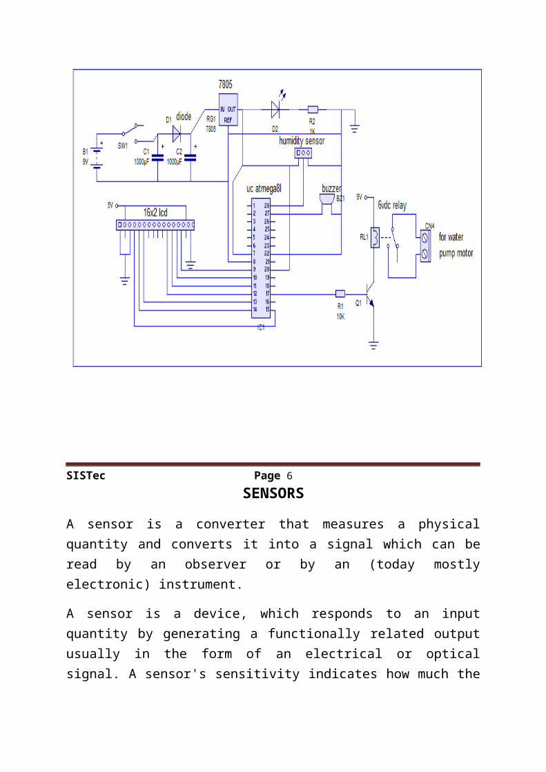
These regulators can provide local on-card regulation, eliminating the distribution problems associated with single point regulation. Each type employs internal current limiting, thermal shut-down and safe area protection, making it essentially indestructible. If adequate heat sinking is provided, they can deliver over 1 A output current. Although designed primarily as fixed voltage regulators, these devices can be used with external components to obtain adjustable voltage and currents.
CIRCUIT DIAGRAM
SISTec Page 6
SENSORS
A sensor is a converter that measures a physical quantity and converts it into a signal which can be read by an observer or by an (today mostly electronic) instrument.
A sensor is a device, which responds to an input quantity by generating a functionally related output usually in the form of an electrical or optical signal. A sensor's sensitivity indicates how much the sensor's output changes when the measured quantity changes.
Soil moisture sensor:
Working Principle
Soil moisture sensors measure the water content in soil. All plants need water to grow and survive. Soil moisture sensors used to determine how much water are needed to irrigate the plants.
Humidity and Temperature Sensor (DHT11)
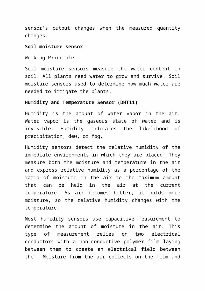
Humidity is the amount of water vapor in the air. Water vapor is the gaseous state of water and is invisible. Humidity indicates the likelihood of precipitation, dew, or fog.
Humidity sensors detect the relative humidity of the immediate environments in which they are placed. They measure both the moisture and temperature in the air and express relative humidity as a percentage of the ratio of moisture in the air to the maximum amount that can be held in the air at the current temperature. As air becomes hotter, it holds more moisture, so the relative humidity changes with the temperature.
Most humidity sensors use capacitive measurement to determine the amount of moisture in the air. This type of measurement relies on two electrical conductors with a non-conductive polymer film laying between them to create an electrical field between them. Moisture from the air collects on the film and causes changes in the voltage levels between the two plates. This change is then converted into a digital measurement of the air’s relative humidity after taking the air temperature into account.
SISTec Page 7
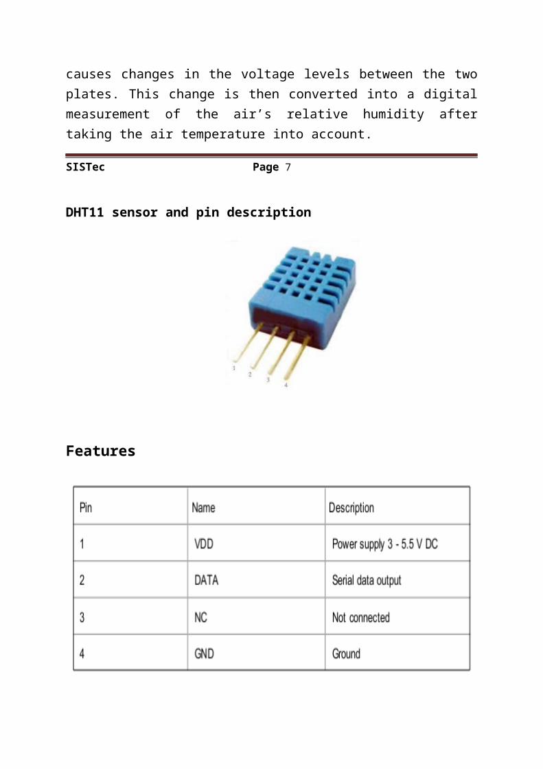
DHT11 sensor and pin description
Features
Low cost, long-term stability, relative humidity and temperature measurement, excellent quality, fast response, strong anti-interference ability, long distance signal transmission, digital signal output, and precise calibration.
SISTec Page 8
MICROCONTROLLER
A microcontroller (sometimes abbreviated µC, UC or MCU) is a small computer on a single integrated circuit containing a processor core, memory, and programmable input/output peripherals. Program memory in the form of NOR flash or OTP ROM is also often included on chip, as well as a typically small amount of RAM. Microcontrollers are designed for embedded applications, in contrast to the microprocessors used in personal computers or other general purpose applications.
Basic Peripherals in a Microcontroller:
1. I/O ports.
2. Interfacing with LCD
3. Analog to Digital Conversion (ADC)
4. USART
5. Timers/Counters
6. Interrupts
7. I2C
8. SPI
Uses of Microcontrollers:
Microcontrollers are used in automatically controlled products and devices, such as automobile engine control systems, implantable medical devices, remote controls, office machines, appliances, power tools, toys and other embedded systems. By reducing the size and cost compared to a design that uses a separate microprocessor, memory, and input/output devices, microcontrollers make it economical to digitally control even more devices and processes. Mixed signal microcontrollers are common, integrating analog components needed to control non-digital electronic systems.
SISTec Page 9
About AVR Atmega8l:
a) I/O and Packages: 23 Programmable I/O Lines, 28-lead PDIP
b) Operating Voltages: 2.7V - 5.5V (ATmega8L)
4.5V - 5.5V (ATmega8)
C) Power Consumption:
At 4 MHz, 3V, 25°C:
Active: 3.6mA
Idle Mode: 1.0mA
Power-down Mode: 0.5Μa
SISTec Page 10
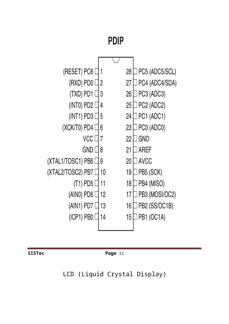
PIN DIAGRAM(ATMEGA8L)
SISTec Page 11
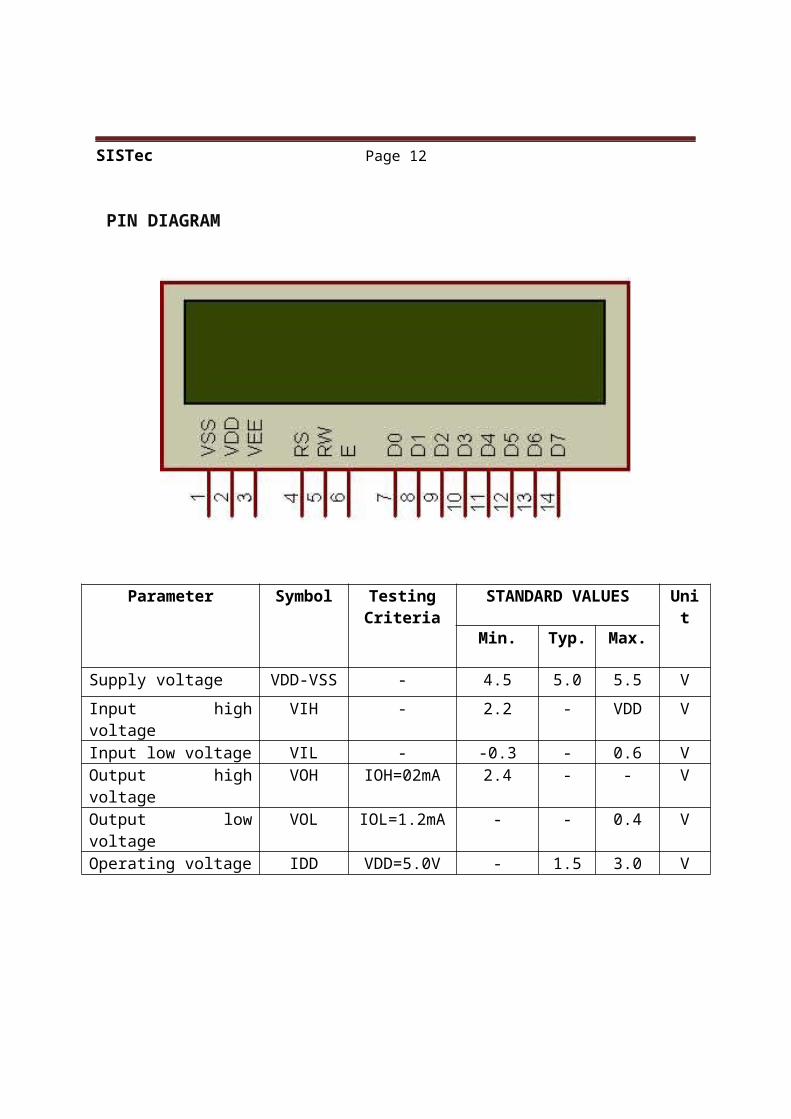
LCD (Liquid Crystal Display)
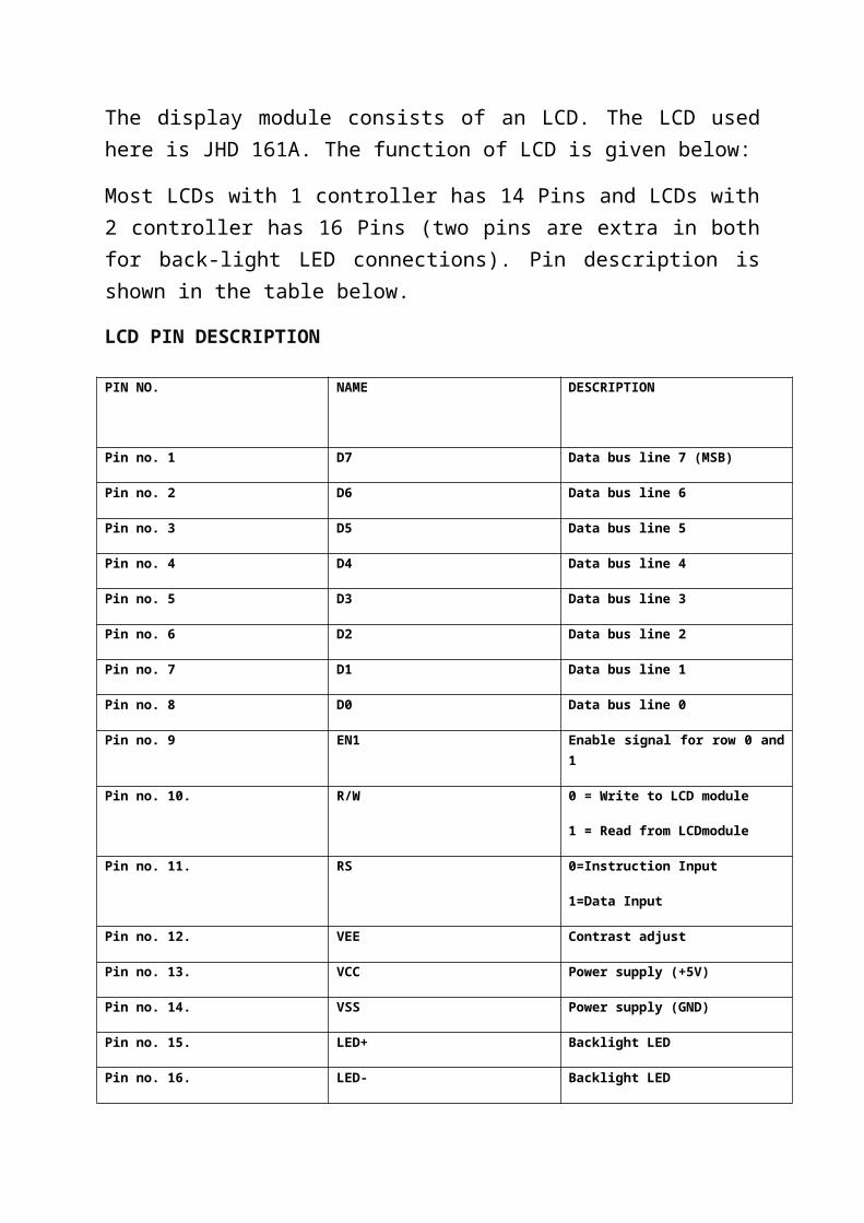
The display module consists of an LCD. The LCD used here is JHD 161A. The function of LCD is given below:
Most LCDs with 1 controller has 14 Pins and LCDs with 2 controller has 16 Pins (two pins are extra in both for back-light LED connections). Pin description is shown in the table below.
LCD PIN DESCRIPTION
PIN NO. NAME DESCRIPTION
Pin no. 1 D7 Data bus line 7 (MSB)
Pin no. 2 D6 Data bus line 6
Pin no. 3 D5 Data bus line 5
Pin no. 4 D4 Data bus line 4
Pin no. 5 D3 Data bus line 3
Pin no. 6 D2 Data bus line 2
Pin no. 7 D1 Data bus line 1
Pin no. 8 D0 Data bus line 0
Pin no. 9 EN1 Enable signal for row 0 and 1
Pin no. 10. R/W 0 = Write to LCD module
1 = Read from LCDmodule
Pin no. 11. RS 0=Instruction Input
1=Data Input
Pin no. 12. VEE Contrast adjust
Pin no. 13. VCC Power supply (+5V)
Pin no. 14. VSS Power supply (GND)
Pin no. 15. LED+ Backlight LED
Pin no. 16. LED- Backlight LED
SISTec Page 12
PIN DIAGRAM
Parameter Symbol TestingCriteria
STANDARD VALUES Unit
Min. Typ. Max.
Supply voltage VDD-VSS - 4.5 5.0 5.5 V
Input high voltage VIH - 2.2 - VDD VInput low voltage VIL - -0.3 - 0.6 VOutput high voltage VOH IOH=02mA 2.4 - - VOutput low voltage VOL IOL=1.2mA - - 0.4 VOperating voltage IDD VDD=5.0V - 1.5 3.0 V
SISTec Page 13
RELAY
A relay is an electrically controllable switch widely used in industrial controls, automobiles and appliances. The relay allows the isolation of two separate sections of a system with two different voltage sources i.e., a small amount of voltage/current on one side can handle a large amount of voltage/current on the other side but there is no chance that these two voltages mix up.
Fig: Circuit symbol of a relay Operation-
when current flows through the coil, a magnetic field are created around the coil i.e., the coil is energized. This causes the armature to be attracted to the coil. The armature’s contact acts like a switch and closes or opens the circuit. When the coil is not energized, a spring pulls the armature to its normal state of open or closed. There are all types of relays for all kinds of applications.
Fig: Relay Operation and use of protection diodes
Transistors and ICs must be protected from the brief high voltage 'spike' produced when the relay coil is switched off.
SISTec Page 14
The above diagram shows how a signal diode (eg 1N4148) is connected across the relay coil to provide this protection. The diode is connected 'backwards' so that it will normally not conduct. Conduction occurs only when the relay coil is switched off, at this moment the current tries to flow continuously through the coil and it is safely diverted through the diode. Without the diode no current could flow and the coil would produce a damaging
high voltage 'spike' in its attempt to keep the current flowing.In choosing a relay, the following characteristics need to be considered:
1. The contacts can be normally open (NO) or normally closed (NC). In the NC type, the contacts are closed when the coil is not energized. In the NO type, the contacts are closed when the coil is energized.
2. There can be one or more contacts. i.e., a different type like SPST (single pole single throw), SPDT (single pole double throw) and DPDT (double pole double throw) relays.
3. The voltage and current required to energize the coil. The voltage can vary from a few volts to 50 volts, while the current can be from a few milliamps to 20milliamps. The relay has a minimum voltage, below which the coil will not be energized. This minimum voltage is called the “pull-in” voltage.
4. The minimum DC/AC voltage and current that can be handled by the contacts. This is in the range of a few volts to hundreds of volts, while the current can be from a few amps to 40A or more, depending on the relay.
TRANSISTOR: - A transistor is a semiconductor device used to amplify and switch electronic signals. It is made of a solid piece of semiconductor material, with at least three terminals for connection to an external circuit. A voltage or current applied to one pair of the transistor's terminals changes the current flowing through another pair of terminals. Because the controlled (output) power can be much more than the controlling (input) power, the transistor provides amplification of a signal. Some transistors are packaged individually but many more are found embedded in integrated circuits.
SISTec Page 15BUZZER: - A buzzer or beeper is an audio signaling device, which may be mechanical, electromechanical, or electronic. Typical uses of buzzers and beepers include alarms, timers and confirmation of user input such as a mouse click or keystroke.
FEASIBILITY: - The Sensor sense the humidity and give the Analog signal to Pin no. 28 of microcontroller, the set of instruction in the microcontroller calculate the humidity in the soil which mean the water level present in the soil. Than as per crops requirement microcontroller start and stop water pump of farms.
ADVANTAGES
Consumes time-it the system is installed once then we can set a timer to water for specific time interval.
By using this type irrigation systems the position of the water is effectively targeted where there is a need.
High frequency due to water distribution.
DISADVANTAGES
Design of the system is expensive High amount of energy is required Loss of water due to evaporation
FUTURE SCOPE:
This concept can be improved in future by enhancing it by integrating with GSM technology, such that whenever the water pump switches ON/OFF, an SMS is delivered to the concerned person regarding the status of the pump.
SISTec Page 16
CONCLUSION:-
The project “automatic irrigation system on sensing soil moisture content” has been successfully studied. The project is developed to sense the moisture content present in the soil. We can detect if the soil is dry or wet with motor operation. The advantage of this project to decrease the human involvement and still make certain appropriate irrigation systems with high efficiency.
REFERENCES:
www.efymag.com
www.elec circuit.com
SISTec Page 17