soil failure and force prediction for soil engaging discs
TRANSCRIPT

1 Oh SOIL U S E A N D MANAGEMENT Volume 3. Number 3 . Sentember 1YX7
Soil failure and force prediction for soil engaging discs
R.J. Godwin,' D.A. Seig2 & M. Allott3
Abstract. The soil forces acting upon agricultural discs arise from both a passive reaction on the concave hce and scrubbing reaction on the convex face. The magnitude of these reactions is a function of both the disc geometry, primarily the radius of the sphere from which the disc is formed, and the angle of the disc to the direction of travel. These forces can be predicted within acceptable limits using soil mechanics theories based upon Mohr-Coulomb properties. From both the theoretical and practical results optimum disc setting can he selected to give low specific resistance values. The prediction model has been successfully used with stress analysis techniques to design new disc geometries and, with the advent of improved materials, to select appropriate disc thicknesses.
INTRODUCTION DISC GEOMETRY
7 OIL engaging discs (Fig. 1) are widely incorporated in L 5 a range of agricultural machines from those used for
primary soil loosening to producing ridges. T h e main applications are either in the form of disc ploughs for primary tillage or disc harrows for creating tilth and clod disintegration. 'The face of the disc is vertical in the case of the disc harrow, whilst to gain additional penetration the face o f the disc plough is inclined rearwards.
A number of empirical studies have been conducted on the effect of disc geometry on soil failure and the resulting soil forces, e.g. those of Gill et ul. (1978) and Harrison ( 1 077). However, no proven models of soil mechanics exist to explain the behaviour of the disc and relate the resulting forces to the properties of the soil. Prediction models based upon Mohr-Couloumb theories of soil mechanics have bt:en developed for other tillage implements by Payne ( 1 9Sh), O'Callaghan & Farrelly (1964), Hettiaratchi et ul. ( 1 966), Hettiaratchi & Reece (1967) and Godwin & Spoor ( 1 077) and are useful to the tillage engineer and designer in understanding soil failure and predicting the forces involved. These models are potentially powerful when used in conjunction with stress analysis to predict the resulting stress distribution on the implement, from which the size and material specification of components can be designed. This allows the effect of proposed changes in the geometry of implements and specifications of new material to be investigated without the need to produce a range of costly physical prototypes.
' I:kp;irtnient of Engineering tbr Agriculture, Silsoe College, Cranfield lnititute of'l'cchnolop, Silsoe, Redford MK45 4LYI'.
4gricultural Engineering Ikpament , ' lhe University, Newcastle upon ' I 'yc , Newcastle NEI 7 K U . 'l\t'.:\. 'l'vsack plc, Horseman \Vorks, Alma Street, ShetXeld 53 8ST.
Traditional discs are manufactured in the form of sections of spherical surfaces. T h e principal feature is the radius of the sphere for a given rim diameter. The smaller the spherical radius the greater is the concavity of ithe disc and the smaller the rake angle (a), see Fig. A l . This paper reports studies on two spherical discs of different con- cavities and a third disc in the form of a truncated cone. Table 1 gives the principal features. .411 the discs had identical rim diameters, with an external bevel which influenced the magnitude ofthe clearance angle (A), i.e. the angle between the plane of the disc face and the disc edge, see Fig. 2.
T h e effect of a given disc shape is further affected by both the angle of attachment of the disc to the direction of travel, sweep angle (O), see Fig. 2, and the angle of the disc face to the vertical. As the main objective ofthis work was to investigate applications to disc harrows, the disc face was maintained in the vertical plane.
SOIL FAILURE AND FORCE SYSTEMS
Laboratory studies of the three disc geometries in control- led sandy loam soil conditions show that the complex, three-dimensional reaction of the soil failure caused by discs can be separated into two-componcnt reactions. 'I'he magnitude of each component is a function of' the \weep angle (0) of the disc, as shown diagramatically in Fig. 2.
With the sweep angle equal to 90", Figs 2(a) and 3 , the soil is simply bulldozed ahead of the disc, moving both forwards and upwards. As a result the soil is generally loosened through a form of passive soil failure. As the sweep angle is reduced from 90" (see Fig. 3 ) the size ofthe boundary remains almost constant whilst the onentation of the edge of the passive loosening changes.

SOIL USE A N D MAYAGEMENT kolume 3, Number 3, September 1987 107
Fig.1. Soil-disc interaction. (a) Passive reaction on concave face. (b) Scruhbing reaction on convex face.
When the sweep angle is reduced so that i t is marginall! less than the clearance angle (A) of the disc a scrubbing reaction occurs on the convex face ofthe disc (Figs 1 (b) and 2(b)). Further reductions in the sweep angle reduce the magnitude of the passive reaction and increase the scrub- bing reaction until at zero sweep angle all the soil reaction ofthe scrubbing form, Fig. 2(c) . As a result ofthe scrubbing reaction the soil is forced forwards, sideways and down- wards and is generally compacted.
Both the passive and scrubbing reactions produce verti- cal and horizontal forces on the disc. The scrubbing reaction always produces an upward vertical force, whilst the direction of the vertical force from the passive reaction
Table 1 . Disc geometries for two depths olwork (4
depends on the rake angle ( a ) ofthe disc. With rake angles greater than 90O-6 (where 6 is the angle of friction between the soil and the disc face) this force is upwards, while discs with lesser rake angles produce a downward force. T h e horizontal reactions normal to the disc contact edges are shown in Fig. 4. Resolving these components in line with and normal to the direction of travel indicates the addictive effect of the former, while the latter are in opposition.
T h e summations of these force components arc given below:
L'r = I$ + I/: (+ve forces oppose penetration),
DT = D,, +D, (+ve forces oppose
S, = S, -S, (+ve forces act from
(1)
direction of travel), (2)
concave to convex faces), ( 3 )
where L$. DT and ST are the total vertical, draught and side forces arising from the passive (suffk,p) and scrubbing (suffix, s) components. The equations for the calculation of each are presented in the Appendix. These are based upon the principles of Mohr-Coulomb soil mechanics and application of two theories. The first, the two-dimensional cutting theory developed by Hettiaratchi rt al. (1966), Hettiaratchi & Reece (1974) is used for estimating the passive component. The scrubbing component is compres- sive in nature and is estimated using the bearing capacity theory developed for angled footings by Meyerhof (1961).
T h e predicted values of the passive and scrubbing com- ponents and the resultant force totals for the conical disc working 0.1 m deep over a range of sweep angles from 0" to 90" are given in Fig. 5. These relationships show the following:
(1) 'The magnitudes of the draught and vertical passive force components decrease with reduction in sweep angle whilst the lateral force increases to a maximum at a sweep angle of 45" and then decreases.
(2) T h e mapitudcs of the draught, vertical and lateral scrubbing force components decrease from their respective maxima a t a sweep angle ofO" to zero at a sweep angle equal to the clearance angle ( A ) of the disc.
(3) The addition of passive and scrubbing components produce the total force.
lffcctive rakc Kim angle (a )
radius (see Fig. (:learance angle (A) N (see Fig. .A3)
Disc Qpe (W 11) 1/ = 0.04ni I).IOm it = 0.04m 0.10m
Shallow spherical 0.305 ni 60" 20" 30" 0 037 in 0.075 m Deep spherical 0.305 m 65" 35" 4.5" 0.025 m 0.043 m Conical 0.305 m 61" 25" 35. 1).034 m 0.050 m

1 (1X S O I L USE A N D MANAGEMEN'I' Volume 3, Number3, September 19x7 -
SWEEP
8 < A
t
< CLEARANCE ANGLE
a.
8 = 9 0 I I
ALL SIMPLE
PASSIVE
t b. I
I 4 I
I
C. INITIATION
OF SCWBING
A 'rf I ALL SCRUBB'WG
I e = o <
w I( in RANGE 0 = 0 + A then both reactions occur
Fig. 2. Plan view ofdisc showing: (a) 90" sweep mgle; (b) initiation of scrubbing reaction at 8 < A; (c) scrubbing reaction at 8 = 0.
COMPARISON BETWEEN EXPERIMENTAL AND PREDICTED
DISC FORCES
Ch-nparison between the results of the force measure- ments conducted for the three disc geometries (Table 1) at
90' a Direction of Travel
65' 0 4 5 O
26'
17'
0 d 0
e
1;ig. 3. 1 f k c . t ot'disc sweep angle o n the plan area ofcrescent boundaries.
two working depths in a sandy loam soil (Table 2) and those from the force prediction model are given in Fig. 6. In general the predicted forces reflect the changes in magni- tude of the force components. In particular both predic- tions and experimental data indicate:
(1) The minimum value of the draught force occurs in the range 20-30" for the 3 discs studied. Tht: minimum value of the draught force occurs at sweep angles less than the clearance angle (A) .
(2) The rapid increase in vertical torce ;IS the sweep angle decreases below the clearance angle (A) .
(3) There is a reversal in the direction ofthe l;iteral forcc with sweep angles in the region of 10-25". ?'hiis occurs at sweep angles less than the clearance angle (A) and hence there must be some scrubbing to balance the passive component. (4) The working depth affects the magnihJde of the
forces.
Overall, the expenmental data confirm the predicted differences between the shallow and deep spherical discs, with the shallow spherical disc having smaller draught and vertical forces at smaller sweep angles together with a smaller sweep angle for the equilibrium position of the lateral forces.
Comparison of the predicted forces with the results of Gill et ul. (1978) in a silty clay loam soil using the soil properties derived by Williford (1 967) (l'able 2,) are given in Fig. 7. These also show reasonable agrecment. 'The major discrepancy between the predicted ,and expenmental

SOIL USE A N D MANAGEMENT Volume 3, Number 3, September 1987 109
A = Clearance angle DIRECTION
OF TRAVEL SCRUBBING 8 = Sweep angle
PASSIVE SOIL CRESCENT
GEN. SOIL MECH. EOU
REACTION
BEARING CAPACITY THEORY
lig. 4. Horimntal force components xising trim p a s i w and scrubbing reactions.
results in both the sandy loam and clay loam soils is in the direction of the vertical force. The experimental vertical forces are directed upwards at sweep angles in excess of the clearance angle (A) whilst the predicted force is directed downwards. This discrepancy is explained by the effect of the edge geometry, which is not perfectly sharp as assumed in the model and shown in Fig. 8(a) but has of necessity a slight backward raked edge (Fig. 8(b)) which produces an upward vertical force.
- Y A D p
DRAUGHT , ;;.....,/ ./'"''
FORCE (kN) . . . D s
0 . '
VERTICAL 1 '\Vt FORCE
LATERAL 1;; ' ,) "\. FORCE (kN) t/
90 0 30 60
Sweep Angle (8 O)
Fig. 5. Predicted forces \howing passive and scrubbing reactions for the conical disc working 0.1 rn deep.
SPECIFIC RESISTANCE
Although sweep angles in the range of 20" to 30" give the minimum draught force, this is of little practical value if the amount of soil disturbance is disproportionately small. A more realistic property from which to judge tillage effi- ciency is specific resistance, i.e. draught force per unit area of soil disturbed. Experimental and predicted specific resistance data are given in Fig. 9 for the conical disc over the full range of sweep angles. Fig. 9 shows the effect of operating discs at small sweep angles where the combi- nation of large draught forces and small soil disturbances produces large specific resistances. The point of minimum specific resistance occurs at approximately 25". At sweep angles greater than 25" the specific resistance increases as the draught force increases at a marginally greater rate than the disturbed area.
Considering the vertical and lateral forces acting upon the disc, the sweep angle for minimum specific resistance is close to the optimum for these forces with the vertical force almost a minimum and the lateral force close to the equili- brium position.

1 1 0 SOlL USE A N D MANAGEMENT Volume 3, Number 3, September 1987
.--- LATERAL - O " " . ' 2 0 40 6 0 2 0 0 20 4 0 6 0
DRAUGHT FORCE
(1")
VERTICAL FORCE (kN)
Table 2. Soil properties
Sandy loam Silty clay loam
Bulk Unit Weight-initial
Cohesion Adhesion Angle of internal shearing resistance Angle ofsoil-metal friction Particle size distribution ( p n )
final
2000-20 20-2
< 2
7, = 12.77kNmP' 13.75 kN m-," yr = 11.77kNm 11.771dVm-:' c = 10.20 kN m-r 37.90 kN nir2 ca = O.OOkNmmY 0 . 0 0 k N m P (jJ = 38" 29" 6 = 22" 26"
DEPTH =0.10m
- I Conical
Deep Spherical
Spherical
- - -
Shal low - - - _ _
\
DEPTH 0.04m
0 - . C o n i c a l _ _ - o D e e p
S p h e r i c a l
S p h e r i c a l S h a l l o w
'i-.. 0 0
LATERAL FORCE
(kN)
-1
LATERAL FORCE (kN)
S w e e p Angle ( 8 O )
0 30 6 0 90
S w e e p A n g l e ( 8 1
Fig. 6. Comparison of predicted and experimental fbrces (symbol) filr three disc geometries at 0.1 rn and 0.04 m depth in a sandy loam soil.
S w e e p Angle ( 8 )
Fig. 7. Comparison of predicted and experimental forces (from Gill ef ul. 1978) in a silty clay loam soil.

SOIL USE AND MANAGEMENT Volume 3, Number 3, September 1987 111
Fig. 8. Disc edge geometry. (a) Ideal, perfectly sharp. (b) Practical, after manufacture and use.
Predicted \ Experimental SPECIFIC
RESISTANCE
4 1 \ S w e e p Angle ( 8 O)
Fig. 9. Predicted and experimental specific resistance
PRACTICAL APPLICATIONS The results of this investigation clearly identif) the point of minimum specific resistance and indicate that setting a disc outside this position would seriously affect its performance. Knowing this enables the disc to be adjusted as necessary, both during manufacture and when using the implement in the field.
Discs formed from spheres with small radii of curvature, i.e. those with deep concavities, have large clearance angles and hence require larger sweep angles to attain the opti- mum position.
The prediction model has been adopted by the sponsors to investigate various disc designs thus reducing the number of prototypes requiring both manufacture and field testing. A good example is the advent of improved steels, such as Earth Alloy which is approximately 20% stronger than the traditional disc material. The predicted forces for a range of soil conditions can be used when performing a stress analysis on the proposed disc shape. The stress distribution generated using finite element analysis on a proposed disc shape is shown in Fig. 10, where the zone of greater stress occurs at the lower edge of the central locating hole.
These techniques reduce the time and cost required to introduce improved products to the market. One example is a new disc constructed from Earth Alloy with an ellipsoi- dal cross-section. In this the load is carried by a smaller section of material with a more even stress distribution. At the same time it can penetrate as well as the earlier designs even though the discs weigh 20% less than conventional
ones. Independent field testing by AFRC Engineering (formerly National Institute of Agricultural Engineering) has confirmed that the ellipsoidal discs performed as predicted.
The disc prediction model, together with finite element analysis, is being used by the sponsors to design and select discs to meet their customers' needs specifically in both the United Kingdom and North America.
WORKING DEPTH - 155 m LOADPRESSURE- l l O K P a
EN42 MAR. 4.5 mn
Fig. 10. Stress distribution from finite element analysis.
CONCLUSIONS
Two forms of soil failure affect the magnitude and direc- tion of the forces acting on agricultural discs. These consist of a passive reaction on the concave face and a scrubbing reaction on the convex face. The magnitude of each is dictated by the sweep angle (0) and the clearance angle (A) of the disc. At angles of 8 larger than A the scrubbing action has no effect. Minimum draught forces and specific resist- ance values occur at sweep angles less than the clearance angles ( A ) . This position corresponds reasonably well to the point of minimum upward vertical force and the point of approximate balance between the opposing lateral passive and scrubbing reactions.
A soil mechanics model based upon Mohr-Coulomb properties adequately reflects the changes in the soil forces due to changes in working depth, sweep angle and disc curvature. The model has been proven to be a satisfactory technique for the design and selection of new disc designs when used with stress analysis techniques.
1 12. SOIL USE A N D MANAGEMEN -
A C K N O W L E D G E M E N T S
The authors express their gratitude to W.A. Tyzack plc for both sponsoring the study and allowing the results to be published, Dr. W.R. Gill and his colleagues at the National Soil Dynamics Laboratory (formerly National Tillage Machine Laboratory), Alabama, USA, for providing addi- tional data, and AFRC Engineering for evaluating the ellip- soidal disc.
R E F E R E N C E S (iill, W . K . , Keaves, <I. & Bailey, A. 1978. Effect ofgeometric parameters
on disk forces. Puper 78-1.53.5, American Society of Agricultural Engineers, St. Joseph, Michigan, USA.
Godwin, R.J. & Spoor, G. 1977. Soil failure with narrow tines..youmulcfl :lpicuIiitrul Engineering Reseurch 22,213-228.
I larrison, H.P. 1977. Soil Reacting forces for disks from field measure- ments. Trunsui-tiuns ASAE 20,836-838.
Hettiaratchi, D.R.P.. Witney, D.B. & Reece, A.R. 1966. The calculation of' passive pressure in two dimensional soil failure. ~i'ournulof.4p'- idturul EngineerinxResearch 11,89- 107.
Hcttiaratrhi, D.R.P. & Reece, A.R. 1974. T h e calculation ofpassive soil resistance. Giott~hniquc 24,289 -310.
Xle:verhof, G.G. 3961. The ultimate bearing capacity of wedge shaped foundations. Proceedings Sih Intemutionul Confeenci, on Soil Mechanics u r r d Founduiion Engineen'ngVol 11 Division 313, DUNOD, Paris.
O'(:allaghan, J.R. & Farrelly, K.M. 1964. Cleavage of soil by tined implements.~~~iurnul if lA~'i~1turalEn~neen~ngResearch 9,259-270.
I'iiyne, P.C.J. 1956. The relationship between the mechanical properties of soil and the performance ofsimple cultivation implements.~o'ournul c! /Api id iurul Engineering Reseurch 1,23 -50.
Willitord, J.R. 1967. .In inz>esiigution cf soil strength ~ l i r e s included in m e inrlt,.x reudings. Unpublished MS Thesis, Ralph B, Draughton I ihrary, Auhurn Universitv, Auburn, Alabama, USA.
A P P E N D I X : D E R I V A T I O N OF P R E D I C T I O N E Q U A T I O N S F O R SOIL
D I S C F O R C E S
Ash id nzptions Following the observed pattern of soil failure the following assumptions were made:
(1)The concave or facial reaction acts normal to the chord of the disc at the soil surface. (Little soil lateral movement was observed at the face of the disc.)
(2) The concave or facial reaction has a maximum value when the sweep angle (8) = 90" and reduced to zero when 0 == 0". A sinusoidal relationship was assumed between the two extremes and incorporated as an effective width term. 'This was justified since changes in sweep angle at angles approaching 90" has little effect but changes become more significant at smaller values of 8.
(3) The magnitude of the surcharge reaction has a maxi- mum value when the sweep angle 8 = 90" and reduces to zero when 8 = 0". At 90" soil accumulates to a height equal to that of the disc axle, at low sweep angles no soil accumu- lation occurs.
i(4) The scrubbing reaction on the rear of the disc has a
T Volume 3, Number 3, September 1987
maximum value when the sweep angle (0) i s 0" and reduces to zero, through a sinusoidal relationship, as the sweep angle increases to the disc clearance angle (A). At sweep angles greater than A there is no scrubbing.
I Concuve or fucial readon Determinution of the passive reaction (P). Prediction of the
forces acting upon this section of the disc is based upon the passive soil cutting solution developed by Hettiaratchi et d. (1 966) for simple blades:
(1) P = (y,d2Ny +cd&,, +yd4Jl ,
where
P = passive cutting reaction d = depth of disc (assumed constant) y = soil bulk unit weight (i: initia1,J final) c = cohesion y = surcharge stress, which is a function of sweep angle
(2)
dimensionless numbers, from Hettiaratchi etal. (1960)
from Assumption ( 3 )
4 = (R-d)y, sin 0
Y q and Hettiaratchi & Reece (1 974)
1 = effective width = Wsin 0 from assumption (2) where Wis true width at the depth ofthe disc ( r i ) and is gicen
W = 2 d 2 R d - d 2
%
by
where R is the radius of the disc rim, hencc
I = 2d2Rd-d2 sin 0. ( 3 ) Combining equations (l), (2) and (3) gives:
P = (y id2NY+cdN,,+(R-d)y/ .s in0d~,)
2dZRd-d'sin 8. (4) Partitioning (P) into three force componints. In line with
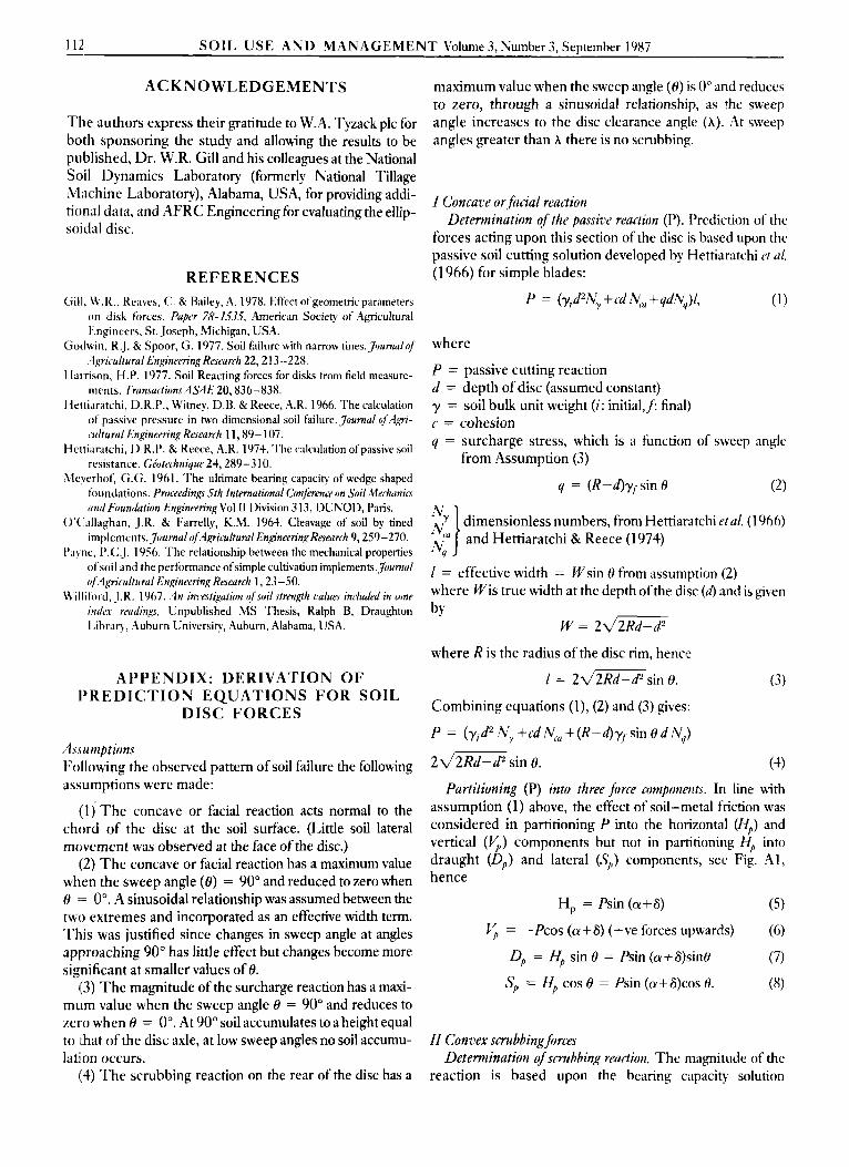
assumption (1) above, the effect of soil-metal friction was considered in partitioning P into the horizontal (H,,) and vertical (5) components but not in partitioning Hp into draught (D,,) and lateral (S,,) components, set Fig. A l , hence
H, = Psin (@+a) ( 5 ) Vp = -Pcos (a+6) (fve forces upwards) (6)
op = Hp sin 8 = Psin (a+6)sinO
Sp = Hp cos 0 = Psin (a+6)cos H. (7)
(8)
II Convex scrubbing forces Determination of scrubbing readon, The magnitude of the
reaction is based upon the bearing capacity solution
SOIL U S E A N D M A N A G E M E N T bolume 3. Number 3. SeDtember 1987 113
/ a. Elevat ion
Fig. A. I . Position and direction of passive soil reactions
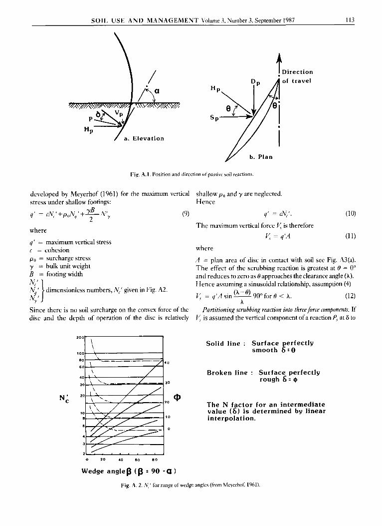
developed by Meyerhof (1961) for the maximum vertical stress under shallow footings:
4' = c y . ' +poNq +% N', 2
where
4' = maximum vertical stress c = cohesion po = surcharge stress y = bulk unit weight B = footingwidth
dimensionless numbers, w.' given in Fig. A2.
(9)
1 Direct ion of travel
shallow po and y are neglected. Hence
4' = cN,'. (10)
y = q'A (1 1)
The maximum vertical force y is therefore
where
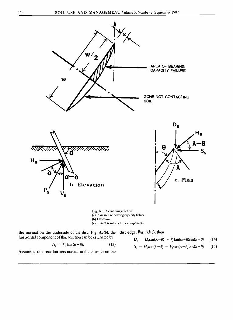
A = plan area of disc in contact with soil see Fig. A3(a). The effect of the scrubbing reaction is greatest at 8 = 0" and reduces to zero as 8 approaches the clearance angle (A). Hence assuming a sinusoidal relationship, assumption (4)
= 4'A sin- 900 for 0 < A. (12) A
Since there is no soil surcharge on the convex force of the disc and the depth of operation of the disc is relatively
Partitioning scrubbing reaction into three force components. If is assumed the vertical component of a reaction P, at 6 to
N d 20
2 0
10 10
6 0
4
3
2
0 20 40 60 8 0
Wedge a n g l e p (p : 90 - a
Solid line : Surface perfectly smooth 6 - 0
Broken line : Surface perfectly rough 6 = @
The N factor f o r an intermediate value ( 6 ) is determined by linear interpolation.
Q
Fig. A. 2. ,y ' for range of wedge angles (from hleyerhof, 1961).
114 SOIL USE AND MANAGEMENT Volume 3, Number 3, September 1987
AREA OF BEARING CAPACITY FAILURE
ZONE NOT CONTACTING
/ I b. Elevation D
cs vs
Fig. A. 3. Scrubbing reaction. (a) Plan area of bearing capacity failure. (b) Elevation. (c) Plan of resulting force components.
the normal on the underside of the disc, Fig. A3(b), the disc edge, Fig. A3(c), then horizontal component of this reaction can be estimated by
H, = V, tan (a+G).
Assuming this reaction acts normal to the chamfer on the
D, = Hssin(A-8) = Ktan(a+G)sin(h--O) (14)
(13) S, = Hscos(A-8) = 4tan(a-G)cos(h-O) (15)