software-testing-framework 3
DESCRIPTION
TRANSCRIPT
Software Testing Framework
Document version: 2.0
Harinath V Pudipeddi [email protected]
http://www.sqae.com
Software Testing Framework V2.0 2 of 25
Table of Contents
Table of Contents ...........................................................................................2 Revision History .............................................................................................4 Testing Framework .........................................................................................5
1.0 INTRODUCTION ........................................................................................................................... 5
1.2 TRADITIONAL TESTING CYCLE ...........................................................................5
2.0 VERIFICATION AND VALIDATION TESTING STRATEGIES................................... 6
2.1 VERIFICATION STRATEGIES ..............................................................................6 2.1.1 REVIEW’S ......................................................................................7 2.1.2 INSPECTIONS..................................................................................8 2.1.3 WALKTHROUGHS..............................................................................8
2.2 VALIDATION STRATEGIES ................................................................................8
3.0 TESTING TYPES ............................................................................................................................ 9
3.1 WHITE BOX TESTING .....................................................................................9 WHITE BOX TESTING TYPES................................................................................. 10
3.1.1 BASIS PATH TESTING ...................................................................... 10 3.1.2 FLOW GRAPH NOTATION................................................................... 10 3.1.3 CYCLOMATIC COMPLEXITY ................................................................. 10 3.1.4 GRAPH MATRICES .......................................................................... 10 3.1.5 CONTROL STRUCTURE TESTING........................................................... 10
3.1.5.1 Condition Testing........................................................... 10 3.1.5.2 Data Flow Testing .......................................................... 10
3.1.6 LOOP TESTING ........................................................................................ 11 3.1.6.1 Simple Loops .......................................................................... 11 3.1.6.2 Nested Loops .......................................................................... 11 3.1.6.3 Concatenated Loops................................................................. 11 3.1.6.4 Unstructured Loops.................................................................. 11
3.2 BLACK BOX TESTING ................................................................................... 11 BLACK BOX TESTING TYPES ................................................................................. 11
3.2.1 GRAPH BASED TESTING METHODS ....................................................... 11 3.2.2 EQUIVALENCE PARTITIONING.............................................................. 11 3.2.3 BOUNDARY VALUE ANALYSIS .............................................................. 12 3.2.4 COMPARISON TESTING..................................................................... 12 3.2.5 ORTHOGONAL ARRAY TESTING............................................................ 12 3.3 SCENARIO BASED TESTING (SBT).......................................................... 12 3.4 EXPLORATORY TESTING....................................................................... 13
4.0 STRUCTURAL SYSTEM TESTING TECHNIQUES ........................................................ 13 5.0 FUNCTIONAL SYSTEM TESTING TECHNIQUES......................................................... 13
4.0 TESTING PHASES ...................................................................................................................... 14
4.2 UNIT TESTING ........................................................................................... 15 4.3 INTEGRATION TESTING ................................................................................. 15
4.3.1 TOP-DOWN I NTEGRATION.................................................................. 15
Software Testing Framework V2.0 3 of 25
4.3.2 BOTTOM-UP I NTEGRATION................................................................. 15 4.4 SMOKE TESTING......................................................................................... 16 4.5 SYSTEM TESTING........................................................................................ 16
4.5.1. RECOVERY TESTING ....................................................................... 16 4.5.2. SECURITY TESTING........................................................................ 16 4.5.3. STRESS TESTING .......................................................................... 16 4.5.4. PERFORMANCE TESTING .................................................................. 16 4.5.5. REGRESSION TESTING .................................................................... 17
4.6 ALPHA TESTING ......................................................................................... 17 4.7 USER ACCEPTANCE TESTING........................................................................... 17 4.8 BETA TESTING........................................................................................... 17
5.0 METRICS ......................................................................................................................................... 17
6.0 TEST MODELS .............................................................................................................................. 19
6.1 THE ‘V’ MODEL.......................................................................................... 19 6.2 THE ‘W’ MODEL ......................................................................................... 20 6.3 THE BUTTERFLY MODEL ................................................................................ 21
7.0 DEFECT TRACKING PROCESS.............................................................................................. 23
8.0 TEST PROCESS FOR A PROJECT ........................................................................................ 24
9.0 DELIVERABLES ........................................................................................................................... 25
Software Testing Framework V2.0 4 of 25
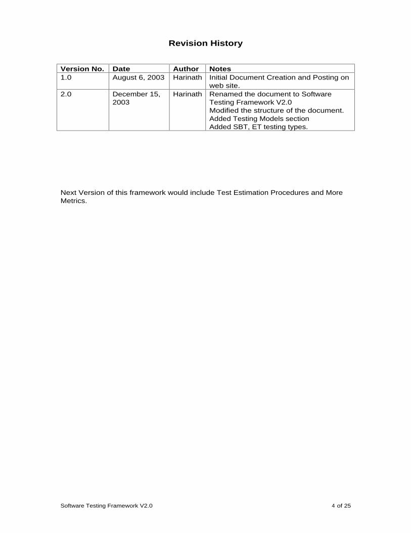
Revision History
Version No.
Date Author Notes
1.0 August 6, 2003 Harinath
Initial Document Creation and Posting on web site.
2.0 December 15, 2003
Harinath
Renamed the document to Software Testing Framework V2.0 Modified the structure of the document. Added Testing Models section Added SBT, ET testing types.
Next Version of this framework would include Test Estimation Procedures and More Metrics.
Software Testing Framework V2.0 5 of 25
Testing Framework
Through experience they determ ined, that there should be 30 defects per 1000 lines of code. I f test ing does not uncover 30 defects, a logical solut ion is that the test process was not effective.
1.0 Introduction
Test ing plays an im portant role in today’s System Developm ent Life Cycle. During Testing, we follow a systematic procedure to uncover defects at various stages of the life cycle.
This fram ework is aim ed at providing the reader various Test Types, Test Phases, Test Models and Test Met r ics and guide as to how to perform effect ive Test ing in the project.
All the definit ions and standards m ent ioned in this fram ework are exist ing one’s. I have not altered any definit ions, but where ever possible I t r ied to explain them in sim ple words. Also, the fram ework, approach and suggest ions are m y experiences. My intent ion of this fram ework is to help Test Engineers to understand the concepts of test ing, various techniques and apply them effect ively in their daily work. This framework is not for publication or for monetary distribution.
I f you have any queries, suggest ions for im provem ents or any points found m issing, kindly write back to me.
1.2 Traditional Testing Cycle
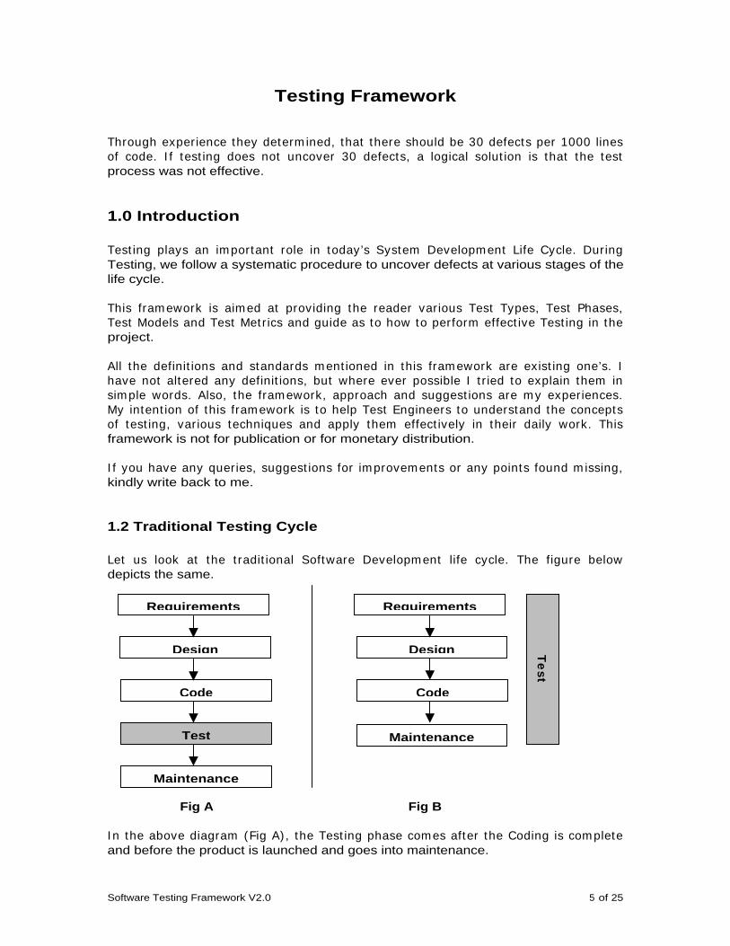
Let us look at the t radit ional Software Developm ent life cycle. The figure below depicts the same.
Fig A Fig B
I n the above diagram (Fig A) , the Test ing phase com es after the Coding is com plete and before the product is launched and goes into maintenance.
Requirements
Design
Code
Test
Maintenance
Requirements
Design
Code
T
est
Maintenance
Software Testing Framework V2.0 6 of 25
But , the recom m ended test process involves test ing in every phase of the life cycle (Fig B) . During the requirem ent phase, the em phasis is upon validat ion to determ ine that the defined requirem ents m eet the needs of the project . During the design and program phases, the em phasis is on verificat ion to ensure that the design and program s accom plish the defined requirem ents. During the test and installat ion phases, the em phasis is on inspect ion to determ ine that the im plem ented system meets the system specification.
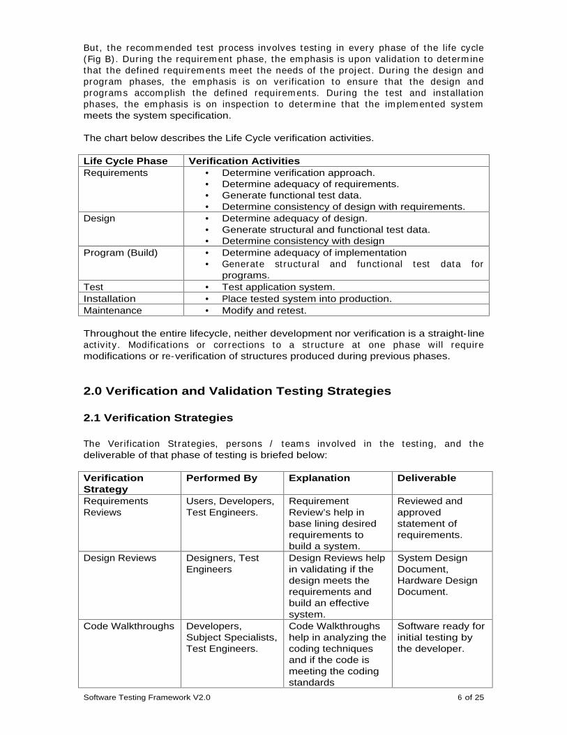
The chart below describes the Life Cycle verification activities.
Life Cycle Phase Verification Activities Requirements • Determine verification approach.
• Determine adequacy of requirements. • Generate functional test data. • Determine consistency of design with requirements.
Design • Determine adequacy of design. • Generate structural and functional test data. • Determine consistency with design
Program (Build) • Determine adequacy of implementation • Generate st ructural and funct ional test data for
programs. Test • Test application system. Installation • Place tested system into production. Maintenance • Modify and retest.
Throughout the entire lifecycle, neither development nor verification is a straight- line act ivity. Modificat ions or correct ions to a st ructure at one phase will require modifications or re-verification of structures produced during previous phases.
2.0 Verification and Validation Testing Strategies
2.1 Verification Strategies
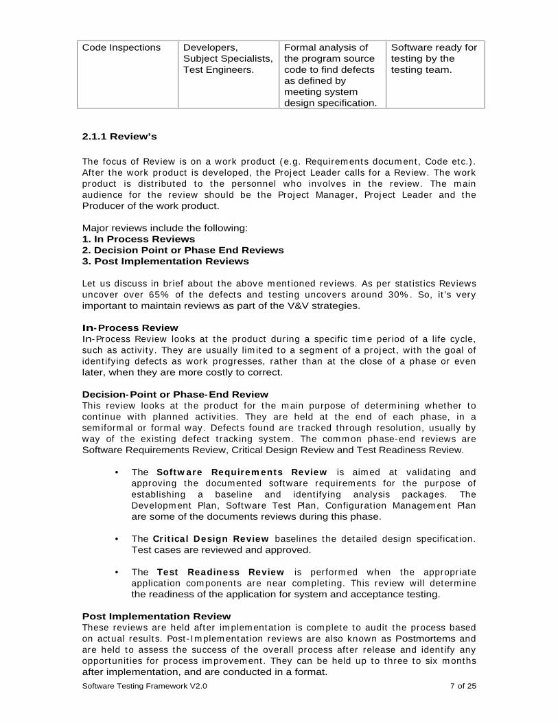
The Verificat ion St rategies, persons / team s involved in the test ing, and the deliverable of that phase of testing is briefed below:
Verification Strategy
Performed By Explanation Deliverable
Requirements Reviews
Users, Developers, Test Engineers.
Requirement Review’s help in base lining desired requirements to build a system.
Reviewed and approved statement of requirements.
Design Reviews Designers, Test Engineers
Design Reviews help in validating if the design meets the requirements and build an effective system.
System Design Document, Hardware Design Document.
Code Walkthroughs Developers, Subject Specialists, Test Engineers.
Code Walkthroughs help in analyzing the coding techniques and if the code is meeting the coding standards
Software ready for initial testing by the developer.
Software Testing Framework V2.0 7 of 25
Code Inspections Developers, Subject Specialists, Test Engineers.
Formal analysis of the program source code to find defects as defined by meeting system design specification.
Software ready for testing by the testing team.
2.1.1 Review’s
The focus of Review is on a work product (e.g. Requirem ents docum ent , Code etc.) . After the work product is developed, the Project Leader calls for a Review. The work product is dist r ibuted to the personnel who involves in the review. The m ain audience for the review should be the Project Manager, Project Leader and the Producer of the work product.
Major reviews include the following: 1. In Process Reviews 2. Decision Point or Phase End Reviews 3. Post Implementation Reviews
Let us discuss in br ief about the above m ent ioned reviews. As per stat ist ics Reviews uncover over 65% of the defects and test ing uncovers around 30% . So, it ’s very important to maintain reviews as part of the V&V strategies.
In-Process Review In-Process Review looks at the product during a specific t im e period of a life cycle, such as act ivity. They are usually lim ited to a segm ent of a project , with the goal of ident ify ing defects as work progresses, rather than at the close of a phase or even later, when they are more costly to correct.
Decision-Point or Phase-End Review This review looks at the product for the m ain purpose of determ ining whether to cont inue with planned act ivit ies. They are held at the end of each phase, in a sem iform al or form al way. Defects found are t racked through resolut ion, usually by way of the exist ing defect t racking system . The com m on phase-end reviews are Software Requirements Review, Critical Design Review and Test Readiness Review.
• The Softw are Requirem ents Review is aim ed at validat ing and approving the docum ented software requirem ents for the purpose of establishing a baseline and ident ify ing analysis packages. The Developm ent Plan, Software Test Plan, Configurat ion Managem ent Plan are some of the documents reviews during this phase.
• The Crit ical Design Review baselines the detailed design specificat ion. Test cases are reviewed and approved.
• The Test Readiness Review is perform ed when the appropriate applicat ion com ponents are near com plet ing. This review will determ ine the readiness of the application for system and acceptance testing.
Post Implementation Review These reviews are held after im plem entat ion is com plete to audit the process based on actual results. Post - I m plem entat ion reviews are also known as Postmortems and are held to assess the success of the overall process after release and ident ify any opportunit ies for process im provem ent . They can be held up to three to six m onths after implementation, and are conducted in a format.
Software Testing Framework V2.0 8 of 25
There are three general classes of reviews: 1. Informal or Peer Review 2. Semiformal or Walk-Through 3. Format or Inspections
Peer Review is generally a one- to-one m eet ing between the author of a work product and a peer, init iated as a request for im port regarding a part icular art ifact or problem . There is no agenda, and results are not form ally reported. These reviews occur on an as needed basis throughout each phase of a project.
2.1.2 Inspections
A knowledgeable individual called a m oderator, who is not a m em ber of the team or the author of the product under review, facilitates inspect ions. A recorder who records the defects found and actions assigned assists the moderator. The meeting is planned in advance and m aterial is dist r ibuted to all the part icipants and the part icipants are expected to at tend the m eet ing well prepared. The issues raised during the m eet ing are docum ented and circulated am ong the m em bers present and the management.
2.1.3 Walkthroughs
The author of the m aterial being reviewed facilitates walk-Through. The part icipants are led through the m aterial in one of two form ats; the presentat ion is m ade without interrupt ions and com m ents are m ade at the end, or com m ents are m ade throughout . I n either case, the issues raised are captured and published in a report dist r ibuted to the part icipants. Possible solut ions for uncovered defects are not discussed during the review.
2.2 Validation Strategies
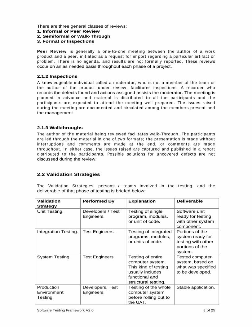
The Validat ion St rategies, persons / team s involved in the test ing, and the deliverable of that phase of testing is briefed below:
Validation Strategy
Performed By Explanation Deliverable
Unit Testing. Developers / Test Engineers.
Testing of single program, modules, or unit of code.
Software unit ready for testing with other system component.
Integration Testing.
Test Engineers. Testing of integrated programs, modules, or units of code.
Portions of the system ready for testing with other portions of the system.
System Testing. Test Engineers. Testing of entire computer system. This kind of testing usually includes functional and structural testing.
Tested computer system, based on what was specified to be developed.
Production Environment Testing.
Developers, Test Engineers.
Testing of the whole computer system before rolling out to the UAT.
Stable application.
Software Testing Framework V2.0 9 of 25
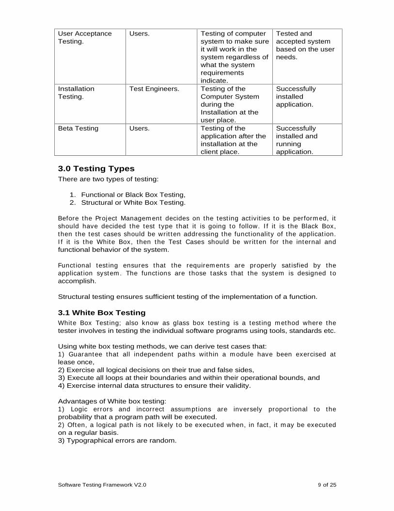
User Acceptance Testing.
Users. Testing of computer system to make sure it will work in the system regardless of what the system requirements indicate.
Tested and accepted system based on the user needs.
Installation Testing.
Test Engineers. Testing of the Computer System during the Installation at the user place.
Successfully installed application.
Beta Testing Users. Testing of the application after the installation at the client place.
Successfully installed and running application.
3.0 Testing Types There are two types of testing:
1. Functional or Black Box Testing, 2. Structural or White Box Testing.
Before the Project Managem ent decides on the test ing act ivit ies to be perform ed, it should have decided the test type that it is going to follow. I f it is the Black Box, then the test cases should be writ ten addressing the funct ionality of the applicat ion. I f it is the White Box, then the Test Cases should be writ ten for the internal and functional behavior of the system.
Funct ional test ing ensures that the requirem ents are properly sat isfied by the applicat ion system . The funct ions are those tasks that the system is designed to accomplish.
Structural testing ensures sufficient testing of the implementation of a function.
3.1 White Box Testing White Box Test ing; also know as glass box test ing is a test ing m ethod where the tester involves in testing the individual software programs using tools, standards etc.
Using white box testing methods, we can derive test cases that: 1) Guarantee that all independent paths within a m odule have been exercised at lease once, 2) Exercise all logical decisions on their true and false sides, 3) Execute all loops at their boundaries and within their operational bounds, and 4) Exercise internal data structures to ensure their validity.
Advantages of White box testing: 1) Logic errors and incorrect assum pt ions are inversely proport ional to the probability that a program path will be executed. 2) Often, a logical path is not likely to be executed when, in fact , it m ay be executed on a regular basis. 3) Typographical errors are random.
Software Testing Framework V2.0 10 of 25
White Box Testing Types There are various types of White Box Test ing. Here in this fram ework I will address the most common and important types.
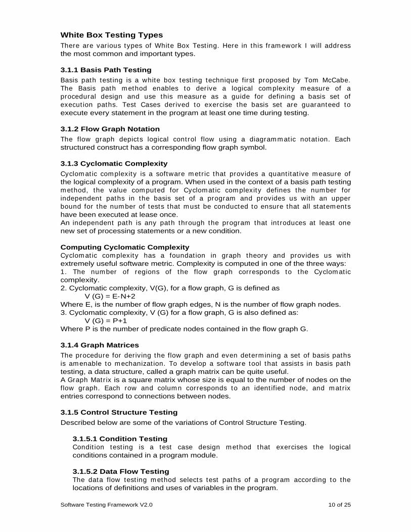
3.1.1 Basis Path Testing
Basis path test ing is a white box test ing technique first proposed by Tom McCabe. The Basis path m ethod enables to derive a logical com plexity m easure of a procedural design and use this m easure as a guide for defining a basis set of execut ion paths. Test Cases derived to exercise the basis set are guaranteed to execute every statement in the program at least one time during testing.
3.1.2 Flow Graph Notation
The flow graph depicts logical cont rol flow using a diagram m at ic notat ion. Each structured construct has a corresponding flow graph symbol.
3.1.3 Cyclomatic Complexity
Cyclom at ic com plexity is a software m et r ic that provides a quant itat ive m easure of the logical complexity of a program. When used in the context of a basis path testing m ethod, the value com puted for Cyclom at ic com plexity defines the num ber for independent paths in the basis set of a program and provides us with an upper bound for the num ber of tests that m ust be conducted to ensure that all statem ents have been executed at lease once. An independent path is any path through the program that int roduces at least one new set of processing statements or a new condition.
Computing Cyclomatic Complexity Cyclom at ic com plexity has a foundat ion in graph theory and provides us with extremely useful software metric. Complexity is computed in one of the three ways: 1. The num ber of regions of the flow graph corresponds to the Cyclom at ic complexity. 2. Cyclomatic complexity, V(G), for a flow graph, G is defined as
V (G) = E-N+2 Where E, is the number of flow graph edges, N is the number of flow graph nodes. 3. Cyclomatic complexity, V (G) for a flow graph, G is also defined as:
V (G) = P+1 Where P is the number of predicate nodes contained in the flow graph G.
3.1.4 Graph Matrices
The procedure for deriving the flow graph and even determ ining a set of basis paths is am enable to m echanizat ion. To develop a software tool that assists in basis path testing, a data structure, called a graph matrix can be quite useful. A Graph Mat r ix is a square matrix whose size is equal to the number of nodes on the flow graph. Each row and colum n corresponds to an ident ified node, and m at r ix entries correspond to connections between nodes.
3.1.5 Control Structure Testing
Described below are some of the variations of Control Structure Testing.
3.1.5.1 Condition Testing Condit ion test ing is a test case design m ethod that exercises the logical conditions contained in a program module.
3.1.5.2 Data Flow Testing The data flow test ing m ethod selects test paths of a program according to the locations of definitions and uses of variables in the program.
Software Testing Framework V2.0 11 of 25
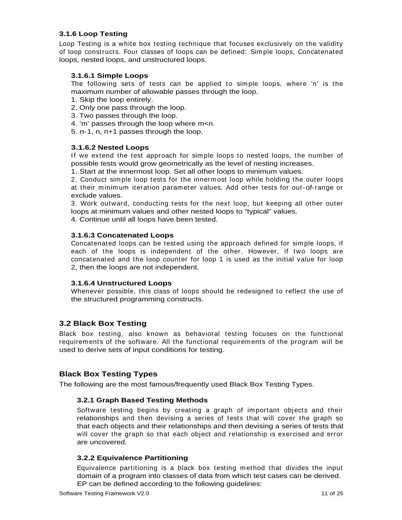
3.1.6 Loop Testing
Loop Test ing is a white box test ing technique that focuses exclusively on the validity of loop const ructs. Four classes of loops can be defined: Sim ple loops, Concatenated loops, nested loops, and unstructured loops.
3.1.6.1 Simple Loops The following sets of tests can be applied to sim ple loops, where ‘n’ is the maximum number of allowable passes through the loop. 1. Skip the loop entirely. 2. Only one pass through the loop. 3. Two passes through the loop. 4. ‘m’ passes through the loop where m<n. 5. n-1, n, n+1 passes through the loop.
3.1.6.2 Nested Loops I f we extend the test approach for sim ple loops to nested loops, the num ber of possible tests would grow geometrically as the level of nesting increases. 1. Start at the innermost loop. Set all other loops to minimum values. 2. Conduct sim ple loop tests for the innerm ost loop while holding the outer loops at their m inim um iterat ion param eter values. Add other tests for out -of- range or exclude values. 3. Work outward, conduct ing tests for the next loop, but keeping all other outer loops at minimum values and other nested loops to “typical” values. 4. Continue until all loops have been tested.
3.1.6.3 Concatenated Loops Concatenated loops can be tested using the approach defined for sim ple loops, if each of the loops is independent of the other. However, if two loops are concatenated and the loop counter for loop 1 is used as the init ial value for loop 2, then the loops are not independent.
3.1.6.4 Unstructured Loops Whenever possible, this class of loops should be redesigned to reflect the use of the structured programming constructs.
3.2 Black Box Testing Black box test ing, also known as behavioral test ing focuses on the funct ional requirem ents of the software. All the funct ional requirem ents of the program will be used to derive sets of input conditions for testing.
Black Box Testing Types The following are the most famous/frequently used Black Box Testing Types.
3.2.1 Graph Based Testing Methods
Software test ing begins by creat ing a graph of im portant objects and their relationships and then devising a series of tests that will cover the graph so that each objects and their relationships and then devising a series of tests that will cover the graph so that each object and relat ionship is exercised and error are uncovered.
3.2.2 Equivalence Partitioning
Equivalence part it ioning is a black box test ing m ethod that divides the input domain of a program into classes of data from which test cases can be derived. EP can be defined according to the following guidelines:

Software Testing Framework V2.0 12 of 25
1. I f an input condit ion specifies a range, one valid and one two invalid classes are defined. 2. I f an input condit ion requires a specific value, one valid and two invalid equivalence classes are defined. 3. I f an input condit ion specifies a m em ber of a set , one valid and one invalid equivalence class are defined. 4. If an input condition is Boolean, one valid and one invalid class are defined.
3.2.3 Boundary Value Analysis
BVA is a test case design technique that com plem ents equivalence part it ioning. Rather than select ing any elem ent of an equivalence class, BVA leads to the select ion of test cases at the “edges” of the class. Rather than focusing solely on input conditions, BVA derives test cases from the output domain as well. Guidelines for BVA are sim ilar in m any respects to those provided for equivalence partitioning.
3.2.4 Comparison Testing
Situat ions where independent versions of software be developed for cr it ical applicat ions, even when only a single version will be used in the delivered com puter based system . These independent versions from the basis of a black box testing technique called Comparison testing or back- to-back testing.
3.2.5 Orthogonal Array Testing
The orthogonal array testing method is particularly useful in finding errors associated with region faults – an error category associated with faulty logic within a software component.
3.3 Scenario Based Testing (SBT) Dr.Cem Kaner
in “A Pat tern for Scenario Test ing” has explained scenario Based Testing in great detail that can be found at www.testing.com.
What is Scenario Based Test ing and How/ Where is it useful is an interest ing question. I shall explain in brief the above two mentioned points.
Scenario Based Test ing is categorized under Black Box Tests and are m ost helpful when the test ing is concent rated on the Business logic and funct ional behavior of the applicat ion. Adopt ing SBT is effect ive when test ing com plex applicat ions. Now, every applicat ion is com plex, then it ’s the team s call as to im plem ent SBT or not . I would personally suggest using SBT when the funct ionality to test includes various features and funct ions. A best exam ple would be while test ing banking applicat ion. As banking applicat ions require utm ost care while test ing, handling various funct ions in a single scenario would result in effective results. A sam ple t ransact ion (scenario) can be, a custom er logging into the applicat ion, checking his balance, t ransferr ing am ount to another account , paying his bills, checking his balance again and logging out.
In brief, use Scenario Based Tests when: 1. Testing complex applications. 2. Testing Business functionality.
When designing scenarios, keep in mind: 1. The scenario should be close to the real life scenario. 2. Scenarios should be realistic. 3. Scenarios should be traceable to any/combination of functionality. 4. Scenarios should be supported by sufficient data.
Software Testing Framework V2.0 13 of 25
3.4 Exploratory Testing Exploratory Tests are categorized under Black Box Tests and are aim ed at test ing in conditions when sufficient time is not available for testing or proper documentation is not available.
Exploratory testing is ‘Testing while Exploring’. When you have no idea of how the application works, exploring the application with the intent of finding errors can be termed as Exploratory Testing.
Performing Exploratory Testing This is one big question for many people. The following can be used to perform Exploratory Testing:
• Learn the Application. • Learn the Business for which the application is addressed. • Learn the technology to the maximum extent on which the application has
been designed. • Learn how to test. • Plan and Design tests as per the learning.
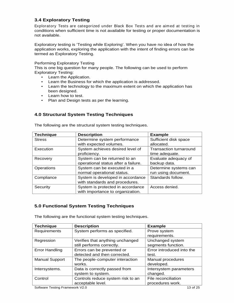
4.0 Structural System Testing Techniques
The following are the structural system testing techniques.
Technique Description Example Stress Determine system performance
with expected volumes. Sufficient disk space allocated.
Execution System achieves desired level of proficiency.
Transaction turnaround time adequate.
Recovery System can be returned to an operational status after a failure.
Evaluate adequacy of backup data.
Operations System can be executed in a normal operational status.
Determine systems can run using document.
Compliance System is developed in accordance with standards and procedures.
Standards follow.
Security System is protected in accordance with importance to organization.
Access denied.
5.0 Functional System Testing Techniques
The following are the functional system testing techniques.
Technique Description Example Requirements System performs as specified. Prove system
requirements. Regression Verifies that anything unchanged
still performs correctly. Unchanged system segments function.
Error Handling Errors can be prevented or detected and then corrected.
Error introduced into the test.
Manual Support The people-computer interaction works.
Manual procedures developed.
Intersystems. Data is correctly passed from system to system.
Intersystem parameters changed.
Control Controls reduce system risk to an acceptable level.
File reconciliation procedures work.
Software Testing Framework V2.0 14 of 25
Parallel Old systems and new system are run and the results compared to detect unplanned differences.
Old and new system can reconcile.
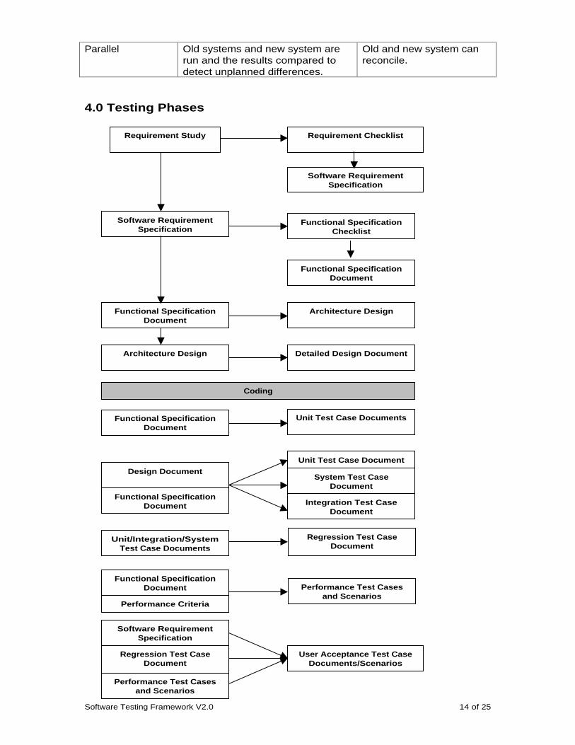
4.0 Testing Phases
Requirement Study
Software Requirement Specification
Requirement Checklist
Software Requirement Specification
Functional Specification Checklist
Functional Specification Document
Functional Specification Document
Architecture Design
Architecture Design Detailed Design Document
Coding
Functional Specification Document
Unit Test Case Documents
Design Document
Functional Specification Document
Unit Test Case Document
System Test Case Document
Integration Test Case Document
Unit/Integration/System Test Case Documents
Regression Test Case Document
Functional Specification Document
Performance Criteria
Performance Test Cases and Scenarios
Software Requirement Specification
Regression Test Case Document
Performance Test Cases and Scenarios
User Acceptance Test Case Documents/Scenarios
Software Testing Framework V2.0 15 of 25
4.2 Unit Testing
Goal of Unit test ing is to uncover defects using form al techniques like Boundary Value Analysis (BVA) , Equivalence Part it ioning, and Error Guessing. Defects and deviat ions in Date form ats, Special requirem ents in input condit ions ( for exam ple Text box where only num eric or alphabets should be entered) , select ion based on Com bo Box’s, List Box’s, Opt ion but tons, Check Box’s would be ident ified during the Unit Testing phase.
4.3 Integration Testing
I ntegrat ion test ing is a system at ic technique for const ruct ing the program st ructure while at the sam e t im e conduct ing tests to uncover errors associated with interfacing. The object ive is to take unit tested com ponents and build a program structure that has been dictated by design. Usually, the following methods of Integration testing are followed:
1. Top-down Integration approach. 2. Bottom-up Integration approach.
4.3.1 Top-down Integration
Top-down integrat ion test ing is an increm ental approach to const ruct ion of program st ructure. Modules are integrated by m oving downward through the cont rol hierarchy, beginning with the m ain cont rol m odule. Modules subordinate to the m ain cont rol m odule are incorporated into the st ructure in either a depth- first or breadth-first manner.
1. The Integration process is performed in a series of five steps: 2. The main control module is used as a test driver and stubs are substituted for
all components directly subordinate to the main control module. 3. Depending on the integrat ion approach selected subordinate stubs are
replaced one at a time with actual components. 4. Tests are conducted as each component is integrated. 5. On com plet ion of each set of tests, another stub is replaced with the real
component. 6. Regression test ing m ay be conducted to ensure that new errors have not
been introduced.
4.3.2 Bottom-up Integration
Button-up integrat ion test ing begins const ruct ion and test ing with atom ic m odules (i.e. components at the lowest levels in the program structure). Because components are integrated from the but ton up, processing required for com ponents subordinate to a given level is always available and the need for stubs is eliminated.
1. A Bot tom -up integrat ion st rategy m ay be im plem ented with the following steps:
2. Low level com ponents are com bined into clusters that perform a specific software sub function.
3. A driver is written to coordinate test case input and output. 4. The cluster is tested. 5. Drivers are rem oved and clusters are com bined m oving upward in the
program structure.
Software Testing Framework V2.0 16 of 25
4.4 Smoke Testing
“Smoke testing might be a characterized as a rolling integration strategy”. Sm oke test ing is an integrat ion test ing approach that is com m only used when “shrink-wrapped” software products are being developed. I t is designed as a pacing m echanism for t im e-critical projects, allowing the software team to assess its project on a frequent basis. The sm oke test should exercise the ent ire system from end to end. Sm oke test ing provides benefits such as: 1) Integration risk is minimized. 2) The quality of the end-product is improved. 3) Error diagnosis and correction are simplified. 4) Progress is easier to asses.
4.5 System Testing
System test ing is a series of different tests whose prim ary purpose is to fully exercise the com puter based system . Although each test has a different purpose, all work to verify that system elem ents have been properly integrated and perform allocated functions. The following tests can be categorized under System testing:
1. Recovery Testing. 2. Security Testing. 3. Stress Testing. 4. Performance Testing.
4.5.1. Recovery Testing
Recovery test ing is a system test that focuses the software to fall in a variety of ways and verifies that recovery is properly perform ed. I f recovery is autom at ic, reinit ializat ion, checkpoint ing m echanism s, data recovery and restart are evaluated for correctness. I f recovery requires hum an intervent ion, the m ean- time-to-repair (MTTR) is evaluated to determine whether it is within acceptable limits.
4.5.2. Security Testing
Security test ing at tem pts to verify that protect ion m echanism s built into a system will, in fact , protect it from im proper penet rat ion. During Security test ing, password cracking, unauthorized ent ry into the software, network security are all taken into consideration.
4.5.3. Stress Testing
St ress test ing executes a system in a m anner that dem ands resources in abnorm al quant ity, frequency, or volum e. The following types of tests m ay be conducted during stress testing;
• Special tests m ay be designed that generate ten interrupts per second, when one or two is the average rate.
• I nput data rates m ay be increases by an order of m agnitude to determine how input functions will respond.
• Test Cases that require maximum memory or other resources. • Test Cases that may cause excessive hunting for disk-resident data. • Test Cases that my cause thrashing in a virtual operating system.
4.5.4. Performance Testing
Perform ance tests are coupled with st ress test ing and usually require both hardware and software instrumentation.
Software Testing Framework V2.0 17 of 25
4.5.5. Regression Testing
Regression testing is the re-execution of some subset of tests that have already been conducted to ensure that changes have not propagated unintended side affects. Regression may be conducted manually, by re-executing a subset of al test cases or using automated capture/playback tools. The Regression test suit contains three different classes of test cases:
• A representative sample of tests that will exercise all software functions. • Additional tests that focus on software functions that are likely to be
affected by the change. • Tests that focus on the software components that have been changed.
4.6 Alpha Testing The Alpha testing is conducted at the developer sites and in a controlled environment by the end-user of the software.
4.7 User Acceptance Testing User Acceptance test ing occurs just before the software is released to the custom er. The end-users along with the developers perform the User Acceptance Testing with a certain set of test cases and typical scenarios.
4.8 Beta Testing The Beta test ing is conducted at one or m ore custom er sites by the end-user of the software. The beta test is a live applicat ion of the software in an environm ent that cannot be controlled by the developer.
5.0 Metrics Metrics are the m ost im portant responsibilit y of the Test Team . Met r ics allow for deeper understanding of the perform ance of the applicat ion and its behavior. The fine tuning of the applicat ion can be enhanced only with m et r ics. I n a typical QA process, there are many metrics which provide information.
The following can be regarded as the fundamental metric:
IEEE Std 982.2 - 1988 defines a Functional or Test Coverage Metric. It can be used to measure test coverage prior to software delivery. It provide a measure of the percentage of the software tested at any point during testing. It is calculated as follows: Function Test Coverage = FE/FT Where FE is the number of test requirements that are covered by test cases that were executed against the software FT is the total number of test requirements
Software Release Metrics The software is ready for release when: 1. It has been tested with a test suite that provides 100% functional coverage, 80% branch coverage, and 100% procedure coverage. 2. There are no level 1 or 2 severity defects. 3. The defect finding rate is less than 40 new defects per 1000 hours of testing 4. The software reaches 1000 hours of operation 5. Stress testing, configuration testing, installation testing, Naïve user testing, usability testing, and sanity testing have been completed
Software Testing Framework V2.0 18 of 25
IEEE Software Maturity Metric IEEE Std 982.2 - 1988 defines a Software Maturity Index that can be used to determine the readiness for release of a software system. This index is especially useful for assessing release readiness when changes, additions, or deletions are made to existing software systems. It also provides an historical index of the impact of changes. It is calculated as follows: SMI = Mt - ( Fa + Fc + Fd)/Mt Where SMI is the Software Maturity Index value Mt is the number of software functions/modules in the current release Fc is the number of functions/modules that contain changes from the previous release Fa is the number of functions/modules that contain additions to the previous release Fd is the number of functions/modules that are deleted from the previous release
Reliability Metrics Perry offers the following equation for calculating reliability. Reliability = 1 - Number of errors (actual or predicted)/Total number of lines of executable code This reliability value is calculated for the number of errors during a specified time interval. Three other metrics can be calculated during extended testing or after the system is in production. They are: MTTFF (Mean Time to First Failure) MTTFF = The number of time intervals the system is operable until its first failure MTBF (Mean Time Between Failures) MTBF = Sum of the time intervals the system is operable Number of failures for the time period MTTR (Mean Time To Repair) MTTR = sum of the time intervals required to repair the system The number of repairs during the time period
Software Testing Framework V2.0 19 of 25
6.0 Test Models There are various models of Software Testing. Here in this framework I would explain the three most commonly used models:
1. The ‘V’ Model. 2. The ‘W’ Model. 3. The Butterfly Model
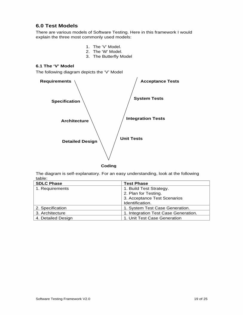
6.1 The ‘V’ Model
The following diagram depicts the ‘V’ Model
The diagram is self-explanatory. For an easy understanding, look at the following table: SDLC Phase Test Phase 1. Requirements 1. Build Test Strategy.
2. Plan for Testing. 3. Acceptance Test Scenarios Identification.
2. Specification 1. System Test Case Generation. 3. Architecture 1. Integration Test Case Generation. 4. Detailed Design 1. Unit Test Case Generation
Unit Tests
Integration Tests
System Tests
Acceptance Tests
Detailed Design
Architecture
Specification
Requirements
Coding
Software Testing Framework V2.0 20 of 25
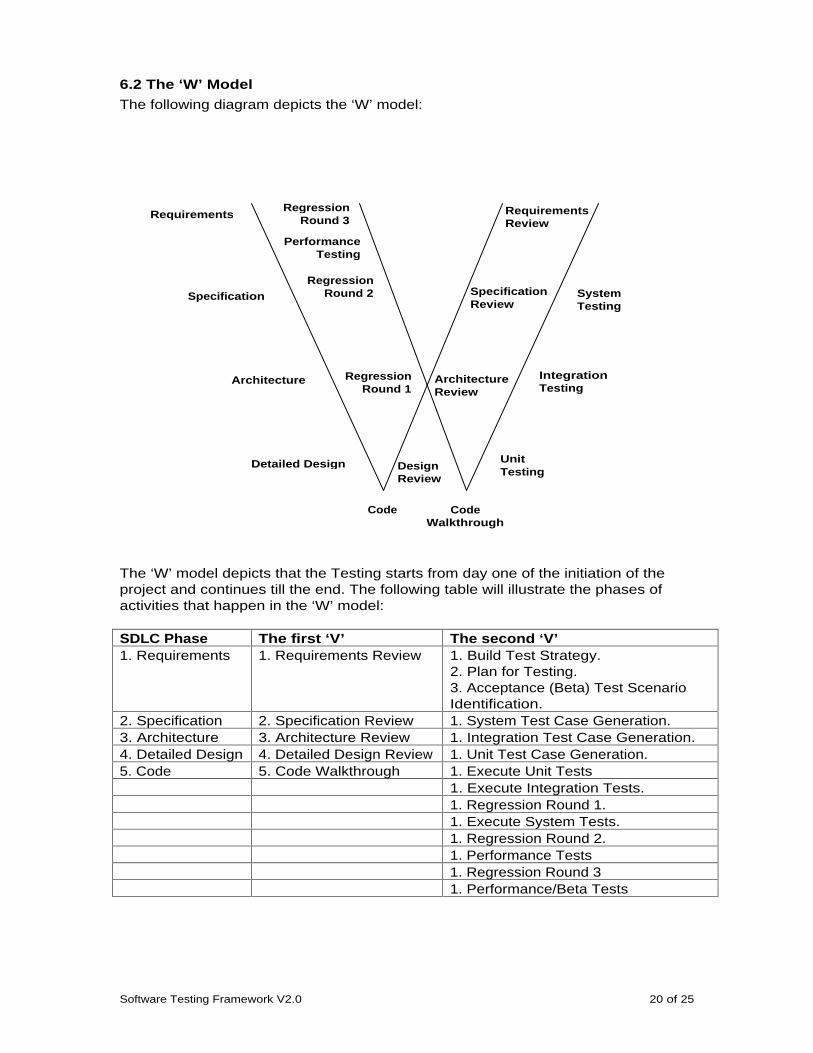
6.2 The ‘W’ Model
The following diagram depicts the ‘W’ model:
The ‘W’ model depicts that the Testing starts from day one of the initiation of the project and continues till the end. The following table will illustrate the phases of activities that happen in the ‘W’ model:
SDLC Phase The first ‘V’ The second ‘V’ 1. Requirements 1. Requirements Review 1. Build Test Strategy.
2. Plan for Testing. 3. Acceptance (Beta) Test Scenario Identification.
2. Specification 2. Specification Review 1. System Test Case Generation. 3. Architecture 3. Architecture Review 1. Integration Test Case Generation. 4. Detailed Design
4. Detailed Design Review 1. Unit Test Case Generation. 5. Code 5. Code Walkthrough 1. Execute Unit Tests
1. Execute Integration Tests.
1. Regression Round 1.
1. Execute System Tests.
1. Regression Round 2.
1. Performance Tests
1. Regression Round 3
1. Performance/Beta Tests
Regression
Round 3
Performance Testing
Regression Round 2
Regression Round 1
Design Review
Architecture Review
Specification Review
Requirements Review
Requirements
Specification
Architecture
Detailed Design Unit Testing
Integration Testing
System Testing
Code
Code Walkthrough

Software Testing Framework V2.0 21 of 25
In the second ‘V’, I have mentioned Acceptance/Beta Test Scenario Identification. This is because, the customer might want to design the Acceptance Tests. In this case as the development team executes the Beta Tests at the client place, the same team can identify the Scenarios.
Regression Rounds are performed at regular intervals to check whether the defects, which have been raised and fixed, are re- tested.
6.3 The Butterfly Model
The test ing act ivit ies for test ing software products are preferable to follow the Butterfly Model. The following picture depicts the test methodology.
Fig: Butterfly Model
I n the Butterfly m odel of Test Developm ent , the left wing of the but terfly depicts the Test Analysis. The r ight wing depicts the Test Design , and finally the body of the but terfly depicts the Test Execut ion . How this exact ly happens is described below.
Test Analysis
Analysis is the key factor which drives in any planning. During the analysis, the analyst understands the following:
• Verify that each requirem ent is tagged in a m anner that allows correlat ion of the tests for that requirement to the requirement itself. (Establish Test Traceability)
• Verify traceability of the software requirements to system requirements. • Inspect for contradictory requirements. • Inspect for ambiguous requirements. • Inspect for missing requirements. • Check to m ake sure that each requirem ent , as well as the specificat ion as a
whole, is understandable. • I dent ify one or m ore m easurem ent , dem onst rat ion, or analysis m ethod that m ay
be used to verify the requirement’s implementation (during formal testing). • Create a test “ sketch” that includes the tentat ive approach and indicates the
test’s objectives. During Test Analysis the required docum ents will be carefully studied by the Test Personnel, and the final Analysis Report is documented. The following documents would be usually referred:
1. Software Requirements Specification. 2. Functional Specification. 3. Architecture Document.
Test Analysis
Test Execution
Test Design
Software Testing Framework V2.0 22 of 25
4. Use Case Documents.
The Analysis Report would consist of the understanding of the applicat ion, the funct ional flow of the applicat ion, num ber of m odules involved and the effect ive Test Time.
Test Design The r ight wing of the but terfly represents the act of designing and im plem ent ing the test cases needed to verify the design art ifact as replicated in the im plem entat ion. Like test analysis, it is a relatively large piece of work. Unlike test analysis, however, the focus of test design is not to assim ilate inform at ion created by others, but rather to im plem ent procedures, techniques, and data sets that achieve the test ’s objective(s). The outputs of the test analysis phase are the foundat ion for test design. Each requirem ent or design const ruct has had at least one technique (a m easurem ent , dem onst rat ion, or analysis) ident ified during test analysis that will validate or verify that requirement. The tester must now implement the intended technique. Software test design, as a discipline, is an exercise in the prevent ion, detect ion, and elim inat ion of bugs in software. Prevent ing bugs is the pr im ary goal of software test ing. Diligent and com petent test design prevents bugs from ever reaching the im plem entat ion stage. Test design, with its at tendant test analysis foundat ion, is therefore the prem iere weapon in the arsenal of developers and testers for lim it ing the cost associated with finding and fixing bugs. During Test Design, basing on the Analysis Report the test personnel would develop the following:
1. Test Plan. 2. Test Approach. 3. Test Case documents. 4. Performance Test Parameters. 5. Performance Test Plan.
Test Execution
Any test case should adhere to the following principals: 1. Accurate – tests what the description says it will test. 2. Economical – has only the steps needed for its purpose. 3. Repeatable – tests should be consistent, no matter who/when it is executed. 4. Appropriate – should be apt for the situation. 5. Traceable – the functionality of the test case should be easily found.
During the Test Execut ion phase, keeping the Project and the Test schedule, the test cases designed would be executed. The following docum ents will be handled during the test execution phase: 1. Test Execution Reports. 2. Daily/Weekly/monthly Defect Reports. 3. Person wise defect reports.
After the Test Execution phase, the following documents would be signed off.
1. Project Closure Document. 2. Reliability Analysis Report. 3. Stability Analysis Report. 4. Performance Analysis Report. 5. Project Metrics.
Software Testing Framework V2.0 23 of 25
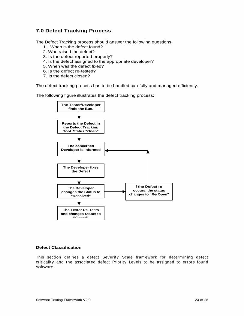
7.0 Defect Tracking Process
The Defect Tracking process should answer the following questions: 1. When is the defect found? 2. Who raised the defect? 3. Is the defect reported properly? 4. Is the defect assigned to the appropriate developer? 5. When was the defect fixed? 6. Is the defect re- tested? 7. Is the defect closed?
The defect tracking process has to be handled carefully and managed efficiently.
The following figure illustrates the defect tracking process:
Defect Classification
This sect ion defines a defect Severity Scale fram ework for determ ining defect cr it icality and the associated defect Prior ity Levels to be assigned to errors found software.
The Tester/Developer finds the Bug.
Reports the Defect in the Defect Tracking Tool. Status “Open”
The concerned Developer is informed
The Developer fixes the Defect
The Developer changes the Status to
“Resolved”
The Tester Re- Tests and changes Status to
“Closed”
If the Defect re-occurs, the status
changes to “Re- Open”
Software Testing Framework V2.0 24 of 25
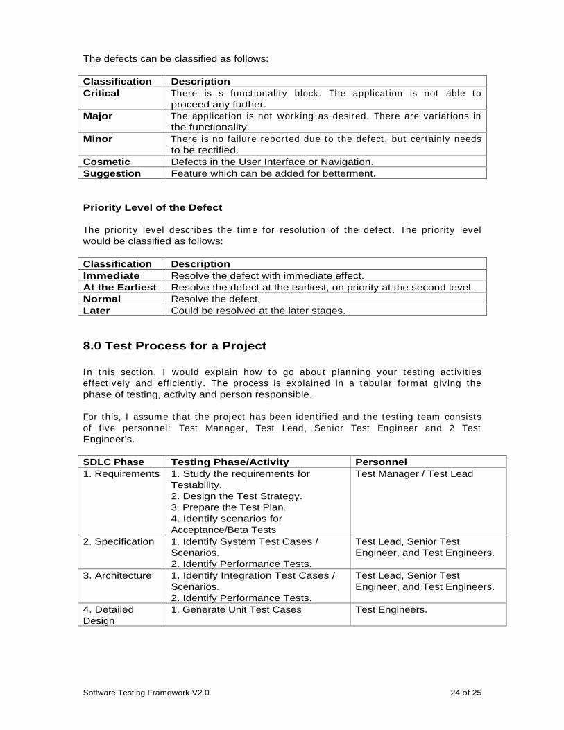
The defects can be classified as follows:
Classification Description Critical There is s funct ionality block. The applicat ion is not able to
proceed any further. Major The applicat ion is not working as desired. There are variat ions in
the functionality. Minor There is no failure reported due to the defect , but certainly needs
to be rectified. Cosmetic Defects in the User Interface or Navigation. Suggestion Feature which can be added for betterment.
Priority Level of the Defect
The prior ity level describes the t im e for resolut ion of the defect . The prior ity level would be classified as follows:
Classification Description Immediate Resolve the defect with immediate effect. At the Earliest Resolve the defect at the earliest, on priority at the second level. Normal Resolve the defect. Later Could be resolved at the later stages.
8.0 Test Process for a Project
I n this sect ion, I would explain how to go about planning your test ing act ivit ies effect ively and efficient ly. The process is explained in a tabular form at giving the phase of testing, activity and person responsible.
For this, I assum e that the project has been ident ified and the test ing team consists of five personnel: Test Manager, Test Lead, Senior Test Engineer and 2 Test Engineer’s.
SDLC Phase Testing Phase/Activity Personnel 1. Requirements 1. Study the requirements for
Testability. 2. Design the Test Strategy. 3. Prepare the Test Plan. 4. Identify scenarios for Acceptance/Beta Tests
Test Manager / Test Lead
2. Specification 1. Identify System Test Cases / Scenarios. 2. Identify Performance Tests.
Test Lead, Senior Test Engineer, and Test Engineers.
3. Architecture 1. Identify Integration Test Cases / Scenarios. 2. Identify Performance Tests.
Test Lead, Senior Test Engineer, and Test Engineers.
4. Detailed Design
1. Generate Unit Test Cases Test Engineers.
Software Testing Framework V2.0 25 of 25
9.0 Deliverables The Deliverables from the Test team would include the following:
1. Test Strategy. 2. Test Plan. 3. Test Case Documents. 4. Defect Reports. 5. Status Reports (Daily/weekly/Monthly). 6. Test Scripts (if any). 7. Metric Reports. 8. Product Sign off Document.