soft soils improved by prefabricated vertical drains ... · soft soils improved by prefabricated...
TRANSCRIPT
University of WollongongResearch Online
Faculty of Engineering - Papers (Archive) Faculty of Engineering and Information Sciences
2010
Soft soils improved by prefabricated vertical drains:performance and predictionBuddhima IndraratnaUniversity of Wollongong, [email protected]
Cholachat RujikiatkamjornUniversity of Wollongong, [email protected]
V Wijeyakulasuriya
G McIntosh
R Kelly
http://ro.uow.edu.au/engpapers/870
Research Online is the open access institutional repository for the University of Wollongong. For further information contact the UOW Library:[email protected]
Publication DetailsIndraratna, B, Rujikiatkamjorn, C, Wijeyakulasuriya, V, McIntosh, G & Kelly, R, Soft soils improved by prefabricated vertical drains:performance and prediction, In Almeida, M (ed), Symposium on New Techniques for Design and Construction in Soft Clays, 2010,227-246, Brazil: Officna de Textos.
Soft soils improved by prefabricated vertical drains: performance and prediction
Indraratna, B. and Rujikiatkamjorn, C. School of Civil, Mining and Environmental engineering, Faculty of Engineering, University of Wollongong, Wollongong City, Australia
Wijeyakulasuriya, V. Queensland Department. of Main Roads, Brisbane, Australia
McIntosh, G. Douglas Partners Pty Ltd, Unanderra, NSW Australia
Kelly, R. Coffey Geotechnics, Sydney, Australia. KEYWORDS Analytical model, Cyclic loading, Numerical model, Soft soils, Vacuum preloading, Vertical drains
ABSTRACT The use of prefabricated vertical drains with preloading is now common practice and is proving to be one of the most effective ground improvement techniques known. The factors affecting its performance, such as the smear zone, the drain influence zone, and drain unsaturation, are discussed in this paper. In order to evaluate these effects a large scale consolidation test was conducted and it was found that the proposed Cavity Expansion Theory could be used to predict the characteristics of the smear zone based on the soil properties available. Moreover, the procedure for converting an equivalent 2-D plane strain multi-drain analysis that considers the smear zone and vacuum pressure are also described. The conversion procedure was incorporated into finite element codes using a modified Cam-clay theory. Numerical analysis was conducted to predict excess pore pressure and lateral and vertical displacement. Three case histories are analysed and discussed, including the sites of Muar clay (Malaysia), the Second Bangkok International Airport (Thailand), and the Sandgate railway line (Australia). The predictions were then compared with the available field data, and they include settlement, excess pore pressure, and lateral displacement. The findings verified that smear and well resistance can significantly affect soil consolidation, which means that these aspects must be simulated appropriately to reliably predict consolidation using a selected numerical approach. Further findings verified that smear, drain unsaturation, and vacuum distribution can significantly influence consolidation so they must be modeled appropriately in any numerical analysis to obtain reliable predictions.
1 INTRODUCTION
Preloading of soft clay with vertical drains is one of the most popular
methods used to increase the shear strength of soft soil and control its
post-construction settlement. Since the permeability of soils is very low,
consolidation time to the achieved desired settlement or shear strength
may take too long (Holtz, 1987; Indraratna et al., 1994). Using
prefabricated vertical drains (PVDs), means that the drainage path is
shortened from the thickness of the soil layer to the radius of the drain
influence zone, which accelerates consolidation (Hansbo, 1981). This
system has been used to improve the properties of foundation soil for
railway embankments, airports, and highways (Li and Rowe, 2002).
Over the past three decades the performance of various types of
vertical drains, including sand drains, sand compaction piles, prefabricated
vertical drains (geosynthetic) and gravel piles, have been studied. Kjellman
(1948) introduced prefabricated band shaped drains and cardboard wick
drains for ground improvement. Typically, prefabricated band drains
consist of a plastic core with a longitudinal channel surrounded by a filter
jacket to prevent clogging. Most vertical drains are approximately 100 mm
wide and 4 mm thick.
To study consolidation due to PVDs, unit cell analysis with a single
drain surrounded by a soil cylinder has usually been proposed (e.g. Barron,
1948; Yoshikuni and Nakanodo, 1974). PVDs under an embankment not
only accelerate consolidation, they also influence the pattern of subsoil
deformation. At the centre line of an embankment where lateral
displacement is negligible, unit cell solutions are sufficient but elsewhere,
especially towards the embankment toe, any prediction from a single drain
analysis is not accurate enough because of lateral deformation and heave
(Indraratna, et al., 1997).
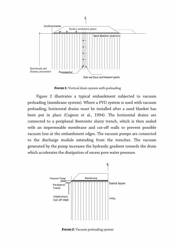
Figure 1 shows the vertical cross section of an embankment stabilised
by a vertical drain system, with the instruments required to monitor the
soil foundation. Before PVDs are installed superficial soil must be removed
to ease the installation of the horizontal drainage, the site must be graded,
and a sand platform compacted. The sand blanket drains water from the
PVDs and supports the vertical drain installation rigs.
CL
Sand Blanket/platform
Sub-surface settlement plate
Piezometer
InclinometerSurface settlement plates
Benchmark andDummy piezometer
FIGURE 1: Vertical drain system with preloading
Figure 2 illustrates a typical embankment subjected to vacuum
preloading (membrane system). Where a PVD system is used with vacuum
preloading, horizontal drains must be installed after a sand blanket has
been put in place (Cognon et al., 1994). The horizontal drains are
connected to a peripheral Bentonite slurry trench, which is then sealed
with an impermeable membrane and cut-off walls to prevent possible
vacuum loss at the embankment edges. The vacuum pumps are connected
to the discharge module extending from the trenches. The vacuum
generated by the pump increases the hydraulic gradient towards the drain
which accelerates the dissipation of excess pore water pressure.
CL
Sand layer
Vacuum Pump Membrane
PeripheralTrench
ImperviousCut-off Wall PVDs
FIGURE 2: Vacuum preloading system
2 VERTICAL DRAIN CHARACTERISTICS
2.1 Equivalent drain diameter and drain influence zone
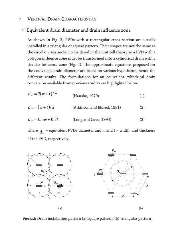
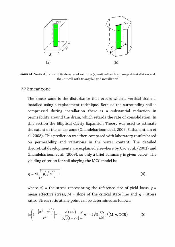
As shown in Fig. 3, PVDs with a rectangular cross section are usually
installed in a triangular or square pattern. Their shapes are not the same as
the circular cross section considered in the unit cell theory so a PVD with a
polygon influence zone must be transformed into a cylindrical drain with a
circular influence zone (Fig. 4). The approximate equations proposed for
the equivalent drain diameter are based on various hypotheses, hence the
different results. The formulations for an equivalent cylindrical drain
conversion available from previous studies are highlighted below:
( ) π/2 twdw += (Hansbo, 1979) (1)
( ) 2/twdw += (Atkinson and Eldred, 1981) (2)
twdw 7.05.0 += (Long and Covo, 1994) (3)
where wd = equivalent PVDs diameter and w and t = width and thickness
of the PVD, respectively.
de
wt
S
S
dw
dew
t
dw
S
S
(a) (b)
FIGURE 3: Drain installation pattern (a) square pattern; (b) triangular pattern
SS
PVD
PVD
S
(a) (b)
FIGURE 4: Vertical drain and its dewatered soil zone (a) unit cell with square grid installation and (b) unit cell with triangular grid installation
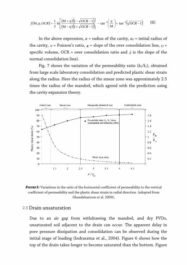
2.2 Smear zone
The smear zone is the disturbance that occurs when a vertical drain is
installed using a replacement technique. Because the surrounding soil is
compressed during installation there is a substantial reduction in
permeability around the drain, which retards the rate of consolidation. In
this section the Elliptical Cavity Expansion Theory was used to estimate
the extent of the smear zone (Ghandeharioon et al. 2009; Sathananthan et
al. 2008). This prediction was then compared with laboratory results based
on permeability and variations in the water content. The detailed
theoretical developments are explained elsewhere by Cao et al. (2001) and
Ghandeharioon et al. (2009), so only a brief summary is given below. The
yielding criterion for soil obeying the MCC model is:
1'' −⎟⎠⎞⎜
⎝⎛Μ= ppcη (4)
where p’c = the stress representing the reference size of yield locus, p’=
mean effective stress, M = slope of the critical state line and η = stress
ratio. Stress ratio at any point can be determined as follows:
( ) ( )( )
( )OCRfr
aa,,32
2133121ln
2
20
2
ηυκη
υκ
νν
ΜΜΛ
−−
+−=⎟
⎟⎠
⎞⎜⎜⎝
⎛ −− (5)
( ) ( ) ( )( ) ( ) ( )1tantan
1111ln
21,, 11 −+⎟
⎠⎞
⎜⎝⎛
Μ−
⎥⎥⎦
⎤
⎢⎢⎣
⎡
−+−Μ
−−+Μ=Μ −− OCR
OCROCROCRf η
ηηη (6)
In the above expression, a = radius of the cavity, a0 = initial radius of
the cavity, ν = Poisson’s ratio, κ = slope of the over consolidation line, υ =
specific volume, OCR = over consolidation ratio and λ is the slope of the
normal consolidation line).
Fig. 7 shows the variation of the permeability ratio (kh/kv), obtained
from large scale laboratory consolidation and predicted plastic shear strain
along the radius. Here the radius of the smear zone was approximately 2.5
times the radius of the mandrel, which agreed with the prediction using
the cavity expansion theory.
FIGURE 5: Variations in the ratio of the horizontal coefficient of permeability to the vertical coefficient of permeability and the plastic shear strain in radial direction (adopted from
Ghandeharioon et al. 2009),
2.3 Drain unsaturation
Due to an air gap from withdrawing the mandrel, and dry PVDs,
unsaturated soil adjacent to the drain can occur. The apparent delay in
pore pressure dissipation and consolidation can be observed during the
initial stage of loading (Indraratna et al., 2004). Figure 6 shows how the
top of the drain takes longer to become saturated than the bottom. Figure
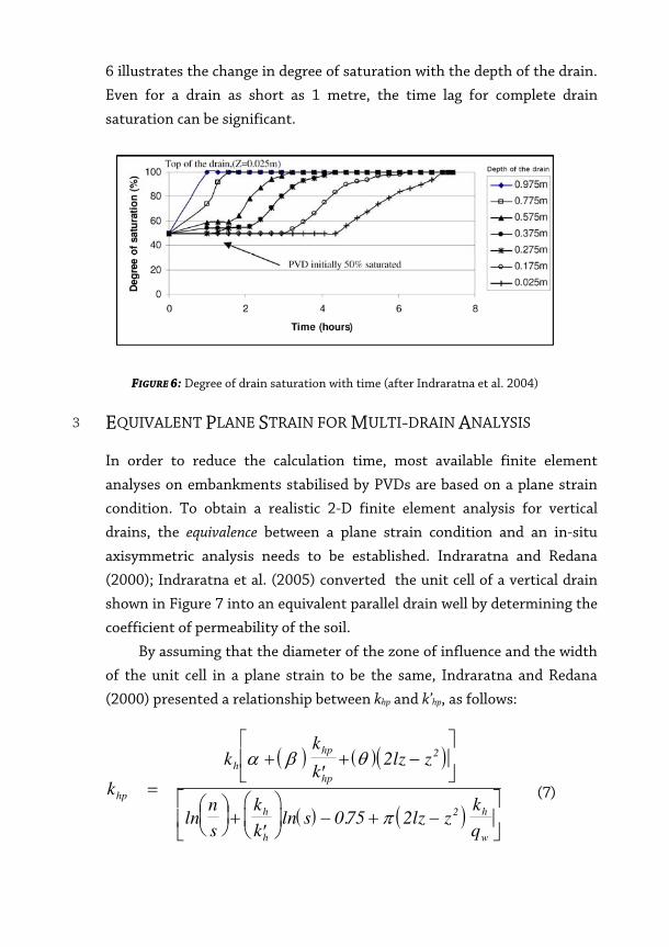
6 illustrates the change in degree of saturation with the depth of the drain.
Even for a drain as short as 1 metre, the time lag for complete drain
saturation can be significant.
FIGURE 6: Degree of drain saturation with time (after Indraratna et al. 2004)
3 EQUIVALENT PLANE STRAIN FOR MULTI-DRAIN ANALYSIS
In order to reduce the calculation time, most available finite element
analyses on embankments stabilised by PVDs are based on a plane strain
condition. To obtain a realistic 2-D finite element analysis for vertical
drains, the equivalence between a plane strain condition and an in-situ
axisymmetric analysis needs to be established. Indraratna and Redana
(2000); Indraratna et al. (2005) converted the unit cell of a vertical drain
shown in Figure 7 into an equivalent parallel drain well by determining the
coefficient of permeability of the soil.
By assuming that the diameter of the zone of influence and the width
of the unit cell in a plane strain to be the same, Indraratna and Redana
(2000) presented a relationship between khp and k’hp, as follows:
( ) ( )( )
( ) ( )k
kk
klz z
n
s
k
ks lz z
k
q
hp
h
hp
hp
h
h
h
w
=
+′
+ −⎡
⎣⎢
⎤
⎦⎥
⎛⎝⎜
⎞⎠⎟ +
′
⎛
⎝⎜
⎞
⎠⎟ − + −
⎡
⎣⎢
⎤
⎦⎥
α β θ
π
2
075 2
2
2ln ln .
(7)
In Equation (7), if well resistance is neglected, the smear effect can be
determined by the ratio of the smear zone permeability to the undisturbed
permeability, as follows:
( )
′=
⎛⎝⎜
⎞⎠⎟ +
′
⎛
⎝⎜
⎞
⎠⎟ −
⎡
⎣⎢
⎤
⎦⎥ −
k
k k
k
n
s
k
ks
hp
hp hp
h
h
h
β
αln ln .075
(8)
α = − − +⎛
⎝⎜
⎞
⎠⎟
2
3
21
3
2
2
b
B
b
B
b
Bs s s (8a)
( ) ( )β = − + −1
332
2
32 2
Bb b
b
Bb bs w
sw s
(8b)
θ =′
−⎛⎝⎜
⎞⎠⎟
21
2k
k q B
b
Bhp
hp z
w (8c)
where khp and k’hp are the undisturbed horizontal and the corresponding
smear zone equivalent permeability, respectively.
The simplified ratio of plane strain to axisymmetric permeability by
Hird et al. (1992) is readily obtained when the effect of smear and well
resistance are ignored in the above expression, as follows:
( )[ ]k
k nhp
h
=−
0 67
075
.
ln . (9)
The well resistance is derived independently and yields an equivalent
plane strain discharge capacity of drains, which can be determined from
the following equation:
qB
qz w=2
π (10)
With vacuum preloading, the equivalent vacuum pressures in plane
strain and axisymmetric are the same.
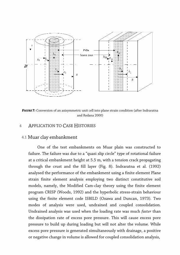
FIGURE 7: Conversion of an axisymmetric unit cell into plane strain condition (after Indraratna and Redana 2000)
4 APPLICATION TO CASE HISTORIES
4.1 Muar clay embankment
One of the test embankments on Muar plain was constructed to
failure. The failure was due to a “quasi slip circle” type of rotational failure
at a critical embankment height at 5.5 m, with a tension crack propagating
through the crust and the fill layer (Fig. 8). Indraratna et al. (1992)
analysed the performance of the embankment using a finite element Plane
strain finite element analysis employing two distinct constitutive soil
models, namely, the Modified Cam-clay theory using the finite element
program CRISP (Woods, 1992) and the hyperbolic stress-strain behaviour
using the finite element code ISBILD (Ozawa and Duncan, 1973). Two
modes of analysis were used, undrained and coupled consolidation.
Undrained analysis was used when the loading rate was much faster than
the dissipation rate of excess pore pressure. This will cause excess pore
pressure to build up during loading but will not alter the volume. While
excess pore pressure is generated simultaneously with drainage, a positive
or negative change in volume is allowed for coupled consolidation analysis,
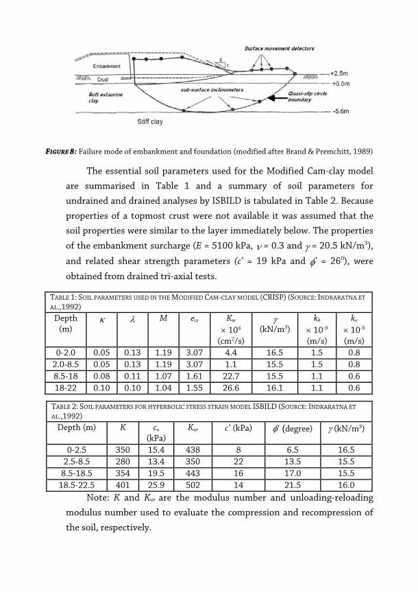
FIGURE 8: Failure mode of embankment and foundation (modified after Brand & Premchitt, 1989)
The essential soil parameters used for the Modified Cam-clay model
are summarised in Table 1 and a summary of soil parameters for
undrained and drained analyses by ISBILD is tabulated in Table 2. Because
properties of a topmost crust were not available it was assumed that the
soil properties were similar to the layer immediately below. The properties
of the embankment surcharge (E = 5100 kPa, ν = 0.3 and γ = 20.5 kN/m3),
and related shear strength parameters (c’ = 19 kPa and φ’ = 260), were
obtained from drained tri-axial tests.
TABLE 1: SOIL PARAMETERS USED IN THE MODIFIED CAM-CLAY MODEL (CRISP) (SOURCE: INDRARATNA ET
AL.,1992) Depth
(m) κ λ M ecs Kw
× 104
(cm2/s)
γ (kN/m3)
kh × 10-9 (m/s)
kv
× 10-9 (m/s)
0-2.0 0.05 0.13 1.19 3.07 4.4 16.5 1.5 0.8 2.0-8.5 0.05 0.13 1.19 3.07 1.1 15.5 1.5 0.8 8.5-18 0.08 0.11 1.07 1.61 22.7 15.5 1.1 0.6 18-22 0.10 0.10 1.04 1.55 26.6 16.1 1.1 0.6
TABLE 2: SOIL PARAMETERS FOR HYPERBOLIC STRESS STRAIN MODEL ISBILD (SOURCE: INDRARATNA ET
AL.,1992) Depth (m) K cu
(kPa) Kur c’ (kPa) φ’ (degree) γ (kN/m3)
0-2.5 350 15.4 438 8 6.5 16.5 2.5-8.5 280 13.4 350 22 13.5 15.5
8.5-18.5 354 19.5 443 16 17.0 15.5 18.5-22.5 401 25.9 502 14 21.5 16.0
Note: K and Kur are the modulus number and unloading-reloading
modulus number used to evaluate the compression and recompression of
the soil, respectively.
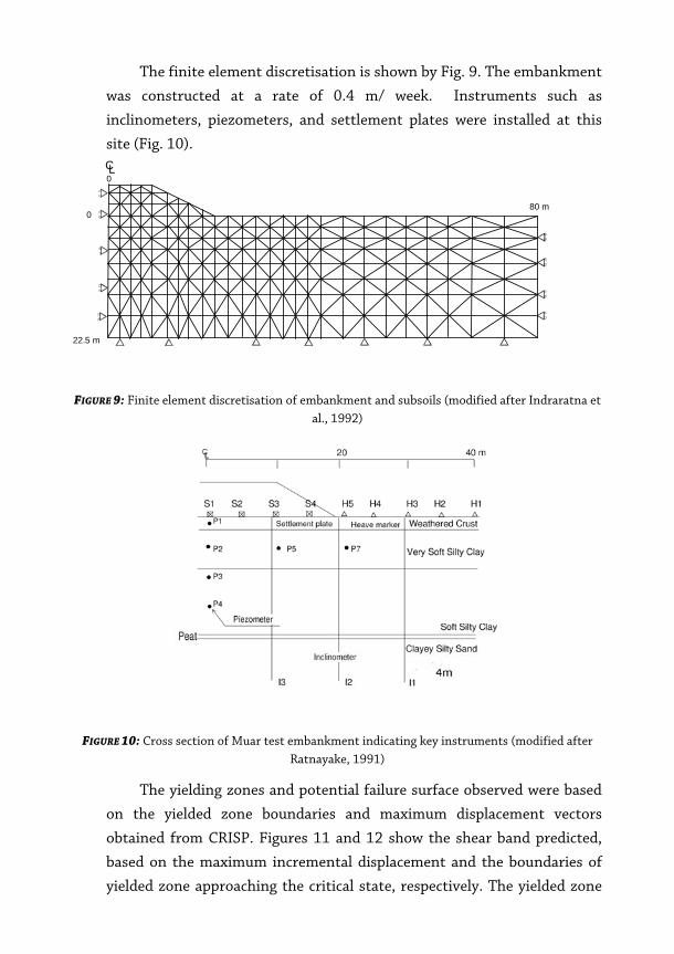
The finite element discretisation is shown by Fig. 9. The embankment
was constructed at a rate of 0.4 m/ week. Instruments such as
inclinometers, piezometers, and settlement plates were installed at this
site (Fig. 10).
CL0
80 m
22.5 m
0
FIGURE 9: Finite element discretisation of embankment and subsoils (modified after Indraratna et al., 1992)
FIGURE 10: Cross section of Muar test embankment indicating key instruments (modified after Ratnayake, 1991)
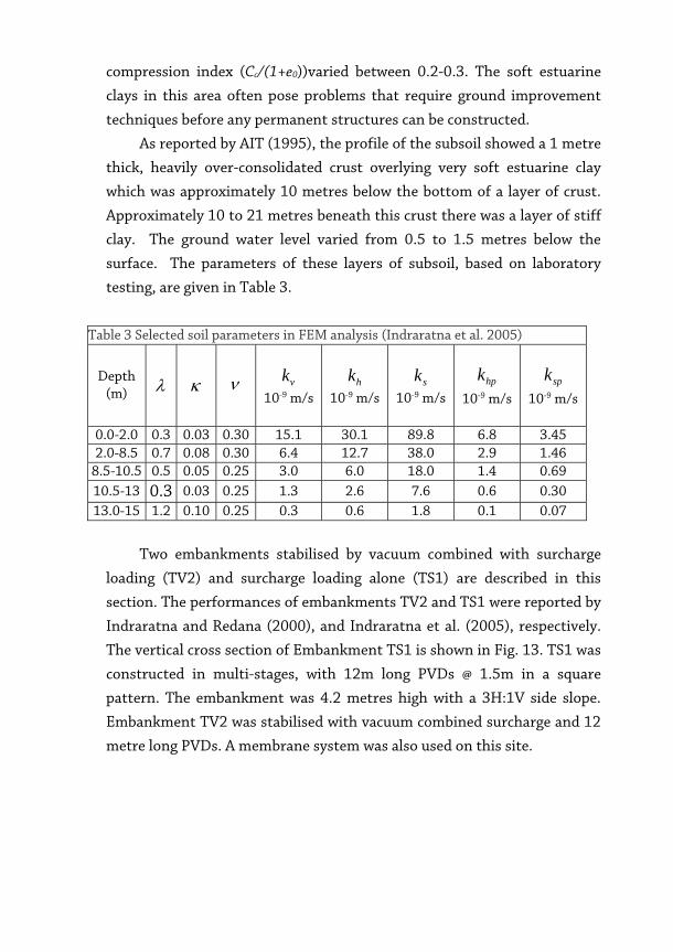
The yielding zones and potential failure surface observed were based
on the yielded zone boundaries and maximum displacement vectors
obtained from CRISP. Figures 11 and 12 show the shear band predicted,
based on the maximum incremental displacement and the boundaries of
yielded zone approaching the critical state, respectively. The yielded zone
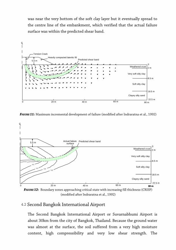
was near the very bottom of the soft clay layer but it eventually spread to
the centre line of the embankment, which verified that the actual failure
surface was within the predicted shear band.
CL
Tension CrackHeavily compacted lateritic fill
Predicted shear band
02 m
8.5 m
18.5 m
22.5 m80 m60 m40 m0 20 m
Weathered crust
Very soft silty clay
Soft silty clay
Clayey silty sand
5.5 m
FIGURE 11: Maximum incremental development of failure (modified after Indraratna et al., 1992)
CL
Actual failure surface
Predicted shear band
02 m
8.5 m
18.5 m
22.5 m80 m60 m40 m0 20 m
5.5 m
1.5
4.0
4.5 5.05.5
80 m
Weathered crust
Very soft silty clay
Soft silty clay
Clayey silty sand
FIGURE 12: Boundary zones approaching critical state with increasing fill thickness (CRISP) (modified after Indraratna et al., 1992)
4.2 Second Bangkok International Airport
The Second Bangkok International Airport or Suvarnabhumi Airport is
about 30km from the city of Bangkok, Thailand. Because the ground water
was almost at the surface, the soil suffered from a very high moisture
content, high compressibility and very low shear strength. The
compression index (Cc/(1+e0))varied between 0.2-0.3. The soft estuarine
clays in this area often pose problems that require ground improvement
techniques before any permanent structures can be constructed.
As reported by AIT (1995), the profile of the subsoil showed a 1 metre
thick, heavily over-consolidated crust overlying very soft estuarine clay
which was approximately 10 metres below the bottom of a layer of crust.
Approximately 10 to 21 metres beneath this crust there was a layer of stiff
clay. The ground water level varied from 0.5 to 1.5 metres below the
surface. The parameters of these layers of subsoil, based on laboratory
testing, are given in Table 3.
Table 3 Selected soil parameters in FEM analysis (Indraratna et al. 2005)
Depth (m) λ κ ν vk
10-9 m/s hk
10-9 m/s sk
10-9 m/s hpk
10-9 m/s spk
10-9 m/s
0.0-2.0 0.3 0.03 0.30 15.1 30.1 89.8 6.8 3.45 2.0-8.5 0.7 0.08 0.30 6.4 12.7 38.0 2.9 1.46
8.5-10.5 0.5 0.05 0.25 3.0 6.0 18.0 1.4 0.69 10.5-13 0.3 0.03 0.25 1.3 2.6 7.6 0.6 0.30 13.0-15 1.2 0.10 0.25 0.3 0.6 1.8 0.1 0.07
Two embankments stabilised by vacuum combined with surcharge
loading (TV2) and surcharge loading alone (TS1) are described in this
section. The performances of embankments TV2 and TS1 were reported by
Indraratna and Redana (2000), and Indraratna et al. (2005), respectively.
The vertical cross section of Embankment TS1 is shown in Fig. 13. TS1 was
constructed in multi-stages, with 12m long PVDs @ 1.5m in a square
pattern. The embankment was 4.2 metres high with a 3H:1V side slope.
Embankment TV2 was stabilised with vacuum combined surcharge and 12
metre long PVDs. A membrane system was also used on this site.
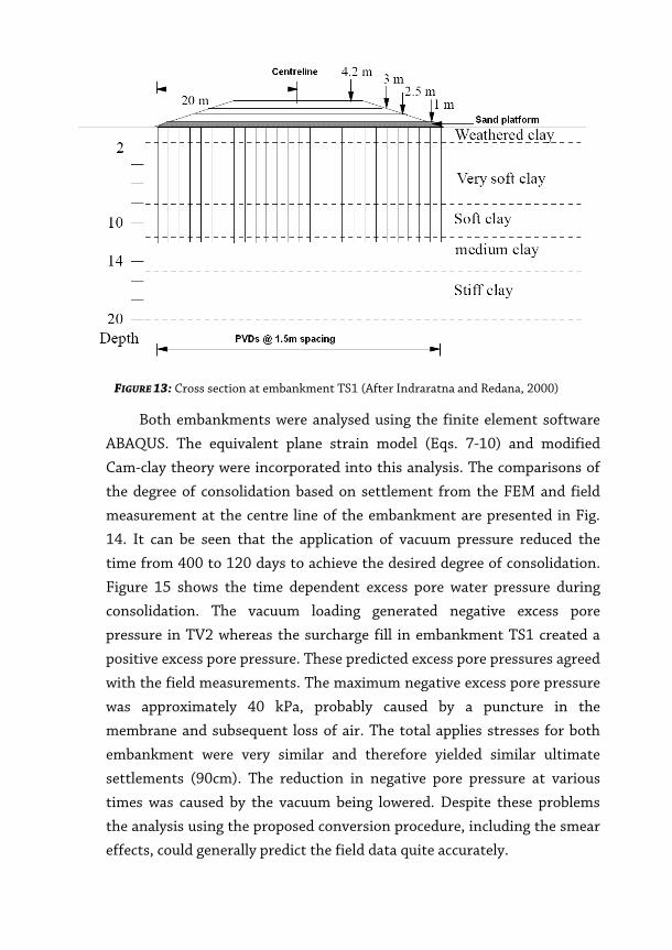
FIGURE 13: Cross section at embankment TS1 (After Indraratna and Redana, 2000)
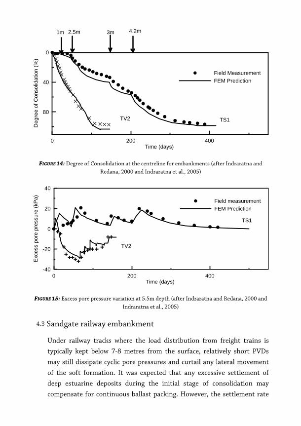
Both embankments were analysed using the finite element software
ABAQUS. The equivalent plane strain model (Eqs. 7-10) and modified
Cam-clay theory were incorporated into this analysis. The comparisons of
the degree of consolidation based on settlement from the FEM and field
measurement at the centre line of the embankment are presented in Fig.
14. It can be seen that the application of vacuum pressure reduced the
time from 400 to 120 days to achieve the desired degree of consolidation.
Figure 15 shows the time dependent excess pore water pressure during
consolidation. The vacuum loading generated negative excess pore
pressure in TV2 whereas the surcharge fill in embankment TS1 created a
positive excess pore pressure. These predicted excess pore pressures agreed
with the field measurements. The maximum negative excess pore pressure
was approximately 40 kPa, probably caused by a puncture in the
membrane and subsequent loss of air. The total applies stresses for both
embankment were very similar and therefore yielded similar ultimate
settlements (90cm). The reduction in negative pore pressure at various
times was caused by the vacuum being lowered. Despite these problems
the analysis using the proposed conversion procedure, including the smear
effects, could generally predict the field data quite accurately.
0 200 400Time (days)
80
40
0
Deg
ree
of C
onso
lidat
ion
(%)
Field MeasurementFEM Prediction
TS1TV2
1m 2.5m 3m 4.2m
FIGURE 14: Degree of Consolidation at the centreline for embankments (after Indraratna and Redana, 2000 and Indraratna et al., 2005)
0 200 400Time (days)
-40
-20
0
20
40
Exc
ess
pore
pre
ssur
e (k
Pa) Field measurement
FEM Prediction
TS1
TV2
FIGURE 15: Excess pore pressure variation at 5.5m depth (after Indraratna and Redana, 2000 and Indraratna et al., 2005)
4.3 Sandgate railway embankment
Under railway tracks where the load distribution from freight trains is
typically kept below 7-8 metres from the surface, relatively short PVDs
may still dissipate cyclic pore pressures and curtail any lateral movement
of the soft formation. It was expected that any excessive settlement of
deep estuarine deposits during the initial stage of consolidation may
compensate for continuous ballast packing. However, the settlement rate
can still be controlled by optimising the spacing and pattern of drain
installation. In this section a case history where short PVDs were installed
beneath a rail track built on soft formation is presented with the finite
element analysis (Indraratna et al. 2009). The finite element analysis used
by the Authors to design the track was a typical Class A prediction for a
field observation because it was made before it was constructed.
To improve the conditions for rail traffic entering Sandgate,
Kooragang Island, Australia, where major coal mining sites are located, two
new railway lines were needed close to the existing track. An in-situ and
laboratory test was undertaken by GHD Longmac (Chan, 2005) to obtain
the essential soil parameters. This investigation included boreholes,
piezocone tests, in-situ vane shear tests, test pits, and laboratory tests that
included testing the soil index property, standard oedometer testing, and
vane shear testing.
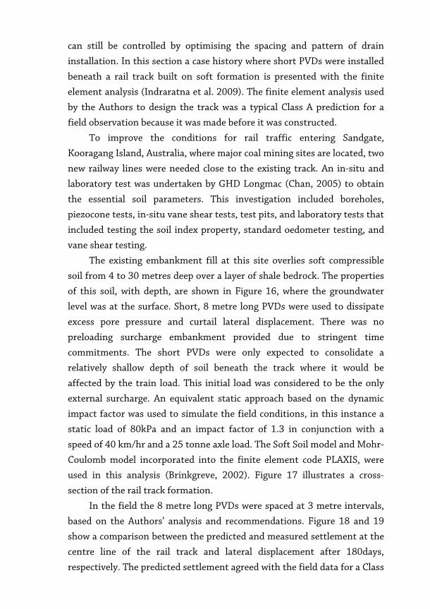
The existing embankment fill at this site overlies soft compressible
soil from 4 to 30 metres deep over a layer of shale bedrock. The properties
of this soil, with depth, are shown in Figure 16, where the groundwater
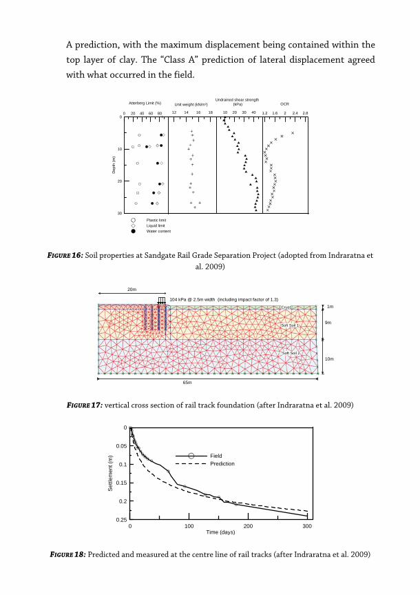
level was at the surface. Short, 8 metre long PVDs were used to dissipate
excess pore pressure and curtail lateral displacement. There was no
preloading surcharge embankment provided due to stringent time
commitments. The short PVDs were only expected to consolidate a
relatively shallow depth of soil beneath the track where it would be
affected by the train load. This initial load was considered to be the only
external surcharge. An equivalent static approach based on the dynamic
impact factor was used to simulate the field conditions, in this instance a
static load of 80kPa and an impact factor of 1.3 in conjunction with a
speed of 40 km/hr and a 25 tonne axle load. The Soft Soil model and Mohr-
Coulomb model incorporated into the finite element code PLAXIS, were
used in this analysis (Brinkgreve, 2002). Figure 17 illustrates a cross-
section of the rail track formation.
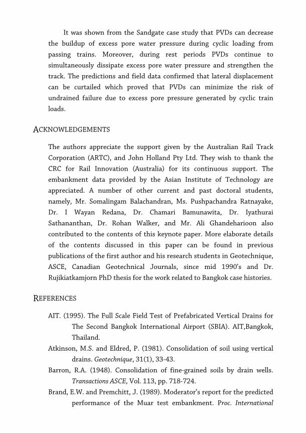
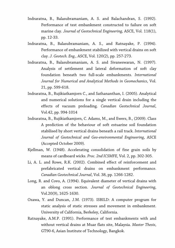
In the field the 8 metre long PVDs were spaced at 3 metre intervals,
based on the Authors’ analysis and recommendations. Figure 18 and 19
show a comparison between the predicted and measured settlement at the
centre line of the rail track and lateral displacement after 180days,
respectively. The predicted settlement agreed with the field data for a Class
A prediction, with the maximum displacement being contained within the
top layer of clay. The “Class A” prediction of lateral displacement agreed
with what occurred in the field.
0 20 40 60 80
Atterberg Limit (%)
30
20
10
0D
epth
(m)
12 14 16 18
Unit weight (kN/m3)
10 20 30 40
Undrained shear strength (kPa)
1.2 1.6 2 2.4 2.8
OCR
Plastic limitLiquid limitWater content
FIGURE 16: Soil properties at Sandgate Rail Grade Separation Project (adopted from Indraratna et al. 2009)
104 kPa @ 2.5m width (including impact factor of 1.3)
20m
65m
1m
9m
10m
Crust
Soft Soil 1
Soft Soil 2
FIGURE 17: vertical cross section of rail track foundation (after Indraratna et al. 2009)
0 100 200 300Time (days)
0.25
0.2
0.15
0.1
0.05
0
Set
tlem
ent (
m) Field
Prediction
FIGURE 18: Predicted and measured at the centre line of rail tracks (after Indraratna et al. 2009)

0 10 20 30 40Lateral displacement (mm)
-20
-16
-12
-8
-4
0
Dep
th (m
)
FieldPrediction
FIGURE 19: Measured and predicted lateral displacement profiles near the rail embankment toe at 180 days (after Indraratna et al. 2009)
5 CONCLUSION
Various types of vertical drains have been used to accelerate the rate of
primary consolidation. A comparison between embankments stabilised
with a vacuum combined with a surcharge, and a surcharge alone, were
analysed and discussed. Consolidation time with a vacuum applied was
substantially reduced and lateral displacement curtailed, and if sufficient
vacuum pressure is sustained, the thickness of the surcharge fill required
may be reduced by several metres.
A plane strain finite element analysis with an appropriate conversion
procedure is often enough to obtain an accurate prediction for large
construction sites. An equivalent plane strain solution was used for
selected case histories to demonstrate its ability to predict realistic
behaviour. There is no doubt that a system of vacuum consolidation via
PVDs is a useful and practical approach for accelerating radial
consolidation because it eliminates the need for a large amount of good
quality surcharge material, via air leak protection in the field. Accurate
modelling of vacuum preloading requires both laboratory and field studies
to quantify the nature of its distribution within a given formation and
drainage system.
It was shown from the Sandgate case study that PVDs can decrease
the buildup of excess pore water pressure during cyclic loading from
passing trains. Moreover, during rest periods PVDs continue to
simultaneously dissipate excess pore water pressure and strengthen the
track. The predictions and field data confirmed that lateral displacement
can be curtailed which proved that PVDs can minimize the risk of
undrained failure due to excess pore pressure generated by cyclic train
loads.
ACKNOWLEDGEMENTS
The authors appreciate the support given by the Australian Rail Track
Corporation (ARTC), and John Holland Pty Ltd. They wish to thank the
CRC for Rail Innovation (Australia) for its continuous support. The
embankment data provided by the Asian Institute of Technology are
appreciated. A number of other current and past doctoral students,
namely, Mr. Somalingam Balachandran, Ms. Pushpachandra Ratnayake,
Dr. I Wayan Redana, Dr. Chamari Bamunawita, Dr. Iyathurai
Sathananthan, Dr. Rohan Walker, and Mr. Ali Ghandeharioon also
contributed to the contents of this keynote paper. More elaborate details
of the contents discussed in this paper can be found in previous
publications of the first author and his research students in Geotechnique,
ASCE, Canadian Geotechnical Journals, since mid 1990’s and Dr.
Rujikiatkamjorn PhD thesis for the work related to Bangkok case histories.
REFERENCES
AIT. (1995). The Full Scale Field Test of Prefabricated Vertical Drains for
The Second Bangkok International Airport (SBIA). AIT,Bangkok,
Thailand.
Atkinson, M.S. and Eldred, P. (1981). Consolidation of soil using vertical
drains. Geotechnique, 31(1), 33-43.
Barron, R.A. (1948). Consolidation of fine-grained soils by drain wells.
Transactions ASCE, Vol. 113, pp. 718-724.
Brand, E.W. and Premchitt, J. (1989). Moderator’s report for the predicted
performance of the Muar test embankment. Proc. International

Symposium on Trial Embankment on Malysian Marine Clays, Kuala
Lumpur, Malaysia, Vol. 2, pp. 1/32-1/49.
Brinkgreve, R.B.J. (2002). PLAXIS (Version 8) User’s Manual. Delft
University of Technology and PLAXIS B.V., Netherlands.
Cao, L. F., Teh, C. I., and Chang, M. F. (2001). Undrained Cavity Expansion
in Modified Cam Clay I: Theoretical Analysis." Geotechnique, Vol.
51(4); pp. 323-334.
Chan, K. (2005). Geotechnical information report for the Sandgate Rail
Grade Separation, Hunter Valley Region, Australia.
Cognon, J.M., Juran, I. and Thevanayagam, S. (1994). Vacuum
consolidation technology-principles and field experience. Proc.
Conference on Foundations and Embankments Deformations, College
Station, Texas, Vol. 2, pp.1237-1248.
Ghandeharioon, A., Indraratna, B., and Rujikiatkamjorn, C. (2009).
Analysis of soil disturbance associated with mandrel-driven
prefabricated vertical drains using an elliptical cavity expansion
theory. International Journal of Geomechanics, ASCE. (Accepted,
August 2009).
Hansbo, S., (1979). Conslidation of clay by band-shaped prefabricated
drains. Ground Eng., 12(5), 16-25.
Hansbo, S. (1981). Consolidation of fine-grained soils by prefabricated
drains. In Proceedings of 10th International Conference on Soil
Mechanics and Foundation Engineering, Stockholm, Balkema,
Rotterdam, 3, pp. 677-682.
Hird, C.C., Pyrah, I.C., and Russell, D. (1992). Finite element modelling of
vertical drains beneath embankments on soft ground.
Geotechnique, Vol. 42(3), pp. 499-511.
Holtz, R. D. (1987). Preloading with prefabricated vertical strip drains,
Geotextiles and Geomembranes, Vol. 6 (1–3), pp. 109–131.
Indraratna, B., and Redana, I. W. (2000). Numerical modeling of vertical
drains with smear and well resistance installed in soft clay.
Canadian Geotechnical Journal, Vol. 37, pp. 132-145.
Indraratna, B., Bamunawita, C., and Khabbaz, H. 2004. Numerical
modeling of vacuum preloading and field applications. Canadian
Geotechnical Journal, Vol. 41, pp. 1098-1110.
Indraratna, B., Balasubramaniam, A. S. and Balachandran, S. (1992).
Performance of test embankment constructed to failure on soft
marine clay. Journal of Geotechnical Engineering, ASCE, Vol. 118(1),
pp. 12-33.
Indraratna, B., Balasubramaniam, A. S., and Ratnayake, P. (1994).
Performance of embankment stabilized with vertical drains on soft
clay. J. Geotech. Eng., ASCE, Vol. 120(2), pp. 257-273.
Indraratna, B., Balasubramaniam, A. S. and Sivaneswaran, N. (1997).
Analysis of settlement and lateral deformation of soft clay
foundation beneath two full-scale embankments. International
Journal for Numerical and Analytical Methods in Geomechanics, Vol.
21, pp. 599-618.
Indraratna, B., Rujikiatkamjorn C., and Sathananthan, I. (2005). Analytical
and numerical solutions for a single vertical drain including the
effects of vacuum preloading. Canadian Geotechnical Journal,
Vol.42, pp. 994-1014
Indraratna, B., Rujikiatkamjorn, C. Adams, M., and Ewers, B., (2009). Class
A prediction of the behaviour of soft estuarine soil foundation
stabilised by short vertical drains beneath a rail track. International
Journal of Geotechnical and Geo-environmental Engineering, ASCE
(Accepted October 2009).
Kjellman, W. (1948). Accelerating consolidation of fine grain soils by
means of cardboard wicks. Proc. 2nd ICSMFE, Vol. 2, pp. 302-305.
Li, A. L. and Rowe, R.K. (2002). Combined effect of reinforcement and
prefabricated vertical drains on embankment performance.
Canadian Geotechnical Journal, Vol. 38, pp. 1266-1282.
Long, R. and Covo, A. (1994). Equivalent diameter of vertical drains with
an oblong cross section. Journal of Geotechnical Engineering,
Vol.20(9), 1625-1630.
Ozawa, Y. and Duncan, J.M. (1973). ISBILD: A computer program for
static analysis of static stresses and movement in embankment.
University of California, Berkeley, California.
Ratnayake, A.M.P. (1991). Performance of test embankments with and
without vertical drains at Muar flats site, Malaysia. Master Thesis,
GT90-6, Asian Institute of Technology, Bangkok.

Sathananthan, I. and Indraratna, B. (2006). Laboratory Evaluation of
Smear Zone and Correlation between Permeability and Moisture
Content, J. of Geotechnical & Geoenvironmental Engineering, ASCE,
Vol. 132(7), pp. 942-945.
Sathananthan, I., Indraratna, B., and Rujikiatkamjorn C., (2008). The
evaluation of smear zone extent surrounding mandrel driven
vertical drains using the cavity expansion theory. International
Journal of Geomechanics, ASCE. Vol. 8(6), 355-365.
Woods, R. (1992). SAGE CRISP technical reference manual. The CRISP
Consortium Ltd. UK.
Yoshikuni, H. and Nakanodo, H. (1974). Consolidation of fine-grained
soils by drain wells with finite permeability. Japanese Society Soil
Mechanics and Foundation Engineering, Vol. 14(2), pp. 35-46.