smoke control by pressurisation - trang...
TRANSCRIPT
FLÄKT WOODS LIMITED
FANS IN FIRE SAFETY
SMOKE CONTROLBY
PRESSURISATION
By: J.A. WILD, C.ENG; F.I.MECH.E.
November 1998(Third Edition)
© Copyright 2000 Fläkt Woods Limted England.

2
3
CONTENTS
PAGE NO:
Summary 4
Chapter One Smoke Control By Pressurisation - Basics 5 - 6
Chapter Two Why Pressurisation? 7 - 8
Chapter Three The Pressurisation System 9 - 16
Chapter Four Air Requirements of a Pressurisation System 17- 20
Chapter Five Fan Selections 21- 27
Chapter Six Fans for Pressurisation Systems 28 - 29
Appendix One References 30
ACKNOWLEDGEMENTS
The author wishes to acknowledge the assistance he received from Mr Cyril Moss,KG Smoke Dispersals Ltd and Mr E Gorden Butcher of Fire Check Consultants withthe preparation of this paper.
4
WOODS AIR MOVEMENT LIMITED
Fans for Pressurisation Systems
By: J.A. WILD, C.ENG; F.I.MECH.E.
SUMMARY
There are basically two main methods for controlling smoke in buildings to
prevent it contaminating escape routes - by Ventilation and by Pressurisation.
Fans for Fire Smoke Venting (Ref 1) examines the motivation behind the
increased use of Powered Ventilators for the exhausting of hot smoke from
fires and determines their requirements and specifications.
This paper undertakes a similar task to determine the requirements and
specification for FANS IN PRESSURISATION SYSTEMS, based on the
requirements of BS5588 Part4:1998.
5
CHAPTER 1
Smoke Control By Pressurisation - Basics
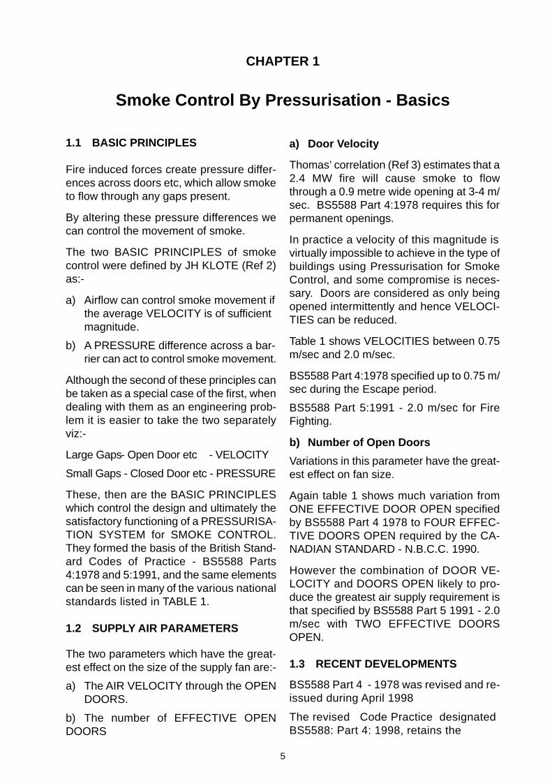
1.1 BASIC PRINCIPLES
Fire induced forces create pressure differ-ences across doors etc, which allow smoketo flow through any gaps present.
By altering these pressure differences wecan control the movement of smoke.
The two BASIC PRINCIPLES of smokecontrol were defined by JH KLOTE (Ref 2)as:-
a) Airflow can control smoke movement ifthe average VELOCITY is of sufficientmagnitude.
b) A PRESSURE difference across a bar-rier can act to control smoke movement.
Although the second of these principles canbe taken as a special case of the first, whendealing with them as an engineering prob-lem it is easier to take the two separatelyviz:-
Large Gaps - Open Door etc - VELOCITY
Small Gaps - Closed Door etc - PRESSURE
These, then are the BASIC PRINCIPLESwhich control the design and ultimately thesatisfactory functioning of a PRESSURISA-TION SYSTEM for SMOKE CONTROL.They formed the basis of the British Stand-ard Codes of Practice - BS5588 Parts4:1978 and 5:1991, and the same elementscan be seen in many of the various nationalstandards listed in TABLE 1.
1.2 SUPPLY AIR PARAMETERS
The two parameters which have the great-est effect on the size of the supply fan are:-
a) The AIR VELOCITY through the OPENDOORS.
b) The number of EFFECTIVE OPENDOORS
a) Door Velocity
Thomas’ correlation (Ref 3) estimates that a2.4 MW fire will cause smoke to flowthrough a 0.9 metre wide opening at 3-4 m/sec. BS5588 Part 4:1978 requires this forpermanent openings.
In practice a velocity of this magnitude isvirtually impossible to achieve in the type ofbuildings using Pressurisation for SmokeControl, and some compromise is neces-sary. Doors are considered as only beingopened intermittently and hence VELOCI-TIES can be reduced.
Table 1 shows VELOCITIES between 0.75m/sec and 2.0 m/sec.
BS5588 Part 4:1978 specified up to 0.75 m/sec during the Escape period.
BS5588 Part 5:1991 - 2.0 m/sec for FireFighting.
b) Number of Open Doors
Variations in this parameter have the great-est effect on fan size.
Again table 1 shows much variation fromONE EFFECTIVE DOOR OPEN specifiedby BS5588 Part 4 1978 to FOUR EFFEC-TIVE DOORS OPEN required by the CA-NADIAN STANDARD - N.B.C.C. 1990.
However the combination of DOOR VE-LOCITY and DOORS OPEN likely to pro-duce the greatest air supply requirement isthat specified by BS5588 Part 5 1991 - 2.0m/sec with TWO EFFECTIVE DOORSOPEN.
1.3 RECENT DEVELOPMENTS
BS5588 Part 4 - 1978 was revised and re-issued during April 1998
The revised Code Practice designatedBS5588: Part 4: 1998, retains the
6
0.75m/sec air velocity through the open
door(s) onto the fire floor during the escape
phase, but now demands that up to three
effective doors be regarded as being
OPEN when calculating the supply air quan-
tity required. The number of open doors
varies with the type and usage of the build-
ing, but in general, this change from 1978
code will increase the quantity of supply air
required.
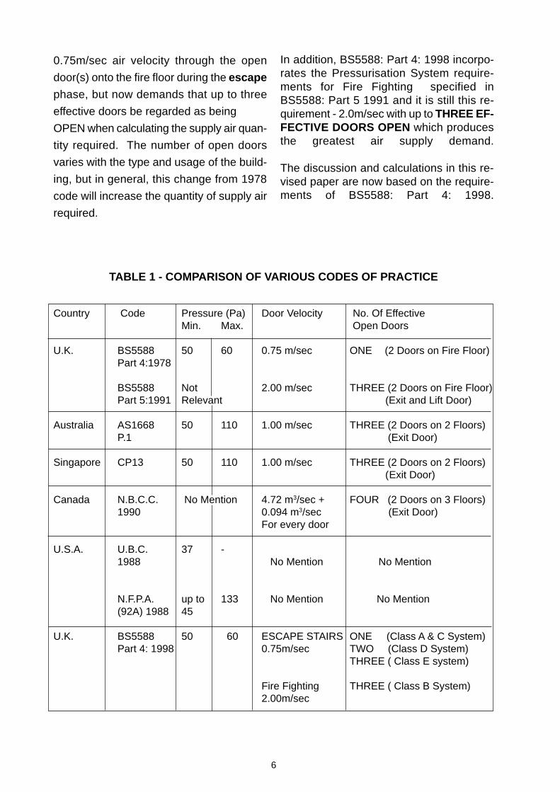
TABLE 1 - COMPARISON OF VARIOUS CODES OF PRACTICE
Country Code Pressure (Pa) Door Velocity No. Of EffectiveMin. Max. Open Doors
U.K. BS5588 50 60 0.75 m/sec ONE (2 Doors on Fire Floor)Part 4:1978
BS5588 Not 2.00 m/sec THREE (2 Doors on Fire Floor)Part 5:1991 Relevant (Exit and Lift Door)
Australia AS1668 50 110 1.00 m/sec THREE (2 Doors on 2 Floors)P.1 (Exit Door)
Singapore CP13 50 110 1.00 m/sec THREE (2 Doors on 2 Floors) (Exit Door)
Canada N.B.C.C. No Mention 4.72 m3/sec + FOUR (2 Doors on 3 Floors)1990 0.094 m3/sec (Exit Door)
For every door
U.S.A. U.B.C. 37 -1988 No Mention No Mention
N.F.P.A. up to 133 No Mention No Mention(92A) 1988 45
U.K. BS5588 50 60 ESCAPE STAIRS ONE (Class A & C System)Part 4: 1998 0.75m/sec TWO (Class D System)
THREE ( Class E system)
Fire Fighting THREE ( Class B System)2.00m/sec
In addition, BS5588: Part 4: 1998 incorpo-rates the Pressurisation System require-ments for Fire Fighting specified inBS5588: Part 5 1991 and it is still this re-quirement - 2.0m/sec with up to THREE EF-FECTIVE DOORS OPEN which producesthe greatest air supply demand.
The discussion and calculations in this re-vised paper are now based on the require-ments of BS5588: Part 4: 1998.
7
2.1 OBJECTIVE OF SMOKE CONTROL
The objective of any SMOKE CONTROLsystem is to keep the smoke and toxicgases out of the escape route long enoughto allow the occupants to escape or seek asafe refuge. In addition an adequate smokecontrol system will help the fire fighters dealboth with the fire and any residue smoke.
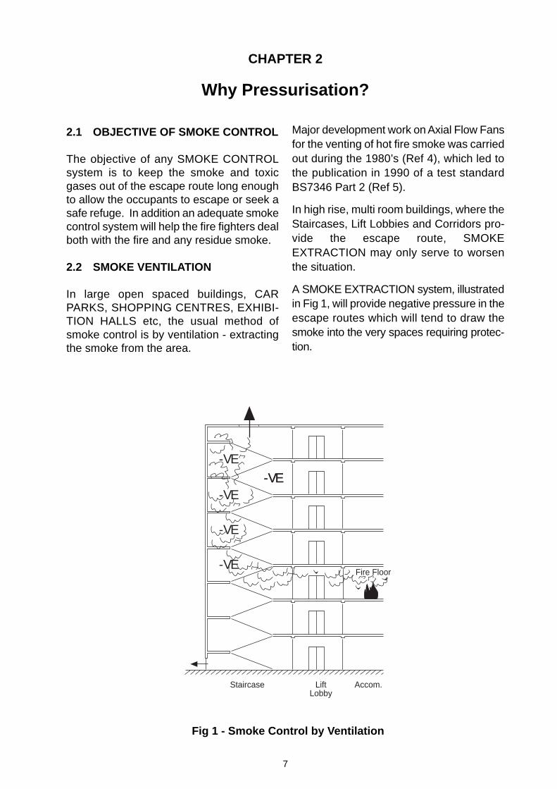
2.2 SMOKE VENTILATION
In large open spaced buildings, CARPARKS, SHOPPING CENTRES, EXHIBI-TION HALLS etc, the usual method ofsmoke control is by ventilation - extractingthe smoke from the area.
Major development work on Axial Flow Fansfor the venting of hot fire smoke was carriedout during the 1980’s (Ref 4), which led tothe publication in 1990 of a test standardBS7346 Part 2 (Ref 5).
In high rise, multi room buildings, where theStaircases, Lift Lobbies and Corridors pro-vide the escape route, SMOKEEXTRACTION may only serve to worsenthe situation.
A SMOKE EXTRACTION system, illustratedin Fig 1, will provide negative pressure in theescape routes which will tend to draw thesmoke into the very spaces requiring protec-tion.
CHAPTER 2
Why Pressurisation?
Fig 1 - Smoke Control by Ventilation
Staircase LiftLobby
Accom.
Fire Floor
-VE-VE-VE
-VE
-VE
-VE
8
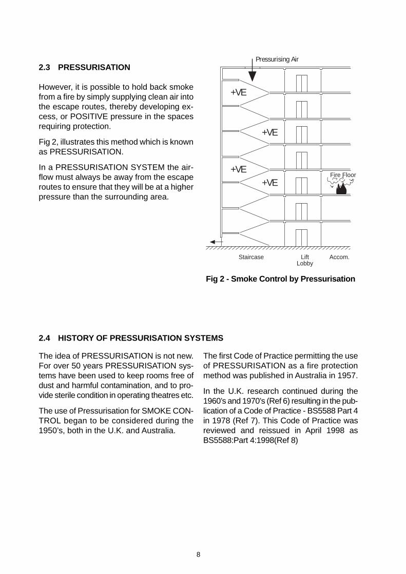
2.3 PRESSURISATION
However, it is possible to hold back smokefrom a fire by simply supplying clean air intothe escape routes, thereby developing ex-cess, or POSITIVE pressure in the spacesrequiring protection.
Fig 2, illustrates this method which is knownas PRESSURISATION.
In a PRESSURISATION SYSTEM the air-flow must always be away from the escaperoutes to ensure that they will be at a higherpressure than the surrounding area.
Fig 2 - Smoke Control by Pressurisation
Staircase LiftLobby
Accom.
Fire Floor
+VE
+VE
+VE+VE
Pressurising Air
The idea of PRESSURISATION is not new.For over 50 years PRESSURISATION sys-tems have been used to keep rooms free ofdust and harmful contamination, and to pro-vide sterile condition in operating theatres etc.
The use of Pressurisation for SMOKE CON-TROL began to be considered during the1950’s, both in the U.K. and Australia.
2.4 HISTORY OF PRESSURISATION SYSTEMS
The first Code of Practice permitting the useof PRESSURISATION as a fire protectionmethod was published in Australia in 1957.
In the U.K. research continued during the1960’s and 1970’s (Ref 6) resulting in the pub-lication of a Code of Practice - BS5588 Part 4in 1978 (Ref 7). This Code of Practice wasreviewed and reissued in April 1998 asBS5588:Part 4:1998(Ref 8)
9
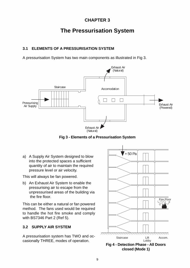
3.1 ELEMENTS OF A PRESSURISATION SYSTEM
A pressurisation System has two main components as illustrated in Fig 3.
CHAPTER 3
The Pressurisation System
PressurisingAir Supply
Staircase
Exhaust Air(Natural)
Exhaust Air(Powered)
Exhaust Air(Natural)
Accomodation
Fig 3 - Elements of a Pressurisation System
a) A Supply Air System designed to blowinto the protected spaces a sufficientquantity of air to maintain the requiredpressure level or air velocity.
This will always be fan powered.
b) An Exhaust Air System to enable thepressurising air to escape from theunpressurised areas of the building via the fire floor.
This can be either a natural or fan poweredmethod. The fans used would be requiredto handle the hot fire smoke and complywith BS7346 Part 2 (Ref 5).
3.2 SUPPLY AIR SYSTEM
A pressurisation system has TWO and oc-casionally THREE, modes of operation.
Fig 4 - Detection Phase - All Doorsclosed (Mode 1)
Staircase LiftLobby
Accom.
Fire Floor
+ 50 Pa
10
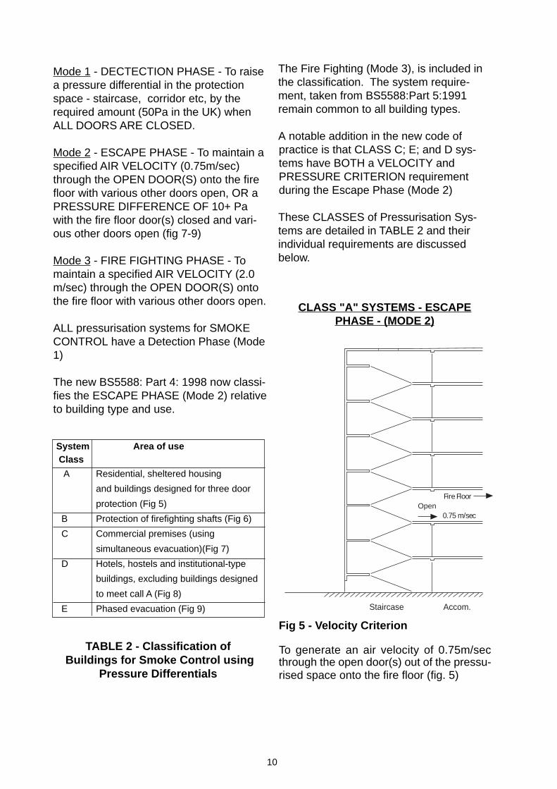
CLASS "A" SYSTEMS - ESCAPEPHASE - (MODE 2)
TABLE 2 - Classification of Buildings for Smoke Control using
Pressure Differentials
Mode 1 - DECTECTION PHASE - To raisea pressure differential in the protectionspace - staircase, corridor etc, by therequired amount (50Pa in the UK) whenALL DOORS ARE CLOSED.
Mode 2 - ESCAPE PHASE - To maintain aspecified AIR VELOCITY (0.75m/sec)through the OPEN DOOR(S) onto the firefloor with various other doors open, OR aPRESSURE DIFFERENCE OF 10+ Pawith the fire floor door(s) closed and vari-ous other doors open (fig 7-9)
Mode 3 - FIRE FIGHTING PHASE - Tomaintain a specified AIR VELOCITY (2.0m/sec) through the OPEN DOOR(S) ontothe fire floor with various other doors open.
ALL pressurisation systems for SMOKECONTROL have a Detection Phase (Mode1)
The new BS5588: Part 4: 1998 now classi-fies the ESCAPE PHASE (Mode 2) relativeto building type and use.
The Fire Fighting (Mode 3), is included inthe classification. The system require-ment, taken from BS5588:Part 5:1991remain common to all building types.
A notable addition in the new code ofpractice is that CLASS C; E; and D sys-tems have BOTH a VELOCITY andPRESSURE CRITERION requirementduring the Escape Phase (Mode 2)
These CLASSES of Pressurisation Sys-tems are detailed in TABLE 2 and theirindividual requirements are discussedbelow.
Fig 5 - Velocity Criterion
To generate an air velocity of 0.75m/secthrough the open door(s) out of the pressu-rised space onto the fire floor (fig. 5)
System Area of use Class
A Residential, sheltered housing
and buildings designed for three door
protection (Fig 5)
B Protection of firefighting shafts (Fig 6)
C Commercial premises (using
simultaneous evacuation)(Fig 7)
D Hotels, hostels and institutional-type
buildings, excluding buildings designed
to meet call A (Fig 8)
E Phased evacuation (Fig 9) Staircase Accom.
Fire FloorOpen
0.75 m/sec
11
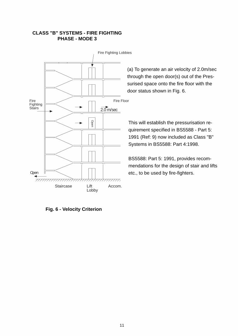
Fig. 6 - Velocity Criterion
(a) To generate an air velocity of 2.0m/sec
through the open door(s) out of the Pres-
surised space onto the fire floor with the
door status shown in Fig. 6.
This will establish the pressurisation re-
quirement specified in BS5588 - Part 5:
1991 (Ref: 9) now included as Class "B"
Systems in BS5588: Part 4:1998.
BS5588: Part 5: 1991, provides recom-
mendations for the design of stair and lifts
etc., to be used by fire-fighters.
CLASS "B" SYSTEMS - FIRE FIGHTINGPHASE - MODE 3
Staircase LiftLobby
Accom.
2.0 m/sec
Open
FireFightingStairs
Fire Fighting Lobbies
Fire Floor
Open
12
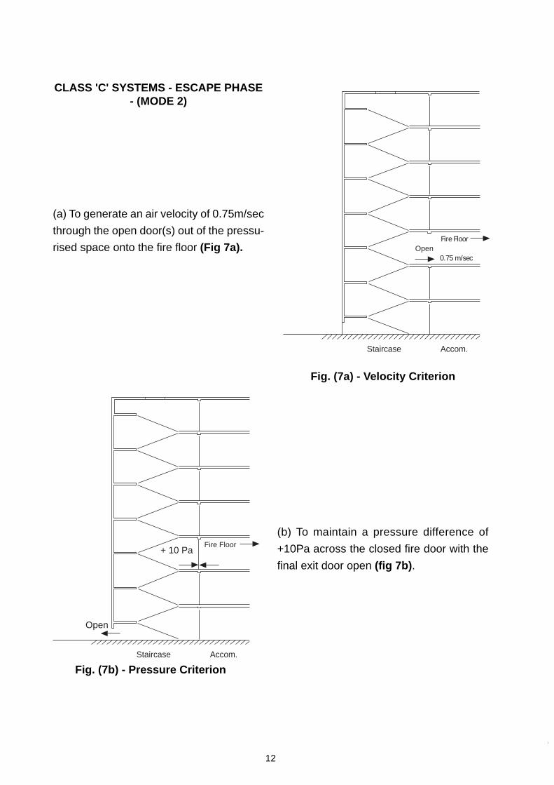
CLASS 'C' SYSTEMS - ESCAPE PHASE- (MODE 2)
(a) To generate an air velocity of 0.75m/sec
through the open door(s) out of the pressu-
rised space onto the fire floor (Fig 7a).
Fig. (7a) - Velocity Criterion
(b) To maintain a pressure difference of
+10Pa across the closed fire door with the
final exit door open (fig 7b) .
Fig. (7b) - Pressure Criterion
Staircase Accom.
Fire FloorOpen
0.75 m/sec
Staircase Accom.
+ 10 Pa
Open
Fire Floor
13
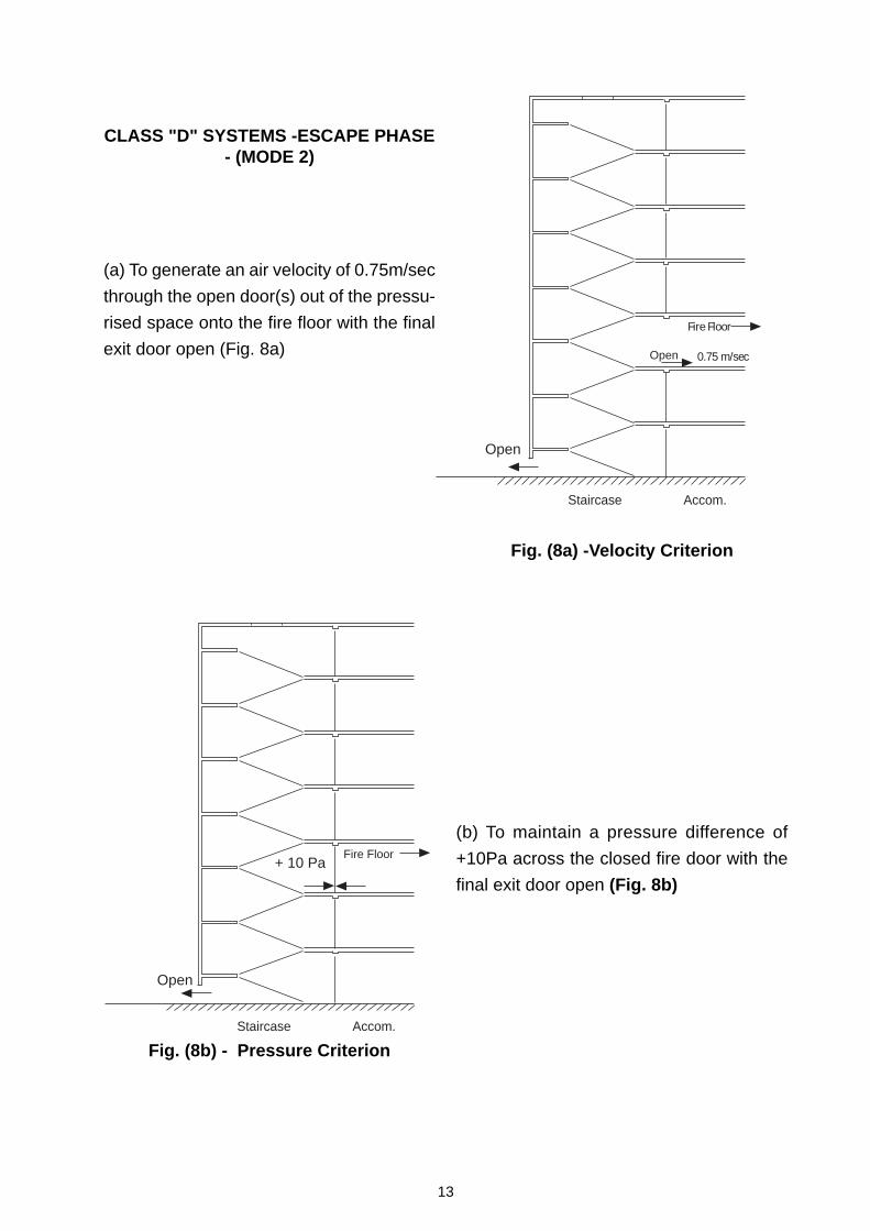
(a) To generate an air velocity of 0.75m/sec
through the open door(s) out of the pressu-
rised space onto the fire floor with the final
exit door open (Fig. 8a)
Fig. (8a) -Velocity Criterion
Fig. (8b) - Pressure Criterion
(b) To maintain a pressure difference of
+10Pa across the closed fire door with the
final exit door open (Fig. 8b)
CLASS "D" SYSTEMS -ESCAPE PHASE- (MODE 2)
Staircase Accom.
+ 10 Pa
Open
Fire Floor
Staircase Accom.
Fire Floor
Open
Open 0.75 m/sec
14
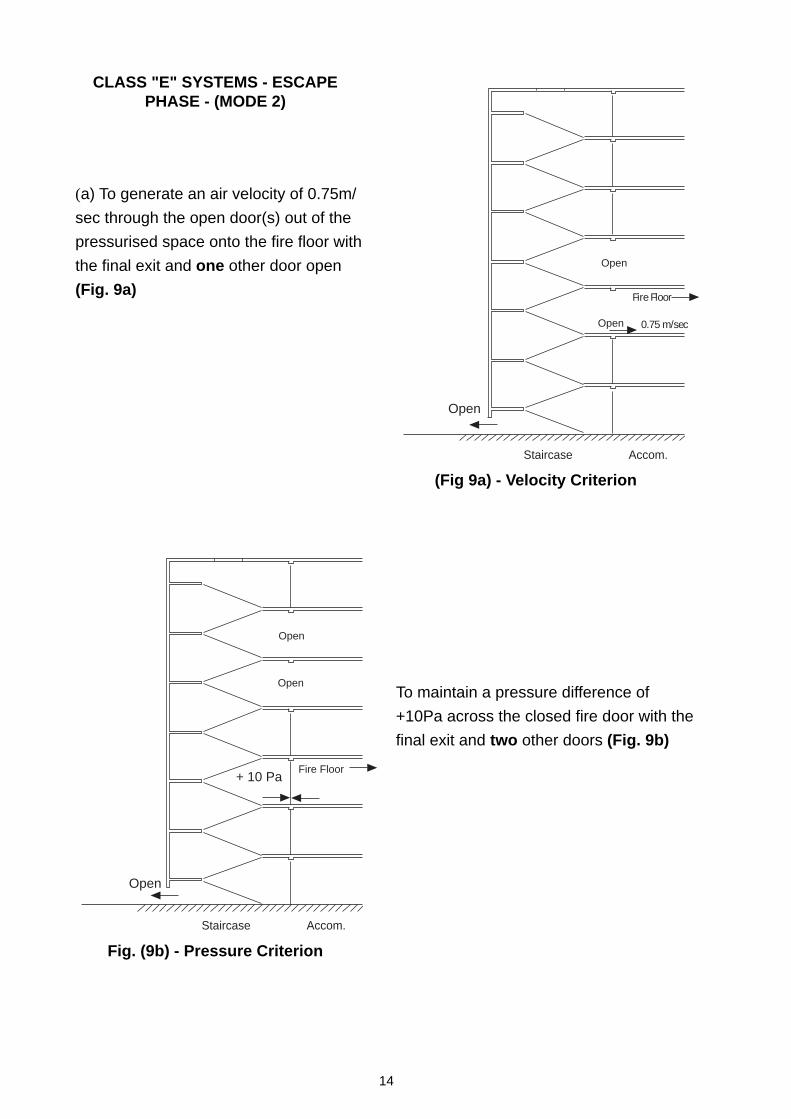
CLASS "E" SYSTEMS - ESCAPEPHASE - (MODE 2)
(a) To generate an air velocity of 0.75m/
sec through the open door(s) out of the
pressurised space onto the fire floor with
the final exit and one other door open
(Fig. 9a)
(Fig 9a) - Velocity Criterion
To maintain a pressure difference of
+10Pa across the closed fire door with the
final exit and two other doors (Fig. 9b)
Fig. (9b) - Pressure Criterion
Staircase Accom.
Fire Floor
Open
Open
Open 0.75 m/sec
Staircase Accom.
+ 10 Pa
Open
Open
Open
Fire Floor
15
3.3 EXHAUST AIR SYSTEM
The EXHAUST AIR system must be de-signed to provide a LOW RESISTANCEroute for the supply air to leave the buildingvia the fire floor.
This can be achieved by one of four methods:-
a) Via the leakage provided by the windowcracks on the outside of the building.
In practice this is unrealistic. The area pro-vided is unlikely to be sufficient.
b) Through automatically opened windowsor vents around the perimeter of thebuilding.
This is a possibility where the area con-cerned has sufficient outside wall space toaccommodate the vent area necessary.Operating Mode 2 would require almost 0.5m2 of vent area on every floor for each pres-surised staircase.
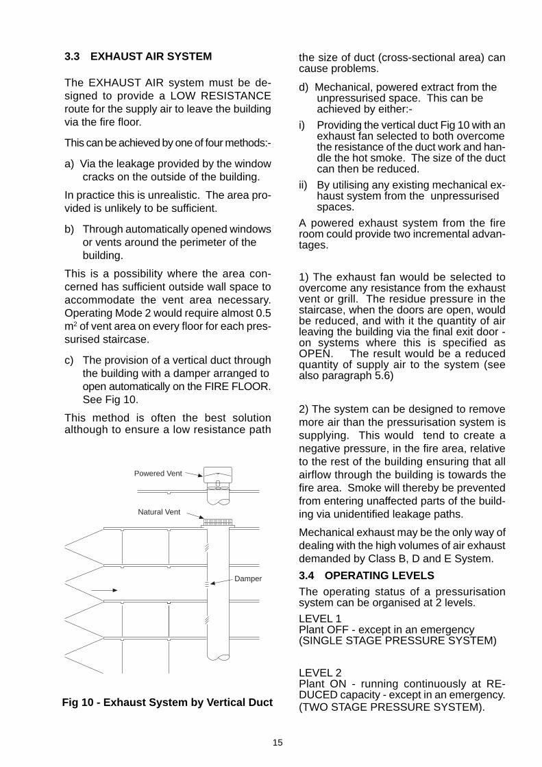
c) The provision of a vertical duct throughthe building with a damper arranged toopen automatically on the FIRE FLOOR.See Fig 10.
This method is often the best solutionalthough to ensure a low resistance path
Fig 10 - Exhaust System by Vertical Duct
3.4 OPERATING LEVELSThe operating status of a pressurisationsystem can be organised at 2 levels.
LEVEL 1Plant OFF - except in an emergency(SINGLE STAGE PRESSURE SYSTEM)
LEVEL 2Plant ON - running continuously at RE-DUCED capacity - except in an emergency.(TWO STAGE PRESSURE SYSTEM).
the size of duct (cross-sectional area) cancause problems.
d) Mechanical, powered extract from theunpressurised space. This can beachieved by either:-
i) Providing the vertical duct Fig 10 with anexhaust fan selected to both overcomethe resistance of the duct work and han-dle the hot smoke. The size of the ductcan then be reduced.
ii) By utilising any existing mechanical ex-haust system from the unpressurisedspaces.
A powered exhaust system from the fireroom could provide two incremental advan-tages.
1) The exhaust fan would be selected toovercome any resistance from the exhaustvent or grill. The residue pressure in thestaircase, when the doors are open, wouldbe reduced, and with it the quantity of airleaving the building via the final exit door -on systems where this is specified asOPEN. The result would be a reducedquantity of supply air to the system (seealso paragraph 5.6)
2) The system can be designed to removemore air than the pressurisation system issupplying. This would tend to create anegative pressure, in the fire area, relativeto the rest of the building ensuring that allairflow through the building is towards thefire area. Smoke will thereby be preventedfrom entering unaffected parts of the build-ing via unidentified leakage paths.
Mechanical exhaust may be the only way ofdealing with the high volumes of air exhaustdemanded by Class B, D and E System.
Powered Vent
Natural Vent
Damper
16
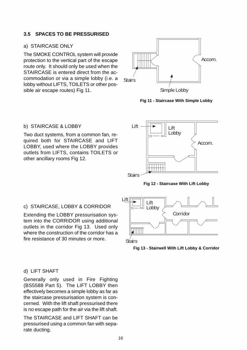
3.5 SPACES TO BE PRESSURISED
a) STAIRCASE ONLY
The SMOKE CONTROL system will provideprotection to the vertical part of the escaperoute only. It should only be used when theSTAIRCASE is entered direct from the ac-commodation or via a simple lobby (i.e. alobby without LIFTS, TOILETS or other pos-sible air escape routes) Fig 11.
b) STAIRCASE & LOBBY
Two duct systems, from a common fan, re-quired both for STAIRCASE and LIFTLOBBY, used where the LOBBY providesoutlets from LIFTS, contains TOILETS orother ancillary rooms Fig 12.
c) STAIRCASE, LOBBY & CORRIDOR
Extending the LOBBY pressurisation sys-tem into the CORRIDOR using additionaloutlets in the corridor Fig 13. Used onlywhere the construction of the corridor has afire resistance of 30 minutes or more.
d) LIFT SHAFT
Generally only used in Fire Fighting(BS5588 Part 5). The LIFT LOBBY theneffectively becomes a simple lobby as far asthe staircase pressurisation system is con-cerned. With the lift shaft pressurised thereis no escape path for the air via the lift shaft.
The STAIRCASE and LIFT SHAFT can bepressurised using a common fan with sepa-rate ducting.
Fig 11 - Staircase With Simple Lobby
Fig 12 - Staircase With Lift Lobby
Fig 13 - Stairwell With Lift Lobby & Corridor
Accom.
Stairs
Simple Lobby
Lift LiftLobby
Accom.
Stairs
Stairs
LiftLobby
Lift
Corridor
17
4.1 DESIGN BACKGROUND
The design of any air movement system in-volves an answer to the question:-
“How do I establish the AIR VOLUMErequired to make this system work?”
With a Pressurisation System designed forSMOKE CONTROL there is an initial ques-tion to be answered.
“What PRESSURE (or VELOCITY) do Ineed to develop in the escape routes tohold back the smoke?”
The answers to both these questions wereprovided as a result of research work by P.J.Hobson and L. J Stewart in the U.K. duringthe 1960’s and 1970’s (Ref 6). This workled directly to the publication of the U.K.code of Practice for Pressurisation Systems- BS5588 Part 4 in 1978 (Ref 7), now super-seded by the current code of practice inBS5588 Part 4:1998 (Ref 8).
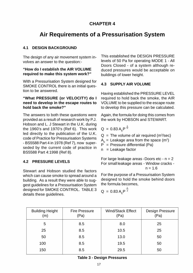
4.2 PRESSURE LEVELS
Stewart and Hobson studied the factorswhich can cause smoke to spread around abuilding. As a result they were able to sug-gest guidelines for a Pressurisation Systemdesigned for SMOKE CONTROL. TABLE 3details these guidelines.
CHAPTER 4
Air Requirements of a Pressurisation System
5 8.5 8.0 25
25 8.5 10.5 25
50 8.5 13.0 50
100 8.5 19.5 50
150 8.5 29.5 50
Building Height Fire Pressure Wind/Stack Effect Design Pressure (m) (Pa) (Pa) (Pa)
Table 3 - Design Pressures
This established the DESIGN PRESSURElevels of 50 Pa for operating MODE 1 - AllDoors Closed - of a system although re-duced pressures would be acceptable onbuildings of lower height.
4.3 SUPPLY AIR VOLUME
Having established the PRESSURE LEVELrequired to hold back the smoke, the AIRVOLUME to be supplied to the escape routeto develop this pressure can be calculated.
Again, the formula for doing this comes fromthe work by HOBSON and STEWART.
Q = 0.83 AEP
Q = The volume of air required (m3/sec)A
E = Leakage area from the space (m2)
P = Pressure differential (Pa)n = Leakage factor
For large leakage areas - Doors etc - n = 2For small leakage areas - Window cracks -
n = 1.6
For the purpose of a Pressurisation Systemdesigned to hold the smoke behind doorsthe formula becomes,
Q = 0.83 AEP
1n
12
18
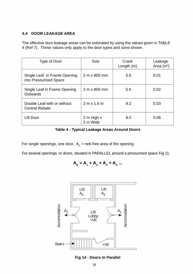
Type of Door Size Crack LeakageLength (m) Area (m2)
Single Leaf in Frame Opening 2 m x 800 mm 5.6 0.01into Pressurised Space
Single Leaf in Frame Opening 2 m x 800 mm 5.6 0.02Outwards
Double Leaf with or without 2 m x 1.6 m 9.2 0.03Central Rebate
Lift Door 2 m High x 8.0 0.062 m Wide
Table 4 - Typical Leakage Areas Around Doors
For single openings, one door, AE = nett free area of the opening.
For several openings, or doors, situated in PARALLEL around a pressurised space Fig 11.
AE = A1 + A2 + A3 + A4 ...
Fig 14 - Doors In Parallel
4.4 DOOR LEAKAGE AREA
The effective door leakage areas can be estimated by using the values given in TABLE4 (Ref 7). These values only apply to the door types and sizes shown.
Stairs
Acco
mod
atio
n
LiftA4
Acco
mod
atio
n
LiftA3
+VE
A2 A1LiftLobby+VE
19
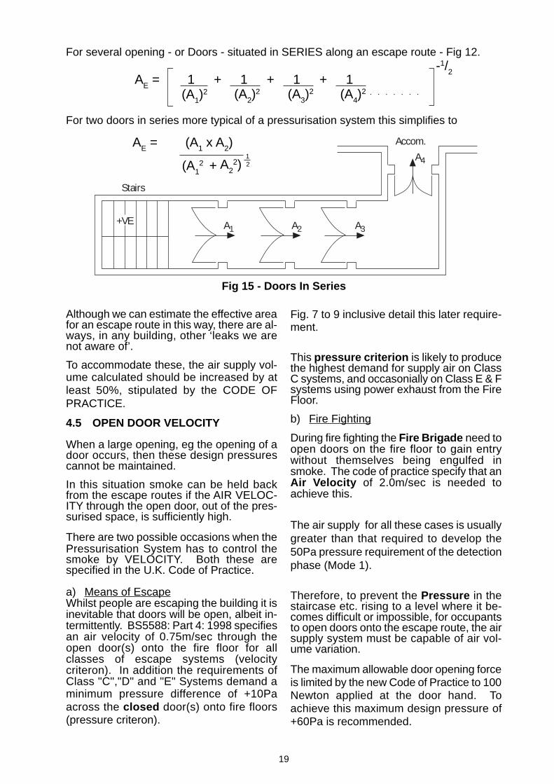
Fig 15 - Doors In Series
For two doors in series more typical of a pressurisation system this simplifies to
A22)(A1
2 +
AE = 1 + 1 + 1 + 1
AE = (A1 x A2)
Although we can estimate the effective areafor an escape route in this way, there are al-ways, in any building, other ‘leaks we arenot aware of’.
To accommodate these, the air supply vol-ume calculated should be increased by atleast 50%, stipulated by the CODE OFPRACTICE.
4.5 OPEN DOOR VELOCITY
When a large opening, eg the opening of adoor occurs, then these design pressurescannot be maintained.
In this situation smoke can be held backfrom the escape routes if the AIR VELOC-ITY through the open door, out of the pres-surised space, is sufficiently high.
There are two possible occasions when thePressurisation System has to control thesmoke by VELOCITY. Both these arespecified in the U.K. Code of Practice.
a) Means of EscapeWhilst people are escaping the building it isinevitable that doors will be open, albeit in-termittently. BS5588: Part 4: 1998 specifiesan air velocity of 0.75m/sec through theopen door(s) onto the fire floor for allclasses of escape systems (velocitycriteron). In addition the requirements ofClass "C","D" and "E" Systems demand aminimum pressure difference of +10Paacross the closed door(s) onto fire floors(pressure criteron).
Fig. 7 to 9 inclusive detail this later require-ment.
This pressure criterion is likely to producethe highest demand for supply air on ClassC systems, and occasonially on Class E & Fsystems using power exhaust from the FireFloor.
b) Fire Fighting
During fire fighting the Fire Brigade need toopen doors on the fire floor to gain entrywithout themselves being engulfed insmoke. The code of practice specify that anAir Velocity of 2.0m/sec is needed toachieve this.
The air supply for all these cases is usuallygreater than that required to develop the50Pa pressure requirement of the detectionphase (Mode 1).
Therefore, to prevent the Pressure in thestaircase etc. rising to a level where it be-comes difficult or impossible, for occupantsto open doors onto the escape route, the airsupply system must be capable of air vol-ume variation.
The maximum allowable door opening forceis limited by the new Code of Practice to 100Newton applied at the door hand. Toachieve this maximum design pressure of+60Pa is recommended.
For several opening - or Doors - situated in SERIES along an escape route - Fig 12.
(A1)2 (A2)
2 (A3)2 (A4)
2 ○ ○ ○ ○ ○ ○ ○ ○
-1/2
12
A1 A2 A3
A4
+VE
Stairs
Accom.
20
A Pressurisation System designed toprotect an escape route used only forMEANS OF ESCAPE is required to de-velop 50 Pa Pressure in the escaperoute when all the doors are closed,and up to 0.75 m/sec VELOCITYthrough the open door on the fire floor,OR a pressure, difference of +10PAacross the closed fire floor door, whichever is greater, under conditions, illus-trated Figs 5, 7 8 and 9.
A Pressurisation System designed toprotect an escape route which is to beused both for MEANS OF ESCAPEand FIRE FIGHTING is required toachieve a VELOCITY of 2 m/secthrough the open door on the fire floorunder the conditions illustrated by Fig6, in addition to the requirementsspecified in (a) above.
A Pressurisation System must includea low resistance path to enable thepressurising air to escape from theunpressurised areas of the building -discussed in 2.3.
If mechanical exhaust is used then theFANS must be capable of handling thehot smoke involved and comply withthe requirements of BS7346 Part 2.
Here then are the simple tools which allowus to establish the AIR SUPPLY and EX-HAUST requirements of a PRESSURISA-TION SYSTEM for SMOKE CONTROL.They will apply to any combination ofPRESSURE or DOOR VELOCITIESSPECIFIED IN THE VARIOUS NATIONALCodes of Practice.
a)
b)
c)
4.6 REQUIREMENTS OF APRESSURISATION SYSTEM
21
5.1 WORKED EXAMPLE
The best method for establishing the re-quirements of SUPPLY FANS for pressuri-sation systems is to select the fans for atypical pressurised staircase.
The example chosen is perhaps the sim-plest form of a Pressurised Staircase forSmoke Control, and as such may be unreal.However, using a simple example, it iseasier to determine and highlight the fanrequirements.
Example: A Staircase, Fig 16 serves 6floors. There is a double door to outsideat ground level and single doors into theaccommodation on each floor.
5.2 CALCULATION PROCEDURE
A complete and detailed calculation proce-dure, with worked examples, is outlined inBS5588 Part 4:1998. Designers should fol-low this approach when seeking approvalfor their schemes.
With the possible exceptions outlined inparagraph 4.5(a) the size of the supply fanfor pressurisation system is determined bythe velocity through the open door (s) -MODE 2 or MODE 3. The airflowrequirments of MODE 1 and are thenachieved by either:-
a) Wasting the excess air to atmosphere or
b) Reducing the volume flow of the fan.
The worked example in this paper employsa much simplified method of calculation de-veloped and used by Mr C. H. Moss (Ref10). This method is very useful when sizingand selecting the supply air fan (s). It will al-ways over estimate the air supply require-ments by:-
CHAPTER 5
Fan Selections
a) The addition of 50% to the calculated air-flows at MODE 1.
b) Assuming that, when the door(s) asspecified, are open (MODE 2 ANDMODE 3), the pressure of 50 Pa is main-tained in the staircase and lift lobbies.
However, buildings in general, and stair-cases in particular are notoriously ‘leaky’.Equally, incorrect and ill-fitting doors wouldincrease the airflow demands. Over sizingthe supply fan at the design stage can provebeneficial during commissioning.
This highlights one of the requirementsof a supply air fan - that it’s air volumeoutput be easily adjustable on site. Axialflow fans with variable geometryimpellers meet this requirement.
5.3 EXHAUST AIR FANS
The sizing of any EXHAUST AIR FANS willalso be determined from the system calcula-tion procedure. These fans must be capableof handling hot air smoke and comply withBS7346 - Part 2 (Ref 2) or similar testingstandard.
BS5588 - Part 4: 1998 recommends thatexhust air fans be capable of surviving
600°C for 2 hours in unsprinklered buildings300°C for 2 hours in sprinklered buildings.
At the time of writing neither of these specifi-cations are in line with the high temperaturecategories specified in BS7346 Part 2 or theHence designers are recommended to seekclarification from Building Control.
22
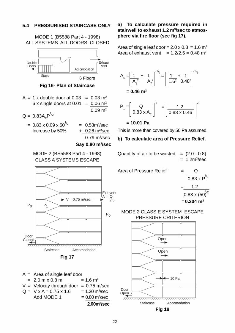
A = 1 x double door at 0.03 = 0.03 m2
6 x single doors at 0.01 = 0.06 m2
0.09 m2
Q = 0.83AEP1/2
= 0.83 x 0.09 x 501/2 = 0.53m3/sec
Increase by 50% + 0.26 m3/sec0.79 m3/sec
Say 0.80 m 3/sec
Fig 16- Plan of Staircase
A = Area of single leaf door= 2.0 m x 0.8 m = 1.6 m2
V = Velocity through door = 0.75 m/secQ = V x A = 0.75 x 1.6 = 1.20 m3/sec
Add MODE 1 = 0.80 m3/sec 2.00m3/sec
Fig 17
MODE 1 (B5588 Part 4 - 1998)ALL SYSTEMS ALL DOORS CLOSED
b) To calculate area of Pressure Relief.
MODE 2 (BS5588 Part 4 - 1998)
6 Floors
This is more than covered by 50 Pa assumed.
5.4 PRESSURISED STAIRCASE ONLY
= 1 + 11.62
2
P1 = Q 0.83 x AE
2
= 1.20.83 x 0.46
= 10.01 Pa
A22
= 0.46 m2
0.482
-A
E = 1 + 1
A1
2
-1/2
Quantity of air to be wasted = (2.0 - 0.8)= 1.2m3/sec
Area of Pressure Relief = Q
0.83 x P
= 1.2
0.83 x (50) = 0.204 m2
a) To calculate pressure required instairwell to exhaust 1.2 m 3/sec to atmos-phere via fire floor (see fig 17).
Area of single leaf door = 2.0 x 0.8 = 1.6 m2
Area of exhaust vent = 1.2/2.5 = 0.48 m2
MODE 2 CLASS E SYSTEM ESCAPEPRESSURE CRITERION
Fig 18
-1/2-1/2
1/2
1/2
Stairs
Accomodation
DoubleDoors
ExhaustVent
CLASS A SYSTEMS ESCAPE
Exit ventA = Q 2.5
P0
Staircase Accomodation
DoorClosed
V = 0.75 m/sec
P0 P1
Staircase Accomodation
DoorOpen
Open
Open
10 Pa
23
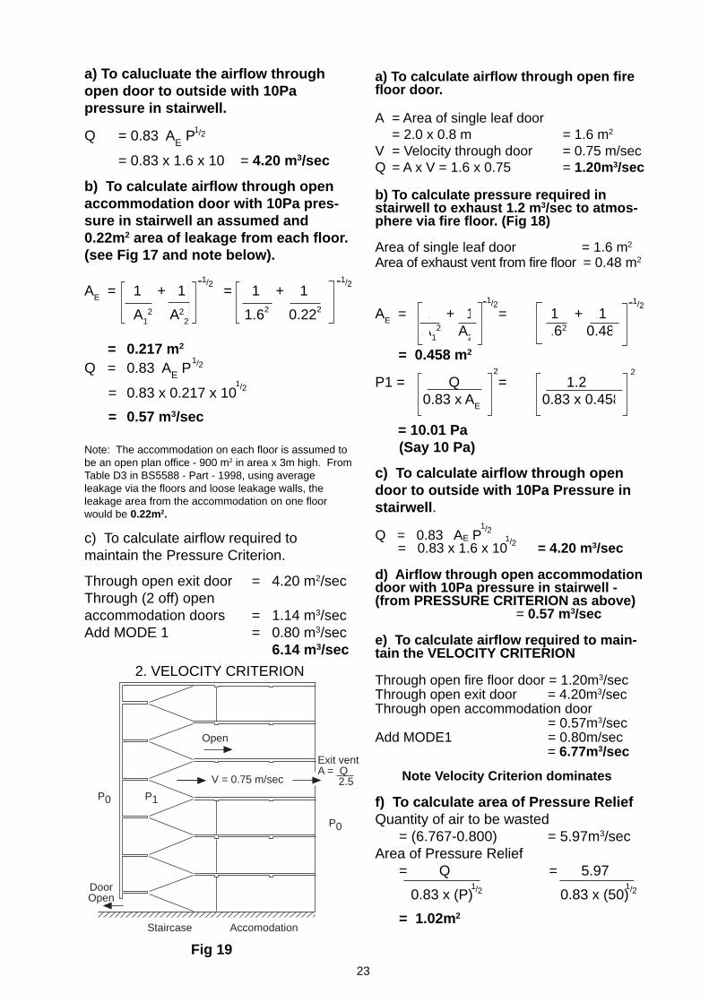
a) To calculate airflow through open firefloor door.
A = Area of single leaf door= 2.0 x 0.8 m = 1.6 m2
V = Velocity through door = 0.75 m/secQ = A x V = 1.6 x 0.75 = 1.20m3/sec
b) To calculate pressure required instairwell to exhaust 1.2 m 3/sec to atmos-phere via fire floor. (Fig 18)
Area of single leaf door = 1.6 m2
Area of exhaust vent from fire floor = 0.48 m2
AE = 1 + 1 = 1 + 1 A1
2 A22 1.62 0.482
= 0.458 m2
P1 = Q = 1.2 0.83 x A
E 0.83 x 0.458
= 10.01 Pa (Say 10 Pa)
c) To calculate airflow through opendoor to outside with 10Pa Pressure instairwell .
Q = 0.83 AE P = 0.83 x 1.6 x 10 = 4.20 m3/sec
d) Airflow through open accommodationdoor with 10Pa pressure in stairwell -(from PRESSURE CRITERION as above) = 0.57 m3/sec
e) To calculate airflow required to main-tain the VELOCITY CRITERION
Through open fire floor door = 1.20m3/secThrough open exit door = 4.20m3/secThrough open accommodation door
= 0.57m3/secAdd MODE1 = 0.80m/sec
= 6.77m3/sec
f) To calculate area of Pressure ReliefQuantity of air to be wasted = (6.767-0.800) = 5.97m3/secArea of Pressure Relief = Q = 5.97
0.83 x (P) 0.83 x (50)
= 1.02m2
Note Velocity Criterion dominates
2
2. VELOCITY CRITERION
Fig 19
1/2
-1/2 -1/2
1/2
-1/2-1/2
2
1/21/2
1/2 1/2
1/2
a) To calucluate the airflow throughopen door to outside with 10Papressure in stairwell.
Q = 0.83 AE P
= 0.83 x 1.6 x 10 = 4.20 m3/sec
b) To calculate airflow through openaccommodation door with 10Pa pres-sure in stairwell an assumed and0.22m2 area of leakage from each floor.(see Fig 17 and note below).
AE = 1 + 1 = 1 + 1
A12 A2
2 1.62 0.222
= 0.217 m2
Q = 0.83 AE P
= 0.83 x 0.217 x 10
= 0.57 m3/sec
Note: The accommodation on each floor is assumed tobe an open plan office - 900 m2 in area x 3m high. FromTable D3 in BS5588 - Part - 1998, using averageleakage via the floors and loose leakage walls, theleakage area from the accommodation on one floorwould be 0.22m2.
c) To calculate airflow required tomaintain the Pressure Criterion.
Through open exit door = 4.20 m2/secThrough (2 off) openaccommodation doors = 1.14 m3/secAdd MODE 1 = 0.80 m3/sec
6.14 m3/sec
Exit ventA = Q 2.5
P0
Staircase Accomodation
DoorOpen
V = 0.75 m/sec
P0 P1
Open
24
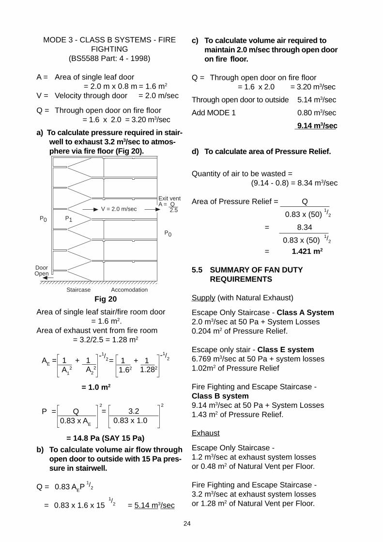
c) To calculate volume air required tomaintain 2.0 m/sec through open dooron fire floor.
Q = Through open door on fire floor = 1.6 x 2.0 = 3.20 m3/sec
Through open door to outside 5.14 m3/sec
Add MODE 1 0.80 m3/sec
9.14 m3/sec
d) To calculate area of Pressure Relief.
Quantity of air to be wasted = (9.14 - 0.8) = 8.34 m3/sec
Area of Pressure Relief = Q
0.83 x (50)
= 8.34
0.83 x (50)= 1.421 m2
5.5 SUMMARY OF FAN DUTYREQUIREMENTS
Supply (with Natural Exhaust)
Escape Only Staircase - Class A System2.0 m3/sec at 50 Pa + System Losses0.204 m2 of Pressure Relief.
Escape only stair - Class E system6.769 m3/sec at 50 Pa + system losses1.02m2 of Pressure Relief
Fire Fighting and Escape Staircase -Class B system9.14 m3/sec at 50 Pa + System Losses1.43 m2 of Pressure Relief.
Exhaust
Escape Only Staircase -1.2 m3/sec at exhaust system lossesor 0.48 m2 of Natural Vent per Floor.
Fire Fighting and Escape Staircase -3.2 m3/sec at exhaust system lossesor 1.28 m2 of Natural Vent per Floor.
MODE 3 - CLASS B SYSTEMS - FIREFIGHTING
(BS5588 Part: 4 - 1998)
A = Area of single leaf door = 2.0 m x 0.8 m = 1.6 m2
V = Velocity through door = 2.0 m/sec
Q = Through open door on fire floor = 1.6 x 2.0 = 3.20 m3/sec
a) To calculate pressure required in stair-well to exhaust 3.2 m 3/sec to atmos-phere via fire floor (Fig 20).
1/2
1/2
2
AE = 1 + 1 A1
2 A22
= 1.0 m2
2
= 3.2 0.83 x 1.0
1.282
= 14.8 Pa (SAY 15 Pa)
-1/2 -1/2 = 1 + 1
1.62
Area of single leaf stair/fire room door= 1.6 m2.
Area of exhaust vent from fire room= 3.2/2.5 = 1.28 m2
Fig 20
P = Q0.83 x AE
Exit ventA = Q 2.5
P0
Staircase Accomodation
DoorOpen
V = 2.0 m/sec
P0 P1
b) To calculate volume air flow throughopen door to outside with 15 Pa pres-sure in stairwell.
Q = 0.83 AEP
= 0.83 x 1.6 x 15 = 5.14 m3/sec1/
2
1/2
25
5.6 POWERED EXHAUST
The air duty requirements detailed at Para-graph 5.5 are calculated with the pressuris-ing airflow exhausting from the fire floorthrough a natural vent. This results in anincreased airflow through the open fire doorto outside.
Fan powered exhaust would eliminate theneed for this increase in the supply fan duty.The exhaust air fan could be selected toproduce zero pressure on the fire floor.
Hence, for the example shown, the supplyair fan would be sized to deliver 7.2 m3/secfor MODE 3 (reduced from 9.14 m3/sec).The exhaust air fan would need to handle3.2 m3/sec.
The amount of air to be wasted via the pres-sure relief damper would fall to 6.4 m3/sec,thereby reducing the size of the PRES-SURE RELIEF DAMPER from 1.43 m2 to1.09 m2.
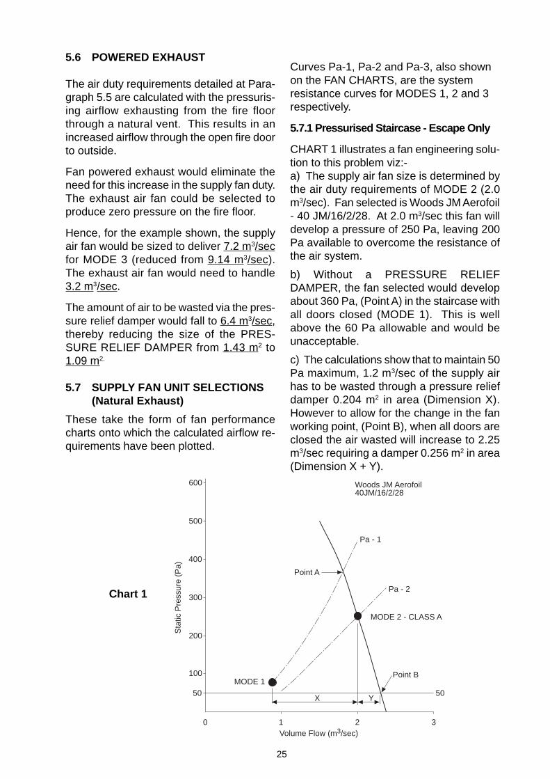
5.7 SUPPLY FAN UNIT SELECTIONS(Natural Exhaust)
These take the form of fan performancecharts onto which the calculated airflow re-quirements have been plotted.
Curves Pa-1, Pa-2 and Pa-3, also shownon the FAN CHARTS, are the systemresistance curves for MODES 1, 2 and 3respectively.
5.7.1 Pressurised Staircase - Escape Only
CHART 1 illustrates a fan engineering solu-tion to this problem viz:-a) The supply air fan size is determined bythe air duty requirements of MODE 2 (2.0m3/sec). Fan selected is Woods JM Aerofoil- 40 JM/16/2/28. At 2.0 m3/sec this fan willdevelop a pressure of 250 Pa, leaving 200Pa available to overcome the resistance ofthe air system.
b) Without a PRESSURE RELIEFDAMPER, the fan selected would developabout 360 Pa, (Point A) in the staircase withall doors closed (MODE 1). This is wellabove the 60 Pa allowable and would beunacceptable.
c) The calculations show that to maintain 50Pa maximum, 1.2 m3/sec of the supply airhas to be wasted through a pressure reliefdamper 0.204 m2 in area (Dimension X).However to allow for the change in the fanworking point, (Point B), when all doors areclosed the air wasted will increase to 2.25m3/sec requiring a damper 0.256 m2 in area(Dimension X + Y).
Chart 1
100
200
300
400
500
600
1 2 3
50
Point A
MODE 1
X Y50
Volume Flow (m3/sec)
Sta
tic P
ress
ure
(Pa)
Woods JM Aerofoil40JM/16/2/28
Pa - 1
Pa - 2
0
Point B
MODE 2 - CLASS A
26
This excess becomes of increased impor-tance on system with high resistanceductwork systems, and demonstrates theneed for supply fan to have steep VOL-UME/PRESSURE performance charac-teristics (Axial Flow Fans in preferenceto Centrifugal).
5.7.2 Pressurised Staircase - Fire fighting & Escape
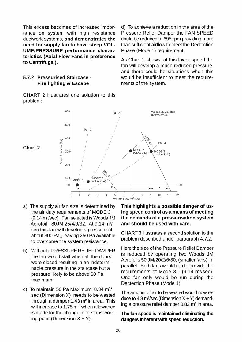
CHART 2 illustrates one solution to thisproblem:-
Chart 2
a) The supply air fan size is determined bythe air duty requirements of MODE 3(9.14 m3/sec). Fan selected is Woods JM
Aerofoil - 80JM 25/4/9/32. At 9.14 m3/sec this fan will develop a pressure ofabout 300 Pa,, leaving 250 Pa availableto overcome the system resistance.
b) Without a PRESSURE RELIEF DAMPERthe fan would stall when all the doorswere closed resulting in an indetermi-nable pressure in the staircase but apressure likely to be above 60 Pamaximum.
c) To maintain 50 Pa Maximum, 8.34 m3/sec (Dimension X) needs to be wastedthrough a damper 1.43 m2 in area. Thiswill increase to 1.75 m2 when allowanceis made for the change in the fans work-ing point (Dimension X + Y).
d) To achieve a reduction in the area of thePressure Relief Damper the FAN SPEEDcould be reduced to 695 rpm providing morethan sufficient airflow to meet the DectectionPhase (Mode 1) requirement.
As Chart 2 shows, at this lower speed thefan will develop a much reduced pressure,and there could be situations when thiswould be insufficient to meet the require-ments of the system.
This highlights a possible danger of us-ing speed control as a means of meetingthe demands of a pressurisation systemand should be used with care.
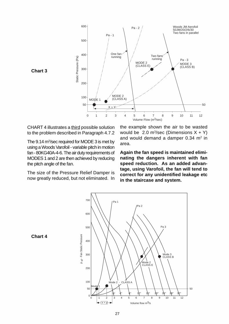
CHART 3 illustrates a second solution to theproblem described under paragraph 4.7.2.
Here the size of the Pressure Relief Damperis reduced by operating two Woods JMAerofoils 50 JM/20/2/6/30, (smaller fans), inparallel. Both fans would run to provide therequirements of Mode 3 - (9.14 m3/sec).One fan only would be run during theDectection Phase (Mode 1)
The amount of air to be wasted would now re-duce to 4.8 m3/sec (Dimension X + Y) demand-ing a pressure relief damper 0.82 m2 in area.
The fan speed is maintained eliminating thedangers inherent with speed reduction.
100
200
300
400
500
600
3 6 9
50
MODE 1
X Y50
Volume Flow (m3/sec)
Sta
tic P
ress
ure
(Pa)
Woods JM Aerofoil80JM/25/4/32
Pa - 1
Pa - 2
12
Pa - 3
MODE 3 (CLASS B)
695 rpm
1440 rpm
1 2 4 5 7 8 10 110
MODE 2(CLASS E)
MODE 2(CLASS A)
27
Chart 3
Chart 4
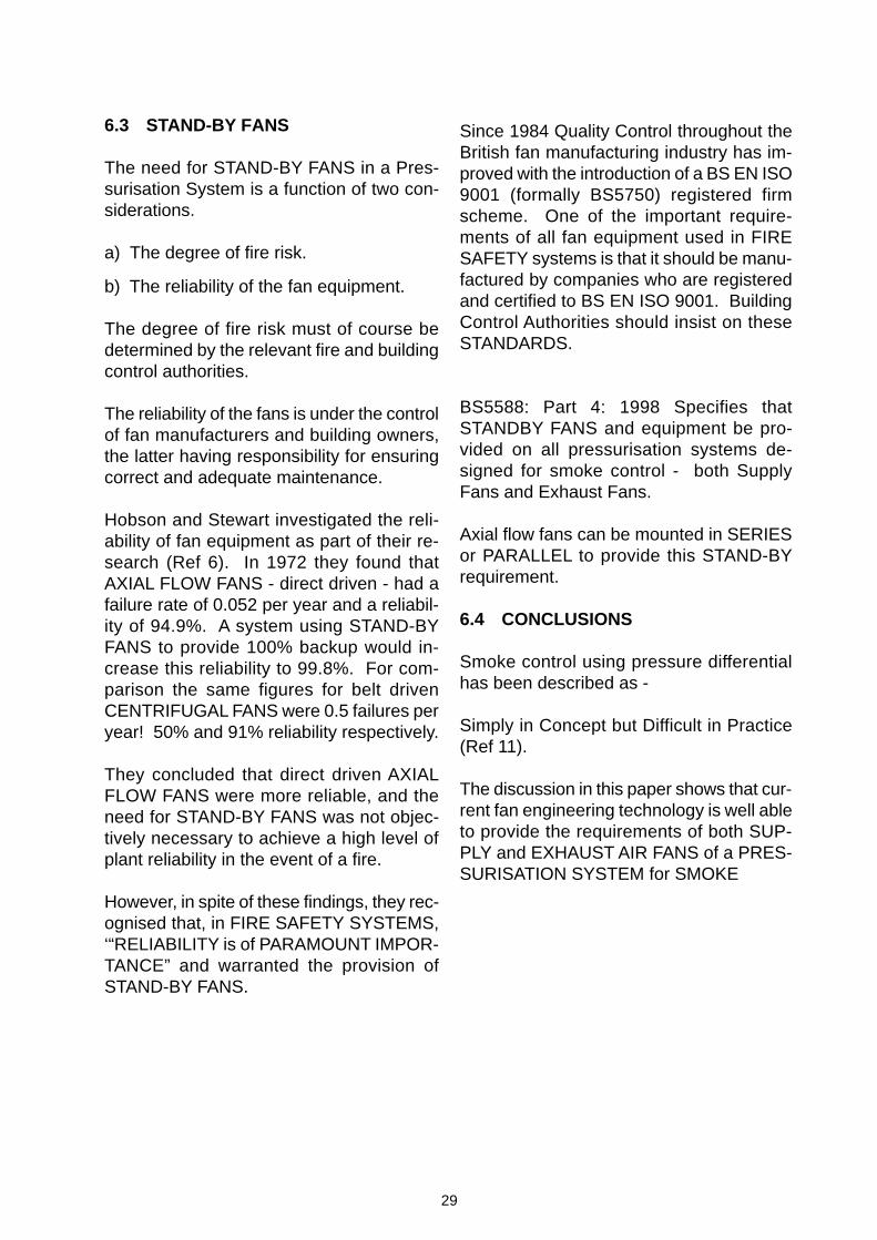
CHART 4 illustrates a third possible solutionto the problem described in Paragraph 4.7.2
The 9.14 m3/sec required for MODE 3 is met byusing a Woods Varofoil - variable pitch in motionfan - 80KG40A-4-6. The air duty requirements ofMODES 1 and 2 are then achieved by reducingthe pitch angle of the fan.
The size of the Pressure Relief Damper isnow greatly reduced, but not eliminated. In
the example shown the air to be wastedwould be 2.0 m3/sec (Dimensions X + Y)and would demand a damper 0.34 m2 inarea.
Again the fan speed is maintained elimi-nating the dangers inherent with fanspeed reduction. As an added advan-tage, using Varofoil, the fan will tend tocorrect for any unidentified leakage etcin the staircase and system.
100
200
300
400
500
600
3 6 9
50
MODE 2(CLASS A)MODE 1
X + Y50
Volume Flow (m3/sec)
Sta
tic P
ress
ure
(Pa)
Woods JM Aerofoil50JM/20/2/6/30Two fans in parallel
Pa - 1
Pa - 2
12
Pa - 3MODE 3(CLASS B)
1 2 4 5 7 8 10 11
Two fansrunning
One fanrunning
0
MODE 2(CLASS E)
100
200
300
400
500
600
700
50
00 1 2 3 4 5 6 7 8 9 1110 12
12° 32°28°24°20°16°8°
Mode 1
Pa 1
Pa 2
Pa 3
Volume flow m3/s
p sf
- F
an S
tatic
Pre
ssur
e
x + y
4°0°
50
Mode 2CLASS E
Mode 3CLASS B
Mode 2 - CLASS A

28
6.1 REQUIREMENTS OF APRESSURISATION FAN
The requirements of both SUPPLY and EX-HAUST fans in Pressurisation Systems canbe listed as follows:-
a) Supply Air Fans must be capable of vol-ume variation to meet the demands ofall three operating modes of the system.This is discussed in more details underparagraph 6.2
b) Supply Air Fans must be capable of dutychanges on site, to compensate for anyunder or over sizing inherent in the de-sign procedure.
c) Supply Air Fans should have a steepvolume/pressure curve to limit the airwastage through the pressure reliefdamper - and hence its size.
d) Supply Air Fans should maintain a highpressure capability ensuring that suffi-cient pressure is always available to thesystem. The use of variable speed fansto obtain the air volume changes needsexpert advice.
e) Exhaust Air Fans must be capable ofhandling the hot fire smoke at 600 °C inunsprinkerled, and 300°C in sprinkerledbuildings. They should comply withBS7346 Part 2 or similar testingstandard.
f) Fans should be lightweight, vibrationfree and easy to install.
g) All fans must be reliable in operationand be provided with complete and ad-equate maintenance instructions. Theyshould be manufactured by companieswho are certified to Quality AssuranceSystem BS EN ISO 9001 or equal.
CHAPTER 6
Fans for Pressurisation Systems
6.2 PROVIDING FOR VARIABLEAIR DUTY
Within the limits imposed by the general re-quirements of a supply air fan, providing forvariable air duty can best be achieved byone of the following methods.
a) A Constant Speed - Single fan withpressure relief damper.
b) Constant Speed - Twin fan with pres-sure relief damper - varying the numberof fans operating.
c) Variable Speed Fans.
d) Constant Speed - Variable pitch in mo-tion fans (Varofoil).
Constant speed fans ensure that the maxi-mum pressure capability of the fan is avail-able at all three operating modes of thesystem.
With variable speed fans this will not bethecase. The pressure developed by thefan varies with the speed squared. If thespeed of the fan is halved to achieve thelower air duty requirements of MODES 1and 2, then the pressure development is re-duced by four times.
The result could be insufficient pressurebeing available at the lower speed to pro-vide for the 50 Pa Mode One requirementand to overcome the resistance of the sys-tem ductwork. This could lead to the fanoperating in an unstable stall condition.
29
6.3 STAND-BY FANS
The need for STAND-BY FANS in a Pres-surisation System is a function of two con-siderations.
a) The degree of fire risk.
b) The reliability of the fan equipment.
The degree of fire risk must of course bedetermined by the relevant fire and buildingcontrol authorities.
The reliability of the fans is under the controlof fan manufacturers and building owners,the latter having responsibility for ensuringcorrect and adequate maintenance.
Hobson and Stewart investigated the reli-ability of fan equipment as part of their re-search (Ref 6). In 1972 they found thatAXIAL FLOW FANS - direct driven - had afailure rate of 0.052 per year and a reliabil-ity of 94.9%. A system using STAND-BYFANS to provide 100% backup would in-crease this reliability to 99.8%. For com-parison the same figures for belt drivenCENTRIFUGAL FANS were 0.5 failures peryear! 50% and 91% reliability respectively.
They concluded that direct driven AXIALFLOW FANS were more reliable, and theneed for STAND-BY FANS was not objec-tively necessary to achieve a high level ofplant reliability in the event of a fire.
However, in spite of these findings, they rec-ognised that, in FIRE SAFETY SYSTEMS,‘“RELIABILITY is of PARAMOUNT IMPOR-TANCE” and warranted the provision ofSTAND-BY FANS.
Since 1984 Quality Control throughout theBritish fan manufacturing industry has im-proved with the introduction of a BS EN ISO9001 (formally BS5750) registered firmscheme. One of the important require-ments of all fan equipment used in FIRESAFETY systems is that it should be manu-factured by companies who are registeredand certified to BS EN ISO 9001. BuildingControl Authorities should insist on theseSTANDARDS.
BS5588: Part 4: 1998 Specifies thatSTANDBY FANS and equipment be pro-vided on all pressurisation systems de-signed for smoke control - both SupplyFans and Exhaust Fans.
Axial flow fans can be mounted in SERIESor PARALLEL to provide this STAND-BYrequirement.
6.4 CONCLUSIONS
Smoke control using pressure differentialhas been described as -
Simply in Concept but Difficult in Practice(Ref 11).
The discussion in this paper shows that cur-rent fan engineering technology is well ableto provide the requirements of both SUP-PLY and EXHAUST AIR FANS of a PRES-SURISATION SYSTEM for SMOKE
30
APPENDIX ONE
References
1. J.A. Wild Fans for Fire Smoke Venting Woods Air Movement LtdTechnical Paper WTP20June 1989 (revised Nov. 1990)
2. J.H. Klote An overview of Smoke National Bureau of Standards.Control Technology Paper NBSIR 87-3626 1987.
3. P.H. Thomas Movement of Smoke in Institution of Fire EngineersHorizontal corridors Vol. 30 No. 72 1970.against an airflow.
4. G.A.C. Courtier The development of Axial Flow Institution of MechanicalJ.A. Wild Fans for the venting of Engineers Paper C401/016
hot fire smoke. March 1990.
5. BS7346 Part 2 Specification for powered smoke British Standards Institutionand heat exhausters. 1990.
6. P.J. Hobson Pressurisation of Escape Routes Fire Research Note 958L.J. Stewart in Buildings. December 1977.
7. BS5588 Part 4 Fire Precautions in the design of British Standards Institutionbuildings. Smoke control in prote- 1978cted escape routes usingpressurisation.
8. BS5588 Part 4 Fire Precautions in the design, British Standards Instiutioncontruction and use of buildings. 1998Code of practice for smoke controlusing PRESSURE DIFFERIENTIALS.
9. BS5588 Part 5 Fire Precautions in the design, British Standards Institutionconstruction and use of buildings. 1991.Code of Practice for FireFighting stairs and lifts.
10. C.H. Moss Pressurisation Systems using air Seminar at Woods ofmovement technology as a Colchester Ltd.Fire Safety Measure. February 1993.
11. E.G. Butcher Pressurisation - Fire Surveyors October 1993.A.C. Parnell Simple in Concept
Difficult in Practice.
This document has been produced as a general guide and its contents should not be construed as anyrepresentation on our part as to the quality or fitness of our products for any particular purpose, nor asproviding advice on the design of fire and smoke control systems. You are recommended to consult yourprofessional advisers on matters relating to the design and installation of any such systems.

31Ref: WTP 41