small vertical axis wind turbine - department of · pdf filesmall vertical axis wind turbine...
TRANSCRIPT
Small Vertical Axis Wind TurbineGerald Spencer III, B.S.1 Alec Calder, B.S.1 Sasha Barnett, B.S.1 Eric Johnson, B.S.1
Sam Gray, B.S.1 Glenn Fuller, B.S.1 Tom Nordenholz, PhD1,2
1California Maritime Academy, 2University of California – Berkeley
Abstract
This project involves the theoretical modeling, conceptual design, manufacturing an testing of asmall vertical axis wind turbine (VAWT). In the initial stages, the aerodynamics were modeled using asingle stream tube analysis combined with a blade element momentum model, and the electro-‐mechanical properties of a three-‐phase delta wound motor were found experimentally. The next phase utilized a custom MATLAB program to systematically determine the appropriate aerodynamic propertiesto achieve a rated wind speed of 10 m/s, whilst producing electrical power to charge portable electronic devices. Using these parameters, the structural design was completed to withstand the forces involved during operation. Testing was completed at the UC Davis Aeronautical Wind Tunnel Facility, where it wasfound that the design did not reach the speed required to make useful power. This discrepancy is due tothe fact that the turbine was designed for the steady operating state, but neglected the VAWT’s self-‐starting ability. It has since been determined that due to low Reynolds number effects and friction in the mechanical structure, the turbine was not able to sufficiently produce enough torque at lower rotational speeds to reach the designed state. Thus, it is recommended that for future designs the nature of small VAWT self-‐starting must be thoroughly accounted for in the design stage to achieve optimum performance. In particular, due to the short chord length required of a turbine of this size, the aerodynamics effects of low Reynolds numbers should be further researched to understand the relation to starting torque.
Overview
A vertical-‐axis wind turbine was chosen for this project over a horizontal-‐axis wind turbine for
several reasons. First, VAWTs have the ability to take wind from any direction, and do not need a yawing
mechanism. Secondly, it was determined that using an H-‐rotor would greatly simplify the blade design.
Thirdly, VAWTs tend to operate at a lower speed, which increases safety and produces less noise
pollution. Thus, it was hoped that each of these individual factors would culminate in a marketable wind
turbine that was also visually appealing.
Objective
Due to the depletion of fossil fuels, renewable energy is gaining popularity. In particular,
advancements in technology have allowed wind turbines to harness more of the available wind power
for commercial and residential use. As the initial investment has become affordable, more versatile off-‐
the-‐grid solutions are being brought to the market. Personal applications that are able to power small
electronic devices are becoming increasingly sought-‐after. Based on the performance specifications for
several consumer electronics, and the current market offerings for personal wind turbines, we believe
that designing a portable wind turbine to power small electronic devices is feasible.
1
Our basic concept consists of a simple-‐to-‐use, and versatile turbine. It has the options of being
placed in one spot for permanent use, or being moved from location to location for different power
needs. It features a compact, robust design that can be broken down and stored in a ‘cube’ for
transporting. This cube can be loaded onto a truck and be moved with the consumer to any location
where the consumer’s power needs are.
With that concept in mind, the target consumer would be African citizens who have basic power
needs in places that are lacking a reliable source of affordable energy. Examples of those power needs
can include things such as lighting, charging a cell phone or laptop, and other small devices. This means
that the wind turbine must be constructed with as little cost as possible, while still maintaining high
reliability. One of the main advantages to a cheap design means that materials to make repairs to the
turbine would be readily available at minimal cost.
Design Team
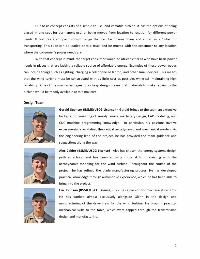
Gerald Spencer (BSME/USCG License) – Gerald brings to the team an extensive
background consisting of aerodynamics, machinery design, CAD modeling, and
CNC machine programming knowledge. In particular, his passions involve
experimentally validating theoretical aerodynamic and mechanical models. As
the engineering lead of the project, he has provided the team guidance and
suggestions along the way.
Alec Calder (BSME/USCG License) -‐ Alec has chosen the energy systems design
path at school, and has been applying those skills in assisting with the
aerodynamic modeling for the wind turbine. Throughout the course of the
project, he has refined the blade manufacturing process. He has developed
practical knowledge through automotive experience, which he has been able to
bring into the project.
Eric Johnson (BSME/USCG License) -‐ Eric has a passion for mechanical systems.
He has worked almost exclusively alongside Glenn in the design and
manufacturing of the drive train for the wind turbine. He brought practical
mechanical skills to the table, which were tapped through the transmission
design and manufacturing.
2
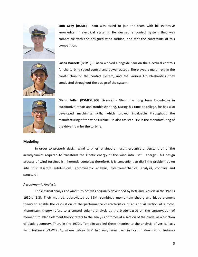
Sam Gray (BSME) -‐ Sam was asked to join the team with his extensive
knowledge in electrical systems. He devised a control system that was
compatible with the designed wind turbine, and met the constraints of this
competition.
Sasha Barnett (BSME) -‐ Sasha worked alongside Sam on the electrical controls
for the turbine speed control and power output. She played a major role in the
construction of the control system, and the various troubleshooting they
conducted throughout the design of the system.
Glenn Fuller (BSME/USCG License) -‐ Glenn has long term knowledge in
automotive repair and troubleshooting. During his time at college, he has also
developed machining skills, which proved invaluable throughout the
manufacturing of the wind turbine. He also assisted Eric in the manufacturing of
the drive train for the turbine.
Modeling
In order to properly design wind turbines, engineers must thoroughly understand all of the
aerodynamics required to transform the kinetic energy of the wind into useful energy. This design
process of wind turbines is inherently complex; therefore, it is convenient to distil the problem down
into four discrete subdivisions: aerodynamic analysis, electro-‐mechanical analysis, controls and
structural.
Aerodynamic Analysis
The classical analysis of wind turbines was originally developed by Betz and Glauert in the 1920’s
1930’s [1,2]. Their method, abbreviated as BEM, combined momentum theory and blade element
theory to enable the calculation of the performance characteristics of an annual section of a rotor.
Momentum theory refers to a control volume analysis at the blade based on the conservation of
momentum. Blade element theory refers to the analysis of forces at a section of the blade, as a function
of blade geometry. Then, in the 1970’s Templin applied these theories to the analysis of vertical-‐axis
wind turbines (VAWT) [3], where before BEM had only been used in horizontal-‐axis wind turbines
3
(HAWT). Templin’s single stream tube analysis was the foundation employed to model a small VAWT for
this project.
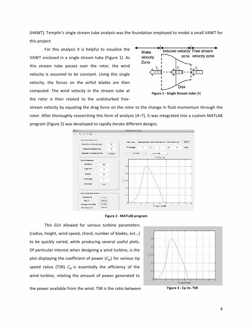
For this analysis it is helpful to visualize the
VAWT enclosed in a single stream tube (Figure 1). As
this stream tube passes over the rotor, the wind
velocity is assumed to be constant. Using this single
velocity, the forces on the airfoil blades are then
computed. The wind velocity in the stream tube at
the rotor is then related to the undisturbed free-‐
stream velocity by equating the drag force on the rotor to the change in fluid momentum through the
rotor. After thoroughly researching this form of analysis [4–7], it was integrated into a custom MATLAB
program (Figure 2) was developed to rapidly iterate different designs.
Figure 1 -‐ Single Stream tube [8]
Figure 2 -‐ MATLAB program
This GUI allowed for various turbine parameters
(radius, height, wind speed, chord, number of blades, ect…)
to be quickly varied, while producing several useful plots.
Of particular interest when designing a wind turbine, is the
plot displaying the coefficient of power (𝐶p) for various tip
speed ratios (TSR). 𝐶P is essentially the efficiency of the
wind turbine, relating the amount of power generated to
the power available from the wind. TSR is the ratio between Figure 3 -‐ Cp Vs. TSR
4
the tangential velocities of the blades to the free-‐stream velocity of the wind. When plotted against
each other, an optimum TSR can be identified as the point with the highest value for 𝐶P; this becomes
the theoretical steady operating state for the designed turbine, based on the program inputs.
It has been shown that in order to maximize 𝐶P for a given turbine, a solidity ratio of 0.3 is ideal
[8]. For rotors with 𝑛 blades, 𝜎 is defined as:
𝑛𝐶 𝜎 =
𝑅
Where C is the chord length of the blades, and R is the rotor radius. The rotor solidity, 𝜎, basically
describes what fraction of the swept area is solid and is something that affects the optimal tip speed
ratio. A low 𝜎 rotor has less blade area interacting with the wind and has to rely on a high TSR to cover
the same swept area, yielding less torque. Vice versa, a high 𝜎 rotor operates at a much lower TSR and
delivers more torque [9]. In order to increase starting torque for a small VAWT, a trade off between the
ideal 𝜎 and a realistic 𝜎 must be made. Several factors affect this decision, such as the undesirable
effects due to low Reynolds numbers and a small starting torque due to a low 𝜎. Thus, utilizing the
program developed above, a solidity of 0.36 was chosen in an attempt to mitigate these adverse effects
o a turbine of this size. Furthermore, lift and drag characteristics for the rotor had to optimized in order
to reduce any unnecessary power losses.
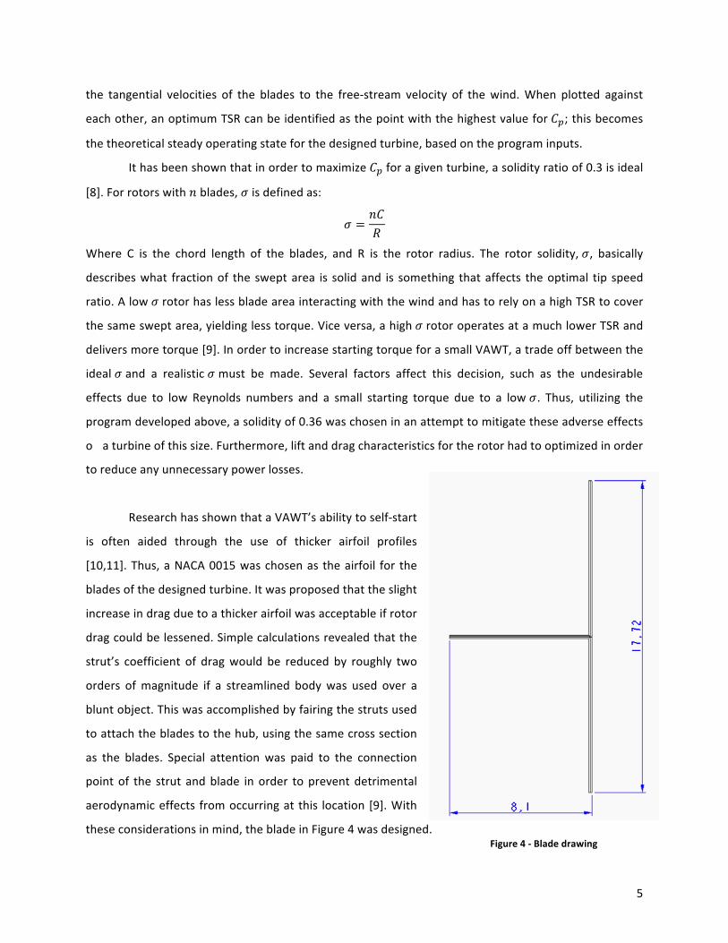
Research has shown that a VAWT’s ability to self-‐start
is often aided through the use of thicker airfoil profiles
[10,11]. Thus, a NACA 0015 was chosen as the airfoil for the
blades of the designed turbine. It was proposed that the slight
increase in drag due to a thicker airfoil was acceptable if rotor
drag could be lessened. Simple calculations revealed that the
strut’s coefficient of drag would be reduced by roughly two
orders of magnitude if a streamlined body was used over a
blunt object. This was accomplished by fairing the struts used
to attach the blades to the hub, using the same cross section
as the blades. Special attention was paid to the connection
point of the strut and blade in order to prevent detrimental
aerodynamic effects from occurring at this location [9]. With
these considerations in mind, the blade in Figure 4 was designed.Figure 4 -‐ Blade drawing
5

Electro-‐Mechanical Analysis
Figure 5 -‐ Passive Rectifier
Figure 5 above displays the basic principle of how the 3-‐phase AC power is transformed into DC
power. full bridge 6-‐diode passive rectifier only allows current to pass one way, but the diodes cause a
0.7 volt drop (1.4 V drop across the full rectifier). Because this project is using an active switching
rectifier, no voltage drop will be used when considering the dc output of the rectifier. In Figure 5 the
voltages in the key refer to the voltage at the output of the rectifier. For a constant voltage, the power
of a motor changes primarily with the current it produces. As the motor speed increases the voltage it
produces raises, this causes a larger voltage difference between the motor and the load (load voltage is
in the key at the right), and therefore increases the current and power.
Power Into Rectifier
Powe
r (W
) VDC=8
VDC=9
200
250
VDC=10
150
100
50
00 0.2 0.4 0.6 0.8 1 1.2 1.4 1.6 1.8 2
Motor Speed (RPM) x 104
Figure 6-‐ DC Motor Power
450 VDC=1
VDC=2400
VDC=3
VDC=4350 VDC=5
300 VDC=6
VDC=7
6
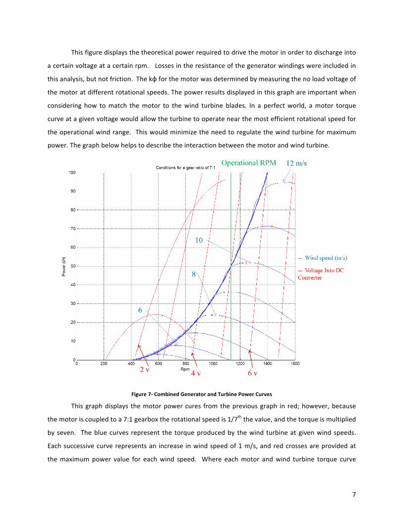
This figure displays the theoretical power required to drive the motor in order to discharge into
a certain voltage at a certain rpm. Losses in the resistance of the generator windings were included in
this analysis, but not friction. The kφ for the motor was determined by measuring the no load voltage of
the motor at different rotational speeds. The power results displayed in this graph are important when
considering how to match the motor to the wind turbine blades. In a perfect world, a motor torque
curve at a given voltage would allow the turbine to operate near the most efficient rotational speed for
the operational wind range. This would minimize the need to regulate the wind turbine for maximum
power. The graph below helps to describe the interaction between the motor and wind turbine.
Figure 7-‐ Combined Generator and Turbine Power Curves
This graph displays the motor power cures from the previous graph in red; however, because
the motor is coupled to a 7:1 gearbox the rotational speed is 1/7th the value, and the torque is multiplied
by seven. The blue curves represent the torque produced by the wind turbine at given wind speeds.
Each successive curve represents an increase in wind speed of 1 m/s, and red crosses are provided at
the maximum power value for each wind speed. Where each motor and wind turbine torque curve
7

meets represents a steady state condition for the wind turbine. For example, if the wind turbine was in 7
m/s of wind and discharging directly into a 5V sink, the wind turbine would rotate at about 1075 RPM
and produce 11 Watts of power. The friction of the drive drain was measured and the drag from the
strut was calculated, and then the resulting power loss (changing with angular velocity and wind speed)
was subtracted from the wind turbine power curves. The vertical green line represents the chosen
operational speed, which will be discussed later. Ideally, wind tunnel testing would be used to verify this
graph. Unfortunately, our team did not have our wind turbine ready when a wind tunnel was available
for testing.
Figure 7 shows that a control system is needed for two reasons: power maximization and speed
limitation. If a different motor could be chosen, it would be possible to find a motor and gearbox
combination that would passively maintain the turbine near its maximum power value. The power
curve of this perfect motor might pass between the 6 m/s and 10 m/s maximum power values while
discharging into the competitions 5 V power sink. However, because the motor choice is fixed, a control
system needs to regulate the voltage drop across the load (these voltages are shown on the graph) in
order to control the torque of the motor. This control system can also limit the angular velocity of the
turbine. For example, at a wind speed of 11 m/s (or any higher wind speed) and a 5 V load the turbine
will rotate at 1130 RPM.
In order for the turbine to feed a 5 V sink while providing less voltage a DC boost will be used.
For example, if the motor needed to see 2.5 volts to operate at the desired RPM, the DC boost would
operate like a variable transformer with a temporary voltage gain of 2. This will limit the turbine RPM
because the turbine will never produce enough power to bring the competitions voltage sink above 5
volts.
Controls and Circuitry
The controls were an essential part of the wind turbine as a whole as it was needed in order to
accomplish a multitude of tasks. Since our wind turbine was designed to have a fixed pitch we did not
have the ability to actively control the turbine for optimum angles of attack. Recognizing this, one of the
tasks of the controls would have to be to change the rotor speed relative to the change in wind speed. In
order to achieve this fixed optimum angle, we looked at the tip speed ratio of the turbine.
8
Turbine Power Vs. W ind Speed 100
0 5 10 15 Wind Speed (m/s)
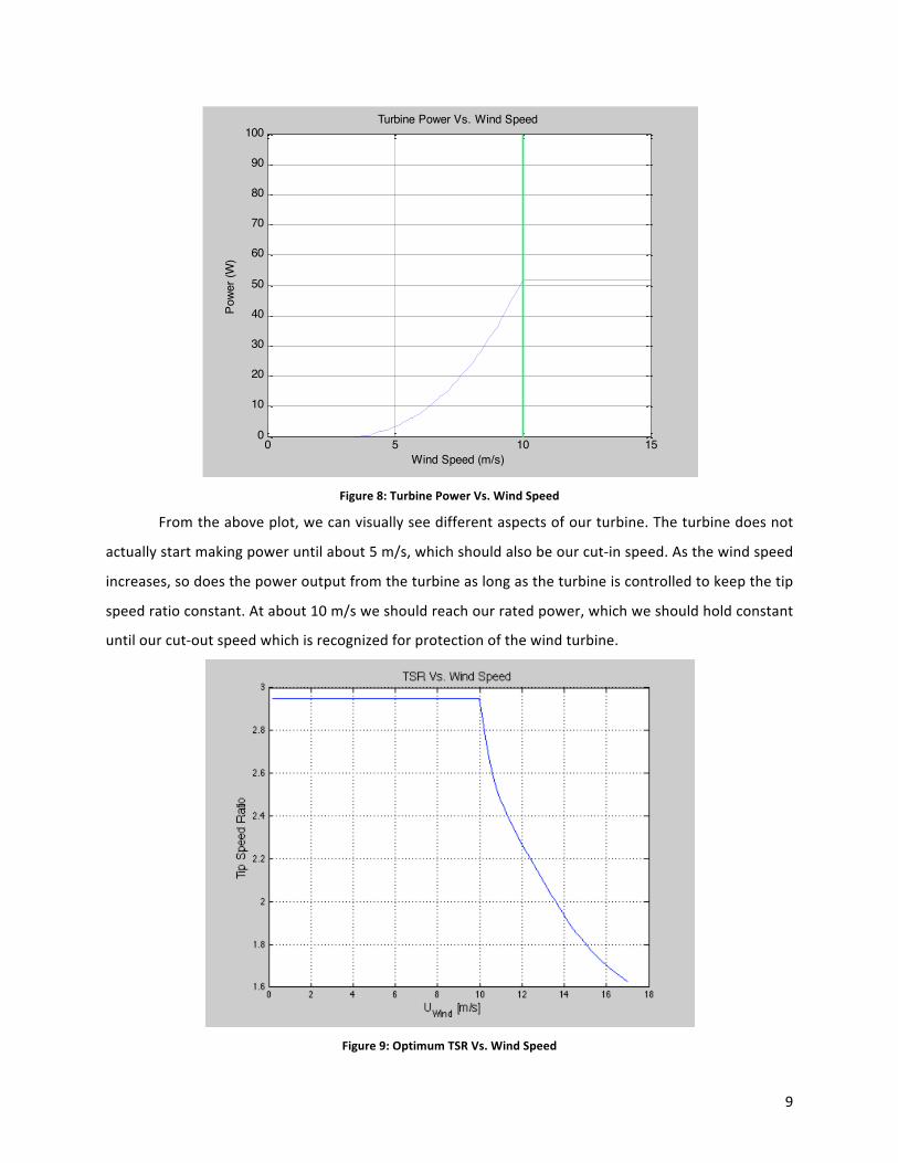
Figure 8: Turbine Power Vs. Wind Speed
From the above plot, we can visually see different aspects of our turbine. The turbine does not
actually start making power until about 5 m/s, which should also be our cut-‐in speed. As the wind speed
increases, so does the power output from the turbine as long as the turbine is controlled to keep the tip
speed ratio constant. At about 10 m/s we should reach our rated power, which we should hold constant
until our cut-‐out speed which is recognized for protection of the wind turbine.
0
10
20
30
40
50
60
70
80
90
Powe
r (W
)
Figure 9: Optimum TSR Vs. Wind Speed
9
Referring to the above figure, the optimum tip speed ratio for our wind turbine was about 3.
This told us that we should regulate the turbine speed to maintain this constant tip speed ratio in order
to maximize our power output especially in lower wind speeds [1]. With this knowledge in hand it was
then important to review the power characteristics we could expect from varying wind speeds.
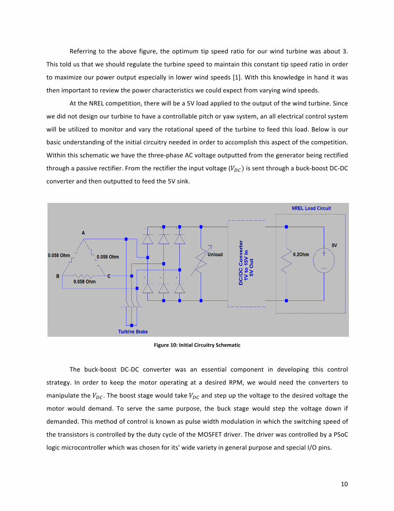
At the NREL competition, there will be a 5V load applied to the output of the wind turbine. Since
we did not design our turbine to have a controllable pitch or yaw system, an all electrical control system
will be utilized to monitor and vary the rotational speed of the turbine to feed this load. Below is our
basic understanding of the initial circuitry needed in order to accomplish this aspect of the competition.
Within this schematic we have the three-‐phase AC voltage outputted from the generator being rectified
through a passive rectifier. From the rectifier the input voltage (𝑉 c) is sent through a buck-‐boost DC-‐DC
converter and then outputted to feed the 5V sink.
Figure 10: Initial Circuitry Schematic
The buck-‐boost DC-‐DC converter was an essential component in developing this control
strategy. In order to keep the motor operating at a desired RPM, we would need the converters to
manipulate the 𝑉 c . The boost stage would take 𝑉 c and step up the voltage to the desired voltage the
motor would demand. To serve the same purpose, the buck stage would step the voltage down if
demanded. This method of control is known as pulse width modulation in which the switching speed of
the transistors is controlled by the duty cycle of the MOSFET driver. The driver was controlled by a PSoC
logic microcontroller which was chosen for its' wide variety in general purpose and special I/O pins.
10
Another component that was pertinent in our control system was the ability to measure the
current after the rectifier and after each stage of the buck-‐boost converter. Using voltage dividers and
current sensors, it would be possible to calculate the power in and out of the converter stages, a
common method in controlling and regulating optimum power. All of these components were designed
to be modular so that if one of the stages fails then it could be easily replaced. In dangerous high wind
situations, many larger turbines utilize a mechanical brake to stop the shaft of the turbine. For our small
wind turbine we will be using an electrical braking system as it is more efficient for us. By having a relay
incorporated in our system we would connect the voltage output of the generator to the dump load
upo triggering it. Once triggered the relay will be activated and switch to the low resistance dump load.
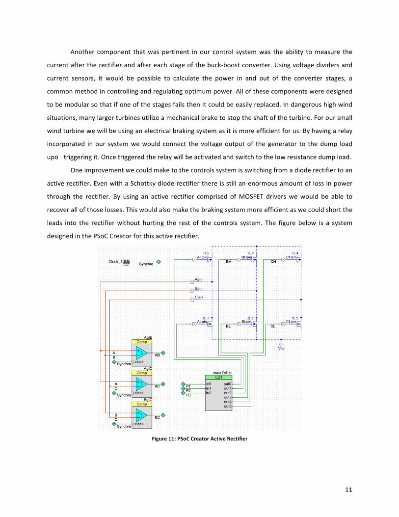
One improvement we could make to the controls system is switching from a diode rectifier to an
active rectifier. Even with a Schottky diode rectifier there is still an enormous amount of loss in power
through the rectifier. By using an active rectifier comprised of MOSFET drivers we would be able to
recover all of those losses. This would also make the braking system more efficient as we could short the
leads into the rectifier without hurting the rest of the controls system. The figure below is a system
designed in the PSoC Creator for this active rectifier.
Figure 11: PSoC Creator Active Rectifier
11
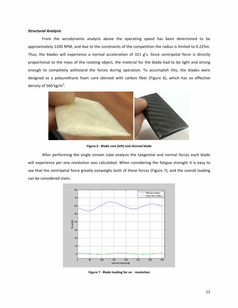
Structural Analysis
From the aerodynamic analysis above the operating speed has been determined to be
approximately 1200 RPM, and due to the constraints of the competition the radius is limited to 0.225m.
Thus, the blades will experience a normal acceleration of 321 g’s. Since centripetal force is directly
proportional to the mass of the rotating object, the material for the blade had to be light and strong
enough to completely withstand the forces during operation. To accomplish this, the blades were
designed as a polyurethane foam core skinned with carbon fiber (Figure 6), which has an effective
density of 560 kg/m3 .
Figure 6 -‐ Blade core (left) and skinned blade
After performing the single stream tube analysis the tangential and normal forces each blade
will experience per one revolution was calculated. When considering the fatigue strength it is easy to
see that the centripetal force greatly outweighs both of these forces (Figure 7), and the overall loading
can be considered static.
Figure 7 -‐ Blade loading for on revolution
12
With this in mind, a FEA analysis was performed modeling the blade as an idealized cantilever
beam experiencing 321 g’s, which resulted in a maximum bending moment at the connection of
3.35Nm. To verify these results, a four-‐point bending test was performed and the blade failed at a
bending moment of approximately 15Nm. Then in order to ensure that strut-‐to-‐blade connection was
robust enough, a force of 200N was hung from this point. From these results, it was determined that the
blades should be able to withstand the forces due to operation.
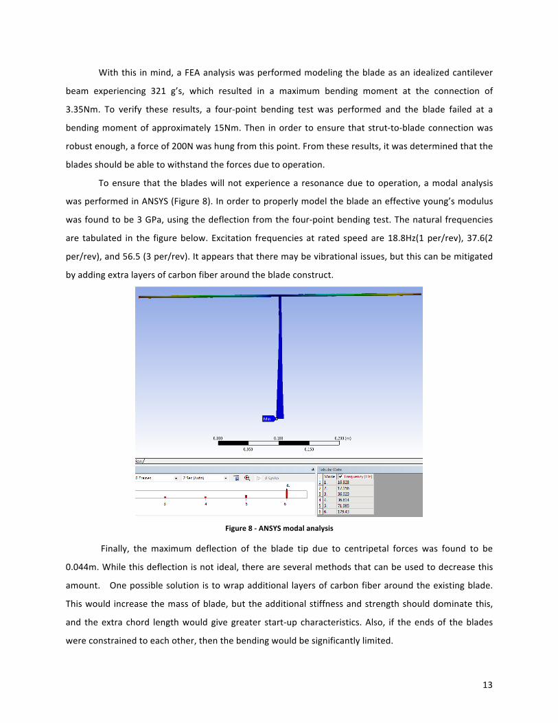
To ensure that the blades will not experience a resonance due to operation, a modal analysis
was performed in ANSYS (Figure 8). In order to properly model the blade an effective young’s modulus
was found to be 3 GPa, using the deflection from the four-‐point bending test. The natural frequencies
are tabulated in the figure below. Excitation frequencies at rated speed are 18.8Hz(1 per/rev), 37.6(2
per/rev), and 56.5 (3 per/rev). It appears that there may be vibrational issues, but this can be mitigated
by adding extra layers of carbon fiber around the blade construct.
Figure 8 -‐ ANSYS modal analysis
Finally, the maximum deflection of the blade tip due to centripetal forces was found to be
0.044m. While this deflection is not ideal, there are several methods that can be used to decrease this
amount. One possible solution is to wrap additional layers of carbon fiber around the existing blade.
This would increase the mass of blade, but the additional stiffness and strength should dominate this,
and the extra chord length would give greater start-‐up characteristics. Also, if the ends of the blades
were constrained to each other, then the bending would be significantly limited.
13
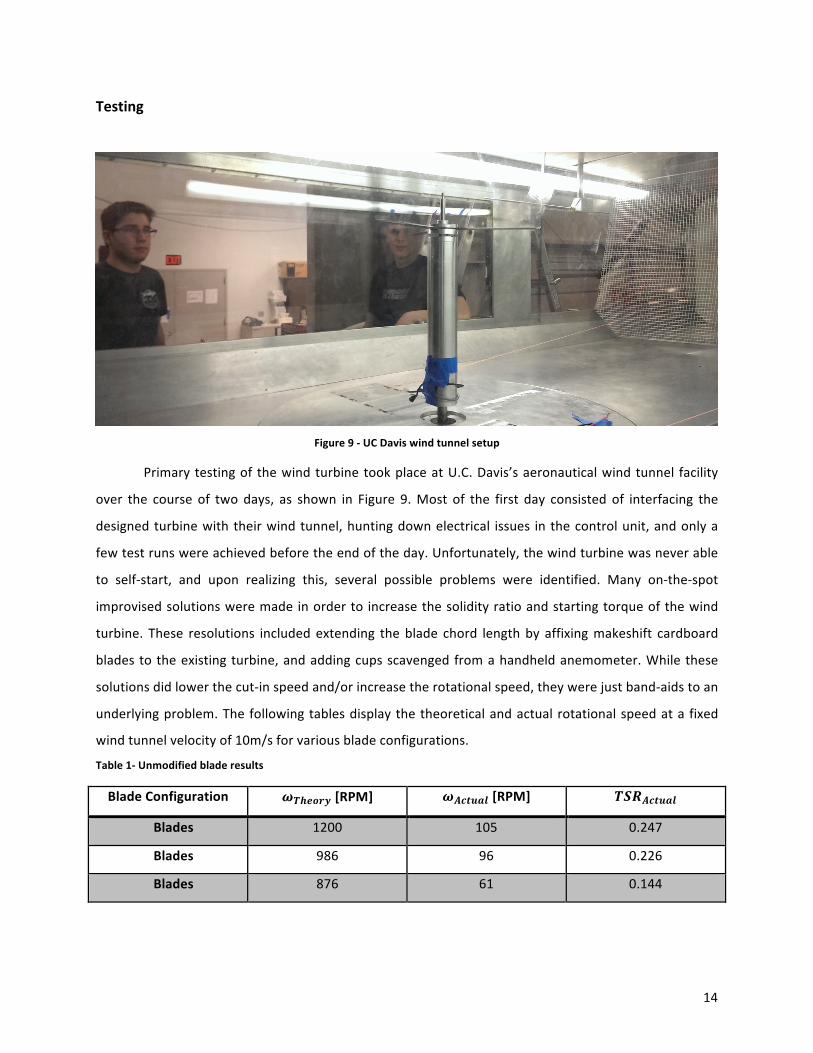
Testing
Figure 9 -‐ UC Davis wind tunnel setup
Primary testing of the wind turbine took place at U.C. Davis’s aeronautical wind tunnel facility
over the course of two days, as shown in Figure 9. Most of the first day consisted of interfacing the
designed turbine with their wind tunnel, hunting down electrical issues in the control unit, and only a
few test runs were achieved before the end of the day. Unfortunately, the wind turbine was never able
to self-‐start, and upon realizing this, several possible problems were identified. Many on-‐the-‐spot
improvised solutions were made in order to increase the solidity ratio and starting torque of the wind
turbine. These resolutions included extending the blade chord length by affixing makeshift cardboard
blades to the existing turbine, and adding cups scavenged from a handheld anemometer. While these
solutions did lower the cut-‐in speed and/or increase the rotational speed, they were just band-‐aids to an
underlying problem. The following tables display the theoretical and actual rotational speed at a fixed
wind tunnel velocity of 10m/s for various blade configurations.
Table 1-‐ Unmodified blade results
Blade Configuration 𝝎𝑻𝒉𝒆𝒐𝒓𝒚 [RPM] 𝝎𝑨𝒄𝒕𝒖𝒂𝒍 [RPM] 𝑻𝑺𝑹𝑨𝒄𝒕𝒖𝒂𝒍
Blades 1200 105 0.247
Blades 986 96 0.226
Blades 876 61 0.144
14
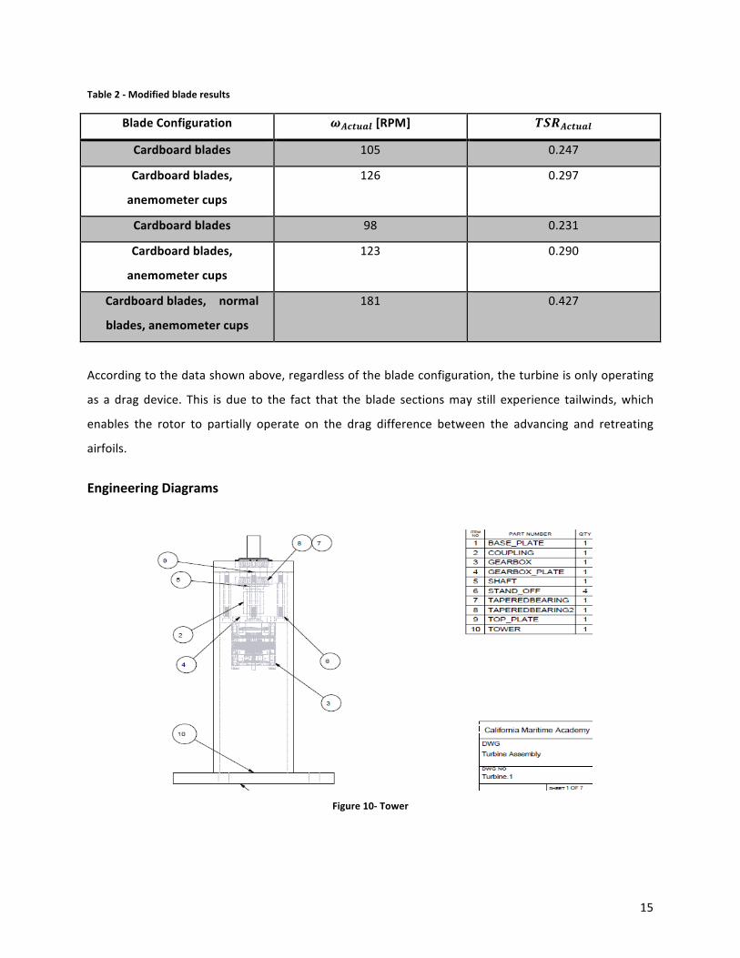
Table 2 -‐ Modified blade results
Blade Configuration 𝝎𝑨𝒄𝒕𝒖𝒂𝒍 [RPM] 𝑻𝑺𝑹𝑨𝒄𝒕𝒖𝒂𝒍
Cardboard blades 105 0.247
Cardboard blades,
anemometer cups
126 0.297
Cardboard blades 98 0.231
Cardboard blades,
anemometer cups
123 0.290
Cardboard blades, normal
blades, anemometer cups
181 0.427
According to the data shown above, regardless of the blade configuration, the turbine is only operating
as a drag device. This is due to the fact that the blade sections may still experience tailwinds, which
enables the rotor to partially operate on the drag difference between the advancing and retreating
airfoils.
Engineering Diagrams
Figure 10-‐ Tower
15

Figure 10 shows the assembly for the tower, which is comprised of several different
subcomponents. To simplify the design all of the components were connected in a concentric
linear fashion as shown below.
Figure 11 – Gear train assembly
Figure 11 above shows the VAWT gear train assembly, all of which would be contained inside the tower.
The turbine blades attach to the left side of the picture through the hub pieces, shown below in FIGURE,
while the generator attaches through a coupling to the 5:1 planetary gearbox on the right side.
Standoffs were used in the design in order to facilitate easier removal of the gearbox plate from the top
plate. Tapered roller bearings were used in the design to axially lock the pieces of the assembly.
Figure 12 -‐ Hub drawing
16
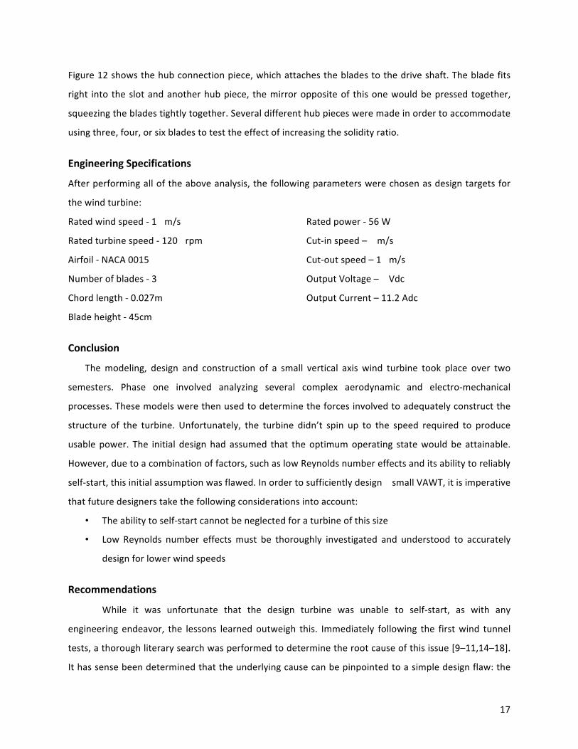
Figure 12 shows the hub connection piece, which attaches the blades to the drive shaft. The blade fits
right into the slot and another hub piece, the mirror opposite of this one would be pressed together,
squeezing the blades tightly together. Several different hub pieces were made in order to accommodate
using three, four, or six blades to test the effect of increasing the solidity ratio.
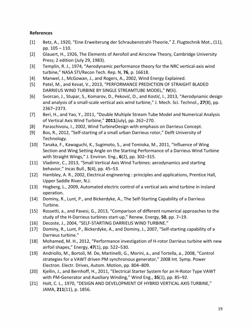
Engineering Specifications
After performing all of the above analysis, the following parameters were chosen as design targets for
the wind turbine:
Rated wind speed -‐ 1 m/s Rated power -‐ 56 W
Rated turbine speed -‐ 120 rpm Cut-‐in speed – m/s
Airfoil -‐ NACA 0015 Cut-‐out speed – 1 m/s
Number of blades -‐ 3 Output Voltage – Vdc
Chord length -‐ 0.027m Output Current – 11.2 Adc
Blade height -‐ 45cm
Conclusion
The modeling, design and construction of a small vertical axis wind turbine took place over two
semesters. Phase one involved analyzing several complex aerodynamic and electro-‐mechanical
processes. These models were then used to determine the forces involved to adequately construct the
structure of the turbine. Unfortunately, the turbine didn’t spin up to the speed required to produce
usable power. The initial design had assumed that the optimum operating state would be attainable.
However, due to a combination of factors, such as low Reynolds number effects and its ability to reliably
self-‐start, this initial assumption was flawed. In order to sufficiently design small VAWT, it is imperative
that future designers take the following considerations into account:
• The ability to self-‐start cannot be neglected for a turbine of this size
• Low Reynolds number effects must be thoroughly investigated and understood to accurately
design for lower wind speeds
Recommendations
While it was unfortunate that the design turbine was unable to self-‐start, as with any
engineering endeavor, the lessons learned outweigh this. Immediately following the first wind tunnel
tests, a thorough literary search was performed to determine the root cause of this issue [9–11,14–18].
It has sense been determined that the underlying cause can be pinpointed to a simple design flaw: the
17

turbine was not designed for start up. In particular, the combination of small scale, low wind speeds,
and low Reynolds numbers results in a wildly fluctuating angle of attack, which frequently pushes the
airfoils far beyond the point of stall. Thus, it is important to include the strong Reynolds number
variations to account for performance degradation. For small VAWTS, it seems highly inaccurate to rely
o the rated 𝐶P for off design conditions [9].
Solutions for the start-‐up problem generally have to do with improving airfoil performance for
low Reynolds numbers or finding other ways of increasing torque. The following suggestions are possible
ways to increase small VAWT self-‐starting performance:
• One way to circumvent a VAWT’s inability to reliably self-‐start would be to manually spin the
turbine up to operating speed. This can be accomplished by motorizing the generator[13,19,20].
In theory, this will allow the turbine to act as a lift-‐based device once the 𝐶P becomes positive.
• A hybrid VAWT can be created by attaching a drag based auxiliary rotor to the turbine [21].
While this is an effective mean of creating additional starting torque, several disadvantages also
exist. Mainly, this configuration can lead to an inefficient design because it is difficult to match
the optimum TSR of the drag device with the lift device.
• Boundary layer trips can be affixed to the blades in order to force the flow to become turbulent
before the point of separation. This relatively cheap and simple solution does create extra drag
and the optimum position is difficult to determine.
All things being created equal, it should be recognized that when designing a VAWT for start-‐up
could only be accomplished by sacrificing the maximum performance. Thus, it is important for the
designer to heavily weigh all of the options available to them before heading down one or the other
paths of development.
Acknowledgements
This project wouldn’t have been accomplished with out help, and we would like to give special
acknowledgement to:
• Our advisor Dr. Tom Nordenholz for without you this project would have never been completed.
• Professor Stan Hitchcock for bestowing his endless supply of machining experience upon us.
• Professor Michael Strange for entertaining our wildest ideas and always providing
encouragement.
• Owen Hurley, former CMA grad and current UCD graduate student, and Raymond Chow, PhD. of
University of California, Davis for graciously lending us their time, expertise, and wind tunnel.
18
References
[1] Betz, A., 1920, “Eine Erweiterung der Schraubenstrahl-‐Theorie,” Z. Flugtechnik Mot., (11),pp. 105 – 110.
[2] Glauert, H., 1926, The Elements of Aerofoil and Airscrew Theory, Cambridge UniversityPress; 2 edition (July 29, 1983).
[3] Templin, R. J., 1974, “Aerodynamic performance theory for the NRC vertical-‐axis windturbine,” NASA STI/Recon Tech. Rep. N, 76, p. 16618.
[4] Manwel, J., McGowan, J., and Rogers, A., 2002, Wind Energy Explained.[5] Patel, M., and Kevat, V., 2013, “PERFORMANCE PREDICTION OF STRAIGHT BLADED
DARRIEUS WIND TURBINE BY SINGLE STREAMTUBE MODEL,” IV(Ii).[6] Svorcan, J., Stupar, S., Komarov, D., Peković, O., and Kostić, I., 2013, “Aerodynamic design
and analysis of a small-‐scale vertical axis wind turbine,” J. Mech. Sci. Technol., 27(8), pp.2367–2373.
[7] Beri, H., and Yao, Y., 2011, “Double Multiple Stream Tube Model and Numerical Analysisof Vertical Axis Wind Turbine,” 2011(July), pp. 262–270.
[8] Paraschivoiu, I., 2002, Wind TurbineDesign with emphasis on Darrieus Concept.[9] Bos, R., 2012, “Self-‐starting of a small urban Darrieus rotor,” Delft University of
Technology.[10] Tanaka, F., Kawaguchi, K., Sugimoto, S., and Tomioka, M., 2011, “Influence of Wing
Section and Wing Setting Angle on the Starting Performance of a Darrieus Wind Turbinewith Straight Wings,” J. Environ. Eng., 6(2), pp. 302–315.
[11] Vladimir, C., 2013, “Small Vertical Axis Wind Turbines: aerodynamics and startingbehavior,” Incas Bull., 5(4), pp. 45–53.
[12] Hambley, A. R., 2002, Electrical engineering : principles and applications, Prentice Hall,Upper Saddle River, N.J.
[13] Hogberg, L., 2009, Automated electric control of a vertical axis wind turbine in inslandoperation.
[14] Dominy, R., Lunt, P., and Bickerdyke, A., The Self-‐Starting Capability of a DarrieusTurbine.
[15] Rossetti, a., and Pavesi, G., 2013, “Comparison of different numerical approaches to thestudy of the H-‐Darrieus turbines start-‐up,” Renew. Energy, 50, pp. 7–19.
[16] Decoste, J., 2004, “SELF-‐STARTING DARRIEUS WIND TURBINE.”[17] Dominy, R., Lunt, P., Bickerdyke, A., and Dominy, J., 2007, “Self-‐starting capability of a
Darrieus turbine.”[18] Mohamed, M. H., 2012, “Performance investigation of H-‐rotor Darrieus turbine with new
airfoil shapes,” Energy, 47(1), pp. 522–530.[19] Andriollo, M., Bortoli, M. De, Martinelli, G., Morini, a., and Tortella, a., 2008, “Control
strategies for a VAWT driven PM synchronous generator,” 2008 Int. Symp. PowerElectron. Electr. Drives, Autom. Motion, pp. 804–809.
[20] Kjellin, J., and Bernhoff, H., 2011, “Electrical Starter System for an H-‐Rotor Type VAWTwith PM-‐Generator and Auxiliary Winding,” Wind Eng., 35(1), pp. 85–92.
[21] Holt, C. L., 1970, “DESIGN AND DEVELOPMENT OF HYBRID VERTICAL AXIS TURBINE,”JAMA, 211(11), p. 1856.
19

20