sm1000 videographic recorder - abb group · pdf filesm1000 videographic recorder contents...
TRANSCRIPT

User Guide IM/SM1000 Rev. O
SM1000Videographic Recorder

The CompanyWe are an established world force in the design and manufacture of measurement products for industrial process control, flow measurement, gas and liquid analysis and environmental applications.
As a part of ABB, a world leader in process automation technology, we offer customers application expertise, service and support worldwide.
We are committed to teamwork, high quality manufacturing, advanced technology and unrivalled service and support.
The quality, accuracy and performance of the Company’s products result from over 100 years experience, combined with a continuous program of innovative design and development to incorporate the latest technology.
EN ISO 9001:2000
Cert. No. Q 05907
EN 29001 (ISO 9001)
Lenno, Italy – Cert. No. 9/90A
Stonehouse, U.K.
Electrical SafetyThis equipment complies with the requirements of CEI/IEC 61010-1:2001-2 'Safety Requirements for Electrical Equipment for Measurement, Control and Laboratory Use'. If the equipment is used in a manner NOT specified by the Company, the protection provided by the equipment may be impaired.
SymbolsOne or more of the following symbols may appear on the equipment labelling:
Warning – Refer to the manual for instructions Direct current supply only
Caution – Risk of electric shock Alternating current supply only
Protective earth (ground) terminal Both direct and alternating current supply
Earth (ground) terminalThe equipment is protected through double insulation
Information in this manual is intended only to assist our customers in the efficient operation of our equipment. Use of this manual for any other purpose is specifically prohibited and its contents are not to be reproduced in full or part without prior approval of the Technical Publications Department.
Health and Safety
To ensure that our products are safe and without risk to health, the following points must be noted:
1. The relevant sections of these instructions must be read carefully before proceeding.
2. Warning labels on containers and packages must be observed.
3. Installation, operation, maintenance and servicing must only be carried out by suitably trained personnel and in accordance with the information given.
4. Normal safety precautions must be taken to avoid the possibility of an accident occurring when operating in conditions of high pressure and/or temperature.
5. Chemicals must be stored away from heat, protected from temperature extremes and powders kept dry. Normal safe handling procedures must be used.
6. When disposing of chemicals ensure that no two chemicals are mixed.
Safety advice concerning the use of the equipment described in this manual or any relevant hazard data sheets (where applicable) may be obtained from the Company address on the back cover, together with servicing and spares information.
SM1000Videographic Recorder Contents
IM/SM1000–EN Rev. O 1
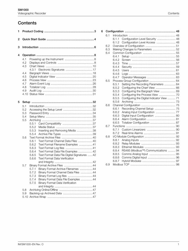
Contents
1 Product Coding ...............................................................3
2 Quick Start Guide ............................................................4
3 Introduction .....................................................................6
4 Operation .........................................................................84.1 Powering up the Instrument .....................................84.2 Displays and Controls ..............................................84.3 Chart Views ...........................................................10
4.3.1 Electronic Signatures ..................................174.4 Bargraph Views ......................................................184.5 Digital Indicator View ..............................................204.6 Process View .........................................................234.7 Alarm Event Log .....................................................264.8 Totalizer Log ..........................................................284.9 Audit Log ...............................................................304.10 Status View ............................................................31
5 Setup .............................................................................325.1 Introduction ............................................................325.2 Accessing the Setup Level .....................................325.3 Password Entry ......................................................345.4 Setup Menu ...........................................................355.5 Archiving ................................................................37
5.5.1 Card Compatibility ......................................375.5.2 Media Status ..............................................375.5.3 Inserting and Removing Media ....................385.5.4 Archive File Types .......................................39
5.6 Text Format Archive Files .......................................405.6.1 Text Format Channel Data Files ..................405.6.2 Text Format Filename Examples .................415.6.3 Text Format Log files ..................................415.6.4 Text Format Data File Examples ..................425.6.5 Text Format Data File Digital Signatures ......425.6.6 Text Format Data Verification
and Integrity ................................................425.7 Binary Format Archive Files ....................................44
5.7.1 Binary Format Archive Filenames ................445.7.2 Binary Format Channel Data Files ...............445.7.3 Binary Format Log files ...............................445.7.4 Binary Format Data File Examples ...............445.7.5 Binary Format Data Verification
and Integrity ................................................445.8 Archiving Online/Offline ..........................................475.9 Backing-up Archived Data .....................................475.10 Archive Wrap .........................................................47
6 Configuration ................................................................ 486.1 Introduction ........................................................... 48
6.1.1 Configuration Level Security ....................... 486.1.2 Configuration Level Access ........................ 48
6.2 Overview of Configuration ...................................... 516.3 Making Changes to Parameters ............................. 526.4 Common Configuration ......................................... 55
6.4.1 Setup ......................................................... 556.4.2 Screen ....................................................... 566.4.3 Time ........................................................... 576.4.4 Security ...................................................... 596.4.5 Users ......................................................... 616.4.6 Logs ........................................................... 636.4.7 Operator Messages .................................... 63
6.5 Process Group Configuration ................................. 646.5.1 Setting the Recording Parameters .............. 646.5.2 Configuring the Chart View ......................... 666.5.3 Configuring the Bargraph View ................... 696.5.4 Configuring the Process View ..................... 706.5.5 Configuring the Digital Indicator View .......... 716.5.6 Archiving .................................................... 73
6.6 Channel Configuration ........................................... 756.6.1 Recording Channel Setup .......................... 756.6.2 Analog Input Configuration ......................... 776.6.3 Digital Input Configuration .......................... 806.6.4 Alarm Configuration .................................... 816.6.5 Totalizer Configuration ................................ 87
6.7 Functions .............................................................. 906.7.1 Custom Linearizers .................................... 906.7.2 Real-time Alarms ........................................ 91
6.8 I/O Module Configuration ....................................... 926.8.1 Analog Inputs ............................................. 926.8.2 Relay Modules ........................................... 936.8.3 Ethernet Modules ....................................... 936.8.4 RS485 (Modbus™) Communications ......... 946.8.5 Comms Analog Input ................................. 956.8.6 Comms Digital Input ................................... 966.8.7 Hybrid Modules .......................................... 97
6.9 Modbus TCP ......................................................... 98
SM1000Videographic Recorder Contents
2 IM/SM1000–EN Rev. O
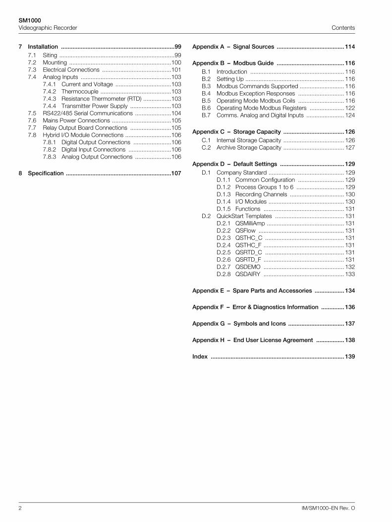
7 Installation .....................................................................997.1 Siting ......................................................................997.2 Mounting ..............................................................1007.3 Electrical Connections ..........................................1017.4 Analog Inputs .......................................................103
7.4.1 Current and Voltage ..................................1037.4.2 Thermocouple ...........................................1037.4.3 Resistance Thermometer (RTD) .................1037.4.4 Transmitter Power Supply .........................103
7.5 RS422/485 Serial Communications ......................1047.6 Mains Power Connections ....................................1057.7 Relay Output Board Connections .........................1057.8 Hybrid I/O Module Connections ............................106
7.8.1 Digital Output Connections .......................1067.8.2 Digital Input Connections ..........................1067.8.3 Analog Output Connections ......................106
8 Specification ................................................................107
Appendix A – Signal Sources ......................................... 114
Appendix B – Modbus Guide ......................................... 116B.1 Introduction ......................................................... 116B.2 Setting Up ............................................................ 116B.3 Modbus Commands Supported ........................... 116B.4 Modbus Exception Responses ............................ 116B.5 Operating Mode Modbus Coils ............................ 116B.6 Operating Mode Modbus Registers ..................... 122B.7 Comms. Analog and Digital Inputs ....................... 124
Appendix C – Storage Capacity ..................................... 126C.1 Internal Storage Capacity ..................................... 126C.2 Archive Storage Capacity ..................................... 127
Appendix D – Default Settings ....................................... 129D.1 Company Standard .............................................. 129
D.1.1 Common Configuration ............................ 129D.1.2 Process Groups 1 to 6 ............................. 129D.1.3 Recording Channels ................................. 130D.1.4 I/O Modules .............................................. 130D.1.5 Functions ................................................. 131
D.2 QuickStart Templates .......................................... 131D.2.1 QSMilliAmp ............................................... 131D.2.2 QSFlow .................................................... 131D.2.3 QSTHC_C ................................................ 131D.2.4 QSTHC_F ................................................. 131D.2.5 QSRTD_C ................................................ 131D.2.6 QSRTD_F ................................................. 131D.2.7 QSDEMO ................................................. 132D.2.8 QSDAIRY ................................................. 133
Appendix E – Spare Parts and Accessories .................. 134
Appendix F – Error & Diagnostics Information .............. 136
Appendix G – Symbols and Icons .................................. 137
Appendix H – End User License Agreement ................. 138
Index ................................................................................. 139
SM1000Videographic Recorder 1 Product Identification
IM/SM1000–EN Rev. O 3
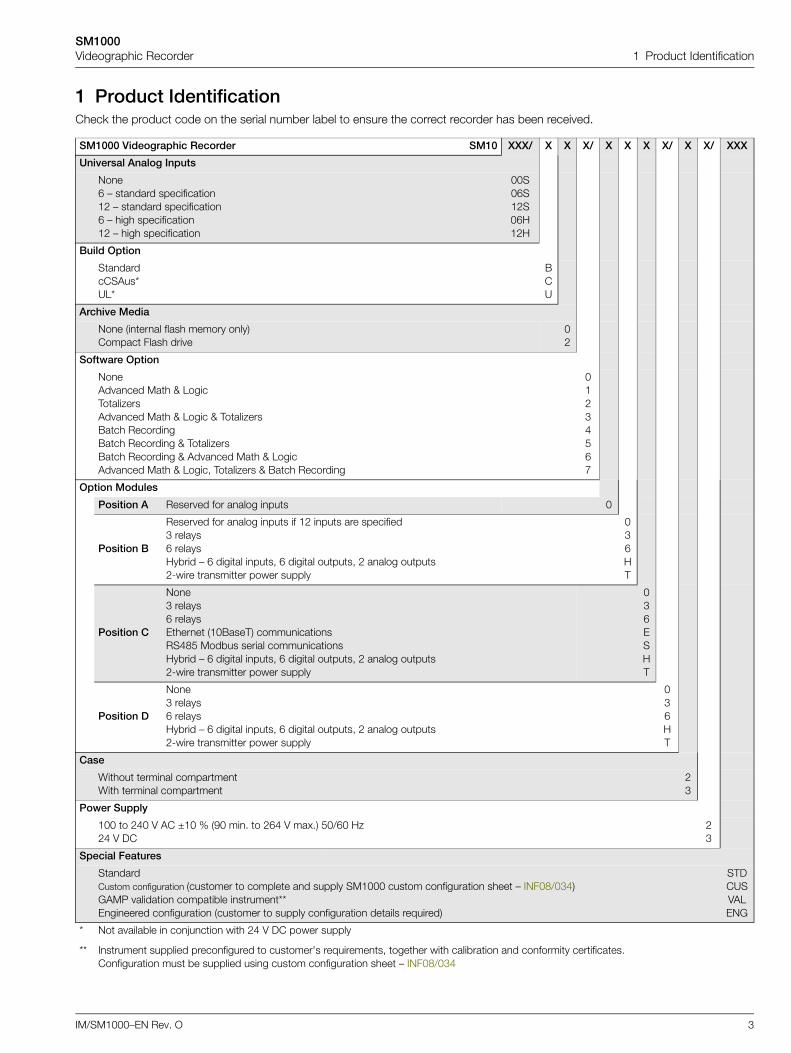
1 Product IdentificationCheck the product code on the serial number label to ensure the correct recorder has been received.
SM1000 Videographic Recorder SM10 XXX/ X X X/ X X X X/ X X/ XXX
Universal Analog Inputs
None6 – standard specification12 – standard specification6 – high specification12 – high specification
00S06S12S06H12H
Build Option
StandardcCSAus*UL*
BCU
Archive Media
None (internal flash memory only)Compact Flash drive
02
Software Option
NoneAdvanced Math & LogicTotalizersAdvanced Math & Logic & TotalizersBatch RecordingBatch Recording & TotalizersBatch Recording & Advanced Math & LogicAdvanced Math & Logic, Totalizers & Batch Recording
01234567
Option Modules
Position A Reserved for analog inputs 0
Position B
Reserved for analog inputs if 12 inputs are specified3 relays6 relaysHybrid – 6 digital inputs, 6 digital outputs, 2 analog outputs2-wire transmitter power supply
036HT
Position C
None3 relays6 relaysEthernet (10BaseT) communicationsRS485 Modbus serial communicationsHybrid – 6 digital inputs, 6 digital outputs, 2 analog outputs2-wire transmitter power supply
036ESHT
Position D
None3 relays6 relaysHybrid – 6 digital inputs, 6 digital outputs, 2 analog outputs2-wire transmitter power supply
036HT
Case
Without terminal compartmentWith terminal compartment
23
Power Supply
100 to 240 V AC ±10 % (90 min. to 264 V max.) 50/60 Hz24 V DC
23
Special Features
StandardCustom configuration (customer to complete and supply SM1000 custom configuration sheet – INF08/034)GAMP validation compatible instrument**Engineered configuration (customer to supply configuration details required)
STDCUSVALENG
*
**
Not available in conjunction with 24 V DC power supply
Instrument supplied preconfigured to customer's requirements, together with calibration and conformity certificates.Configuration must be supplied using custom configuration sheet – INF08/034
SM1000Videographic Recorder 2 Getting Started
4 IM/SM1000–EN Rev. O
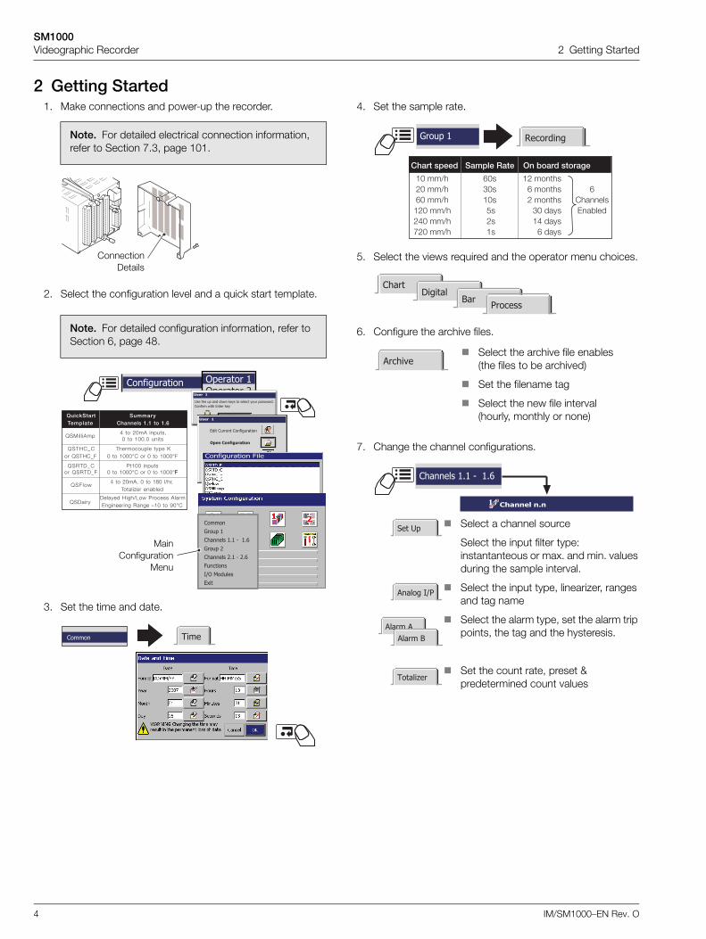
2 Getting Started1. Make connections and power-up the recorder.
2. Select the configuration level and a quick start template.
3. Set the time and date.
4. Set the sample rate.
5. Select the views required and the operator menu choices.
6. Configure the archive files.
7. Change the channel configurations.
Note. For detailed electrical connection information, refer to Section 7.3, page 101.
Note. For detailed configuration information, refer to Section 6, page 48.
ConnectionDetails
Configuration Operator 1Operator 2Operator 3Operator 4
User 1
Use the up and down keys to select your password.Confirm with Enter key
0000User 1
Edit Current Configuration
Open Configuration
New Configuration
Cancel
Disable Recording in Configuration
QuickStartTemplate
SummaryChannels 1.1 to 1.6
QSMilliAmp4 to 20mA inputs,0 to 100.0 units
QSTHC_Cor QSTHC_F
Thermocouple type K0 to 1000°C or 0 to 1000°F
QSRTD_Cor QSRTD_F
Pt100 inputs0 to 1000°C or 0 to 1000°FF
QSFlow4 to 20mA, 0 to 180 l/hr,
Totalizer enabled
QSDairyDelayed High/Low Process AlarmEngineering Range –10 to 90°C
Configuration File
CommonGroup 1Channels 1.1 - 1.6Group 2Channels 2.1 - 2.6FunctionsI/O ModulesExit
MainConfiguration
Menu
TimeCommon
Chart speed Sample Rate On board storage
10 mm/h 60s 12 months20 mm/h 30s 6 months 660 mm/h 10s 2 months Channels120 mm/h 5s 30 days Enabled240 mm/h 2s 14 days720 mm/h 1s 6 days
Group 1 Recording
ChartDigital
BarProcess
Archive Select the archive file enables
(the files to be archived)
Set the filename tag
Select the new file interval (hourly, monthly or none)
Channel n.n
Channels 1.1 - 1.6
Set Up
Analog I/P
Totalizer
Alarm AAlarm B
Select a channel source
Select the input filter type: instantanteous or max. and min. values during the sample interval.
Select the input type, linearizer, ranges and tag name
Select the alarm type, set the alarm trip points, the tag and the hysteresis.
Set the count rate, preset & predetermined count values
SM1000Videographic Recorder 2 Getting Started
IM/SM1000–EN Rev. O 5
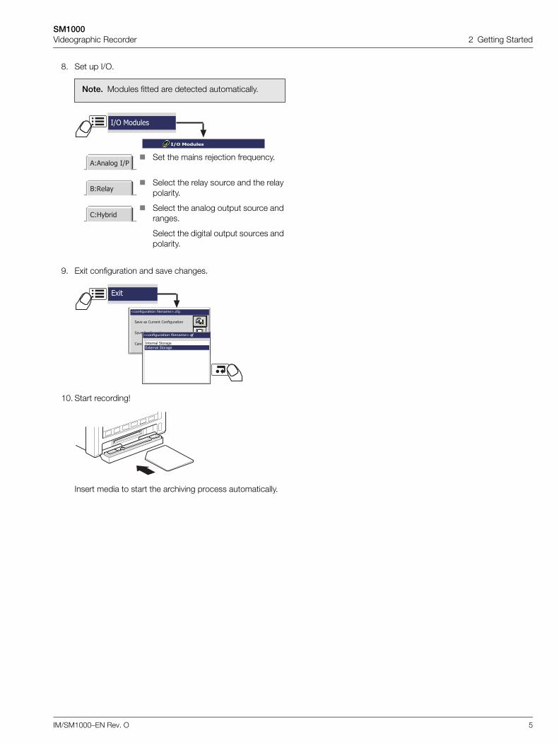
8. Set up I/O.
9. Exit configuration and save changes.
10. Start recording!
Insert media to start the archiving process automatically.
Note. Modules fitted are detected automatically.
I/O Modules
A:Analog I/P
B:Relay
C:Hybrid
I/O Modules
Set the mains rejection frequency.
Select the relay source and the relay polarity.
Select the analog output source and ranges.
Select the digital output sources and polarity.
<configuration filename>.cfg
Save as Current Configuration
Save Configuration
Cancel
Exit
<configuration filename>.cfg
Internal StorageExternal Storage
SM1000Videographic Recorder 3 Introduction
6 IM/SM1000–EN Rev. O
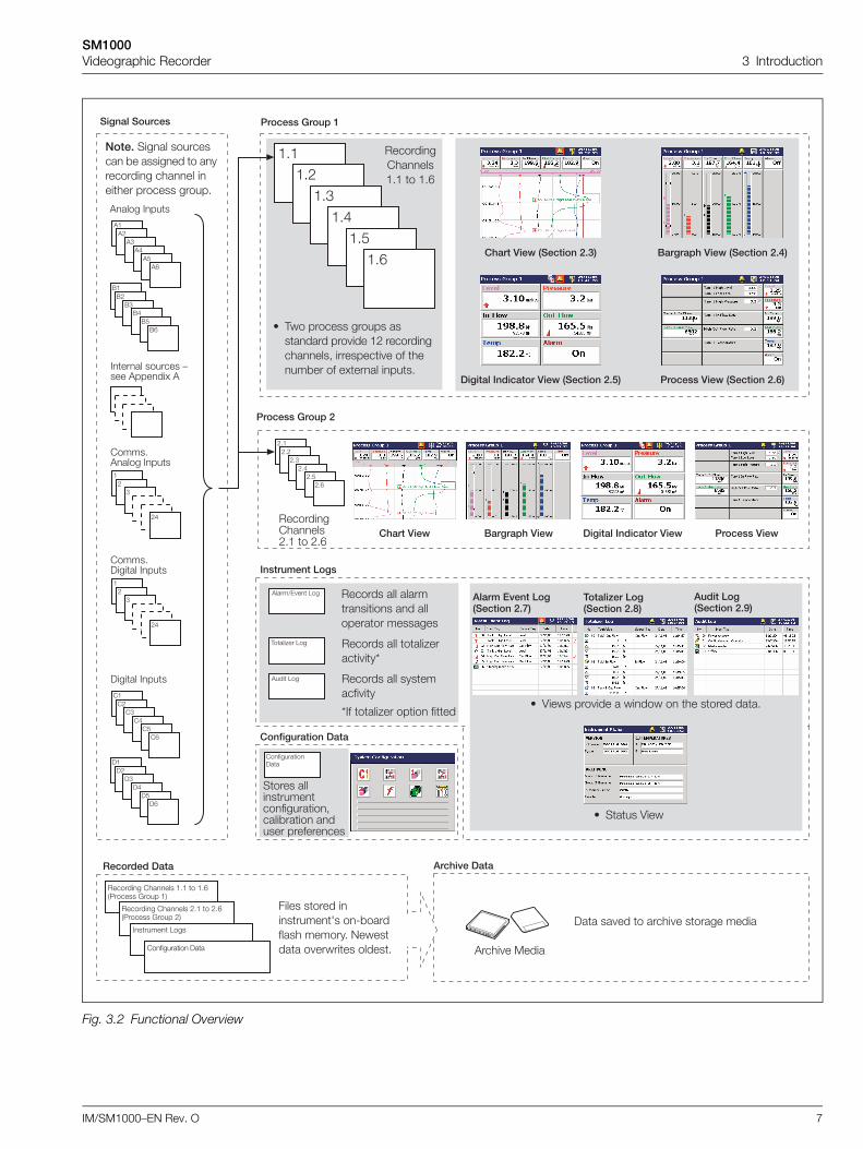
3 IntroductionFunctional Overview 12 Recording Channels as standard, divided into 2 Process Groups, each with 6 Recording Channels.
Two Alarms and one Totalizer (if Totalizer option is enabled) are assigned to each Recording Channel.
Signal sources derived from universal analog inputs, the Modbus serial link, optional digital inputs or internal analog and digitalsignals.
Any source can be assigned to any recording channel.
Data from assigned sources can be displayed in:
– Vertical or Horizontal Chart view format
– Vertical or Horizontal Bargraph view format
– Digital Indicator view format
– Process view format
Three instrument logs record alarm events, totalizer values (if totalizer option is enabled) and system/configuration changes.
Screen Capture facility – saves an image of any of the operator views to external archive media provided external archive mediawith sufficient free space is inserted in the instrument. It is not necessary for archiving to be 'online'.
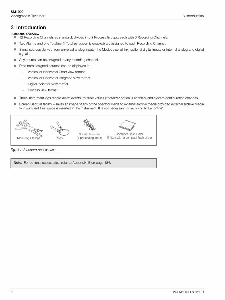
Fig. 3.1 Standard Accessories
Note. For optional accessories, refer to Appendix E on page 134.
��������� ��������� ��������
�� ��� ����� ���������� ����� ����
��� ���� ��� � ������ ����� ��� ��
SM1000Videographic Recorder 3 Introduction
IM/SM1000–EN Rev. O 7
Fig. 3.2 Functional Overview
����������� �
!"�!"!
!"#!"$
!"%!"&
������������
�"��"!
�"#�"$
�"%�"&
���������������"� � �"&
'�'!
'#'$
'%'&
'���� ����
(�(!
(#($
(%(&
�!
#
!$
�����"'���� ����
���!
�#�$
�%�&
)����� ����
��������������!"� � !"&
������������
���� ����� ��������� *� ������� � ���������� ����� ������ ������� �����"
����������
'���� � �����
)�� �� �� � ����� � ������ �����
�� ���������
+ ,�� ������� ������ �������� ��� ��� �! ��������������- ��������� � �� ����*�� �� �.���� ����"
'����/0 � 1�� ������� ��� ������������ �� ���������� ��������
,����2�� 1�� ������� ��� ����2����� ��3
'��� 1�� ������� ��� ��������� ��
����������� ��������!"
#�����$��� ��������%"
������� ��������&"
+ 4���� ��� ��� � ����� � �� ����� ���"
���'������
�������� ������ �"� � �"&�5������ 6���� ��
�������� ������ !"� � !"&�5������ 6���� !�
������ 1���
���������� )��
����� ����� �������7� �8*��������� ������" 9������� � ������� �����"
�!
#
!$
�����")����� ����
)�)!
)#)$
)%)&
����� ������� :��� '�����. '
+ ���� 4���
(�� ���')�* ��������+",'���)�* ��������-"
�� �������������)�* ��������." ������)�* ��������/"
,'���)�* (�� ���')�* �� �������������)�* ������)�*
����������)��
,��0� �����������
����� �������������������-����*���� ������ ����������
3�� ����2�� ���� ����
SM1000Videographic Recorder 4 Operation
8 IM/SM1000–EN Rev. O
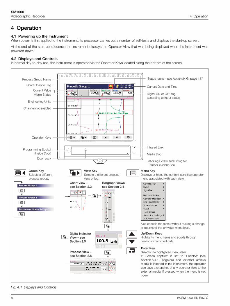
4 Operation4.1 Powering up the InstrumentWhen power is first applied to the instrument, its processor carries out a number of self-tests and displays the start-up screen.
At the end of the start-up sequence the instrument displays the Operator View that was being displayed when the instrument waspowered down.
4.2 Displays and ControlsIn normal day-to-day use, the instrument is operated via the Operator Keys located along the bottom of the screen.
Fig. 4.1 Displays and Controls
1��23)������� �� ����� �� ���.8����� � ���������� ��������� ��� ���� ���"
�����23������ � �������������� �����"
4�5��*�23�;�������� ��� ���� �� ������� ��������� ������ �������� ���"
)�*23������ � ������� ������� ��� �� ���"
�������������
������������
����������������������
,'���)�*6���������-
(�� ���')�*�6���������+
�� �������������)�*6���������.
������)�*6���������/
'��� ������ �� ��� ����� ��<�� � ������� ����� � �� ��� ���� ��� �� ��"
)��� 1��<����� )���
����� )�� �� ,���
5��������� ���<������� )����
������� 1�<
=��<�� ����� �� ���� ���,�����8� ��� ����
>������ ����
)����� >9 �� >�� ��-�������� � ��� ����
����� � ��*���
5������ 6���� 9���
���� ����� ,��
����� 4����'���� ����
0������� ?��
Status Icons – see Appendix G, page 137
Enter KeySelects the highlighted menu item.If 'Screen capture' is set to 'Enabled' (seeSection 6.4.1, page 55) and external archivemedia is inserted in the instrument, the operatorcan save a snapshot of any operator view to theexternal media, if pressed when the menu is notopen.
SM1000Videographic Recorder 4 Operation
IM/SM1000–EN Rev. O 9
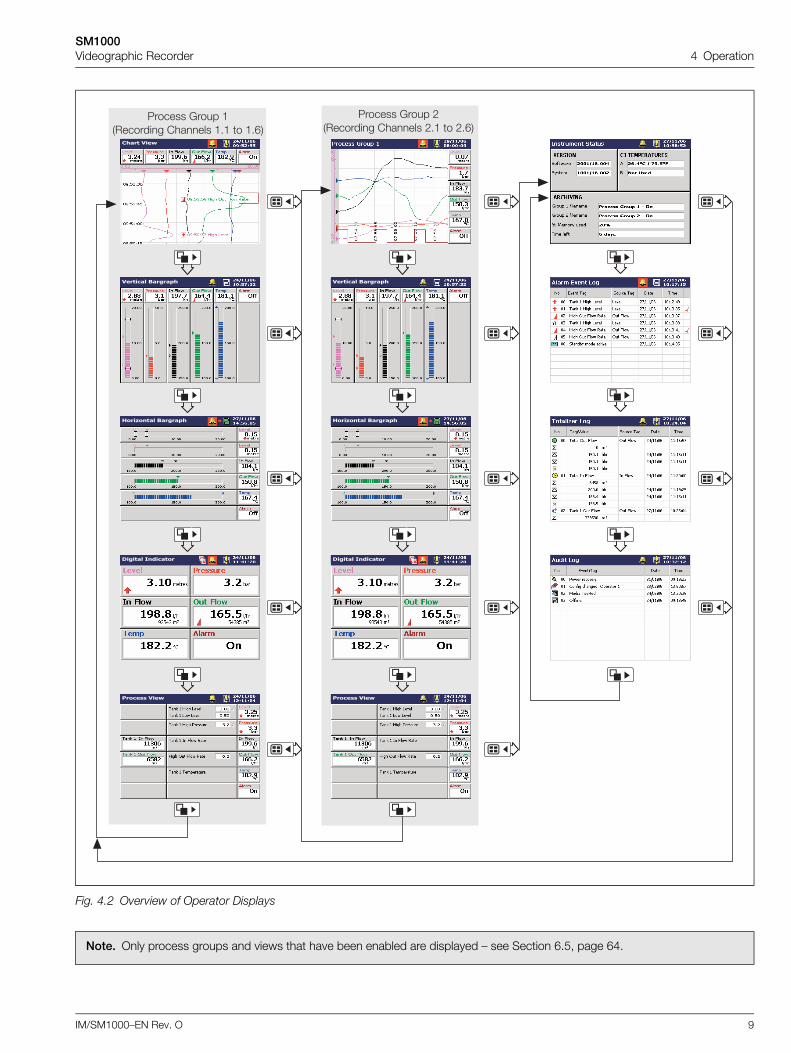
Fig. 4.2 Overview of Operator Displays
Note. Only process groups and views that have been enabled are displayed – see Section 6.5, page 64.
�����������������
�������������������
�����������������
�����������
5������ 6���� !��������� ������ !"� � !"&�
5������ 6���� ���������� ������ �"� � �"&�!��������
�����������������
�������������������
�����������������
�����������
SM1000Videographic Recorder 4 Operation
10 IM/SM1000–EN Rev. O
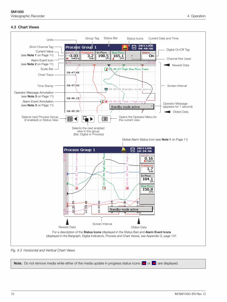
4.3 Chart Views
Fig. 4.3 Horizontal and Vertical Chart Views
Note. Do not remove media while either of the media update in progress status icons ( or ) are displayed.
9���� )�� >���� )������� ��� ��
9���� )��
>���� )��
���� ����� ,��
����� (��
6���� ,��?�� ���� (�� ���� ���� ����� )�� �� ,���
����� ��� ��,��� ����
���� ,����
)����� >/>�� ,��
����� 9� ?���
>������ ��������������� ��� � ������
������ �� �. ��*��� ��� � �� �����
�(��- )����� �� 5�������
������ �. 5������ 6������� ��*���� �� ���� 4���
>��� �� >������ ��� ����� ����� ���
Global Alarm Status Icon (see Note 1 on Page 11)
Current Value(see Note 1 on Page 11)
Operator Message Annotation(see Note 3 on Page 11)
Alarm Event Annotation(see Note 3 on Page 11)
Alarm Event Icon(see Note 2 on Page 11)
For a description of the Status Icons (displayed in the Status Bar) and Alarm Event Icons(displayed in the Bargraph, Digital Indicators, Process and Chart Views), see Appendix G, page 137.

SM1000Videographic Recorder 4 Operation
IM/SM1000–EN Rev. O 11
Note.
1. Current Values
The Current Value, shown on the digital indicators at either the top (vertical chart view) or right hand side (horizontal chartview) of the screen, is the latest instantaneous value and its update rate is not affected by the recording sample rate.
If the current value in the digital indicator is displayed in red, recording has been stopped for that channel – see Section 5.4,page 35 and see Section 6.6.1, page 75.
Traces are shown only when that particular channel is being recorded. When a channel is set to Stop, its trace continues tobe shown for up to one sample period.
2. Alarm Status
– Flashing red alarm event icon – alarm active and unacknowledged
– Continuous red alarm event icon – alarm active and acknowledged
If any alarm in any process group is active, the Global Alarm status icon ( ) is displayed in the status bar – see Fig. 4.3. Ifany active alarm in any process group is unacknowledged, the icon is surrounded by a red flashing border ( ).
3. Alarm Event and Operator Message Annotations
Alarm Event and Operator Message annotations are not shown on the chart unless enabled – see 'Chart Annotation' onpage 14 and see Section 6.5.2, page 66.
If Alarm event annotation is enabled and an alarm becomes active, a red alarm event icon surrounded by a channel coloredbox is displayed at the point at which the alarm occurred, together with the alarm time and tag, e.g.
If more than one alarm occurs in the same sample period:
– and the second alarm on a channel becomes active, its icon is added behind the first.
– and more than one operator message is active (max. six), a second icon is added behind the first.
– the new alarm event icons appear to the left of earlier icons.
– the time and tag of the oldest alarm (right-most icon) only is displayed.
4. Screen Capture
If 'Screen capture' is set to 'Enabled' in Common Configuration (see Section 6.4.1, page 55) and an external archive mediacard is inserted in the instrument, an image of any Chart, Bargraph, Digital Indicator, Process, Instrument Status, Audit Log,Alarm Log or Totalizer Log view can be saved to the external media by pressing the key whenever the Operator Menuis not open.
��������������� ������
SM1000Videographic Recorder 4 Operation
12 IM/SM1000–EN Rev. O
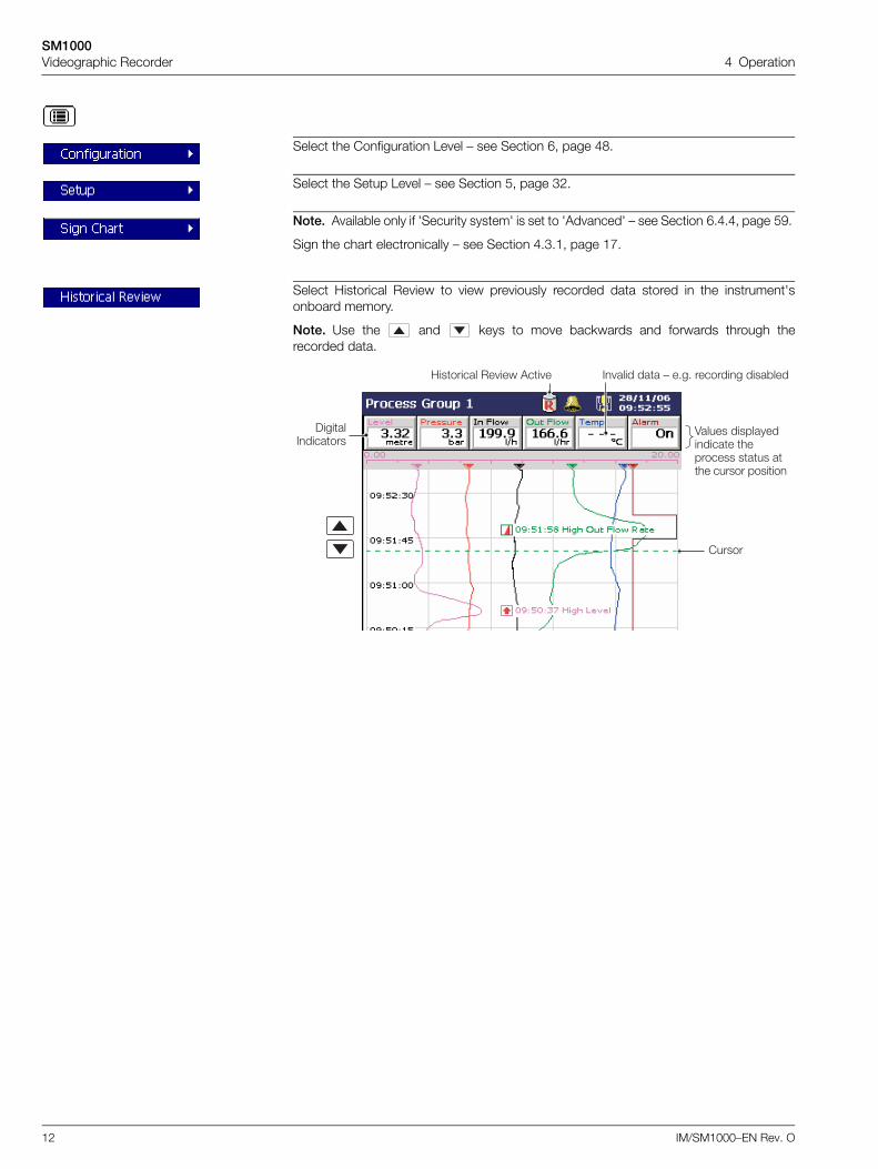
Select the Configuration Level – see Section 6, page 48.
Select the Setup Level – see Section 5, page 32.
Note. Available only if 'Security system' is set to 'Advanced' – see Section 6.4.4, page 59.
Sign the chart electronically – see Section 4.3.1, page 17.
Select Historical Review to view previously recorded data stored in the instrument'sonboard memory.
Note. Use the and keys to move backwards and forwards through therecorded data.
4����� ��������������� ��������� ���� ��� ������ ������
������
;�������� �� ��� '�� � � ���� ��� : �"�" �������� ����*���
)�������������
SM1000Videographic Recorder 4 Operation
IM/SM1000–EN Rev. O 13
Note.
While in Historical Review mode:
Recording of new data continues unless stopped from the Setup Menu – seeSection 5.4, page 35.
Invalid historical data (e.g. when recording has stopped) is denoted by '– – –' in thedigital indicator.
Where the trace at the cursor position represents more than one sample, theindicators flash between the maximum and minimum values of those samples.
Menu options remain active – allowing the screen interval to be changed, differentscales and channels to be selected, etc.
Operator messages generated are added to the alarm event log at the presenttime, not the time indicated by the cursor.
All data stored in the instrument's internal memory can be viewed.
The display can be scrolled back to the start of the oldest data.
Archiving to removable media does not occur but all data recorded in the internalmemory buffer during this time is archived on exiting Historical Review mode.
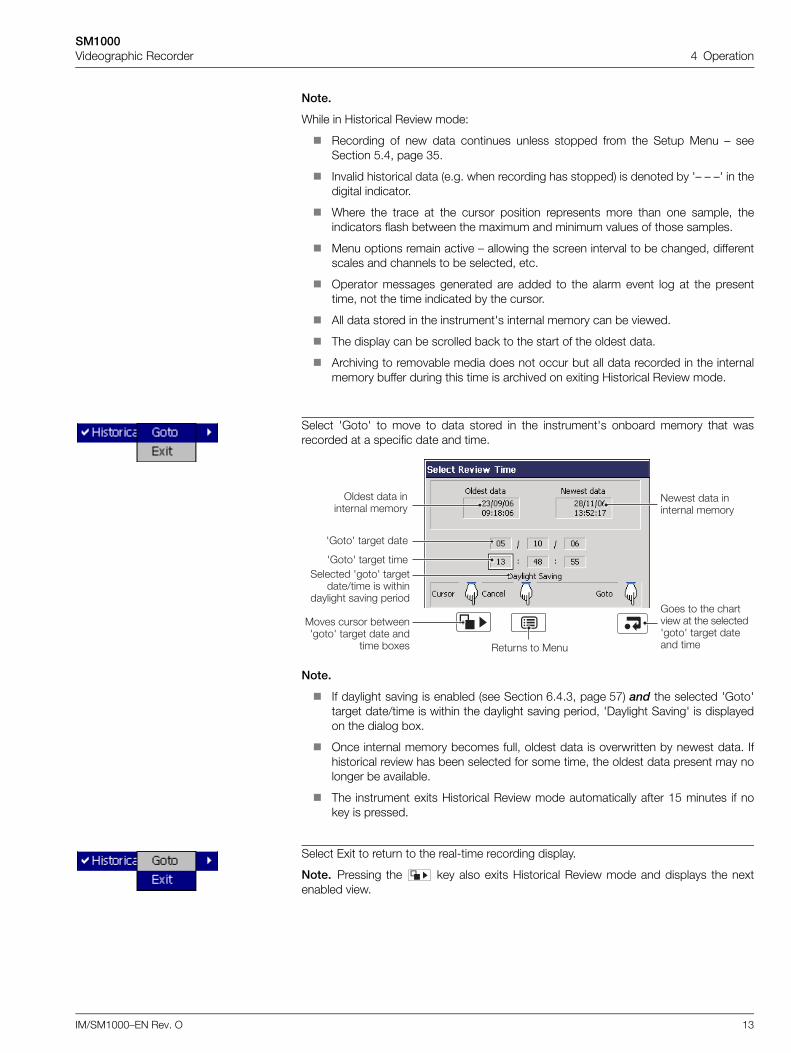
Select 'Goto' to move to data stored in the instrument's onboard memory that wasrecorded at a specific date and time.
Note.
If daylight saving is enabled (see Section 6.4.3, page 57) and the selected 'Goto'target date/time is within the daylight saving period, 'Daylight Saving' is displayedon the dialog box.
Once internal memory becomes full, oldest data is overwritten by newest data. Ifhistorical review has been selected for some time, the oldest data present may nolonger be available.
The instrument exits Historical Review mode automatically after 15 minutes if nokey is pressed.
Select Exit to return to the real-time recording display.
Note. Pressing the key also exits Historical Review mode and displays the nextenabled view.
>���� ��� ������ ������
9���� ��� ������ ������
76��7 ���� ���
76��7 ���� ���������� 7���7 ����
���/��� �� ����������� �� �� ������
����� � ���
�� �� ������ *����7���7 ���� ��� ��
��� *�.��
6��� � �� ���� ��� � �� �������7���7 ���� ����� ���
SM1000Videographic Recorder 4 Operation
14 IM/SM1000–EN Rev. O
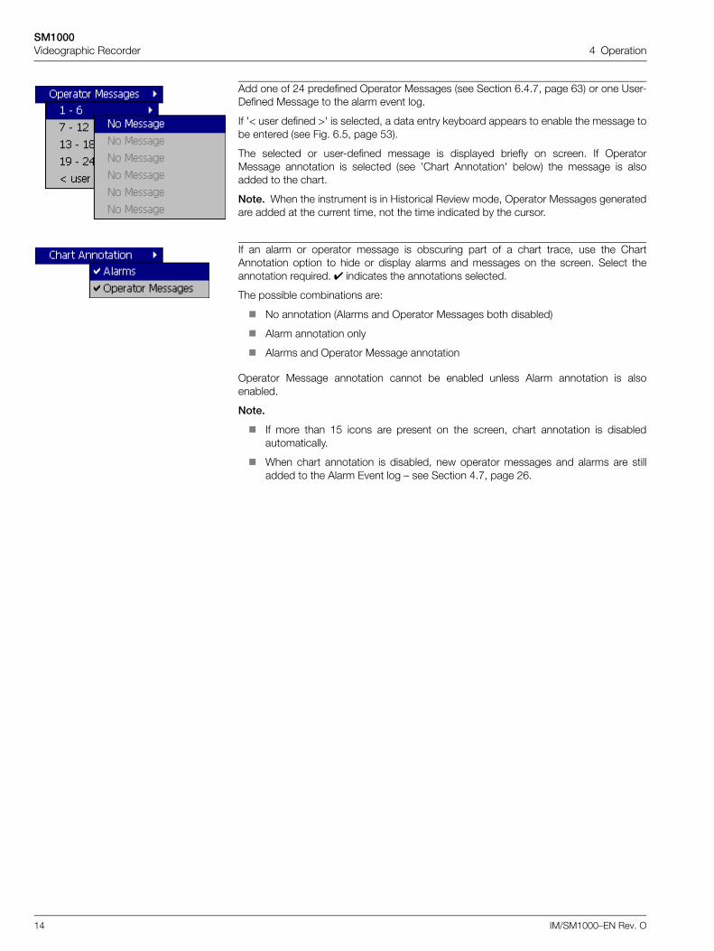
Add one of 24 predefined Operator Messages (see Section 6.4.7, page 63) or one User-Defined Message to the alarm event log.
If '< user defined >' is selected, a data entry keyboard appears to enable the message tobe entered (see Fig. 6.5, page 53).
The selected or user-defined message is displayed briefly on screen. If OperatorMessage annotation is selected (see 'Chart Annotation' below) the message is alsoadded to the chart.
Note. When the instrument is in Historical Review mode, Operator Messages generatedare added at the current time, not the time indicated by the cursor.
If an alarm or operator message is obscuring part of a chart trace, use the ChartAnnotation option to hide or display alarms and messages on the screen. Select theannotation required. indicates the annotations selected.
The possible combinations are:
No annotation (Alarms and Operator Messages both disabled)
Alarm annotation only
Alarms and Operator Message annotation
Operator Message annotation cannot be enabled unless Alarm annotation is alsoenabled.
Note.
If more than 15 icons are present on the screen, chart annotation is disabledautomatically.
When chart annotation is disabled, new operator messages and alarms are stilladded to the Alarm Event log – see Section 4.7, page 26.
SM1000Videographic Recorder 4 Operation
IM/SM1000–EN Rev. O 15
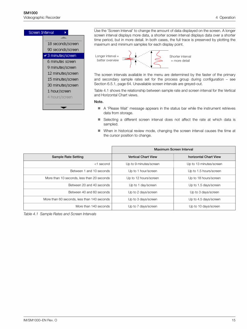
Use the 'Screen Interval' to change the amount of data displayed on the screen. A longerscreen interval displays more data, a shorter screen interval displays data over a shortertime period, but in more detail. In both cases, the full trace is preserved by plotting themaximum and minimum samples for each display point.
The screen intervals available in the menu are determined by the faster of the primaryand secondary sample rates set for the process group during configuration – seeSection 6.5.1, page 64. Unavailable screen intervals are greyed-out.
Table 4.1 shows the relationship between sample rate and screen interval for the Verticaland Horizontal Chart views.
Note.
A 'Please Wait' message appears in the status bar while the instrument retrievesdata from storage.
Selecting a different screen interval does not affect the rate at which data issampled.
When in historical review mode, changing the screen interval causes the time atthe cursor position to change.
Maximum Screen Interval
Sample Rate Setting Vertical Chart View horizontal Chart View
<1 second Up to 9 minutes/screen Up to 13 minutes/screen
Between 1 and 10 seconds Up to 1 hour/screen Up to 1.5 hours/screen
More than 10 seconds, less than 20 seconds Up to 12 hours/screen Up to 18 hours/screen
Between 20 and 40 seconds Up to 1 day/screen Up to 1.5 days/screen
Between 40 and 60 seconds Up to 2 days/screen Up to 3 days/screen
More than 60 seconds, less than 140 seconds Up to 3 days/screen Up to 4.5 days/screen
More than 140 seconds Up to 7 days/screen Up to 10 days/screen
Table 4.1 Sample Rates and Screen Intervals
������ ��� ��@ ���� �����
1���� ��� �� @*��� � �� ���
SM1000Videographic Recorder 4 Operation
16 IM/SM1000–EN Rev. O
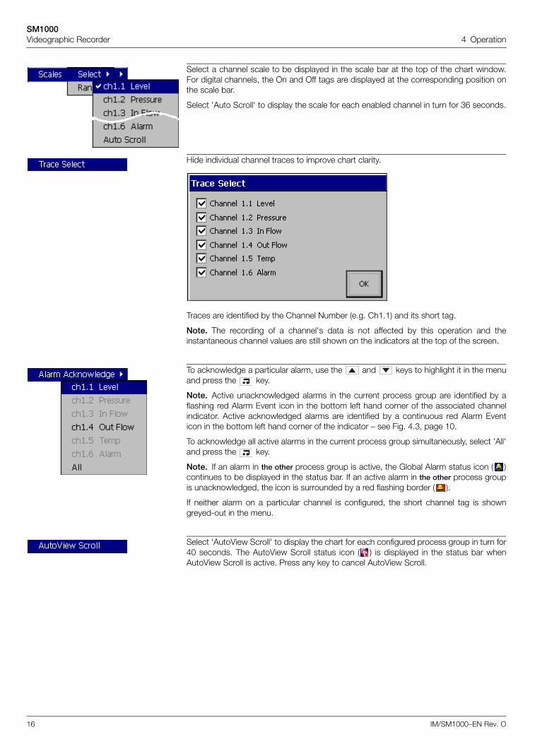
Select a channel scale to be displayed in the scale bar at the top of the chart window.For digital channels, the On and Off tags are displayed at the corresponding position onthe scale bar.
Select 'Auto Scroll' to display the scale for each enabled channel in turn for 36 seconds.
Hide individual channel traces to improve chart clarity.
Traces are identified by the Channel Number (e.g. Ch1.1) and its short tag.
Note. The recording of a channel's data is not affected by this operation and theinstantaneous channel values are still shown on the indicators at the top of the screen.
To acknowledge a particular alarm, use the and keys to highlight it in the menuand press the key.
Note. Active unacknowledged alarms in the current process group are identified by aflashing red Alarm Event icon in the bottom left hand corner of the associated channelindicator. Active acknowledged alarms are identified by a continuous red Alarm Eventicon in the bottom left hand corner of the indicator – see Fig. 4.3, page 10.
To acknowledge all active alarms in the current process group simultaneously, select 'All'and press the key.
Note. If an alarm in the other process group is active, the Global Alarm status icon ( )continues to be displayed in the status bar. If an active alarm in the other process groupis unacknowledged, the icon is surrounded by a red flashing border ( ).
If neither alarm on a particular channel is configured, the short channel tag is showngreyed-out in the menu.
Select 'AutoView Scroll' to display the chart for each configured process group in turn for40 seconds. The AutoView Scroll status icon ( ) is displayed in the status bar whenAutoView Scroll is active. Press any key to cancel AutoView Scroll.
SM1000Videographic Recorder 4 Operation
IM/SM1000–EN Rev. O 17
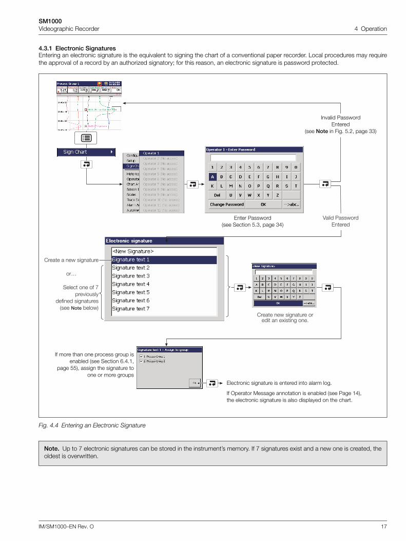
4.3.1 Electronic SignaturesEntering an electronic signature is the equivalent to signing the chart of a conventional paper recorder. Local procedures may requirethe approval of a record by an authorized signatory; for this reason, an electronic signature is password protected.
Fig. 4.4 Entering an Electronic Signature
Note. Up to 7 electronic signatures can be stored in the instrument’s memory. If 7 signatures exist and a new one is created, theoldest is overwritten.
4���� 5�������0����
����� � �� �������
��A
����� �� �� B��� ������
������ ������������ ��� *�����
����� �� ������� ����� � �.���� ��"
Invalid PasswordEntered
(see Note in Fig. 5.2, page 33)
Enter Password (see Section 5.3, page 34)
Electronic signature is entered into alarm log.
If Operator Message annotation is enabled (see Page 14), the electronic signature is also displayed on the chart.
If more than one process group isenabled (see Section 6.4.1,
page 55), assign the signature toone or more groups
SM1000Videographic Recorder 4 Operation
18 IM/SM1000–EN Rev. O
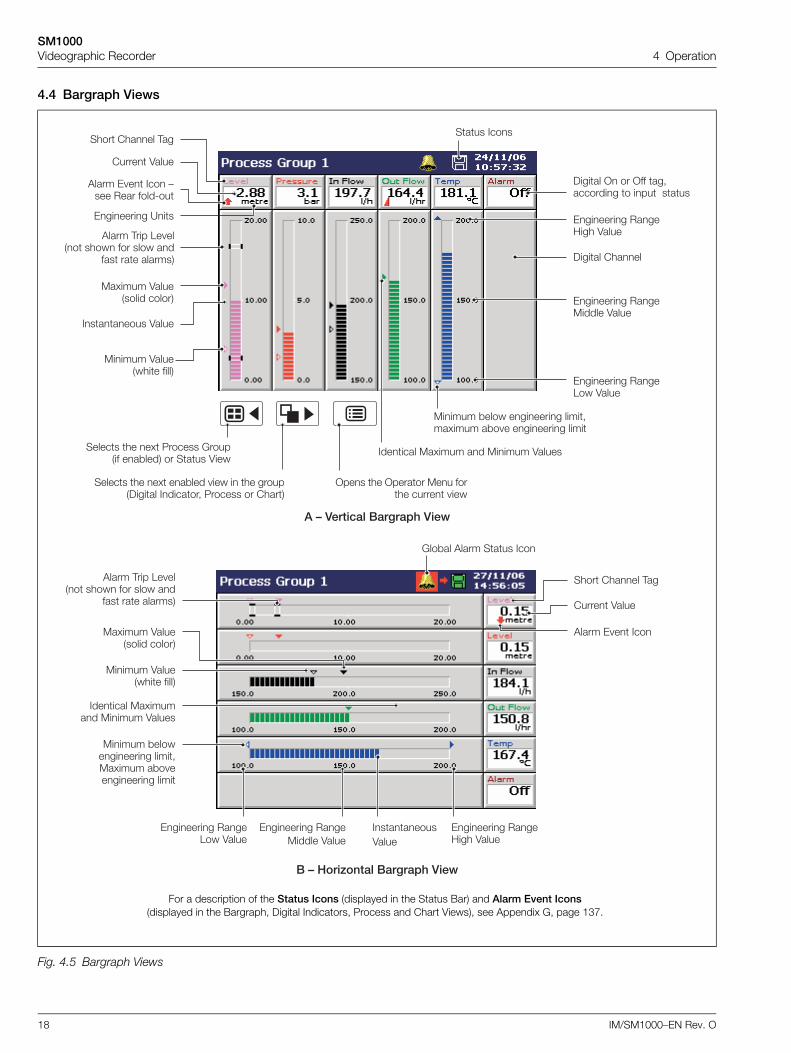
4.4 Bargraph Views
Fig. 4.5 Bargraph Views
�6)������(�� ���')�*
'���� ,��� 1� ���� ���� ��� ���� ��
��� ��� ������� )����� �����
��.���� 4���������� ������
������ 4��������� �����
�������� 4����
0������� ���������� 4����
)����� > �� >�� ��-�������� � ��� ����
0������� ����;��� 4����
0������� ����1�� 4����
���� ����� ,��
����� 4����
'���� 0 � ��� :��� ���� ����8��
0������� ?��
���� ����
������� ��.���� �� ������ 4�����
������ *���� �������� ����-��.���� �*� � �������� ����
������ �� �. 5������ 6������� ��*���� �� ���� 4���
������ �� �. ��*��� ��� � �� ������)����� �������- 5������ �� �����
>��� �� >������ ��� ����� ����� ���
(67���$�����(�� ���')�*
'���� ,��� 1� ���� ���� ��� ���� ��
��� ��� �������
6��*�� '���� ���� ���
��.���� 4���������� ������
���� ����� ,��
������ 4��������� �����
'���� 0 � ���
��������4����
0������� ���������� 4����
0������� ����;��� 4����
0������� ����1�� 4����
����� 4����
������� ��.������ ������ 4�����
������ *������������ ����-��.���� �*� ��������� ����
For a description of the Status Icons (displayed in the Status Bar) and Alarm Event Icons(displayed in the Bargraph, Digital Indicators, Process and Chart Views), see Appendix G, page 137.
SM1000Videographic Recorder 4 Operation
IM/SM1000–EN Rev. O 19
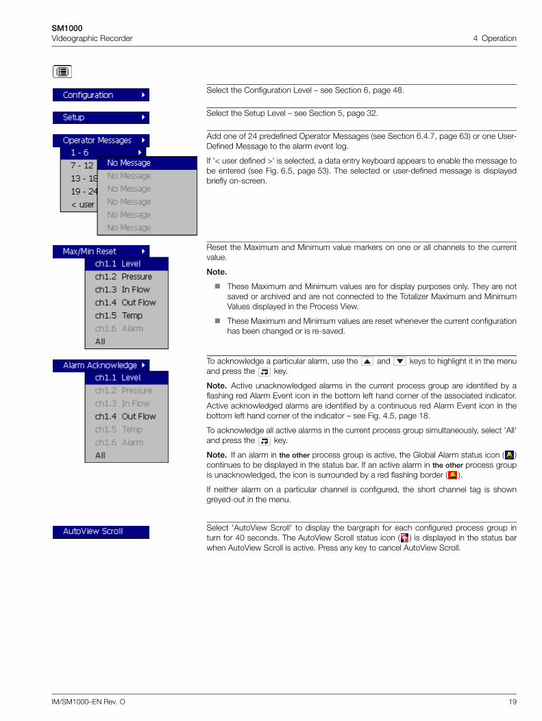
Select the Configuration Level – see Section 6, page 48.
Select the Setup Level – see Section 5, page 32.
Add one of 24 predefined Operator Messages (see Section 6.4.7, page 63) or one User-Defined Message to the alarm event log.
If '< user defined >' is selected, a data entry keyboard appears to enable the message tobe entered (see Fig. 6.5, page 53). The selected or user-defined message is displayedbriefly on-screen.
Reset the Maximum and Minimum value markers on one or all channels to the currentvalue.
Note.
These Maximum and Minimum values are for display purposes only. They are notsaved or archived and are not connected to the Totalizer Maximum and MinimumValues displayed in the Process View.
These Maximum and Minimum values are reset whenever the current configurationhas been changed or is re-saved.
To acknowledge a particular alarm, use the and keys to highlight it in the menuand press the key.
Note. Active unacknowledged alarms in the current process group are identified by aflashing red Alarm Event icon in the bottom left hand corner of the associated indicator.Active acknowledged alarms are identified by a continuous red Alarm Event icon in thebottom left hand corner of the indicator – see Fig. 4.5, page 18.
To acknowledge all active alarms in the current process group simultaneously, select 'All'and press the key.
Note. If an alarm in the other process group is active, the Global Alarm status icon ( )continues to be displayed in the status bar. If an active alarm in the other process groupis unacknowledged, the icon is surrounded by a red flashing border ( ).
If neither alarm on a particular channel is configured, the short channel tag is showngreyed-out in the menu.
Select 'AutoView Scroll' to display the bargraph for each configured process group inturn for 40 seconds. The AutoView Scroll status icon ( ) is displayed in the status barwhen AutoView Scroll is active. Press any key to cancel AutoView Scroll.
SM1000Videographic Recorder 4 Operation
20 IM/SM1000–EN Rev. O
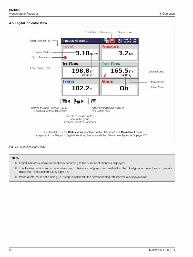
4.5 Digital Indicator View
Fig. 4.6 Digital Indicator View
Note.
Digital indicators resize automatically according to the number of channels displayed.
The totalizer option must be enabled and totalizers configured and enabled in the Configuration level before they aredisplayed – see Section 6.6.5, page 87.
When a totalizer is not running (i.e. 'Stop' is selected), the corresponding totalizer value is shown in red.
����� ?��
,����2�� 4����
,����2�� ?��
0������� ?��
6��*�� '���� ���� ���
������ �� �. 5������ 6������� ��*���� �� �� ���� 4���
������ �� �. ��*��� ��� � �� �����
�5������- ���� �� (��������
>��� �� >������ ��� ����� ����� ���
���� ����
���� ����� ,��
����� 4����
'���� 0 � ���
For a description of the Status Icons (displayed in the Status Bar) and Alarm Event Icons(displayed in the Bargraph, Digital Indicators, Process and Chart Views), see Appendix G, page 137.
SM1000Videographic Recorder 4 Operation
IM/SM1000–EN Rev. O 21
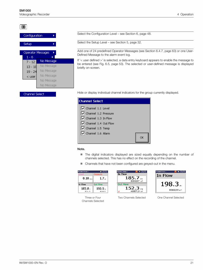
Select the Configuration Level – see Section 6, page 48.
Select the Setup Level – see Section 5, page 32.
Add one of 24 predefined Operator Messages (see Section 6.4.7, page 63) or one User-Defined Message to the alarm event log.
If '< user defined >' is selected, a data entry keyboard appears to enable the message tobe entered (see Fig. 6.5, page 53). The selected or user-defined message is displayedbriefly on-screen.
Hide or display individual channel indicators for the group currently displayed.
Note.
The digital indicators displayed are sized equally depending on the number ofchannels selected. This has no effect on the recording of the channel.
Channels that have not been configured are greyed-out in the menu.
,���� �� ���������� �������
,�� ������ ������� >� ����� �������
SM1000Videographic Recorder 4 Operation
22 IM/SM1000–EN Rev. O
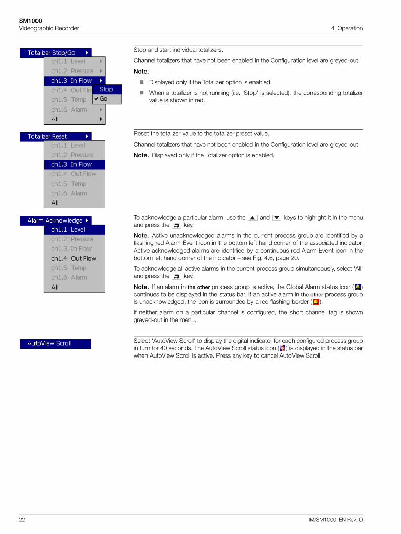
Stop and start individual totalizers.
Channel totalizers that have not been enabled in the Configuration level are greyed-out.
Note.
Displayed only if the Totalizer option is enabled.
When a totalizer is not running (i.e. 'Stop' is selected), the corresponding totalizervalue is shown in red.
Reset the totalizer value to the totalizer preset value.
Channel totalizers that have not been enabled in the Configuration level are greyed-out.
Note. Displayed only if the Totalizer option is enabled.
To acknowledge a particular alarm, use the and keys to highlight it in the menuand press the key.
Note. Active unacknowledged alarms in the current process group are identified by aflashing red Alarm Event icon in the bottom left hand corner of the associated indicator.Active acknowledged alarms are identified by a continuous red Alarm Event icon in thebottom left hand corner of the indicator – see Fig. 4.6, page 20.
To acknowledge all active alarms in the current process group simultaneously, select 'All'and press the key.
Note. If an alarm in the other process group is active, the Global Alarm status icon ( )continues to be displayed in the status bar. If an active alarm in the other process groupis unacknowledged, the icon is surrounded by a red flashing border ( ).
If neither alarm on a particular channel is configured, the short channel tag is showngreyed-out in the menu.
Select 'AutoView Scroll' to display the digital indicator for each configured process groupin turn for 40 seconds. The AutoView Scroll status icon ( ) is displayed in the status barwhen AutoView Scroll is active. Press any key to cancel AutoView Scroll.
SM1000Videographic Recorder 4 Operation
IM/SM1000–EN Rev. O 23
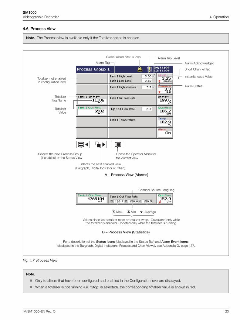
4.6 Process View
Note. The Process view is available only if the Totalizer option is enabled.
Fig. 4.7 Process View
Note.
Only totalizers that have been configured and enabled in the Configuration level are displayed.
When a totalizer is not running (i.e. 'Stop' is selected), the corresponding totalizer value is shown in red.
��
(6������)�* ����������"
,����2��,�� 9���
,����2��4����
,����2�� � ��*��� � ���������� �� ��
'���� ,��'���� ,��� 1� ��
'���� '�<��������
�6������)�* ������"
4����� ���� ��� ����2�� ���� �� ����2�� ����" ��������� ��� ������� ����2�� �� ��*���" ?����� ��� ����� �� ����2�� �� ����"
����� ������ 1�� ,��
' �������.
���� ����� ,��
'���� ����
�������� 4����
6��*�� '���� ���� ���
������ �� �. 5������ 6������� ��*���� �� �� ���� 4���
������ �� �. ��*��� ����(�������- )����� ������� �� �����
>��� �� >������ ��� ����� ����� ���
For a description of the Status Icons (displayed in the Status Bar) and Alarm Event Icons(displayed in the Bargraph, Digital Indicators, Process and Chart Views), see Appendix G, page 137.
SM1000Videographic Recorder 4 Operation
24 IM/SM1000–EN Rev. O
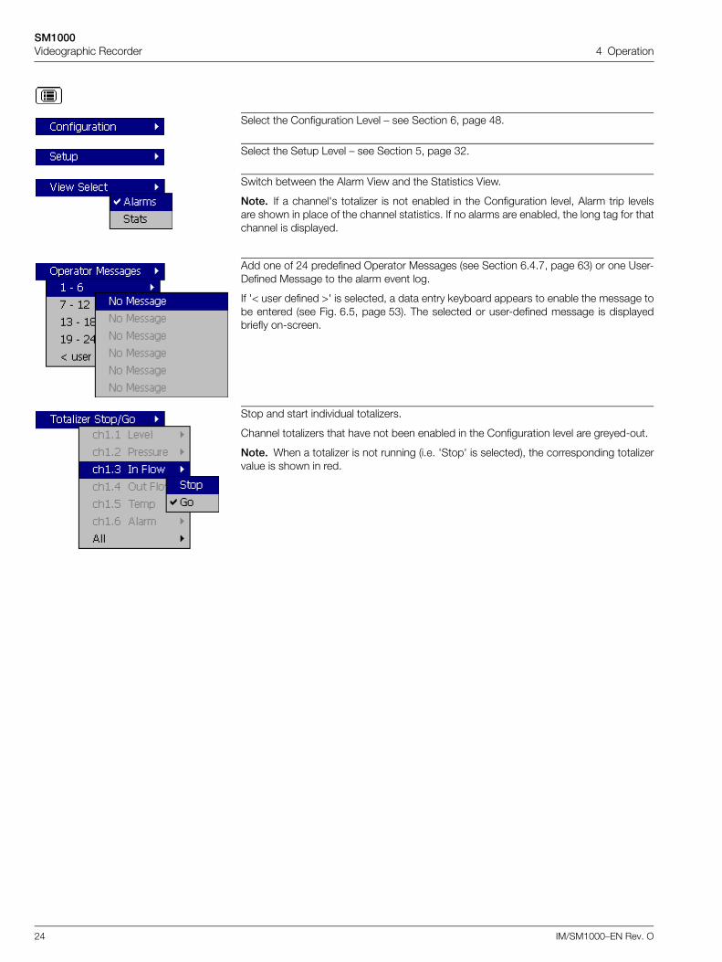
Select the Configuration Level – see Section 6, page 48.
Select the Setup Level – see Section 5, page 32.
Switch between the Alarm View and the Statistics View.
Note. If a channel's totalizer is not enabled in the Configuration level, Alarm trip levelsare shown in place of the channel statistics. If no alarms are enabled, the long tag for thatchannel is displayed.
Add one of 24 predefined Operator Messages (see Section 6.4.7, page 63) or one User-Defined Message to the alarm event log.
If '< user defined >' is selected, a data entry keyboard appears to enable the message tobe entered (see Fig. 6.5, page 53). The selected or user-defined message is displayedbriefly on-screen.
Stop and start individual totalizers.
Channel totalizers that have not been enabled in the Configuration level are greyed-out.
Note. When a totalizer is not running (i.e. 'Stop' is selected), the corresponding totalizervalue is shown in red.
SM1000Videographic Recorder 4 Operation
IM/SM1000–EN Rev. O 25
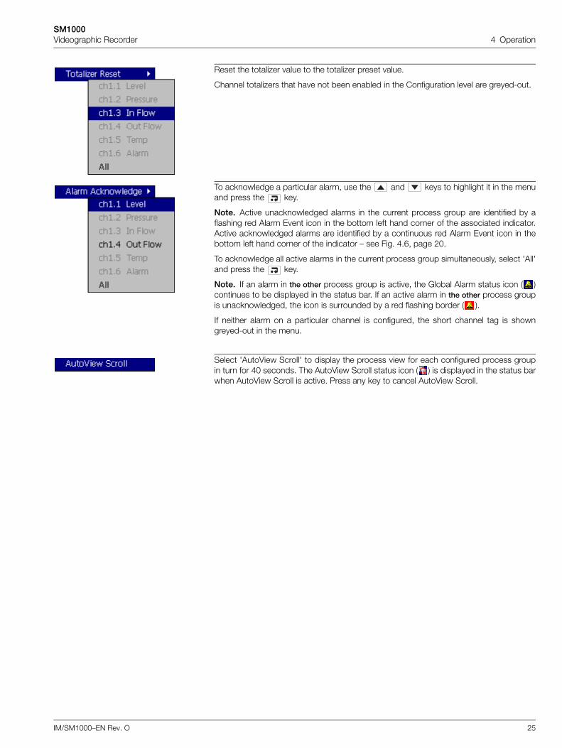
Reset the totalizer value to the totalizer preset value.
Channel totalizers that have not been enabled in the Configuration level are greyed-out.
To acknowledge a particular alarm, use the and keys to highlight it in the menuand press the key.
Note. Active unacknowledged alarms in the current process group are identified by aflashing red Alarm Event icon in the bottom left hand corner of the associated indicator.Active acknowledged alarms are identified by a continuous red Alarm Event icon in thebottom left hand corner of the indicator – see Fig. 4.6, page 20.
To acknowledge all active alarms in the current process group simultaneously, select 'All'and press the key.
Note. If an alarm in the other process group is active, the Global Alarm status icon ( )continues to be displayed in the status bar. If an active alarm in the other process groupis unacknowledged, the icon is surrounded by a red flashing border ( ).
If neither alarm on a particular channel is configured, the short channel tag is showngreyed-out in the menu.
Select 'AutoView Scroll' to display the process view for each configured process groupin turn for 40 seconds. The AutoView Scroll status icon ( ) is displayed in the status barwhen AutoView Scroll is active. Press any key to cancel AutoView Scroll.
SM1000Videographic Recorder 4 Operation
26 IM/SM1000–EN Rev. O
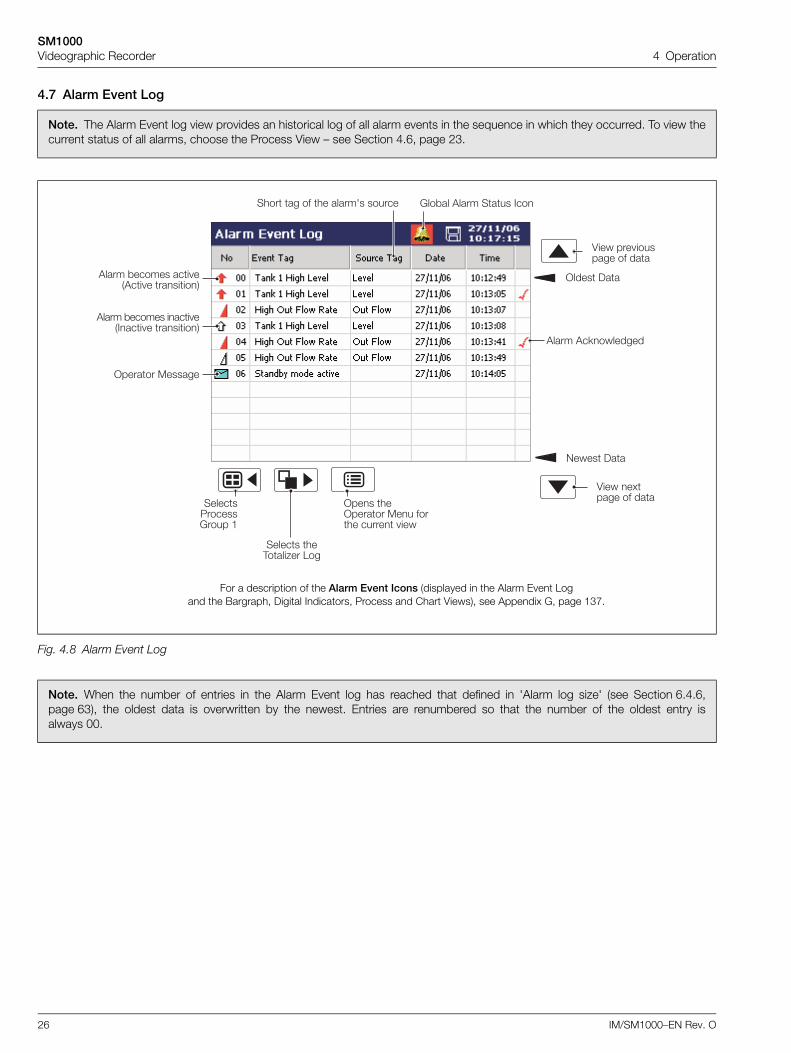
4.7 Alarm Event Log
Note. The Alarm Event log view provides an historical log of all alarm events in the sequence in which they occurred. To view thecurrent status of all alarms, choose the Process View – see Section 4.6, page 23.
Fig. 4.8 Alarm Event Log
Note. When the number of entries in the Alarm Event log has reached that defined in 'Alarm log size' (see Section 6.4.6,page 63), the oldest data is overwritten by the newest. Entries are renumbered so that the number of the oldest entry isalways 00.
9���� )��
4��� ��� �������� �� ���
>���� )��
4��� �.���� �� ���������
5������6���� �
������ ��,����2�� 1��
>��� ��>������ ��� ����� ����� ���
'���� *������ ��� � �'�� � �������
'���� '�<��������
'���� *������ ���� � ����� � �������
>������ �������
���� �� �� �� �����7� ������ 6��*�� '���� ���� ���
For a description of the Alarm Event Icons (displayed in the Alarm Event Logand the Bargraph, Digital Indicators, Process and Chart Views), see Appendix G, page 137.
SM1000Videographic Recorder 4 Operation
IM/SM1000–EN Rev. O 27
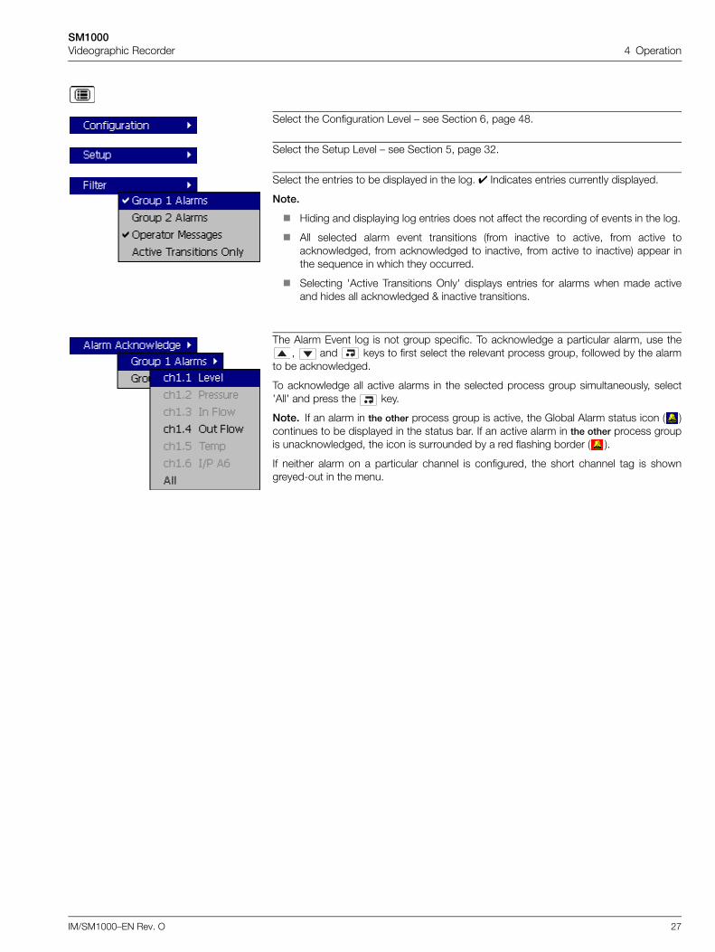
Select the Configuration Level – see Section 6, page 48.
Select the Setup Level – see Section 5, page 32.
Select the entries to be displayed in the log. Indicates entries currently displayed.
Note.
Hiding and displaying log entries does not affect the recording of events in the log.
All selected alarm event transitions (from inactive to active, from active toacknowledged, from acknowledged to inactive, from active to inactive) appear inthe sequence in which they occurred.
Selecting 'Active Transitions Only' displays entries for alarms when made activeand hides all acknowledged & inactive transitions.
The Alarm Event log is not group specific. To acknowledge a particular alarm, use the, and keys to first select the relevant process group, followed by the alarm
to be acknowledged.
To acknowledge all active alarms in the selected process group simultaneously, select'All' and press the key.
Note. If an alarm in the other process group is active, the Global Alarm status icon ( )continues to be displayed in the status bar. If an active alarm in the other process groupis unacknowledged, the icon is surrounded by a red flashing border ( ).
If neither alarm on a particular channel is configured, the short channel tag is showngreyed-out in the menu.
SM1000Videographic Recorder 4 Operation
28 IM/SM1000–EN Rev. O
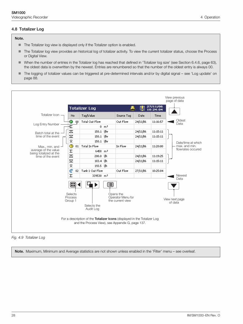
4.8 Totalizer Log
Note.
The Totalizer log view is displayed only if the Totalizer option is enabled.
The Totalizer log view provides an historical log of totalizer activity. To view the current totalizer status, choose the Processor Digital View.
When the number of entries in the Totalizer log has reached that defined in 'Totalizer log size' (see Section 6.4.6, page 63),the oldest data is overwritten by the newest. Entries are renumbered so that the number of the oldest entry is always 00.
The logging of totalizer values can be triggered at pre-determined intervals and/or by digital signal – see 'Log update' onpage 88.
Fig. 4.9 Totalizer Log
Note. Maximum, Minimum and Average statistics are not shown unless enabled in the 'Filter' menu – see overleaf.
4��� �. ������ ���
9����)��
4��� ��� �������� �� ���
>����)��
������5������6���� �
������ ��'��� 1��
>��� ��>������ ��� ����� ����� ���
1�� 0�� 9��*��
,����2�� ���
(��� ��� � ����� �� �� � �
��."- ��" ��� ����� �� �� ����*��� ����2�� � ��
��� �� �� � �
)��/��� � �������." �� ��"�������� �������
For a description of the Totalizer Icons (displayed in the Totalizer Log and the Process View), see Appendix G, page 137.
SM1000Videographic Recorder 4 Operation
IM/SM1000–EN Rev. O 29
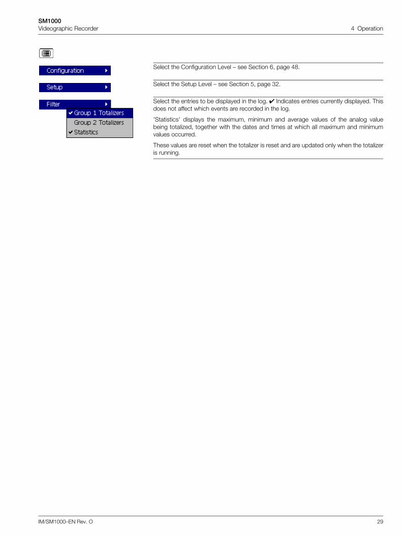
Select the Configuration Level – see Section 6, page 48.
Select the Setup Level – see Section 5, page 32.
Select the entries to be displayed in the log. Indicates entries currently displayed. Thisdoes not affect which events are recorded in the log.
'Statistics' displays the maximum, minimum and average values of the analog valuebeing totalized, together with the dates and times at which all maximum and minimumvalues occurred.
These values are reset when the totalizer is reset and are updated only when the totalizeris running.
SM1000Videographic Recorder 4 Operation
30 IM/SM1000–EN Rev. O
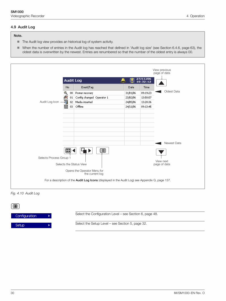
4.9 Audit Log
Note.
The Audit log view provides an historical log of system activity.
When the number of entries in the Audit log has reached that defined in 'Audit log size' (see Section 6.4.6, page 63), theoldest data is overwritten by the newest. Entries are renumbered so that the number of the oldest entry is always 00.
Fig. 4.10 Audit Log
Select the Configuration Level – see Section 6, page 48.
Select the Setup Level – see Section 5, page 32.
9���� )��
4��� ��� �������� �� ���
>���� )��
4��� �.���� �� ���
'��� 1�� ���
������ 5������ 6���� �
������ �� ���� 4���
>��� �� >������ ��� ����� ����� ���
For a description of the Audit Log Icons (displayed in the Audit Log) see Appendix G, page 137.
SM1000Videographic Recorder 4 Operation
IM/SM1000–EN Rev. O 31
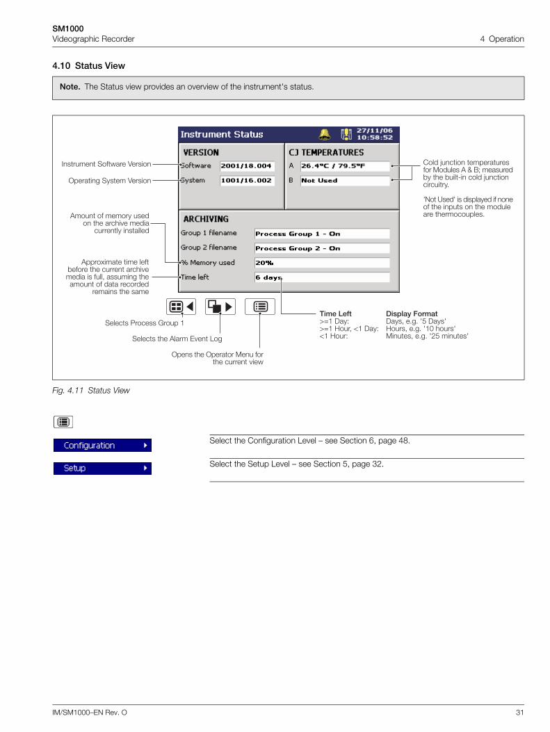
4.10 Status View
Note. The Status view provides an overview of the instrument's status.
Fig. 4.11 Status View
Select the Configuration Level – see Section 6, page 48.
Select the Setup Level – see Section 5, page 32.
#���0� ������38�����C@� )��D )���- �"�" 7% )���7C@� ;���- E� )��D ;����- �"�" 7�F �����7E� ;���D �����- �"�" 7!% �����7
������ 5������ 6���� �
������ �� '���� 0 � 1��
>��� �� >������ ��� ����� ����� ���
������ ������� 4�����
>������ ����� 4�����
���� G���� ������������� ������� ' H (I ��������*� �� *���8� ���� G������������"
79� ?���7 �� ��������� �� ���� �� ���� � �� ��������� ������������"'��� �� ������ ����
� �� ����� � ������������ �������
'����.���� ��� ���*����� �� ����� ����� ������ �� ����- ������� ������ �� ��� ��������
������ �� ����
SM1000Videographic Recorder 5 Setup
32 IM/SM1000–EN Rev. O
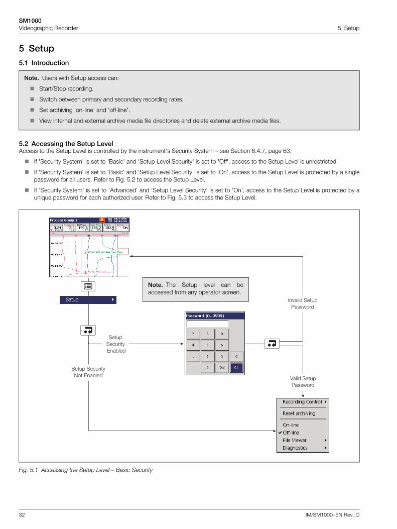
5 Setup5.1 Introduction
5.2 Accessing the Setup LevelAccess to the Setup Level is controlled by the instrument's Security System – see Section 6.4.7, page 63.
If 'Security System' is set to 'Basic' and 'Setup Level Security' is set to 'Off', access to the Setup Level is unrestricted.
If 'Security System' is set to 'Basic' and 'Setup Level Security' is set to 'On', access to the Setup Level is protected by a singlepassword for all users. Refer to Fig. 5.2 to access the Setup Level.
If 'Security System' is set to 'Advanced' and 'Setup Level Security' is set to 'On', access to the Setup Level is protected by aunique password for each authorized user. Refer to Fig. 5.3 to access the Setup Level.
Note. Users with Setup access can:
Start/Stop recording.
Switch between primary and secondary recording rates.
Set archiving 'on-line' and 'off-line'.
View internal and external archive media file directories and delete external archive media files.
Fig. 5.1 Accessing the Setup Level – Basic Security
���� �������9� 0�*���
����������� 0�*���
4���� ����5�������
� ���� ����5�������
Note. The Setup level can beaccessed from any operator screen.
SM1000Videographic Recorder 5 Setup
IM/SM1000–EN Rev. O 33
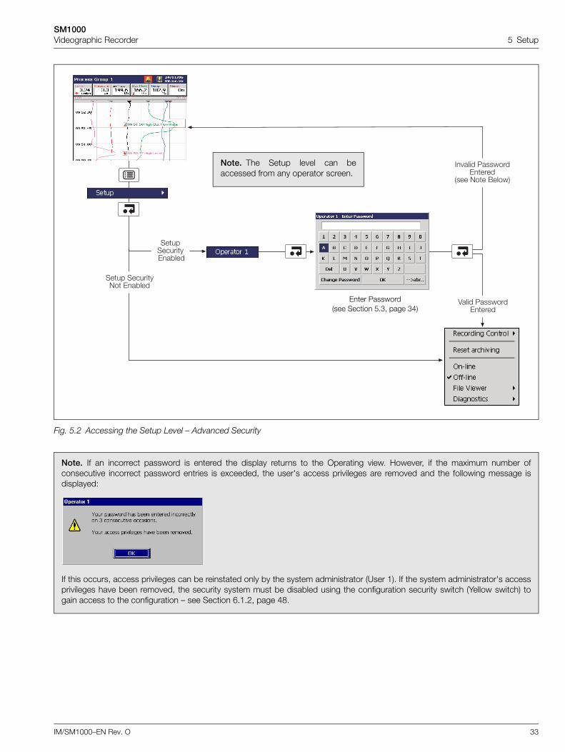
Fig. 5.2 Accessing the Setup Level – Advanced Security
Note. If an incorrect password is entered the display returns to the Operating view. However, if the maximum number ofconsecutive incorrect password entries is exceeded, the user's access privileges are removed and the following message isdisplayed:
If this occurs, access privileges can be reinstated only by the system administrator (User 1). If the system administrator's accessprivileges have been removed, the security system must be disabled using the configuration security switch (Yellow switch) togain access to the configuration – see Section 6.1.2, page 48.
� ���� 5�������0����
���� 9�� (�����
4���� 5�������0����
���� �������9� 0�*���
����������� 0�*���
Enter Password (see Section 5.3, page 34)
Note. The Setup level can beaccessed from any operator screen.
SM1000Videographic Recorder 5 Setup
34 IM/SM1000–EN Rev. O
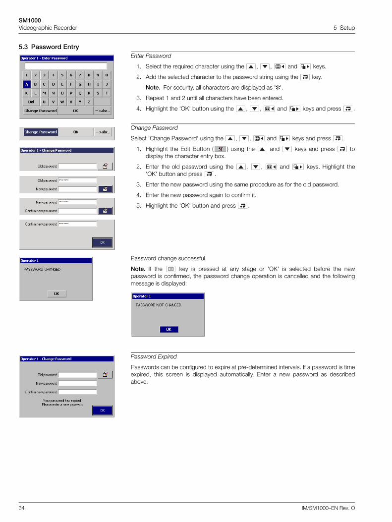
5.3 Password EntryEnter Password
1. Select the required character using the , , and keys.
2. Add the selected character to the password string using the key.
Note. For security, all characters are displayed as ''.
3. Repeat 1 and 2 until all characters have been entered.
4. Highlight the 'OK' button using the , , and keys and press .
Change Password
Select 'Change Password' using the , , and keys and press .
1. Highlight the Edit Button ( ) using the and keys and press todisplay the character entry box.
2. Enter the old password using the , , and keys. Highlight the'OK' button and press .
3. Enter the new password using the same procedure as for the old password.
4. Enter the new password again to confirm it.
5. Highlight the 'OK' button and press .
Password change successful.
Note. If the key is pressed at any stage or 'OK' is selected before the newpassword is confirmed, the password change operation is cancelled and the followingmessage is displayed:
Password Expired
Passwords can be configured to expire at pre-determined intervals. If a password is timeexpired, this screen is displayed automatically. Enter a new password as describedabove.
SM1000Videographic Recorder 5 Setup
IM/SM1000–EN Rev. O 35
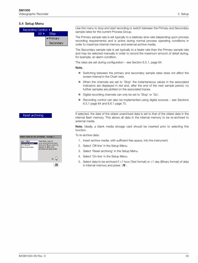
5.4 Setup MenuUse this menu to stop and start recording or switch between the Primary and Secondarysample rates for the current Process Group.
The Primary sample rate is set typically to a relatively slow rate (depending upon processrecording requirements) and is active during normal process operating conditions inorder to maximize internal memory and external archive media.
The Secondary sample rate is set typically to a faster rate than the Primary sample rateand may be selected manually in order to record the maximum amount of detail during,for example, an alarm condition.
The rates are set during configuration – see Section 6.5.1, page 64.
Note.
Switching between the primary and secondary sample rates does not affect thescreen interval in the Chart view.
When the channels are set to 'Stop' the instantaneous values in the associatedindicators are displayed in red and, after the end of the next sample period, nofurther samples are plotted on the associated traces.
Digital recording channels can only be set to 'Stop' or 'Go'.
Recording control can also be implemented using digital sources – see Sections6.5.1 page 64 and 6.6.1 page 75.
If selected, the date of the oldest unarchived data is set to that of the oldest data in theinternal flash memory. This allows all data in the internal memory to be re-archived toexternal media.
Note. Ideally, a blank media storage card should be inserted prior to selecting thisfunction.
To re-archive data:
1. Insert archive media, with sufficient free space, into the instrument.
2. Select 'Off-line' in the Setup Menu.
3. Select 'Reset archiving' in the Setup Menu.
4. Select 'On-line' in the Setup Menu.
5. Select data to be archived if >1 hour (Text format) or >1 day (Binary format) of datain internal memory and press .
SM1000Videographic Recorder 5 Setup
36 IM/SM1000–EN Rev. O
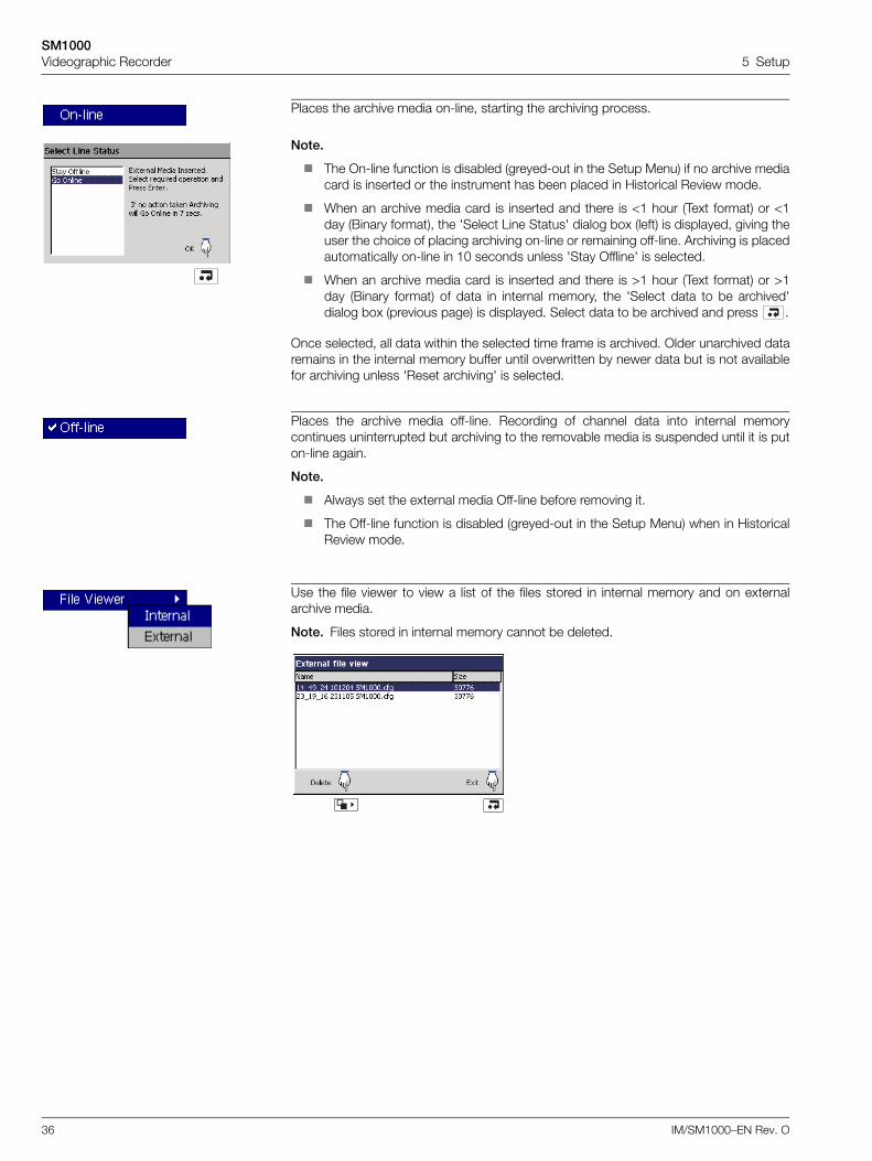
Places the archive media on-line, starting the archiving process.
Note.
The On-line function is disabled (greyed-out in the Setup Menu) if no archive mediacard is inserted or the instrument has been placed in Historical Review mode.
When an archive media card is inserted and there is <1 hour (Text format) or <1day (Binary format), the 'Select Line Status' dialog box (left) is displayed, giving theuser the choice of placing archiving on-line or remaining off-line. Archiving is placedautomatically on-line in 10 seconds unless 'Stay Offline' is selected.
When an archive media card is inserted and there is >1 hour (Text format) or >1day (Binary format) of data in internal memory, the 'Select data to be archived'dialog box (previous page) is displayed. Select data to be archived and press .
Once selected, all data within the selected time frame is archived. Older unarchived dataremains in the internal memory buffer until overwritten by newer data but is not availablefor archiving unless 'Reset archiving' is selected.
Places the archive media off-line. Recording of channel data into internal memorycontinues uninterrupted but archiving to the removable media is suspended until it is puton-line again.
Note.
Always set the external media Off-line before removing it.
The Off-line function is disabled (greyed-out in the Setup Menu) when in HistoricalReview mode.
Use the file viewer to view a list of the files stored in internal memory and on externalarchive media.
Note. Files stored in internal memory cannot be deleted.
SM1000Videographic Recorder 5 Setup
IM/SM1000–EN Rev. O 37
5.5 ArchivingRecorded data, logs and configuration files stored on the instrument's internal memory can be archived to files created on removablemedia. Parameters for archiving Process Groups 1 and 2 data are set up independently.
5.5.1 Card CompatibilityOur recorders comply with approved industry standards for memory cards. SanDisk Standard Grade memory cards have been fullytested and are recommended for use with our recorders. Other brands may not be fully compatible with this device and therefore maynot function correctly.
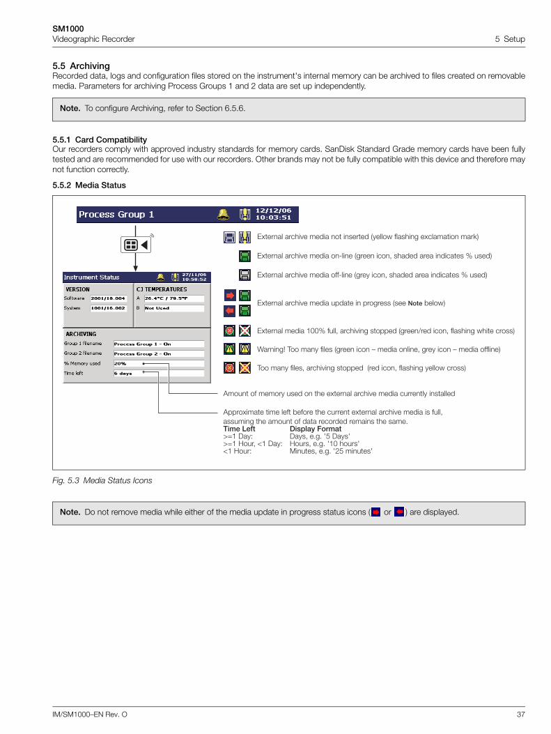
5.5.2 Media Status
Note. To configure Archiving, refer to Section 6.5.6.
Fig. 5.3 Media Status Icons
Note. Do not remove media while either of the media update in progress status icons ( or ) are displayed.
'��� �� ������ ���� � �� �.���� ����� � ����� ������� �������
'����.���� ��� ��� *����� �� ����� �.���� ����� � ����� �� ����-������� �� ���� �� ��� �������� ������ �� ����"#���0� ������38�����C@� )��D )���- �"�" 7% )���7C@� ;���- E� )��D ;����- �"�" 7�F �����7E� ;���D �����- �"�" 7!% �����7
0.���� ����� � ����� � ������ ������� ������� �.������� ���<�
0.���� ����� � ����� �8��� ����� ���- ������ ���� ������� J �����
0.���� ����� � ����� ���8��� ����� ���- ������ ���� ������� J �����
0.���� ����� � ����� ����� � �������� ���� ��� *�����
0.���� ����� �FFJ ����- ����� �� ������ �����/��� ���- ������� ���� ������
K����L ,�� ��� ����� ����� ��� : ����� ����- ���� ��� : ����� �������
,�� ��� �����- ����� �� ������ ���� ���- ������� ������ ������
SM1000Videographic Recorder 5 Setup
38 IM/SM1000–EN Rev. O
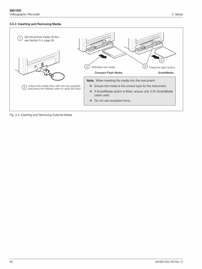
5.5.3 Inserting and Removing Media
Fig. 5.4 Inserting and Removing External Media
5���� �� �G�� *��
?���< �� ����� ���� ��� �� <�� ���������� ����� �� ������� ���� � ��� �� ����
K������ �� �����
�
!
#$
$
,������8���'1��� �����1���
Set the archive media off-line – see Section 5.4, page 36
Note. When inserting the media into the instrument:
Ensure the media is the correct type for the instrument.
If SmartMedia option is fitted, ensure only 3.3V SmartMediacards used.
Do not use excessive force.
SM1000Videographic Recorder 5 Setup
IM/SM1000–EN Rev. O 39
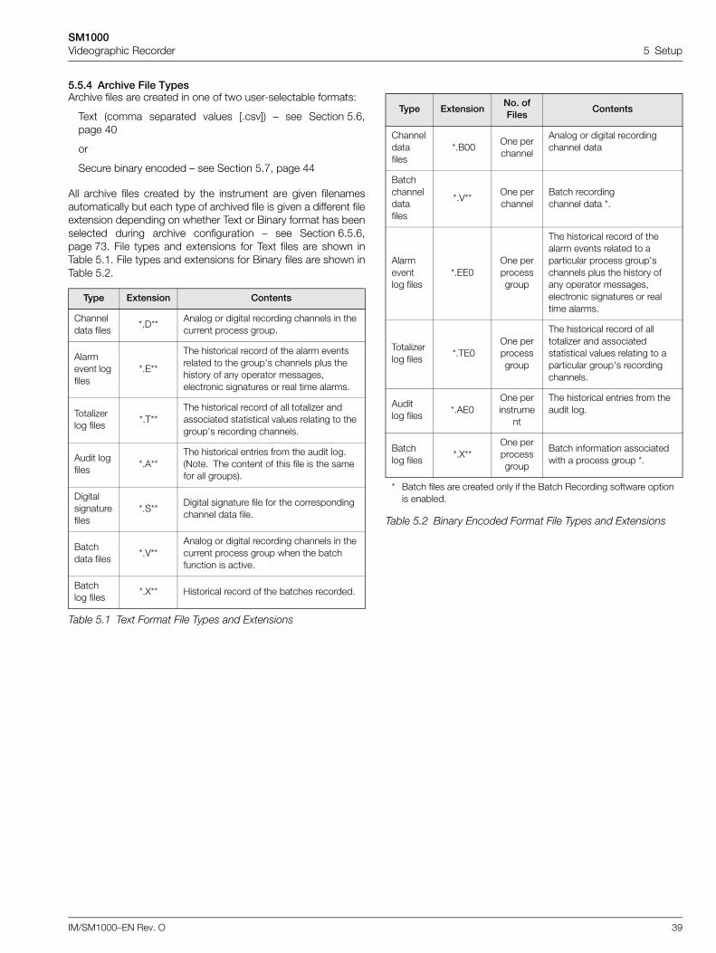
5.5.4 Archive File TypesArchive files are created in one of two user-selectable formats:
Text (comma separated values [.csv]) – see Section 5.6,page 40
or
Secure binary encoded – see Section 5.7, page 44
All archive files created by the instrument are given filenamesautomatically but each type of archived file is given a different fileextension depending on whether Text or Binary format has beenselected during archive configuration – see Section 6.5.6,page 73. File types and extensions for Text files are shown inTable 5.1. File types and extensions for Binary files are shown inTable 5.2.
Type Extension Contents
Channel data files
*.D**Analog or digital recording channels in the current process group.
Alarm event log files
*.E**
The historical record of the alarm events related to the group's channels plus the history of any operator messages, electronic signatures or real time alarms.
Totalizer log files
*.T**The historical record of all totalizer and associated statistical values relating to the group's recording channels.
Audit log files
*.A**The historical entries from the audit log.(Note. The content of this file is the same for all groups).
Digital signature files
*.S**Digital signature file for the corresponding channel data file.
Batch data files
*.V**Analog or digital recording channels in the current process group when the batch function is active.
Batch log files
*.X** Historical record of the batches recorded.
Table 5.1 Text Format File Types and Extensions
Type ExtensionNo. of Files
Contents
Channel data files
*.B00One per channel
Analog or digital recording channel data
Batch channel data files
*.V**One per channel
Batch recording channel data *.
Alarm event log files
*.EE0One per process group
The historical record of the alarm events related to a particular process group's channels plus the history of any operator messages, electronic signatures or real time alarms.
Totalizer log files
*.TE0One per process group
The historical record of all totalizer and associated statistical values relating to a particular group's recording channels.
Audit log files
*.AE0One per instrume
nt
The historical entries from the audit log.
Batch log files
*.X**One per process group
Batch information associated with a process group *.
* Batch files are created only if the Batch Recording software option is enabled.
Table 5.2 Binary Encoded Format File Types and Extensions
SM1000Videographic Recorder 5 Setup
40 IM/SM1000–EN Rev. O
5.6 Text Format Archive Files
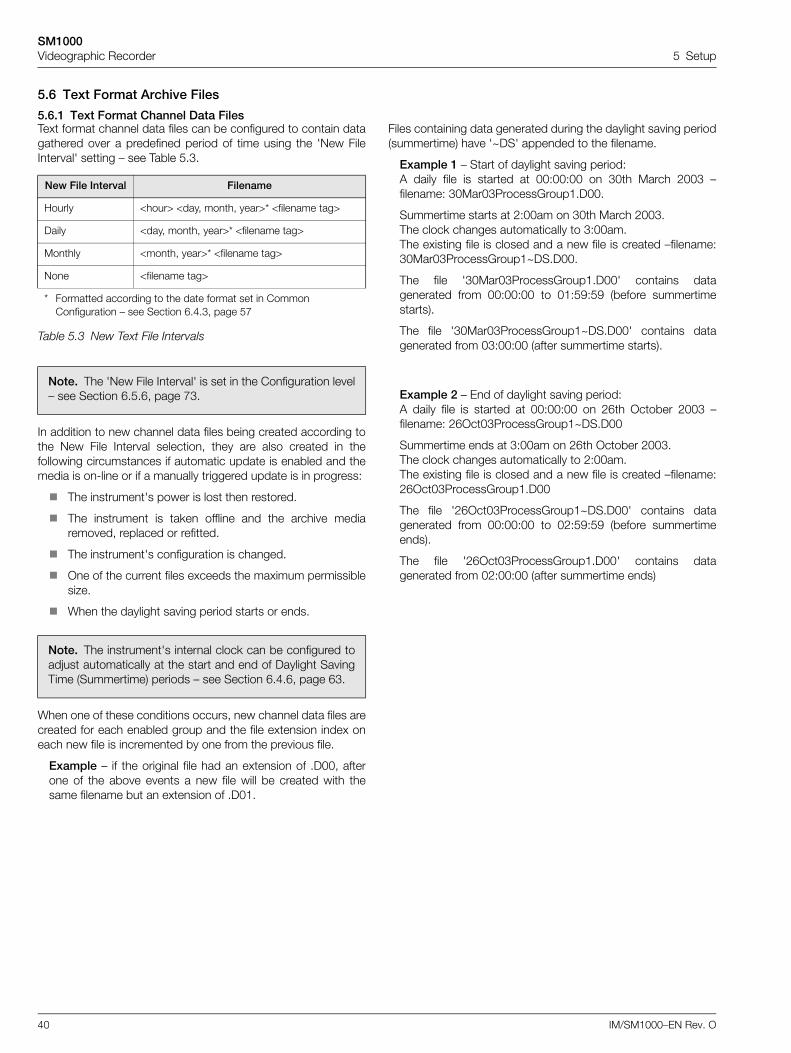
5.6.1 Text Format Channel Data FilesText format channel data files can be configured to contain datagathered over a predefined period of time using the 'New FileInterval' setting – see Table 5.3.
In addition to new channel data files being created according tothe New File Interval selection, they are also created in thefollowing circumstances if automatic update is enabled and themedia is on-line or if a manually triggered update is in progress:
The instrument's power is lost then restored.
The instrument is taken offline and the archive mediaremoved, replaced or refitted.
The instrument's configuration is changed.
One of the current files exceeds the maximum permissiblesize.
When the daylight saving period starts or ends.
When one of these conditions occurs, new channel data files arecreated for each enabled group and the file extension index oneach new file is incremented by one from the previous file.
Example – if the original file had an extension of .D00, afterone of the above events a new file will be created with thesame filename but an extension of .D01.
Files containing data generated during the daylight saving period(summertime) have '~DS' appended to the filename.
Example 1 – Start of daylight saving period:A daily file is started at 00:00:00 on 30th March 2003 –filename: 30Mar03ProcessGroup1.D00.
Summertime starts at 2:00am on 30th March 2003.The clock changes automatically to 3:00am.The existing file is closed and a new file is created –filename:30Mar03ProcessGroup1~DS.D00.
The file '30Mar03ProcessGroup1.D00' contains datagenerated from 00:00:00 to 01:59:59 (before summertimestarts).
The file '30Mar03ProcessGroup1~DS.D00' contains datagenerated from 03:00:00 (after summertime starts).
Example 2 – End of daylight saving period:A daily file is started at 00:00:00 on 26th October 2003 –filename: 26Oct03ProcessGroup1~DS.D00
Summertime ends at 3:00am on 26th October 2003.The clock changes automatically to 2:00am.The existing file is closed and a new file is created –filename:26Oct03ProcessGroup1.D00
The file '26Oct03ProcessGroup1~DS.D00' contains datagenerated from 00:00:00 to 02:59:59 (before summertimeends).
The file '26Oct03ProcessGroup1.D00' contains datagenerated from 02:00:00 (after summertime ends)
New File Interval Filename
Hourly <hour> <day, month, year>* <filename tag>
Daily <day, month, year>* <filename tag>
Monthly <month, year>* <filename tag>
None <filename tag>
* Formatted according to the date format set in Common Configuration – see Section 6.4.3, page 57
Table 5.3 New Text File Intervals
Note. The 'New File Interval' is set in the Configuration level– see Section 6.5.6, page 73.
Note. The instrument's internal clock can be configured toadjust automatically at the start and end of Daylight SavingTime (Summertime) periods – see Section 6.4.6, page 63.
SM1000Videographic Recorder 5 Setup
IM/SM1000–EN Rev. O 41
5.6.2 Text Format Filename Examples'New file interval' set to 'Hourly', 'Filename tag' set to 'ProcessGroup 1' (see Section 6.5.6, page 73); date is 10th October2000; Channel data and alarm event log files only enabled:
9:00 amNew file created in which all channel data recordedbetween 9:00 and 9:59:59 is archived in the following file:09_00_10Oct00_Process_Group_1.d00
09:12amPower interrupt occurs
09:13amPower restored and new file created:09_00_10Oct00_Process_Group_1.d01
10:00amNew file created in which all data recorded between10:00 and 10:59:59 is archived.10_00_10Oct00_Process_Group_1.d00
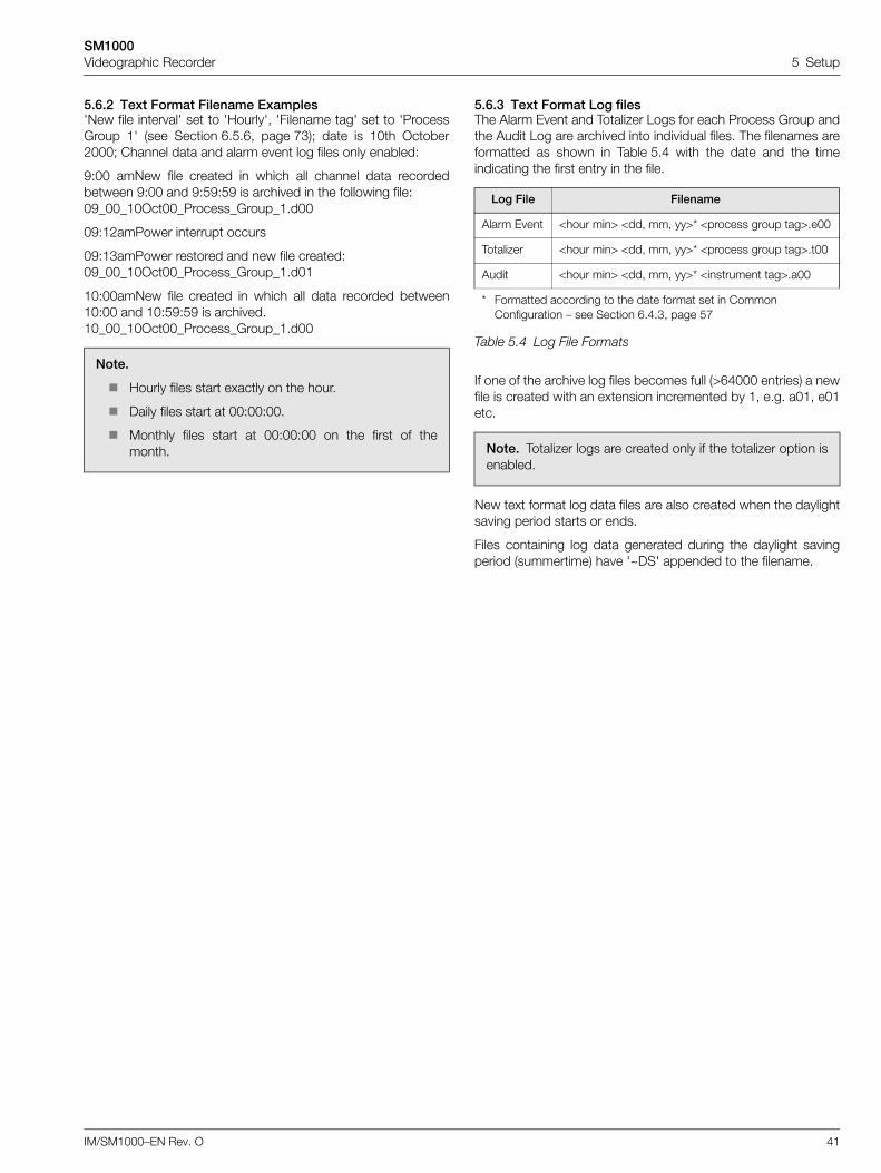
5.6.3 Text Format Log filesThe Alarm Event and Totalizer Logs for each Process Group andthe Audit Log are archived into individual files. The filenames areformatted as shown in Table 5.4 with the date and the timeindicating the first entry in the file.
If one of the archive log files becomes full (>64000 entries) a newfile is created with an extension incremented by 1, e.g. a01, e01etc.
New text format log data files are also created when the daylightsaving period starts or ends.
Files containing log data generated during the daylight savingperiod (summertime) have '~DS' appended to the filename.
Note.
Hourly files start exactly on the hour.
Daily files start at 00:00:00.
Monthly files start at 00:00:00 on the first of themonth.
Log File Filename
Alarm Event <hour min> <dd, mm, yy>* <process group tag>.e00
Totalizer <hour min> <dd, mm, yy>* <process group tag>.t00
Audit <hour min> <dd, mm, yy>* <instrument tag>.a00
* Formatted according to the date format set in Common Configuration – see Section 6.4.3, page 57
Table 5.4 Log File Formats
Note. Totalizer logs are created only if the totalizer option isenabled.
SM1000Videographic Recorder 5 Setup
42 IM/SM1000–EN Rev. O
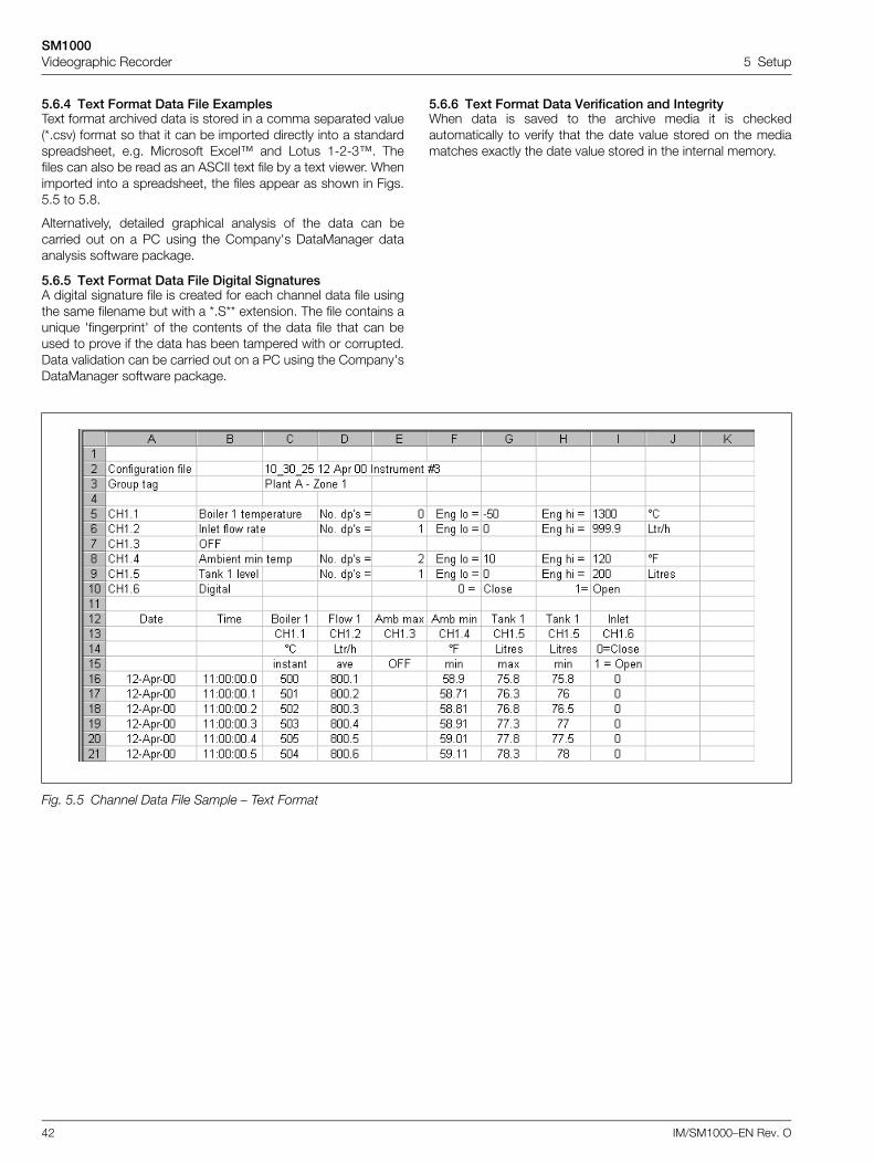
5.6.4 Text Format Data File ExamplesText format archived data is stored in a comma separated value(*.csv) format so that it can be imported directly into a standardspreadsheet, e.g. Microsoft Excel™ and Lotus 1-2-3™. Thefiles can also be read as an ASCII text file by a text viewer. Whenimported into a spreadsheet, the files appear as shown in Figs.5.5 to 5.8.
Alternatively, detailed graphical analysis of the data can becarried out on a PC using the Company's DataManager dataanalysis software package.
5.6.5 Text Format Data File Digital SignaturesA digital signature file is created for each channel data file usingthe same filename but with a *.S** extension. The file contains aunique 'fingerprint' of the contents of the data file that can beused to prove if the data has been tampered with or corrupted.Data validation can be carried out on a PC using the Company'sDataManager software package.
5.6.6 Text Format Data Verification and IntegrityWhen data is saved to the archive media it is checkedautomatically to verify that the date value stored on the mediamatches exactly the date value stored in the internal memory.
Fig. 5.5 Channel Data File Sample – Text Format
SM1000Videographic Recorder 5 Setup
IM/SM1000–EN Rev. O 43
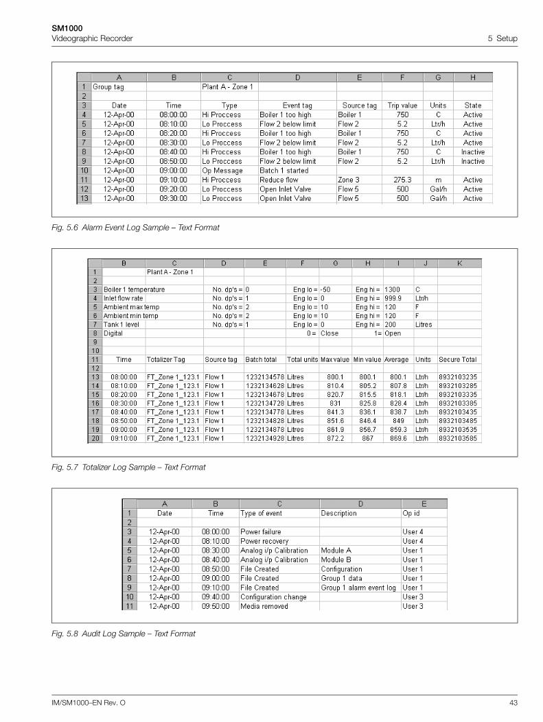
Fig. 5.6 Alarm Event Log Sample – Text Format
Fig. 5.7 Totalizer Log Sample – Text Format
Fig. 5.8 Audit Log Sample – Text Format
SM1000Videographic Recorder 5 Setup
44 IM/SM1000–EN Rev. O
5.7 Binary Format Archive Files
5.7.1 Binary Format Archive FilenamesExamples of binary archive filenames are shown in Table 3.5.
5.7.2 Binary Format Channel Data FilesA new binary format channel data file is created under thefollowing conditions:
When the current file for a channel does not exist on themedia card.
When the maximum size (5Mb) of the existing data file isexceeded.
When the recording channel's configuration is changed.
When the daylight saving period starts or ends.
Files containing channel data generated during the daylightsaving period (summertime) have '~DS' appended to thefilename.
Example 1 – Start of daylight saving period:Archiving is started at 01:45:00 on 30th March 2003 –filename: 01450030Mar03Ch1_1AnlgSM2000.B00.
Summertime starts at 2:00am on 30th March 2003. The clock changes automatically to 3:00am. The existing file is closed and a new file is created –filename:03000030Mar03Ch1_1AnlgSM2000~DS.B00.
The file '01450330Mar03Ch1_1AnlgSM2000.B00' containsdata generated from 01:45:00 to 01:59:59 (beforesummertime starts).
The file '03000030Mar03Ch1_1AnlgSM2000~DS.B00'contains data generated from 03:00:00 (after summertimestarts).
Example 2 – End of daylight saving period:Archiving is started at 00:15:00 on 26th October 2003 –filename: 00150026Oct03Ch1_1AnlgSM2000~DS.B00.
Summertime ends at 3:00am on 26th October 2003.The clock changes automatically to 2:00am.The existing file is closed and a new file is created –filename:02000026Oct03Ch1_1AnlgSM2000.B00.
The file '00150026Oct03Ch1_1AnlgSM2000~DS.D00'contains data generated from 00:15:00 to 02:59:59 (beforesummertime ends).
The file '02000026Oct03Ch1_1AnlgSM2000' contains datagenerated from 02:00:00 (after summertime ends).
5.7.3 Binary Format Log filesA new binary log file is created under the following conditions:
When an existing valid binary log file does not exist on themedia card.
When the maximum size (64000 entries) is exceeded.
When the daylight saving period starts or ends.
Files containing log data generated during the daylight savingperiod (summertime) have “~DS” appended to the filename.
5.7.4 Binary Format Data File ExamplesBinary format archived data is stored in a secure binary encodedformat. A separate file is created for each recording channel.The log data is stored in an encrypted text format. The files canbe read on a PC using the Company's DataManager dataanalysis software package.
5.7.5 Binary Format Data Verification and IntegrityWhen data is saved to the archive media it is checkedautomatically to verify that the data stored on the mediamatches exactly what is stored in the internal memory.
Each block of data in the channel data files has its own dataintegrity check. This enables the integrity of the data stored onthe external media card to be verified when it is viewed using theCompany's DataManager software package.
The log files also contain built-in integrity checks enabling theintegrity of the data to be verified by the DataManager software.
Type Format
Channel data files
<Start Time HHMMSS><Start Date DDMMMYY>Ch<Group>_<Channel><Instrument tag> e.g. 14322719Dec03Ch1_2Boiler room3
Alarm event log files
<Start Time HH_MM><Start Date DDMMMYY><Process Group Tag> e.g. 14_3219Dec03Boiler5
Totalizer log files
<Start Time HH_MM><Start Date DDMMMYY><Process Group Tag> e.g. 14_3219Dec03Boiler5
Audit log files
<Start Time HH_MM><Start Date DDMMMYY><Instrument Tag> e.g. 14_3219Dec03Boiler room 3
Table 5.5 Binary Archive Filenames
Note. The instrument's internal clock can be configured toadjust automatically at the start and end of Daylight SavingTime (Summertime) periods – see Section 6.4.6, page 63.
Note. Binary format archive files created during the daylightsaving period (summertime) are compatible with thedatabase feature of Version 5.8 (or later) only of theCompany's DataManager data analysis software package.
SM1000Videographic Recorder 5 Setup
IM/SM1000–EN Rev. O 45
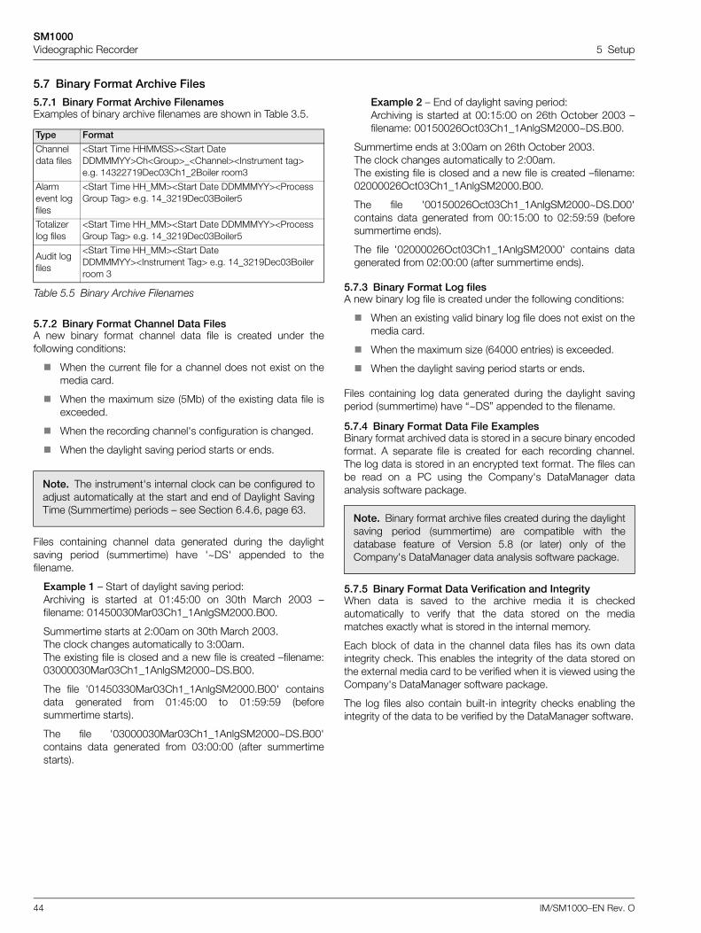
Fig. 5.9 Channel Data File Sample – Binary Format
Fig. 5.10 Alarm Event Log Sample – Binary Format
SM1000Videographic Recorder 5 Setup
46 IM/SM1000–EN Rev. O
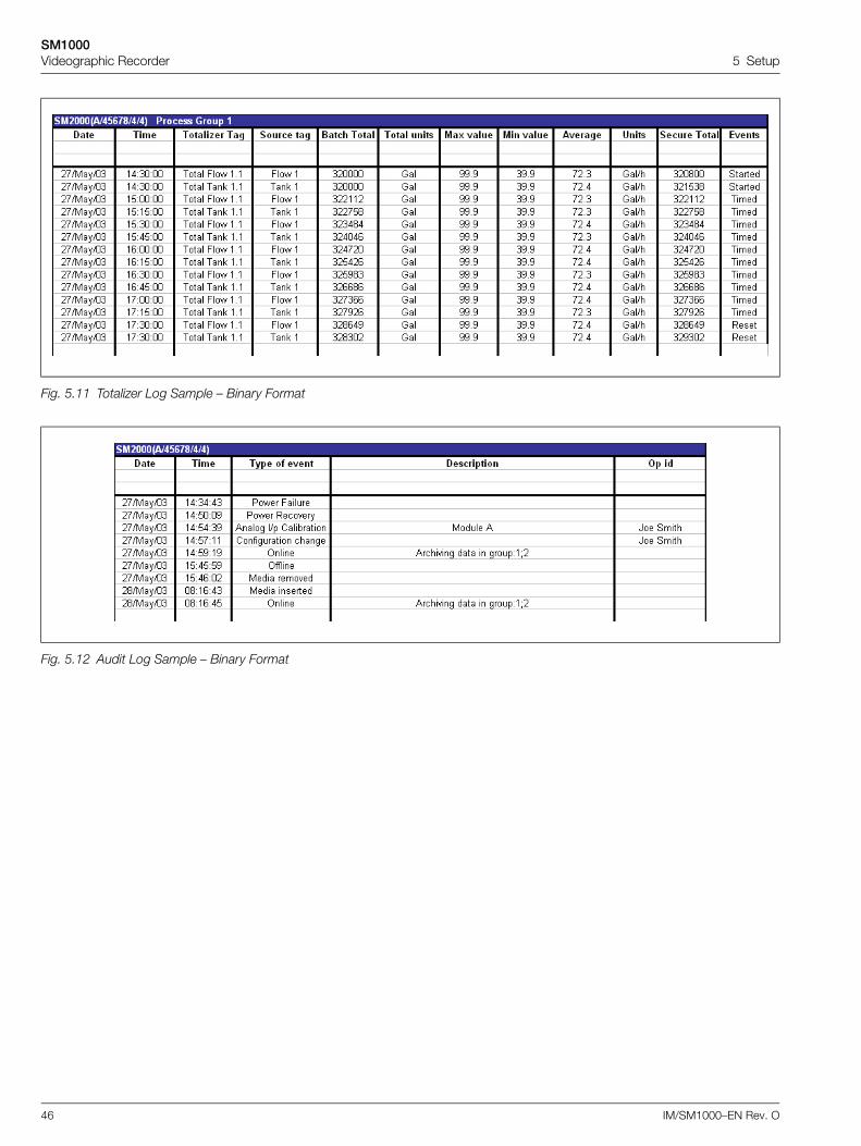
Fig. 5.11 Totalizer Log Sample – Binary Format
Fig. 5.12 Audit Log Sample – Binary Format
SM1000Videographic Recorder 5 Setup
IM/SM1000–EN Rev. O 47
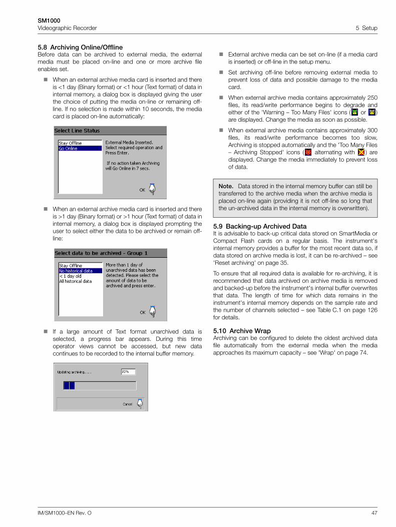
5.8 Archiving Online/OfflineBefore data can be archived to external media, the externalmedia must be placed on-line and one or more archive fileenables set.
When an external archive media card is inserted and thereis <1 day (Binary format) or <1 hour (Text format) of data ininternal memory, a dialog box is displayed giving the userthe choice of putting the media on-line or remaining off-line. If no selection is made within 10 seconds, the mediacard is placed on-line automatically:
When an external archive media card is inserted and thereis >1 day (Binary format) or >1 hour (Text format) of data ininternal memory, a dialog box is displayed prompting theuser to select either the data to be archived or remain off-line:
If a large amount of Text format unarchived data isselected, a progress bar appears. During this timeoperator views cannot be accessed, but new datacontinues to be recorded to the internal buffer memory.
External archive media can be set on-line (if a media cardis inserted) or off-line in the setup menu.
Set archiving off-line before removing external media toprevent loss of data and possible damage to the mediacard.
When external archive media contains approximately 250files, its read/write performance begins to degrade andeither of the 'Warning – Too Many Files' icons ( or )are displayed. Change the media as soon as possible.
When external archive media contains approximately 300files, its read/write performance becomes too slow,Archiving is stopped automatically and the 'Too Many Files– Archiving Stopped' icons ( alternating with ) aredisplayed. Change the media immediately to prevent lossof data.
5.9 Backing-up Archived DataIt is advisable to back-up critical data stored on SmartMedia orCompact Flash cards on a regular basis. The instrument'sinternal memory provides a buffer for the most recent data so, ifdata stored on archive media is lost, it can be re-archived – see'Reset archiving' on page 35.
To ensure that all required data is available for re-archiving, it isrecommended that data archived on archive media is removedand backed-up before the instrument's internal buffer overwritesthat data. The length of time for which data remains in theinstrument's internal memory depends on the sample rate andthe number of channels selected – see Table C.1 on page 126for details.
5.10 Archive WrapArchiving can be configured to delete the oldest archived datafile automatically from the external media when the mediaapproaches its maximum capacity – see 'Wrap' on page 74.
Note. Data stored in the internal memory buffer can still betransferred to the archive media when the archive media isplaced on-line again (providing it is not off-line so long thatthe un-archived data in the internal memory is overwritten).
SM1000Videographic Recorder 6 Configuration
48 IM/SM1000–EN Rev. O
6 Configuration6.1 IntroductionThis section details the configuration of the instrument locallyusing the front panel membrane keys. A configuration file canalso be created on a PC and transferred to the instrument viaone of the archive media options.
In addition, up to 16 different configurations can be stored ininternal memory and restored when required.
6.1.1 Configuration Level SecurityTwo methods of configuration access protection are available:
1. Password protection (Factory Default).The Configuration level cannot be accessed until the correctpassword has been entered – see Fig. 6.1, page 49.
2. Internal switch protection.The Configuration level cannot be accessed until theinstrument is withdrawn from its case and the internalswitch set to the 'Configuration Level Not Protected'position – see Fig. 6.2, page 50.
The instrument can be configured for one of two levels ofpassword protection:
Basic Security: Up to 4 users Each user is assigned a unique 4-digit security code for
Configuration level access Optional security code protection of access to Setup level
Advanced Security: Up to 12 users Each user is assigned a unique password of up to 20
characters Each user is assigned configuration, setup and/or
electronic signature access privileges Each user is assigned one of 3 levels of configuration level
access privileges Configurable password expiry times, password failure
limits and minimum password length Inactive user disabling
6.1.2 Configuration Level AccessTo configure an instrument when 'Configuration security type' isset to the factory default setting of 'Password protected':
Access the Configuration Level – see Fig. 6.1, page 49.
Make changes to parameters as detailed in Figs. 6.1 and 6.3.
To configure an instrument when 'Configuration security type' isset to 'Internal switch protected':
Set the internal security switch to the 'Configuration LevelNot Protected' position – see Fig. 6.2, page 50.
Access the Configuration Level – see Fig. 6.1, page 49.
Make changes to parameters as detailed in Figs. 6.1 and 6.3.
'Configuration security' Parameter Setting
(see Section 6.4.4, page 59)
Internal Security Switch Setting
(see Fig. 6.2, page 50)
'Password protected'
(Factory Default)
'Internal switch protected' (Alternative)
Configuration Level Protected
(Factory Default)Password Access No Access
Configuration Level Not Protected
Free Access Free Access
Note. The electronic signature feature is available only withAdvanced security.
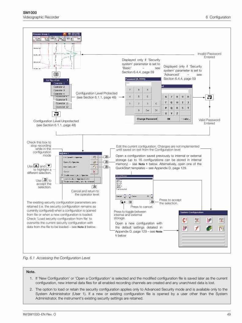
SM1000Videographic Recorder 6 Configuration
IM/SM1000–EN Rev. O 49
Fig. 6.1 Accessing the Configuration Level
Note.
1. If 'New Configuration' or 'Open a Configuration' is selected and the modified configuration file is saved later as the currentconfiguration, new internal data files for all enabled recording channels are created and any unarchived data is lost.
2. The option to load or retain the security configuration applies only to Advanced Security mode and is available only to theSystem Administrator (User 1). If a new or existing configuration file is opened by a user other than the SystemAdministrator, the instrument's existing security settings are retained.
0�� �� ����� ����������" ������ ��� � ������������ �� �� � �.� ���� �� ���������� �� ��
����� �� ���� ��� ������� �� ��
,�� �.���� ������� ���������� ��������� ��������� ��"�" �� ������� ���������� ������ ��������� ���������� ��� � ���������� �� ��������� ���� �� ��� � �� ���������� �� ������"����< 71��� ������� ���������� ���� ����7 �� ������ �� ����� ������� ���������� ������ ���� �� ���� � *� ������ : ��� ���� *����"
4���� 5�������0����
� ���� 5�������0����
5���� � ������� �������"
5���� � ����� *��������� �� �.����������"
5���� � �����"
?�� �� � �������� �
������� �������"
?�� ������ ���������"
����< ��� *�. ���� ��������
����� � ������������
����
Displayed only if 'Securitysystem' parameter is set to'Basic' – seeSection 6.4.4, page 59
Displayed only if 'Securitysystem' parameter is set to'Advanced' – seeSection 6.4.4, page 59
Configuration Level Protected (see Section 6.1.1, page 48)
Configuration Level Unprotected (see Section 6.1.1, page 48)
Open a configuration saved previously to internal or externalstorage (up to 16 configurations can be stored in internalmemory) – see Note 1 below. Alternatively, open one of theQuickStart templates – see Appendix D, page 129.
Open a new configuration withthe default settings detailed inAppendix D, page 129 – see Note1 below
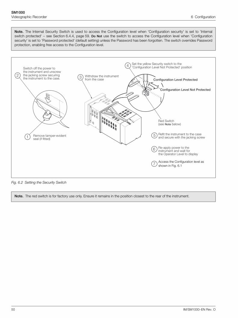
SM1000Videographic Recorder 6 Configuration
50 IM/SM1000–EN Rev. O
Note. The Internal Security Switch is used to access the Configuration level when 'Configuration security' is set to 'Internalswitch protected' – see Section 6.4.4, page 59. Do Not use the switch to access the Configuration level when 'Configurationsecurity' is set to 'Password protected' (default setting) unless the Password has been forgotten. The switch overrides Passwordprotection, enabling free access to the Configuration level.
Fig. 6.2 Setting the Security Switch
Note. The red switch is for factory use only. Ensure it remains in the position closest to the rear of the instrument.
K������ �� ���������� �� ����
���� � �����8� ������� ��� �����
����� ��� �� ����� ��� ������ �� �������� G��<�� ����� ��������� ������ � �� ����"
�� �� ������ ������� ����� � ��7���������� 1� �� 9� 5������7 ������
,��0� ��������������������
,��0� �����������������
�
! #
$
��� ��������� ��� *�����
��8����� ����� � �������� �� ��� ����� >������ 1� �� � �������
%
&
���� �� ������ � �� ������ ������ ��� �� G��<�� �����
BAccess the Configuration level as shown in Fig. 6.1
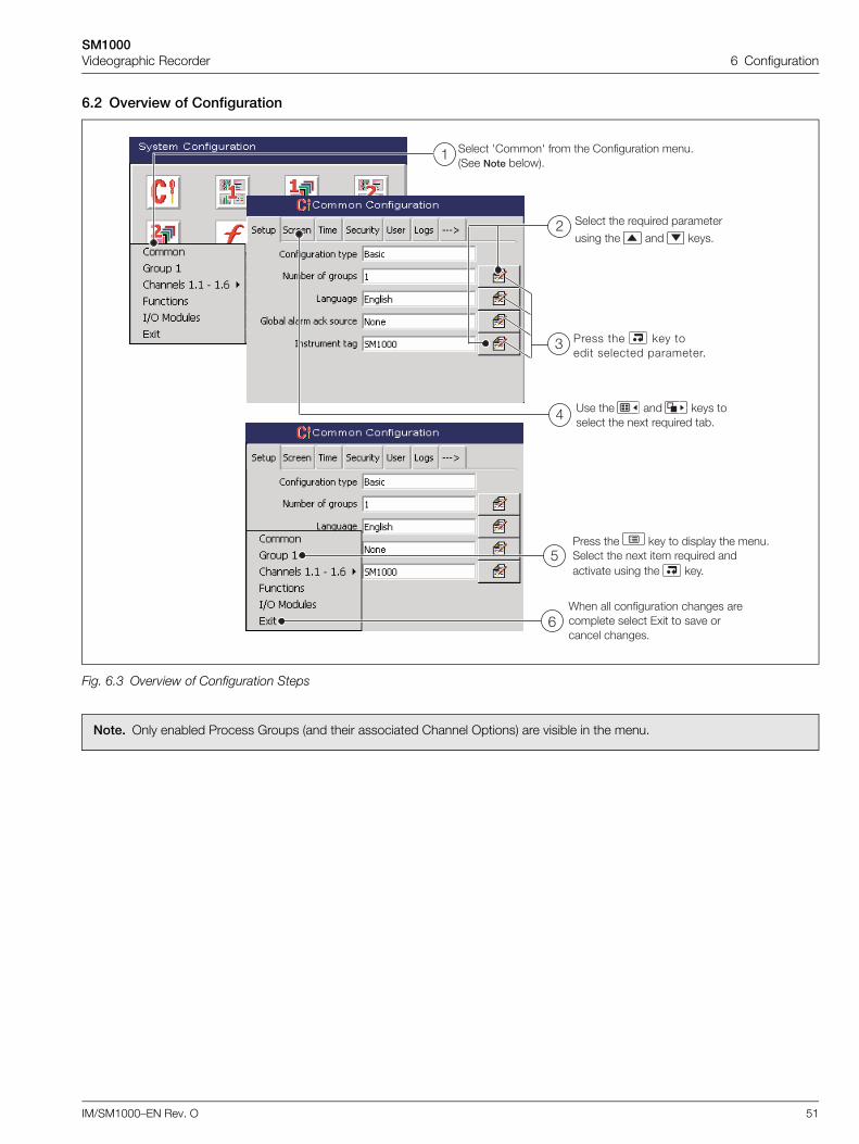
SM1000Videographic Recorder 6 Configuration
IM/SM1000–EN Rev. O 51
6.2 Overview of Configuration
Fig. 6.3 Overview of Configuration Steps
Note. Only enabled Process Groups (and their associated Channel Options) are visible in the menu.
����� 7�����7 ���� �� ���������� ���"���� ��� *�����"
�
����� �� ��M����� ��������
���� �� �� <���"
5���� �� <�� ���� ������� ��������"
?�� �� �� <��� ������ �� �. ��M����� �*"$
!
#
K�� ��� ���������� ������ ���������� ����� 0.� � �� � ������� ������"
5���� �� <�� � ������� �� ���"����� �� �. ��� ��M����� ����� �� ���� �� <��"
%
&
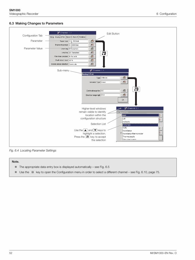
SM1000Videographic Recorder 6 Configuration
52 IM/SM1000–EN Rev. O
6.3 Making Changes to Parameters
Fig. 6.4 Locating Parameter Settings
Note.
The appropriate data entry box is displayed automatically – see Fig. 6.5
Use the key to open the Configuration menu in order to select a different channel – see Fig. 6.10, page 75.
5������� 4����
��*8���
0�� (������������ ,�*
������� 1��
;�����8�� �� ����������� ���*�� � ������
������ ���� ������������ �������
5�������
?�� �� �� <��� ��������� � �������"
5���� �� <�� � ������� �������
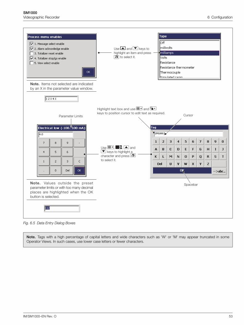
SM1000Videographic Recorder 6 Configuration
IM/SM1000–EN Rev. O 53
Fig. 6.5 Data Entry Dialog Boxes
Note. Tags with a high percentage of capital letters and wide characters such as 'W' or 'M' may appear truncated in someOperator Views. In such cases, use lower case letters or fewer characters.
������5������� 1����
;������� �. *�. �� ��� �� <��� � ������ ������ � ��� �. �� ��M�����"
�����*������ 4����� ������ �� ������������� ����� �� ��� �� ��� ������������� ��� ���������� ��� �� >�*�� �� �������"
?�� �� <��� ��������� � ��� �� �����
� ����� �"
���� ���� � ������� ��� �������*� � N � �� �������� ���� �����"
?�� - - �� <��� � �������� �
�������� �� ����� � ����� �"
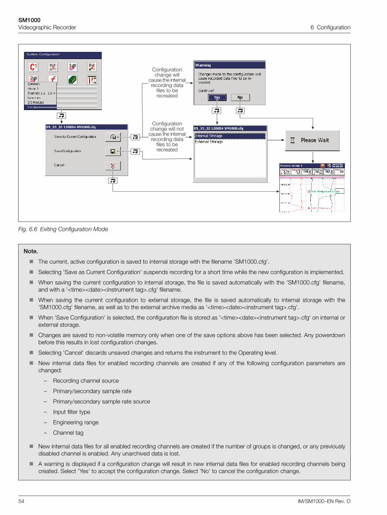
SM1000Videographic Recorder 6 Configuration
54 IM/SM1000–EN Rev. O
Fig. 6.6 Exiting Configuration Mode
Note.
The current, active configuration is saved to internal storage with the filename 'SM1000.cfg'.
Selecting 'Save as Current Configuration' suspends recording for a short time while the new configuration is implemented.
When saving the current configuration to internal storage, the file is saved automatically with the 'SM1000.cfg' filename,and with a '<time><date><instrument tag>.cfg' filename.
When saving the current configuration to external storage, the file is saved automatically to internal storage with the'SM1000.cfg' filename, as well as to the external archive media as '<time><date><instrument tag>.cfg'.
When 'Save Configuration' is selected, the configuration file is stored as '<time><date><instrument tag>.cfg' on internal orexternal storage.
Changes are saved to non-volatile memory only when one of the save options above has been selected. Any powerdownbefore this results in lost configuration changes.
Selecting 'Cancel' discards unsaved changes and returns the instrument to the Operating level.
New internal data files for enabled recording channels are created if any of the following configuration parameters arechanged:
– Recording channel source
– Primary/secondary sample rate
– Primary/secondary sample rate source
– Input filter type
– Engineering range
– Channel tag
New internal data files for all enabled recording channels are created if the number of groups is changed, or any previouslydisabled channel is enabled. Any unarchived data is lost.
A warning is displayed if a configuration change will result in new internal data files for enabled recording channels beingcreated. Select 'Yes' to accept the configuration change. Select 'No' to cancel the configuration change.
��������������� ���� ������ �� ������������� ���
����� � *���������
��������������� ����
����� �� ������������� ���
����� � *���������
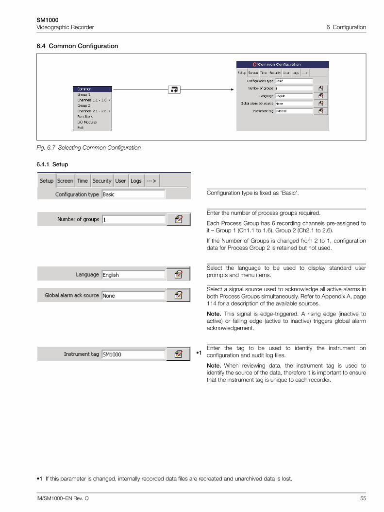
SM1000Videographic Recorder 6 Configuration
IM/SM1000–EN Rev. O 55
6.4 Common Configuration
6.4.1 Setup
Fig. 6.7 Selecting Common Configuration
Configuration type is fixed as 'Basic'.
Enter the number of process groups required.
Each Process Group has 6 recording channels pre-assigned toit – Group 1 (Ch1.1 to 1.6), Group 2 (Ch2.1 to 2.6).
If the Number of Groups is changed from 2 to 1, configurationdata for Process Group 2 is retained but not used.
Select the language to be used to display standard userprompts and menu items.
Select a signal source used to acknowledge all active alarms inboth Process Groups simultaneously. Refer to Appendix A, page114 for a description of the available sources.
Note. This signal is edge-triggered. A rising edge (inactive toactive) or falling edge (active to inactive) triggers global alarmacknowledgement.
Enter the tag to be used to identify the instrument onconfiguration and audit log files.
Note. When reviewing data, the instrument tag is used toidentify the source of the data, therefore it is important to ensurethat the instrument tag is unique to each recorder.
•1 If this parameter is changed, internally recorded data files are recreated and unarchived data is lost.
9�
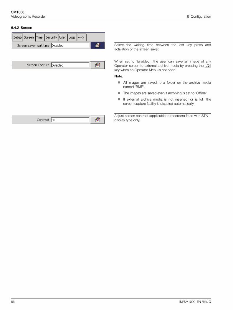
SM1000Videographic Recorder 6 Configuration
56 IM/SM1000–EN Rev. O
6.4.2 Screen
Select the waiting time between the last key press andactivation of the screen saver.
When set to 'Enabled', the user can save an image of anyOperator screen to external archive media by pressing the key when an Operator Menu is not open.
Note.
All images are saved to a folder on the archive medianamed 'BMP'.
The images are saved even if archiving is set to 'Offline'.
If external archive media is not inserted, or is full, thescreen capture facility is disabled automatically.
Adjust screen contrast (applicable to recorders fitted with STN display type only).
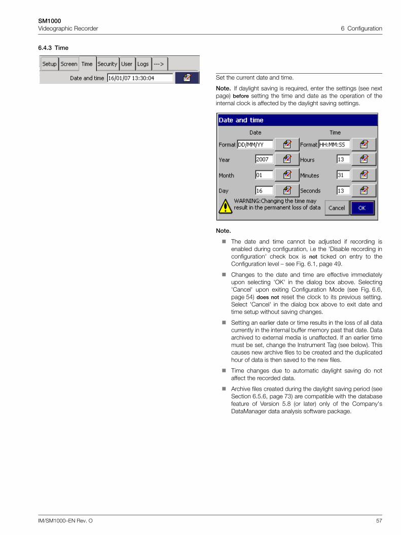
SM1000Videographic Recorder 6 Configuration
IM/SM1000–EN Rev. O 57
6.4.3 Time
Set the current date and time.
Note. If daylight saving is required, enter the settings (see nextpage) before setting the time and date as the operation of theinternal clock is affected by the daylight saving settings.
Note.
The date and time cannot be adjusted if recording isenabled during configuration, i.e the 'Disable recording inconfiguration' check box is not ticked on entry to theConfiguration level – see Fig. 6.1, page 49.
Changes to the date and time are effective immediatelyupon selecting 'OK' in the dialog box above. Selecting'Cancel' upon exiting Configuration Mode (see Fig. 6.6,page 54) does not reset the clock to its previous setting.Select 'Cancel' in the dialog box above to exit date andtime setup without saving changes.
Setting an earlier date or time results in the loss of all datacurrently in the internal buffer memory past that date. Dataarchived to external media is unaffected. If an earlier timemust be set, change the Instrument Tag (see below). Thiscauses new archive files to be created and the duplicatedhour of data is then saved to the new files.
Time changes due to automatic daylight saving do notaffect the recorded data.
Archive files created during the daylight saving period (seeSection 6.5.6, page 73) are compatible with the databasefeature of Version 5.8 (or later) only of the Company'sDataManager data analysis software package.
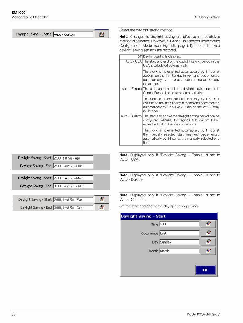
SM1000Videographic Recorder 6 Configuration
58 IM/SM1000–EN Rev. O
Select the daylight saving method.
Note. Changes to daylight saving are effective immediately amethod is selected. However, if 'Cancel' is selected upon exitingConfiguration Mode (see Fig. 6.6, page 54), the last saveddaylight saving settings are restored.
Off Daylight saving is disabled.
Auto - USA The start and end of the daylight saving period in theUSA is calculated automatically.
The clock is incremented automatically by 1 hour at2:00am on the first Sunday in April and decrementedautomatically by 1 hour at 2:00am on the last Sundayin October.
Auto - Europe The start and end of the daylight saving period inCentral Europe is calculated automatically.
The clock is incremented automatically by 1 hour at2:00am on the last Sunday in March and decrementedautomatically by 1 hour at 2:00am on the last Sundayin October.
Auto - Custom The start and end of the daylight saving period can beconfigured manually for regions that do not followeither the USA or Europe conventions.
The clock is incremented automatically by 1 hour atthe manually selected start time and decrementedautomatically by 1 hour at the manually selected endtime.
Note. Displayed only if 'Daylight Saving - Enable' is set to'Auto - USA'.
Note. Displayed only if 'Daylight Saving - Enable' is set to'Auto - Europe'.
Note. Displayed only if 'Daylight Saving - Enable' is set to'Auto - Custom'.
Set the start and end of the daylight saving period.
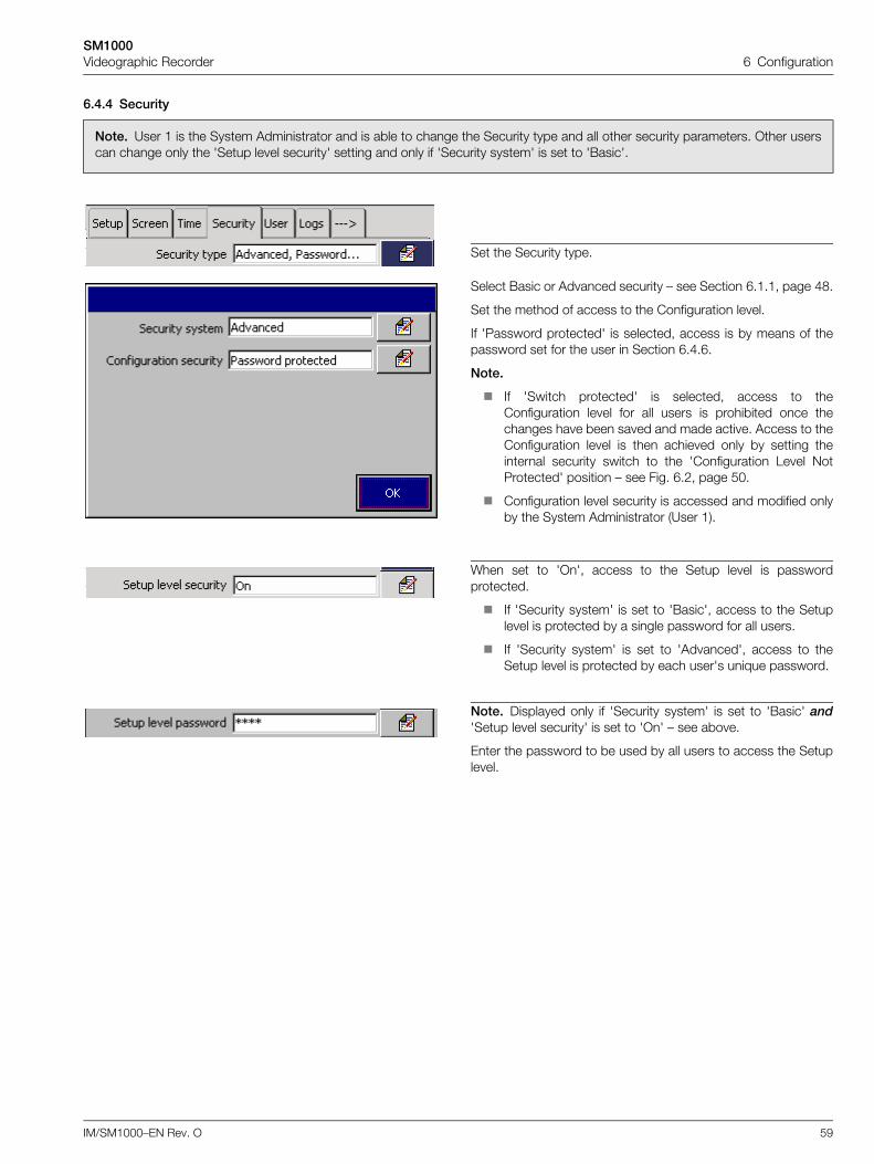
SM1000Videographic Recorder 6 Configuration
IM/SM1000–EN Rev. O 59
6.4.4 Security
Note. User 1 is the System Administrator and is able to change the Security type and all other security parameters. Other userscan change only the 'Setup level security' setting and only if 'Security system' is set to 'Basic'.
Set the Security type.
Select Basic or Advanced security – see Section 6.1.1, page 48.
Set the method of access to the Configuration level.
If 'Password protected' is selected, access is by means of thepassword set for the user in Section 6.4.6.
Note.
If 'Switch protected' is selected, access to theConfiguration level for all users is prohibited once thechanges have been saved and made active. Access to theConfiguration level is then achieved only by setting theinternal security switch to the 'Configuration Level NotProtected' position – see Fig. 6.2, page 50.
Configuration level security is accessed and modified onlyby the System Administrator (User 1).
When set to 'On', access to the Setup level is passwordprotected.
If 'Security system' is set to 'Basic', access to the Setuplevel is protected by a single password for all users.
If 'Security system' is set to 'Advanced', access to theSetup level is protected by each user's unique password.
Note. Displayed only if 'Security system' is set to 'Basic' and'Setup level security' is set to 'On' – see above.
Enter the password to be used by all users to access the Setuplevel.
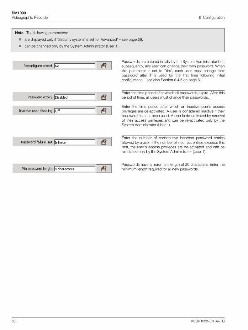
SM1000Videographic Recorder 6 Configuration
60 IM/SM1000–EN Rev. O
Note. The following parameters:
are displayed only if 'Security system' is set to 'Advanced' – see page 59.
can be changed only by the System Administrator (User 1).
Passwords are entered initially by the System Administrator but,subsequently, any user can change their own password. Whenthis parameter is set to 'Yes', each user must change theirpassword after it is used for the first time following initialconfiguration – see also Section 6.4.5 on page 61.
Enter the time period after which all passwords expire. After thisperiod of time, all users must change their passwords.
Enter the time period after which an inactive user's accessprivileges are de-activated. A user is considered inactive if theirpassword has not been used. A user is de-activated by removalof their access privileges and can be re-activated only by theSystem Administrator (User 1).
Enter the number of consecutive incorrect password entriesallowed by a user. If the number of incorrect entries exceeds thislimit, the user's access privileges are de-activated and can bereinstated only by the System Administrator (User 1).
Passwords have a maximum length of 20 characters. Enter theminimum length required for all new passwords.
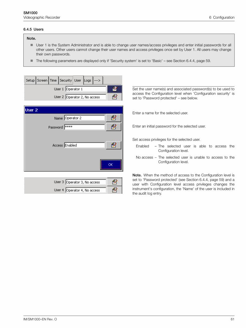
SM1000Videographic Recorder 6 Configuration
IM/SM1000–EN Rev. O 61
6.4.5 Users
Note.
User 1 is the System Administrator and is able to change user names/access privileges and enter initial passwords for allother users. Other users cannot change their user names and access privileges once set by User 1. All users may changetheir own passwords.
The following parameters are displayed only if 'Security system' is set to 'Basic' – see Section 6.4.4, page 59.
Set the user name(s) and associated password(s) to be used toaccess the Configuration level when 'Configuration security' isset to 'Password protected' – see below.
Enter a name for the selected user.
Enter an initial password for the selected user.
Set access privileges for the selected user.
Enabled – The selected user is able to access theConfiguration level.
No access – The selected user is unable to access to theConfiguration level.
Note. When the method of access to the Configuration level isset to 'Password protected' (see Section 6.4.4, page 59) and auser with Configuration level access privileges changes theinstrument's configuration, the 'Name' of the user is included inthe audit log entry.
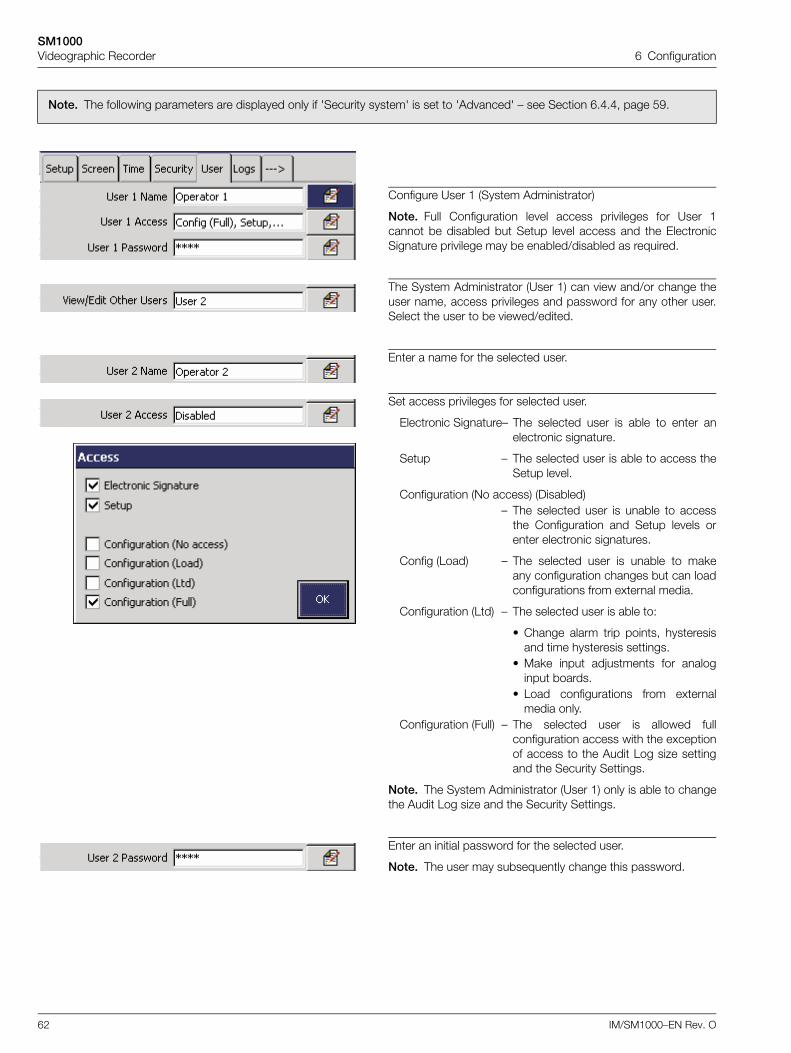
SM1000Videographic Recorder 6 Configuration
62 IM/SM1000–EN Rev. O
Note. The following parameters are displayed only if 'Security system' is set to 'Advanced' – see Section 6.4.4, page 59.
Configure User 1 (System Administrator)
Note. Full Configuration level access privileges for User 1cannot be disabled but Setup level access and the ElectronicSignature privilege may be enabled/disabled as required.
The System Administrator (User 1) can view and/or change theuser name, access privileges and password for any other user.Select the user to be viewed/edited.
Enter a name for the selected user.
Set access privileges for selected user.
Electronic Signature– The selected user is able to enter anelectronic signature.
Setup – The selected user is able to access theSetup level.
Configuration (No access) (Disabled)– The selected user is unable to access
the Configuration and Setup levels orenter electronic signatures.
Config (Load) – The selected user is unable to makeany configuration changes but can loadconfigurations from external media.
Configuration (Ltd) – The selected user is able to:
• Change alarm trip points, hysteresisand time hysteresis settings.
• Make input adjustments for analoginput boards.
• Load configurations from externalmedia only.
Configuration (Full) – The selected user is allowed fullconfiguration access with the exceptionof access to the Audit Log size settingand the Security Settings.
Note. The System Administrator (User 1) only is able to changethe Audit Log size and the Security Settings.
Enter an initial password for the selected user.
Note. The user may subsequently change this password.
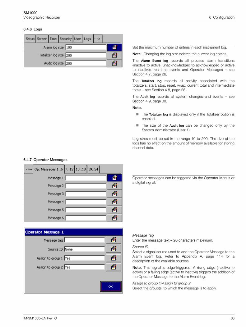
SM1000Videographic Recorder 6 Configuration
IM/SM1000–EN Rev. O 63
6.4.6 Logs
6.4.7 Operator Messages
Set the maximum number of entries in each instrument log.
Note. Changing the log size deletes the current log entries.
The Alarm Event log records all process alarm transitions(inactive to active, unacknowledged to acknowledged or activeto inactive), real-time events and Operator Messages – seeSection 4.7, page 26.
The Totalizer log records all activity associated with thetotalizers: start, stop, reset, wrap, current total and intermediatetotals – see Section 4.8, page 28.
The Audit log records all system changes and events – seeSection 4.9, page 30.
Note.
The Totalizer log is displayed only if the Totalizer option isenabled.
The size of the Audit log can be changed only by theSystem Administrator (User 1).
Log sizes must be set in the range 10 to 200. The size of thelogs has no effect on the amount of memory available for storingchannel data.
Operator messages can be triggered via the Operator Menus ora digital signal.
Message TagEnter the message text – 20 characters maximum.
Source IDSelect a signal source used to add the Operator Message to theAlarm Event log. Refer to Appendix A, page 114 for adescription of the available sources.
Note. This signal is edge-triggered. A rising edge (inactive toactive) or a falling edge (active to inactive) triggers the addition ofthe Operator Message to the Alarm Event log.
Assign to group 1/Assign to group 2Select the group(s) to which the message is to apply.
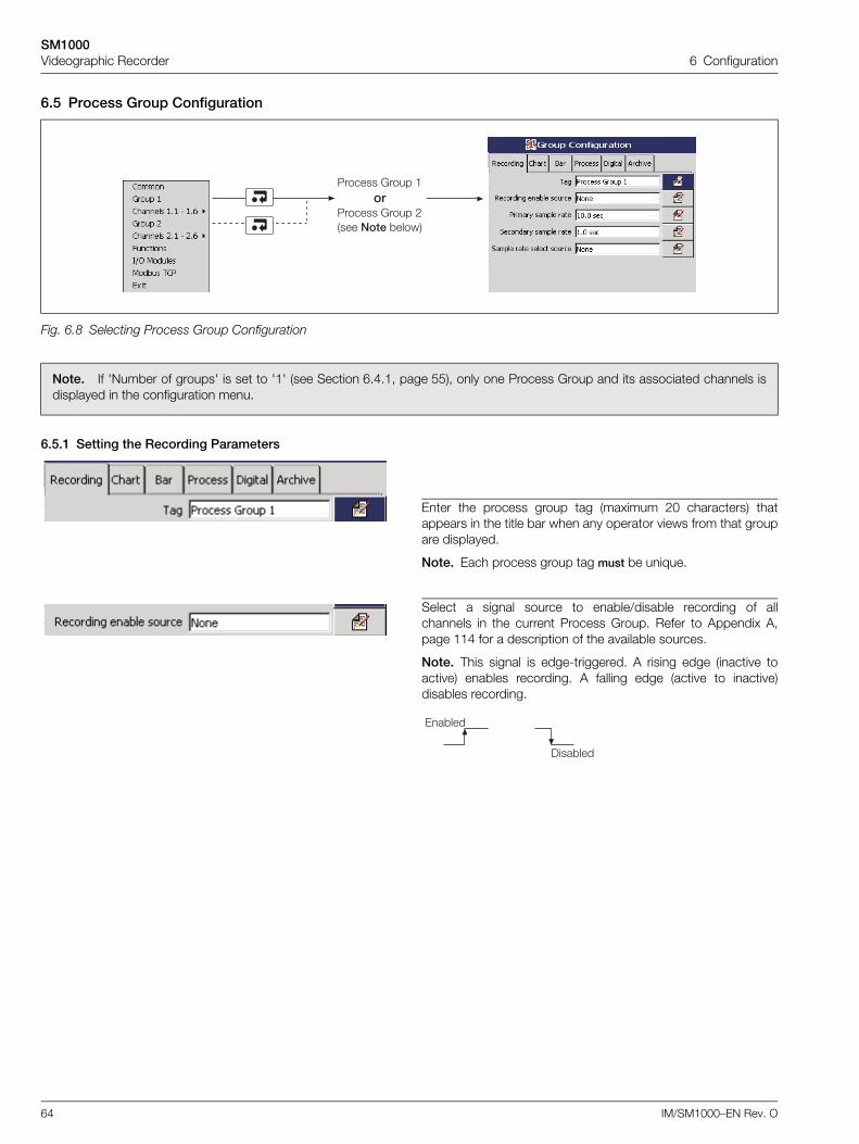
SM1000Videographic Recorder 6 Configuration
64 IM/SM1000–EN Rev. O
6.5 Process Group Configuration
6.5.1 Setting the Recording Parameters
Fig. 6.8 Selecting Process Group Configuration
Note. If 'Number of groups' is set to '1' (see Section 6.4.1, page 55), only one Process Group and its associated channels isdisplayed in the configuration menu.
Enter the process group tag (maximum 20 characters) thatappears in the title bar when any operator views from that groupare displayed.
Note. Each process group tag must be unique.
Select a signal source to enable/disable recording of allchannels in the current Process Group. Refer to Appendix A,page 114 for a description of the available sources.
Note. This signal is edge-triggered. A rising edge (inactive toactive) enables recording. A falling edge (active to inactive)disables recording.
5������ 6���� ���
5������ 6���� !���� ��� *�����
)���*���
0�*���
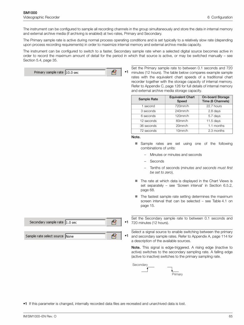
SM1000Videographic Recorder 6 Configuration
IM/SM1000–EN Rev. O 65
The instrument can be configured to sample all recording channels in the group simultaneously and store the data in internal memoryand external archive media (if archiving is enabled) at two rates, Primary and Secondary.
The Primary sample rate is active during normal process operating conditions and is set typically to a relatively slow rate (dependingupon process recording requirements) in order to maximize internal memory and external archive media capacity.
The instrument can be configured to switch to a faster, Secondary sample rate when a selected digital source becomes active inorder to record the maximum amount of detail for the period in which that source is active, or may be switched manually – seeSection 5.4, page 35.
Set the Primary sample rate to between 0.1 seconds and 720minutes (12 hours). The table below compares example samplerates with the equivalent chart speeds of a traditional chartrecorder together with the storage capacity of internal memory.Refer to Appendix C, page 126 for full details of internal memoryand external archive media storage capacity.
Sample RateEquivalent Chart
SpeedOn-board Storage Time (6 Channels)
1 second 720mm/h 22.7 hours
3 seconds 240mm/h 2.8 days
6 seconds 120mm/h 5.7 days
12 seconds 60mm/h 11.5 days
36 seconds 20mm/h 1.1 months
72 seconds 10mm/h 2.3 months
Note.
Sample rates are set using one of the followingcombinations of units:
– Minutes or minutes and seconds
– Seconds
– Tenths of seconds (minutes and seconds must firstbe set to zero).
The rate at which data is displayed in the Chart Views isset separately – see 'Screen interval' in Section 6.5.2,page 68.
The fastest sample rate setting determines the maximumscreen interval that can be selected – see Table 4.1 onpage 15.
Set the Secondary sample rate to between 0.1 seconds and720 minutes (12 hours).
Select a signal source to enable switching between the primaryand secondary sample rates. Refer to Appendix A, page 114 fora description of the available sources.
Note. This signal is edge-triggered. A rising edge (inactive toactive) switches to the secondary sampling rate. A falling edge(active to inactive) switches to the primary sampling rate.
•1 If this parameter is changed, internally recorded data files are recreated and unarchived data is lost.
9�
9�
9�
5������
��������
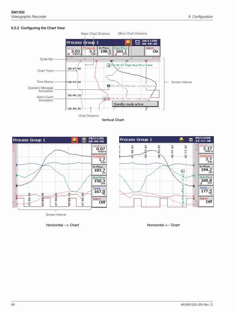
SM1000Videographic Recorder 6 Configuration
66 IM/SM1000–EN Rev. O
6.5.2 Configuring the Chart View
����� ��� ��
����� (��
'���� 0 �'����
>������ �������'����
����� ��� ��,��� ����
���� ,����
���� )� �����
7���$�����::;,'��� 7���$�����<::,'���
)������,'���
��G�� ���� )� ����� ���� ���� )� �����
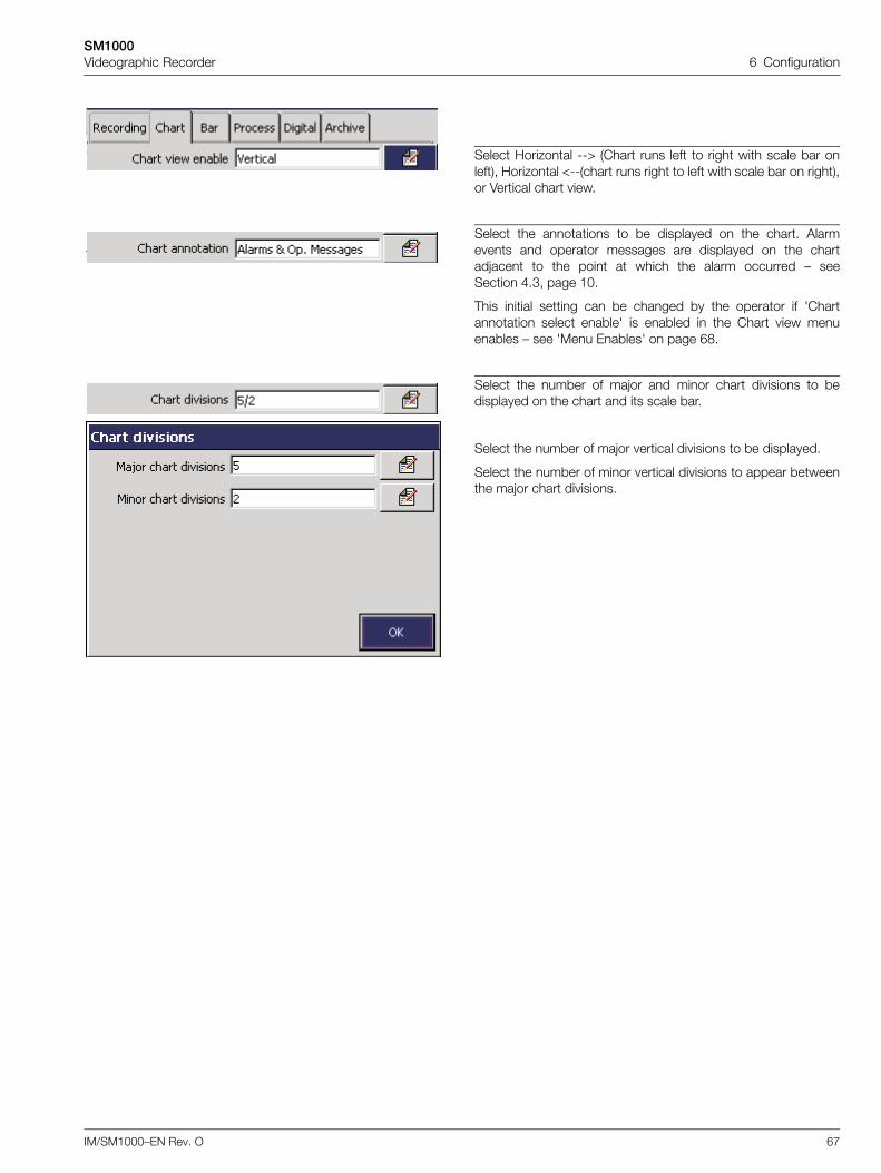
SM1000Videographic Recorder 6 Configuration
IM/SM1000–EN Rev. O 67
Select Horizontal --> (Chart runs left to right with scale bar onleft), Horizontal <--(chart runs right to left with scale bar on right),or Vertical chart view.
Select the annotations to be displayed on the chart. Alarmevents and operator messages are displayed on the chartadjacent to the point at which the alarm occurred – seeSection 4.3, page 10.
This initial setting can be changed by the operator if 'Chartannotation select enable' is enabled in the Chart view menuenables – see 'Menu Enables' on page 68.
Select the number of major and minor chart divisions to bedisplayed on the chart and its scale bar.
Select the number of major vertical divisions to be displayed.
Select the number of minor vertical divisions to appear betweenthe major chart divisions.
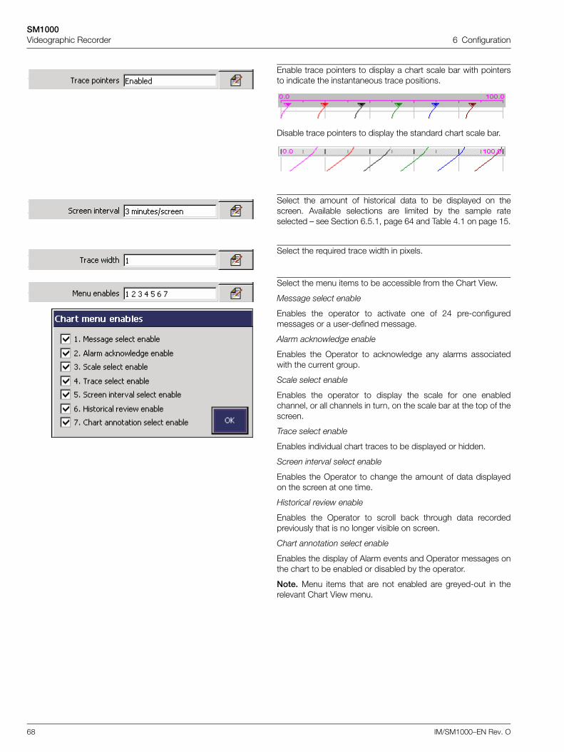
SM1000Videographic Recorder 6 Configuration
68 IM/SM1000–EN Rev. O
Enable trace pointers to display a chart scale bar with pointersto indicate the instantaneous trace positions.
Disable trace pointers to display the standard chart scale bar.
Select the amount of historical data to be displayed on thescreen. Available selections are limited by the sample rateselected – see Section 6.5.1, page 64 and Table 4.1 on page 15.
Select the required trace width in pixels.
Select the menu items to be accessible from the Chart View.
Message select enable
Enables the operator to activate one of 24 pre-configuredmessages or a user-defined message.
Alarm acknowledge enable
Enables the Operator to acknowledge any alarms associatedwith the current group.
Scale select enable
Enables the operator to display the scale for one enabledchannel, or all channels in turn, on the scale bar at the top of thescreen.
Trace select enable
Enables individual chart traces to be displayed or hidden.
Screen interval select enable
Enables the Operator to change the amount of data displayedon the screen at one time.
Historical review enable
Enables the Operator to scroll back through data recordedpreviously that is no longer visible on screen.
Chart annotation select enable
Enables the display of Alarm events and Operator messages onthe chart to be enabled or disabled by the operator.
Note. Menu items that are not enabled are greyed-out in therelevant Chart View menu.
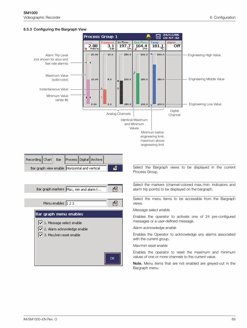
SM1000Videographic Recorder 6 Configuration
IM/SM1000–EN Rev. O 69
6.5.3 Configuring the Bargraph View
Select the Bargraph views to be displayed in the currentProcess Group.
Select the markers (channel-colored max./min. indicators andalarm trip points) to be displayed on the bargraph.
Select the menu items to be accessible from the Bargraphviews.
Message select enable
Enables the operator to activate one of 24 pre-configuredmessages or a user-defined message.
Alarm acknowledge enable
Enables the Operator to acknowledge any alarms associatedwith the current group.
Max/min reset enable
Enables the operator to reset the maximum and minimumvalues of one or more channels to the current value.
Note. Menu items that are not enabled are greyed-out in theBargraph menu.
'���� ,��� 1� ���� ���� ��� ���� ��
��� ��� �������
'���� ������)�����
�����
��.���� 4���������� ������
������ 4��������� �����
�������� 4����
0������� ������ 4����
0������� ;��� 4����
0������� 1�� 4����
������� ��.������ ������
4����������� *������������ ����-��.���� �*� ��������� ����
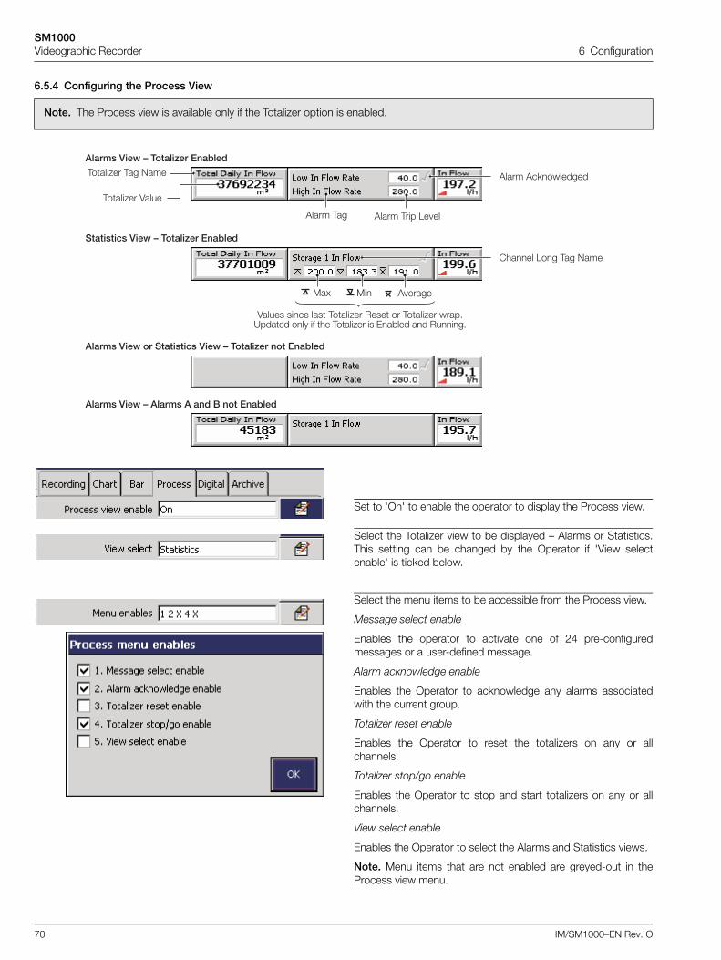
SM1000Videographic Recorder 6 Configuration
70 IM/SM1000–EN Rev. O
6.5.4 Configuring the Process View
Note. The Process view is available only if the Totalizer option is enabled.
Set to 'On' to enable the operator to display the Process view.
Select the Totalizer view to be displayed – Alarms or Statistics.This setting can be changed by the Operator if 'View selectenable' is ticked below.
Select the menu items to be accessible from the Process view.
Message select enable
Enables the operator to activate one of 24 pre-configuredmessages or a user-defined message.
Alarm acknowledge enable
Enables the Operator to acknowledge any alarms associatedwith the current group.
Totalizer reset enable
Enables the Operator to reset the totalizers on any or allchannels.
Totalizer stop/go enable
Enables the Operator to stop and start totalizers on any or allchannels.
View select enable
Enables the Operator to select the Alarms and Statistics views.
Note. Menu items that are not enabled are greyed-out in theProcess view menu.
������)�*������������)�*6#�����$�������=��
������)�*6����������(������=��
'���� ,��
,����2�� ,�� 9���
,����2�� 4����
������)�*6#�����$����=��
'���� ,��� 1� ��
'���� '�<��������
����� 1�� ,�� 9���
����������)�*6#�����$����=��
4����� ���� ��� ,����2�� ���� �� ,����2�� ����"?����� ��� �� �� ,����2�� �� 0�*��� �� ����"
�� ' �������.
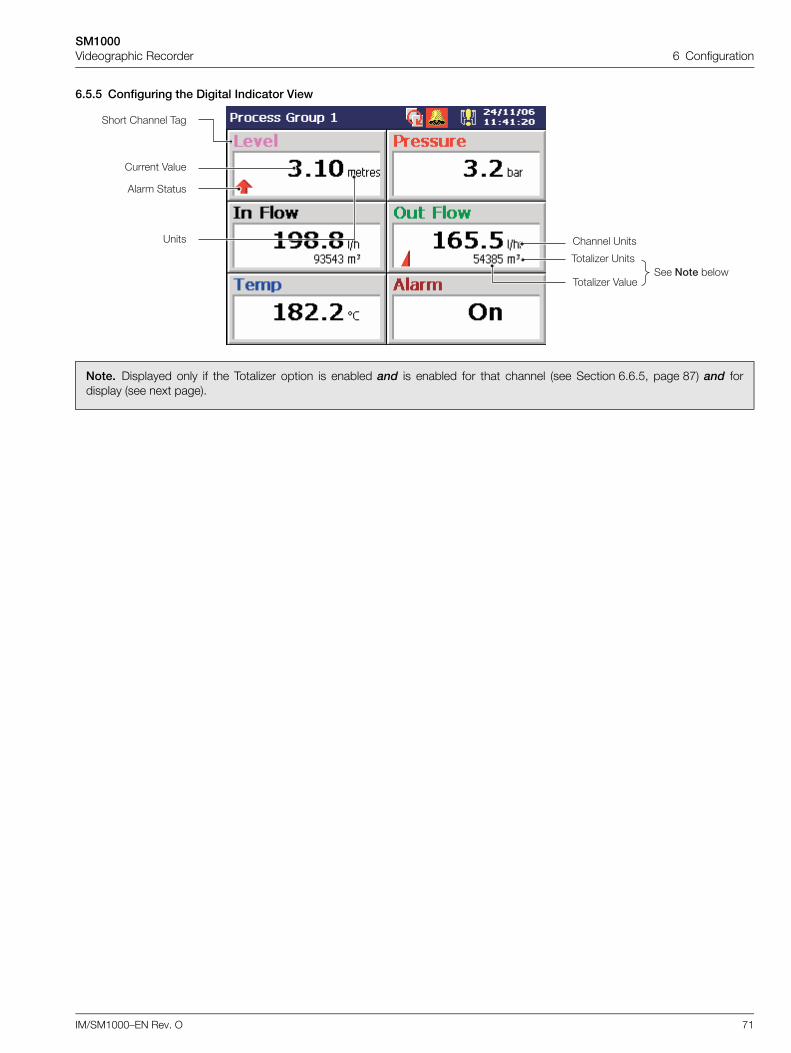
SM1000Videographic Recorder 6 Configuration
IM/SM1000–EN Rev. O 71
6.5.5 Configuring the Digital Indicator View
Note. Displayed only if the Totalizer option is enabled and is enabled for that channel (see Section 6.6.5, page 87) and fordisplay (see next page).
����� ?��
,����2�� 4����
,����2�� ?��
���� ����� ,��
����� 4����
'���� ����
?��
��� ��� *����
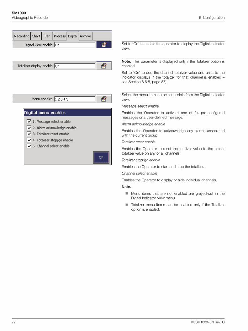
SM1000Videographic Recorder 6 Configuration
72 IM/SM1000–EN Rev. O
Set to 'On' to enable the operator to display the Digital Indicatorview.
Note. This parameter is displayed only if the Totalizer option isenabled.
Set to 'On' to add the channel totalizer value and units to theindicator displays (if the totalizer for that channel is enabled –see Section 6.6.5, page 87).
Select the menu items to be accessible from the Digital Indicatorview.
Message select enable
Enables the Operator to activate one of 24 pre-configuredmessages or a user-defined message.
Alarm acknowledge enable
Enables the Operator to acknowledge any alarms associatedwith the current group.
Totalizer reset enable
Enables the Operator to reset the totalizer value to the presettotalizer value on any or all channels.
Totalizer stop/go enable
Enables the Operator to start and stop the totalizer.
Channel select enable
Enables the Operator to display or hide individual channels.
Note.
Menu items that are not enabled are greyed-out in theDigital Indicator View menu.
Totalizer menu items can be enabled only if the Totalizeroption is enabled.
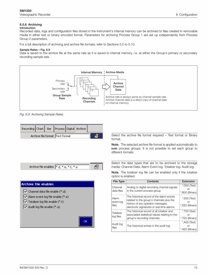
SM1000Videographic Recorder 6 Configuration
IM/SM1000–EN Rev. O 73
6.5.6 ArchivingIntroductionRecorded data, logs and configuration files stored in the instrument's internal memory can be archived to files created in removablemedia in either text or binary encoded format. Parameters for archiving Process Group 1 are set up independently from ProcessGroup 2 parameters.
For a full description of archiving and archive file formats, refer to Sections 5.5 to 5.10.
Sample Rates – Fig. 6.9Data is saved to the archive file at the same rate as it is saved to internal memory, i.e. at either the Group's primary or secondaryrecording sample rate.
Fig. 6.9 Archiving Sample Rates
Select the archive file format required – Text format or Binaryformat.
Note. The selected archive file format is applied automatically toboth process groups. It is not possible to set each group todifferent formats.
Select the data types that are to be archived to the storagemedia: Channel Data; Alarm Event log; Totalizer log; Audit log.
Note. The totalizer log file can be enabled only if the totalizeroption is enabled.
File Type Contents Extension
Channel data files
Analog or digital recording channel signals in the current process group
*.D00 (Text)or
*.B00 (Binary)
Alarm event log files
The historical record of the alarm events related to the group's channels plus the history of any operator messages, electronic signatures or real time alarms.
*.E00 (Text)or
*.EE0 (Binary)
Totalizer log files
The historical record of all totalizer and associated statistical values relating to the group's recording channels.
*.T00 (Text)or
*.TE0 (Binary)
Audit log files
The historical entries in the audit log. *.A00 (Text)
or*.AE0 (Binary)
�"��"!
�"#�"$
�"%�"&
���'��,'����
����
������� ,'�����
�������������
�����������
5���������
'���� � ��� �� ������ ���� �� ����� ������ ���"'���� � ����� ��� �� � ����� ���� �� ����� ���� ����� ������
���'��1����������1���3
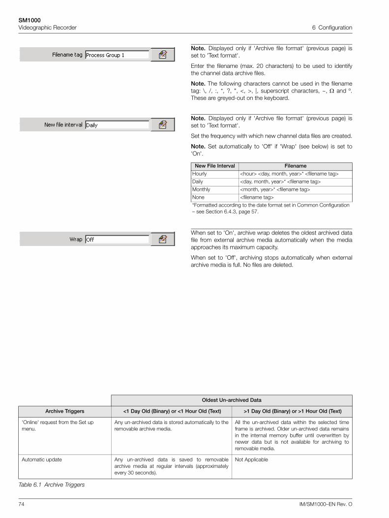
SM1000Videographic Recorder 6 Configuration
74 IM/SM1000–EN Rev. O
Note. Displayed only if 'Archive file format' (previous page) isset to 'Text format'.
Enter the filename (max. 20 characters) to be used to identifythe channel data archive files.
Note. The following characters cannot be used in the filenametag: \, /, :, *, ?, ", <, >, |, superscript characters, ~, and º.These are greyed-out on the keyboard.
Note. Displayed only if 'Archive file format' (previous page) isset to 'Text format'.
Set the frequency with which new channel data files are created.
Note. Set automatically to 'Off' if 'Wrap' (see below) is set to'On'.
New File Interval Filename
Hourly <hour> <day, month, year>* <filename tag>
Daily <day, month, year>* <filename tag>
Monthly <month, year>* <filename tag>
None <filename tag>
*Formatted according to the date format set in Common Configuration – see Section 6.4.3, page 57.
When set to 'On', archive wrap deletes the oldest archived datafile from external archive media automatically when the mediaapproaches its maximum capacity.
When set to 'Off', archiving stops automatically when externalarchive media is full. No files are deleted.
Oldest Un-archived Data
Archive Triggers <1 Day Old (Binary) or <1 Hour Old (Text) >1 Day Old (Binary) or >1 Hour Old (Text)
'Online' request from the Set up menu.
Any un-archived data is stored automatically to theremovable archive media.
All the un-archived data within the selected timeframe is archived. Older un-archived data remainsin the internal memory buffer until overwritten bynewer data but is not available for archiving toremovable media.
Automatic update Any un-archived data is saved to removablearchive media at regular intervals (approximatelyevery 30 seconds).
Not Applicable
Table 6.1 Archive Triggers
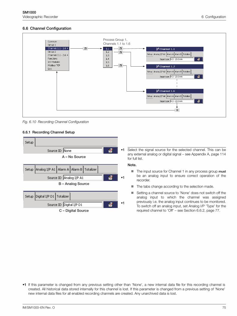
SM1000Videographic Recorder 6 Configuration
IM/SM1000–EN Rev. O 75
6.6 Channel Configuration
6.6.1 Recording Channel Setup
Fig. 6.10 Recording Channel Configuration
Select the signal source for the selected channel. This can beany external analog or digital signal – see Appendix A, page 114for full list.
Note.
The input source for Channel 1 in any process group mustbe an analog input to ensure correct operation of therecorder.
The tabs change according to the selection made.
Setting a channel source to 'None' does not switch off theanalog input to which the channel was assignedpreviously i.e. the analog input continues to be monitored.To switch off an analog input, set Analog I/P 'Type' for therequired channel to 'Off' – see Section 6.6.2, page 77.
•1 If this parameter is changed from any previous setting other than 'None', a new internal data file for this recording channel iscreated. All historical data stored internally for this channel is lost. If this parameter is changed from a previous setting of 'None'new internal data files for all enabled recording channels are created. Any unarchived data is lost.
5������ 6���� �-������ �"� � �"&
9�
(6����� �����
9�
,6�� ���������
9�
�6�������
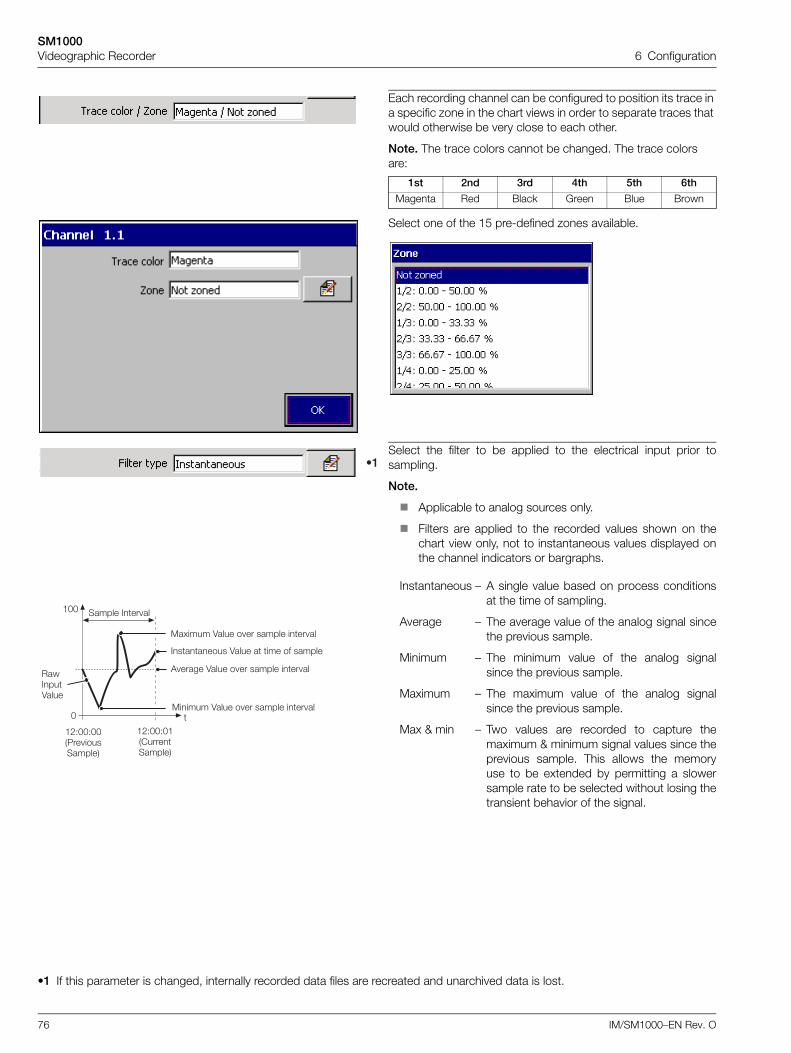
SM1000Videographic Recorder 6 Configuration
76 IM/SM1000–EN Rev. O
Each recording channel can be configured to position its trace in a specific zone in the chart views in order to separate traces that would otherwise be very close to each other.
Note. The trace colors cannot be changed. The trace colors are:
1st 2nd 3rd 4th 5th 6th
Magenta Red Black Green Blue Brown
Select one of the 15 pre-defined zones available.
Select the filter to be applied to the electrical input prior tosampling.
Note.
Applicable to analog sources only.
Filters are applied to the recorded values shown on thechart view only, not to instantaneous values displayed onthe channel indicators or bargraphs.
Instantaneous – A single value based on process conditionsat the time of sampling.
Average – The average value of the analog signal sincethe previous sample.
Minimum – The minimum value of the analog signalsince the previous sample.
Maximum – The maximum value of the analog signalsince the previous sample.
Max & min – Two values are recorded to capture themaximum & minimum signal values since theprevious sample. This allows the memoryuse to be extended by permitting a slowersample rate to be selected without losing thetransient behavior of the signal.
•1 If this parameter is changed, internally recorded data files are recreated and unarchived data is lost.
9�
������4����
�������� 4���� � ��� �� ������
������ ��� ��
������ 4���� � �� ������ ��� ��
' ����� 4���� � �� ������ ��� ��
��.���� 4���� � �� ������ ��� ��
�!DFFDFF�5�� �����������
�!DFFDF��������������
F
�FF
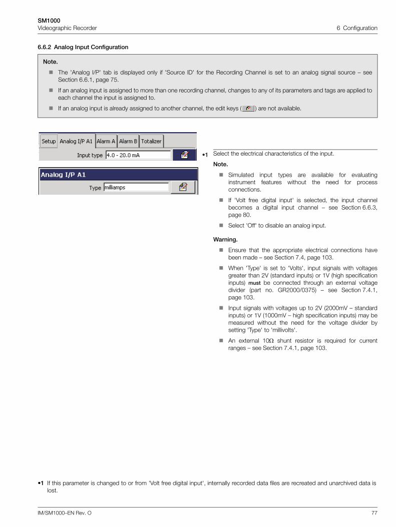
SM1000Videographic Recorder 6 Configuration
IM/SM1000–EN Rev. O 77
6.6.2 Analog Input Configuration
Note.
The 'Analog I/P' tab is displayed only if 'Source ID' for the Recording Channel is set to an analog signal source – seeSection 6.6.1, page 75.
If an analog input is assigned to more than one recording channel, changes to any of its parameters and tags are applied toeach channel the input is assigned to.
If an analog input is already assigned to another channel, the edit keys ( ) are not available.
Select the electrical characteristics of the input.
Note.
Simulated input types are available for evaluatinginstrument features without the need for processconnections.
If 'Volt free digital input' is selected, the input channelbecomes a digital input channel – see Section 6.6.3,page 80.
Select 'Off' to disable an analog input.
Warning.
Ensure that the appropriate electrical connections havebeen made – see Section 7.4, page 103.
When 'Type' is set to 'Volts', input signals with voltagesgreater than 2V (standard inputs) or 1V (high specificationinputs) must be connected through an external voltagedivider (part no. GR2000/0375) – see Section 7.4.1,page 103.
Input signals with voltages up to 2V (2000mV – standardinputs) or 1V (1000mV – high specification inputs) may bemeasured without the need for the voltage divider bysetting 'Type' to 'millivolts'.
An external 10 shunt resistor is required for currentranges – see Section 7.4.1, page 103.
•1 If this parameter is changed to or from 'Volt free digital input', internally recorded data files are recreated and unarchived data islost.
9�
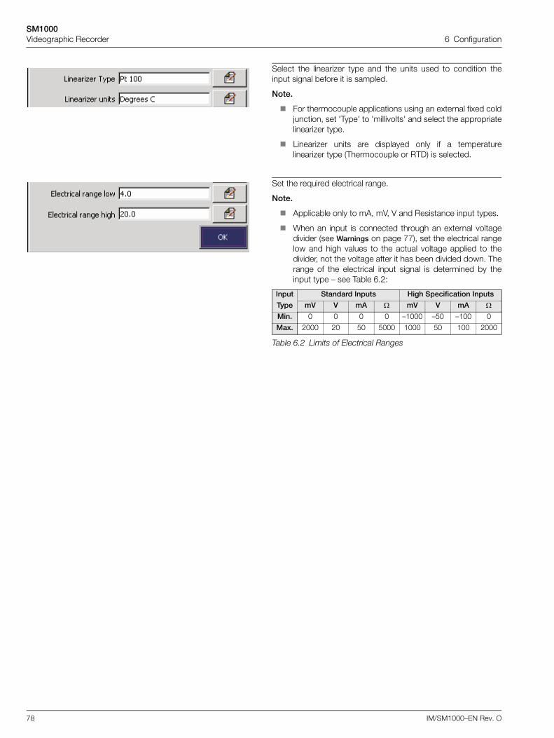
SM1000Videographic Recorder 6 Configuration
78 IM/SM1000–EN Rev. O
Select the linearizer type and the units used to condition theinput signal before it is sampled.
Note.
For thermocouple applications using an external fixed coldjunction, set 'Type' to 'millivolts' and select the appropriatelinearizer type.
Linearizer units are displayed only if a temperaturelinearizer type (Thermocouple or RTD) is selected.
Set the required electrical range.
Note.
Applicable only to mA, mV, V and Resistance input types.
When an input is connected through an external voltagedivider (see Warnings on page 77), set the electrical rangelow and high values to the actual voltage applied to thedivider, not the voltage after it has been divided down. Therange of the electrical input signal is determined by theinput type – see Table 6.2:
Input Standard Inputs High Specification Inputs
Type mV V mA mV V mA Min. 0 0 0 0 –1000 –50 –100 0
Max. 2000 20 50 5000 1000 50 100 2000
Table 6.2 Limits of Electrical Ranges
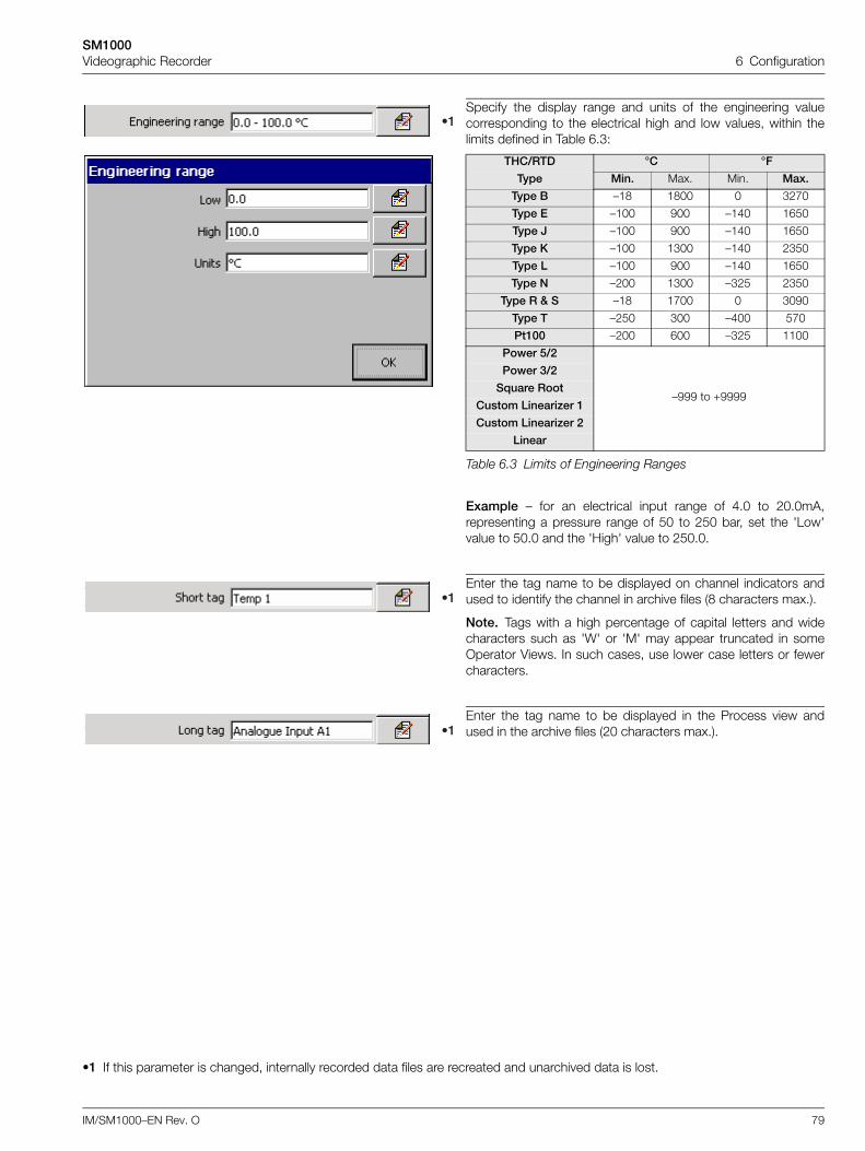
SM1000Videographic Recorder 6 Configuration
IM/SM1000–EN Rev. O 79
Specify the display range and units of the engineering valuecorresponding to the electrical high and low values, within thelimits defined in Table 6.3:
9�
THC/RTD °C °F
Type Min. Max. Min. Max.
Type B –18 1800 0 3270
Type E –100 900 –140 1650
Type J –100 900 –140 1650
Type K –100 1300 –140 2350
Type L –100 900 –140 1650
Type N –200 1300 –325 2350
Type R & S –18 1700 0 3090
Type T –250 300 –400 570
Pt100 –200 600 –325 1100
Power 5/2
–999 to +9999
Power 3/2
Square Root
Custom Linearizer 1
Custom Linearizer 2
Linear
Table 6.3 Limits of Engineering Ranges
Example – for an electrical input range of 4.0 to 20.0mA,representing a pressure range of 50 to 250 bar, set the 'Low'value to 50.0 and the 'High' value to 250.0.
Enter the tag name to be displayed on channel indicators andused to identify the channel in archive files (8 characters max.).
Note. Tags with a high percentage of capital letters and widecharacters such as 'W' or 'M' may appear truncated in someOperator Views. In such cases, use lower case letters or fewercharacters.
Enter the tag name to be displayed in the Process view andused in the archive files (20 characters max.).
•1 If this parameter is changed, internally recorded data files are recreated and unarchived data is lost.
9�
9�
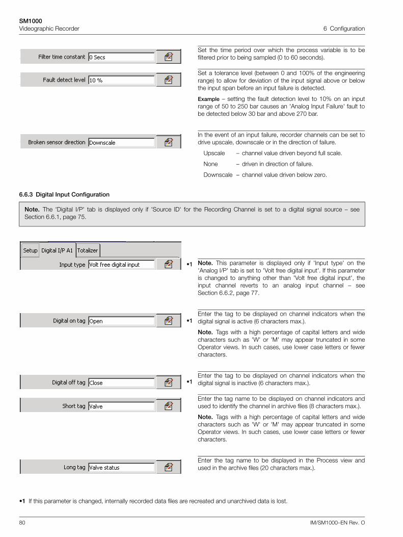
SM1000Videographic Recorder 6 Configuration
80 IM/SM1000–EN Rev. O
6.6.3 Digital Input Configuration
Set the time period over which the process variable is to befiltered prior to being sampled (0 to 60 seconds).
Set a tolerance level (between 0 and 100% of the engineeringrange) to allow for deviation of the input signal above or belowthe input span before an input failure is detected.
Example – setting the fault detection level to 10% on an inputrange of 50 to 250 bar causes an 'Analog Input Failure' fault tobe detected below 30 bar and above 270 bar.
In the event of an input failure, recorder channels can be set todrive upscale, downscale or in the direction of failure.
Upscale – channel value driven beyond full scale.
None – driven in direction of failure.
Downscale – channel value driven below zero.
Note. The 'Digital I/P' tab is displayed only if 'Source ID' for the Recording Channel is set to a digital signal source – seeSection 6.6.1, page 75.
Note. This parameter is displayed only if 'Input type' on the'Analog I/P' tab is set to 'Volt free digital input'. If this parameteris changed to anything other than 'Volt free digital input', theinput channel reverts to an analog input channel – seeSection 6.6.2, page 77.
Enter the tag to be displayed on channel indicators when thedigital signal is active (6 characters max.).
Note. Tags with a high percentage of capital letters and widecharacters such as 'W' or 'M' may appear truncated in someOperator views. In such cases, use lower case letters or fewercharacters.
Enter the tag to be displayed on channel indicators when thedigital signal is inactive (6 characters max.).
Enter the tag name to be displayed on channel indicators andused to identify the channel in archive files (8 characters max.).
Note. Tags with a high percentage of capital letters and widecharacters such as 'W' or 'M' may appear truncated in someOperator views. In such cases, use lower case letters or fewercharacters.
Enter the tag name to be displayed in the Process view andused in the archive files (20 characters max.).
•1 If this parameter is changed, internally recorded data files are recreated and unarchived data is lost.
9�
9�
9�
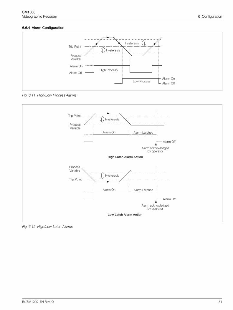
SM1000Videographic Recorder 6 Configuration
IM/SM1000–EN Rev. O 81
6.6.4 Alarm Configuration
Fig. 6.11 High/Low Process Alarms
Fig. 6.12 High/Low Latch Alarms
,��� 5��
'���� >
'���� >��
'���� >
'���� >��
;��� 5������
1�� 5������
;��������
;��������
5������4����*��
,��� 5��
'���� >
'���� >��
'���� 1�����
'���� ��<��������*� �������
;��������
5������4����*��
,��� 5��
'���� >
'���� >��
'���� 1�����
'���� ��<��������*� �������
;��������
5������4����*��
7� '����'�����������
��*����'�����������
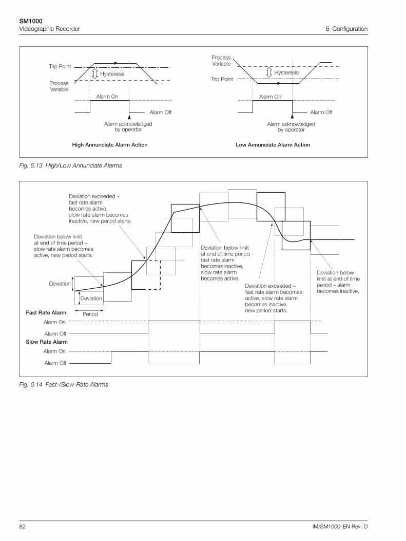
SM1000Videographic Recorder 6 Configuration
82 IM/SM1000–EN Rev. O
Fig. 6.13 High/Low Annunciate Alarms
Fig. 6.14 Fast-/Slow-Rate Alarms
7� '�������������������� ��*��������������������
'���� >
'���� ��<��������*� �������
;��������
5������4����*��
'���� >��
,��� 5��
,��� 5��
'���� >��
;��������
5������4����*��
'���� >
'���� ��<��������*� �������
)� ���� �.������ :��� ��� �����*������ ��� �-���� ��� ����� *���������� �- �� ������ ����"
)� ���� *���� ����� �� �� ��� ������ :��� ��� �����*������ ���� �-���� ��� �����*������ ��� �"
)� ���� *�������� � �� �� ��������� : �����*������ ���� �"
'���� >
'���� >��
8����������� 5�����
)� ����
)� ���� )� ���� �.������ :��� ��� ����� *��������� �- ���� ��� �����*������ ���� �-�� ������ ����"
)� ���� *���� ����� �� �� ��� ������ :���� ��� ����� *��������� �- �� ������ ����"
'���� >
'���� >��
���*��������
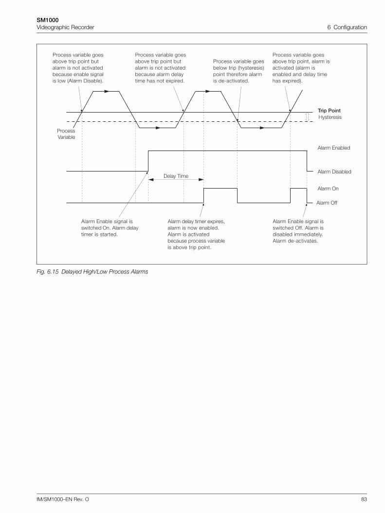
SM1000Videographic Recorder 6 Configuration
IM/SM1000–EN Rev. O 83
Fig. 6.15 Delayed High/Low Process Alarms
;��������
'���� >
'���� )���*���
'���� 0�*���
#��������
'���� >��
)���� ,���
5������4����*��
5������ ����*�� �����*� � ��� ��� *������ �� � ��� ���*������ ��*�� ������� ��� �'���� )���*���"
5������ ����*�� ����*���� ��� �������������� �������� ������� ��8��� ���"
'���� 0�*�� ����� ��������� >" '���� ��������� �� �����"
5������ ����*�� �����*� � ��� ��� *������ �� � ��� ���*������ ����� �������� ��� � �.�����"
'���� ����� ���� �.�����-����� �� �� ��*���"'���� �� ��� ���*������ ������� ����*���� �*� � ��� ���"
5������ ����*�� �����*� � ��� ���- ����� ����� ��� ������ ����*��� �� ����� ������ �.������"
'���� 0�*�� ����� ��������� >��" '���� ������*��� ����������"'���� ��8��� ���"
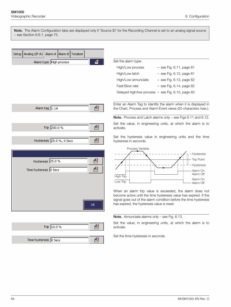
SM1000Videographic Recorder 6 Configuration
84 IM/SM1000–EN Rev. O
Note. The Alarm Configuration tabs are displayed only if 'Source ID' for the Recording Channel is set to an analog signal source– see Section 6.6.1, page 75.
Set the alarm type:
High/Low process – see Fig. 6.11, page 81
High/Low latch – see Fig. 6.12, page 81
High/Low annunciate – see Fig. 6.13, page 82
Fast/Slow rate – see Fig. 6.14, page 82
Delayed high/low process – see Fig. 6.15, page 83
Enter an Alarm Tag to identify the alarm when it is displayed inthe Chart, Process and Alarm Event views (20 characters max.).
Note. Process and Latch alarms only – see Figs 6.11 and 6.12.
Set the value, in engineering units, at which the alarm is toactivate.
Set the hysteresis value in engineering units and the timehysteresis in seconds.
When an alarm trip value is exceeded, the alarm does notbecome active until the time hysteresis value has expired. If thesignal goes out of the alarm condition before the time hysteresishas expired, the hysteresis value is reset.
Note. Annunciate alarms only – see Fig. 6.13.
Set the value, in engineering units, at which the alarm is toactivate.
Set the time hysteresis in seconds.
;��� ,���
1�� ,���
5������ 4����*��
;��������
;��������
,��� 5��
'���� >'���� >��
'���� >'���� >��
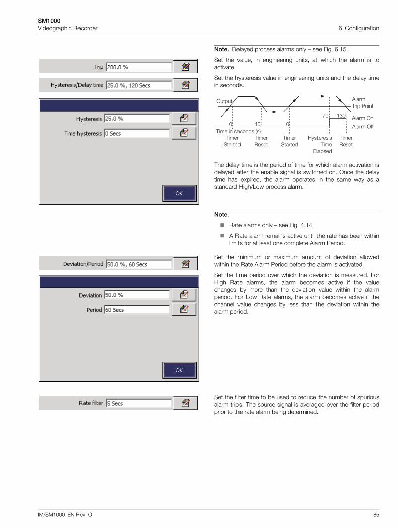
SM1000Videographic Recorder 6 Configuration
IM/SM1000–EN Rev. O 85
Note. Delayed process alarms only – see Fig. 6.15.
Set the value, in engineering units, at which the alarm is toactivate.
Set the hysteresis value in engineering units and the delay timein seconds.
The delay time is the period of time for which alarm activation isdelayed after the enable signal is switched on. Once the delaytime has expired, the alarm operates in the same way as astandard High/Low process alarm.
Note.
Rate alarms only – see Fig. 4.14.
A Rate alarm remains active until the rate has been withinlimits for at least one complete Alarm Period.
Set the minimum or maximum amount of deviation allowedwithin the Rate Alarm Period before the alarm is activated.
Set the time period over which the deviation is measured. ForHigh Rate alarms, the alarm becomes active if the valuechanges by more than the deviation value within the alarmperiod. For Low Rate alarms, the alarm becomes active if thechannel value changes by less than the deviation within thealarm period.
Set the filter time to be used to reduce the number of spuriousalarm trips. The source signal is averaged over the filter periodprior to the rate alarm being determined.
>��� '����,��� 5��
'���� >
'���� >��,��� � ������ ���
,���������
,��������
,���������
;��������,���
0������
,��������
$F FF
BF �#F
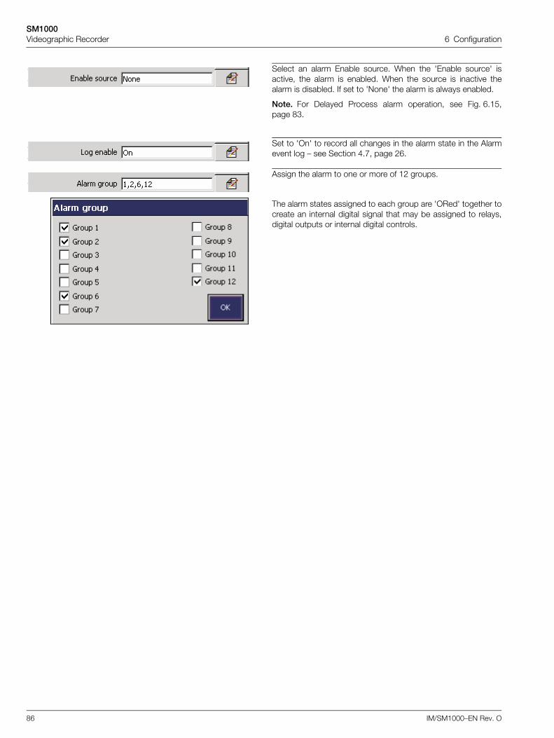
SM1000Videographic Recorder 6 Configuration
86 IM/SM1000–EN Rev. O
Select an alarm Enable source. When the 'Enable source' isactive, the alarm is enabled. When the source is inactive thealarm is disabled. If set to 'None' the alarm is always enabled.
Note. For Delayed Process alarm operation, see Fig. 6.15,page 83.
Set to 'On' to record all changes in the alarm state in the Alarmevent log – see Section 4.7, page 26.
Assign the alarm to one or more of 12 groups.
The alarm states assigned to each group are 'ORed' together tocreate an internal digital signal that may be assigned to relays,digital outputs or internal digital controls.
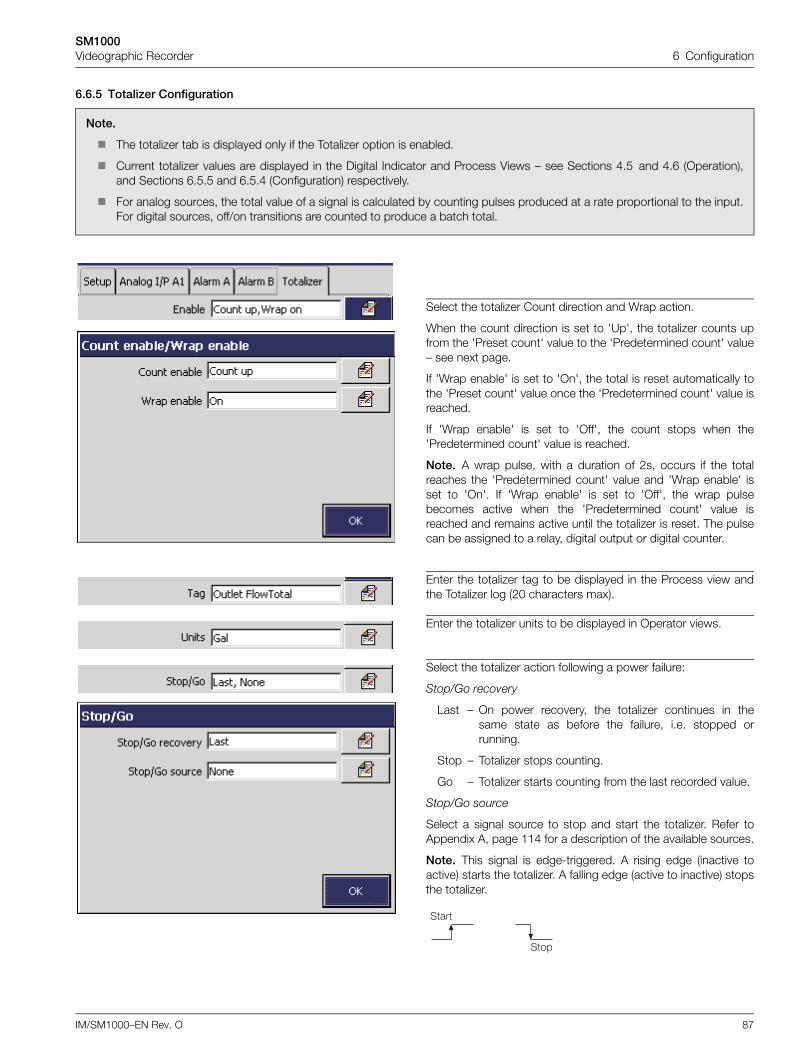
SM1000Videographic Recorder 6 Configuration
IM/SM1000–EN Rev. O 87
6.6.5 Totalizer Configuration
Note.
The totalizer tab is displayed only if the Totalizer option is enabled.
Current totalizer values are displayed in the Digital Indicator and Process Views – see Sections 4.5 and 4.6 (Operation),and Sections 6.5.5 and 6.5.4 (Configuration) respectively.
For analog sources, the total value of a signal is calculated by counting pulses produced at a rate proportional to the input.For digital sources, off/on transitions are counted to produce a batch total.
Select the totalizer Count direction and Wrap action.
When the count direction is set to 'Up', the totalizer counts upfrom the 'Preset count' value to the 'Predetermined count' value– see next page.
If 'Wrap enable' is set to 'On', the total is reset automatically tothe 'Preset count' value once the 'Predetermined count' value isreached.
If 'Wrap enable' is set to 'Off', the count stops when the'Predetermined count' value is reached.
Note. A wrap pulse, with a duration of 2s, occurs if the totalreaches the 'Predetermined count' value and 'Wrap enable' isset to 'On'. If 'Wrap enable' is set to 'Off', the wrap pulsebecomes active when the 'Predetermined count' value isreached and remains active until the totalizer is reset. The pulsecan be assigned to a relay, digital output or digital counter.
Enter the totalizer tag to be displayed in the Process view andthe Totalizer log (20 characters max).
Enter the totalizer units to be displayed in Operator views.
Select the totalizer action following a power failure:
Stop/Go recovery
Last – On power recovery, the totalizer continues in thesame state as before the failure, i.e. stopped orrunning.
Stop – Totalizer stops counting.
Go – Totalizer starts counting from the last recorded value.
Stop/Go source
Select a signal source to stop and start the totalizer. Refer toAppendix A, page 114 for a description of the available sources.
Note. This signal is edge-triggered. A rising edge (inactive toactive) starts the totalizer. A falling edge (active to inactive) stopsthe totalizer.
���
���
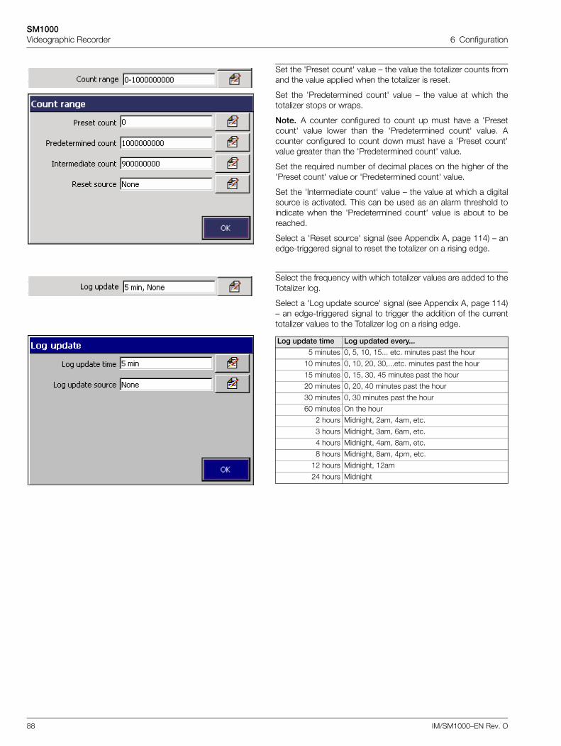
SM1000Videographic Recorder 6 Configuration
88 IM/SM1000–EN Rev. O
Set the 'Preset count' value – the value the totalizer counts fromand the value applied when the totalizer is reset.
Set the 'Predetermined count' value – the value at which thetotalizer stops or wraps.
Note. A counter configured to count up must have a 'Presetcount' value lower than the 'Predetermined count' value. Acounter configured to count down must have a 'Preset count'value greater than the 'Predetermined count' value.
Set the required number of decimal places on the higher of the'Preset count' value or 'Predetermined count' value.
Set the 'Intermediate count' value – the value at which a digitalsource is activated. This can be used as an alarm threshold toindicate when the 'Predetermined count' value is about to bereached.
Select a 'Reset source' signal (see Appendix A, page 114) – anedge-triggered signal to reset the totalizer on a rising edge.
Select the frequency with which totalizer values are added to theTotalizer log.
Select a 'Log update source' signal (see Appendix A, page 114)– an edge-triggered signal to trigger the addition of the currenttotalizer values to the Totalizer log on a rising edge.
Log update time Log updated every...
5 minutes 0, 5, 10, 15... etc. minutes past the hour
10 minutes 0, 10, 20, 30,...etc. minutes past the hour
15 minutes 0, 15, 30, 45 minutes past the hour
20 minutes 0, 20, 40 minutes past the hour
30 minutes 0, 30 minutes past the hour
60 minutes On the hour
2 hours Midnight, 2am, 4am, etc.
3 hours Midnight, 3am, 6am, etc.
4 hours Midnight, 4am, 8am, etc.
8 hours Midnight, 8am, 4pm, etc.
12 hours Midnight, 12am
24 hours Midnight
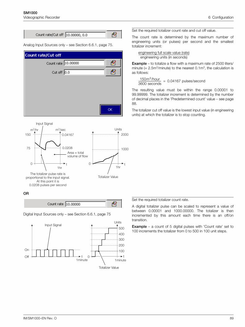
SM1000Videographic Recorder 6 Configuration
IM/SM1000–EN Rev. O 89
Analog Input Sources only – see Section 6.6.1, page 75.
Set the required totalizer count rate and cut off value.
The count rate is determined by the maximum number ofengineering units (or pulses) per second and the smallesttotalizer increment:
Example – to totalize a flow with a maximum rate of 2500 liters/minute (= 2.5m3/minute) to the nearest 0.1m3, the calculation isas follows:
The resulting value must be within the range 0.00001 to99.99999. The totalizer increment is determined by the numberof decimal places in the 'Predetermined count' value – see page88.
The totalizer cut off value is the lowest input value (in engineeringunits) at which the totalizer is to stop counting.
OR
Digital Input Sources only – see Section 6.6.1, page 75
Set the required totalizer count rate.
A digital totalizer pulse can be scaled to represent a value ofbetween 0.00001 and 1000.00000. The totalizer is thenincremented by this amount each time there is an off/ontransition.
Example – a count of 5 digital pulses with 'Count rate' set to100 increments the totalizer from 0 to 500 in 100 unit steps.
engineering full scale value (rate)engineering units (in seconds)
--------------------------------------------------------------------------
150m3/hour3600 seconds--------------------------------- 0.04167 pulses/second=
,�� ����2�� ����� ��� ������������ � �� ��� �����"
' ��� ��� � ��F"F!FO ������ ��� �����
F
�%F
'��� @ ��� ����� �� ����
�#/�� �#/���
F"F$�&B
F"F!FOB%
���
��� �����
F
!FFF
?��
�FFF
���
,����2�� 4����
>�� �����
��� �����
F
%FF
?��
�����
,����2�� 4����
$FF
#FF
!FF
�FF>
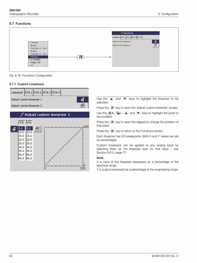
SM1000Videographic Recorder 6 Configuration
90 IM/SM1000–EN Rev. O
6.7 Functions
6.7.1 Custom Linearizers
Fig. 6.16 Functions Configuration
Use the and keys to highlight the linearizer to beadjusted.
Press the key to open the 'Adjust custom linearizer' screen.
Use the , , and keys to highlight the point tobe modified.
Press the key to open the digipad to change the position ofthat point.
Press the key to return to the Functions screen.
Each linearizer has 20 breakpoints. Both X and Y values are setas percentages.
Custom linearizers can be applied to any analog input byselecting them as the linearizer type for that input – seeSection 6.6.2, page 77.
Note.X is input to the linearizer expressed as a percentage of theelectrical range.Y is output expressed as a percentage of the engineering range.
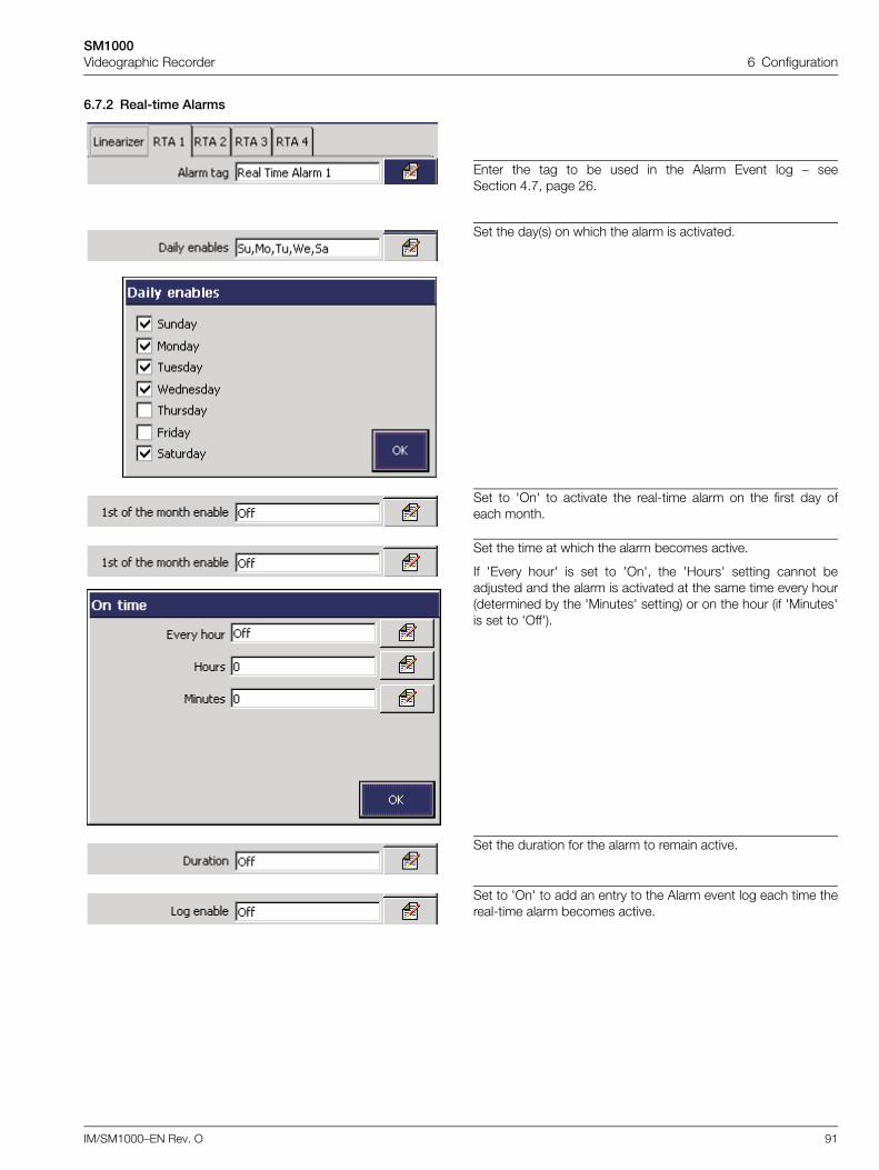
SM1000Videographic Recorder 6 Configuration
IM/SM1000–EN Rev. O 91
6.7.2 Real-time Alarms
Enter the tag to be used in the Alarm Event log – seeSection 4.7, page 26.
Set the day(s) on which the alarm is activated.
Set to 'On' to activate the real-time alarm on the first day ofeach month.
Set the time at which the alarm becomes active.
If 'Every hour' is set to 'On', the 'Hours' setting cannot beadjusted and the alarm is activated at the same time every hour(determined by the 'Minutes' setting) or on the hour (if 'Minutes'is set to 'Off').
Set the duration for the alarm to remain active.
Set to 'On' to add an entry to the Alarm event log each time thereal-time alarm becomes active.
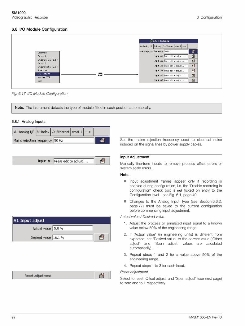
SM1000Videographic Recorder 6 Configuration
92 IM/SM1000–EN Rev. O
6.8 I/O Module Configuration
6.8.1 Analog Inputs
Fig. 6.17 I/O Module Configuration
Note. The instrument detects the type of module fitted in each position automatically.
Set the mains rejection frequency used to electrical noiseinduced on the signal lines by power supply cables.
Input Adjustment
Manually fine-tune inputs to remove process offset errors orsystem scale errors.
Note.
Input adjustment frames appear only if recording isenabled during configuration, i.e. the 'Disable recording inconfiguration' check box is not ticked on entry to theConfiguration level – see Fig. 6.1, page 49.
Changes to the Analog Input Type (see Section 6.6.2,page 77) must be saved to the current configurationbefore commencing input adjustment.
Actual value / Desired value
1. Adjust the process or simulated input signal to a knownvalue below 50% of the engineering range.
2. If 'Actual value' (in engineering units) is different fromexpected, set 'Desired value' to the correct value ('Offsetadjust' and 'Span adjust' values are calculatedautomatically).
3. Repeat steps 1 and 2 for a value above 50% of theengineering range.
4. Repeat steps 1 to 3 for each input.
Reset adjustment
Select to reset 'Offset adjust' and 'Span adjust' (see next page)to zero and to 1 respectively.
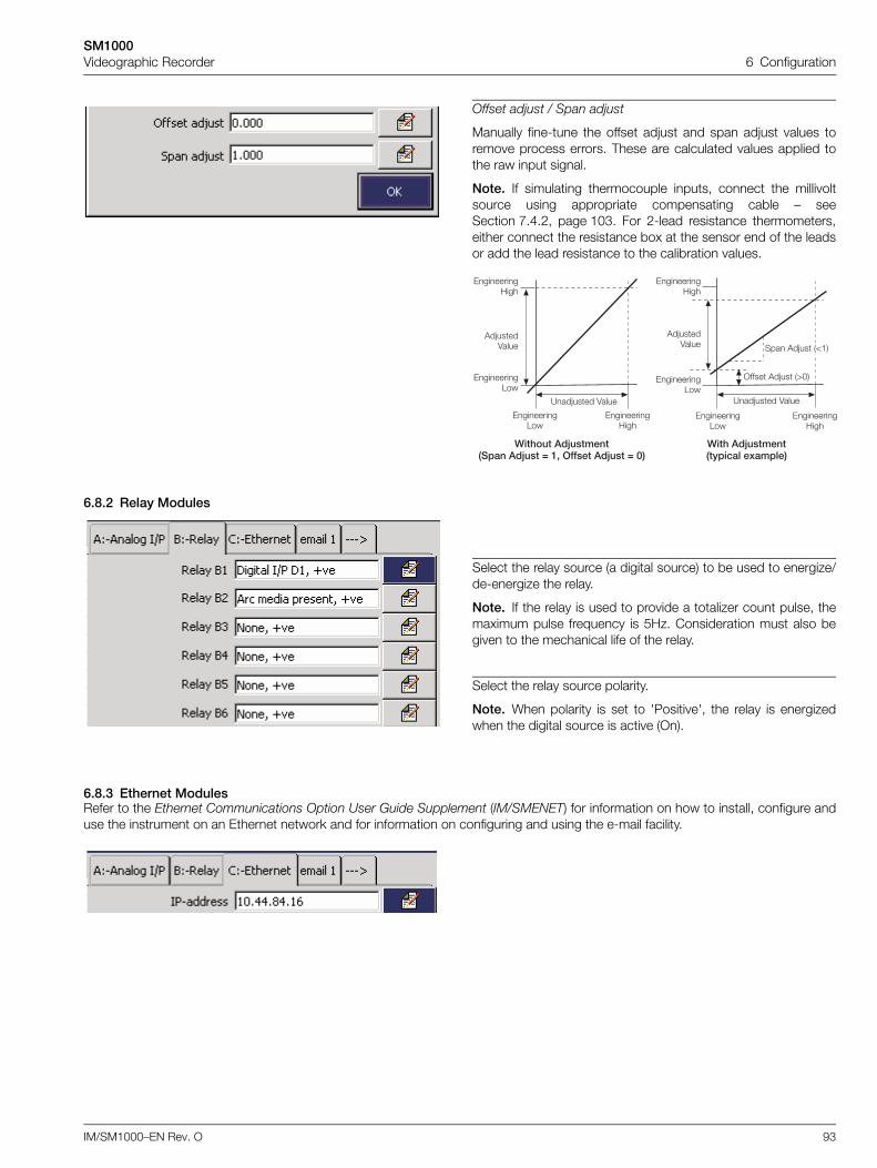
SM1000Videographic Recorder 6 Configuration
IM/SM1000–EN Rev. O 93
6.8.2 Relay Modules
6.8.3 Ethernet ModulesRefer to the Ethernet Communications Option User Guide Supplement (IM/SMENET) for information on how to install, configure anduse the instrument on an Ethernet network and for information on configuring and using the e-mail facility.
Offset adjust / Span adjust
Manually fine-tune the offset adjust and span adjust values toremove process errors. These are calculated values applied tothe raw input signal.
Note. If simulating thermocouple inputs, connect the millivoltsource using appropriate compensating cable – seeSection 7.4.2, page 103. For 2-lead resistance thermometers,either connect the resistance box at the sensor end of the leadsor add the lead resistance to the calibration values.
>��'�����?������ ������?���@�AB00����?���@C"
0�������1��
0�������;���
?��G���� 4����
0�������1��
0�������;���
'�G����4����
>��'��?������ �3�����D����"
'�G����4����
0�������1��
0�������;���
0�������1��
0�������;���
?��G���� 4����
>���� '�G�� �CF�
��� '�G�� �E��
Select the relay source (a digital source) to be used to energize/de-energize the relay.
Note. If the relay is used to provide a totalizer count pulse, themaximum pulse frequency is 5Hz. Consideration must also begiven to the mechanical life of the relay.
Select the relay source polarity.
Note. When polarity is set to 'Positive', the relay is energizedwhen the digital source is active (On).
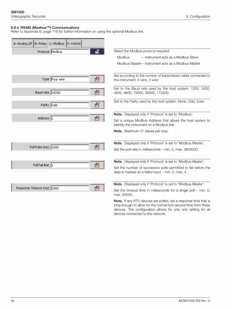
SM1000Videographic Recorder 6 Configuration
94 IM/SM1000–EN Rev. O
6.8.4 RS485 (Modbus™) CommunicationsRefer to Appendix B, page 116 for further information on using the optional Modbus link.
Select the Modbus protocol required.
Modbus – instrument acts as a Modbus Slave
Modbus Master – instrument acts as a Modbus Master
Set according to the number of transmission wires connected tothe instrument: 4-wire, 2-wire.
Set to the Baud rate used by the host system: 1200, 2400,4800, 9600, 19200, 38400, 115200.
Set to the Parity used by the host system: None, Odd, Even.
Note. Displayed only if 'Protocol' is set to 'Modbus'.
Set a unique Modbus Address that allows the host system toidentify the instrument on a Modbus link.
Note. Maximum 31 slaves per loop.
Note. Displayed only if 'Protocol' is set to 'Modbus Master'.
Set the poll rate in milliseconds – min. 0, max. 3600000.
Note. Displayed only if 'Protocol' is set to 'Modbus Master'.
Set the number of successive polls permitted to fail before thedata is marked as a failed input – min. 0, max. 4.
Note. Displayed only if 'Protocol' is set to 'Modbus Master'.
Set the timeout time in milliseconds for a single poll – min. 0,max. 60000.
Note. If any RTU devices are polled, set a response time that islong enough to allow for the normal turn around time from thesedevices. The configuration allows for only one setting for alldevices connected to the network.
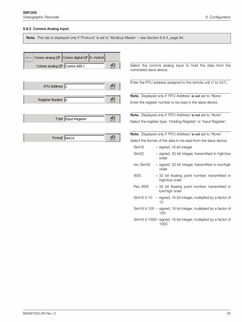
SM1000Videographic Recorder 6 Configuration
IM/SM1000–EN Rev. O 95
6.8.5 Comms Analog Input
Note. This tab is displayed only if 'Protocol' is set to 'Modbus Master' – see Section 6.8.4, page 94.
Select the comms analog input to hold the data from thenominated slave device.
Enter the RTU address assigned to the remote unit (1 to 247).
Note. Displayed only if 'RTU Address' is not set to 'None'.
Enter the register number to be read in the slave device.
Note. Displayed only if 'RTU Address' is not set to 'None'.
Select the register type, 'Holding Register' or 'Input Register'.
Note. Displayed only if 'RTU Address' is not set to 'None'.
Select the format of the data to be read from the slave device:
Sint16 – signed, 16 bit integer
Sint32 – signed, 32 bit integer, transmitted in high/loworder
rev. Sint32 – signed, 32 bit integer, transmitted in low/highorder
IEEE – 32 bit floating point number, transmitted inhigh/low order
Rev. IEEE – 32 bit floating point number, transmitted inlow/high order
Sint16 X 10 – signed, 16 bit integer, multiplied by a factor of10
Sint16 X 100 – signed, 16 bit integer, multiplied by a factor of100
Sint16 X 1000– signed, 16 bit integer, multiplied by a factor of1000
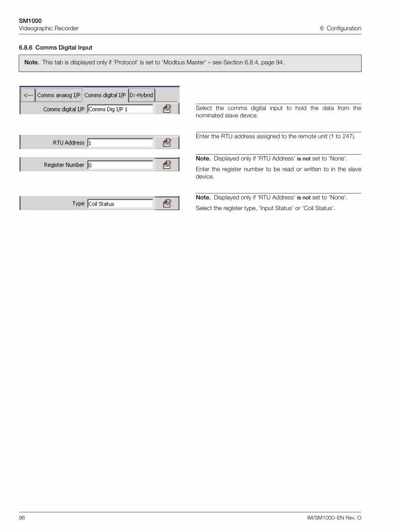
SM1000Videographic Recorder 6 Configuration
96 IM/SM1000–EN Rev. O
6.8.6 Comms Digital Input
Note. This tab is displayed only if 'Protocol' is set to 'Modbus Master' – see Section 6.8.4, page 94.
Select the comms digital input to hold the data from thenominated slave device.
Enter the RTU address assigned to the remote unit (1 to 247).
Note. Displayed only if 'RTU Address' is not set to 'None'.
Enter the register number to be read or written to in the slavedevice.
Note. Displayed only if 'RTU Address' is not set to 'None'.
Select the register type, 'Input Status' or 'Coil Status'.
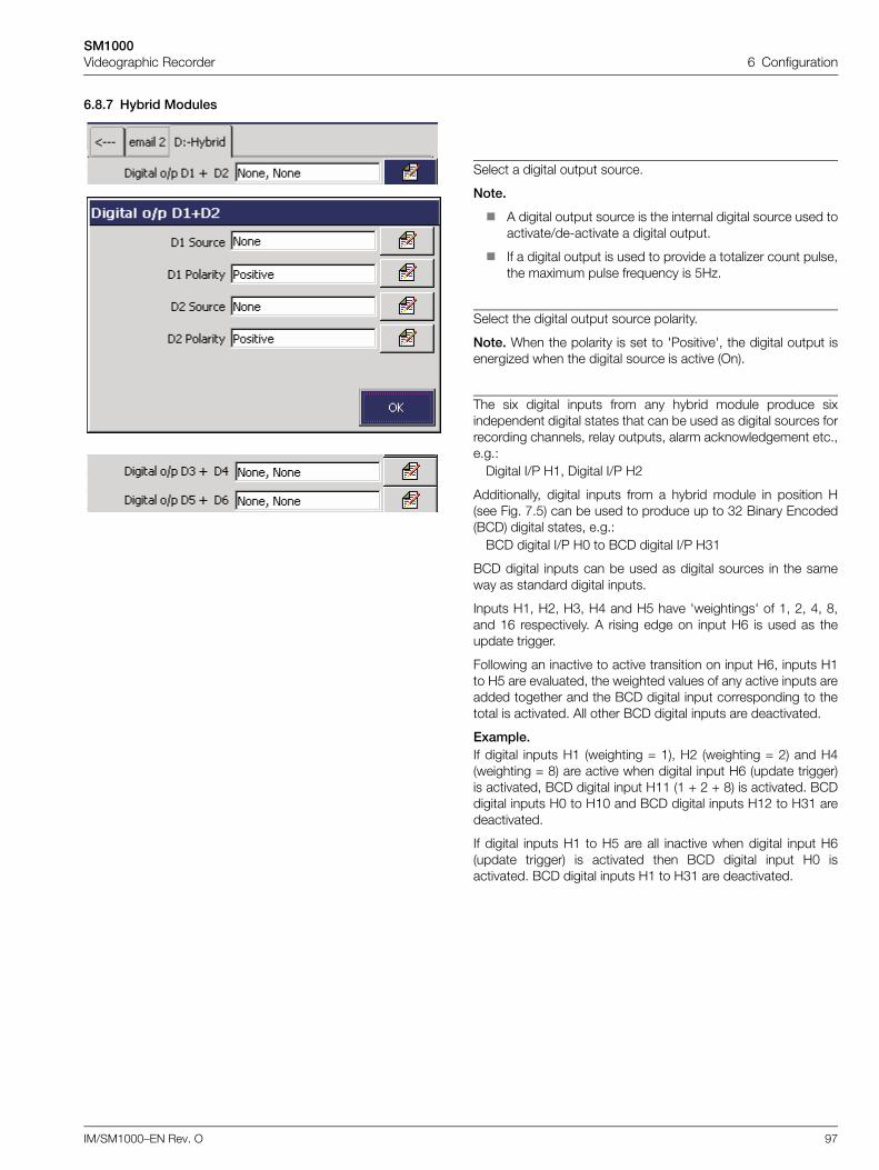
SM1000Videographic Recorder 6 Configuration
IM/SM1000–EN Rev. O 97
6.8.7 Hybrid Modules
Select a digital output source.
Note.
A digital output source is the internal digital source used toactivate/de-activate a digital output.
If a digital output is used to provide a totalizer count pulse,the maximum pulse frequency is 5Hz.
Select the digital output source polarity.
Note. When the polarity is set to 'Positive', the digital output isenergized when the digital source is active (On).
The six digital inputs from any hybrid module produce sixindependent digital states that can be used as digital sources forrecording channels, relay outputs, alarm acknowledgement etc.,e.g.:
Digital I/P H1, Digital I/P H2
Additionally, digital inputs from a hybrid module in position H(see Fig. 7.5) can be used to produce up to 32 Binary Encoded(BCD) digital states, e.g.:
BCD digital I/P H0 to BCD digital I/P H31
BCD digital inputs can be used as digital sources in the sameway as standard digital inputs.
Inputs H1, H2, H3, H4 and H5 have 'weightings' of 1, 2, 4, 8,and 16 respectively. A rising edge on input H6 is used as theupdate trigger.
Following an inactive to active transition on input H6, inputs H1to H5 are evaluated, the weighted values of any active inputs areadded together and the BCD digital input corresponding to thetotal is activated. All other BCD digital inputs are deactivated.
Example.If digital inputs H1 (weighting = 1), H2 (weighting = 2) and H4(weighting = 8) are active when digital input H6 (update trigger)is activated, BCD digital input H11 (1 + 2 + 8) is activated. BCDdigital inputs H0 to H10 and BCD digital inputs H12 to H31 aredeactivated.
If digital inputs H1 to H5 are all inactive when digital input H6(update trigger) is activated then BCD digital input H0 isactivated. BCD digital inputs H1 to H31 are deactivated.
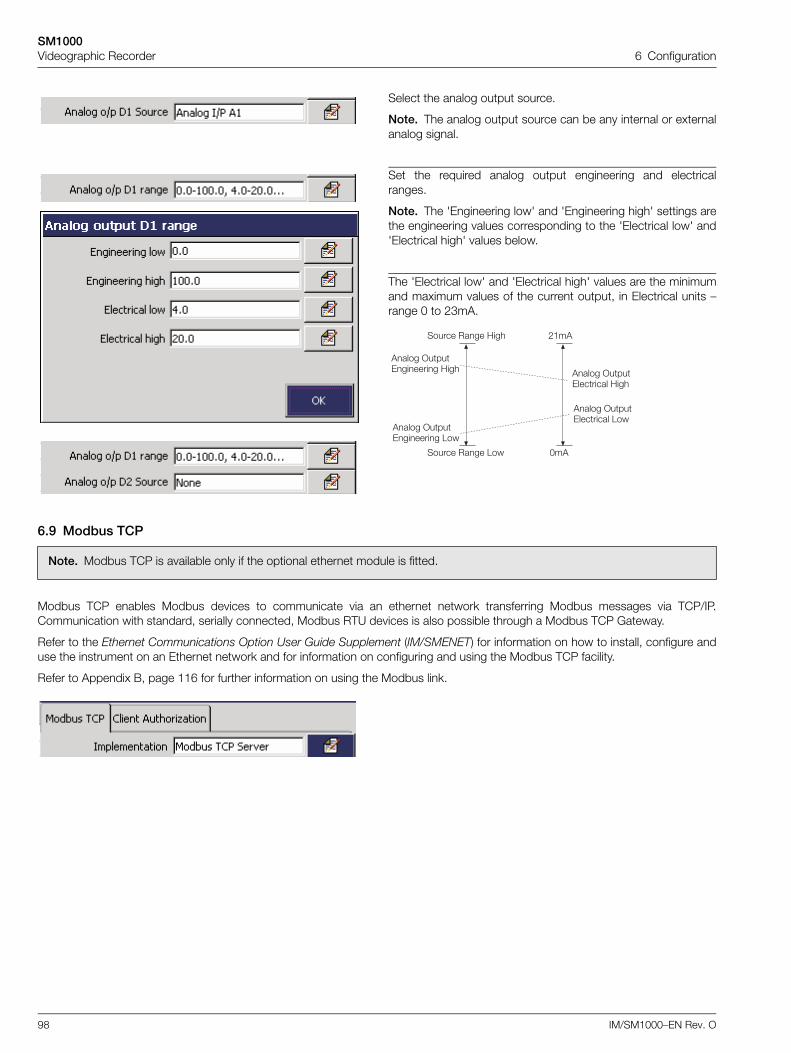
SM1000Videographic Recorder 6 Configuration
98 IM/SM1000–EN Rev. O
6.9 Modbus TCP
Modbus TCP enables Modbus devices to communicate via an ethernet network transferring Modbus messages via TCP/IP.Communication with standard, serially connected, Modbus RTU devices is also possible through a Modbus TCP Gateway.
Refer to the Ethernet Communications Option User Guide Supplement (IM/SMENET) for information on how to install, configure anduse the instrument on an Ethernet network and for information on configuring and using the Modbus TCP facility.
Refer to Appendix B, page 116 for further information on using the Modbus link.
Select the analog output source.
Note. The analog output source can be any internal or externalanalog signal.
Set the required analog output engineering and electricalranges.
Note. The 'Engineering low' and 'Engineering high' settings arethe engineering values corresponding to the 'Electrical low' and'Electrical high' values below.
The 'Electrical low' and 'Electrical high' values are the minimumand maximum values of the current output, in Electrical units –range 0 to 23mA.
Note. Modbus TCP is available only if the optional ethernet module is fitted.
'���� >���0������� ;���
!��'
F�'
'���� >���0������� 1��
'���� >���0�������� ;���
'���� >���0�������� 1��
������ ���� ;���
������ ���� 1��
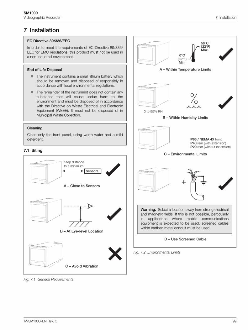
SM1000Videographic Recorder 7 Installation
IM/SM1000–EN Rev. O 99
7 Installation
7.1 Siting
EC Directive 89/336/EEC
In order to meet the requirements of EC Directive 89/336/EEC for EMC regulations, this product must not be used ina non-industrial environment.
End of Life Disposal
The instrument contains a small lithium battery whichshould be removed and disposed of responsibly inaccordance with local environmental regulations.
The remainder of the instrument does not contain anysubstance that will cause undue harm to theenvironment and must be disposed of in accordancewith the Directive on Waste Electrical and ElectronicEquipment (WEEE). It must not be disposed of inMunicipal Waste Collection.
Cleaning
Clean only the front panel, using warm water and a milddetergent.
Fig. 7.1 General Requirements
�6,�����������
(6���3:�����������
,6�����)�=������
������
���� ������� � ������
Fig. 7.2 Environmental Limits
�6>��'��#�������������
(6>��'��7������3������
�64������,�=�
,6������������������
.CE, ���E8"1�D�
CE, -�E8"1���
F � P%J �;
��//5��1�+F �����+C ���� ���� �.��������C ���� ������ �.�����
G
Warning. Select a location away from strong electricaland magnetic fields. If this is not possible, particularlyin applications where mobile communicationsequipment is expected to be used, screened cableswithin earthed metal conduit must be used.
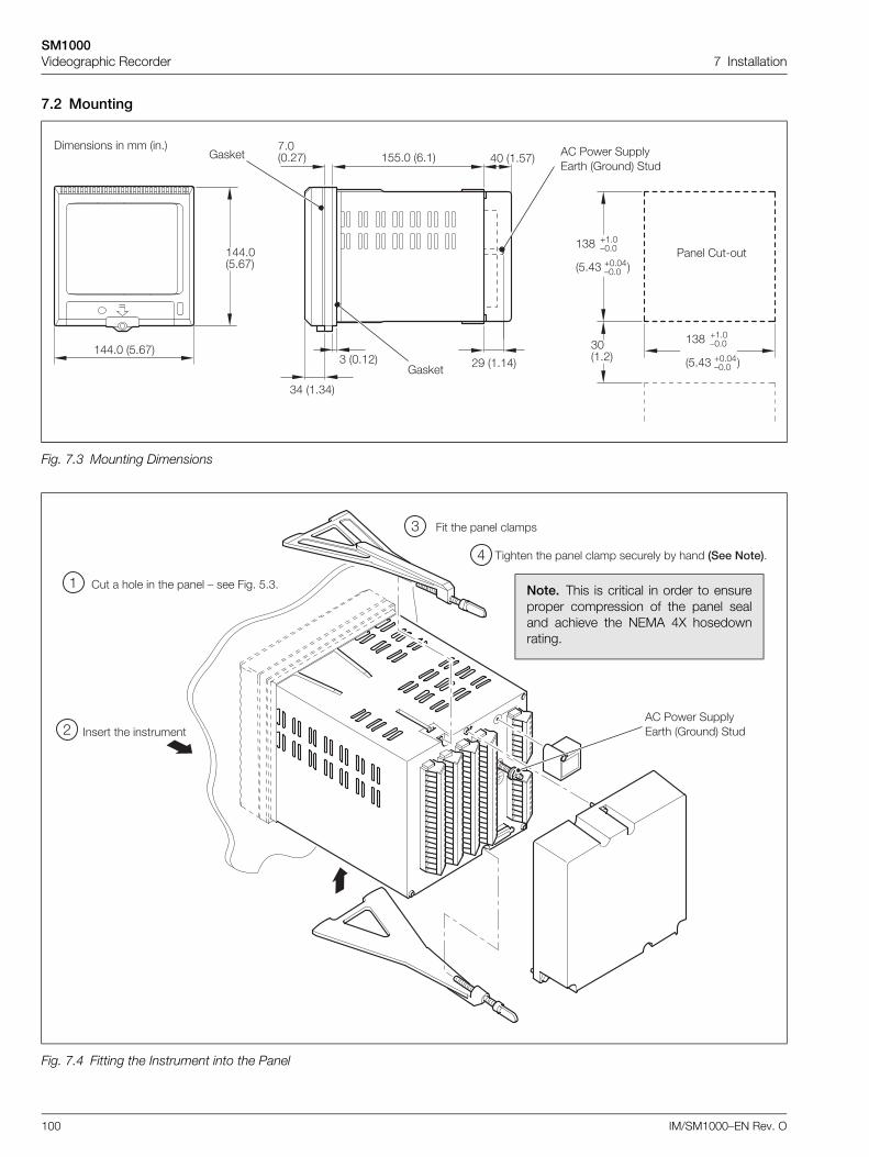
SM1000Videographic Recorder 7 Installation
100 IM/SM1000–EN Rev. O
7.2 Mounting
Fig. 7.3 Mounting Dimensions
Fig. 7.4 Fitting the Instrument into the Panel
�$$"F �%"&B�
�$$"F�%"&B�
5��� ��8��
#F��"!�
�#O
�%"$# �
Q�"F:F"F
QF"F$:F"F
�#O
�%"$# �
Q�"F:F"F
QF"F$:F"F
)������� � �� ��"�
#$ ��"#$�
# �F"�!� !P ��"�$�
B"F�F"!B� �%%"F �&"�� $F ��"%B�6��<�
6��<�
'� 5���� ������0��� �6����� ���
�� � ���� � �� ���� : ��� ���" %"#"
���� �� ������
�� �� ���� ������
,���� �� ���� ����� �������� *� ��� ����""
�
!
#
$
'� 5���� ������0��� �6����� ���
Note. This is critical in order to ensureproper compression of the panel sealand achieve the NEMA 4X hosedownrating.
SM1000Videographic Recorder 7 Installation
IM/SM1000–EN Rev. O 101
7.3 Electrical Connections
Warning.
The instrument is not fitted with a switch therefore a disconnecting device such as a switch or circuit breaker conforming tolocal safety standards must be fitted to the final installation. It must be fitted in close proximity to the instrument within easyreach of the operator and must be marked clearly as the disconnection device for the instrument.
The AC power supply earth (ground) cable must be connected to the earth (ground) stud .
Remove all power from supply, relay and any powered control circuits and high common mode voltages before accessingor making any connections.
Use cable appropriate for the load currents. The terminals accept cables up to 14AWG (2.5mm2).
The instrument conforms to Mains Power Input Insulation Category III. All other inputs and outputs conform to Category II.
All connections to secondary circuits must have basic insulation.
After installation, there must be no access to live parts, e.g. terminals.
Terminals for external circuits are for use only with equipment with no accessible live parts.
If the instrument is used in a manner not specified by the Company, the protection provided by the equipment may beimpaired.
All equipment connected to the instrument's terminals must comply with local safety standards (IEC 60950, EN601010-1).
Note.
Always route signal leads and power cables separately, preferably in earthed (grounded) metal conduit.
It is strongly recommended that screened cable is used for signal inputs and relay connections. Connect the screen to theearth (ground stud) – see Fig. 7.5, page 102.
Replacement of the internal battery (types Duracell DL2450 or Renata CR2450N 3V lithium cell) must be carried out by anapproved technician only.
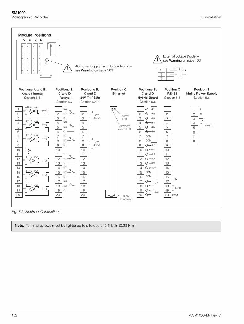
SM1000Videographic Recorder 7 Installation
102 IM/SM1000–EN Rev. O
Fig. 7.5 Electrical Connections
Note. Terminal screws must be tightened to a torque of 2.5 lbf.in (0.28 Nm).
1�������������
�
� ( , �
�������������(����� ����������� %"$
Q,;�
43- �4
�'
�,)
Q,;� �'
�,)
Q,;� �'
�,)
Q,;� �'
�,)
Q,;� �'
�,)
:
Q,;�
43- �4
�'
�,)
:
:
:
:
:
�!#$%&BOP�F���!�#�$�%�&�B�O�P!F
43- �4
43- �4
43- �4
43- �4
���������(A,�������3�
����� %"B
�!#$%&BOP�F���!�#�$�%�&�B�O�P!F
9�
9>
�
9�
9>
�
9�
9>
�
9�
9>
�
9�
9>
�
9�
9>
�
,�����10)
������/����� � 10)
�=$%������
��������,��'���
�!#$%&BOP�F���!�#�$�%�&�B�O�P!F
Q
:
!$4$%�'
Q
:
!$4$%�'
���������(A,����
�+)#D��4������ %"$"$
�!#$%&BOP�F���!�#�$�%�&�B�O�P!F
���
��!
��#
��$
��%
��&
���
��!
��#
��$
��%
��&
�>�
�>�
�>�
�>�
Q
:�F�
Q
:�F!
���������(A,����
73=���(��������� %"O
G6
�!#$%&BO
1
9
Q:
!$4 )�
���������1������*������3
����� %"&
Q:
,.
Q
:,./�.
�>�
�!#$%&BOP�F���!�#�$�%�&�B�O�P!F
��������,��+%.
����� %"%
AC Power Supply Earth (Ground) Stud – see Warning on page 101.
External Voltage Divider – see Warning on page 103.
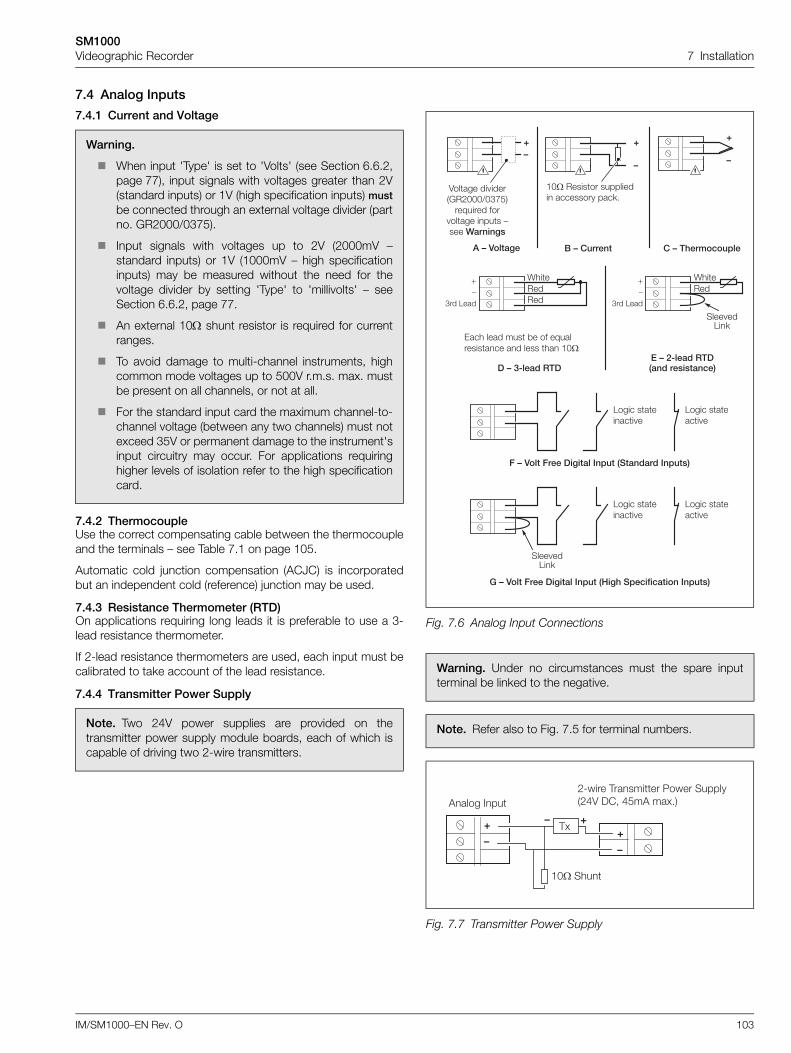
SM1000Videographic Recorder 7 Installation
IM/SM1000–EN Rev. O 103
7.4 Analog Inputs
7.4.1 Current and Voltage
7.4.2 ThermocoupleUse the correct compensating cable between the thermocoupleand the terminals – see Table 7.1 on page 105.
Automatic cold junction compensation (ACJC) is incorporatedbut an independent cold (reference) junction may be used.
7.4.3 Resistance Thermometer (RTD)On applications requiring long leads it is preferable to use a 3-lead resistance thermometer.
If 2-lead resistance thermometers are used, each input must becalibrated to take account of the lead resistance.
7.4.4 Transmitter Power Supply
Warning.
When input 'Type' is set to 'Volts' (see Section 6.6.2,page 77), input signals with voltages greater than 2V(standard inputs) or 1V (high specification inputs) mustbe connected through an external voltage divider (partno. GR2000/0375).
Input signals with voltages up to 2V (2000mV –standard inputs) or 1V (1000mV – high specificationinputs) may be measured without the need for thevoltage divider by setting 'Type' to 'millivolts' – seeSection 6.6.2, page 77.
An external 10 shunt resistor is required for currentranges.
To avoid damage to multi-channel instruments, highcommon mode voltages up to 500V r.m.s. max. mustbe present on all channels, or not at all.
For the standard input card the maximum channel-to-channel voltage (between any two channels) must notexceed 35V or permanent damage to the instrument'sinput circuitry may occur. For applications requiringhigher levels of isolation refer to the high specificationcard.
Note. Two 24V power supplies are provided on thetransmitter power supply module boards, each of which iscapable of driving two 2-wire transmitters.
Fig. 7.6 Analog Input Connections
Warning. Under no circumstances must the spare inputterminal be linked to the negative.
Note. Refer also to Fig. 7.5 for terminal numbers.
Fig. 7.7 Transmitter Power Supply
4����� �� �����6�!FFF/F#B%���M����� ���
����� ���� :��� >����� �
�6)����
�F� ������� ��������� ��������� ���<"
(6,����� ,6#'��������
0��� ���� ��� *� �� �M����������� �� ���� �� �F�
�6-:����#��6�:����#� �����������"
Q:
#�� 1���
K���������
G
6
K������
���� ��1�<
Q:
#�� 1���
86)���8��� ��������� ��������������"
1���� ������� �
1���� ������ �
G
6
G6
�6)���8��� ��������� 7� '����0�������������"
1���� ������� �
1���� ������ �
���� ��1�<
G
6
G
6
G6
!8���� ,������� 5���� �������!$4 )�- $%�' ��."�'���� ���
�F� ���
,.
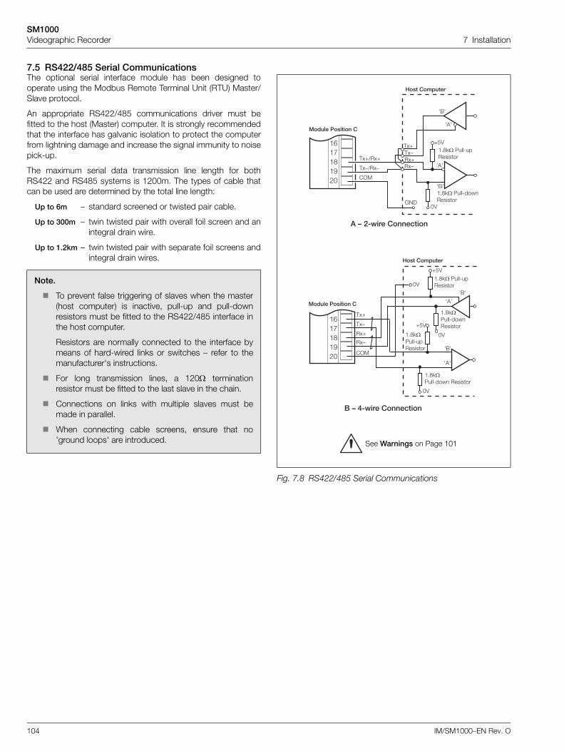
SM1000Videographic Recorder 7 Installation
104 IM/SM1000–EN Rev. O
7.5 RS422/485 Serial CommunicationsThe optional serial interface module has been designed tooperate using the Modbus Remote Terminal Unit (RTU) Master/Slave protocol.
An appropriate RS422/485 communications driver must befitted to the host (Master) computer. It is strongly recommendedthat the interface has galvanic isolation to protect the computerfrom lightning damage and increase the signal immunity to noisepick-up.
The maximum serial data transmission line length for bothRS422 and RS485 systems is 1200m. The types of cable thatcan be used are determined by the total line length:
Up to 6m – standard screened or twisted pair cable.
Up to 300m – twin twisted pair with overall foil screen and anintegral drain wire.
Up to 1.2km – twin twisted pair with separate foil screens andintegral drain wires.
Note.
To prevent false triggering of slaves when the master(host computer) is inactive, pull-up and pull-downresistors must be fitted to the RS422/485 interface inthe host computer.
Resistors are normally connected to the interface bymeans of hard-wired links or switches – refer to themanufacturer's instructions.
For long transmission lines, a 120 terminationresistor must be fitted to the last slave in the chain.
Connections on links with multiple slaves must bemade in parallel.
When connecting cable screens, ensure that no'ground loops' are introduced.
Fig. 7.8 RS422/485 Serial Communications
7���,������
Q%4
F4
7'7
7(7
�"O<�5���8����������
�"O<� 5���8���������F4
Q%4
F4
7'7
7(7
�"O<�5���8��� �������
�"O<�5���8���������
�.Q
�.:
,.:
,.Q
�>�
1������������,
(6+:*��,��������
Q%4
F4
�"O<� 5���8���������
�"O<� 5���8����������
7���,������
�.:�.Q,.:,.Q
7'7
7'7
7(7
7(7
69)
�&�B�O�P!F
,.Q/�.Q
,.:/�.:
�>�
1������������,
�6�:*��,��������
�&�B�O�P!F
See Warnings on Page 101
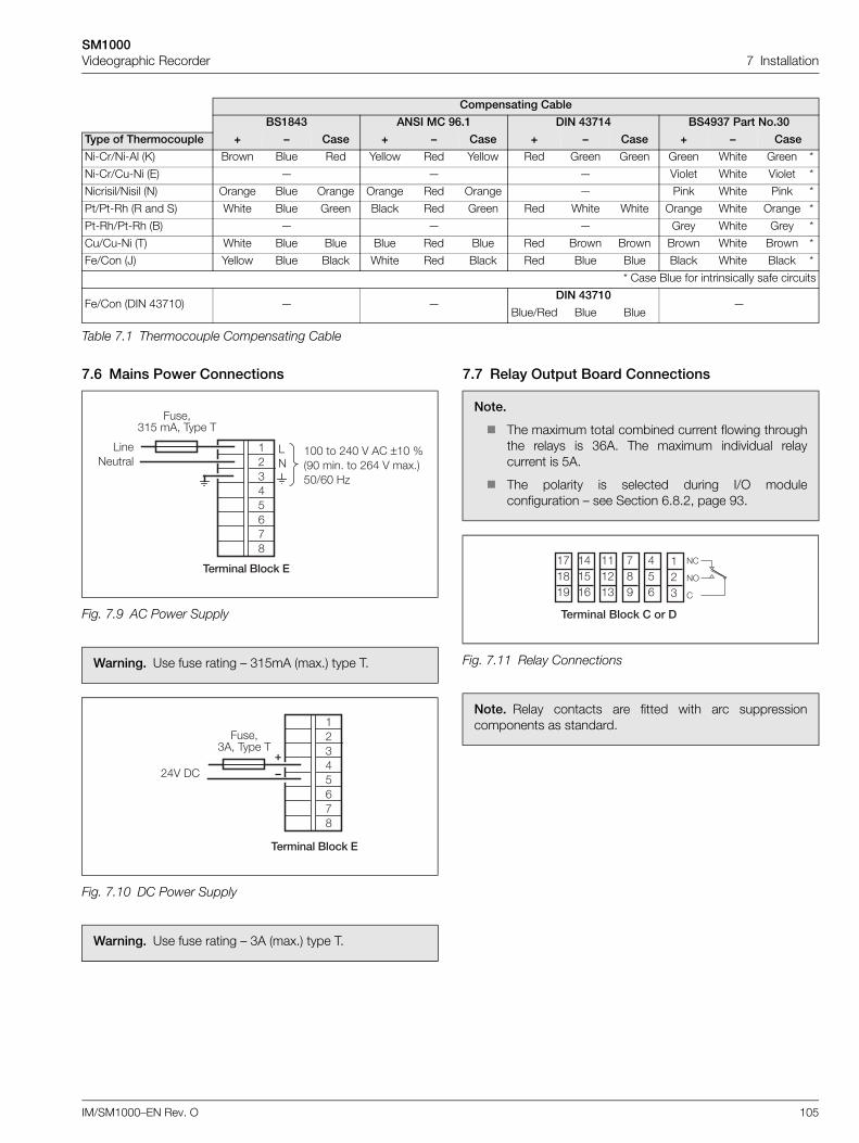
SM1000Videographic Recorder 7 Installation
IM/SM1000–EN Rev. O 105
7.6 Mains Power Connections 7.7 Relay Output Board Connections
Compensating Cable
BS1843 ANSI MC 96.1 DIN 43714 BS4937 Part No.30
Type of Thermocouple + – Case + – Case + – Case + – Case
Ni-Cr/Ni-Al (K) Brown Blue Red Yellow Red Yellow Red Green Green Green White Green *
Ni-Cr/Cu-Ni (E) — — — Violet White Violet *
Nicrisil/Nisil (N) Orange Blue Orange Orange Red Orange — Pink White Pink *
Pt/Pt-Rh (R and S) White Blue Green Black Red Green Red White White Orange White Orange *
Pt-Rh/Pt-Rh (B) — — — Grey White Grey *
Cu/Cu-Ni (T) White Blue Blue Blue Red Blue Red Brown Brown Brown White Brown *
Fe/Con (J) Yellow Blue Black White Red Black Red Blue Blue Black White Black *
* Case Blue for intrinsically safe circuits
Fe/Con (DIN 43710) — —DIN 43710
—Blue/Red Blue Blue
Table 7.1 Thermocouple Compensating Cable
Fig. 7.9 AC Power Supply
Warning. Use fuse rating – 315mA (max.) type T.
Fig. 7.10 DC Power Supply
Warning. Use fuse rating – 3A (max.) type T.
Terminal Block E
LN
100 to 240 V AC ±10 %(90 min. to 264 V max.)50/60 Hz
12345678
LineNeutral
Fuse,315 mA, Type T
!$4 )�
����-#'- ,��� ,
#������(���H�
�!#$%&BO
G
6
Note.
The maximum total combined current flowing throughthe relays is 36A. The maximum individual relaycurrent is 5A.
The polarity is selected during I/O moduleconfiguration – see Section 6.8.2, page 93.
Fig. 7.11 Relay Connections
Note. Relay contacts are fitted with arc suppressioncomponents as standard.
�B�O�P
�$�%�&
���!�#
BOP
$%&
�!#
#������(���H,���
9�
9>
�
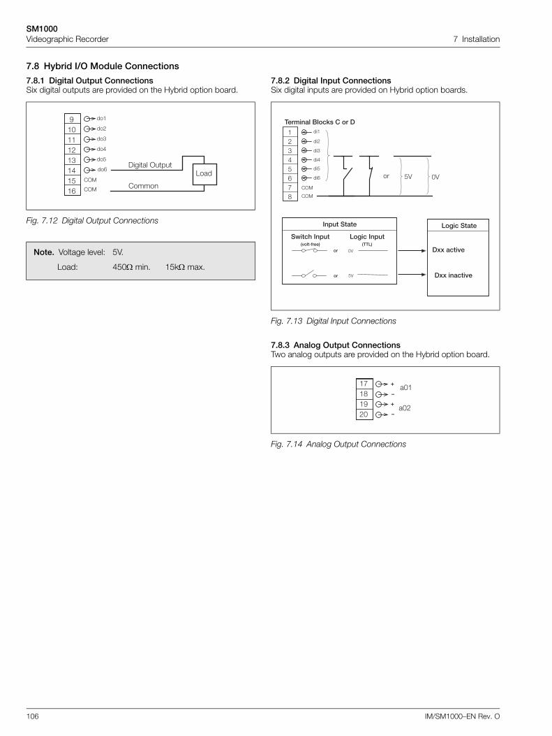
SM1000Videographic Recorder 7 Installation
106 IM/SM1000–EN Rev. O
7.8 Hybrid I/O Module Connections
7.8.1 Digital Output ConnectionsSix digital outputs are provided on the Hybrid option board.
7.8.2 Digital Input ConnectionsSix digital inputs are provided on Hybrid option boards.
7.8.3 Analog Output ConnectionsTwo analog outputs are provided on the Hybrid option board.
Fig. 7.12 Digital Output Connections
Note. Voltage level: 5V.
Load: 450 min. 15k max.
)����� >���
�����
1���
P�F���!�#�$�%�&
���
��!
��#
��$
��%
��&
�>�
�>�
Fig. 7.13 Digital Input Connections
Fig. 7.14 Analog Output Connections
���
��!
��#
��$
��%
��&
�>�
�>�
#������(���H�,���
���������
�DD�����
�*���'����� ����:0�"
��
��
%4
F4
�� ������� ##�"
�� ������
�DD�������
�!#$%&BO
%4�� F4
�F�
�F!
�B�O�P!F
G
6
G
6
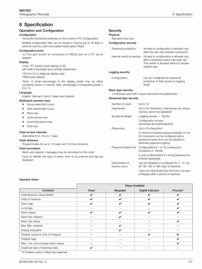
SM1000Videographic Recorder 8 Specification
IM/SM1000–EN Rev. O 107
8 SpecificationOperation and ConfigurationConfiguration
Via tactile membrane switches on front panel or PC Configuration
Multiple configuration files can be stored in internal (up to 16 files) orexternal memory (with removable media option fitted)
Configuration ports3.5 mm jack socket for connection to RS232 port on a PC via anadapter
DisplayColor, TFT, liquid crystal display (LCD)with built-in backlight and contrast adjustment
125 mm (5 in.) diagonal display area, 76800 pixel display*
*Note. A small percentage ot the display pixels may be eitherconstantly active or inactive. Max. percentage of inoperative pixels <0.01 %
Language English, German, French, Italian and Spanish
Dedicated operator keys Group select/left cursor
View select/right cursor
Menu key
Up/Increment key
Down/Decrement key
Enter key
Chart screen intervalsSelectable from 18 s to 7 days
Chart divisionsProgrammable for up to 10 major and 10 minor divisions
Chart annotationAlarm and operator messages may be annotated on the chart
Icons to identify the type of event, time of occurrence and tag aredisplayed
SecurityPhysical
Standard door lock
Configuration security
Logging security
Basic type security4 individual users with unique username and passwords
Advanced type security
Operator Views
Password protection Access to configuration is allowed only after the user has entered a password
Internal switch protection Access to configuration is allowed only after a hardware switch has been set. This switch is situated behind a tamper-evident seal
Configuration Can be configured for password protection or free access to logging levels
Number of users Up to 12
Usernames Up to 20 characters, Usernames are unique (names cannot be repeated)
Access privileges Logging access — Yes/No
Configuration accessNone/load file only/limited/full
Passwords Up to 20 characters
A minimum required password length of 4 to 20 characters can be configured and a password expiry time can be applied to eliminate password ageing
Password failure limit Configurable for 1 to 10 consecutive occasions or 'infinite'
A user is deactivated if a wrong password is entered repeatedly
Deactivation of inactive users
Can be disabled or configured for 7, 14, 30, 60, 90, 180 or 360 days of inactivity
Users are deactivated (by removal of access privileges) after a period of inactivity
Views Available
Contents Chart Bargraph Digital Indicator Process*
Instantaneous values/states
Units of measure
Short tags
Long tags — — —
Alarm status
Alarm trip markers — — —
Alarm trip values — — —
Max./Min. markers — — —
Analog bargraphs — — —
Totalizer values & units of measure — —
Totalizer tags — — —
Max., min. and average batch values — — —
Graphical view of historical data — — —
* If Totalizer option is fitted and selected
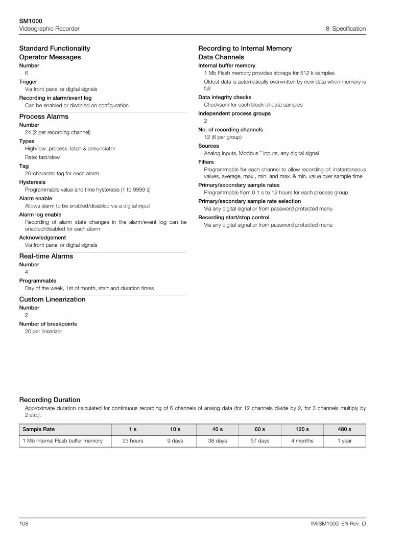
SM1000Videographic Recorder 8 Specification
108 IM/SM1000–EN Rev. O
Standard FunctionalityOperator MessagesNumber
6
TriggerVia front panel or digital signals
Recording in alarm/event logCan be enabled or disabled on configuration
Process AlarmsNumber
24 (2 per recording channel)
TypesHigh/low: process, latch & annunciator
Rate: fast/slow
Tag20-character tag for each alarm
HysteresisProgrammable value and time hysteresis (1 to 9999 s)
Alarm enableAllows alarm to be enabled/disabled via a digital input
Alarm log enableRecording of alarm state changes in the alarm/event log can beenabled/disabled for each alarm
AcknowledgementVia front panel or digital signals
Real-time AlarmsNumber
4
ProgrammableDay of the week, 1st of month, start and duration times
Custom LinearizationNumber
2
Number of breakpoints20 per linearizer
Recording to Internal MemoryData ChannelsInternal buffer memory
1 Mb Flash memory provides storage for 512 k samples
Oldest data is automatically overwritten by new data when memory isfull
Data integrity checksChecksum for each block of data samples
Independent process groups2
No. of recording channels12 (6 per group)
SourcesAnalog inputs, Modbus™ inputs, any digital signal
FiltersProgrammable for each channel to allow recording of: instantaneousvalues, average, max., min. and max. & min. value over sample time
Primary/secondary sample ratesProgrammable from 0.1 s to 12 hours for each process group
Primary/secondary sample rate selectionVia any digital signal or from password protected menu
Recording start/stop controlVia any digital signal or from password protected menu
Recording DurationApproximate duration calculated for continuous recording of 6 channels of analog data (for 12 channels divide by 2, for 3 channels multiply by2 etc.).
Sample Rate 1 s 10 s 40 s 60 s 120 s 480 s
1 Mb Internal Flash buffer memory 23 hours 9 days 38 days 57 days 4 months 1 year
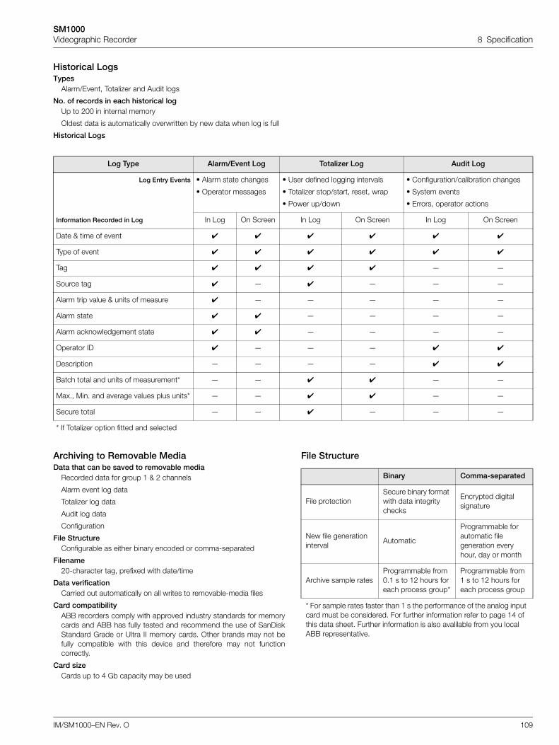
SM1000Videographic Recorder 8 Specification
IM/SM1000–EN Rev. O 109
Historical LogsTypes
Alarm/Event, Totalizer and Audit logs
No. of records in each historical logUp to 200 in internal memory
Oldest data is automatically overwritten by new data when log is full
Historical Logs
Archiving to Removable MediaData that can be saved to removable media
Recorded data for group 1 & 2 channels
Alarm event log data
Totalizer log data
Audit log data
Configuration
File StructureConfigurable as either binary encoded or comma-separated
Filename20-character tag, prefixed with date/time
Data verificationCarried out automatically on all writes to removable-media files
Card compatibilityABB recorders comply with approved industry standards for memorycards and ABB has fully tested and recommend the use of SanDiskStandard Grade or Ultra II memory cards. Other brands may not befully compatible with this device and therefore may not functioncorrectly.
Card sizeCards up to 4 Gb capacity may be used
File Structure
Log Type Alarm/Event Log Totalizer Log Audit Log
Log Entry Events • Alarm state changes
• Operator messages
• User defined logging intervals
• Totalizer stop/start, reset, wrap
• Power up/down
• Configuration/calibration changes
• System events
• Errors, operator actions
Information Recorded in Log In Log On Screen In Log On Screen In Log On Screen
Date & time of event
Type of event
Tag — —
Source tag — — — —
Alarm trip value & units of measure — — — — —
Alarm state — — — —
Alarm acknowledgement state — — — —
Operator ID — — —
Description — — — —
Batch total and units of measurement* — — — —
Max., Min. and average values plus units* — — — —
Secure total — — — — —
* If Totalizer option fitted and selected
Binary Comma-separated
File protectionSecure binary format with data integrity checks
Encrypted digital signature
New file generation interval
Automatic
Programmable for automatic file generation every hour, day or month
Archive sample ratesProgrammable from 0.1 s to 12 hours for each process group*
Programmable from 1 s to 12 hours for each process group
* For sample rates faster than 1 s the performance of the analog input card must be considered. For further information refer to page 14 of this data sheet. Further information is also avalilable from you local ABB representative.
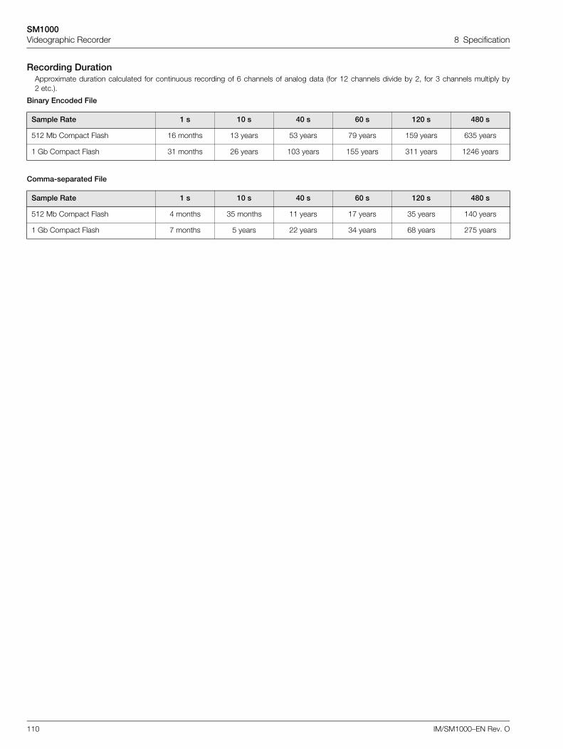
SM1000Videographic Recorder 8 Specification
110 IM/SM1000–EN Rev. O
Recording DurationApproximate duration calculated for continuous recording of 6 channels of analog data (for 12 channels divide by 2, for 3 channels multiply by2 etc.).
Binary Encoded File
Comma-separated File
Sample Rate 1 s 10 s 40 s 60 s 120 s 480 s
512 Mb Compact Flash 16 months 13 years 53 years 79 years 159 years 635 years
1 Gb Compact Flash 31 months 26 years 103 years 155 years 311 years 1246 years
Sample Rate 1 s 10 s 40 s 60 s 120 s 480 s
512 Mb Compact Flash 4 months 35 months 11 years 17 years 35 years 140 years
1 Gb Compact Flash 7 months 5 years 22 years 34 years 68 years 275 years
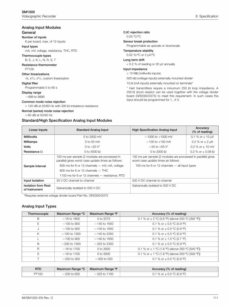
SM1000Videographic Recorder 8 Specification
IM/SM1000–EN Rev. O 111
Analog Input ModulesGeneralNumber of inputs
6 per board, max. of 12 inputs
Input typesmA, mV, voltage, resistance, THC, RTD
Thermocouple typesB, E, J, K, L, N, R, S, T
Resistance thermometerPT100
Other linearizationsx, x3/2, x5/2, custom linearization
Digital filterProgrammable 0 to 60 s
Display range—999 to 9999
Common mode noise rejection> 120 dB at 50/60 Hz with 300 imbalance resistance
Normal (series) mode noise rejection> 60 dB at 50/60 Hz
CJC rejection ratio0.05 ºC/ºC
Sensor break protectionProgrammable as upscale or downscale
Temperature stability0.02 %/ºC or 2 µV/ºC
Long term drift< 0.2 % of reading or 20 µV annually
Input impedance> 10 M (millivolts inputs)
500 k (voltage inputs) externally mounted divider
10 (mA inputs) externally mounted on terminals*
* Hart transmitters require a minumum 250 loop impedance. A250 shunt resistor can be used together with the voltage dividerboard (GR2000/0375) to meet this requirement. In such cases theinput should be programmed for 1...5 V.
Standard/High Specification Analog Input Modules
Analog Input Types
Linear Inputs Standard Analog Input High Specification Analog InputAccuracy
(% of reading)
Milllivolts
Milliamps
Volts
Resistance
0 to 2000 mV
0 to 50 mA
0 to +20 V*
0 to 5000
—1000 to +1000 mV
—100 to +100 mA
—50 to +50 V*
0 to 2000
0.1 % or ± 10 µV
0.2 % or ± 2 µA
0.2 % or ± 10 mV
0.2 % or ± 0.08
Sample Interval
100 ms per sample (2 modules are processed in parallel) gives worst case update times as follows:
100 ms per sample (2 modules are processed in parallel) gives worst case update times as follows:
600 ms for 6 or 12 channels — mV, mA, voltage
800 ms for 6 or 12 channels — THC
1100 ms for 6 or 12 channels — resistance, RTD
100 ms for 6 or 12 channels — all input types
Input Isolation 35 V DC channel-to-channel 500 V DC channel-to-channel
Isolation from Rest of Instrument Galvanically isolated to 500 V DC
Galvanically isolated to 500 V DC
*Requires external voltage divider board Part No. GR2000/0375
Thermocouple Maximum Range ºC Maximum Range ºF Accuracy (% of reading)
B —18 to 1800 0 to 3270 0.1 % or ± 2 ºC (3.6 ºF) (above 200 ºC [392 ºF])
E —100 to 900 —140 to 1650 0.1 % or ± 0.5 ºC (0.9 ºF)
J —100 to 900 —140 to 1650 0.1 % or ± 0.5 ºC (0.9 ºF)
K —100 to 1300 —140 to 2350 0.1 % or ± 0.5 ºC (0.9 ºF)
L —100 to 900 —140 to 1650 0.1 % or ± 1.5 ºC (2.7 ºF)
N —200 to 1300 —325 to 2350 0.1 % or ± 0.5 ºC (0.9 ºF)
R —18 to 1700 0 to 3000 0.1 % or ± 1 ºC (1.8 ºF) (above 300 ºC [540 ºF])
S —18 to 1700 0 to 3000 0.1 % or ± 1 ºC (1.8 ºF) (above 200 ºC [392 ºF])
T —250 to 300 —400 to 550 0.1 % or ± 0.5 ºC (0.9 ºF)
RTD Maximum Range ºC Maximum Range ºF Accuracy (% of reading)
PT100 —200 to 600 —325 to 1100 0.1 % or ± 0.5 ºC (0.9 ºF)
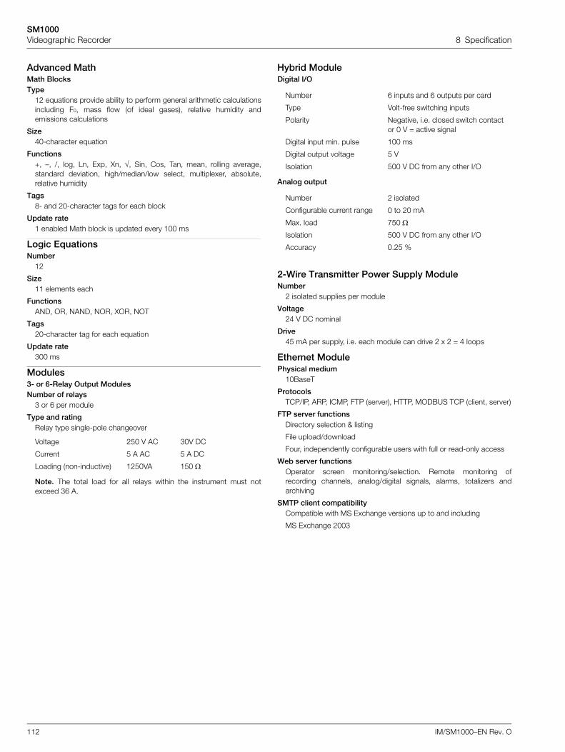
SM1000Videographic Recorder 8 Specification
112 IM/SM1000–EN Rev. O
Advanced MathMath BlocksType
12 equations provide ability to perform general arithmetic calculationsincluding F0, mass flow (of ideal gases), relative humidity andemissions calculations
Size40-character equation
Functions+, –, /, log, Ln, Exp, Xn, , Sin, Cos, Tan, mean, rolling average,standard deviation, high/median/low select, multiplexer, absolute,relative humidity
Tags8- and 20-character tags for each block
Update rate1 enabled Math block is updated every 100 ms
Logic EquationsNumber
12
Size11 elements each
FunctionsAND, OR, NAND, NOR, XOR, NOT
Tags20-character tag for each equation
Update rate300 ms
Modules3- or 6-Relay Output ModulesNumber of relays
3 or 6 per module
Type and ratingRelay type single-pole changeover
Note. The total load for all relays within the instrument must notexceed 36 A.
Hybrid ModuleDigital I/O
Analog output
2-Wire Transmitter Power Supply ModuleNumber
2 isolated supplies per module
Voltage24 V DC nominal
Drive45 mA per supply, i.e. each module can drive 2 x 2 = 4 loops
Ethernet ModulePhysical medium
10BaseT
ProtocolsTCP/IP, ARP, ICMP, FTP (server), HTTP, MODBUS TCP (client, server)
FTP server functionsDirectory selection & listing
File upload/download
Four, independently configurable users with full or read-only access
Web server functionsOperator screen monitoring/selection. Remote monitoring ofrecording channels, analog/digital signals, alarms, totalizers andarchiving
SMTP client compatibilityCompatible with MS Exchange versions up to and including
MS Exchange 2003
Voltage 250 V AC 30V DC
Current 5 A AC 5 A DC
Loading (non-inductive) 1250VA 150
Number 6 inputs and 6 outputs per card
Type Volt-free switching inputs
Polarity Negative, i.e. closed switch contact or 0 V = active signal
Digital input min. pulse 100 ms
Digital output voltage 5 V
Isolation 500 V DC from any other I/O
Number 2 isolated
Configurable current range 0 to 20 mA
Max. load 750
Isolation 500 V DC from any other I/O
Accuracy 0.25 %
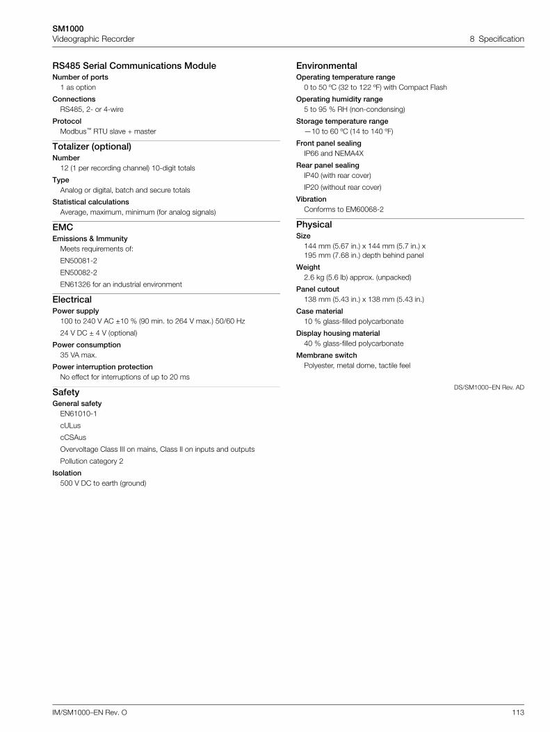
SM1000Videographic Recorder 8 Specification
IM/SM1000–EN Rev. O 113
RS485 Serial Communications ModuleNumber of ports
1 as option
ConnectionsRS485, 2- or 4-wire
ProtocolModbus™ RTU slave + master
Totalizer (optional)Number
12 (1 per recording channel) 10-digit totals
TypeAnalog or digital, batch and secure totals
Statistical calculationsAverage, maximum, minimum (for analog signals)
EMCEmissions & Immunity
Meets requirements of:
EN50081-2
EN50082-2
EN61326 for an industrial environment
ElectricalPower supply
100 to 240 V AC ±10 % (90 min. to 264 V max.) 50/60 Hz
24 V DC ± 4 V (optional)
Power consumption35 VA max.
Power interruption protectionNo effect for interruptions of up to 20 ms
SafetyGeneral safety
EN61010-1
cULus
cCSAus
Overvoltage Class III on mains, Class II on inputs and outputs
Pollution category 2
Isolation500 V DC to earth (ground)
EnvironmentalOperating temperature range
0 to 50 ºC (32 to 122 ºF) with Compact Flash
Operating humidity range5 to 95 % RH (non-condensing)
Storage temperature range—10 to 60 ºC (14 to 140 ºF)
Front panel sealingIP66 and NEMA4X
Rear panel sealingIP40 (with rear cover)
IP20 (without rear cover)
VibrationConforms to EM60068-2
PhysicalSize
144 mm (5.67 in.) x 144 mm (5.7 in.) x195 mm (7.68 in.) depth behind panel
Weight2.6 kg (5.6 lb) approx. (unpacked)
Panel cutout138 mm (5.43 in.) x 138 mm (5.43 in.)
Case material10 % glass-filled polycarbonate
Display housing material40 % glass-filled polycarbonate
Membrane switchPolyester, metal dome, tactile feel
DS/SM1000–EN Rev. AD
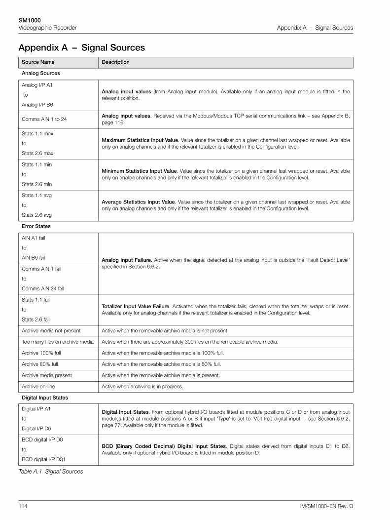
SM1000Videographic Recorder Appendix A – Signal Sources
114 IM/SM1000–EN Rev. O
Appendix A – Signal SourcesSource Name Description
Analog Sources
Analog I/P A1
to
Analog I/P B6
Analog input values (from Analog input module). Available only if an analog input module is fitted in therelevant position.
Comms AIN 1 to 24Analog input values. Received via the Modbus/Modbus TCP serial communications link – see Appendix B,page 116.
Stats 1.1 max
to
Stats 2.6 max
Maximum Statistics Input Value. Value since the totalizer on a given channel last wrapped or reset. Availableonly on analog channels and if the relevant totalizer is enabled in the Configuration level.
Stats 1.1 min
to
Stats 2.6 min
Minimum Statistics Input Value. Value since the totalizer on a given channel last wrapped or reset. Availableonly on analog channels and only if the relevant totalizer is enabled in the Configuration level.
Stats 1.1 avg
to
Stats 2.6 avg
Average Statistics Input Value. Value since the totalizer on a given channel last wrapped or reset. Availableonly on analog channels and only if the relevant totalizer is enabled in the Configuration level.
Error States
AIN A1 fail
to
AIN B6 fail Analog Input Failure. Active when the signal detected at the analog input is outside the 'Fault Detect Level'specified in Section 6.6.2.Comms AIN 1 fail
to
Comms AIN 24 fail
Stats 1.1 fail
to
Stats 2.6 fail
Totalizer Input Value Failure. Activated when the totalizer fails, cleared when the totalizer wraps or is reset.Available only for analog channels if the relevant totalizer is enabled in the Configuration level.
Archive media not present Active when the removable archive media is not present.
Too many files on archive media Active when there are approximately 300 files on the removable archive media.
Archive 100% full Active when the removable archive media is 100% full.
Archive 80% full Active when the removable archive media is 80% full.
Archive media present Active when the removable archive media is present.
Archive on-line Active when archiving is in progress.
Digital Input States
Digital I/P A1
to
Digital I/P D6
Digital Input States. From optional hybrid I/O boards fitted at module positions C or D or from analog inputmodules fitted at module positions A or B if input 'Type' is set to 'Volt free digital input' – see Section 6.6.2,page 77. Available only if the module is fitted.
BCD digital I/P D0
to
BCD digital I/P D31
BCD (Binary Coded Decimal) Digital Input States. Digital states derived from digital inputs D1 to D6.Available only if optional hybrid I/O board is fitted in module position D.
Table A.1 Signal Sources
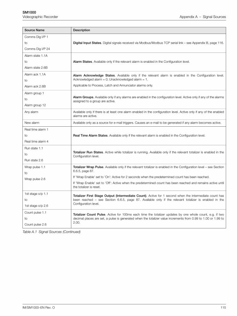
SM1000Videographic Recorder Appendix A – Signal Sources
IM/SM1000–EN Rev. O 115
Comms Dig I/P 1
to
Comms Dig I/P 24
Digital Input States. Digital signals received via Modbus/Modbus TCP serial link – see Appendix B, page 116.
Alarm state 1.1A
to
Alarm state 2.6B
Alarm States. Available only if the relevant alarm is enabled in the Configuration level.
Alarm ack 1.1A
to
Alarm ack 2.6B
Alarm Acknowledge States. Available only if the relevant alarm is enabled in the Configuration level.Acknowledged alarm = 0; Unacknowledged alarm = 1.
Applicable to Process, Latch and Annunciator alarms only.
Alarm group 1
to
Alarm group 12
Alarm Groups. Available only if any alarms are enabled in the configuration level. Active only if any of the alarmsassigned to a group are active.
Any alarm Available only if there is at least one alarm enabled in the configuration level. Active only if any of the enabledalarms are active.
New alarm Available only as a source for e-mail triggers. Causes an e-mail to be generated if any alarm becomes active.
Real time alarm 1
to
Real time alarm 4
Real Time Alarm States. Available only if the relevant alarm is enabled in the Configuration level.
Run state 1.1
to
Run state 2.6
Totalizer Run States. Active while totalizer is running. Available only if the relevant totalizer is enabled in theConfiguration level.
Wrap pulse 1.1
to
Wrap pulse 2.6
Totalizer Wrap Pulse. Available only if the relevant totalizer is enabled in the Configuration level – see Section6.6.5, page 87.
If 'Wrap Enable' set to 'On': Active for 2 seconds when the predetermined count has been reached.
If 'Wrap Enable' set to 'Off': Active when the predetermined count has been reached and remains active untilthe totalizer is reset.
1st stage o/p 1.1
to
1st stage o/p 2.6
Totalizer First Stage Output (Intermediate Count). Active for 1 second when the intermediate count hasbeen reached – see Section 6.6.5, page 87. Available only if the relevant totalizer is enabled in theConfiguration level.
Count pulse 1.1
to
Count pulse 2.6
Totalizer Count Pulse. Active for 100ms each time the totalizer updates by one whole count, e.g. if twodecimal places are set, a pulse is generated when the totalizer value increments from 0.99 to 1.00 or 1.99 to2.00.
Source Name Description
Table A.1 Signal Sources (Continued)
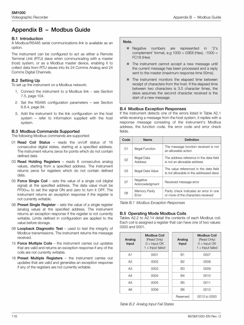
SM1000Videographic Recorder Appendix B – Modbus Guide
116 IM/SM1000–EN Rev. O
Appendix B – Modbus GuideB.1 IntroductionA Modbus/RS485 serial communications link is available as anoption.
The instrument can be configured to act as either a RemoteTerminal Unit (RTU) slave when communicating with a master(host) system, or as a Modbus master device, enabling it tocollect data from RTU slaves into its 24 Comms Analog and 24Comms Digital Channels.
B.2 Setting UpTo set up the instrument on a Modbus network:
1. Connect the instrument to a Modbus link – see Section7.5, page 104.
2. Set the RS485 configuration parameters – see Section6.8.4, page 94.
3. Add the instrument to the link configuration on the hostsystem – refer to information supplied with the hostsystem.
B.3 Modbus Commands SupportedThe following Modbus commands are supported:
B.4 Modbus Exception ResponsesIf the instrument detects one of the errors listed in Table A2.1while receiving a message from the host system, it replies with aresponse message consisting of the instrument's Modbusaddress, the function code, the error code and error checkfields.
B.5 Operating Mode Modbus CoilsTables A2.2 to A2.14 detail the contents of each Modbus coil.Each coil is assigned a register that can have one of two values:0000 and 0001.
01 Read Coil Status – reads the on/off status of 16consecutive digital states, starting at a specified address.The instrument returns zeros for points which do not containdefined data
03 Read Holding Registers – reads 8 consecutive analogvalues, starting from a specified address. The instrumentreturns zeros for registers which do not contain defineddata.
05 Force Single Coil – sets the value of a single coil (digitalsignal) at the specified address. The data value must beFF00Hex to set the signal ON and zero to turn it OFF. Theinstrument returns an exception response if the register isnot currently writable.
06 Preset Single Register – sets the value of a single register(analog value) at the specified address. The instrumentreturns an exception response if the register is not currentlywritable. Limits defined in configuration are applied to thevalue before storage.
08 Loopback Diagnostic Test – used to test the integrity ofModbus transmissions. The instrument returns the messagereceived.
15 Force Multiple Coils – the instrument carries out updatesthat are valid and returns an exception response if any of thecoils are not currently writable.
16 Preset Multiple Registers – the instrument carries outupdates that are valid and generates an exception responseif any of the registers are not currently writable.
Note.
Negative numbers are represented in '2'scomplement' format, e.g 1000 = 03E8 (Hex), -1000 =FC18 (Hex)
The instrument cannot accept a new message untilthe current message has been processed and a replysent to the master (maximum response time 50ms).
The instrument monitors the elapsed time betweenreceipt of characters from the host. If the elapsed timebetween two characters is 3.5 character times, theslave assumes the second character received is thestart of a new message.
Code Name Definition
01 Illegal FunctionThe message function received is notan allowable action
02Illegal Data Address
The address reference in the data fieldis not an allowable address
03 Illegal Data ValueThe value referenced in the data fieldis not allowable in the addressed slave
07Negative Acknowledgment
Received message error
08Memory Parity Error
Parity check indicates an error in oneor more of the characters received
Table B.1 Modbus Exception Responses
Analog Input
Modbus Coil (Read Only)
0 = Input OK 1 = Input failed
Analog Input
Modbus Coil(Read Only)
0 = Input OK1 = Input failed
A1 0001 B1 0007
A2 0002 B2 0008
A3 0003 B3 0009
A4 0004 B4 0010
A5 0005 B5 0011
A6 0006 B6 0012
Reserved 0013 to 0050
Table B.2 Analog Input Fail States
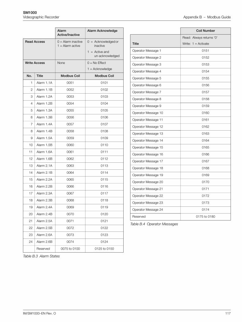
SM1000Videographic Recorder Appendix B – Modbus Guide
IM/SM1000–EN Rev. O 117
Alarm Active/Inactive
Alarm Acknowledge
Read Access 0 = Alarm inactive1 = Alarm active
0 = Acknowledged or inactive
1 = Active and un-acknowledged
Write Access None 0 = No Effect
1 = Acknowledge
No. Title Modbus Coil Modbus Coil
1 Alarm 1.1A 0051 0101
2 Alarm 1.1B 0052 0102
3 Alarm 1.2A 0053 0103
4 Alarm 1.2B 0054 0104
5 Alarm 1.3A 0055 0105
6 Alarm 1.3B 0056 0106
7 Alarm 1.4A 0057 0107
8 Alarm 1.4B 0058 0108
9 Alarm 1.5A 0059 0109
10 Alarm 1.5B 0060 0110
11 Alarm 1.6A 0061 0111
12 Alarm 1.6B 0062 0112
13 Alarm 2.1A 0063 0113
14 Alarm 2.1B 0064 0114
15 Alarm 2.2A 0065 0115
16 Alarm 2.2B 0066 0116
17 Alarm 2.3A 0067 0117
18 Alarm 2.3B 0068 0118
19 Alarm 2.4A 0069 0119
20 Alarm 2.4B 0070 0120
21 Alarm 2.5A 0071 0121
22 Alarm 2.5B 0072 0122
23 Alarm 2.6A 0073 0123
24 Alarm 2.6B 0074 0124
Reserved 0075 to 0100 0125 to 0150
Table B.3 Alarm States
Coil Number
Title
Read: Always returns '0'
Write: 1 = Activate
Operator Message 1 0151
Operator Message 2 0152
Operator Message 3 0153
Operator Message 4 0154
Operator Message 5 0155
Operator Message 6 0156
Operator Message 7 0157
Operator Message 8 0158
Operator Message 9 0159
Operator Message 10 0160
Operator Message 11 0161
Operator Message 12 0162
Operator Message 13 0163
Operator Message 14 0164
Operator Message 15 0165
Operator Message 16 0166
Operator Message 17 0167
Operator Message 18 0168
Operator Message 19 0169
Operator Message 20 0170
Operator Message 21 0171
Operator Message 22 0172
Operator Message 23 0173
Operator Message 24 0174
Reserved 0175 to 0180
Table B.4 Operator Messages
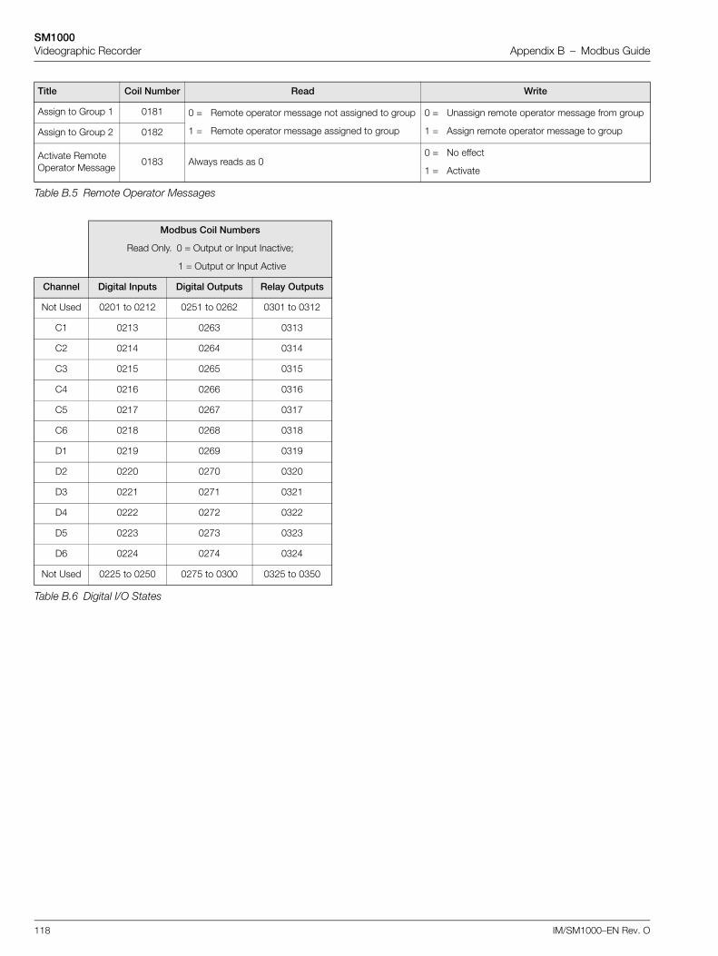
SM1000Videographic Recorder Appendix B – Modbus Guide
118 IM/SM1000–EN Rev. O
Title Coil Number Read Write
Assign to Group 1 0181 0 =
1 =
Remote operator message not assigned to group
Remote operator message assigned to group
0 =
1 =
Unassign remote operator message from group
Assign remote operator message to groupAssign to Group 2 0182
Activate Remote Operator Message
0183 Always reads as 00 =
1 =
No effect
Activate
Table B.5 Remote Operator Messages
Modbus Coil Numbers
Read Only. 0 = Output or Input Inactive;
1 = Output or Input Active
Channel Digital Inputs Digital Outputs Relay Outputs
Not Used 0201 to 0212 0251 to 0262 0301 to 0312
C1 0213 0263 0313
C2 0214 0264 0314
C3 0215 0265 0315
C4 0216 0266 0316
C5 0217 0267 0317
C6 0218 0268 0318
D1 0219 0269 0319
D2 0220 0270 0320
D3 0221 0271 0321
D4 0222 0272 0322
D5 0223 0273 0323
D6 0224 0274 0324
Not Used 0225 to 0250 0275 to 0300 0325 to 0350
Table B.6 Digital I/O States
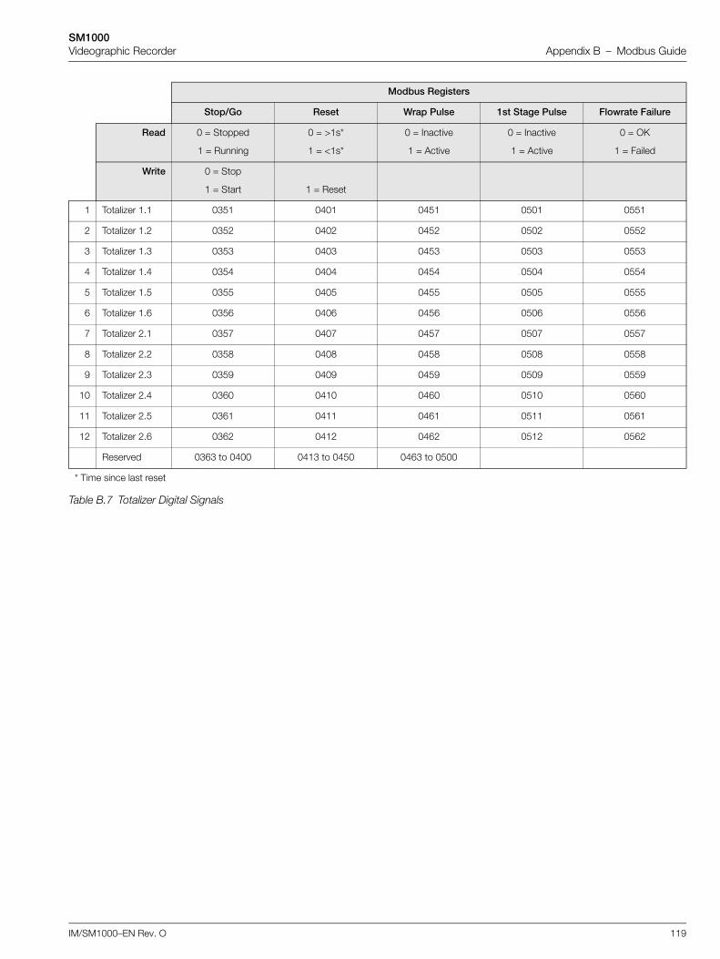
SM1000Videographic Recorder Appendix B – Modbus Guide
IM/SM1000–EN Rev. O 119
Modbus Registers
Stop/Go Reset Wrap Pulse 1st Stage Pulse Flowrate Failure
Read 0 = Stopped
1 = Running
0 = >1s*
1 = <1s*
0 = Inactive
1 = Active
0 = Inactive
1 = Active
0 = OK
1 = Failed
Write 0 = Stop
1 = Start 1 = Reset
1 Totalizer 1.1 0351 0401 0451 0501 0551
2 Totalizer 1.2 0352 0402 0452 0502 0552
3 Totalizer 1.3 0353 0403 0453 0503 0553
4 Totalizer 1.4 0354 0404 0454 0504 0554
5 Totalizer 1.5 0355 0405 0455 0505 0555
6 Totalizer 1.6 0356 0406 0456 0506 0556
7 Totalizer 2.1 0357 0407 0457 0507 0557
8 Totalizer 2.2 0358 0408 0458 0508 0558
9 Totalizer 2.3 0359 0409 0459 0509 0559
10 Totalizer 2.4 0360 0410 0460 0510 0560
11 Totalizer 2.5 0361 0411 0461 0511 0561
12 Totalizer 2.6 0362 0412 0462 0512 0562
Reserved 0363 to 0400 0413 to 0450 0463 to 0500
* Time since last reset
Table B.7 Totalizer Digital Signals
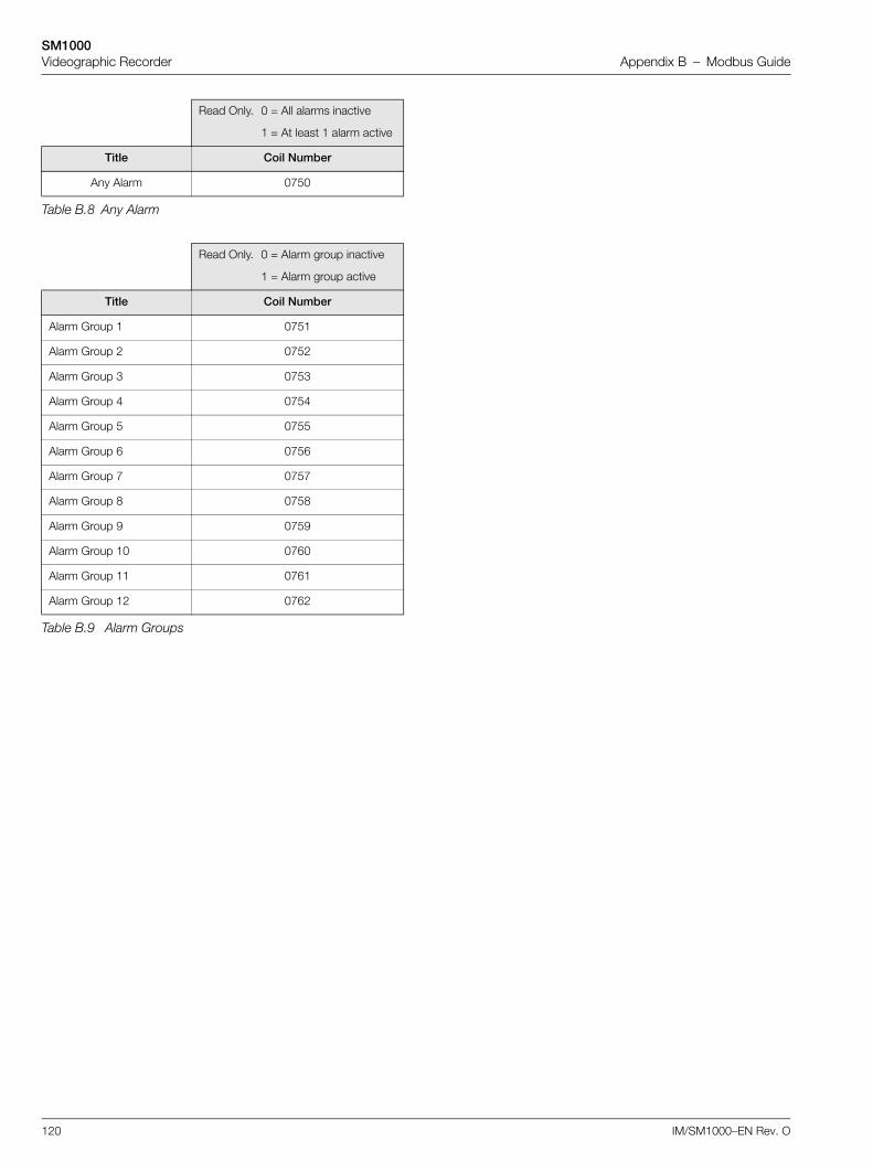
SM1000Videographic Recorder Appendix B – Modbus Guide
120 IM/SM1000–EN Rev. O
Read Only. 0 = All alarms inactive
1 = At least 1 alarm active
Title Coil Number
Any Alarm 0750
Table B.8 Any Alarm
Read Only. 0 = Alarm group inactive
1 = Alarm group active
Title Coil Number
Alarm Group 1 0751
Alarm Group 2 0752
Alarm Group 3 0753
Alarm Group 4 0754
Alarm Group 5 0755
Alarm Group 6 0756
Alarm Group 7 0757
Alarm Group 8 0758
Alarm Group 9 0759
Alarm Group 10 0760
Alarm Group 11 0761
Alarm Group 12 0762
Table B.9 Alarm Groups
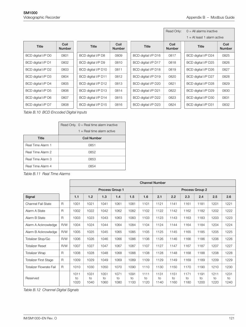
SM1000Videographic Recorder Appendix B – Modbus Guide
IM/SM1000–EN Rev. O 121
Read Only: 0 = All alarms inactive
1 = At least 1 alarm active
TitleCoil
NumberTitle
Coil Number
TitleCoil
NumberTitle
Coil Number
BCD digital I/P D0 0801 BCD digital I/P D8 0809 BCD digital I/P D16 0817 BCD digital I/P D24 0825
BCD digital I/P D1 0802 BCD digital I/P D9 0810 BCD digital I/P D17 0818 BCD digital I/P D25 0826
BCD digital I/P D2 0803 BCD digital I/P D10 0811 BCD digital I/P D18 0819 BCD digital I/P D26 0827
BCD digital I/P D3 0804 BCD digital I/P D11 0812 BCD digital I/P D19 0820 BCD digital I/P D27 0828
BCD digital I/P D4 0805 BCD digital I/P D12 0813 BCD digital I/P D20 0821 BCD digital I/P D28 0829
BCD digital I/P D5 0806 BCD digital I/P D13 0814 BCD digital I/P D21 0822 BCD digital I/P D29 0830
BCD digital I/P D6 0807 BCD digital I/P D14 0815 BCD digital I/P D22 0823 BCD digital I/P D30 0831
BCD digital I/P D7 0808 BCD digital I/P D15 0816 BCD digital I/P D23 0824 BCD digital I/P D31 0832
Table B.10 BCD Encoded Digital Inputs
Read Only. 0 = Real time alarm inactive
1 = Real time alarm active
Title Coil Number
Real Time Alarm 1 0851
Real Time Alarm 2 0852
Real Time Alarm 3 0853
Real Time Alarm 4 0854
Table B.11 Real Time Alarms
Channel Number
Process Group 1 Process Group 2
Signal 1.1 1.2 1.3 1.4 1.5 1.6 2.1 2.2 2.3 2.4 2.5 2.6
Channel Fail State R 1001 1021 1041 1061 1081 1101 1121 1141 1161 1181 1201 1221
Alarm A State R 1002 1022 1042 1062 1082 1102 1122 1142 1162 1182 1202 1222
Alarm B State R 1003 1023 1043 1063 1083 1103 1123 1143 1163 1183 1203 1223
Alarm A Acknowledge R/W 1004 1024 1044 1064 1084 1104 1124 1144 1164 1184 1204 1224
Alarm B Acknowledge R/W 1005 1025 1045 1065 1085 1105 1125 1145 1165 1185 1205 1225
Totalizer Stop/Go R/W 1006 1026 1046 1066 1086 1106 1126 1146 1166 1186 1206 1226
Totalizer Reset R/W 1007 1027 1047 1067 1087 1107 1127 1147 1167 1187 1207 1227
Totalizer Wrap R 1008 1028 1048 1068 1088 1108 1128 1148 1168 1188 1208 1228
Totalizer First Stage R 1009 1029 1049 1069 1089 1109 1129 1149 1169 1189 1209 1229
Totalizer Flowrate Fail R 1010 1030 1050 1070 1090 1110 1130 1150 1170 1190 1210 1230
Reserved1011
to 1020
1031 to
1040
1051 to
1060
1071 to
1080
1091 to
1100
1111 to
1120
1131 to
1140
1151 to
1160
1171 to
1180
1191 to
1200
1211 to
1220
1231 to
1240
Table B.12 Channel Digital Signals
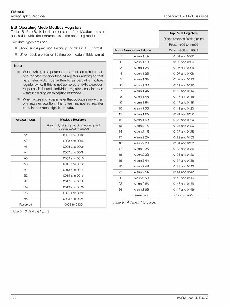
SM1000Videographic Recorder Appendix B – Modbus Guide
122 IM/SM1000–EN Rev. O
B.6 Operating Mode Modbus RegistersTables B.13 to B.19 detail the contents of the Modbus registersaccessible while the instrument is in the operating mode.
Two data types are used:
32-bit single precision floating point data in IEEE format
64-bit double precision floating point data in IEEE format
Note.
When writing to a parameter that occupies more thanone register position then all registers relating to thatparameter MUST be written to as part of a multipleregister write. If this is not achieved a NAK exceptionresponse is issued. Individual registers can be readwithout causing an exception response.
When accessing a parameter that occupies more thanone register position, the lowest numbered registercontains the most significant data.
Analog Inputs Modbus Registers
Read only, single precision floating point number –999 to +9999
A1 0001 and 0002
A2 0003 and 0004
A3 0005 and 0006
A4 0007 and 0008
A5 0009 and 0010
A6 0011 and 0012
B1 0013 and 0014
B2 0015 and 0016
B3 0017 and 0018
B4 0019 and 0020
B5 0021 and 0022
B6 0023 and 0024
Reserved 0025 to 0100
Table B.13 Analog Inputs
Trip Point Registers
(single precision floating point)
Read: –999 to +9999
Alarm Number and Name Write: –999 to +9999
1 Alarm 1.1A 0101 and 0102
2 Alarm 1.1B 0103 and 0104
3 Alarm 1.2A 0105 and 0106
4 Alarm 1.2B 0107 and 0108
5 Alarm 1.3A 0109 and 0110
6 Alarm 1.3B 0111 and 0112
7 Alarm 1.4A 0113 and 0114
8 Alarm 1.4B 0115 and 0116
9 Alarm 1.5A 0117 and 0118
10 Alarm 1.5B 0119 and 0120
11 Alarm 1.6A 0121 and 0122
12 Alarm 1.6B 0123 and 0124
13 Alarm 2.1A 0125 and 0126
14 Alarm 2.1B 0127 and 0128
15 Alarm 2.2A 0129 and 0130
16 Alarm 2.2B 0131 and 0132
17 Alarm 2.3A 0133 and 0134
18 Alarm 2.3B 0135 and 0136
19 Alarm 2.4A 0137 and 0138
20 Alarm 2.4B 0139 and 0140
21 Alarm 2.5A 0141 and 0142
22 Alarm 2.5B 0143 and 0144
23 Alarm 2.6A 0145 and 0146
24 Alarm 2.6B 0147 and 0148
Reserved 0149 to 0250
Table B.14 Alarm Trip Levels
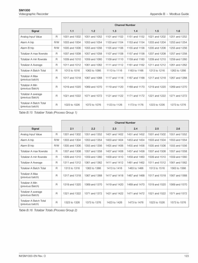
SM1000Videographic Recorder Appendix B – Modbus Guide
IM/SM1000–EN Rev. O 123
Channel Number
Signal 1.1 1.2 1.3 1.4 1.5 1.6
Analog Input Value R 1001 and 1002 1051 and 1052 1101 and 1102 1151 and 1152 1021 and 1202 1251 and 1252
Alarm A trip R/W 1003 and 1004 1053 and 1054 1103 and 1104 1153 and 1154 1203 and 1204 1253 and 1254
Alarm B trip R/W 1005 and 1006 1055 and 1056 1105 and 1106 1155 and 1156 1205 and 1206 1255 and 1256
Totalizer A max flowrate R 1007 and 1008 1057 and 1058 1107 and 1108 1157 and 1158 1207 and 1208 1257 and 1258
Totalizer A min flowrate R 1009 and 1010 1059 and 1060 1109 and 1110 1159 and 1160 1209 and 1210 1259 and 1260
Totalizer A Average R 1011 and 1012 1061 and 1062 1111 and 1112 1161 and 1162 1211 and 1212 1261 and 1262
Totalizer A Batch Total R 1013 to 1016 1063 to 1066 1113 to 1116 1163 to 1166 1213 to 1216 1263 to 1266
Totalizer A Max (previous batch)
R 1017 and 1018 1067 and 1068 1117 and 1118 1167 and 1168 1217 and 1218 1267 and 1268
Totalizer A Min (previous Batch)
R 1019 and 1020 1069 and 1070 1119 and 1120 1169 and 1170 1219 and 1220 1269 and 1270
Totalizer A average (previous Batch)
R 1021 and 1022 1071 and 1072 1121 and 1122 1171 and 1172 1221 and 1222 1271 and 1272
Totalizer A Batch Total (previous batch)
R 1023 to 1026 1073 to 1076 1123 to 1126 1173 to 1176 1223 to 1226 1273 to 1276
Table B.15 Totalizer Totals (Process Group 1)
Channel Number
Signal 2.1 2.2 2.3 2.4 2.5 2.6
Analog Input Value R 1301 and 1302 1351 and 1352 1401 and 1402 1451 and 1452 1501 and 1502 1551 and 1552
Alarm A trip R/W 1303 and 1304 1353 and 1354 1403 and 1404 1453 and 1454 1503 and 1504 1553 and 1554
Alarm B trip R/W 1305 and 1306 1355 and 1356 1405 and 1406 1455 and 1456 1505 and 1506 1555 and 1556
Totalizer A max flowrate R 1307 and 1308 1357 and 1358 1407 and 1408 1457 and 1458 1507 and 1508 1557 and 1558
Totalizer A min flowrate R 1309 and 1310 1359 and 1360 1409 and 1410 1459 and 1460 1509 and 1510 1559 and 1560
Totalizer A Average R 1311 and 1312 1361 and 1362 1411 and 1412 1461 and 1462 1511 and 1512 1561 and 1562
Totalizer A Batch Total R 1313 to 1316 1363 to 1366 1413 to 1416 1463 to 1466 1513 to 1516 1563 to 1566
Totalizer A Max (previous batch)
R 1317 and 1318 1367 and 1368 1417 and 1418 1467 and 1468 1517 and 1518 1567 and 1568
Totalizer A Min (previous Batch)
R 1319 and 1320 1369 and 1370 1419 and 1420 1469 and 1470 1519 and 1520 1569 and 1570
Totalizer A average (previous Batch)
R 1321 and 1322 1371 and 1372 1421 and 1422 1471 and 1472 1521 and 1522 1571 and 1572
Totalizer A Batch Total (previous batch)
R 1323 to 1326 1373 to 1376 1423 to 1426 1473 to 1476 1523 to 1526 1573 to 1576
Table B.16 Totalizer Totals (Process Group 2)
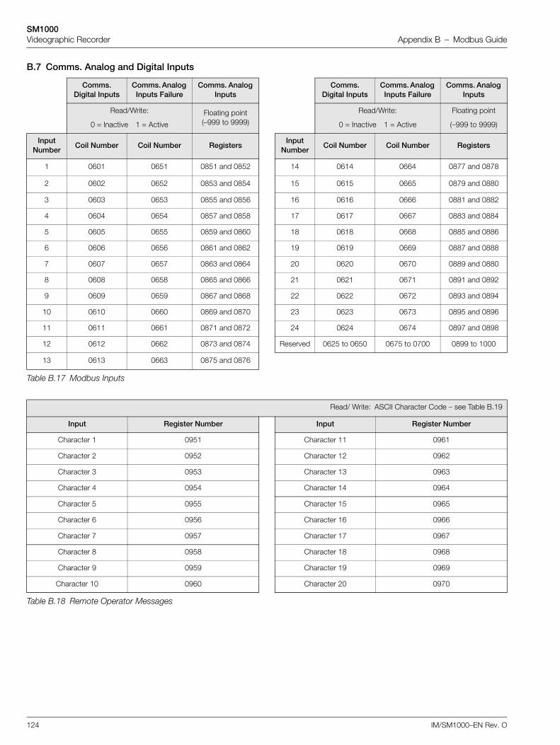
SM1000Videographic Recorder Appendix B – Modbus Guide
124 IM/SM1000–EN Rev. O
B.7 Comms. Analog and Digital Inputs
Comms. Digital Inputs
Comms. Analog Inputs Failure
Comms. Analog Inputs
Comms. Digital Inputs
Comms. Analog Inputs Failure
Comms. Analog Inputs
Read/Write:
0 = Inactive 1 = Active
Floating point(–999 to 9999)
Read/Write:
0 = Inactive 1 = Active
Floating point
(–999 to 9999)
Input Number
Coil Number Coil Number RegistersInput
NumberCoil Number Coil Number Registers
1 0601 0651 0851 and 0852 14 0614 0664 0877 and 0878
2 0602 0652 0853 and 0854 15 0615 0665 0879 and 0880
3 0603 0653 0855 and 0856 16 0616 0666 0881 and 0882
4 0604 0654 0857 and 0858 17 0617 0667 0883 and 0884
5 0605 0655 0859 and 0860 18 0618 0668 0885 and 0886
6 0606 0656 0861 and 0862 19 0619 0669 0887 and 0888
7 0607 0657 0863 and 0864 20 0620 0670 0889 and 0880
8 0608 0658 0865 and 0866 21 0621 0671 0891 and 0892
9 0609 0659 0867 and 0868 22 0622 0672 0893 and 0894
10 0610 0660 0869 and 0870 23 0623 0673 0895 and 0896
11 0611 0661 0871 and 0872 24 0624 0674 0897 and 0898
12 0612 0662 0873 and 0874 Reserved 0625 to 0650 0675 to 0700 0899 to 1000
13 0613 0663 0875 and 0876
Table B.17 Modbus Inputs
Read/ Write: ASCII Character Code – see Table B.19
Input Register Number Input Register Number
Character 1 0951 Character 11 0961
Character 2 0952 Character 12 0962
Character 3 0953 Character 13 0963
Character 4 0954 Character 14 0964
Character 5 0955 Character 15 0965
Character 6 0956 Character 16 0966
Character 7 0957 Character 17 0967
Character 8 0958 Character 18 0968
Character 9 0959 Character 19 0969
Character 10 0960 Character 20 0970
Table B.18 Remote Operator Messages
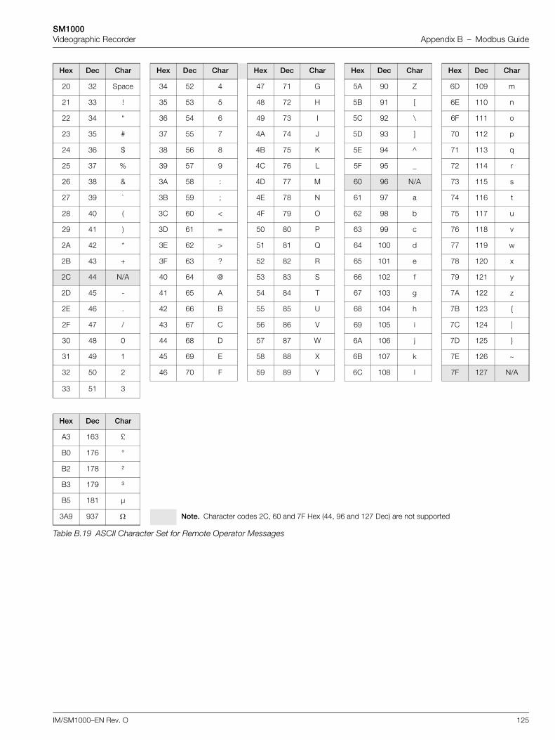
SM1000Videographic Recorder Appendix B – Modbus Guide
IM/SM1000–EN Rev. O 125
Hex Dec Char Hex Dec Char Hex Dec Char Hex Dec Char Hex Dec Char
20 32 Space 34 52 4 47 71 G 5A 90 Z 6D 109 m
21 33 ! 35 53 5 48 72 H 5B 91 [ 6E 110 n
22 34 “ 36 54 6 49 73 I 5C 92 \ 6F 111 o
23 35 # 37 55 7 4A 74 J 5D 93 ] 70 112 p
24 36 $ 38 56 8 4B 75 K 5E 94 ^ 71 113 q
25 37 % 39 57 9 4C 76 L 5F 95 _ 72 114 r
26 38 & 3A 58 : 4D 77 M 60 96 N/A 73 115 s
27 39 ` 3B 59 ; 4E 78 N 61 97 a 74 116 t
28 40 ( 3C 60 < 4F 79 O 62 98 b 75 117 u
29 41 ) 3D 61 = 50 80 P 63 99 c 76 118 v
2A 42 * 3E 62 > 51 81 Q 64 100 d 77 119 w
2B 43 + 3F 63 ? 52 82 R 65 101 e 78 120 x
2C 44 N/A 40 64 @ 53 83 S 66 102 f 79 121 y
2D 45 - 41 65 A 54 84 T 67 103 g 7A 122 z
2E 46 . 42 66 B 55 85 U 68 104 h 7B 123 {
2F 47 / 43 67 C 56 86 V 69 105 i 7C 124 |
30 48 0 44 68 D 57 87 W 6A 106 j 7D 125 }
31 49 1 45 69 E 58 88 X 6B 107 k 7E 126 ~
32 50 2 46 70 F 59 89 Y 6C 108 l 7F 127 N/A
33 51 3
Hex Dec Char
A3 163 £
B0 176 °
B2 178 ²
B3 179 ³
B5 181 µ
3A9 937 Note. Character codes 2C, 60 and 7F Hex (44, 96 and 127 Dec) are not supported
Table B.19 ASCII Character Set for Remote Operator Messages
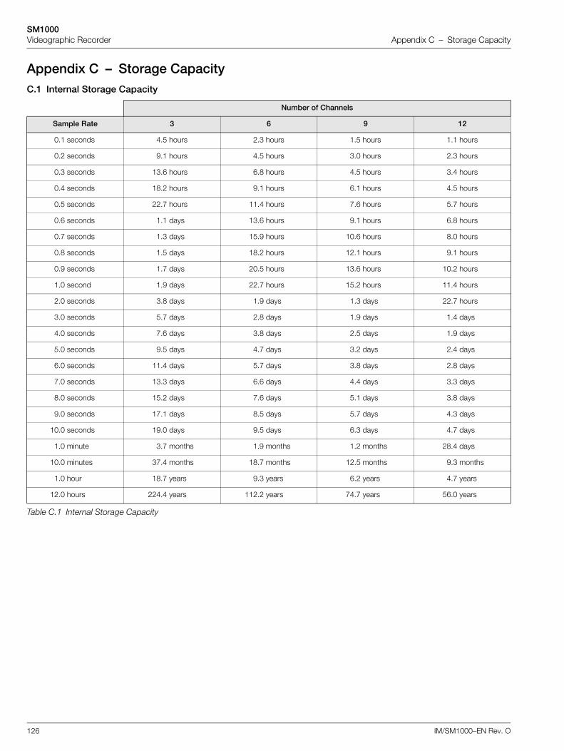
SM1000Videographic Recorder Appendix C – Storage Capacity
126 IM/SM1000–EN Rev. O
Appendix C – Storage CapacityC.1 Internal Storage Capacity
Number of Channels
Sample Rate 3 6 9 12
0.1 seconds 4.5 hours 2.3 hours 1.5 hours 1.1 hours
0.2 seconds 9.1 hours 4.5 hours 3.0 hours 2.3 hours
0.3 seconds 13.6 hours 6.8 hours 4.5 hours 3.4 hours
0.4 seconds 18.2 hours 9.1 hours 6.1 hours 4.5 hours
0.5 seconds 22.7 hours 11.4 hours 7.6 hours 5.7 hours
0.6 seconds 1.1 days 13.6 hours 9.1 hours 6.8 hours
0.7 seconds 1.3 days 15.9 hours 10.6 hours 8.0 hours
0.8 seconds 1.5 days 18.2 hours 12.1 hours 9.1 hours
0.9 seconds 1.7 days 20.5 hours 13.6 hours 10.2 hours
1.0 second 1.9 days 22.7 hours 15.2 hours 11.4 hours
2.0 seconds 3.8 days 1.9 days 1.3 days 22.7 hours
3.0 seconds 5.7 days 2.8 days 1.9 days 1.4 days
4.0 seconds 7.6 days 3.8 days 2.5 days 1.9 days
5.0 seconds 9.5 days 4.7 days 3.2 days 2.4 days
6.0 seconds 11.4 days 5.7 days 3.8 days 2.8 days
7.0 seconds 13.3 days 6.6 days 4.4 days 3.3 days
8.0 seconds 15.2 days 7.6 days 5.1 days 3.8 days
9.0 seconds 17.1 days 8.5 days 5.7 days 4.3 days
10.0 seconds 19.0 days 9.5 days 6.3 days 4.7 days
1.0 minute 3.7 months 1.9 months 1.2 months 28.4 days
10.0 minutes 37.4 months 18.7 months 12.5 months 9.3 months
1.0 hour 18.7 years 9.3 years 6.2 years 4.7 years
12.0 hours 224.4 years 112.2 years 74.7 years 56.0 years
Table C.1 Internal Storage Capacity
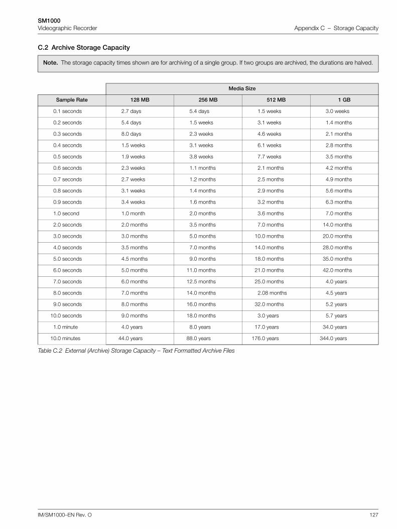
SM1000Videographic Recorder Appendix C – Storage Capacity
IM/SM1000–EN Rev. O 127
C.2 Archive Storage Capacity
Note. The storage capacity times shown are for archiving of a single group. If two groups are archived, the durations are halved.
Media Size
Sample Rate 128 MB 256 MB 512 MB 1 GB
0.1 seconds 2.7 days 5.4 days 1.5 weeks 3.0 weeks
0.2 seconds 5.4 days 1.5 weeks 3.1 weeks 1.4 months
0.3 seconds 8.0 days 2.3 weeks 4.6 weeks 2.1 months
0.4 seconds 1.5 weeks 3.1 weeks 6.1 weeks 2.8 months
0.5 seconds 1.9 weeks 3.8 weeks 7.7 weeks 3.5 months
0.6 seconds 2.3 weeks 1.1 months 2.1 months 4.2 months
0.7 seconds 2.7 weeks 1.2 months 2.5 months 4.9 months
0.8 seconds 3.1 weeks 1.4 months 2.9 months 5.6 months
0.9 seconds 3.4 weeks 1.6 months 3.2 months 6.3 months
1.0 second 1.0 month 2.0 months 3.6 months 7.0 months
2.0 seconds 2.0 months 3.5 months 7.0 months 14.0 months
3.0 seconds 3.0 months 5.0 months 10.0 months 20.0 months
4.0 seconds 3.5 months 7.0 months 14.0 months 28.0 months
5.0 seconds 4.5 months 9.0 months 18.0 months 35.0 months
6.0 seconds 5.0 months 11.0 months 21.0 months 42.0 months
7.0 seconds 6.0 months 12.5 months 25.0 months 4.0 years
8.0 seconds 7.0 months 14.0 months 2.08 months 4.5 years
9.0 seconds 8.0 months 16.0 months 32.0 months 5.2 years
10.0 seconds 9.0 months 18.0 months 3.0 years 5.7 years
1.0 minute 4.0 years 8.0 years 17.0 years 34.0 years
10.0 minutes 44.0 years 88.0 years 176.0 years 344.0 years
Table C.2 External (Archive) Storage Capacity – Text Formatted Archive Files
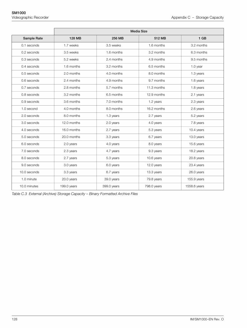
SM1000Videographic Recorder Appendix C – Storage Capacity
128 IM/SM1000–EN Rev. O
Media Size
Sample Rate 128 MB 256 MB 512 MB 1 GB
0.1 seconds 1.7 weeks 3.5 weeks 1.6 months 3.2 months
0.2 seconds 3.5 weeks 1.6 months 3.2 months 6.3 months
0.3 seconds 5.2 weeks 2.4 months 4.9 months 9.5 months
0.4 seconds 1.6 months 3.2 months 6.5 months 1.0 year
0.5 seconds 2.0 months 4.0 months 8.0 months 1.3 years
0.6 seconds 2.4 months 4.9 months 9.7 months 1.6 years
0.7 seconds 2.8 months 5.7 months 11.3 months 1.8 years
0.8 seconds 3.2 months 6.5 months 12.9 months 2.1 years
0.9 seconds 3.6 months 7.0 months 1.2 years 2.3 years
1.0 second 4.0 months 8.0 months 16.2 months 2.6 years
2.0 seconds 8.0 months 1.3 years 2.7 years 5.2 years
3.0 seconds 12.0 months 2.0 years 4.0 years 7.8 years
4.0 seconds 16.0 months 2.7 years 5.3 years 10.4 years
5.0 seconds 20.0 months 3.3 years 6.7 years 13.0 years
6.0 seconds 2.0 years 4.0 years 8.0 years 15.6 years
7.0 seconds 2.3 years 4.7 years 9.3 years 18.2 years
8.0 seconds 2.7 years 5.3 years 10.6 years 20.8 years
9.0 seconds 3.0 years 6.0 years 12.0 years 23.4 years
10.0 seconds 3.3 years 6.7 years 13.3 years 26.0 years
1.0 minute 20.0 years 39.0 years 79.8 years 155.9 years
10.0 minutes 199.0 years 399.0 years 798.0 years 1558.6 years
Table C.3 External (Archive) Storage Capacity – Binary Formatted Archive Files
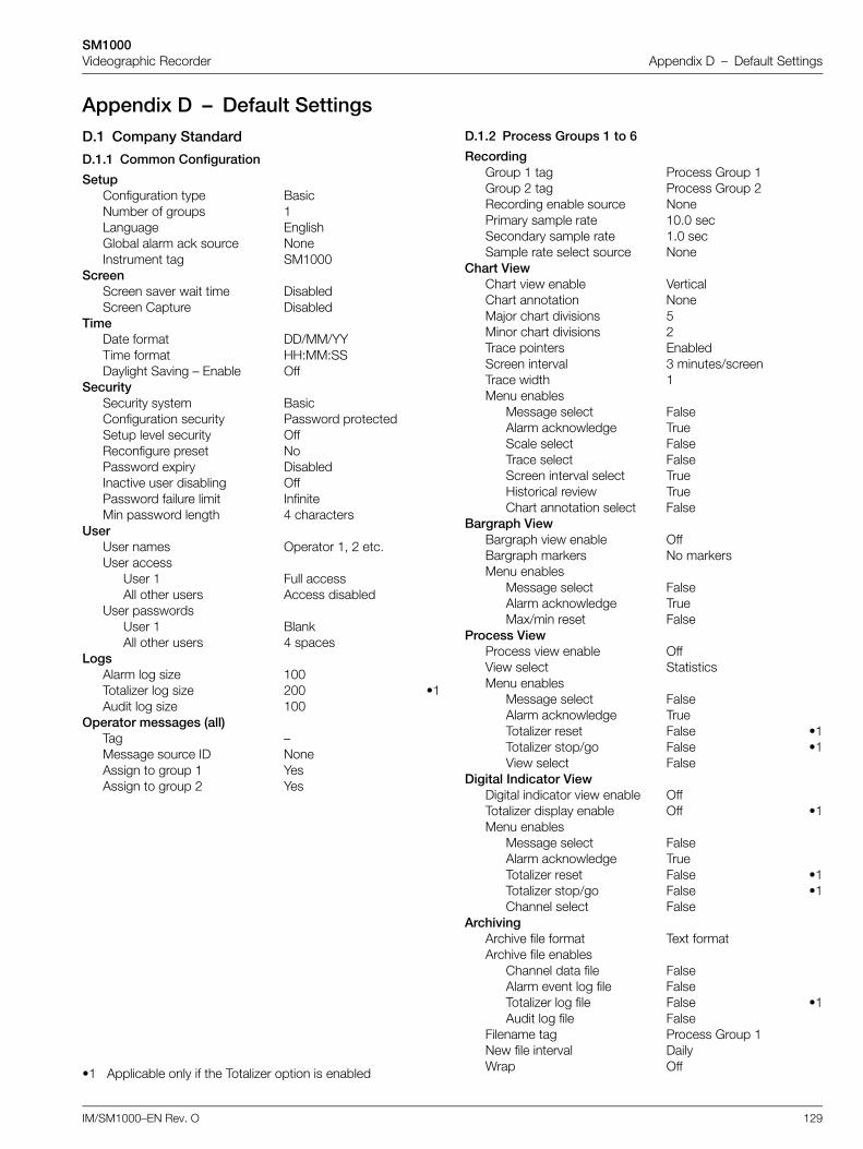
SM1000Videographic Recorder Appendix D – Default Settings
IM/SM1000–EN Rev. O 129
Appendix D – Default SettingsD.1 Company Standard
D.1.1 Common Configuration
D.1.2 Process Groups 1 to 6
SetupConfiguration type BasicNumber of groups 1Language EnglishGlobal alarm ack source NoneInstrument tag SM1000
ScreenScreen saver wait time DisabledScreen Capture Disabled
TimeDate format DD/MM/YYTime format HH:MM:SSDaylight Saving – Enable Off
SecuritySecurity system BasicConfiguration security Password protectedSetup level security OffReconfigure preset NoPassword expiry DisabledInactive user disabling OffPassword failure limit InfiniteMin password length 4 characters
UserUser names Operator 1, 2 etc.User access
User 1 Full accessAll other users Access disabled
User passwordsUser 1 BlankAll other users 4 spaces
LogsAlarm log size 100Totalizer log size 200 •1Audit log size 100
Operator messages (all)Tag –Message source ID NoneAssign to group 1 YesAssign to group 2 Yes
•1 Applicable only if the Totalizer option is enabled
RecordingGroup 1 tag Process Group 1Group 2 tag Process Group 2Recording enable source NonePrimary sample rate 10.0 secSecondary sample rate 1.0 secSample rate select source None
Chart ViewChart view enable VerticalChart annotation NoneMajor chart divisions 5Minor chart divisions 2Trace pointers EnabledScreen interval 3 minutes/screenTrace width 1Menu enables
Message select FalseAlarm acknowledge TrueScale select FalseTrace select FalseScreen interval select TrueHistorical review TrueChart annotation select False
Bargraph ViewBargraph view enable OffBargraph markers No markersMenu enables
Message select FalseAlarm acknowledge TrueMax/min reset False
Process ViewProcess view enable OffView select StatisticsMenu enables
Message select FalseAlarm acknowledge TrueTotalizer reset False •1Totalizer stop/go False •1View select False
Digital Indicator ViewDigital indicator view enable OffTotalizer display enable Off •1Menu enables
Message select FalseAlarm acknowledge TrueTotalizer reset False •1Totalizer stop/go False •1Channel select False
ArchivingArchive file format Text formatArchive file enables
Channel data file FalseAlarm event log file FalseTotalizer log file False •1Audit log file False
Filename tag Process Group 1New file interval DailyWrap Off
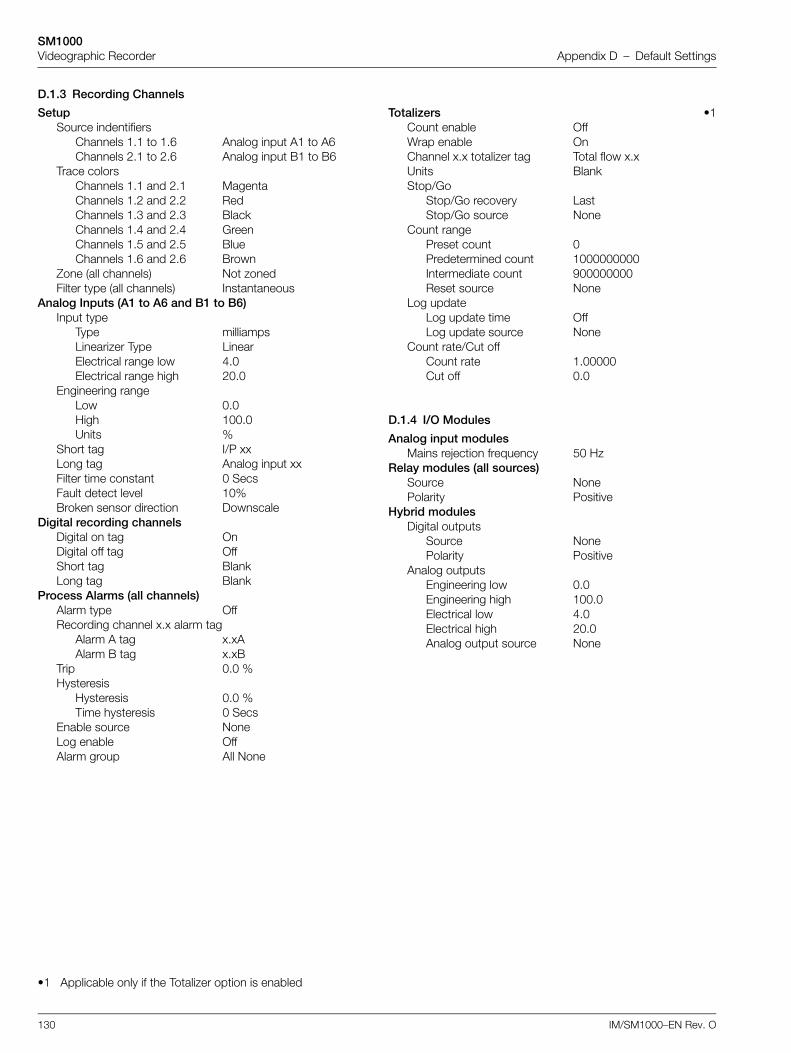
SM1000Videographic Recorder Appendix D – Default Settings
130 IM/SM1000–EN Rev. O
D.1.3 Recording Channels
D.1.4 I/O Modules
SetupSource indentifiers
Channels 1.1 to 1.6 Analog input A1 to A6Channels 2.1 to 2.6 Analog input B1 to B6
Trace colorsChannels 1.1 and 2.1 MagentaChannels 1.2 and 2.2 RedChannels 1.3 and 2.3 BlackChannels 1.4 and 2.4 GreenChannels 1.5 and 2.5 BlueChannels 1.6 and 2.6 Brown
Zone (all channels) Not zonedFilter type (all channels) Instantaneous
Analog Inputs (A1 to A6 and B1 to B6)Input type
Type milliampsLinearizer Type LinearElectrical range low 4.0Electrical range high 20.0
Engineering rangeLow 0.0High 100.0Units %
Short tag I/P xxLong tag Analog input xxFilter time constant 0 SecsFault detect level 10%Broken sensor direction Downscale
Digital recording channelsDigital on tag OnDigital off tag OffShort tag BlankLong tag Blank
Process Alarms (all channels)Alarm type OffRecording channel x.x alarm tag
Alarm A tag x.xAAlarm B tag x.xB
Trip 0.0 %Hysteresis
Hysteresis 0.0 %Time hysteresis 0 Secs
Enable source NoneLog enable OffAlarm group All None
•1 Applicable only if the Totalizer option is enabled
Totalizers •1Count enable OffWrap enable OnChannel x.x totalizer tag Total flow x.xUnits BlankStop/Go
Stop/Go recovery LastStop/Go source None
Count rangePreset count 0Predetermined count 1000000000Intermediate count 900000000Reset source None
Log updateLog update time OffLog update source None
Count rate/Cut offCount rate 1.00000Cut off 0.0
Analog input modulesMains rejection frequency 50 Hz
Relay modules (all sources)Source NonePolarity Positive
Hybrid modulesDigital outputs
Source NonePolarity Positive
Analog outputsEngineering low 0.0Engineering high 100.0Electrical low 4.0Electrical high 20.0Analog output source None
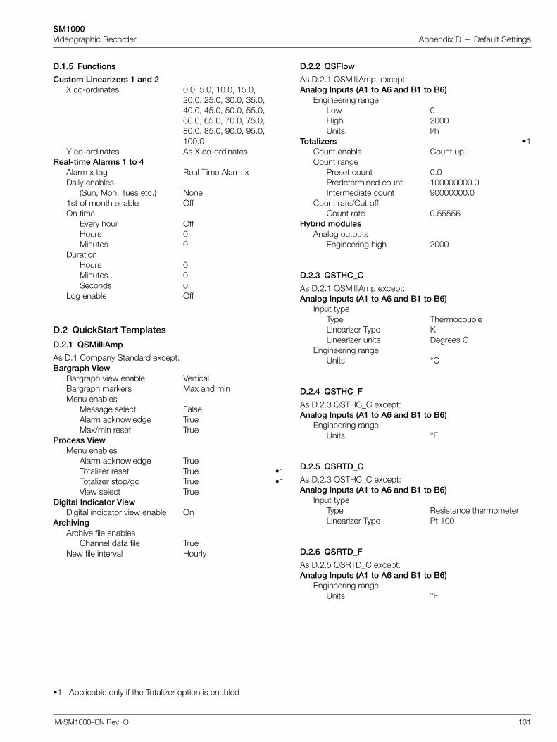
SM1000Videographic Recorder Appendix D – Default Settings
IM/SM1000–EN Rev. O 131
D.1.5 Functions
D.2 QuickStart Templates
D.2.1 QSMilliAmp
D.2.2 QSFlow
D.2.3 QSTHC_C
D.2.4 QSTHC_F
D.2.5 QSRTD_C
D.2.6 QSRTD_F
Custom Linearizers 1 and 2X co-ordinates 0.0, 5.0, 10.0, 15.0,
20.0, 25.0, 30.0, 35.0, 40.0, 45.0, 50.0, 55.0, 60.0, 65.0, 70.0, 75.0, 80.0, 85.0, 90.0, 95.0, 100.0
Y co-ordinates As X co-ordinatesReal-time Alarms 1 to 4
Alarm x tag Real Time Alarm xDaily enables
(Sun, Mon, Tues etc.) None1st of month enable OffOn time
Every hour OffHours 0Minutes 0
DurationHours 0Minutes 0Seconds 0
Log enable Off
As D.1 Company Standard except:Bargraph View
Bargraph view enable VerticalBargraph markers Max and minMenu enables
Message select FalseAlarm acknowledge TrueMax/min reset True
Process ViewMenu enables
Alarm acknowledge TrueTotalizer reset True •1Totalizer stop/go True •1View select True
Digital Indicator ViewDigital indicator view enable On
ArchivingArchive file enables
Channel data file TrueNew file interval Hourly
•1 Applicable only if the Totalizer option is enabled
As D.2.1 QSMilliAmp, except:Analog Inputs (A1 to A6 and B1 to B6)
Engineering rangeLow 0High 2000Units l/h
Totalizers •1Count enable Count upCount range
Preset count 0.0Predetermined count 100000000.0Intermediate count 90000000.0
Count rate/Cut offCount rate 0.55556
Hybrid modulesAnalog outputs
Engineering high 2000
As D.2.1 QSMilliAmp except:Analog Inputs (A1 to A6 and B1 to B6)
Input typeType ThermocoupleLinearizer Type KLinearizer units Degrees C
Engineering rangeUnits °C
As D.2.3 QSTHC_C except:Analog Inputs (A1 to A6 and B1 to B6)
Engineering rangeUnits °F
As D.2.3 QSTHC_C except: Analog Inputs (A1 to A6 and B1 to B6)
Input typeType Resistance thermometerLinearizer Type Pt 100
As D.2.5 QSRTD_C except:Analog Inputs (A1 to A6 and B1 to B6)
Engineering rangeUnits °F
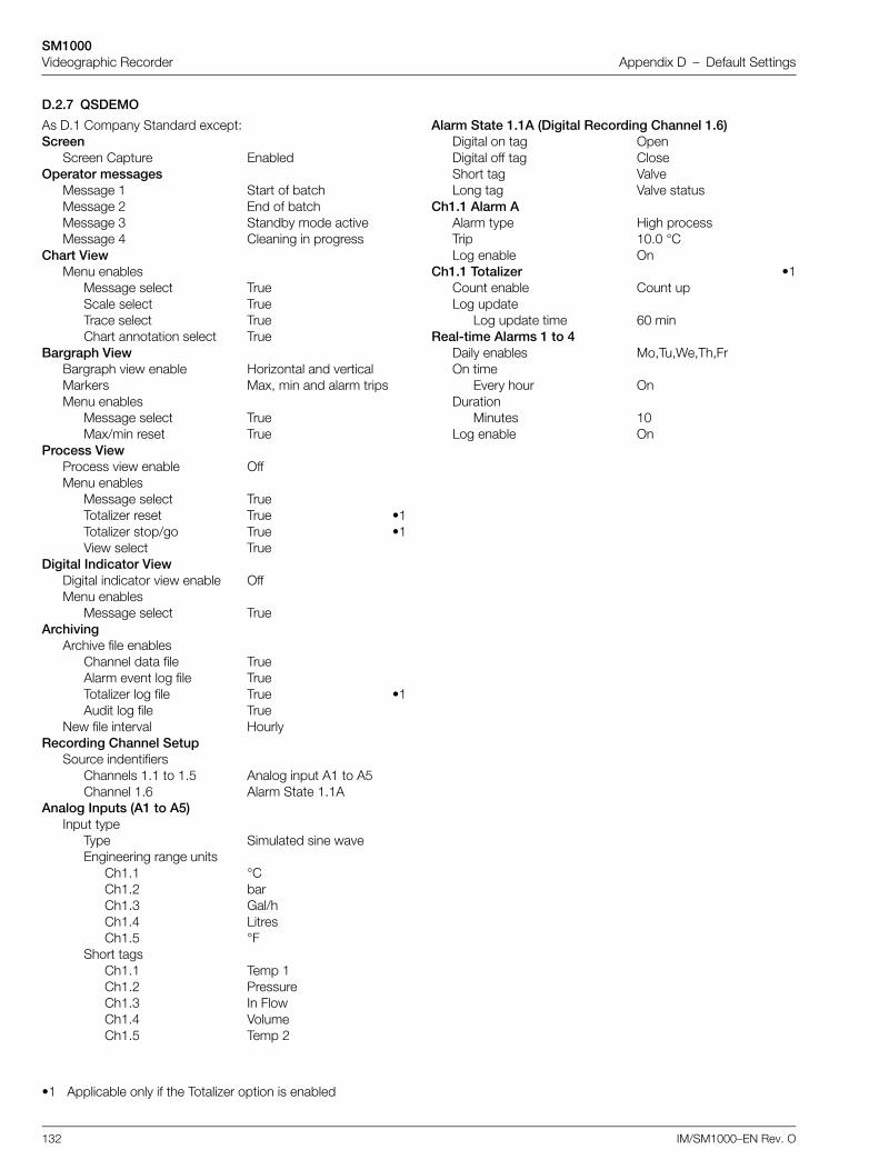
SM1000Videographic Recorder Appendix D – Default Settings
132 IM/SM1000–EN Rev. O
D.2.7 QSDEMO
As D.1 Company Standard except:Screen
Screen Capture EnabledOperator messages
Message 1 Start of batchMessage 2 End of batchMessage 3 Standby mode activeMessage 4 Cleaning in progress
Chart ViewMenu enables
Message select TrueScale select TrueTrace select TrueChart annotation select True
Bargraph ViewBargraph view enable Horizontal and verticalMarkers Max, min and alarm tripsMenu enables
Message select TrueMax/min reset True
Process ViewProcess view enable OffMenu enables
Message select TrueTotalizer reset True •1Totalizer stop/go True •1View select True
Digital Indicator ViewDigital indicator view enable OffMenu enables
Message select TrueArchiving
Archive file enablesChannel data file TrueAlarm event log file TrueTotalizer log file True •1Audit log file True
New file interval HourlyRecording Channel Setup
Source indentifiersChannels 1.1 to 1.5 Analog input A1 to A5Channel 1.6 Alarm State 1.1A
Analog Inputs (A1 to A5)Input type
Type Simulated sine waveEngineering range units
Ch1.1 °CCh1.2 barCh1.3 Gal/hCh1.4 LitresCh1.5 °F
Short tagsCh1.1 Temp 1Ch1.2 PressureCh1.3 In FlowCh1.4 VolumeCh1.5 Temp 2
•1 Applicable only if the Totalizer option is enabled
Alarm State 1.1A (Digital Recording Channel 1.6)Digital on tag OpenDigital off tag CloseShort tag ValveLong tag Valve status
Ch1.1 Alarm AAlarm type High processTrip 10.0 °CLog enable On
Ch1.1 Totalizer •1Count enable Count upLog update
Log update time 60 minReal-time Alarms 1 to 4
Daily enables Mo,Tu,We,Th,FrOn time
Every hour OnDuration
Minutes 10Log enable On
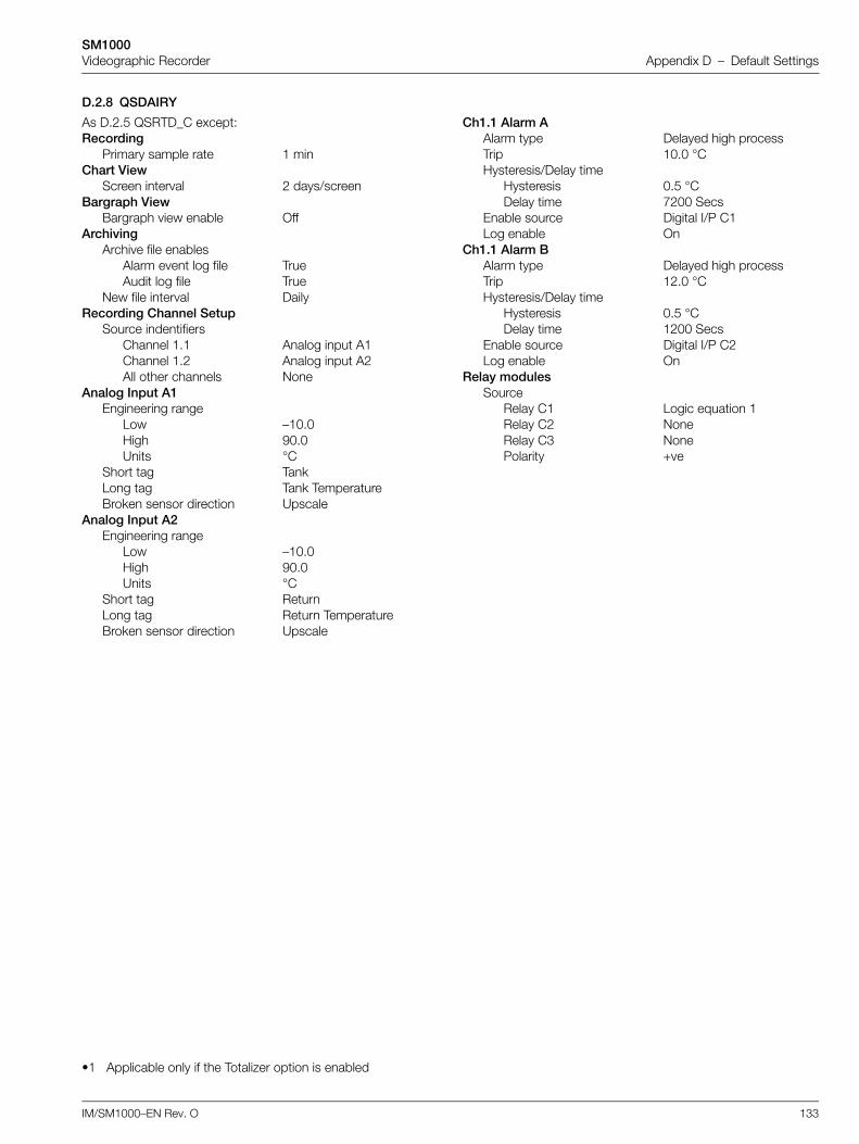
SM1000Videographic Recorder Appendix D – Default Settings
IM/SM1000–EN Rev. O 133
D.2.8 QSDAIRY
As D.2.5 QSRTD_C except:Recording
Primary sample rate 1 minChart View
Screen interval 2 days/screenBargraph View
Bargraph view enable OffArchiving
Archive file enablesAlarm event log file TrueAudit log file True
New file interval DailyRecording Channel Setup
Source indentifiersChannel 1.1 Analog input A1Channel 1.2 Analog input A2All other channels None
Analog Input A1Engineering range
Low –10.0High 90.0Units °C
Short tag TankLong tag Tank TemperatureBroken sensor direction Upscale
Analog Input A2Engineering range
Low –10.0High 90.0Units °C
Short tag ReturnLong tag Return TemperatureBroken sensor direction Upscale
•1 Applicable only if the Totalizer option is enabled
Ch1.1 Alarm AAlarm type Delayed high processTrip 10.0 °CHysteresis/Delay time
Hysteresis 0.5 °CDelay time 7200 Secs
Enable source Digital I/P C1Log enable On
Ch1.1 Alarm BAlarm type Delayed high processTrip 12.0 °CHysteresis/Delay time
Hysteresis 0.5 °CDelay time 1200 Secs
Enable source Digital I/P C2Log enable On
Relay modulesSource
Relay C1 Logic equation 1Relay C2 NoneRelay C3 NonePolarity +ve
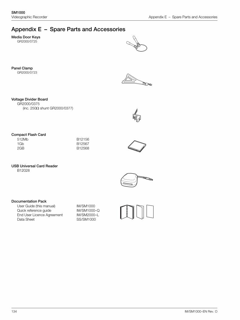
SM1000Videographic Recorder Appendix E – Spare Parts and Accessories
134 IM/SM1000–EN Rev. O
Appendix E – Spare Parts and AccessoriesMedia Door Keys
GR2000/0725
Panel ClampGR2000/0723
Voltage Divider BoardGR2000/0375
(inc. 250 shunt GR2000/0377)
Compact Flash Card512Mb B121561Gb B125672GB B12568
USB Universal Card ReaderB12028
Documentation PackUser Guide (this manual) IM/SM1000Quick reference guide IM/SM1000–QEnd User Licence Agreement IM/SM2000–LData Sheet SS/SM1000
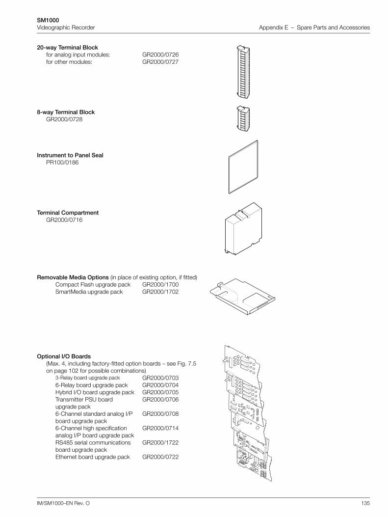
SM1000Videographic Recorder Appendix E – Spare Parts and Accessories
IM/SM1000–EN Rev. O 135
20-way Terminal Blockfor analog input modules: GR2000/0726for other modules: GR2000/0727
8-way Terminal BlockGR2000/0728
Instrument to Panel SealPR100/0186
Terminal CompartmentGR2000/0716
Removable Media Options (in place of existing option, if fitted)Compact Flash upgrade pack GR2000/1700SmartMedia upgrade pack GR2000/1702
Optional I/O Boards(Max. 4, including factory-fitted option boards – see Fig. 7.5 on page 102 for possible combinations)
3-Relay board upgrade pack GR2000/07036-Relay board upgrade pack GR2000/0704Hybrid I/O board upgrade pack GR2000/0705Transmitter PSU board upgrade pack
GR2000/0706
6-Channel standard analog I/P board upgrade pack
GR2000/0708
6-Channel high specification analog I/P board upgrade pack
GR2000/0714
RS485 serial communications board upgrade pack
GR2000/1722
Ethernet board upgrade pack GR2000/0722

SM1000Videographic Recorder Appendix F – Error & Diagnostics Information
136 IM/SM1000–EN Rev. O
Appendix F – Error & Diagnostics InformationError Message Action
"The system has not finished updating the files in the storage cardfolder. Please re-insert the storage card now. WARNING: Failure to doso may result in lost data on the storage card."
Re-insert the storage card immediately and press the key to clearthe error message.
"Would you like the system to format the storage card folder so that thesystem can use it? WARNING: If you select Yes, all files on the storagecard folder will be erased!".
Remove the card from the recorder and format the card on a PC beforereinserting.
"Disk removed before signature sign" message appears in audit log. Caused by static damage to media card. Format or replace currentcard. Observe anti-static precautions when handling.

SM1000Videographic Recorder Appendix G – Symbols and Icons
IM/SM1000–EN Rev. O 137
Appendix G – Symbols and Icons
Status Icons
Historical Review Active
External archive media on-line (green icon, shaded area indicates % used)
External archive media off-line (grey icon, shaded area indicates % used)
External archive media not inserted (yellow flashing exclamation mark)
Media update in progress. Do not remove media while this symbol is displayed
External media 100% full, archiving stopped (green/red icon, flashing white cross)
Warning! Too many files (green icon – media online, grey icon – media offline)
Too many files, archiving stopped (red icon, flashing yellow cross)
Alarm(s) active. Red flashing border indicates unacknowledged alarm(s) active
AutoView scroll active
Clock battery needs replacing – refer to instructions in INF05/90
Alarm Event IconsInactive Active
High Process Alarm
Low Process Alarm
Delayed High Process Alarm
Delayed Low Process Alarm
High Latch Alarm
Low Latch Alarm
Fast Rate Alarm
Slow Rate Alarm
High Annunciate Alarm
Low Annunicate Alarm
Real Time Alarm
Daylight Saving Start/End Changed
Alarm Acknowledged
Operator Message
Totalizer Started
Totalizer Stopped
Totalizer Wrapped
Totalizer Reset
Intermediate Value Reached
Timed Event
Triggered Event
Power Failed
Power Restored
Batch Total
Maximum Value
Minimum Value
Average Value
Daylight Saving Start/End Changed
Totalizer Icons Audit Log Icons
Power Failed
Power Restored
Calibration Change
Configuration Change
File Created
File Deleted
Archive Media Inserted
Archive Media Removed
Archive Media Off-line
Archive Media On-line
Archive Media Full
System Error/Reset Archiving
Date/Time or Daylight SavingStart/End Changed
FTP Logon
Electronic Signature
Security Change
Process Group 1 Configuration
Process Group 2 Configuration
Channel 1.1 to 1.6 Configuration
Channel 2.1 to 2.6 Configuration
Common Configuration
Functions Configuration
I/O Module Configuration
Process Group Name
SM1000Videographic Recorder Appendix H – End User License Agreement
138 IM/SM1000–EN Rev. O
Appendix H – End User License AgreementYou have acquired a ScreenMaster graphical recorder ('ScreenMaster') that includes software licensed by ABB from MicrosoftLicensing Inc. or its affiliates ('MS'). Those installed software products of MS origin, as well as associated media, printed materials,and 'online' or electronic documentation ('software') are protected by copyright laws and international copyright treaties, as well asother intellectual property laws and treaties. The software is licensed, not sold.
If you do not agree to this end user license agreement ('EULA'), do not use the ScreenMaster or copy the software. Instead, promptlycontact ABB for instructions on return of the unused ScreenMaster for a refund. Any use of the software, including but not limited touse on the ScreenMaster, will constitute your agreement to this EULA (or ratification of any previous consent).
Grant of license. The software is licensed, not sold. This EULA grants you the following rights to the software:
1. You may use the software only on the ScreenMaster.
2. Not fault tolerant. The software is not fault tolerant. ABB has independently determined how to use the software in theScreenMaster, and MS has relied upon ABB to conduct sufficient testing to determine that the software is suitable for such use.
3. No warranties for the software. The software is provided 'as is' and with all faults. The entire risk as to satisfactory quality,performance, accuracy, and effort (including lack of negligence) is with you. Also, there is no warranty against interference withyour enjoyment of the software or against infringement. If you have received any warranties regarding the ScreenMaster or thesoftware, those warranties do not originate from, and are not binding on, MS.
4. Note on Java support. The software may contain support for programs written in Java. Java technology is not fault tolerantand is not designed, manufactured, or intended for use or resale as online control equipment in hazardous environmentsrequiring fail-safe performance, such as in the operation of nuclear facilities, aircraft navigation or communication systems, airtraffic control, direct life support machines, or weapons systems, in which the failure of Java technology could lead directly todeath, personal injury, or severe physical or environmental damage.
Sun Microsystems, Inc. Has contractually obligated MS to make this disclaimer.
ABB informs users that the ScreenMaster does not contain programs written in Java.
5. No liability for certain damages. Except as prohibited by law, MS shall have no liability for any indirect, special, consequentialor incidental damages arising from or in connection with the use or performance of the software. This limitation shall apply evenif any remedy fails of its essential purpose. In no event shall MS be liable for any amount in excess of U.S. two hundred and fiftydollars (U.S.$250.00).
6. Limitations on reverse engineering, decompilation, and disassembly. You may not reverse engineer, decompile, ordisassemble the software, except and only to the extent that such activity is expressly permitted by applicable lawnotwithstanding this limitation.
7. Software transfer allowed but with restrictions. You may permanently transfer rights under this EULA only as part of apermanent sale or transfer of the ScreenMaster, and only if the recipient agrees to this EULA. If the software is an upgrade, anytransfer must also include all prior versions of the software.
8. Export restrictions. You acknowledge that software is of US-origin. You agree to comply with all applicable international andnational laws that apply to the software, including the U.S. export administrations, as well as end-user, end-use and countrydestination restrictions issued by U.S. and other governments. For additional information on exporting the software, seehttp://www.microsoft.com/exporting/.
SM1000Videographic Recorder Index
IM/SM1000–EN Rev. O 139
Index
AAccessories ............................................................. 6, 134Advanced Security – See Security System: AdvancedAlarm Event Log ....................................................... 26, 27
Filter ..........................................................................27Size ...........................................................................63
Alarms ............................................................................11Acknowledging ..............................16, 19, 22, 25, 27,...............................................55, 68, 69, 70, 72, 97
Annunciate ......................................................... 82, 84Delayed Process ................................................ 83, 85Event .........................................................................11Groups ............................................................. 86, 115Hysteresis .......................................................... 62, 84Latch .................................................................. 81, 84New Alarm ....................................................... 11, 115Process .............................................................. 81, 84Rate ................................................................... 82, 85Real-time ...................................................................91State Recording ........................................................86Tag ............................................................................84Type ..........................................................................84
Analog InputsConnections ............................................................103High Specification Inputs ........................... 77, 78, 103Volt Free Digital Input .......................................... 77, 80
Analog OutputsConnections ............................................................106
ArchivingArchive File Format ....................................................73Archive Wrap ...................................................... 47, 74Channel Data Files ....................................... 36, 39, 73Data Verification and Integrity ....................................44File Names ................................................................40File Types ..................................................................39Log Files ....................................................................44Media Off-line ..................................................... 32, 47Media On-line ..................................................... 32, 47Off-line ......................................................................36On-line ......................................................................36Reset .........................................................................35Sample Rates ............................................................73Too Many Files – Archiving Stopped ..........................47Warning – Too Many Files ..........................................47
Assign to GroupElectronic Signatures .................................................17
Audit Log ................................................... 30, 39, 63, 73AutoView Scroll – See Chart: AutoView Scroll
BBargraph ....................................................................6, 18
Configuration ............................................................ 69Markers .................................................................... 69Max./Min. Reset ........................................................ 19Views
Enabling Menu Items ........................................... 69Basic Security – See Security System: BasicBCD (Binary Encoded) Digital Inputs .......................97, 114Binary Format Archive Files .................................... 44 to 46
SM1000Videographic Recorder Index
140 IM/SM1000–EN Rev. O
CChannel Indicator
Tags ...................................................................79, 80Chart
Annotation ..........................................................14, 67AutoView Scroll ..................................... 16, 19, 22, 25Electronic Signature ............................................17, 62Scales .......................................................... 13, 16, 68Traces .................................................. 11, 16, 68, 76Views
Horizontal .............................................................10Vertical .................................................................10
Zoning .......................................................................76Configuration
Access ...............................................................48, 49Alarms ............................................................. 81 to 86Analog Input .................................................... 77 to 80
Electrical Range ...................................................78Engineering Range ...............................................79Input Adjustment ..................................................92Input Failure .........................................................80
Bargraph View ...........................................................69Channel ........................................................... 75 to 89Chart View ....................................................... 66 to 68Common ......................................................... 55 to 94Company Standard .................................................129Custom Linearizers ....................................................90Data Entry ..................................................................53Digital Indicator View ..................................................71Digital Input ................................................................80Disabling Recording During Configuration ..................49Exiting Configuration Mode ........................................54I/O Modules ..................................................... 92 to 93
Analog Inputs .......................................................92Ethernet Module – See also Ethernet Option User Guide Supplement, IM/SMENET .................93Hybrid Modules ....................................................97Relay Modules .....................................................93RS485(Modbus) Module ......................................94
Internal Switch Protection ..........................................48Logs ..........................................................................63Number of Groups .....................................................55Operator Messages ...................................................63Overview ....................................................................51Password Protection .................................................48Process Group ................................................ 64 to 74Process View .............................................................70Real Time Alarms .......................................................91Recording Channel Setup ................................ 75 to 76Recording Parameters ..................................... 64 to 65Sample Rates ............................................................65Security .....................................................48, 59 to 60
Access Privileges .................................................62Inactive User De-activation ...................................60Internal Switch ..............................................48, 50Passwords ...........................................................60Type ..............................................................48, 59View/Edit Other Users ...................................61, 62
Totalizers ......................................................... 87 to 89Type ..........................................................................55
DDate and Time ....................................................... 57 to 58Daylight Saving ................................................. 13, 44, 58Digital Indicator View ....................................................... 20
Channel Select .......................................................... 21Menu Items Enabling ................................................. 72Totalizer Reset .......................................................... 22Totalizer Stop/Go ...................................................... 22
Digital InputsConnections ............................................................ 106Volt Free Digital Input ......................................... 77, 80
Digital OutputsConnections ............................................................ 106
EElectrical Connections ........................................ 101 to 106Electronic Signature – See Chart: Electronic SignatureEnvironmental Limits ....................................................... 99Error Messages ............................................................. 136Ethernet – See also Ethernet Option User Guide Supplement, IM/SMENET ............................ 93
FFile Viewer ....................................................................... 36Filter
Mains Rejection Frequency ........................................ 92Recording Channel Input ........................................... 76
Filter Time ............................................................ 80Functions ............................................................... 90 to 91
HHistorical Review .........................................12, 14, 15, 36
Enable ....................................................................... 68Exit ............................................................................ 13Goto .......................................................................... 13
Hybrid I/O Modules ......................................................... 97Connections ............................................................ 106
IInput Adjustment ...................................................... 62, 92Installation ............................................................ 99 to 106
Electrical Connections .................................. 101 to 106Fitting the Instrument ............................................... 100Mounting Dimensions .............................................. 100
Instrument Status ............................................................ 31Instrument Tag ................................................................ 55
SM1000Videographic Recorder Index
IM/SM1000–EN Rev. O 141
LLanguage ........................................................................55Linearizer Type ................................................................78Linearizer Units ................................................................78Log Sizes ........................................................................63
MMains Power Connections ............................................105Mains Rejection Frequency .............................................92Modbus (RS485) ....................................................94 to 96
Baud Rate .................................................................94Character Set for Remote Operator Messages ........125Master
Poll Limit ..............................................................94Poll Rate ..............................................................94Response Timeout ...............................................94RTU Address .......................................................95RTU address .......................................................96
Modbus Inputs ........................................................124Parity .........................................................................94Protocol ....................................................................94Remote Operator Messages ....................................124Slave Address ...........................................................94
Modbus TCP – See also Ethernet Option User Guide Supplement, IM/SMENET .............................98Module Positions ...........................................................102
OOffset Adjust ...................................................................93Operator Messages
Alarm Event Log ................................................. 27, 63Bargraph View ............................................. 19, 21, 24Chart View ................................................... 14, 67, 68Message Tag .............................................................63Source ID ..................................................................63User Defined ........................................ 14, 19, 21, 24
PPasswords
Entering .................................................................... 34Entry Failure Limit ...................................................... 60Expiry ..................................................................34, 60Length ...................................................................... 60
Primary and Secondary Sample Rates ....... 15, 32, 35, 54,65, ................................................................................. 73Process Group Tag ........................................................ 64Process View ......................................................... 23 to 25
Menu Items Enabling ................................................. 70Totalizer Reset .......................................................... 25Totalizer Stop/Go ...................................................... 24
QQuickStart Templates ........................................ 131 to 133
RReal-time Alarms ............................................................ 91Recording Parameters ........................................... 64 to 65Relay Connections ........................................................ 105Reset Archiving – See Archiving: ResetResistance Thermometer (RTD) .......................78, 79, 103

SM1000Videographic Recorder Index
142 IM/SM1000–EN Rev. O
SSample Rates – See Primary and Secondary Sample RatesScales – See Chart: ScalesScreen
Interval .......................................................................68Screen Capture ...................................................6, 11, 56Screen Interval ..........................................................15, 35
Select Enable .............................................................68Screen Saver ...................................................................56Security system
Advanced ...........................................................32, 33Basic ........................................................... 32, 59, 61
Setup LevelAccessing ..................................................................32
Passwords ...........................................................34Menu .........................................................................35Recording Control ......................................................35
Signal Sources ..............................................................114Simulated Inputs ..............................................................77Siting ...............................................................................99Span Adjust .....................................................................93Spare Parts and Accessories .........................................134Storage Capacity
External Media .........................................................127Internal Memory .......................................................126
System Administrator .......................... 33, 49, 59, 60, 63
TText Format Archive Files ....................................... 40 to 43Thermocouple Compensating Cable ............. 93, 103, 105Totalizer Log .......................................................... 28 to 29
Configuration ............................................................. 63Filter .......................................................................... 29Update Frequency ..................................................... 88
TotalizersCount Direction ......................................................... 87Count Rate ................................................................ 89Preset Count ............................................................. 88Tag ........................................................................... 87Units ......................................................................... 87Wrap ......................................................................... 87
TraceColor ......................................................................... 76Width ........................................................................ 68
Transmitter Power Supply ............................................. 103

Products and customer supportAutomation SystemsFor the following industries:— Chemical & Pharmaceutical— Food & Beverage— Manufacturing— Metals and Minerals— Oil, Gas & Petrochemical— Pulp and Paper
Drives and Motors— AC and DC Drives, AC and DC Machines, AC Motors to
1kV— Drive Systems— Force Measurement— Servo Drives
Controllers & Recorders— Single and Multi-loop Controllers— Circular Chart and Strip Chart Recorders— Paperless Recorders— Process Indicators
Flexible Automation— Industrial Robots and Robot Systems
Flow Measurement— Electromagnetic Flowmeters— Mass Flowmeters— Turbine Flowmeters— Wedge Flow Elements
Marine Systems & Turbochargers— Electrical Systems— Marine Equipment— Offshore Retrofit and Refurbishment
Process Analytics— Process Gas Analysis— Systems Integration
Transmitters— Pressure— Temperature— Level— Interface Modules
Valves, Actuators and Positioners— Control Valves— Actuators— Positioners
Water, Gas & Industrial Analytics Instrumentation— pH, Conductivity and Dissolved Oxygen Transmitters and
Sensors— Ammonia, Nitrate, Phosphate, Silica, Sodium, Chloride,
Fluoride, Dissolved Oxygen and Hydrazine Analyzers— Zirconia Oxygen Analyzers, Katharometers, Hydrogen
Purity and Purge-gas Monitors, Thermal Conductivity
Customer supportWe provide a comprehensive after sales service via a Worldwide Service Organization. Contact one of the following offices for details on your nearest Service and Repair Centre.
UKABB LimitedTel: +44 (0)1480 475321Fax: +44 (0)1480 217948
USAABB Inc.Tel: +1 215 674 6000Fax: +1 215 674 7183
Client WarrantyPrior to installation, the equipment referred to in this manual must be stored in a clean, dry environment, in accordance with the Company's published specification.Periodic checks must be made on the equipment's condition. In the event of a failure under warranty, the following documentation must be provided as substantiation:— A listing evidencing process operation and alarm logs
at time of failure.— Copies of all storage, installation, operating and
maintenance records relating to the alleged faulty unit.
Contact us
IM/S
M10
00–E
N R
ev. O
12.2
013ABB Limited
Process AutomationHoward RoadSt. NeotsCambridgeshire PE19 8EUUKTel: +44 (0)1480 475321Fax: +44 (0)1480 217948
ABB Inc.Process Automation125 E. County Line RoadWarminsterPA 18974USATel: +1 215 674 6000Fax: +1 215 674 7183
www.abb.com/recorders
NoteWe reserve the right to make technical changes or modify the contents of this document without prior notice. With regard to purchase orders, the agreed particulars shall prevail. ABB does not accept any responsibility whatsoever for potential errors or possible lack of information in this document.
We reserve all rights in this document and in the subject matter and illustrations contained therein. Any reproduction, disclosure to third parties or utilization of its contents in whole or in parts – is forbidden without prior written consent of ABB.
Copyright© 2013 ABBAll rights reserved
Modbus is a registered trademark of the Modbus-IDA organizationMicrosoft is a registered trademark of Microsoft Corporation in the United States and/or other countries