sm-proj-xl-wh / sm-proj-xl-blk - welcome to … · sm-proj-xl-wh / sm-proj-xl-blk strong™ fine...
TRANSCRIPT

SM-PROJ-XL-WH / SM-PROJ-XL-BLKStrong™ Fine Adjust Projector Mount
INSTRUCTION MANUAL
Pg. 2
SM-PROJ-XL Installation Manual
© 2013 Strong®
1. Warnings and Important Safety Instructions
2. Table of Contents
This ceiling mount is intended for use only with the maximum weight of 50 lbs (22.67 kg). Use with heavier than the maximum weight indicated may result in instability causing possible injury.
• Wehighlyrecommendthisproductbeinstalledbyaqualifiedprofessional.• Donotbegininstallationuntilyouthoroughlyreadandunderstandtheseinstructions.• Ensuretheceilingwillsafelysupportfourtimesthecombinedweightofthemountandprojector.• Undernocircumstancesshouldthisproductbemountedtometalstuds.• Themanufacturerdoesnotacceptresponsibilityforincorrectinstallation.
CAUTION:
1. WarningsandImportantSafetyInstructions2. Table of Contents3. Introduction4. Package Contents5. ToolsRequired6. InstallationConsiderations 6.1. Mounting Height and Location 6.2. Ceiling Mounting Options7. Installation Step1. UnpacktheProjectorMount Step2. InstalltheMountingPlateorAccessoryontheCeiling A.WoodJoistCeilingInstructions B. ConcreteCeilingInstructions Step3. AttachtheProjectorMountBodyandOptionalExtensionAccessories Step4. FindingtheCenterofBalanceoftheProjector Step5. AttachingtheMountingBaseAssemblytotheProjector Step6. HangingtheProjector Step7. AdjustingtheProjectorimage8. Specifications General Compatibility Adjustments9. Dimensions10.Warranty11. ContactingTechnicalSupport
223344444455566789
10101010101111
Pg. 3
SM-PROJ-XL Installation Manual
www.snapav.com Support: 866.838.5052
3. Introduction
4. Package Contents
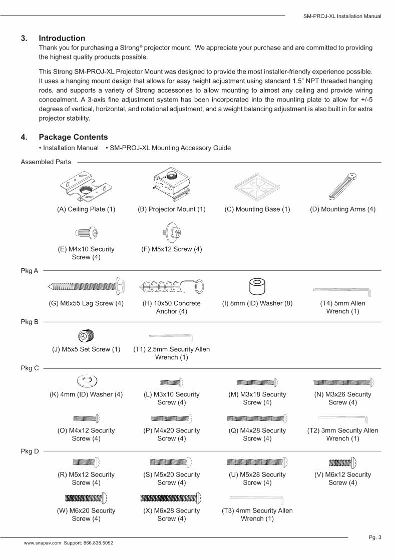
ThankyouforpurchasingaStrong®projectormount.Weappreciateyourpurchaseandarecommittedtoprovidingthehighestqualityproductspossible.
ThisStrongSM-PROJ-XLProjectorMountwasdesignedtoprovidethemostinstaller-friendlyexperiencepossible.Itusesahangingmountdesignthatallowsforeasyheightadjustmentusingstandard1.5”NPTthreadedhangingrods,andsupportsavarietyofStrongaccessories toallowmounting toalmostanyceilingandprovidewiringconcealment.A3-axis fineadjustment systemhasbeen incorporated into themountingplate toallow for+/-5degrees of vertical, horizontal, and rotational adjustment, and a weight balancing adjustment is also built in for extra projector stability.
(A)CeilingPlate(1)
(T3)4mmSecurityAllenWrench(1)
(T4)5mmAllen Wrench(1)
(T2)3mmSecurityAllenWrench(1)
(T1)2.5mmSecurityAllenWrench(1)
(X)M6x28Security Screw(4)
(W)M6x20Security Screw(4)
(V)M6x12Security Screw(4)
(U)M5x28Security Screw(4)
(S)M5x20Security Screw(4)
(R)M5x12Security Screw(4)
(Q)M4x28Security Screw(4)
(N)M3x26Security Screw(4)
(P)M4x20Security Screw(4)
(M)M3x18Security Screw(4)
(O)M4x12Security Screw(4)
(K)4mm(ID)Washer(4) (L)M3x10Security Screw(4)
(G)M6x55LagScrew(4) (H) 10x50 Concrete Anchor(4)
(I)8mm(ID)Washer(8)
(E)M4x10Security Screw(4)
(B) Projector Mount (1) (C) Mounting Base (1) (D)MountingArms(4)
PkgA
AssembledParts
•InstallationManual
Pkg B
Pkg C
PkgD
•SM-PROJ-XLMountingAccessoryGuide
(F)M5x12Screw(4)
(J)M5x5SetScrew(1)

Pg. 4
SM-PROJ-XL Installation Manual
© 2013 Strong®
5. Tools Required• Ladderorscaffoldingtoallowaccesstothemountingarea• Pencil(formakingtemporaryalignmentmarks)• #2PhilipsScrewdriver• Drill• 3/16”Drill(ifmountinginwoodjoistceiling)• 3/8”MasonryBit(ifmountinginconcreteceiling)• Hammer(ifmountinginconcreteceiling)• StudFinder(optional,suggestedforusewithwoodjoistceilings)
6. Installation Considerations
7. Installation
Review this section before beginning to ensure the best possible experience during and after installation of the SM-PROJ-XLprojectormount.
Step 1. Unpack the Projector Mount A. The SM-PROJ-XL is packaged with most of the mount
pre-assembled. While unpacking the mount, refer to thePackage Contents section (Pg. 3) and inventory the parts in thebox.Thepre-assembledpiecesarelistedtogetherforeasy reference.
B. Unscrewtheceilingplate(A)fromtheprojectormount body (B)andremovetheadjustmentknobcover(Figure1).
C. Removethefourscrews(E)usingthe3mmSecurityAllenwrench (T2), and slide the mounting base (C) from the mount body (B).
D. OpenandorganizethehardwarepackagesAand B, which containpartsandtoolsrequiredforinstallationofthemount.PackagesCandDcontainpartsandtoolsforattachingthemounttotheprojector.SettheseasideforuseinStep5ofInstallation.
Figure 1
6.1. Mounting Height and Location • Theidealparametersforprojectorheightanddistancefromthescreenvarydependingontheequipmentin
use and the operating environment. Plan the location that is best for performance according to the screen andprojectorspecifications.
• Makesurethatnothingwillobstructinstallationoftheprojectormountfastenersandwiringinthebuildingstructure,suchasconcealedplumbing,ductwork,electricalwiringorconduit. Ensure thatnoexposeditems on the ceiling or walls will obstruct the line of sight or prevent any part of the system from being mounted correctly.
6.2. Ceiling Mounting Options • The SM-PROJ-XL projector mount and all Strong mounting accessories utilize 1.5” NPT threads for
attachment of mount parts, accessories, and extensions. These optional parts allow for mounting to a varietyofceilingtypesandheights.SeetheSM-PROJ-XLMountingAccessoryGuide(includedinthebox)for more information.
Remove Mount Base Screws (E)(2 per side)
Unscrew Ceiling Plate (A)
RemoveAdjustmentKnob Cover

Pg. 5
SM-PROJ-XL Installation Manual
www.snapav.com Support: 866.838.5052
Step 2. Install the Mounting Plate or Accessory on the CeilingIfanalternativeceilingmountingaccessoryisbeingusedtohangthemountfromtheceiling,refertotheinstallationmanualincludedwithittocompletestep2ofSM-PROJ-XLinstallation.Iftheincludedceilingplateisbeingused,continue with the directions below for either wood or masonry ceiling material mounting.
Warning! When installing the ceiling plate:Do not over-tighten any fasteners used to mount to the ceiling plate. Over-tightening could cause damage to the fasteners, reducing their rated holding strength and increasing the possibility of failure.
Damage to the mount or projector due to improper installation of fasteners is not covered under warranty.
A. Wood Joist Ceiling Instructions1. Locatetheincludedceilingplate(A)and(2)M6x55mmlagscrews(G).
2. Placetheceilingplate(A)inthedesiredlocation,andthenmarkthe two mountingholesandthelocationoftheplate.Theuseofastudfinderishighly recommended to ensure that screws are threaded into the center of the joist above the ceiling surface.
3. Pre-drilleachholeusingadrilland3/16”drillbittoadepthofatleast21/4”.
4. Holdtheplatetightlyinplaceoverthealignmentmarks.Insertthe screws (G) through the plate mounting slots, into the drilled holes, and tighten themusingthe5mmAllenwrench(T4)untiltheplateissecurelyattachedand will not move freely.
(A)
(G)(G)
B. Concrete Ceiling InstructionsWarning! For Concrete or Cinder Block Mounting:Cinder block must meet ASTM C-90 specifications.
Concrete must be 2000 psi density minimum. Lighter density concrete may not hold concrete anchor. Verify that there is a minimum of 1-3/8” of concrete thickness to be used for the included concrete wall anchors.
Do not drill into mortar joints! Be sure to mount in a solid part of the block, generally 1” minimum from the side of the block.
It is suggested that a standard electric drill on slow setting is used to drill the hole instead of a hammer drill to avoid breaking out the back of the hole when entering a void or cavity.
Make sure that the supporting surface will safely support the combined load of the equipment and all attached hardware and components.
Co
rrect
con
cret
eco
ncr
ete
pla
ster
/d
ryw
all
pla
ster
/d
ryw
all
Inco
rrect
CutawayView
Figur
e 2
Cutaway View
1. Locate the ceiling plate (A), (4) 10mmx50mm masonry anchors (H) and (4)M6x55mm lag screws (G).
2. Placetheceilingplate(A)inthedesiredlocation,andthenmarkthefourmounting hole locations and the location of the plate.
3. Usingadrillanda3/8”masonrybit,drilloneholetoadepthofatleast2”(51mm) in each of the four marked locations.
4. Installtheconcreteanchorsintotheholes,tappingtheminlightlywithahammeras needed.
5. Hold theplate tightly in placeover thealignmentmarks. Insert the screws (G)through the plate mounting slots, into the drilled holes, and tighten them using the 5mmAllenwrench(T4)untiltheplateissecurelyattachedandwillnotmovefreely.
(G)x4
(H)x4
(A)
Figure 2
Figure 3
Figure 4

Pg. 6
SM-PROJ-XL Installation Manual
© 2013 Strong®
A. Ifnoadaptersoraccessoriesarebeingused, threadtheprojectormountbody(B)intotheceilingplate(A)byhandastightaspossiblewhile still pointing toward the screen correctly, and then skip to step C.
B. Ifanextensionpoleoraccessorymountisbeingutilized,threadthe extension and any adapters together, and then thread the top of the extensionintotheceilingplate/adapterbyhandastightaspossible.Tighten any set screws for the accessories at this time (see the manualfortheaccessoryortheStrongProjectorMountAccessoryGuide for set screw locations and complete instructions).
C. After themount body (B) is aimed at the screen, use the 2.5mmAllenWrench(T1)andM5x5setscrew(J)tosecurethemountbodyin place. Minor alignment changes can be made later using the adjustment knobs.
Inorderfortheprojectortohangevenlyfromthemountonceitisinstalled,thecenterofgravityoftheprojectormust be aligned to the center of the mounting base. Usually the center of gravity will not be in the center of the unit, butslightlyclosertothesidethelensison.Iftheprojectorhasnomarkingtoindicatethislocation,followthesestepstofindthebalance.
Set Screw Location (shown from two angles)
Step 3. Attach the Projector Mount Body and Optional Extension Accessories
Step 4. Finding the Center of Balance of the Projector
(A)
(B)
ProjectionScreen
Figure 5
Figure 6
Figure 7
(A)
(B)(J)(T1)
(T1)(J)ProjectionScreen
Projection Screen
A. Pickuptheprojectoronoppositesidesandtrytobalance it between both hands. Move your hands forward or back until the projector balances. Once the balance is found, make a temporary mark or note on the projector for reference.
B. Repeat for the opposite axis.
C. The intersection of the lines is the approximate center of balance. Make a temporary mark or note of this point for use in the next step of installation. Center of Balance
Projection Screen

Pg. 7
SM-PROJ-XL Installation Manual
www.snapav.com Support: 866.838.5052
Center of Balance
(D)x4
(F)x4
Projection Screen
Point arrows onmounting base (C)
toward screen
Afterthecenterofbalanceisfound,themountingbaseassemblymustbeattachedtotheprojector.Attachmentwillvaryforalmosteveryprojector,sothepositionofthearmscanbere-configuredasneeded.
Step 5. Attaching the Mounting Base Assembly to the Projector
A. Loosenthefourbolts(F)holdingthearms(D)inplaceto allow enough movement for alignment, then lay the mountingbaseassemblyoverthecenter-of-gravitymarkon the projector and position the arms over the mounting points.
I. Ifthearmswillnotreachalltheholes,theycanbemovedandre-attachedinanyoftheotherslotsonthemountingbaseplate. Ifaprojectorhasonly3holes,simplyremovetheun-neededarm.
II. If an arm is protruding too far out (where it wouldbe visible from below the projector), that arm can be moved to a different slot to allow for a cleaner arrangement.
B. Aftertheideallocationforthearmsisfound,tightenthe armscrews(F)usinga#2Phillipsscrewdriver.
C. Parts (K) through (X) are the screws and washersincluded for attachment of the mount to the projector. There are several lengths in each thread size included forusewiththespacers(I) ifneeded.Testthescrewsin the projector mounting holes until the thread pattern is found.
D. Attachthemountingassemblyusingthelongestscrews with the correct thread pitch that will not bottom out in the projector, but will still tighten completely. Use up to two spacers(I)betweeneacharmandtheprojectortoclearprotrusions if needed.
Note: SeeFigure9foranexampleoftheattachmentof the arm to the projector body.
IftheM3orM4(LthroughQ)screwsareused
for attachment, use the washers (K) between the screw head and the arms.
IftheM5orM6screws(RthroughX)areused
thennowasherisrequired.
Figure 8
Figure 9
Use spacers (I) toadjust clearancebetween mountand projector
M5 and M6 Bolts(R through X)
Use Washer (K)with M3 and M4
Bolts (L through Q)
Pg. 8
SM-PROJ-XL Installation Manual
© 2013 Strong®
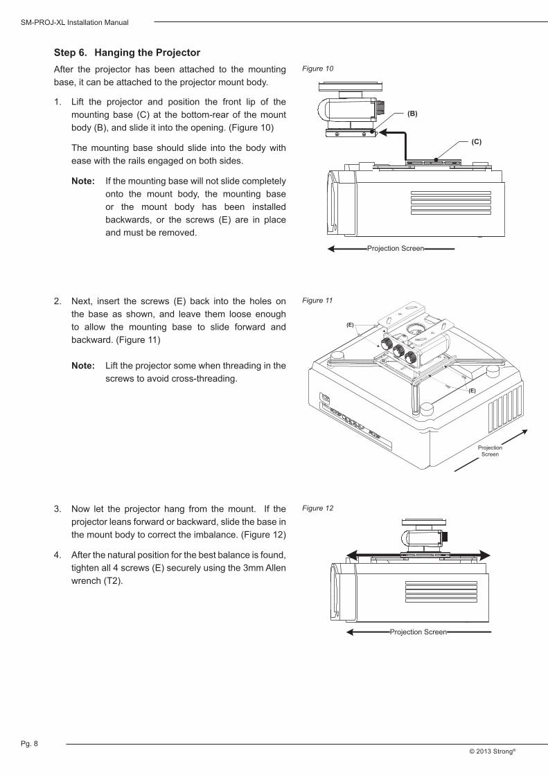
After the projector has been attached to the mountingbase, it can be attached to the projector mount body.
Step 6. Hanging the Projector
1. Lift the projector and position the front lip of the mountingbase (C)at thebottom-rearof themountbody(B),andslideitintotheopening.(Figure10)
The mounting base should slide into the body with ease with the rails engaged on both sides.
Note: Ifthemountingbasewillnotslidecompletelyonto the mount body, the mounting base or the mount body has been installed backwards, or the screws (E) are in placeand must be removed.
Figure 10
Figure 11
Figure 12
Projection Screen
(B)
(C)
ProjectionScreen
(E)
(E)
2. Next, insert the screws (E) back into the holes onthe base as shown, and leave them loose enough to allow the mounting base to slide forward and backward.(Figure11)
Note: Lift the projector some when threading in the
screwstoavoidcross-threading.
3. Now let the projector hang from themount. If theprojector leans forward or backward, slide the base in themountbodytocorrecttheimbalance.(Figure12)
4. Afterthenaturalpositionforthebestbalanceisfound,tightenall4screws(E)securelyusingthe3mmAllenwrench (T2).
\
Projection Screen

Pg. 9
SM-PROJ-XL Installation Manual
www.snapav.com Support: 866.838.5052
Now that themount and projector are fully assembled and installed,make all connections and power on theprojector.Displayanimagefromasourceorapatterngeneratorsothatfinaladjustmentscanbemade.SeeFigure13 below for reference.
Step 7. Adjusting the Projector Image
Move each knob in the desired direction until the image is properly aligned.
Attachthecoverafterfinaladjustmentsarecomplete.TheSM-PROJ-XLmountisnowinstalled.
Note:Thefineadjustmentknobsallowforadjustmentofupto+/-5degreesineachdirection.Iftheadjustmentsdo not allow enough movement to correct an alignment issue, the mount must be adjusted elsewhere.
Figure 13
Adjustment Knobs
A B C
Knob CClockwise
Knob AClockwise
Knob ACounterclockwise
Knob CCounterclockwise
Knob B Clockwise
Knob B Counterclockwise
Knob B Clockwise
Knob B Counterclockwise
Projection Screen
Projected ImageMovement

Pg. 10
SM-PROJ-XL Installation Manual
© 2013 Strong®
9. Dimensions
8. Specifications
Color WhiteorBlackFinish Type PowderCoated,MatteFinishProduct Weight 5 lbs.Security Features IncludessecurityhardwareforattachingprojectorCertifications UL
General
Maximum Projector Weight 50 lbs.Minimum Mounting Pattern 1.96”x1.96”(50mmx50mm)Maximum Mounting Pattern 17.71”x17.71”(450mmx450mm)
Compatibility
Vertical Tilt +/-5°Horizontal Roll +/-5°Horizontal Rotation +/-5°Front to Back Slide 3.5°Offset From Projector 0-.63”(includes2optionalspacersperscrew)
Adjustments
6.30in.
5.18in.
1.38in.
0.31in.
17.71in. (Maximum width)

Pg. 11
SM-PROJ-XL Installation Manual
www.snapav.com Support: 866.838.5052
10. Warranty
11. Contacting Technical Support
Lifetime Limited WarrantyStrong™MountshaveaLifetimeLimitedWarranty.Thiswarrantyincludespartsandlaborrepairson all components found to be defective in material or workmanship under normal conditions of use.Thiswarrantyshallnotapplytoproductswhichhavebeenabused,modifiedordisassembled.ProductstoberepairedunderthiswarrantymustbereturnedtoSnapAVoradesignatedservicecenterwithpriornotificationandanassignedreturnauthorizationnumber(RA).
Lifetime
Phone: (866)838-5052Email: [email protected]

©2013STRONG™130801-1355