slope reinforcement & soil retention - gripple construction/product... · slope reinforcement...
TRANSCRIPT
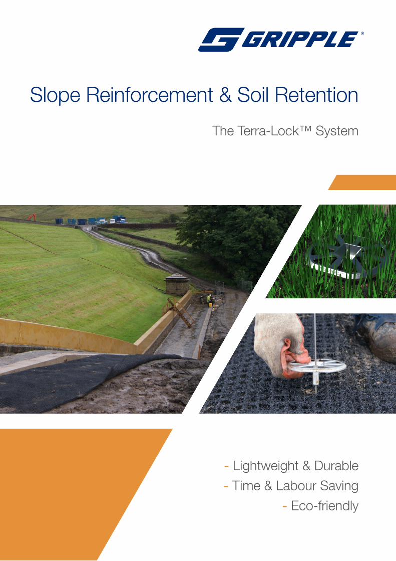
- Lightweight & Durable
- Time & Labour Saving
- Eco-friendly
Slope Reinforcement & Soil Retention
The Terra-Lock™ System
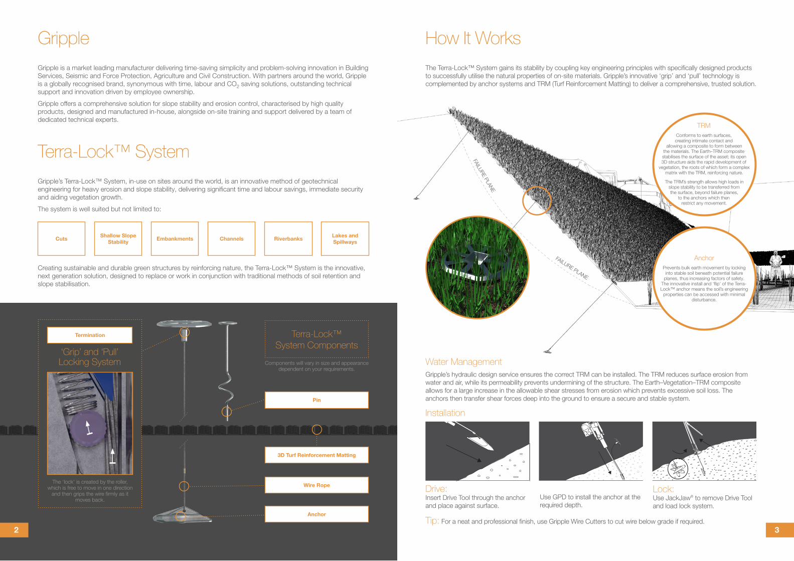
Drive:Insert Drive Tool through the anchor and place against surface.
Tip: For a neat and professional finish, use Gripple Wire Cutters to cut wire below grade if required.
Use GPD to install the anchor at the required depth.
Lock:Use JackJaw® to remove Drive Tool and load lock system.
‘Grip’ and ‘Pull’ Locking System
The Terra-Lock™ System gains its stability by coupling key engineering principles with specifically designed products to successfully utilise the natural properties of on-site materials. Gripple’s innovative ‘grip’ and ‘pull’ technology is complemented by anchor systems and TRM (Turf Reinforcement Matting) to deliver a comprehensive, trusted solution.
FAILURE PLANE
FAILURE PLANE
Gripple’s Terra-Lock™ System, in-use on sites around the world, is an innovative method of geotechnical engineering for heavy erosion and slope stability, delivering significant time and labour savings, immediate security and aiding vegetation growth.
The system is well suited but not limited to:
Creating sustainable and durable green structures by reinforcing nature, the Terra-Lock™ System is the innovative, next generation solution, designed to replace or work in conjunction with traditional methods of soil retention and slope stabilisation.
How It WorksGripple
Terra-Lock™ System
AnchorPrevents bulk earth movement by locking
into stable soil beneath potential failure planes, thus increasing factors of safety.
The innovative install and ‘flip’ of the Terra-Lock™ anchor means the soil’s engineering
properties can be accessed with minimal disturbance.
Installation
TRMConforms to earth surfaces, creating intimate contact and
allowing a composite to form between the materials. The Earth–TRM composite stabilises the surface of the asset; its open 3D structure aids the rapid development of
vegetation, the roots of which form a complex matrix with the TRM, reinforcing nature.
The TRM’s strength allows high loads in slope stability to be transferred from the surface, beyond failure planes,
to the anchors which then restrict any movement.
Water ManagementGripple’s hydraulic design service ensures the correct TRM can be installed. The TRM reduces surface erosion from water and air, while its permeability prevents undermining of the structure. The Earth–Vegetation–TRM composite allows for a large increase in the allowable shear stresses from erosion which prevents excessive soil loss. The anchors then transfer shear forces deep into the ground to ensure a secure and stable system.
Cuts Embankments RiverbanksShallow Slope Stability Channels Lakes and
Spillways
Gripple is a market leading manufacturer delivering time-saving simplicity and problem-solving innovation in Building Services, Seismic and Force Protection, Agriculture and Civil Construction. With partners around the world, Gripple is a globally recognised brand, synonymous with time, labour and CO2 saving solutions, outstanding technical support and innovation driven by employee ownership.
Gripple offers a comprehensive solution for slope stability and erosion control, characterised by high quality products, designed and manufactured in-house, alongside on-site training and support delivered by a team of dedicated technical experts.
Components will vary in size and appearance dependent on your requirements.
The ‘lock’ is created by the roller, which is free to move in one direction
and then grips the wire firmly as it moves back.
Termination Terra-Lock™ System Components
Wire Rope
Pin
Anchor
3D Turf Reinforcement Matting
32
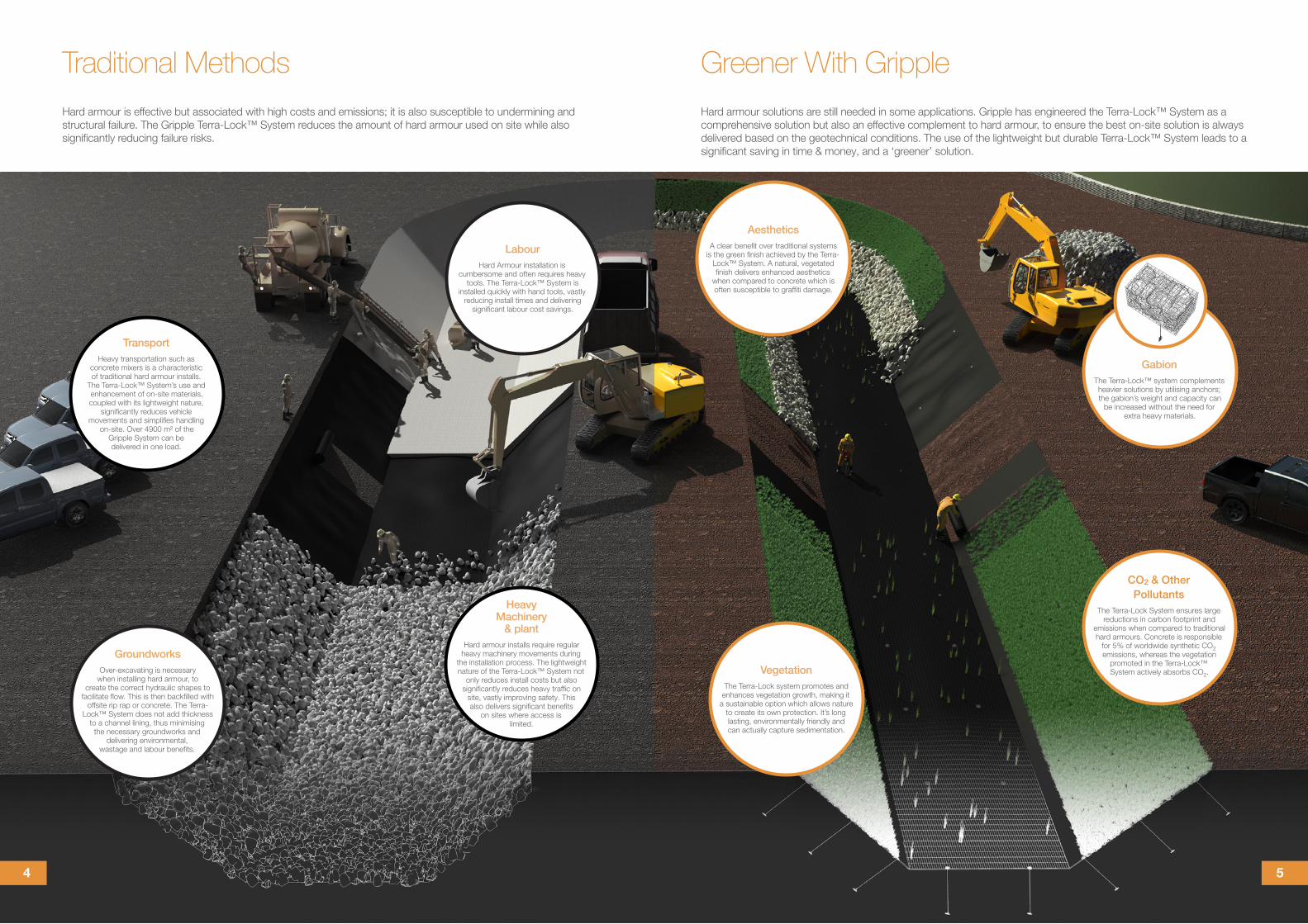
Heavy Machinery
& plantHard armour installs require regular
heavy machinery movements during the installation process. The lightweight nature of the Terra-Lock™ System not
only reduces install costs but also significantly reduces heavy traffic on
site, vastly improving safety. This also delivers significant benefits
on sites where access is limited.
LabourHard Armour installation is
cumbersome and often requires heavy tools. The Terra-Lock™ System is
installed quickly with hand tools, vastly reducing install times and delivering
significant labour cost savings.
GroundworksOver-excavating is necessary
when installing hard armour, to create the correct hydraulic shapes to
facilitate flow. This is then backfilled with offsite rip rap or concrete. The Terra-
Lock™ System does not add thickness to a channel lining, thus minimising
the necessary groundworks and delivering environmental,
wastage and labour benefits.
Hard armour is effective but associated with high costs and emissions; it is also susceptible to undermining and structural failure. The Gripple Terra-Lock™ System reduces the amount of hard armour used on site while also significantly reducing failure risks.
Traditional Methods
GabionThe Terra-Lock™ system complements heavier solutions by utilising anchors; the gabion’s weight and capacity can
be increased without the need for extra heavy materials.
CO2 & Other Pollutants
The Terra-Lock System ensures large reductions in carbon footprint and
emissions when compared to traditional hard armours. Concrete is responsible
for 5% of worldwide synthetic CO2 emissions, whereas the vegetation
promoted in the Terra-Lock™ System actively absorbs CO2.
AestheticsA clear benefit over traditional systems
is the green finish achieved by the Terra-Lock™ System. A natural, vegetated finish delivers enhanced aesthetics
when compared to concrete which is often susceptible to graffiti damage.
Hard armour solutions are still needed in some applications. Gripple has engineered the Terra-Lock™ System as a comprehensive solution but also an effective complement to hard armour, to ensure the best on-site solution is always delivered based on the geotechnical conditions. The use of the lightweight but durable Terra-Lock™ System leads to a significant saving in time & money, and a ‘greener’ solution.
Greener With Gripple
VegetationThe Terra-Lock system promotes and
enhances vegetation growth, making it a sustainable option which allows nature
to create its own protection. It’s long lasting, environmentally friendly and can actually capture sedimentation.
TransportHeavy transportation such as
concrete mixers is a characteristic of traditional hard armour installs.
The Terra-Lock™ System’s use and enhancement of on-site materials, coupled with its lightweight nature,
significantly reduces vehicle movements and simplifies handling
on-site. Over 4900 m² of the Gripple System can be delivered in one load.
54
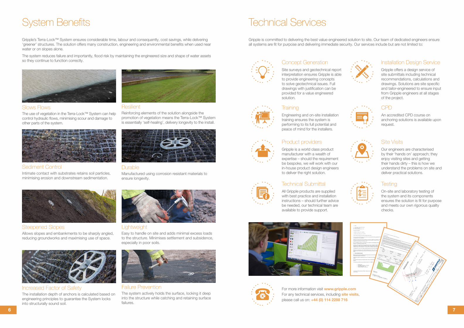
System BenefitsGripple’s Terra-Lock™ System ensures considerable time, labour and consequently, cost savings, while delivering ‘greener’ structures. The solution offers many construction, engineering and environmental benefits when used near water or on slopes alone.
The system reduces failure and importantly, flood risk by maintaining the engineered size and shape of water assets so they continue to function correctly.
Technical Services
Slows FlowsThe use of vegetation in the Terra-Lock™ System can help control hydraulic flows, minimising scour and damage to other parts of the system.
Increased Factor of SafetyThe installation depth of anchors is calculated based on engineering principles to guarantee the System locks into structurally sound soil.
LightweightEasy to handle on site and adds minimal excess loads to the structure. Minimises settlement and subsidence, especially in poor soils.
Steepened SlopesAllows slopes and embankments to be sharply angled, reducing groundworks and maximising use of space.
ResilientReinforcing elements of the solution alongside the promotion of vegetation means the Terra-Lock™ System is essentially ‘self-healing’, delivery longevity to the install.
Sediment ControlIntimate contact with substrates retains soil particles, minimising erosion and downstream sedimentation.
Failure PreventionThe system actively holds the surface, locking it deep into the structure while catching and retaining surface failures.
Gripple is committed to delivering the best value-engineered solution to site. Our team of dedicated engineers ensure all systems are fit for purpose and delivering immediate security. Our services include but are not limited to:
For more information visit www.gripple.comFor any technical services, including site visits, please call us on: +44 (0) 114 2288 716
Concept GenerationSite surveys and geotechnical report interpretation ensures Gripple is able to provide engineering concepts to solve geotechnical issues. Full drawings with justification can be provided for a value engineered solution.
Installation Design ServiceGripple offers a design service of site submittals including technical recommendations, calculations and drawings. Solutions are site specific and tailor-engineered to ensure input from Gripple engineers at all stages of the project.
TrainingEngineering and on-site installation training ensures the system is performing to its full potential and peace of mind for the installers.
CPDAn accredited CPD course on anchoring solutions is available upon request.
Product providersGripple is a world class product manufacturer with a wealth of expertise – should the requirement be bespoke, we will work with our in-house product design engineers to deliver the right solution.
TestingOn-site and laboratory testing of the system and its components ensures the solution is fit for purpose and meets our own rigorous quality checks.
Technical SubmittalAll Gripple products are supplied with best practice and installation instructions – should further advice be needed, our technical team are available to provide support.
Site VisitsOur engineers are characterised by their ‘hands on’ approach; they enjoy visiting sites and getting their hands dirty – this is how we understand the problems on site and deliver practical solutions.
DurableManufactured using corrosion resistant materials to ensure longevity.
τs = γdSo γ = unit weight of water (9810 N/m3) d = depth of flow (m) S0 = Channel Gradient (8.33 x 10⁻⁵) For 0 Km to 2.00 Km τs = 9810 x 4 x 8.33 x 10-5 = 3.26 Pa τs = 9810 x 4.25 x 8.33 x 10-5 = 3.47 Pa This is within the Terra-lock system allowable shear stress.
The flow velocity of 0.76 m/sec is also within the recommended matting capabilities (4 m/s unvegetated and 7m/s vegetated). Gripple Ltd. Always recommends vegetation of channels, establishing vegetation increases both slope and channel bottom factor of safety and thus stability, ultimately without vegetation surficial erosion will always occur. For the vegetation analysis it was assumed to be Bunch with Retardance Class C: Good Stand (6”-11”) and poor coverage < 50%. All designs show significantly improved performance when vegetated, vegetation increases slope factor of safety and thus stability through reducing surface erosion, therefore a vegetated class C: Good Stand (6”-11”) with up 50% coverage is recommended. The Gripple Ltd. Terra-LockTM system indicative spacing’s can be found in appendix drawing.
Gripple Ltd. recommend a 0.5 TL100-TA2 System per m2 and 2 TLP-1 per m2 to achieve intimate contact between the ground and mat, it also helps to achieve an adequate factor of safety.
4. Slope Stability Analysis
Based on the previously established channel geometry and soil information provided, a slope stability analysis was carried out. Gripple are confident in specifying Terra-LockTM system that will adequately stabilise the slopes.
We assumed the slopes are inherently stable in terms of global stability and deep seated failures.
The following conditions were provided at location ‘LS 18500’ for 4m below:
o Cohesive soil o Unit Weight of the Soil γ = 20 kN/m3 o Internal Shear Angle = 12̊ o Cohesive Strength = 58.8 Kn/m2
TL-A2 and TL100 can achieve 145kgf in these soil conditions, this should be verified with onsite testing.
This report was generated by LimitState:GEO3.4.a.20820 - www.limitstate.com
About this ReportThis report has been generated using LimitState:GEO, a software application capable of directly identifying the critical collapse mechanism for a wide variety of
geotechnical stability problems, including those involving slopes, retaining walls, footings etc.
The software utilizes the Discontinuity Layout Optimization (DLO) procedure to obtain a solution (Smith and Gilbert 2007). The main steps involved are: (i) distribution
of nodes across the problem domain; (ii) connection of every node to every other node with potential discontinuities (e.g. slip-lines); (iii) application of rigorous
optimization techniques to identify the critical subset of potential discontinuities, and hence also the critical failure mechanism and margin of safety.
The accuracy of the DLO solution is controlled by the specified nodal density. Within the set of all possible discontinuitiues linking pairs of nodes, all potential
translational failure mechanisms are considered, whether anticipated or not by the engineer. Failure mechanisms involving rotations along the edges of solid bodies
in the problem can also be identified. Thus in this case the solution identified by the DLO procedure is guaranteed to be the most critical solution for the problem
posed. This means that there is no need to prescribe any aspect of the collapse mechanism prior to an analysis, or to separately consider different failure modes.
The critical mechanism and collapse load factor are determined according to the well established upper bound theorem of plasticity.
LimitState:GEO reports the solution to a problem both visually as a collapse mechanism and numerically in terms of an Adequacy Factor, which is defined as the
factor by which specified loads must be increased, or material strengths decreased, in order for the system under consideration to reach a collapse state.
REFERENCE Smith, C.C. and Gilbert, M. (2007) Application of discontinuity layout optimization to plane plasticity problems, Proceedings of the Royal Society A: Mathematical,
Physical and Engineering Sciences, Vol. 463, 2086, pp 2461-2484.
SummaryName
Date of Analysis
Name of Engineer
Organization
Korea, Goodwill
Tue Jan 24 2017
Rob Hepworth
Gripple
Reference #
Location
Map Reference
Tags
Type A
Comments
Target Nodal Density Nodal Spacing ScaleFactor
Water Model Translational
Failures? Model RotationalFailures? Seismic Accelerations:
Horiz. / Vert. (g)
Medium (500 nodes)
13.9394
Enabled
True
Along edges
None
Scenario
Partial Factor Set
Short / Long Term?**
Analysis Type Adequacy Factor
1*
Unity
Long Term
Factor Load(s)
0.5664
*This report provides details of this scenario, which has been identified as the most critical. **For Mohr Coulomb materials with Drainage Behaviour specified as
'drained/undrained', undrained properties are used in a short term analysis, and drained properties are used in a long term analysis.
Failure Mechanism (Scenario 1)
Geometry(all distances in m)
All Geometrical Objects
No. of Vertices (V) No. of Boundaries (B)
No. of Solids (S)
12
14
1
76
BROC-SRSR-ENG-17
WE ARE SOCIAL FOLLOW OUR UPDATES
© 2017 GrippleGripple is a registered trademark of Gripple Limited.
Company registered in England No. 1772901, VAT Reg No. GB 600 1951 88
For details please visit www.gripple.com
Gripple Ltd (Headquarters)
The Old West Gun WorksSavile Street EastSheffield S4 7UQUK
T | +44 (0) 800 018 4264 F | +44 (0)114 275 1155 E | [email protected]
Gripple Inc
1611 Emily Lane Aurora IL 60502 USA
T | +1 866 474 7753 F | +1 800 654 0689 E | [email protected]
Gripple Europe SARL
1, rue du commerce BP 37 67211 Obernai Cedex France
T | +33 (0)3 88 95 44 95 F | +33 (0)3 88 95 08 78 E | [email protected]
Gripple India
B 95/2 Naraina Industrial Area Phase I New Delhi-110028
T | +91 11-40582703 F | +91 11-40582703 E | [email protected]