slide wire dc potentiometer
TRANSCRIPT

Slide Wire Dc Potentiometer
K-13EL-79K-13EL-37K-13EL-28
Group Members

Potentiometer

Types of Dc Potentiometer
• Wire wound potentiometers• Carbon film potentiometers• Plastic film pots
Slide Wire DC Potentiometer
Principle of Operation
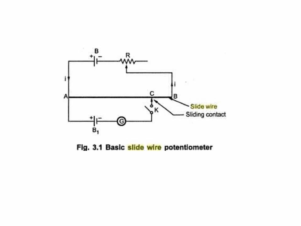
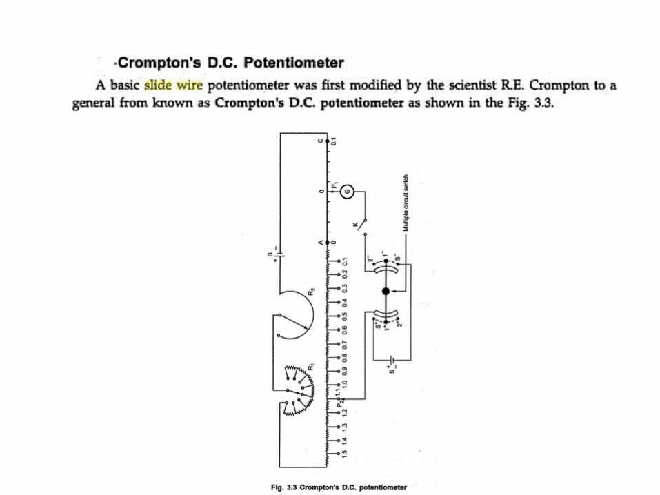
• The basic principle of operation of a Slide Dc potentiometer is illustrated as shown in the Fig.
• A basic potentiometer circuit consists of a slide wire AB of uniform cross section and Unit length. Generally slide wire is made up of manganin. Let r be the resistance per unit Length of slide wire.
• The battery supplies a current through the slide wire which is limited with the help of regulating resistance i.e. rheostat.
• The battery B1 Whose e.m.f. is to be measured is connected in series with a galvanometer G and switch K.
• When the switch K is opened, the current through slide wire is i. If the sliding contact is at position C, let the length AC be Units, then the voltage drop across AC is given by ir1.
• Consider that switch K is closed which puts the battery B1 in the circuit.
• The battery B1 whose e.m.f. is to be measured is connected such that the voltage drop along the slide wire and e.m.f. of B1 oppose each other.
• The deflection in the galvanometer G depends on of magnitude of voltage drop across the slide wire portion AC and e.m.f. of B1.
• If the voltage drop across length l of the slide wire is greater than e.m.f. of battery B1, then the current will flow in the direction A to C through the galvanometer. Similarly if the e.m.f. of battery B1is greater than the voltage drop across the length l of the slide wire, then the current will flow in the direction C to A through the galvanometer.
• The most important condition exhibiting the basic principle of the potentiometer is that no current flows through the galvanometer when the two e.m.f’s are equal.
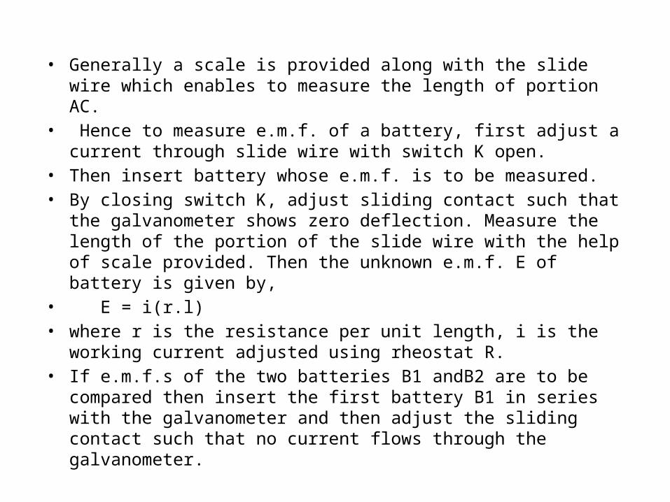
• Generally a scale is provided along with the slide wire which enables to measure the length of portion AC.
• Hence to measure e.m.f. of a battery, first adjust a current through slide wire with switch K open.
• Then insert battery whose e.m.f. is to be measured. • By closing switch K, adjust sliding contact such that the galvanometer
shows zero deflection. Measure the length of the portion of the slide wire with the help of scale provided. Then the unknown e.m.f. E of battery is given by,
• E = i(r.l)• where r is the resistance per unit length, i is the working current adjusted
using rheostat R.• If e.m.f.s of the two batteries B1 andB2 are to be compared then insert the
first battery B1 in series with the galvanometer and then adjust the sliding contact such that no current flows through the galvanometer.
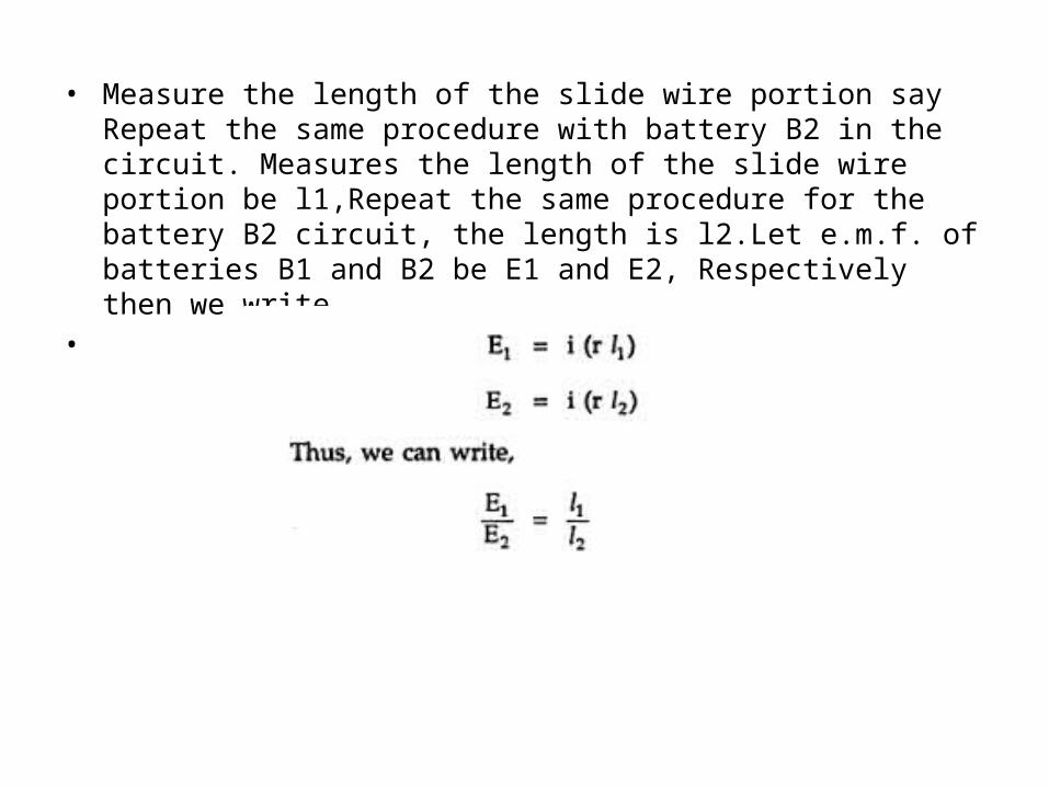
• Measure the length of the slide wire portion say Repeat the same procedure with battery B2 in the circuit. Measures the length of the slide wire portion be l1,Repeat the same procedure for the battery B2 circuit, the length is l2.Let e.m.f. of batteries B1 and B2 be E1 and E2, Respectively then we write
•
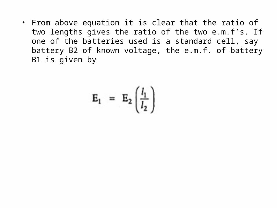
• From above equation it is clear that the ratio of two lengths gives the ratio of the two e.m.f’s. If one of the batteries used is a standard cell, say battery B2 of known voltage, the e.m.f. of battery B1 is given by
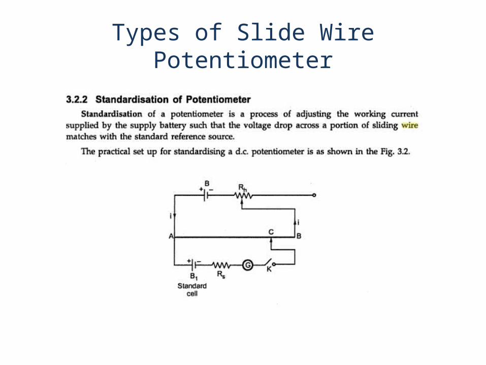
Types of Slide Wire Potentiometer


REFFERENCE
Instrumentation and Measurements
U.A BakshiA.V Bakshi