sip sip industriessip industries ez gripsipindustries.com/dwlpdf/ezgripdi.pdf · installation...
TRANSCRIPT
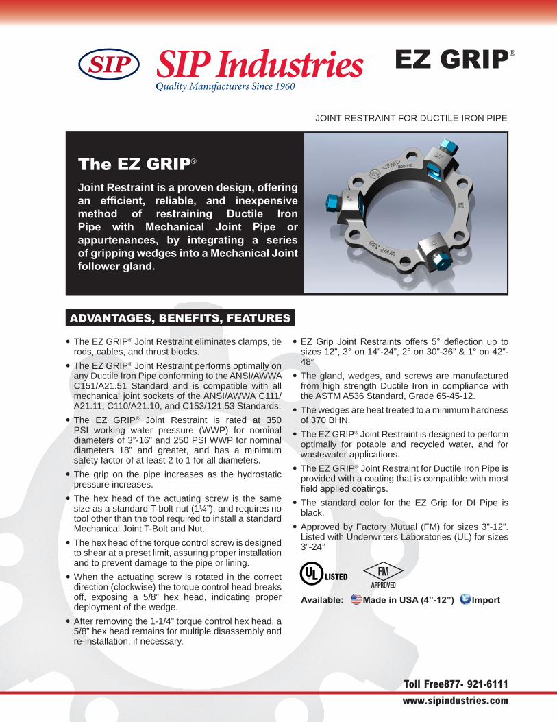
The EZ GRIP® Joint Restraint is a proven design, offering an efficient, reliable, and inexpensive method of restraining Ductile Iron Pipe with Mechanical Joint Pipe or appurtenances, by integrating a series of gripping wedges into a Mechanical Joint follower gland.
ADVANTAGES, BENEFITS, FEATURES
• The EZ GRIP® Joint Restraint eliminates clamps, tierods, cables, and thrust blocks.
• The EZ GRIP® Joint Restraint performs optimally onany Ductile Iron Pipe conforming to the ANSI/AWWA C151/A21.51 Standard and is compatible with allmechanical joint sockets of the ANSI/AWWA C111/A21.11, C110/A21.10, and C153/121.53 Standards.
• The EZ GRIP® Joint Restraint is rated at 350PSI working water pressure (WWP) for nominaldiameters of 3”-16” and 250 PSI WWP for nominaldiameters 18” and greater, and has a minimumsafety factor of at least 2 to 1 for all diameters.
• The grip on the pipe increases as the hydrostaticpressure increases.
• The hex head of the actuating screw is the samesize as a standard T-bolt nut (1¼”), and requires notool other than the tool required to install a standardMechanical Joint T-Bolt and Nut.
• The hex head of the torque control screw is designed to shear at a preset limit, assuring proper installationand to prevent damage to the pipe or lining.
• When the actuating screw is rotated in the correctdirection (clockwise) the torque control head breaksoff, exposing a 5/8” hex head, indicating properdeployment of the wedge.
• After removing the 1-1/4” torque control hex head, a5/8” hex head remains for multiple disassembly andre-installation, if necessary.
• EZ Grip Joint Restraints offers 5° deflection up tosizes 12”, 3° on 14”-24”, 2° on 30”-36” & 1° on 42”-48”
• The gland, wedges, and screws are manufacturedfrom high strength Ductile Iron in compliance withthe ASTM A536 Standard, Grade 65-45-12.
• The wedges are heat treated to a minimum hardness of 370 BHN.
• The EZ GRIP® Joint Restraint is designed to performoptimally for potable and recycled water, and forwastewater applications.
• The EZ GRIP® Joint Restraint for Ductile Iron Pipe isprovided with a coating that is compatible with mostfield applied coatings.
• The standard color for the EZ Grip for DI Pipe isblack.
• Approved by Factory Mutual (FM) for sizes 3”-12”.Listed with Underwriters Laboratories (UL) for sizes3”-24”
EZ GRIP®
JOINT RESTRAINT FOR DUCTILE IRON PIPE
Quality Manufacturers Since 1960SIP IndustriesQuality Manufacturers Since 1960SIP Industries
Toll Free 877- 921-6111
www.sipindustries.com
Available: Made in USA (4”-12”) Import
20144897_EZGripDI_r3.indd 1 12/18/14 11:04 PM
SIP
Installation Procedure for restraining mechanical joint appurtenances on ductile iron pipe conforming to ANSI/AWWA C151/A21.51.
Installation Procedure
Toll Free 877-921-6111
www.sipindustries.com
EZ GRIP®
JOINT RESTRAINT FOR DUCTILE IRON PIPE
TOP BOTTOM
J
X K2
A
A
0.12
D
.75
SECTION A-A
All dimensions are in inches, unless otherwise noted
(D) Made in USA
(I) Import
* Requirement of AWWA C600EZ-GRIP DI RESTRAINTS SPECIFICATIONS
FC
P
TOP BOTTOM
J
X K2
A
A
0.12
D
.75
SECTION A-A
All dimensions are in inches, unless otherwise noted
(D) Made in USA
(I) Import
* Requirement of AWWA C600EZ-GRIP DI RESTRAINTS SPECIFICATIONS
FC
P
SIP IndustriesSIP Industries
20144897_EZGripDI_r3.indd 2 12/18/14 11:04 PM
SIP
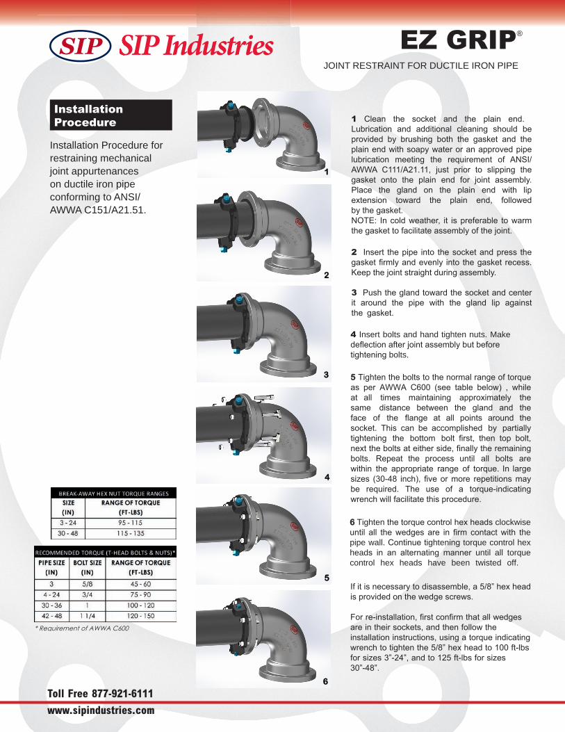
1 Clean the socket and the plain end. Lubrication and additional cleaning should be provided by brushing both the gasket and the plain end with soapy water or an approved pipe lubrication meeting the requirement of ANSI/AWWA C111/A21.11, just prior to slipping the gasket onto the plain end for joint assembly. Place the gland on the plain end with lip extension toward the plain end, followed by the gasket.NOTE: In cold weather, it is preferable to warm the gasket to facilitate assembly of the joint.
2 Insert the pipe into the socket and press the gasket firmly and evenly into the gasket recess. Keep the joint straight during assembly.
3 Push the gland toward the socket and center it around the pipe with the gland lip against the gasket.
5 Tighten the bolts to the normal range of torque as per AWWA C600 (see table below) , while at all times maintaining approximately the same distance between the gland and the face of the flange at all points around the socket. This can be accomplished by partially tightening the bottom bolt first, then top bolt, next the bolts at either side, finally the remaining bolts. Repeat the process until all bolts are within the appropriate range of torque. In large sizes (30-48 inch), five or more repetitions may be required. The use of a torque-indicating wrench will facilitate this procedure.
6 Tighten the torque control hex heads clockwise until all the wedges are in firm contact with the pipe wall. Contin e tightening torque control hex heads in an alternating anner until all torque control hex heads have been twisted off.
If it is necessary to disassemble, a 5/8” hex head is provided on the wedge screws.
For re-installation, first confirm that all wedges are in their sockets, and then follow the installation instructions, using a torque indicating wrench to tighten the 5/8” hex head to 100 ft-lbs for sizes 3”-24”, and to 125 ft-lbs for sizes 30”-48”.
4 Insert bolts and hand tighten nuts. Make deflection after joint assembly but before tightening bolts.
2
3
4
5
6
1

Technical Data
Toll Free 877- 921-6111
www.sipindustries.com
EZ GRIP®
JOINT RESTRAINT FOR DUCTILE IRON PIPE
TOP BOTTOM
J
X K2
A
A
0.12
D
.75
SECTION A-A
All dimensions are in inches, unless otherwise noted
(D) Made in USA
(I) Import
EZ-GRIP DI RESTRAINTS SPECIFICATIONS
FC
P
0.12
D
.75
SECTION A-A
All dimensions are in inches, unless otherwise noted
(D) Made in USA
(I) Import
* Requirement of AWWA C600EZ-GRIP DI RESTRAINTS SPECIFICATIONS
FC
P
TOP BOTTOM
J
X K2
A
A
All dimensions are in inches, unless otherwise noted
(D) Made in USA
(I) Import
* Requirement of AWWA C600EZ-GRIP DI RESTRAINTS SPECIFICATIONS
SIP IndustriesSIP Industries
20144897_EZGripDI_r3.indd 3 12/18/14 11:04 PM
TOP BOTTOM
J
X K2
A
A 0.12
D
.75
SECTION A-A
FC
P
SIP

The mechanical joint restraining mechanism and the follower gland shall be designed and manufactured as one integral device providing for a joint seal and performing as a joint restraint. This shall be achieved by a series of individually activated wedges gripping the outside wall of the Ductile Iron Pipe. The grip of the wedges shall increase as the hydrostatic pressure increases.
There shall be no additional tool required for installation other than the tool required to install a standard Mechanical Joint T-Bolt and 1-1/4” Nut. The hex head of the actuating screw shall be designed to break off at a preset torque. After the removal of the 1-1/4” torque control hex head, a 5/8” hex head on the actuating screw shall remain, to allow for the disassembly and re-installation of the gland and restraint.
The gland, screws, and wedges shall be manufactured of high strength ductile iron in accordance with the ASTM A536 Standard, Grade 65-45-12. The wedges shall be heat treated to a minimum hardness of 370 BHN.
The mechanical joint restraint mechanism shall be rated at 350 PSI working water pressure for nominal diameters of 3”-16” and 250 PSI WWP for nominal diameters 18” and greater with a 2:1 safety factor. The restraint device shall perform optimally on any Ductile Iron Pipe conforming to the ANSI/AWWA C151/A21.51 Standard and the gland shall comply with all applicable dimensions of, and be compatible with, all mechanical joint sockets of ANSI/AWWA C111/A21.11, C110/A21.10, and C153/121.53 Standards.
The EZGrip mechanical joint restraint mechanism for ductile iron pipe shall be approved by Factory Mutual for sizes 3”-12” and listed by Underwriters Laboratories for sizes 3”-24”. The restraint device for Ductile Iron Pipe shall be SIP Industries series EZD or equal.
SAMPLE SPECIFICATIONS
EZ GRIP®
JOINT RESTRAINT FOR DUCTILE IRON PIPE
Available: Made in USA (4”-12”) Import
Phone: 877-921-6111 or 713-923-6111 | Fax: 713-923-6114 | www.sipindustries.com | [email protected]
AWWA DI Fittings & Accessories
C153 Compact MJ Fittings and Acc. 2” – 48” C110 Full Body MJ Fittings 2” - 48” C153 Push-On Fittings 4” - 24” C110 Flange Fittings 2” - 60” Stainless Steel & Blue T-Bolts Ductile Iron Retainer Glands Made in India, China & Mexico Cement, Fusion Bonded Epoxy & P401 lining.
Joint Restraint System
EZD Joint Restraint for DI Pipe 3” - 48” EZP Joint Restraint for PVC Pipe 3” - 36” PTP Pipe to Pipe Restraint 4” - 36” PTPDF Pipe to MJ Fittings Restraint 4” - 36”PTPFC Pipe to PVC Fittings Restraint 4” - 12”Pipe to Pipe Restraints for DI Pipes & Fittings 4" - 16"MJ X MJ Adapter for Connecting Two MJ BellsMade in China & USA Fusion Bonded Epoxy or Shop Coating.
Municipal Construction Castings
Manhole Rings and Cover Frames and Grates Valve Boxes and Service Boxes Water Meter Covers and Boxes Trench Grates and Tree Grates Made in India & USA
Fabrication Products for DI Pipe
High Hub Flanges Class 150 and 250. 3” - 64” Threaded Bell Flanges 3” - 48” Anchor Flanges 3” - 60” Filler Flanges 4” - 30”
Other Products and Services
All Thread Rod Pipe Lube and Hydraulic Cement Socket Clamps and Lugs Flange Packs OEM Castings
Quality Manufacturers Since 1960SIP IndustriesQuality Manufacturers Since 1960SIP Industries
20144897_EZGripDI_r3.indd 4 12/18/14 11:04 PM
SIP East 600 Rayloc Drive Atlanta, GA 30336
SIP West8333 Almeria Avenue
Fontana, CA 92335
SIP Central 2900 Patio Drive
Houston, TX 77017
SIP Corporate 8876 Gulf Freeway Suite 500
Houston, TX 77017
SIP