sinumerik connecting 3 - bolton tools · 2016-01-04 · the sinumerik 808d is an economical cnc...
TRANSCRIPT
� �Electrical Installation Manual
___________________
___________________
___________________
___________________
___________________
___________________
SINUMERIK
SINUMERIK 808D Electrical Installation Manual
Operating Instructions
Valid for: SINUMERIK 808D Turning (software version: V4.4.2) SINUMERIK 808D Milling (software version: V4.4.2) Target group: Electrical engineers and electrical assembly workers
12/2012 6FC5397-2EP10-0BA0
Preface
Safety instructions 1
System overview 2
Connecting 3
Technical specifications 4
Appendix A
Siemens AG Industry Sector Postfach 48 48 90026 NÜRNBERG GERMANY
Order number: 6FC5397-2EP10-0BA0 Ⓟ 12/2012 Technical data subject to change
Copyright © Siemens AG 2012. All rights reserved
Legal information Warning notice system
This manual contains notices you have to observe in order to ensure your personal safety, as well as to prevent damage to property. The notices referring to your personal safety are highlighted in the manual by a safety alert symbol, notices referring only to property damage have no safety alert symbol. These notices shown below are graded according to the degree of danger.
DANGER indicates that death or severe personal injury will result if proper precautions are not taken.
WARNING indicates that death or severe personal injury may result if proper precautions are not taken.
CAUTION indicates that minor personal injury can result if proper precautions are not taken.
NOTICE indicates that property damage can result if proper precautions are not taken.
If more than one degree of danger is present, the warning notice representing the highest degree of danger will be used. A notice warning of injury to persons with a safety alert symbol may also include a warning relating to property damage.
Qualified Personnel The product/system described in this documentation may be operated only by personnel qualified for the specific task in accordance with the relevant documentation, in particular its warning notices and safety instructions. Qualified personnel are those who, based on their training and experience, are capable of identifying risks and avoiding potential hazards when working with these products/systems.
Proper use of Siemens products Note the following:
WARNING Siemens products may only be used for the applications described in the catalog and in the relevant technical documentation. If products and components from other manufacturers are used, these must be recommended or approved by Siemens. Proper transport, storage, installation, assembly, commissioning, operation and maintenance are required to ensure that the products operate safely and without any problems. The permissible ambient conditions must be complied with. The information in the relevant documentation must be observed.
Trademarks All names identified by ® are registered trademarks of Siemens AG. The remaining trademarks in this publication may be trademarks whose use by third parties for their own purposes could violate the rights of the owner.
Disclaimer of Liability We have reviewed the contents of this publication to ensure consistency with the hardware and software described. Since variance cannot be precluded entirely, we cannot guarantee full consistency. However, the information in this publication is reviewed regularly and any necessary corrections are included in subsequent editions.
Electrical Installation Manual Operating Instructions, 12/2012, 6FC5397-2EP10-0BA0 3
Preface
SINUMERIK 808D documentation The SINUMERIK 808D documentation consists of the following components:
● Operating Instructions
– Mechanical Installation Manual
– Electrical Installation Manual
– PLC Subroutines Manual
– Function Manual
– Parameter Manual
● Diagnostics Manual
● Commissioning Manual
● Programming and Operating Manual (Turning)
● Programming and Operating Manual (Milling)
● Manual Machine Plus (Turning)
● Online Help for Programming and Operating (Turning)
● Online Help for Programming and Operating (Milling)
● Online Help for Manual Machine Plus (Turning)
My Documentation Manager (MDM) Under the following link you will find information to individually compile your documentation based on the Siemens content:
www.siemens.com/mdm
Target group This manual is intended for use by electrical engineers and electrical assembly workers.
Benefits This manual enables the intended target groups to properly and safely connect up the SINUMERIK 808D system.
Preface
Electrical Installation Manual 4 Operating Instructions, 12/2012, 6FC5397-2EP10-0BA0
Technical support Hotline: +86 400-810-4288 Service and Support China:
www.siemens.com.cn/808D Worldwide:
http://support.automation.siemens.com
EC Declaration of Conformity The EC Declaration of Conformity for the EMC Directive can be found on the Internet at http://support.automation.siemens.com.
Here, enter the number 15257461 as the search term or contact your local Siemens office.
Licensing provisions The SINUMERIK 808D software is protected by national and international copyright laws and agreements. Unauthorized reproduction and distribution of this software or parts thereof is liable to prosecution. It will be prosecuted both according to criminal and civil law and may result in severe penalties or claims for compensation.
In the SINUMERIK 808D software, open source software is used. The licensing provisions for this software are included on the Toolbox DVD and are to be observed accordingly.
Electrical Installation Manual Operating Instructions, 12/2012, 6FC5397-2EP10-0BA0 5
Table of contents
Preface ...................................................................................................................................................... 3
1 Safety instructions ..................................................................................................................................... 7
2 System overview...................................................................................................................................... 11
3 Connecting .............................................................................................................................................. 15
3.1 Interface overview........................................................................................................................15
3.2 Connection Overview for SINUMERIK 808D...............................................................................17
3.3 Connecting the interfaces on the PPU.........................................................................................19 3.3.1 Digital input interfaces - X100, X101, X102 .................................................................................19 3.3.2 Digital output interfaces - X200, X201 .........................................................................................21 3.3.3 Fast input/output - X21.................................................................................................................22 3.3.4 Distributed I/O - X301, X302........................................................................................................25 3.3.5 Handwheel inputs - X10...............................................................................................................29 3.3.6 Pulse drive interfaces - X51, X52, X53 ........................................................................................30 3.3.7 Analog spindle interface - X54.....................................................................................................33 3.3.8 Spindle encoder interface - X60...................................................................................................35 3.3.9 RS232 interface - X2....................................................................................................................36 3.3.10 Power supply interface - X1 .........................................................................................................37 3.3.11 USB interface on the front cover of the PPU ...............................................................................38 3.3.12 USB interface - X30 .....................................................................................................................38 3.3.13 Battery interface...........................................................................................................................39 3.3.14 Slot for the system CompactFlash Card (CF card)......................................................................40
3.4 Connecting the USB interface on the MCP .................................................................................40
4 Technical specifications........................................................................................................................... 41
4.1 Radio interference........................................................................................................................42
A Appendix.................................................................................................................................................. 43
A.1 ESD Directive...............................................................................................................................43 A.1.1 What does ESD mean? ...............................................................................................................43 A.1.2 Electrostatic Discharge to Persons..............................................................................................44 A.1.3 Basic protective measures against discharge of static electricity................................................44
A.2 Order numbers.............................................................................................................................45
A.3 FAQs ............................................................................................................................................46
Index........................................................................................................................................................ 47

Table of contents
Electrical Installation Manual 6 Operating Instructions, 12/2012, 6FC5397-2EP10-0BA0
Electrical Installation Manual Operating Instructions, 12/2012, 6FC5397-2EP10-0BA0 7
Safety instructions 1
General
WARNING Death or serious injury may occur.
Only qualified personnel should be allowed to work on this control system, and only after becoming acquainted with all the safety notices regarding installing as set out in this manual.
Failure to observe these notices contained in this manual can result in death, severe personal injury or considerable damage to property.
Without prior authorization, you are not allowed to perform any modification on the machine.
Identification
NOTICE Property loss
Deliverables received should be complete and intact. Exercise caution to ensure that you do not put a damaged device into service.
Otherwise, you may suffer property loss.
Make sure that the PPU, the MCP and the cables received correspond with the specific package you ordered from Siemens.
Transport and storage
Note
Transport and storage should meet specified environmental conditions.
Safety instructions
Electrical Installation Manual 8 Operating Instructions, 12/2012, 6FC5397-2EP10-0BA0
Mechanical installation
DANGER Death or serious injury from electric shock
The equipment which is not diconnected from the mains or properly protected contains hazardous voltage.
Such a voltage may lead to death or serious injury.
Before installing or removing the components of the control system, make sure that the system is disconnected from the mains. In addition, do install the control system in a distribution cabinet with an adequate protection level.
DANGER Death or serious injury from fire or electric shock
If the equipment operates in an area subject to inflammables or combustibles, water or corrosion hazards, it contains high risk of fire or electric shock.
The fire or electric shock may lead to death or serious injury.
Do install the control system in an area free of inflammables or combustibles, water or corrosion hazards.
Note
When dimensioning the control cabinet, make sure that the installed components do not exceed the permissible ambient temperature, even if the outside temperature is high.
Electrical installation
CAUTION Damage to the control system
The high-voltage components have strong interference in 24 V DC power supply.
If the 24 V DC power supply is not isolated from high-voltage components, the control system may be damaged.
The 24 V DC protective extra-low voltage must be generated as a protective extra-low voltage with safe electrical isolation (to IEC 204-1, Section 6.4, PELV), and grounded by with a PELV M signal connection to the central grounding point of the system.
Safety instructions
Electrical Installation Manual Operating Instructions, 12/2012, 6FC5397-2EP10-0BA0 9
DANGER Death or serious injury from electric shock
The equipment which is not disconnected from the mains contains hazardous voltage.
Such a voltage may lead to death or serious injury.
Before connecting the modules, first disconnect the equipment from the mains!
NOTICE EMC requirements will not be met.
The unshielded or ungrounded FAST I/O cable is very sensitive to ambient electromagnetic interference.
In this case, relevant EMC requirements will be not be met.
In order to meet IEC/CISPR requirements, the FAST I/O cable must be shielded and grounded.
Commissioning
Note
Do not forget to back up data after completing the commissioning work.
Note
Clear the manufacturer password before the machine is delivered; otherwise, end users can start the controller with the standard data, which can initialize the SINUMERIK 808D control system. As a consequence, the machine will not run.

Safety instructions
Electrical Installation Manual 10 Operating Instructions, 12/2012, 6FC5397-2EP10-0BA0
Electrical Installation Manual Operating Instructions, 12/2012, 6FC5397-2EP10-0BA0 11
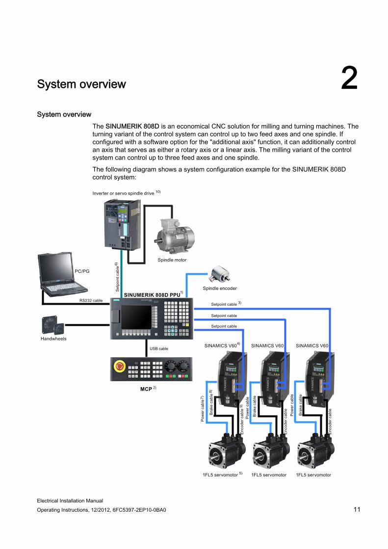
System overview 2System overview
The SINUMERIK 808D is an economical CNC solution for milling and turning machines. The turning variant of the control system can control up to two feed axes and one spindle. If configured with a software option for the "additional axis" function, it can additionally control an axis that serves as either a rotary axis or a linear axis. The milling variant of the control system can control up to three feed axes and one spindle.
The following diagram shows a system configuration example for the SINUMERIK 808D control system:
SINUMERIK 808D PPU
MCP

System overview
Electrical Installation Manual 12 Operating Instructions, 12/2012, 6FC5397-2EP10-0BA0
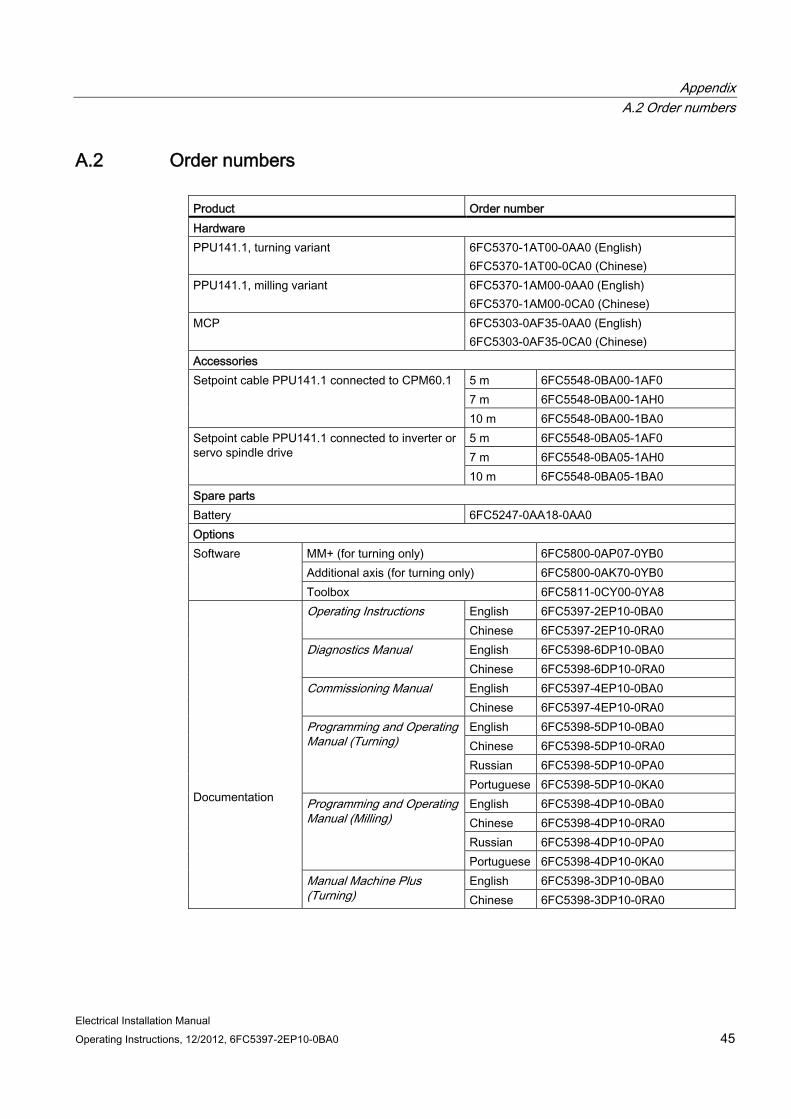
Legend Name Order number
PPU141.1, turning 6FC5370-1AT00-0AA0 (English) 6FC5370-1AT00-0CA0 (Chinese)
1)
PPU141.1, milling 6FC5370-1AM00-0AA0 (English) 6FC5370-1AM00-0CA0 (Chinese)
2) MCP 6FC5303-0AF35-0AA0 (English) 6FC5303-0AF35-0CA0 (Chinese) 6FC5548-0BA00-1AF0 (5 m) 6FC5548-0BA00-1AH0 (7 m)
3) Setpoint cable PPU141.1 to CPM60.1
6FC5548-0BA00-1BA0 (10 m) 6SL3210-5CC14-0UA0 (4 A) 6SL3210-5CC16-0UA0 (6 A) 6SL3210-5CC17-0UA0 (7 A)
4) SINAMICS V60 Controlled Power Module (CPM60.1)
6SL3210-5CC21-0UA0 (10 A) 1FL5060-0AC21-0AA0 (4 Nm, with key, without brake) 1FL5060-0AC21-0AG0 (4 Nm, without key, without brake) 1FL5062-0AC21-0AA0 (6 Nm, with key, without brake) 1FL5062-0AC21-0AG0 (6 Nm, without key, without brake) 1FL5064-0AC21-0AA0 (7.7 Nm, with key, without brake) 1FL5064-0AC21-0AG0 (7.7 Nm, without key, without brake) 1FL5066-0AC21-0AA0 (10 Nm, with key, without brake) 1FL5066-0AC21-0AG0 (10 Nm, without key, without brake) 1FL5060-0AC21-0AB0 (4 Nm, with key, with brake) 1FL5060-0AC21-0AH0 (4 Nm, without key, with brake) 1FL5062-0AC21-0AB0 (6 Nm, with key, with brake) 1FL5062-0AC21-0AH0 (6 Nm, without key, with brake) 1FL5064-0AC21-0AB0 (7.7 Nm, with key, with brake) 1FL5064-0AC21-0AH0 (7.7 Nm, without key, with brake) 1FL5066-0AC21-0AB0 (10 Nm, with key, with brake)
5) 1FL5 Motor
1FL5066-0AC21-0AH0 (10 Nm, without key, with brake)

System overview
Electrical Installation Manual Operating Instructions, 12/2012, 6FC5397-2EP10-0BA0 13
Legend Name Order number 6FC5548-0BA05-1AF0 (5 m) 6FC5548-0BA05-1AH0 (7 m)
6) Setpoint cable PPU141.1 to inverter or servo spindle drive
6FC5548-0BA05-1BA0 (10 m) 6FX6002-5LE00-1AF0 (5 m) 7) Power cable (unshielded) 6FX6002-5LE00-1BA0 (10 m) 6FX6002-2BR00-1AF0 (5 m) 8) Brake cable (unshielded) 6FX6002-2BR00-1BA0 (10 m) 6FX6002-2LE00-1AF0 (5 m) 9) Encoder cable (shielded) 6FX6002-2LE00-1BA0 (10 m)
10) Inverter or servo spindle drive From Siemens or a third-party manufacturer
System structure The structure of the SINUMERIK 808D control system is shown as follows:
● CNC Unit
– Panel Processing Unit (PPU)
– Machine Control Panel (MCP)
– Setpoint cable to SINAMICS V60
– Setpoint cable to the spindle
● Drive unit
– SINAMICS V60 (for controlling feed axes)
– 1FL5 motor
– Power cable
– Encoder cable
– Brake cable (for motors with brake)
– Inverter or servo spindle drive (for controlling the spindle)
– Spindle motor
– Spindle encoder
● Electronic handwheels
A maximum of two handwheels can be connected

System overview
Electrical Installation Manual 14 Operating Instructions, 12/2012, 6FC5397-2EP10-0BA0

Electrical Installation Manual Operating Instructions, 12/2012, 6FC5397-2EP10-0BA0 15
Connecting 33.1 Interface overview
Interface overview on the Panel Processing Unit (PPU)
2
1 5 6 7 8 9 10
11
12
13
4
3
14
Figure 3-1 Interface layout
Legend Interface Comment Rear
① X100, X101, X102 Digital inputs
② X200, X201 Digital outputs
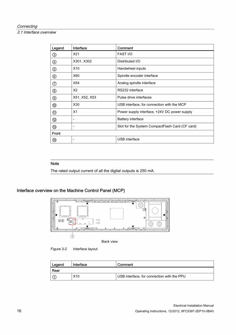
Connecting 3.1 Interface overview
Electrical Installation Manual 16 Operating Instructions, 12/2012, 6FC5397-2EP10-0BA0
Legend Interface Comment
③ X21 FAST I/O
④ X301, X302 Distributed I/O
⑤ X10 Handwheel inputs
⑥ X60 Spindle encoder interface
⑦ X54 Analog spindle interface
⑧ X2 RS232 interface
⑨ X51, X52, X53 Pulse drive interfaces
⑩ X30 USB interface, for connection with the MCP
⑪ X1 Power supply interface, +24V DC power supply
⑫ - Battery interface
⑬ - Slot for the System CompactFlash Card (CF card)
Front
⑭ - USB interface
Note
The rated output current of all the digital outputs is 250 mA.
Interface overview on the Machine Control Panel (MCP)
1
Figure 3-2 Interface layout
Legend Interface Comment Rear
① X10 USB interface, for connection with the PPU
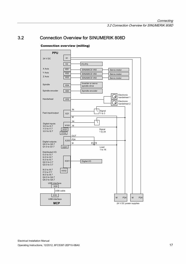
Connecting 3.2 Connection Overview for SINUMERIK 808D
Electrical Installation Manual Operating Instructions, 12/2012, 6FC5397-2EP10-0BA0 17
3.2 Connection Overview for SINUMERIK 808D Connection overview (milling)
MCP
PPU
Connecting 3.2 Connection Overview for SINUMERIK 808D
Electrical Installation Manual 18 Operating Instructions, 12/2012, 6FC5397-2EP10-0BA0
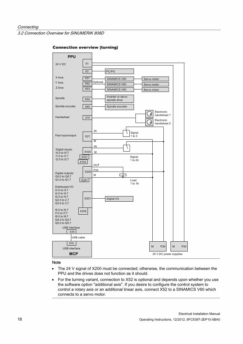
Connection overview (turning)
PPU
MCP Note
The 24 V signal of X200 must be connected; otherwise, the communication between the PPU and the drives does not function as it should.
For the turning variant, connection to X52 is optional and depends upon whether you use the software option "additional axis". If you desire to configure the control system to control a rotary axis or an additional linear axis, connect X52 to a SINAMICS V60 which connects to a servo motor.
Connecting 3.3 Connecting the interfaces on the PPU
Electrical Installation Manual Operating Instructions, 12/2012, 6FC5397-2EP10-0BA0 19
3.3 Connecting the interfaces on the PPU
3.3.1 Digital input interfaces - X100, X101, X102 Type Mini Combicon 10-pin Cable Max. length: 10 m
Max. cross-section: One cable per connection: ≥ 0.5 mm2
Inputs Permissible level (including ripple) High level: 18 V - 30 V Low level: -3 V - +5 V
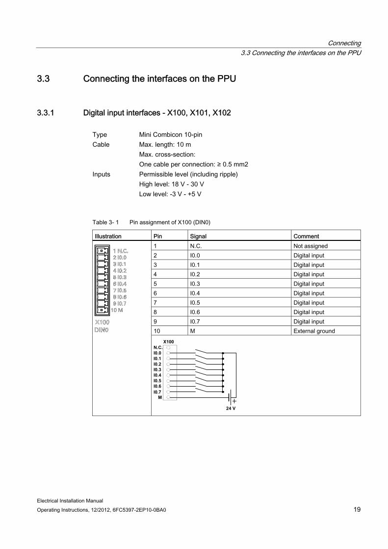
Table 3- 1 Pin assignment of X100 (DIN0)
Illustration Pin Signal Comment 1 N.C. Not assigned 2 I0.0 Digital input 3 I0.1 Digital input 4 I0.2 Digital input 5 I0.3 Digital input 6 I0.4 Digital input 7 I0.5 Digital input 8 I0.6 Digital input 9 I0.7 Digital input 10 M External ground
X100
I0.0N.C.
I0.1I0.2I0.3I0.4I0.5I0.6I0.7
M
24 V
Connecting 3.3 Connecting the interfaces on the PPU
Electrical Installation Manual 20 Operating Instructions, 12/2012, 6FC5397-2EP10-0BA0
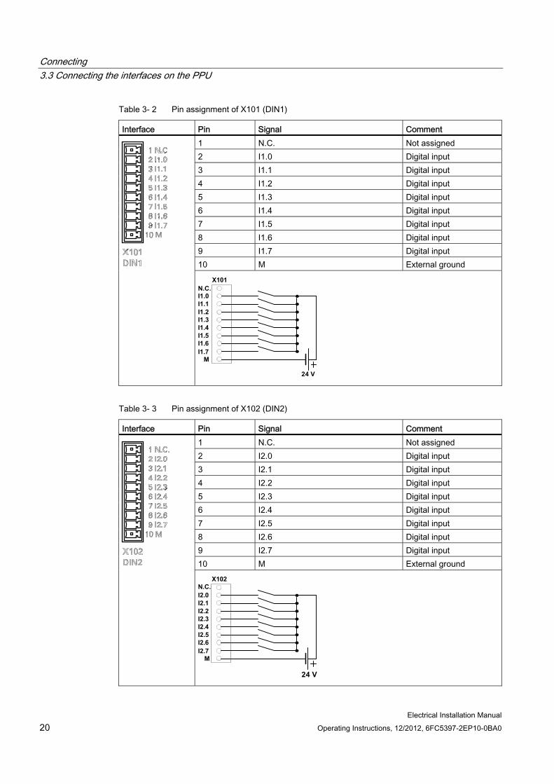
Table 3- 2 Pin assignment of X101 (DIN1)
Interface Pin Signal Comment 1 N.C. Not assigned 2 I1.0 Digital input 3 I1.1 Digital input 4 I1.2 Digital input 5 I1.3 Digital input 6 I1.4 Digital input 7 I1.5 Digital input 8 I1.6 Digital input 9 I1.7 Digital input 10 M External ground
X101
I1.0N.C.
I1.1I1.2I1.3I1.4I1.5I1.6I1.7
M
24 V
Table 3- 3 Pin assignment of X102 (DIN2)
Interface Pin Signal Comment 1 N.C. Not assigned 2 I2.0 Digital input 3 I2.1 Digital input 4 I2.2 Digital input 5 I2.3 Digital input 6 I2.4 Digital input 7 I2.5 Digital input 8 I2.6 Digital input 9 I2.7 Digital input 10 M External ground
I2.0N.C.
I2.1I2.2I2.3I2.4I2.5I2.6I2.7
M
X102
24 V

Connecting 3.3 Connecting the interfaces on the PPU
Electrical Installation Manual Operating Instructions, 12/2012, 6FC5397-2EP10-0BA0 21
Connecting End sleeves are necessary if you use two cables per connection.
Fasten the cables to the screw terminals and plug the terminals into interfaces X100, X101 and X102 correctly.
3.3.2 Digital output interfaces - X200, X201 Type Mini Combicon 10-pin Cable Max. length: 10 m
Max. cross-section: One cable per connection: ≥ 0.5 mm2
Outputs Rated digital output current: 250 mA
Table 3- 4 Pin assignment of X200 (DOUT0)
Illustration Pin Signal Comment 1 +24V +24V input (20.4 - 28.8 V); must be connected 2 Q0.0 Digital output 3 Q0.1 Digital output 4 Q0.2 Digital output 5 Q0.3 Digital output 6 Q0.4 Digital output 7 Q0.5 Digital output 8 Q0.6 Digital output 9 Q0.7 Digital output 10 M External ground; must be connected
X200
Q0.0Q0.1Q0.2Q0.3Q0.4Q0.5Q0.6Q0.7
24 V
M
+24V
Note:
The +24 V power supply must be connected even if X200 is not used; otherwise, the communication between the PPU and the drives does not function as it should.
Connecting 3.3 Connecting the interfaces on the PPU
Electrical Installation Manual 22 Operating Instructions, 12/2012, 6FC5397-2EP10-0BA0
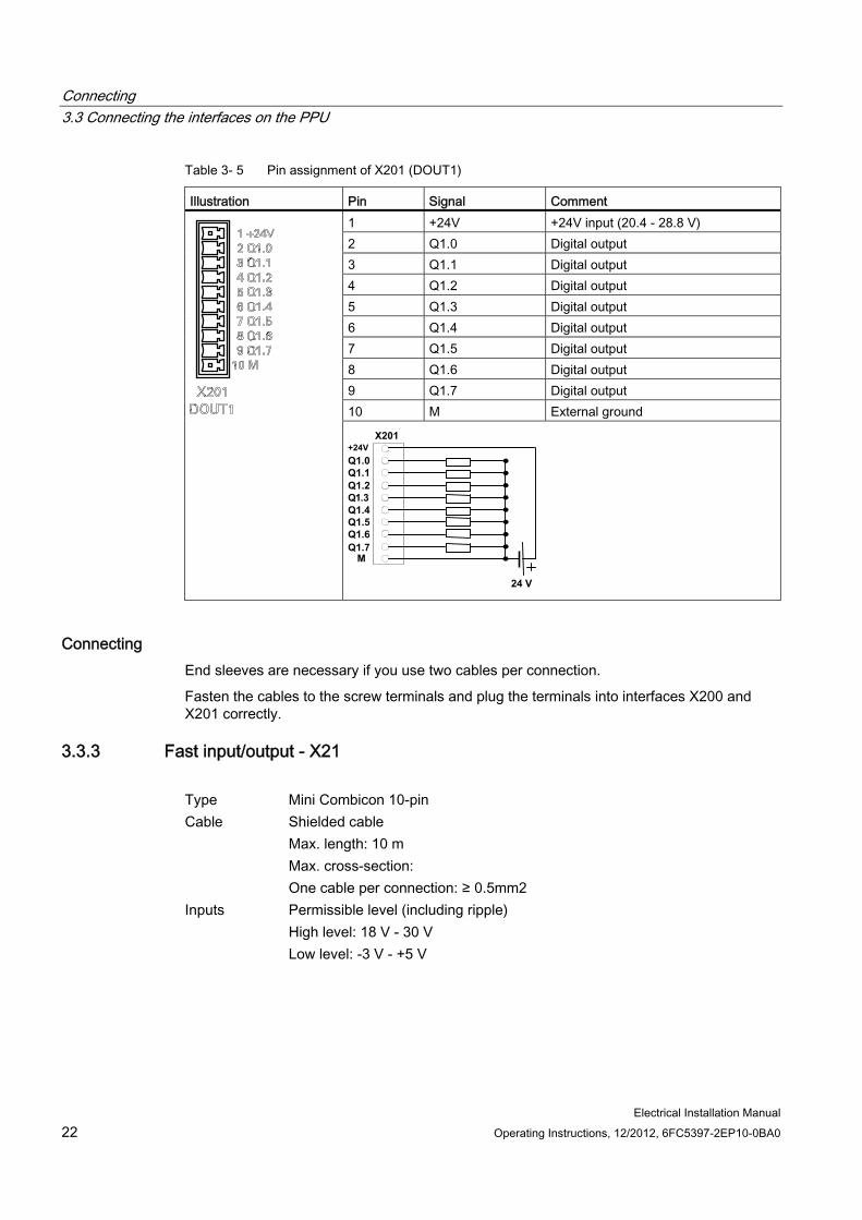
Table 3- 5 Pin assignment of X201 (DOUT1)
Illustration Pin Signal Comment 1 +24V +24V input (20.4 - 28.8 V) 2 Q1.0 Digital output 3 Q1.1 Digital output 4 Q1.2 Digital output 5 Q1.3 Digital output 6 Q1.4 Digital output 7 Q1.5 Digital output 8 Q1.6 Digital output 9 Q1.7 Digital output 10 M External ground
X201
Q1.0Q1.1Q1.2Q1.3Q1.4Q1.5Q1.6Q1.7
M
24 V
+24V
Connecting End sleeves are necessary if you use two cables per connection.
Fasten the cables to the screw terminals and plug the terminals into interfaces X200 and X201 correctly.
3.3.3 Fast input/output - X21 Type Mini Combicon 10-pin Cable Shielded cable
Max. length: 10 m Max. cross-section: One cable per connection: ≥ 0.5mm2
Inputs Permissible level (including ripple) High level: 18 V - 30 V Low level: -3 V - +5 V
Connecting 3.3 Connecting the interfaces on the PPU
Electrical Installation Manual Operating Instructions, 12/2012, 6FC5397-2EP10-0BA0 23
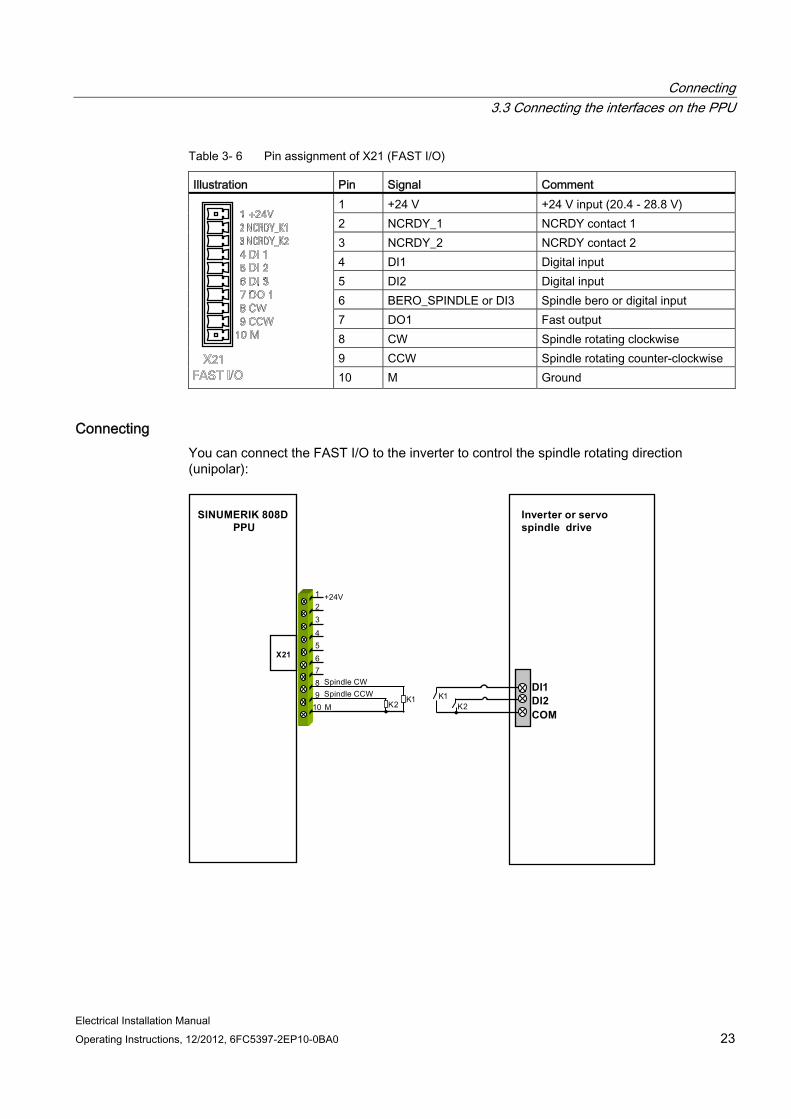
Table 3- 6 Pin assignment of X21 (FAST I/O)
Illustration Pin Signal Comment 1 +24 V +24 V input (20.4 - 28.8 V) 2 NCRDY_1 NCRDY contact 1 3 NCRDY_2 NCRDY contact 2 4 DI1 Digital input 5 DI2 Digital input 6 BERO_SPINDLE or DI3 Spindle bero or digital input 7 DO1 Fast output 8 CW Spindle rotating clockwise 9 CCW Spindle rotating counter-clockwise
10 M Ground
Connecting You can connect the FAST I/O to the inverter to control the spindle rotating direction (unipolar):
Inverter or servo spindle drive
DI1DI2COM
X21
SINUMERIK 808D PPU
Connecting 3.3 Connecting the interfaces on the PPU
Electrical Installation Manual 24 Operating Instructions, 12/2012, 6FC5397-2EP10-0BA0
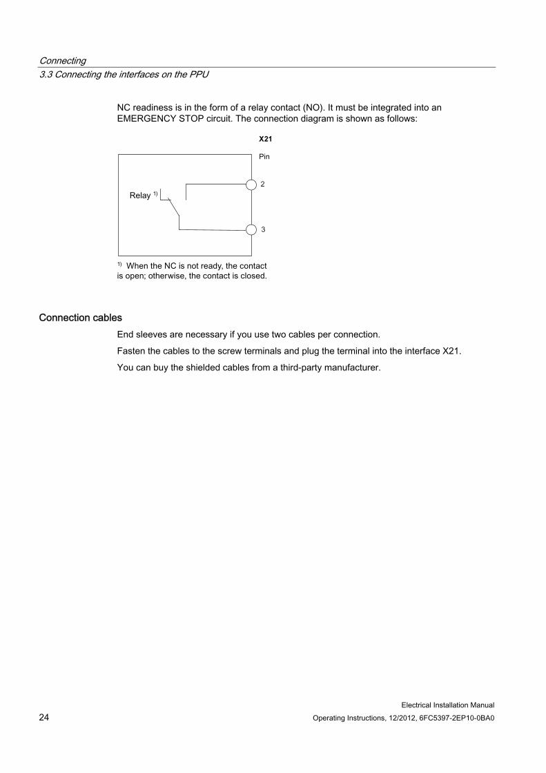
NC readiness is in the form of a relay contact (NO). It must be integrated into an EMERGENCY STOP circuit. The connection diagram is shown as follows:
X21
3
2
Connection cables End sleeves are necessary if you use two cables per connection.
Fasten the cables to the screw terminals and plug the terminal into the interface X21.
You can buy the shielded cables from a third-party manufacturer.
Connecting 3.3 Connecting the interfaces on the PPU
Electrical Installation Manual Operating Instructions, 12/2012, 6FC5397-2EP10-0BA0 25
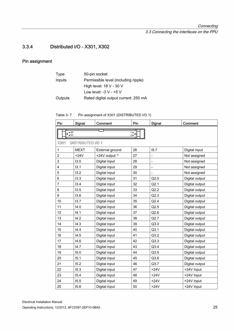
3.3.4 Distributed I/O - X301, X302
Pin assignment Type 50-pin socket Inputs Permissible level (including ripple)
High level: 18 V - 30 V Low level: -3 V - +5 V
Outputs Rated digital output current: 250 mA
Table 3- 7 Pin assignment of X301 (DISTRIBUTED I/O 1)
Pin Signal Comment Pin Signal Comment
1 MEXT External ground 26 I5.7 Digital input 2 +24V +24V output 1) 27 - Not assigned 3 I3.0 Digital input 28 - Not assigned 4 I3.1 Digital input 29 - Not assigned 5 I3.2 Digital input 30 - Not assigned 6 I3.3 Digital input 31 Q2.0 Digital output 7 I3.4 Digital input 32 Q2.1 Digital output 8 I3.5 Digital input 33 Q2.2 Digital output 9 I3.6 Digital input 34 Q2.3 Digital output 10 I3.7 Digital input 35 Q2.4 Digital output 11 I4.0 Digital input 36 Q2.5 Digital output 12 I4.1 Digital input 37 Q2.6 Digital output 13 I4.2 Digital input 38 Q2.7 Digital output 14 I4.3 Digital input 39 Q3.0 Digital output 15 I4.4 Digital input 40 Q3.1 Digital output 16 I4.5 Digital input 41 Q3.2 Digital output 17 I4.6 Digital input 42 Q3.3 Digital output 18 I4.7 Digital input 43 Q3.4 Digital output 19 I5.0 Digital input 44 Q3.5 Digital output 20 I5.1 Digital input 45 Q3.6 Digital output 21 I5.2 Digital input 46 Q3.7 Digital output 22 I5.3 Digital input 47 +24V +24V Input 23 I5.4 Digital input 48 +24V +24V Input 24 I5.5 Digital input 49 +24V +24V Input 25 I5.6 Digital input 50 +24V +24V Input
Connecting 3.3 Connecting the interfaces on the PPU
Electrical Installation Manual 26 Operating Instructions, 12/2012, 6FC5397-2EP10-0BA0
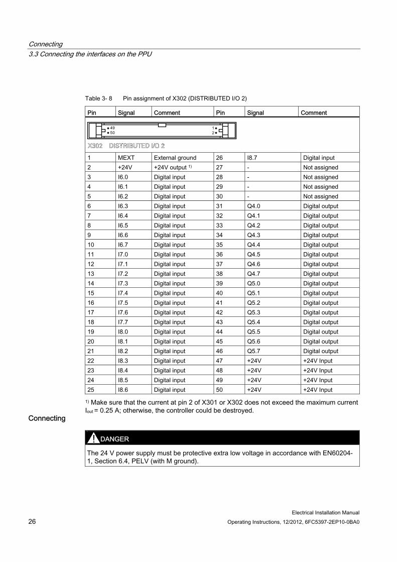
Table 3- 8 Pin assignment of X302 (DISTRIBUTED I/O 2)
Pin Signal Comment Pin Signal Comment
1 MEXT External ground 26 I8.7 Digital input 2 +24V +24V output 1) 27 - Not assigned 3 I6.0 Digital input 28 - Not assigned 4 I6.1 Digital input 29 - Not assigned 5 I6.2 Digital input 30 - Not assigned 6 I6.3 Digital input 31 Q4.0 Digital output 7 I6.4 Digital input 32 Q4.1 Digital output 8 I6.5 Digital input 33 Q4.2 Digital output 9 I6.6 Digital input 34 Q4.3 Digital output 10 I6.7 Digital input 35 Q4.4 Digital output 11 I7.0 Digital input 36 Q4.5 Digital output 12 I7.1 Digital input 37 Q4.6 Digital output 13 I7.2 Digital input 38 Q4.7 Digital output 14 I7.3 Digital input 39 Q5.0 Digital output 15 I7.4 Digital input 40 Q5.1 Digital output 16 I7.5 Digital input 41 Q5.2 Digital output 17 I7.6 Digital input 42 Q5.3 Digital output 18 I7.7 Digital input 43 Q5.4 Digital output 19 I8.0 Digital input 44 Q5.5 Digital output 20 I8.1 Digital input 45 Q5.6 Digital output 21 I8.2 Digital input 46 Q5.7 Digital output 22 I8.3 Digital input 47 +24V +24V Input 23 I8.4 Digital input 48 +24V +24V Input 24 I8.5 Digital input 49 +24V +24V Input 25 I8.6 Digital input 50 +24V +24V Input
1) Make sure that the current at pin 2 of X301 or X302 does not exceed the maximum current Iout = 0.25 A; otherwise, the controller could be destroyed.
Connecting
DANGER The 24 V power supply must be protective extra low voltage in accordance with EN60204-1, Section 6.4, PELV (with M ground).
Connecting 3.3 Connecting the interfaces on the PPU
Electrical Installation Manual Operating Instructions, 12/2012, 6FC5397-2EP10-0BA0 27
CAUTION Be sure not to connect the pin 2 of X301/302 to ground; otherwise, the CNC controller or the power supply could be damaged!
Note
The 24 V output of X301/302 pin 2 comes from pins 47 to 50.
Note Addressing ranges
X301: IB3, IB4, IB5, QB2, QB3
X302: IB6, IB7, IB8, QB4, QB5
Note
The connecting cable between the power source, load current supply connection, and associated reference potential M must not exceed the maximum permissible length of 10 m.
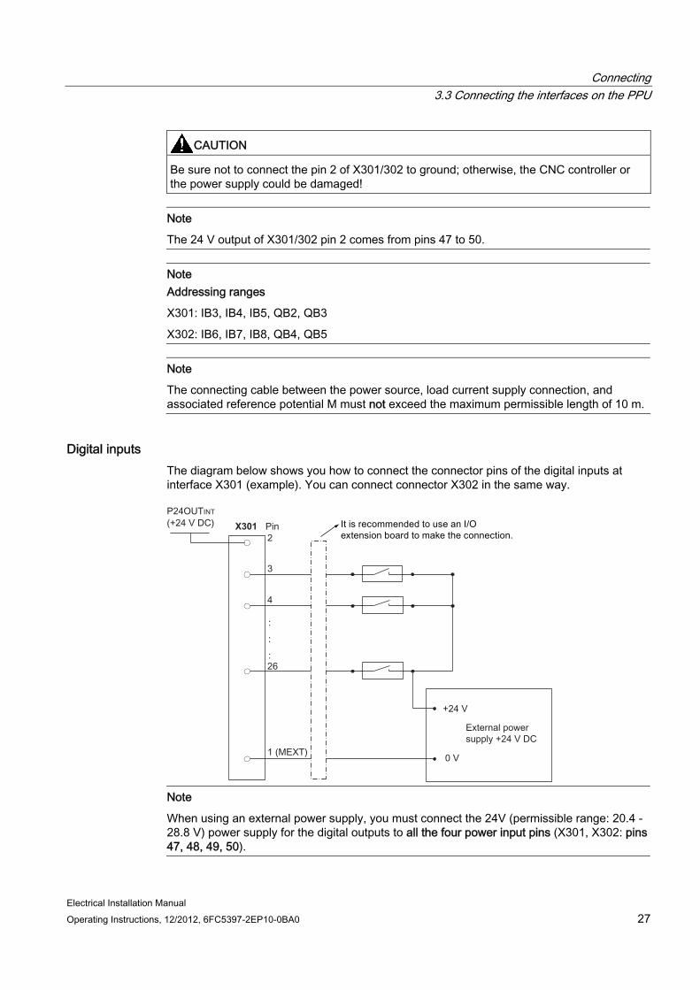
Digital inputs The diagram below shows you how to connect the connector pins of the digital inputs at interface X301 (example). You can connect connector X302 in the same way.
X301
Note
When using an external power supply, you must connect the 24V (permissible range: 20.4 - 28.8 V) power supply for the digital outputs to all the four power input pins (X301, X302: pins 47, 48, 49, 50).
Connecting 3.3 Connecting the interfaces on the PPU
Electrical Installation Manual 28 Operating Instructions, 12/2012, 6FC5397-2EP10-0BA0
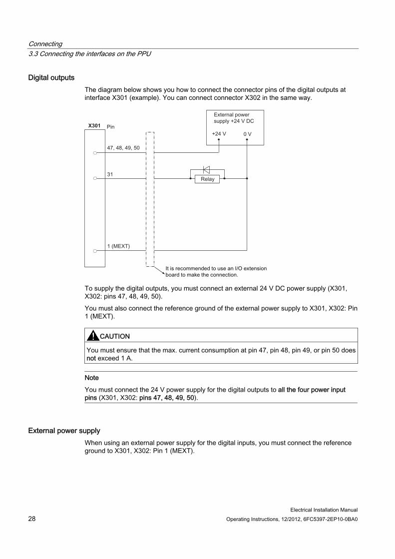
Digital outputs The diagram below shows you how to connect the connector pins of the digital outputs at interface X301 (example). You can connect connector X302 in the same way.
X301
To supply the digital outputs, you must connect an external 24 V DC power supply (X301, X302: pins 47, 48, 49, 50).
You must also connect the reference ground of the external power supply to X301, X302: Pin 1 (MEXT).
CAUTION You must ensure that the max. current consumption at pin 47, pin 48, pin 49, or pin 50 does not exceed 1 A.
Note
You must connect the 24 V power supply for the digital outputs to all the four power input pins (X301, X302: pins 47, 48, 49, 50).
External power supply When using an external power supply for the digital inputs, you must connect the reference ground to X301, X302: Pin 1 (MEXT).
Connecting 3.3 Connecting the interfaces on the PPU
Electrical Installation Manual Operating Instructions, 12/2012, 6FC5397-2EP10-0BA0 29
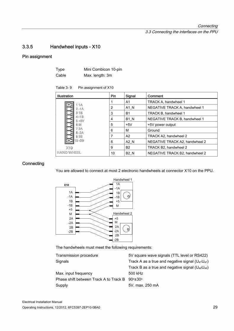
3.3.5 Handwheel inputs - X10
Pin assignment Type Mini Combicon 10-pin Cable Max. length: 3m
Table 3- 9 Pin assignment of X10
Illustration Pin Signal Comment 1 A1 TRACK A, handwheel 1 2 A1_N NEGATIVE TRACK A, handwheel 1 3 B1 TRACK B, handwheel 1 4 B1_N NEGATIVE TRACK B, handwheel 1 5 +5V +5V power output 6 M Ground 7 A2 TRACK A2, handwheel 2 8 A2_N NEGATIVE TRACK A2, handwheel 2 9 B2 TRACK B2, handwheel 2
10 B2_N NEGATIVE TRACK B2, handwheel 2
Connecting You are allowed to connect at most 2 electronic handwheels at connector X10 on the PPU.
X10
The handwheels must meet the following requirements:
Transmission procedure 5V square wave signals (TTL level or RS422) Signals Track A as a true and negative signal (Ua1Ua1)
Track B as a true and negative signal (Ua2Ua2) Max. input frequency 500 kHz Phase shift between Track A to Track B 90o±30o Supply 5V, max. 250 mA

Connecting 3.3 Connecting the interfaces on the PPU
Electrical Installation Manual 30 Operating Instructions, 12/2012, 6FC5397-2EP10-0BA0
3.3.6 Pulse drive interfaces - X51, X52, X53
Pin assignment Type Sub-D, 15-pin, male Cable Type: drive cable
Max. length: 10m
Illustration Pin Signal Comment
1 PULSE+ PULSE, to drive side 2 DIR+ DIRECTION, to drive side 3 ENA+ ENABLE, to drive side 4 BERO Zero mark, from drive side 5 +24V POWER from the pin 1 of X200, +24V output 6 RST ALARM RESET, to drive side 7 M24 Ground 8 +24V POWER from the pin 1 of X200, +24V output 9 PULSE- NEGATIVE PULSE, to drive side 10 DIR- NEGATIVE DIRECTION, to drive side 11 ENA- NEGATIVE ENABLE, to drive side 12 +24V POWER from the pin 1 of X200, +24V output 13 M24 Ground 14 RDY DRIVE READY, from drive side 15 ALM ALARM, from drive side
Note: The +24V and M24 signals at the pulse drive interfaces can only be used when the +24V and M24 pins are connected at the interface X200.
Connecting 3.3 Connecting the interfaces on the PPU
Electrical Installation Manual Operating Instructions, 12/2012, 6FC5397-2EP10-0BA0 31
Connecting
CAUTION Damage to controller or power supply
Pin 5, pin 8 or pin 12 of X51/52/53 are used for +24V power output.
Incorrect connection of them will lead to damage to the CNC controller or the power supply.
Do not connect pin 5, pin 8 or pin 12 of X51/52/53 to ground.
Note
X51/52/53 does not support hot plugging.
Note Filter
A line filter (rated current: 16 A, protection level: IP20) is required so that the system can pass the CE certification (radiated emission test or conducted emission test). The order number of Siemens recommended filter is 6SN1111-0AA01-1BA1.
Note Circuit breaker
You can install a mains linear breaker (rated current: 15 A for 7 A or 10 A version of the drive and 10 A for 4 A or 6 A version of the drive; rated voltage: 250 VAC) to protect the system.
As mentioned before, the SINUMERIK 808D control system can control three axes (X axis, Y axis and Z axis). To do so, you need to connect the control system via the three pulse drive interfaces (X51: X axis, X52: Y axis and X53: Z axis) separately to three SINAMICS V60 drives.
The connection diagram between the SINUMERIK 808D (X51: the X axis) and the SINAMICS V60 is shown as follows. You can connect X52 (the Y axis) and X53 (the Z axis) in the same way.

Connecting 3.3 Connecting the interfaces on the PPU
Electrical Installation Manual 32 Operating Instructions, 12/2012, 6FC5397-2EP10-0BA0
SINUMERIK 808D PPU
SINAMICS V60
The connected motors are SIEMENS 1FL5 servo motors.
For further information about SINAMICS V60 and 1FL5 servo motors, refer to SINUMERIK 808D Mechanical Installation, SINAMICS V60 Getting Started or 1FL5 Motor Data sheet.
See also Analog spindle interface - X54 (Page 33)
Connecting 3.3 Connecting the interfaces on the PPU
Electrical Installation Manual Operating Instructions, 12/2012, 6FC5397-2EP10-0BA0 33
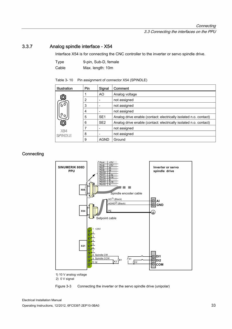
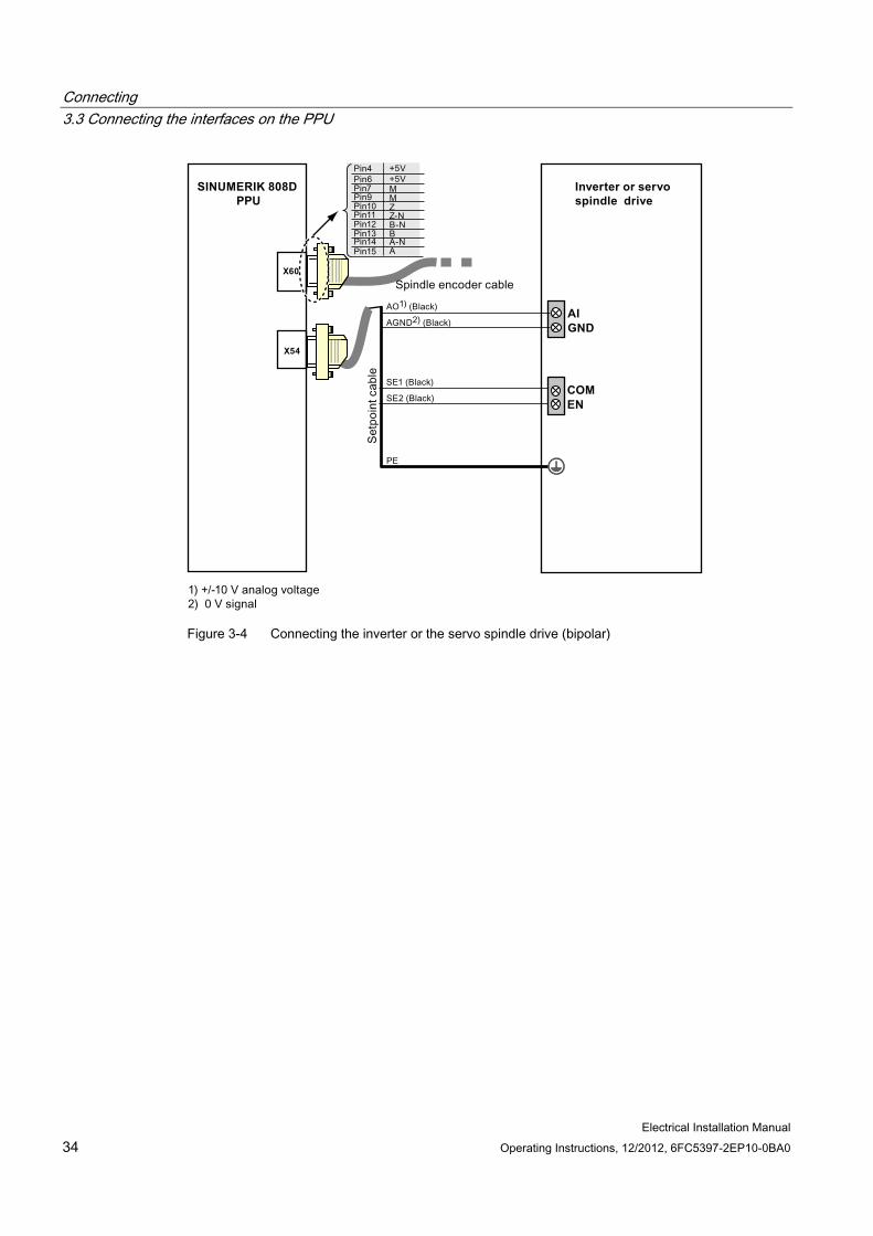
3.3.7 Analog spindle interface - X54 Interface X54 is for connecting the CNC controller to the inverter or servo spindle drive.
Type 9-pin, Sub-D, female Cable Max. length: 10m
Table 3- 10 Pin assignment of connector X54 (SPINDLE)
Illustration Pin Signal Comment 1 AO Analog voltage 2 - not assigned 3 - not assigned 4 - not assigned 5 SE1 Analog drive enable (contact: electrically isolated n.o. contact) 6 SE2 Analog drive enable (contact: electrically isolated n.o. contact) 7 - not assigned 8 - not assigned 9 AGND Ground
Connecting
Inverter or servo spindle drive
AIGND
X54
X60
X21
SINUMERIK 808D PPU
COM
DI1DI2
Figure 3-3 Connecting the inverter or the servo spindle drive (unipolar)
Connecting 3.3 Connecting the interfaces on the PPU
Electrical Installation Manual 34 Operating Instructions, 12/2012, 6FC5397-2EP10-0BA0
Inverter or servo spindle drive
AIGND
COMEN
X54
X60
SINUMERIK 808D PPU
Figure 3-4 Connecting the inverter or the servo spindle drive (bipolar)

Connecting 3.3 Connecting the interfaces on the PPU
Electrical Installation Manual Operating Instructions, 12/2012, 6FC5397-2EP10-0BA0 35
3.3.8 Spindle encoder interface - X60 Type Sub-D, 15-pin, female Cable Type: encoder cable
Max. length: 10m
Table 3- 11 Pin assignment of X60 (SP ENCODER)
Illustration Pin Signal Comment 1 - Not assigned 2 - Not assigned 3 - Not assigned 4 +5V +5 V power supply 5 - Not assigned 6 +5V +5 V power supply 7 M Ground 8 - Not assigned 9 M Ground 10 Z Zero mark 11 Z_N Zero mark, negative 12 B_N Track B, negative 13 B Track B 14 A_N Track A, negative
15 A Track A

Connecting 3.3 Connecting the interfaces on the PPU
Electrical Installation Manual 36 Operating Instructions, 12/2012, 6FC5397-2EP10-0BA0
3.3.9 RS232 interface - X2 You can connect a PC/PG to the SINUMERIK 808D via an RS232 port for communication purposes.
Type Sub-D, 9-pin, male Cable Type: RS232
Max. length: 10m
Table 3- 12 Pin assignment of X2 (RS232)
Illustration Pin Signal name Signal type Comment 1 - - Not assigned 2 RxD I Receive Data 3 TxD O Transmit Data 4 DTR O Data Terminal Ready 5 M VO Ground 6 DSR I Request Set Ready 7 RTS O Request To Send 8 CTS I Clear To Send 9 - - Not assigned
Connecting 3.3 Connecting the interfaces on the PPU
Electrical Installation Manual Operating Instructions, 12/2012, 6FC5397-2EP10-0BA0 37
Connecting Insert the Sub-D sockets into the RS232 interface X2 on the PPU and into the connector on the PG/PC. Lock the connector into position using the knurled screws.
Note
Use only shielded cables twisted in pairs; the shield must be connected to the metal or metalized connector casing on the side of the control system.
The cable set offered as accessories provides maximum interference immunity.
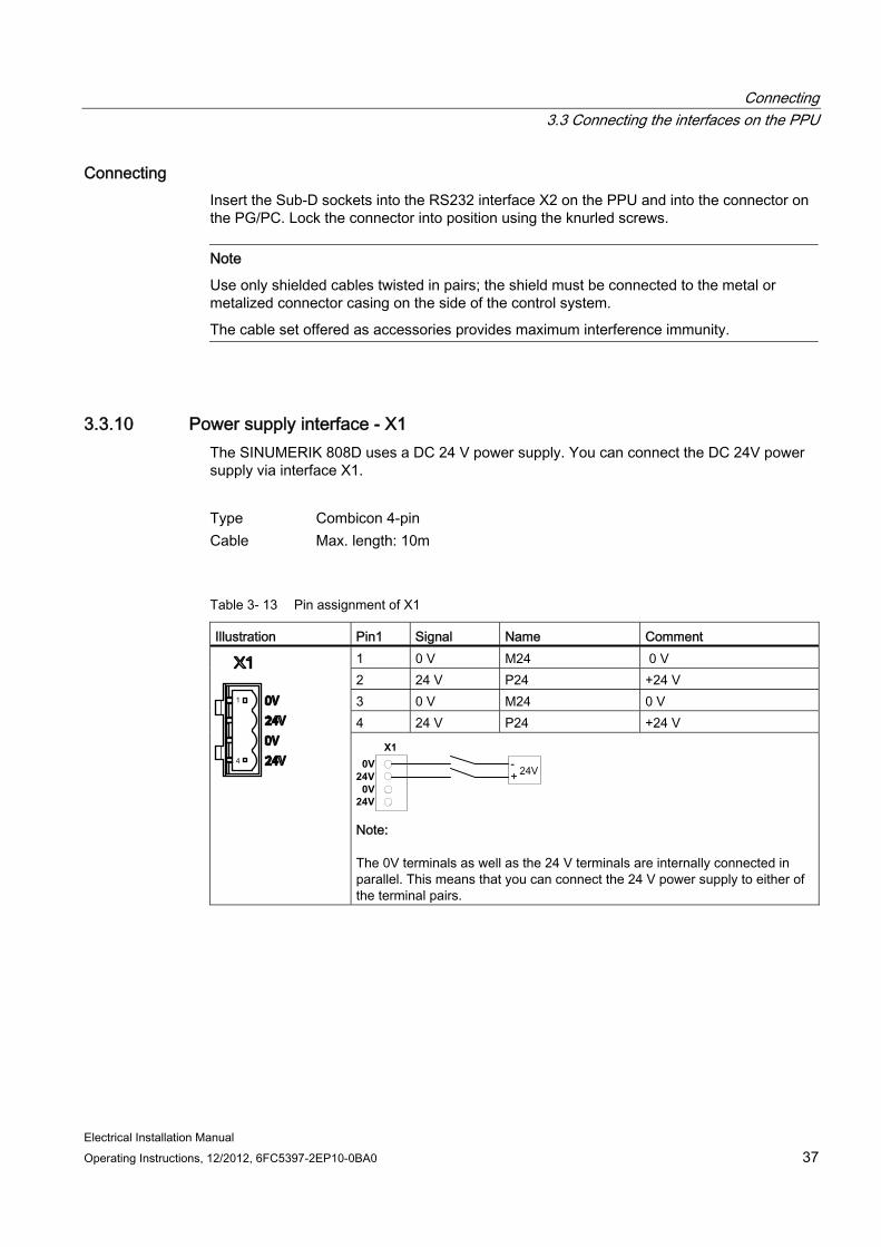
3.3.10 Power supply interface - X1 The SINUMERIK 808D uses a DC 24 V power supply. You can connect the DC 24V power supply via interface X1.
Type Combicon 4-pin Cable Max. length: 10m
Table 3- 13 Pin assignment of X1
Illustration Pin1 Signal Name Comment 1 0 V M24 0 V 2 24 V P24 +24 V 3 0 V M24 0 V 4 24 V P24 +24 V
X10V
24V0V
24V Note:
The 0V terminals as well as the 24 V terminals are internally connected in parallel. This means that you can connect the 24 V power supply to either of the terminal pairs.
Connecting 3.3 Connecting the interfaces on the PPU
Electrical Installation Manual 38 Operating Instructions, 12/2012, 6FC5397-2EP10-0BA0
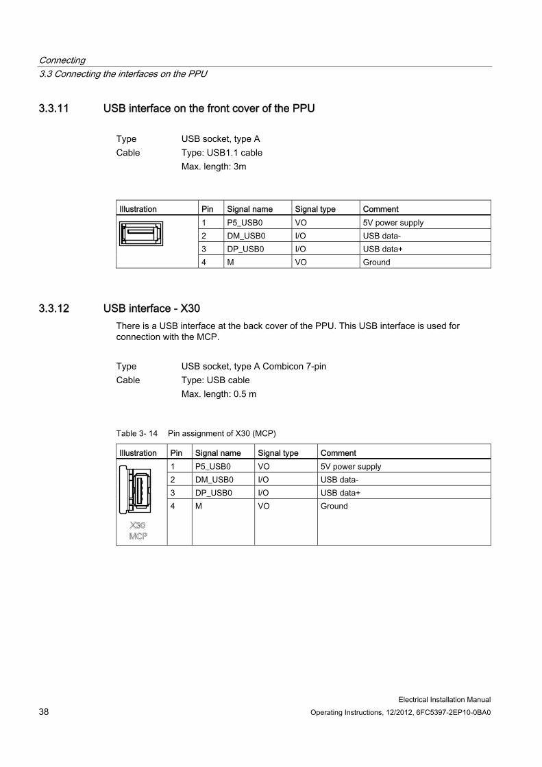
3.3.11 USB interface on the front cover of the PPU Type USB socket, type A Cable Type: USB1.1 cable
Max. length: 3m
Illustration Pin Signal name Signal type Comment
1 P5_USB0 VO 5V power supply 2 DM_USB0 I/O USB data- 3 DP_USB0 I/O USB data+
4 M VO Ground
3.3.12 USB interface - X30 There is a USB interface at the back cover of the PPU. This USB interface is used for connection with the MCP.
Type USB socket, type A Combicon 7-pin Cable Type: USB cable
Max. length: 0.5 m
Table 3- 14 Pin assignment of X30 (MCP)
Illustration Pin Signal name Signal type Comment 1 P5_USB0 VO 5V power supply 2 DM_USB0 I/O USB data- 3 DP_USB0 I/O USB data+
4 M VO Ground
Connecting 3.3 Connecting the interfaces on the PPU
Electrical Installation Manual Operating Instructions, 12/2012, 6FC5397-2EP10-0BA0 39
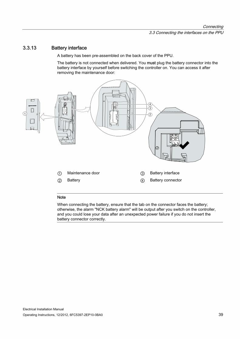
3.3.13 Battery interface A battery has been pre-assembled on the back cover of the PPU.
The battery is not connected when delivered. You must plug the battery connector into the battery interface by yourself before switching the controller on. You can access it after removing the maintenance door:
1 2
34
① Maintenance door ③ Battery interface
② Battery ④ Battery connector
Note
When connecting the battery, ensure that the tab on the connector faces the battery; otherwise, the alarm "NCK battery alarm" will be output after you switch on the controller, and you could lose your data after an unexpected power failure if you do not insert the battery connector correctly.
Connecting 3.4 Connecting the USB interface on the MCP
Electrical Installation Manual 40 Operating Instructions, 12/2012, 6FC5397-2EP10-0BA0
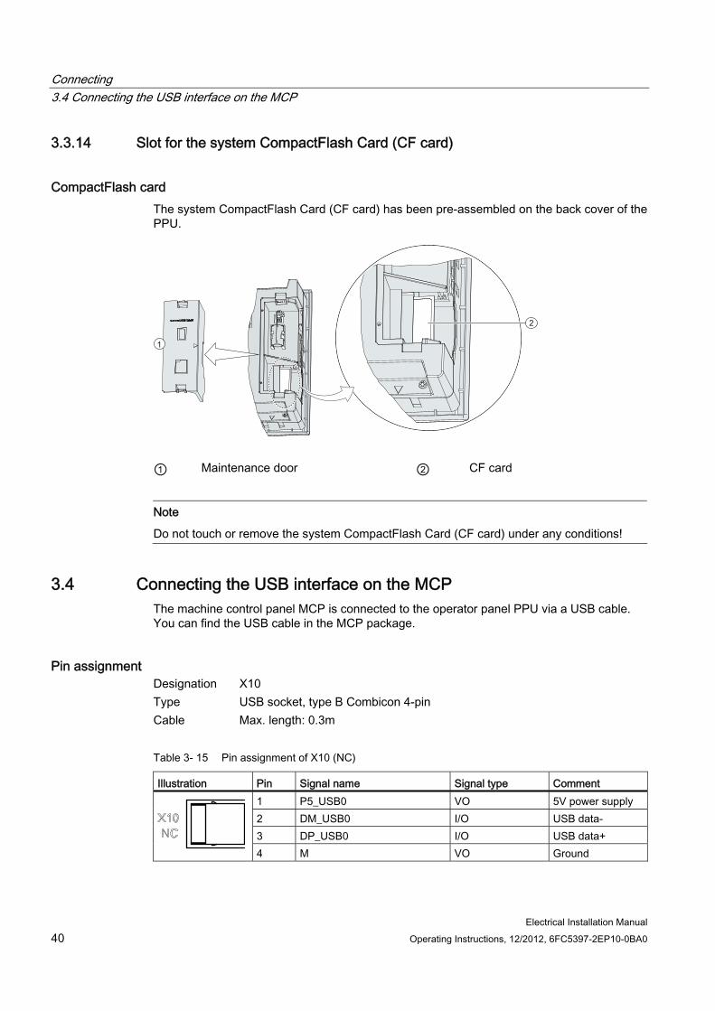
3.3.14 Slot for the system CompactFlash Card (CF card)
CompactFlash card The system CompactFlash Card (CF card) has been pre-assembled on the back cover of the PPU.
1
2
① Maintenance door ② CF card
Note
Do not touch or remove the system CompactFlash Card (CF card) under any conditions!
3.4 Connecting the USB interface on the MCP The machine control panel MCP is connected to the operator panel PPU via a USB cable. You can find the USB cable in the MCP package.
Pin assignment Designation X10 Type USB socket, type B Combicon 4-pin Cable Max. length: 0.3m
Table 3- 15 Pin assignment of X10 (NC)
Illustration Pin Signal name Signal type Comment 1 P5_USB0 VO 5V power supply 2 DM_USB0 I/O USB data- 3 DP_USB0 I/O USB data+
4 M VO Ground
Electrical Installation Manual Operating Instructions, 12/2012, 6FC5397-2EP10-0BA0 41
Technical specifications 4
PPU MCP Design data Dimensions (W x H x D) (in mm) 420 x 200 x 104 420 x 120 x 58 Weight (in kg) 3.06 0.86 Cooling method Self-cooling Self-cooling Degree of protection Front side: IP54
Back side: IP20 Front side: IP54 Back side: IP00
Electrical data Supply voltage 24 V DC (permissible range: 20.4...28.8 V) Ripple 3.6 Vpp 3.6 Vpp Current consumption from 24 V Basic configuration
typically 1.5 A (inputs/outputs open) Non-periodic overvoltage 35 V (500 ms duration, 50 s recovery time) Starting current, total 5 A 5 A Power loss max. 50 W max. 5 W Interference immunity in accordance with EN 61800-3
≥ 20 μs ≥ 20 μs
Overvoltage category 3 3 Degree of pollution 2 2 Transport and storage conditions Temperature -20 °C to +60 °C -20 °C to +60 °C Vibration resistance (transport) 5 Hz~9 Hz: 3.5 mm
9 Hz~200 Hz: 1g 5 Hz~9 Hz: 3.5 mm 9 Hz~200 Hz: 1g
Shock resistance (transport) 10 g peak value, 6 ms duration 100 shocks in each of the 3 axes vertical to one another
Free fall < 1m <1m Relative humidity 5% to 95%, without condensation 5% to 95%, without condensation Atmospheric pressure 1060 hPa to 700 hPa (corresponds to an altitude of 3,000 m) Ambient operating conditions Temperature 0 °C to 45 °C Atmospheric pressure From 1080 hPa to 795 hPa From 1080 hPa to 795 hPa Vibration resistance (in operation) 10 Hz~58 Hz: 0.35 mm
58 Hz~200 Hz: 1g 10 Hz~58 Hz: 0.35 mm 58 Hz~200 Hz: 1g
Shock resistance (in operation) 10 g peak value, 6 ms duration 6 shocks in each of the 3 axes vertical to each other
Lithium battery Rated output voltage 3 V -
Technical specifications 4.1 Radio interference
Electrical Installation Manual 42 Operating Instructions, 12/2012, 6FC5397-2EP10-0BA0
PPU MCP Maximum capacity 950 mAh - Life time 3 years - Certificate CE CE
4.1 Radio interference
Table 4- 1 Limit values for radio interference suppression in industrial environments
Limit class according to EN61800-3 Conducted radio interference C3 Radio interference C3
Note
You must consider interference radiation for the complete system. Particular attention should be paid to cabling. Contact your sales representative for assistance and support.
If compliance with limit value class C2 is required, contact your local Siemens sales partner.
Electrical Installation Manual Operating Instructions, 12/2012, 6FC5397-2EP10-0BA0 43
Appendix AA.1 ESD Directive
A.1.1 What does ESD mean?
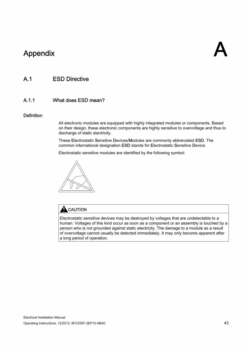
Definition All electronic modules are equipped with highly integrated modules or components. Based on their design, these electronic components are highly sensitive to overvoltage and thus to discharge of static electricity.
These Electrostatic Sensitive Devices/Modules are commonly abbreviated ESD. The common international designation ESD stands for Electrostatic Sensitive Device.
Electrostatic sensitive modules are identified by the following symbol:
CAUTION Electrostatic sensitive devices may be destroyed by voltages that are undetectable to a human. Voltages of this kind occur as soon as a component or an assembly is touched by a person who is not grounded against static electricity. The damage to a module as a result of overvoltage cannot usually be detected immediately. It may only become apparent after a long period of operation.
Appendix A.1 ESD Directive
Electrical Installation Manual 44 Operating Instructions, 12/2012, 6FC5397-2EP10-0BA0
A.1.2 Electrostatic Discharge to Persons
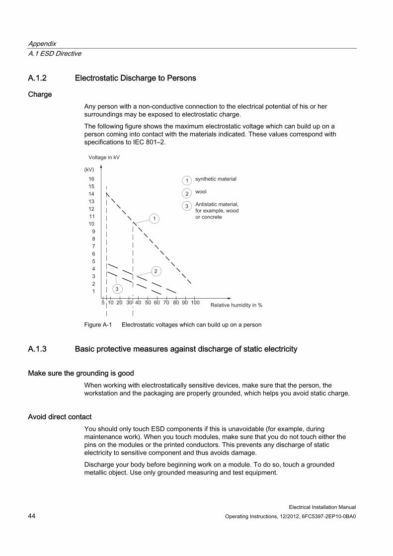
Charge Any person with a non-conductive connection to the electrical potential of his or her surroundings may be exposed to electrostatic charge.
The following figure shows the maximum electrostatic voltage which can build up on a person coming into contact with the materials indicated. These values correspond with specifications to IEC 801–2.
Figure A-1 Electrostatic voltages which can build up on a person
A.1.3 Basic protective measures against discharge of static electricity
Make sure the grounding is good When working with electrostatically sensitive devices, make sure that the person, the workstation and the packaging are properly grounded, which helps you avoid static charge.
Avoid direct contact You should only touch ESD components if this is unavoidable (for example, during maintenance work). When you touch modules, make sure that you do not touch either the pins on the modules or the printed conductors. This prevents any discharge of static electricity to sensitive component and thus avoids damage.
Discharge your body before beginning work on a module. To do so, touch a grounded metallic object. Use only grounded measuring and test equipment.
Appendix A.2 Order numbers
Electrical Installation Manual Operating Instructions, 12/2012, 6FC5397-2EP10-0BA0 45
A.2 Order numbers Product Order number Hardware PPU141.1, turning variant 6FC5370-1AT00-0AA0 (English)
6FC5370-1AT00-0CA0 (Chinese) PPU141.1, milling variant 6FC5370-1AM00-0AA0 (English)
6FC5370-1AM00-0CA0 (Chinese) MCP 6FC5303-0AF35-0AA0 (English)
6FC5303-0AF35-0CA0 (Chinese) Accessories
5 m 6FC5548-0BA00-1AF0 7 m 6FC5548-0BA00-1AH0
Setpoint cable PPU141.1 connected to CPM60.1
10 m 6FC5548-0BA00-1BA0 5 m 6FC5548-0BA05-1AF0 7 m 6FC5548-0BA05-1AH0
Setpoint cable PPU141.1 connected to inverter or servo spindle drive
10 m 6FC5548-0BA05-1BA0 Spare parts Battery 6FC5247-0AA18-0AA0 Options
MM+ (for turning only) 6FC5800-0AP07-0YB0 Additional axis (for turning only) 6FC5800-0AK70-0YB0
Software
Toolbox 6FC5811-0CY00-0YA8 English 6FC5397-2EP10-0BA0 Operating Instructions Chinese 6FC5397-2EP10-0RA0 English 6FC5398-6DP10-0BA0 Diagnostics Manual Chinese 6FC5398-6DP10-0RA0 English 6FC5397-4EP10-0BA0 Commissioning Manual Chinese 6FC5397-4EP10-0RA0 English 6FC5398-5DP10-0BA0 Chinese 6FC5398-5DP10-0RA0 Russian 6FC5398-5DP10-0PA0
Programming and Operating Manual (Turning)
Portuguese 6FC5398-5DP10-0KA0 English 6FC5398-4DP10-0BA0 Chinese 6FC5398-4DP10-0RA0 Russian 6FC5398-4DP10-0PA0
Programming and Operating Manual (Milling)
Portuguese 6FC5398-4DP10-0KA0 English 6FC5398-3DP10-0BA0
Documentation
Manual Machine Plus (Turning) Chinese 6FC5398-3DP10-0RA0
Appendix A.3 FAQs
Electrical Installation Manual 46 Operating Instructions, 12/2012, 6FC5397-2EP10-0BA0
A.3 FAQs FAQ 1 There is no output at the digital output interfaces Answer Check whether you have connected the 24 V DC power supply or not.
Check PLC signals FAQ 2 Black screen Answer Check whether you have correctly connected the 24 V DC power supply or not.
Check whether you have correctly plugged the battery connector or not. Check whether the CF card looses or not.
Electrical Installation Manual Operating Instructions, 12/2012, 6FC5397-2EP10-0BA0 47
Index
C
Connecting Connecting RS232 interface, 37
I Interface
battery interface, 39 X1 (power supply interface), 37 X10 (handwheel inputs), 29 X10 (NC), 40 X100, 19 X101, 20 X102, 20 X2 (RS232), 36 X200, 21 X201, 22 X21, 23 X30 (MCP), 38 X301, 25 X302, 26 X60 (SP ENCODER), 35
Interface overview on the Machine Control Panel (MCP), 16 Interface overview on the Panel Processing Unit (PPU), 15
P
Pin assignment of connector X54 (SPINDLE), 33
S
Safety instructions, 7 System overview, 11

Index
Electrical Installation Manual 48 Operating Instructions, 12/2012, 6FC5397-2EP10-0BA0