single-packaged model 582a gas heating/electric … · pact, fully self-contained, combination gas...
TRANSCRIPT
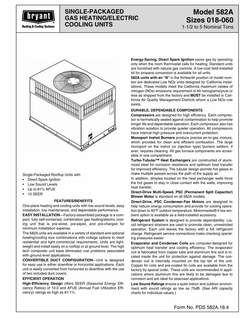
SINGLE-PACKAGEDGAS HEATING/ELECTRICCOOLING UNITS
Model 582A
Sizes 018-060
1-1/2 to 5 Nominal Tons
Form No. PDS 582A.18.4
Single-Packaged Rooftop Units with• Direct Spark Ignition• Low Sound Levels• Up to 81% AFUE• 10 SEER
FEATURES/BENEFITS
One-piece heating and cooling units with low sound levels, easyinstallation, low maintenance, and dependable performance.
EASY INSTALLATION
—Factory-assembled package is a com-pact, fully self-contained, combination gas heating/electric cool-ing unit that is pre-wired, pre-piped, and pre-charged forminimum installation expense.The 582A units are available in a variety of standard and optionalheating/cooling size combinations with voltage options to meetresidential and light commercial requirements. Units are light-weight and install easily on a rooftop or at ground level. The hightech composite unit base eliminates rust problems associatedwith ground level applications.
CONVERTIBLE DUCT CONFIGURATION
—Unit is designedfor easy use in either downflow or horizontal applications. Eachunit is easily converted from horizontal to downflow with the useof two included duct covers.
EFFICIENT OPERATIONHigh-Efficiency Design
offers SEER (Seasonal Energy Effi-ciency Ratios) of 10.0 and AFUE (Annual Fuel Utilization Effi-ciency) ratings as high as 81.1%.
Energy-Saving, Direct Spark Ignition
saves gas by operatingonly when the room thermostat calls for heating. Standard unitsare furnished with natural gas controls. A low-cost field-installedkit for propane conversion is available for all units.
582A units with an “N”
in the thirteenth position of model num-ber are dedicated Low NOx units designed for California instal-lations. These models meet the California maximum oxides ofnitrogen (NOx) emissions requirement of 40 nanograms/joule orless as shipped from the factory and
MUST
be installed in Cali-fornia Air Quality Management Districts where a Low NOx ruleexists.
DURABLE, DEPENDABLE COMPONENTSCompressors
are designed for high efficiency. Each compres-sor is hermetically sealed against contamination to help promotelonger life and dependable operation. Each compressor also hasvibration isolation to provide quieter operation. All compressorshave internal high pressure and overcurrent protection.
Monoport Inshot Burners
produce precise air-to-gas mixture,which provides for clean and efficient combustion. The largemonoport on the inshot (or injection type) burners seldom, ifever, requires cleaning. All gas furnace components are acces-sible in one compartment.
Turbo-Tubular™ Heat Exchangers
are constructed of alumi-nized steel for corrosion resistance and optimum heat transferfor improved efficiency. The tubular design permits hot gases tomake multiple passes across the path of the supply air.In addition, dimples located on the heat exchanger walls forcethe hot gases to stay in close contact with the walls, improvingheat transfer.
Direct-Drive Multi-Speed, PSC (Permanent Split Capacitor)Blower Motor
is standard on all 582A models.
Direct-Drive, PSC Condenser-Fan Motors
are designed tohelp reduce energy consumption and provide for cooling opera-tion down to 40°F outdoor temperature. Motormaster® II low am-bient option is available as a field-installed accessory.
Refrigerant System
is designed to provide dependability. Liq-uid refrigerant strainers are used to promote clean, unrestrictedoperation. Each unit leaves the factory with a full refrigerantcharge. Refrigerant service connections make checking operat-ing pressures easier.
Evaporator and Condenser Coils
are computer-designed foroptimum heat transfer and cooling efficiency. The evaporatorcoil is fabricated from copper tube and aluminum fins and is lo-cated inside the unit for protection against damage. The con-denser coil is internally mounted on the top tier of the unit.Copper fin coils and pre-coated fin coils are available from thefactory by special order. These coils are recommended in appli-cations where aluminum fins are likely to be damaged due tocorrosion and are ideal for seacoast applications.
Low Sound Ratings
ensure a quiet indoor and outdoor environ-ment with sound ratings as low as 75dB. (See ARI capacitycharts for individual values.)
—2—
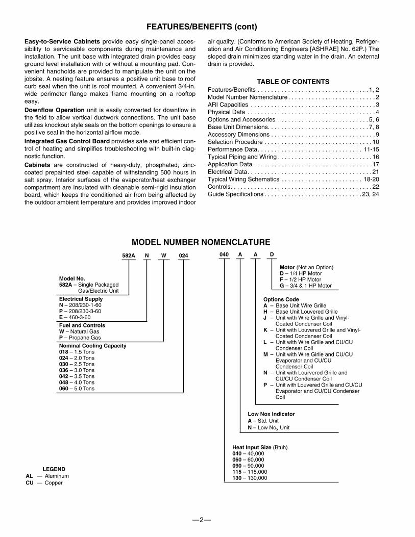
MODEL NUMBER NOMENCLATURE
582A N W 024
Model No.582A
– Single PackagedGas/Electric Unit
Electrical SupplyN
– 208/230-1-60
P
– 208/230-3-60
E
– 460-3-60
Fuel and ControlsW
– Natural Gas
P
– Propane Gas
Nominal Cooling Capacity 018
– 1.5 Tons
024
– 2.0 Tons
030
– 2.5 Tons
036
– 3.0 Tons
042
– 3.5 Tons
048
– 4.0 Tons
060
– 5.0 Tons
Easy-to-Service Cabinets
provide easy single-panel acces-sibility to serviceable components during maintenance andinstallation. The unit base with integrated drain provides easyground level installation with or without a mounting pad. Con-venient handholds are provided to manipulate the unit on thejobsite. A nesting feature ensures a positive unit base to roofcurb seal when the unit is roof mounted. A convenient 3/4-in.wide perimeter flange makes frame mounting on a rooftopeasy.
Downflow Operation
unit is easily converted for downflow inthe field to allow vertical ductwork connections. The unit baseutilizes knockout style seals on the bottom openings to ensure apositive seal in the horizontal airflow mode.
Integrated Gas Control Board
provides safe and efficient con-trol of heating and simplifies troubleshooting with built-in diag-nostic function.
Cabinets
are constructed of heavy-duty, phosphated, zinc-coated prepainted steel capable of withstanding 500 hours insalt spray. Interior surfaces of the evaporator/heat exchangercompartment are insulated with cleanable semi-rigid insulationboard, which keeps the conditioned air from being affected bythe outdoor ambient temperature and provides improved indoor
air quality. (Conforms to American Society of Heating, Refriger-ation and Air Conditioning Engineers [ASHRAE] No. 62P.) Thesloped drain minimizes standing water in the drain. An externaldrain is provided.
TABLE OF CONTENTS
Features/Benefits . . . . . . . . . . . . . . . . . . . . . . . . . . . . . . . . . 1, 2Model Number Nomenclature . . . . . . . . . . . . . . . . . . . . . . . . . . 2ARI Capacities . . . . . . . . . . . . . . . . . . . . . . . . . . . . . . . . . . . . . 3Physical Data . . . . . . . . . . . . . . . . . . . . . . . . . . . . . . . . . . . . . . 4Options and Accessories . . . . . . . . . . . . . . . . . . . . . . . . . . . 5, 6Base Unit Dimensions. . . . . . . . . . . . . . . . . . . . . . . . . . . . . . 7, 8Accessory Dimensions . . . . . . . . . . . . . . . . . . . . . . . . . . . . . . . 9Selection Procedure . . . . . . . . . . . . . . . . . . . . . . . . . . . . . . . . 10Performance Data. . . . . . . . . . . . . . . . . . . . . . . . . . . . . . . 11-15Typical Piping and Wiring . . . . . . . . . . . . . . . . . . . . . . . . . . . . 16Application Data . . . . . . . . . . . . . . . . . . . . . . . . . . . . . . . . . . . 17Electrical Data. . . . . . . . . . . . . . . . . . . . . . . . . . . . . . . . . . . . . 21Typical Wiring Schematics . . . . . . . . . . . . . . . . . . . . . . . . 18-20Controls. . . . . . . . . . . . . . . . . . . . . . . . . . . . . . . . . . . . . . . . . . 22Guide Specifications . . . . . . . . . . . . . . . . . . . . . . . . . . . . . 23, 24
FEATURES/BENEFITS (cont)
040 A A D
Motor
(Not an Option)
D
– 1/4 HP Motor
F
– 1/2 HP Motor
G
– 3/4 & 1 HP Motor
Options(None)
– Wire Grille
AD
– Louvered Grille
BT
– Wire Grille and Vinyl-Coated Condenser Coil Fin
XT
– Louvered Grille and Vinyl-Coated Condenser Coil Fin
CC
– Wie Grille, AL Evaporator and CU/CU Condenser Coil
AC
– Louvered Grille, AL Evapo-rator and CU/CU condenser Coil
AU
– Louvered Grille, CU/CU Evaporator and Condenser Coils
Heat Input Size
(Btuh)
040
– 40,000
060
– 60,000
090
– 90,000
115
– 115,000
130
– 130,000
Options CodeA
– Base Unit Wire Grille
H
– Base Unit Louvered Grille
J
– Unit with Wire Grille and Vinyl-Coated Condenser Coil
K
– Unit with Louvered Grille and Vinyl-Coated Condenser Coil
L
– Unit with Wire Grille and CU/CU Condenser Coil
M
– Unit with Wire Girlle and CU/CU Evaporator and CU/CU Condenser Coil
N
– Unit with Lourvered Grille and CU/CU Condenser Coil
P
– Unit with Louvered Grille and CU/CU Evaporator and CU/CU Condenser Coil
LEGENDAL
— Aluminum
CU
— Copper
Low Nox IndicatorA
– Std. Unit
N
– Low No
x
Unit
—3—
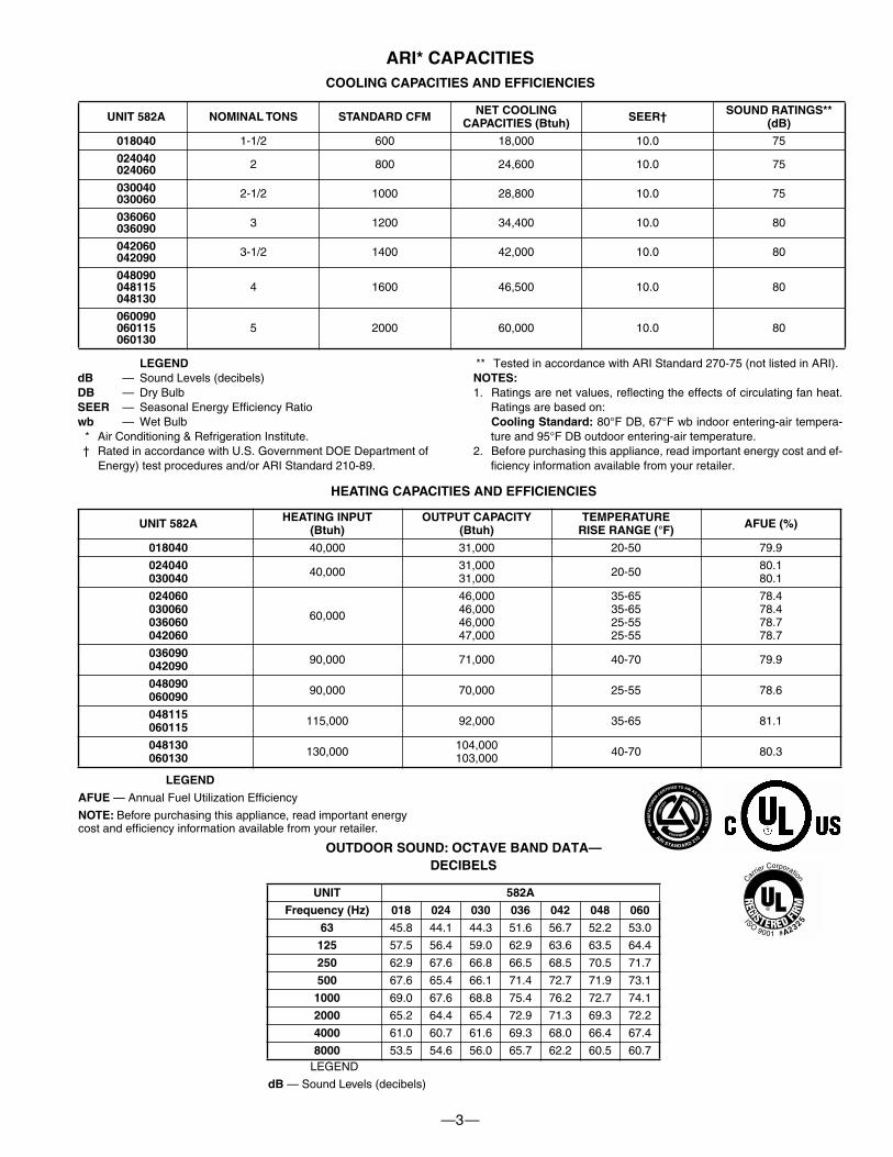
ARI* CAPACITIES
COOLING CAPACITIES AND EFFICIENCIES
UNIT 582A NOMINAL TONS STANDARD CFM NET COOLING CAPACITIES (Btuh) SEER† SOUND RATINGS**
(dB)
018040
1-1/2 600 18,000 10.0 75
024040024060
2 800 24,600 10.0 75
030040030060
2-1/2 1000 28,800 10.0 75
036060036090
3 1200 34,400 10.0 80
042060042090
3-1/2 1400 42,000 10.0 80
048090048115048130
4 1600 46,500 10.0 80
060090060115060130
5 2000 60,000 10.0 80
LEGENDdB
— Sound Levels (decibels)
DB
— Dry Bulb
SEER
— Seasonal Energy Efficiency Ratio
wb
— Wet Bulb* Air Conditioning & Refrigeration Institute.† Rated in accordance with U.S. Government DOE Department of
Energy) test procedures and/or ARI Standard 210-89.
** Tested in accordance with ARI Standard 270-75 (not listed in ARI).
NOTES:
1. Ratings are net values, reflecting the effects of circulating fan heat.Ratings are based on:
Cooling Standard:
80°F DB, 67°F wb indoor entering-air tempera-ture and 95°F DB outdoor entering-air temperature.
2. Before purchasing this appliance, read important energy cost and ef-ficiency information available from your retailer.
HEATING CAPACITIES AND EFFICIENCIES
LEGEND
AFUE
— Annual Fuel Utilization Efficiency
NOTE:
Before purchasing this appliance, read important energy cost and efficiency information available from your retailer.
OUTDOOR SOUND: OCTAVE BAND DATA—DECIBELS
LEGEND
dB
— Sound Levels (decibels)
UNIT 582A HEATING INPUT(Btuh)
OUTPUT CAPACITY(Btuh)
TEMPERATURERISE RANGE (°F) AFUE (%)
018040
40,000 31,000 20-50 79.9
024040030040
40,000 31,00031,000 20-50 80.1
80.1
024060030060036060042060
60,000
46,00046,00046,00047,000
35-6535-6525-5525-55
78.478.478.778.7
036090042090
90,000 71,000 40-70 79.9
048090060090
90,000 70,000 25-55 78.6
048115060115
115,000 92,000 35-65 81.1
048130060130
130,000 104,000103,000 40-70 80.3
UNIT 582A
Frequency (Hz) 018 024 030 036 042 048 060
63
45.8 44.1 44.3 51.6 56.7 52.2 53.0
125
57.5 56.4 59.0 62.9 63.6 63.5 64.4
250
62.9 67.6 66.8 66.5 68.5 70.5 71.7
500
67.6 65.4 66.1 71.4 72.7 71.9 73.1
1000
69.0 67.6 68.8 75.4 76.2 72.7 74.1
2000
65.2 64.4 65.4 72.9 71.3 69.3 72.2
4000
61.0 60.7 61.6 69.3 68.0 66.4 67.4
8000
53.5 54.6 56.0 65.7 62.2 60.5 60.7
32 5
A2
MA
NU
FAC
TUR
ER
CERTIFIED TO ARI AS COMPLY
ING
WITH
ARI STANDARD 210
UN
ITAR
Y
AIR CONDITIO
NIN
G
EQUIPMENT
—4—
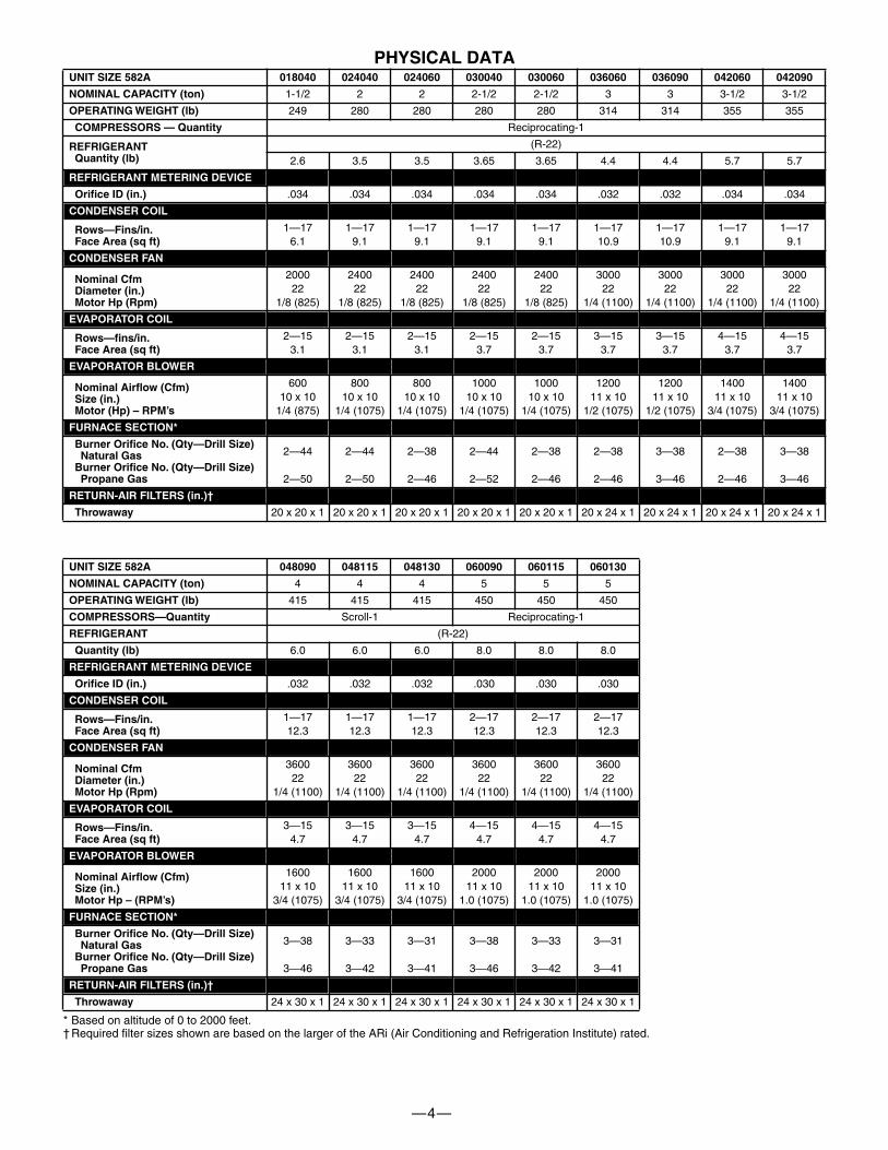
PHYSICAL DATA
* Based on altitude of 0 to 2000 feet.† Required filter sizes shown are based on the larger of the ARi (Air Conditioning and Refrigeration Institute) rated.
UNIT SIZE 582A 018040 024040 024060 030040 030060 036060 036090 042060 042090
NOMINAL CAPACITY (ton)
1-1/2 2 2 2-1/2 2-1/2 3 3 3-1/2 3-1/2
OPERATING WEIGHT (lb)
249 280 280 280 280 314 314 355 355
COMPRESSORS — Quantity
Reciprocating-1
REFRIGERANT Quantity (lb)
(R-22)
2.6 3.5 3.5 3.65 3.65 4.4 4.4 5.7 5.7
REFRIGERANT METERING DEVICE
Orifice ID (in.)
.034 .034 .034 .034 .034 .032 .032 .034 .034
CONDENSER COIL
Rows—Fins/in.Face Area (sq ft)
1—176.1
1—179.1
1—179.1
1—179.1
1—179.1
1—1710.9
1—1710.9
1—179.1
1—179.1
CONDENSER FAN
Nominal CfmDiameter (in.)Motor Hp (Rpm)
200022
1/8 (825)
240022
1/8 (825)
240022
1/8 (825)
240022
1/8 (825)
240022
1/8 (825)
300022
1/4 (1100)
300022
1/4 (1100)
300022
1/4 (1100)
300022
1/4 (1100)
EVAPORATOR COIL
Rows—fins/in.Face Area (sq ft)
2—153.1
2—153.1
2—153.1
2—153.7
2—153.7
3—153.7
3—153.7
4—153.7
4—153.7
EVAPORATOR BLOWER
Nominal Airflow (Cfm)Size (in.)Motor (Hp) – RPM’s
60010 x 10
1/4 (875)
80010 x 10
1/4 (1075)
80010 x 10
1/4 (1075)
100010 x 10
1/4 (1075)
100010 x 10
1/4 (1075)
120011 x 10
1/2 (1075)
120011 x 10
1/2 (1075)
140011 x 10
3/4 (1075)
140011 x 10
3/4 (1075)
FURNACE SECTION*
Burner Orifice No. (Qty—Drill Size)Natural Gas
Burner Orifice No. (Qty—Drill Size)Propane Gas
2—44
2—50
2—44
2—50
2—38
2—46
2—44
2—52
2—38
2—46
2—38
2—46
3—38
3—46
2—38
2—46
3—38
3—46
RETURN-AIR FILTERS (in.)†
Throwaway
20 x 20 x 1 20 x 20 x 1 20 x 20 x 1 20 x 20 x 1 20 x 20 x 1 20 x 24 x 1 20 x 24 x 1 20 x 24 x 1 20 x 24 x 1
UNIT SIZE 582A 048090 048115 048130 060090 060115 060130
NOMINAL CAPACITY (ton)
4 4 4 5 5 5
OPERATING WEIGHT (lb)
415 415 415 450 450 450
COMPRESSORS—Quantity
Scroll-1 Reciprocating-1
REFRIGERANT
(R-22)
Quantity (lb)
6.0 6.0 6.0 8.0 8.0 8.0
REFRIGERANT METERING DEVICE
Orifice ID (in.)
.032 .032 .032 .030 .030 .030
CONDENSER COIL
Rows—Fins/in.Face Area (sq ft)
1—1712.3
1—1712.3
1—1712.3
2—1712.3
2—1712.3
2—1712.3
CONDENSER FAN
Nominal CfmDiameter (in.)Motor Hp (Rpm)
360022
1/4 (1100)
360022
1/4 (1100)
360022
1/4 (1100)
360022
1/4 (1100)
360022
1/4 (1100)
360022
1/4 (1100)
EVAPORATOR COIL
Rows—Fins/in.Face Area (sq ft)
3—154.7
3—154.7
3—154.7
4—154.7
4—154.7
4—154.7
EVAPORATOR BLOWER
Nominal Airflow (Cfm)Size (in.)Motor Hp – (RPM’s)
160011 x 10
3/4 (1075)
160011 x 10
3/4 (1075)
160011 x 10
3/4 (1075)
200011 x 10
1.0 (1075)
200011 x 10
1.0 (1075)
200011 x 10
1.0 (1075)
FURNACE SECTION*
Burner Orifice No. (Qty—Drill Size)Natural Gas
Burner Orifice No. (Qty—Drill Size)Propane Gas
3—38
3—46
3—33
3—42
3—31
3—41
3—38
3—46
3—33
3—42
3—31
3—41
RETURN-AIR FILTERS (in.)†
Throwaway
24 x 30 x 1 24 x 30 x 1 24 x 30 x 1 24 x 30 x 1 24 x 30 x 1 24 x 30 x 1
—5—
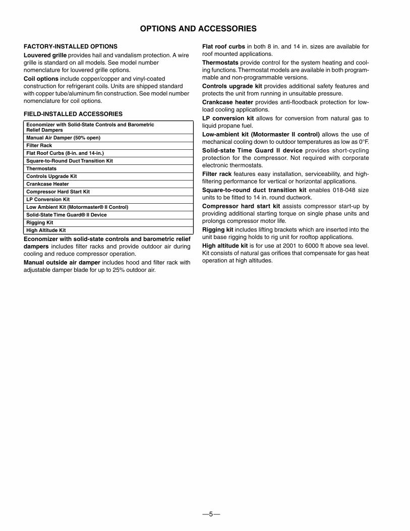
FACTORY-INSTALLED OPTIONSLouvered grille
provides hail and vandalism protection. A wire grille is standard on all models. See model number nomenclature for louvered grille options.
Coil options
include copper/copper and vinyl-coated construction for refrigerant coils. Units are shipped standard with copper tube/aluminum fin construction. See model number nomenclature for coil options.
FIELD-INSTALLED ACCESSORIES
Economizer with solid-state controls and barometric reliefdampers
includes filter racks and provide outdoor air duringcooling and reduce compressor operation.
Manual outside air damper
includes hood and filter rack withadjustable damper blade for up to 25% outdoor air.
Flat roof curbs
in both 8 in. and 14 in. sizes are available forroof mounted applications.
Thermostats
provide control for the system heating and cool-ing functions. Thermostat models are available in both program-mable and non-programmable versions.
Controls upgrade kit
provides additional safety features andprotects the unit from running in unsuitable pressure.
Crankcase heater
provides anti-floodback protection for low-load cooling applications.
LP conversion kit
allows for conversion from natural gas toliquid propane fuel.
Low-ambient kit (Motormaster II control)
allows the use ofmechanical cooling down to outdoor temperatures as low as 0°F.
Solid-state Time Guard II device
provides short-cyclingprotection for the compressor. Not required with corporateelectronic thermostats.
Filter rack
features easy installation, serviceability, and high-filtering performance for vertical or horizontal applications.
Square-to-round duct transition kit
enables 018-048 sizeunits to be fitted to 14 in. round ductwork.
Compressor hard start kit
assists compressor start-up byproviding additional starting torque on single phase units andprolongs compressor motor life.
Rigging kit
includes lifting brackets which are inserted into theunit base rigging holds to rig unit for rooftop applications.
High altitude kit
is for use at 2001 to 6000 ft above sea level.Kit consists of natural gas orifices that compensate for gas heatoperation at high altitudes.
Economizer with Solid-State Controls and BarometricRelief Dampers
Manual Air Damper (50% open)
Filter Rack
Flat Roof Curbs (8-in. and 14-in.)
Square-to-Round Duct Transition Kit
Thermostats
Controls Upgrade Kit
Crankcase Heater
Compressor Hard Start Kit
LP Conversion Kit
Low Ambient Kit (Motormaster® II Control)
Solid-State Time Guard® II Device
Rigging Kit
High Altitude Kit
OPTIONS AND ACCESSORIES
—6—
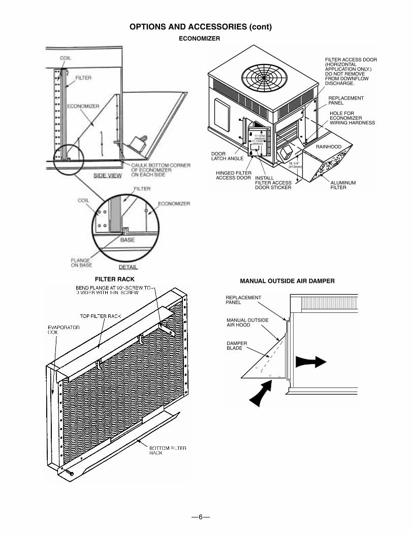
OPTIONS AND ACCESSORIES (cont)
FILTER ACCESS DOOR(HORIZONTALAPPLICATION ONLY.)DO NOT REMOVEFROM DOWNFLOWDISCHARGE.
REPLACEMENTPANEL
HOLE FORECONOMIZERWIRING HARDNESS
DOORLATCH ANGLE
HINGED FILTERACCESS DOOR INSTALL
FILTER ACCESSDOOR STICKER
ALUMINUMFILTER
RAINHOOD
17 13/32(442mm)
16 1/4”(413mm)
11 13/32”(290mm)
FILTER RACK
DAMPERBLADE
MANUAL OUTSIDEAIR HOOD
REPLACEMENTPANEL
MANUAL OUTSIDE AIR DAMPER
ECONOMIZER
—7—
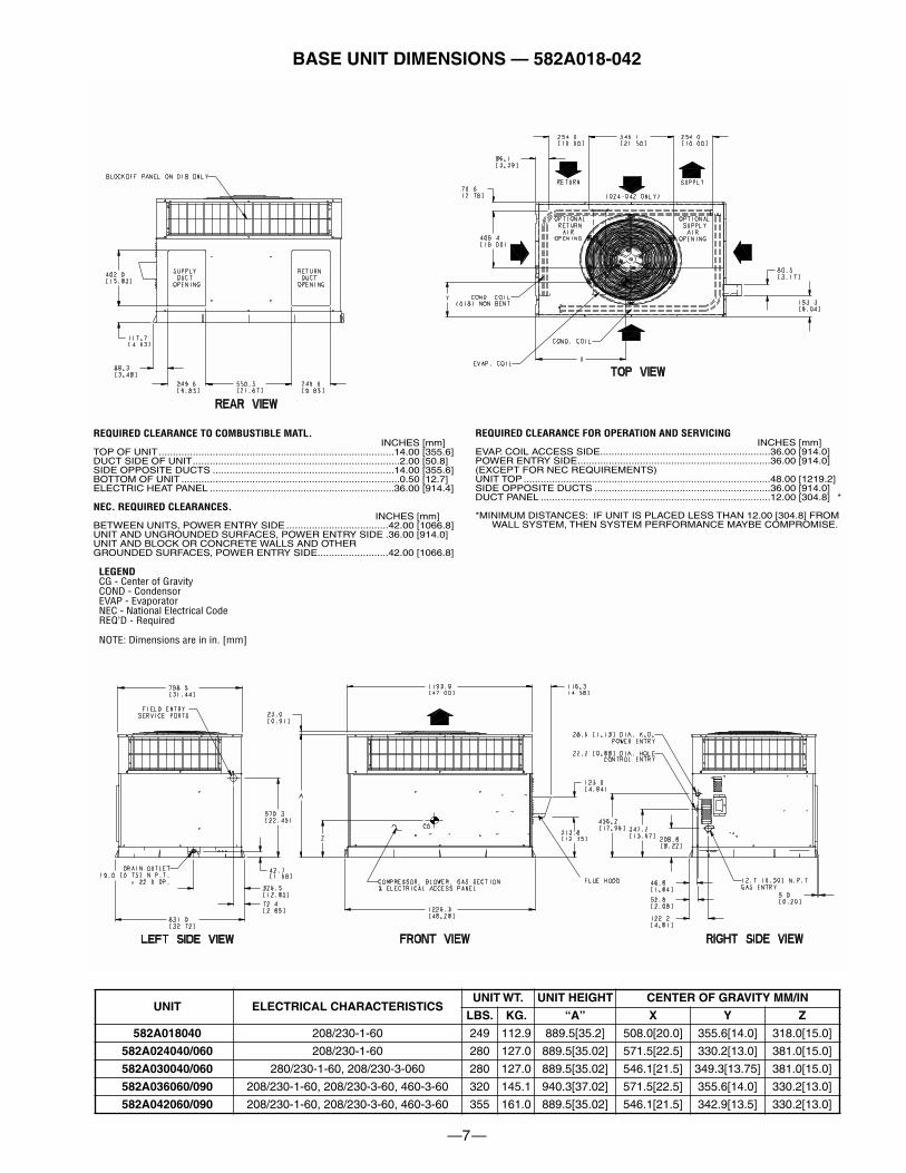
BASE UNIT DIMENSIONS — 582A018-042
UNIT ELECTRICAL CHARACTERISTICSUNIT WT. UNIT HEIGHT CENTER OF GRAVITY MM/IN
LBS. KG. “A” X Y Z
582A018040
208/230-1-60 249 112.9 889.5[35.2] 508.0[20.0] 355.6[14.0] 318.0[15.0]
582A024040/060
208/230-1-60 280 127.0 889.5[35.02] 571.5[22.5] 330.2[13.0] 381.0[15.0]
582A030040/060
280/230-1-60, 208/230-3-060 280 127.0 889.5[35.02] 546.1[21.5] 349.3[13.75] 381.0[15.0]
582A036060/090
208/230-1-60, 208/230-3-60, 460-3-60 320 145.1 940.3[37.02] 571.5[22.5] 355.6[14.0] 330.2[13.0]
582A042060/090
208/230-1-60, 208/230-3-60, 460-3-60 355 161.0 889.5[35.02] 546.1[21.5] 342.9[13.5] 330.2[13.0]
REQUIRED CLEARANCE FOR OPERATION AND SERVICINGINCHES [mm]
EVAP. COIL ACCESS SIDE............................................................36.00 [914.0]POWER ENTRY SIDE....................................................................36.00 [914.0](EXCEPT FOR NEC REQUIREMENTS)UNIT TOP .......................................................................................48.00 [1219.2]SIDE OPPOSITE DUCTS ..............................................................36.00 [914.0]DUCT PANEL .................................................................................12.00 [304.8] *
*MINIMUM DISTANCES: IF UNIT IS PLACED LESS THAN 12.00 [304.8] FROM WALL SYSTEM, THEN SYSTEM PERFORMANCE MAYBE COMPROMISE.
REQUIRED CLEARANCE TO COMBUSTIBLE MATL.INCHES [mm]
TOP OF UNIT...................................................................................14.00 [355.6]DUCT SIDE OF UNIT.........................................................................2.00 [50.8]SIDE OPPOSITE DUCTS ................................................................14.00 [355.6]BOTTOM OF UNIT .............................................................................0.50 [12.7]ELECTRIC HEAT PANEL .................................................................36.00 [914.4]
NEC. REQUIRED CLEARANCES.INCHES [mm]
BETWEEN UNITS, POWER ENTRY SIDE ....................................42.00 [1066.8]UNIT AND UNGROUNDED SURFACES, POWER ENTRY SIDE .36.00 [914.0]UNIT AND BLOCK OR CONCRETE WALLS AND OTHERGROUNDED SURFACES, POWER ENTRY SIDE.........................42.00 [1066.8]
LEGENDCG - Center of GravityCOND - CondensorEVAP - EvaporatorNEC - National Electrical CodeREQ’D - Required
NOTE: Dimensions are in in. [mm]
—8—
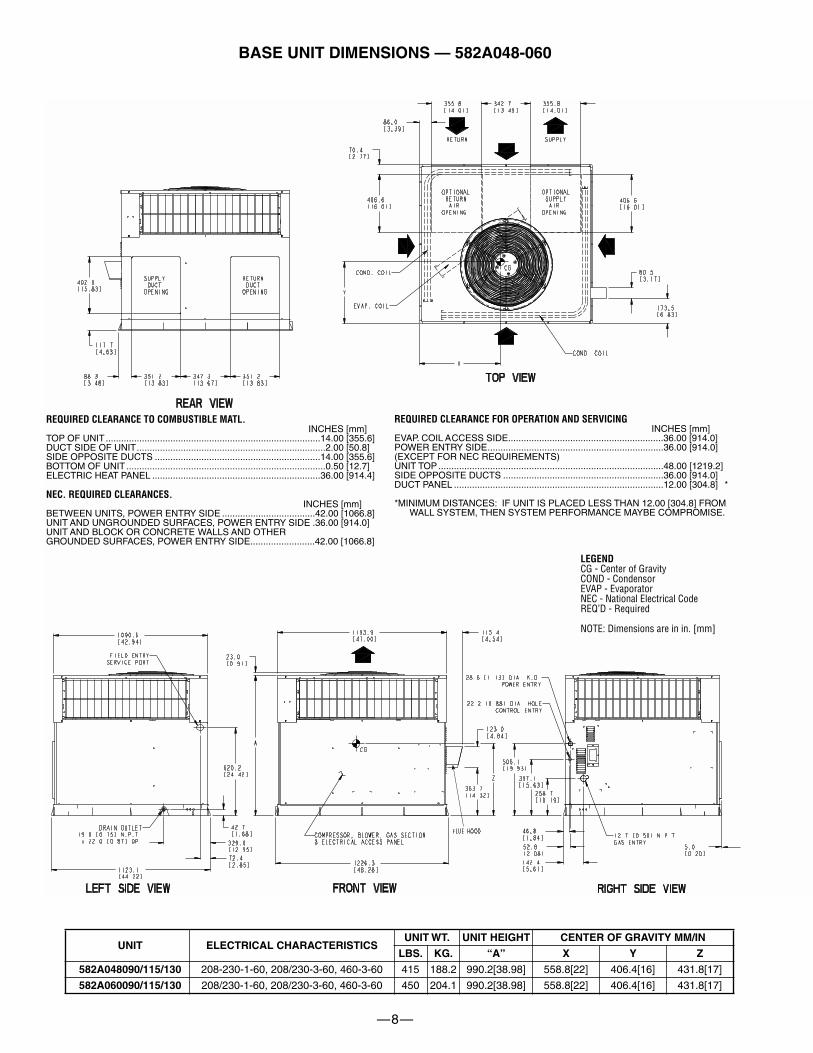
BASE UNIT DIMENSIONS — 582A048-060
UNIT ELECTRICAL CHARACTERISTICSUNIT WT. UNIT HEIGHT CENTER OF GRAVITY MM/IN
LBS. KG. “A” X Y Z
582A048090/115/130
208-230-1-60, 208/230-3-60, 460-3-60 415 188.2 990.2[38.98] 558.8[22] 406.4[16] 431.8[17]
582A060090/115/130
208/230-1-60, 208/230-3-60, 460-3-60 450 204.1 990.2[38.98] 558.8[22] 406.4[16] 431.8[17]
REQUIRED CLEARANCE FOR OPERATION AND SERVICINGINCHES [mm]
EVAP. COIL ACCESS SIDE............................................................36.00 [914.0]POWER ENTRY SIDE....................................................................36.00 [914.0](EXCEPT FOR NEC REQUIREMENTS)UNIT TOP .......................................................................................48.00 [1219.2]SIDE OPPOSITE DUCTS ..............................................................36.00 [914.0]DUCT PANEL .................................................................................12.00 [304.8] *
*MINIMUM DISTANCES: IF UNIT IS PLACED LESS THAN 12.00 [304.8] FROM WALL SYSTEM, THEN SYSTEM PERFORMANCE MAYBE COMPROMISE.
REQUIRED CLEARANCE TO COMBUSTIBLE MATL.INCHES [mm]
TOP OF UNIT...................................................................................14.00 [355.6]DUCT SIDE OF UNIT.........................................................................2.00 [50.8]SIDE OPPOSITE DUCTS ................................................................14.00 [355.6]BOTTOM OF UNIT .............................................................................0.50 [12.7]ELECTRIC HEAT PANEL .................................................................36.00 [914.4]
NEC. REQUIRED CLEARANCES.INCHES [mm]
BETWEEN UNITS, POWER ENTRY SIDE ....................................42.00 [1066.8]UNIT AND UNGROUNDED SURFACES, POWER ENTRY SIDE .36.00 [914.0]UNIT AND BLOCK OR CONCRETE WALLS AND OTHERGROUNDED SURFACES, POWER ENTRY SIDE.........................42.00 [1066.8]
LEGENDCG - Center of GravityCOND - CondensorEVAP - EvaporatorNEC - National Electrical CodeREQ’D - Required
NOTE: Dimensions are in in. [mm]
—9—
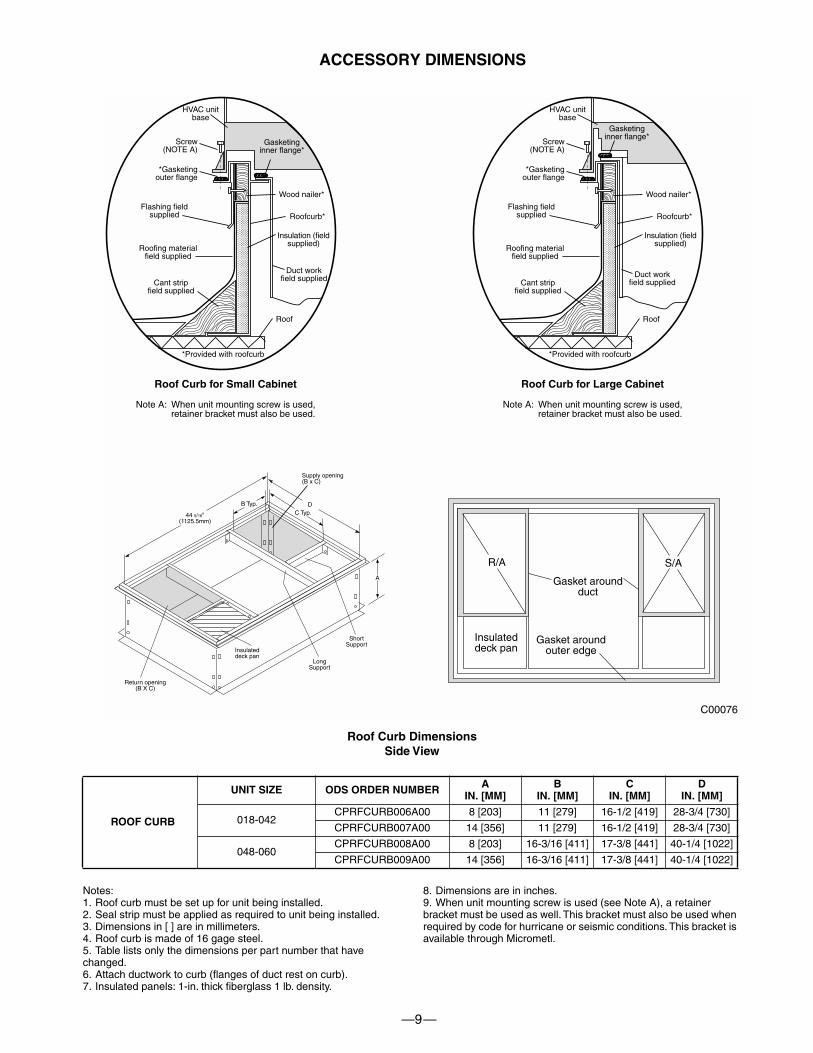
Roof Curb DimensionsSide View
ROOF CURB
UNIT SIZE ODS ORDER NUMBER AIN. [MM]
BIN. [MM]
CIN. [MM]
DIN. [MM]
018-042CPRFCURB006A00 8 [203] 11 [279] 16-1/2 [419] 28-3/4 [730]
CPRFCURB007A00 14 [356] 11 [279] 16-1/2 [419] 28-3/4 [730]
048-060CPRFCURB008A00 8 [203] 16-3/16 [411] 17-3/8 [441] 40-1/4 [1022]
CPRFCURB009A00 14 [356] 16-3/16 [411] 17-3/8 [441] 40-1/4 [1022]
Notes:1. Roof curb must be set up for unit being installed.2. Seal strip must be applied as required to unit being installed.3. Dimensions in [ ] are in millimeters.4. Roof curb is made of 16 gage steel.5. Table lists only the dimensions per part number that have changed.6. Attach ductwork to curb (flanges of duct rest on curb).7. Insulated panels: 1-in. thick fiberglass 1 lb. density.
8. Dimensions are in inches.9. When unit mounting screw is used (see Note A), a retainer bracket must be used as well. This bracket must also be used when required by code for hurricane or seismic conditions. This bracket is available through Micrometl.
C00076
Gasket aroundouter edge
Insulateddeck pan
Gasket aroundduct
S/AR/A
HVAC unitbase
*Gasketingouter flange
Flashing fieldsupplied
Roofing materialfield supplied
Cant stripfield supplied
*Provided with roofcurb
Roof
Duct workfield supplied
Insulation (fieldsupplied)
Roofcurb*
Wood nailer*
Gasketinginner flange*
Screw(NOTE A)
Roof Curb for Small Cabinet
Note A: When unit mounting screw is used,retainer bracket must also be used.
HVAC unitbase
*Gasketingouter flange
Flashing fieldsupplied
Roofing materialfield supplied
Cant stripfield supplied
*Provided with roofcurb
Roof
Duct workfield supplied
Insulation (fieldsupplied)
Roofcurb*
Wood nailer*
Gasketinginner flange*
Screw(NOTE A)
Roof Curb for Large Cabinet
Note A: When unit mounting screw is used,retainer bracket must also be used.
A
B Typ.
Supply opening(B x C)
LongSupport
D
44 5/16"(1125.5mm)
Return opening(B X C)
Insulateddeck pan
ShortSupport
C Typ.
ACCESSORY DIMENSIONS
—10—
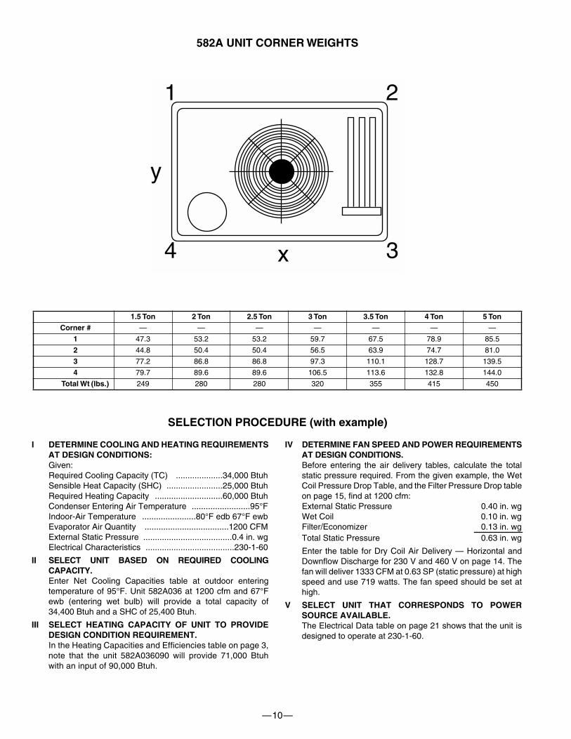
582A UNIT CORNER WEIGHTS
I DETERMINE COOLING AND HEATING REQUIREMENTSAT DESIGN CONDITIONS:
Given:Required Cooling Capacity (TC) ....................34,000 BtuhSensible Heat Capacity (SHC) ........................25,000 BtuhRequired Heating Capacity .............................60,000 BtuhCondenser Entering Air Temperature .........................95°FIndoor-Air Temperature .......................80°F edb 67°F ewbEvaporator Air Quantity ....................................1200 CFMExternal Static Pressure ......................................0.4 in. wgElectrical Characteristics ......................................230-1-60
II SELECT UNIT BASED ON REQUIRED COOLINGCAPACITY.
Enter Net Cooling Capacities table at outdoor enteringtemperature of 95°F. Unit 582A036 at 1200 cfm and 67°Fewb (entering wet bulb) will provide a total capacity of34,400 Btuh and a SHC of 25,400 Btuh.
III SELECT HEATING CAPACITY OF UNIT TO PROVIDEDESIGN CONDITION REQUIREMENT.
In the Heating Capacities and Efficiencies table on page 3,note that the unit 582A036090 will provide 71,000 Btuhwith an input of 90,000 Btuh.
IV DETERMINE FAN SPEED AND POWER REQUIREMENTSAT DESIGN CONDITIONS.
Before entering the air delivery tables, calculate the totalstatic pressure required. From the given example, the WetCoil Pressure Drop Table, and the Filter Pressure Drop tableon page 15, find at 1200 cfm:External Static Pressure 0.40 in. wgWet Coil 0.10 in. wgFilter/Economizer 0.13 in. wgTotal Static Pressure 0.63 in. wg
Enter the table for Dry Coil Air Delivery — Horizontal andDownflow Discharge for 230 V and 460 V on page 14. Thefan will deliver 1333 CFM at 0.63 SP (static pressure) at highspeed and use 719 watts. The fan speed should be set athigh.
V SELECT UNIT THAT CORRESPONDS TO POWERSOURCE AVAILABLE.
The Electrical Data table on page 21 shows that the unit isdesigned to operate at 230-1-60.
1.5 Ton 2 Ton 2.5 Ton 3 Ton 3.5 Ton 4 Ton 5 Ton
Corner #
— — — — — — —
1
47.3 53.2 53.2 59.7 67.5 78.9 85.5
2
44.8 50.4 50.4 56.5 63.9 74.7 81.0
3
77.2 86.8 86.8 97.3 110.1 128.7 139.5
4
79.7 89.6 89.6 106.5 113.6 132.8 144.0
Total Wt (lbs.)
249 280 280 320 355 415 450
1 2
4 3x
y
SELECTION PROCEDURE (with example)
—11—
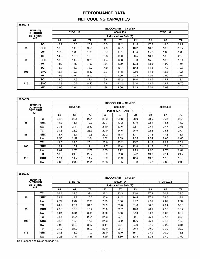
PERFORMANCE DATA
NET COOLING CAPACITIES
See Legend and Notes on page 13.
582A018
TEMP (F)OUTDOORENTERING
AIR
INDOOR AIR — CFM/BF
525/0.118 600/0.159 675/0.187
Indoor Air — Ewb (F)
62 67 72 62 67 72 62 67 72
85
TC
15.7 18.5 20.9 16.5 19.2 21.5 17.2 19.8 21.9
SHC
13.5 11.6 9.50 14.9 12.7 10.2 16.2 13.6 10.7
kW
1.75 1.80 1.83 1.77 1.81 1.84 1.78 1.82 1.85
95
TC
14.5 17.3 19.9 15.3 18.0 20.5 16.0 18.6 20.9
SHC
13.0 11.2 9.20 14.4 12.3 9.90 15.6 13.3 10.4
kW
1.82 1.89 1.92 1.84 1.89 1.93 1.86 1.90 1.94
105
TC
13.3 16.0 18.7 14.0 16.7 19.3 14.8 17.2 19.8
SHC
12.4 10.7 8.80 13.7 11.8 9.50 14.8 12.8 10.1
kW
1.88 1.97 2.02 1.91 1.99 2.03 1.93 2.00 2.04
115
TC
12.0 14.5 17.4 12.8 15.2 18.0 13.7 15.7 18.4
SHC
11.8 10.2 8.40 12.8 11.2 9.10 13.7 12.2 9.70
kW
1.95 2.04 2.11 1.98 2.06 2.13 2.01 2.08 2.14
582A024
TEMP (F)OUTDOORENTERING
AIR
INDOOR AIR — CFM/BF
700/0.183 800/0.221 900/0.242
Indoor Air — Ewb (F)
62 67 72 62 67 72 62 67 72
85
TC
22.6 25.1 27.4 23.3 25.8 28.0 23.9 26.4 28.5
SHC
19.2 16.1 12.9 20.7 17.2 13.5 22.1 18.1 14.0
kW
2.38 2.44 2.50 2.40 2.46 2.51 2.41 2.47 2.53
95
TC
21.3 23.9 26.3 22.0 24.6 26.9 22.6 25.1 27.4
SHC
18.7 15.7 12.5 20.2 16.8 13.1 21.6 17.8 13.7
kW
2.50 2.57 2.64 2.52 2.59 2.65 2.54 2.60 2.66
105
TC
19.8 22.6 25.1 20.6 23.2 25.7 21.2 23.7 26.1
SHC
18.1 15.2 12.1 19.7 16.4 12.8 21.2 17.4 13.4
kW
2.61 2.70 2.77 2.65 2.72 2.79 2.66 2.73 2.81
115
TC
18.3 21.0 23.7 18.9 21.6 24.2 19.7 22.1 24.7
SHC
17.4 14.7 11.7 18.9 15.9 12.4 19.7 17.0 13.0
kW
2.69 2.83 2.91 2.73 2.85 2.93 2.77 2.86 2.95
582A030
TEMP (F)OUTDOORENTERING
AIR
INDOOR AIR — CFM/BF
875/0.160 1000/0.194 1125/0.222
Indoor Air — Ewb (F)
62 67 72 62 67 72 62 67 72
85
TC
26.4 29.6 32.4 27.2 30.3 33.0 27.9 30.9 33.5
SHC
23.8 19.9 15.7 25.6 21.2 16.5 27.1 22.5 17.1
kW
2.77 2.84 2.91 2.79 2.86 2.92 2.81 2.87 2.94
95
TC
24.9 28.1 31.0 29.9 28.8 31.6 30.5 29.4 32.0
SHC
23.3 19.3 15.2 25.0 20.7 16.0 26.1 22.0 16.7
kW
2.94 3.01 3.09 3.06 3.03 3.10 3.08 3.05 3.12
105
TC
23.4 26.4 29.4 24.3 27.1 30.1 25.1 27.7 30.5
SHC
22.6 18.8 14.8 24.3 20.2 15.6 25.1 21.5 16.3
kW
3.09 3.19 3.27 3.14 3.21 3.29 3.16 3.22 3.31
115
TC
21.8 24.8 27.9 23.0 25.7 28.4 23.9 25.9 28.8
SHC
21.8 18.2 14.2 23.0 19.0 15.1 23.9 20.9 15.8
kW
3.23 3.37 3.46 3.29 3.39 3.48 3.35 3.40 3.50
—12—
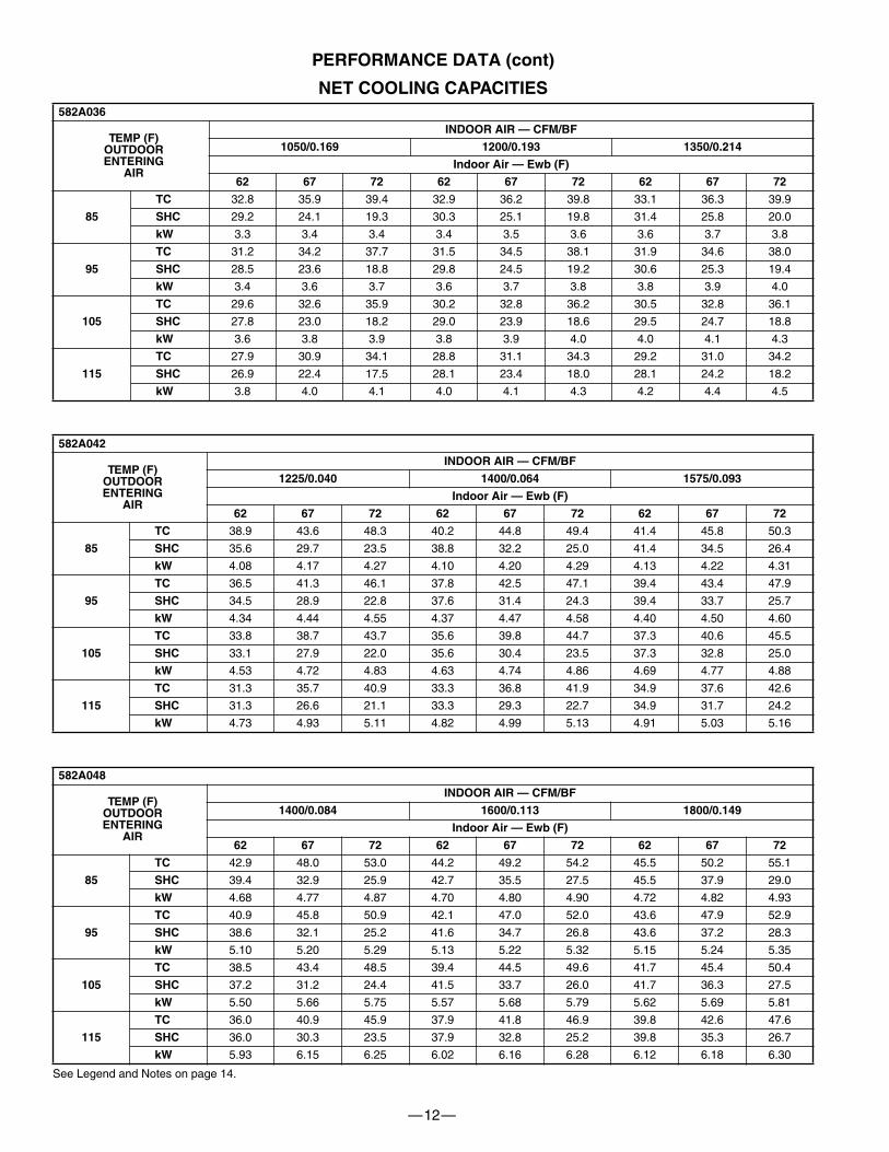
PERFORMANCE DATA (cont)
NET COOLING CAPACITIES
See Legend and Notes on page 14.
582A036
TEMP (F)OUTDOORENTERING
AIR
INDOOR AIR — CFM/BF
1050/0.169 1200/0.193 1350/0.214
Indoor Air — Ewb (F)
62 67 72 62 67 72 62 67 72
85
TC
32.8 35.9 39.4 32.9 36.2 39.8 33.1 36.3 39.9
SHC
29.2 24.1 19.3 30.3 25.1 19.8 31.4 25.8 20.0
kW
3.3 3.4 3.4 3.4 3.5 3.6 3.6 3.7 3.8
95
TC
31.2 34.2 37.7 31.5 34.5 38.1 31.9 34.6 38.0
SHC
28.5 23.6 18.8 29.8 24.5 19.2 30.6 25.3 19.4
kW
3.4 3.6 3.7 3.6 3.7 3.8 3.8 3.9 4.0
105
TC
29.6 32.6 35.9 30.2 32.8 36.2 30.5 32.8 36.1
SHC
27.8 23.0 18.2 29.0 23.9 18.6 29.5 24.7 18.8
kW
3.6 3.8 3.9 3.8 3.9 4.0 4.0 4.1 4.3
115
TC
27.9 30.9 34.1 28.8 31.1 34.3 29.2 31.0 34.2
SHC
26.9 22.4 17.5 28.1 23.4 18.0 28.1 24.2 18.2
kW
3.8 4.0 4.1 4.0 4.1 4.3 4.2 4.4 4.5
582A042
TEMP (F)OUTDOORENTERING
AIR
INDOOR AIR — CFM/BF
1225/0.040 1400/0.064 1575/0.093
Indoor Air — Ewb (F)
62 67 72 62 67 72 62 67 72
85
TC
38.9 43.6 48.3 40.2 44.8 49.4 41.4 45.8 50.3
SHC
35.6 29.7 23.5 38.8 32.2 25.0 41.4 34.5 26.4
kW
4.08 4.17 4.27 4.10 4.20 4.29 4.13 4.22 4.31
95
TC
36.5 41.3 46.1 37.8 42.5 47.1 39.4 43.4 47.9
SHC
34.5 28.9 22.8 37.6 31.4 24.3 39.4 33.7 25.7
kW
4.34 4.44 4.55 4.37 4.47 4.58 4.40 4.50 4.60
105
TC
33.8 38.7 43.7 35.6 39.8 44.7 37.3 40.6 45.5
SHC
33.1 27.9 22.0 35.6 30.4 23.5 37.3 32.8 25.0
kW
4.53 4.72 4.83 4.63 4.74 4.86 4.69 4.77 4.88
115
TC
31.3 35.7 40.9 33.3 36.8 41.9 34.9 37.6 42.6
SHC
31.3 26.6 21.1 33.3 29.3 22.7 34.9 31.7 24.2
kW
4.73 4.93 5.11 4.82 4.99 5.13 4.91 5.03 5.16
582A048
TEMP (F)OUTDOORENTERING
AIR
INDOOR AIR — CFM/BF
1400/0.084 1600/0.113 1800/0.149
Indoor Air — Ewb (F)
62 67 72 62 67 72 62 67 72
85
TC
42.9 48.0 53.0 44.2 49.2 54.2 45.5 50.2 55.1
SHC
39.4 32.9 25.9 42.7 35.5 27.5 45.5 37.9 29.0
kW
4.68 4.77 4.87 4.70 4.80 4.90 4.72 4.82 4.93
95
TC
40.9 45.8 50.9 42.1 47.0 52.0 43.6 47.9 52.9
SHC
38.6 32.1 25.2 41.6 34.7 26.8 43.6 37.2 28.3
kW
5.10 5.20 5.29 5.13 5.22 5.32 5.15 5.24 5.35
105
TC
38.5 43.4 48.5 39.4 44.5 49.6 41.7 45.4 50.4
SHC
37.2 31.2 24.4 41.5 33.7 26.0 41.7 36.3 27.5
kW
5.50 5.66 5.75 5.57 5.68 5.79 5.62 5.69 5.81
115
TC
36.0 40.9 45.9 37.9 41.8 46.9 39.8 42.6 47.6
SHC
36.0 30.3 23.5 37.9 32.8 25.2 39.8 35.3 26.7
kW
5.93 6.15 6.25 6.02 6.16 6.28 6.12 6.18 6.30
—13—
PERFORMANCE DATA (cont)
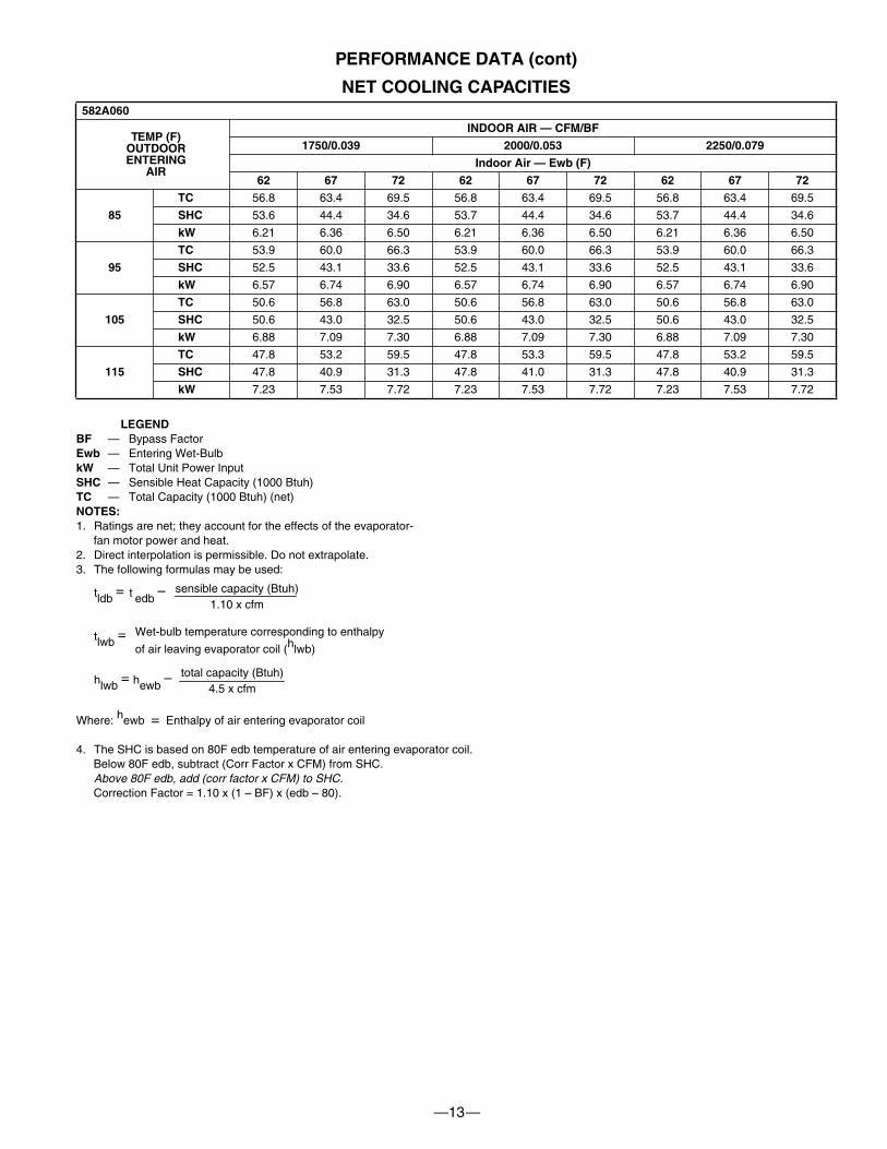
NET COOLING CAPACITIES
582A060
TEMP (F)OUTDOORENTERING
AIR
INDOOR AIR — CFM/BF
1750/0.039 2000/0.053 2250/0.079
Indoor Air — Ewb (F)
62 67 72 62 67 72 62 67 72
85
TC
56.8 63.4 69.5 56.8 63.4 69.5 56.8 63.4 69.5
SHC
53.6 44.4 34.6 53.7 44.4 34.6 53.7 44.4 34.6
kW
6.21 6.36 6.50 6.21 6.36 6.50 6.21 6.36 6.50
95
TC
53.9 60.0 66.3 53.9 60.0 66.3 53.9 60.0 66.3
SHC
52.5 43.1 33.6 52.5 43.1 33.6 52.5 43.1 33.6
kW
6.57 6.74 6.90 6.57 6.74 6.90 6.57 6.74 6.90
105
TC
50.6 56.8 63.0 50.6 56.8 63.0 50.6 56.8 63.0
SHC
50.6 43.0 32.5 50.6 43.0 32.5 50.6 43.0 32.5
kW
6.88 7.09 7.30 6.88 7.09 7.30 6.88 7.09 7.30
115
TC
47.8 53.2 59.5 47.8 53.3 59.5 47.8 53.2 59.5
SHC
47.8 40.9 31.3 47.8 41.0 31.3 47.8 40.9 31.3
kW
7.23 7.53 7.72 7.23 7.53 7.72 7.23 7.53 7.72
LEGENDBF — Bypass FactorEwb — Entering Wet-BulbkW — Total Unit Power InputSHC — Sensible Heat Capacity (1000 Btuh)TC — Total Capacity (1000 Btuh) (net)NOTES:1. Ratings are net; they account for the effects of the evaporator-
fan motor power and heat.2. Direct interpolation is permissible. Do not extrapolate.3. The following formulas may be used:
tldb = .t edb
–
tlwb =
hlwb = hewb
–
Where: hewb = Enthalpy of air entering evaporator coil
4. The SHC is based on 80F edb temperature of air entering evaporator coil. Below 80F edb, subtract (Corr Factor x CFM) from SHC.Above 80F edb, add (corr factor x CFM) to SHC. Correction Factor = 1.10 x (1 – BF) x (edb – 80).
sensible capacity (Btuh)1.10 x cfm
Wet-bulb temperature corresponding to enthalpy
of air leaving evaporator coil (hlwb)
total capacity (Btuh)4.5 x cfm
—14—
PERFORMANCE DATA (cont)
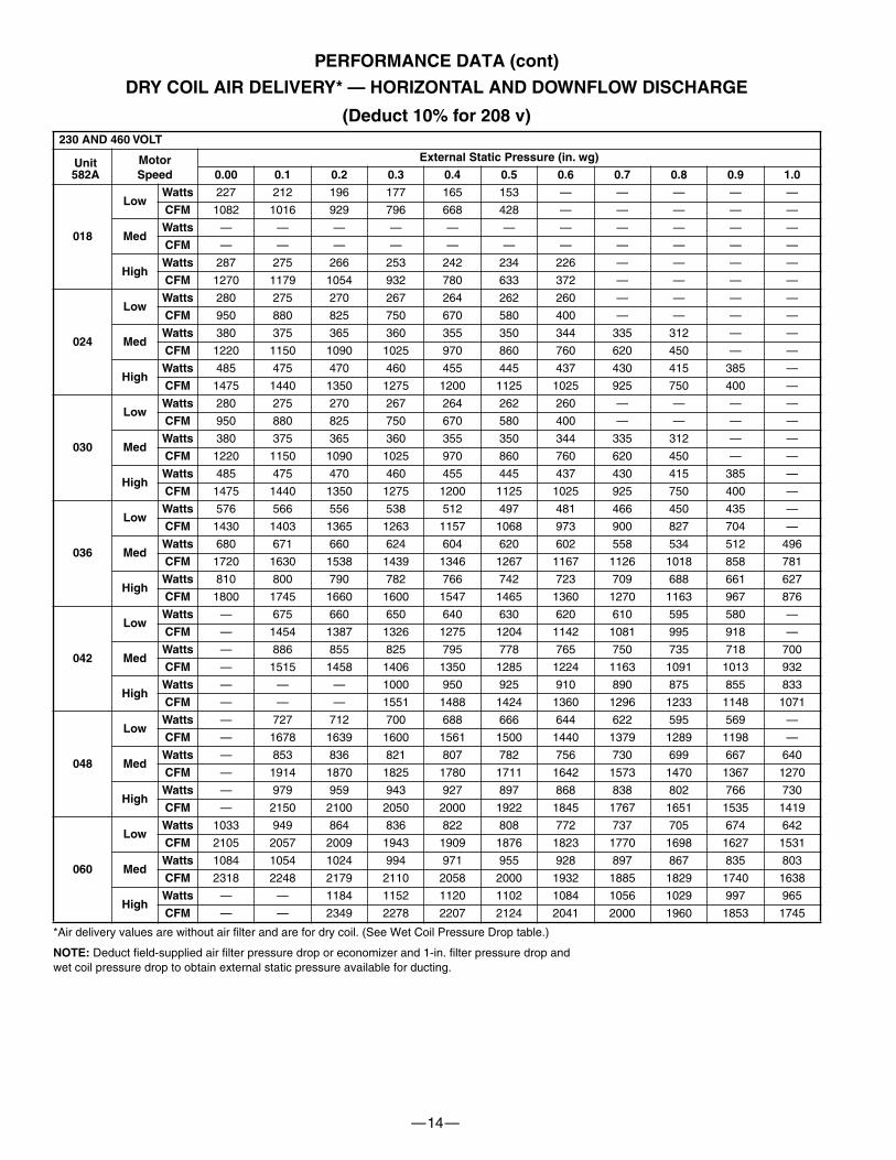
DRY COIL AIR DELIVERY* — HORIZONTAL AND DOWNFLOW DISCHARGE
(Deduct 10% for 208 v)
*Air delivery values are without air filter and are for dry coil. (See Wet Coil Pressure Drop table.)
NOTE: Deduct field-supplied air filter pressure drop or economizer and 1-in. filter pressure drop andwet coil pressure drop to obtain external static pressure available for ducting.
230 AND 460 VOLT
Unit582A
MotorSpeed
External Static Pressure (in. wg)
0.00 0.1 0.2 0.3 0.4 0.5 0.6 0.7 0.8 0.9 1.0
018
LowWatts 227 212 196 177 165 153 — — — — —
CFM 1082 1016 929 796 668 428 — — — — —
MedWatts — — — — — — — — — — —
CFM — — — — — — — — — — —
HighWatts 287 275 266 253 242 234 226 — — — —
CFM 1270 1179 1054 932 780 633 372 — — — —
024
LowWatts 280 275 270 267 264 262 260 — — — —
CFM 950 880 825 750 670 580 400 — — — —
MedWatts 380 375 365 360 355 350 344 335 312 — —
CFM 1220 1150 1090 1025 970 860 760 620 450 — —
HighWatts 485 475 470 460 455 445 437 430 415 385 —
CFM 1475 1440 1350 1275 1200 1125 1025 925 750 400 —
030
LowWatts 280 275 270 267 264 262 260 — — — —
CFM 950 880 825 750 670 580 400 — — — —
MedWatts 380 375 365 360 355 350 344 335 312 — —
CFM 1220 1150 1090 1025 970 860 760 620 450 — —
HighWatts 485 475 470 460 455 445 437 430 415 385 —
CFM 1475 1440 1350 1275 1200 1125 1025 925 750 400 —
036
LowWatts 576 566 556 538 512 497 481 466 450 435 —
CFM 1430 1403 1365 1263 1157 1068 973 900 827 704 —
MedWatts 680 671 660 624 604 620 602 558 534 512 496
CFM 1720 1630 1538 1439 1346 1267 1167 1126 1018 858 781
HighWatts 810 800 790 782 766 742 723 709 688 661 627
CFM 1800 1745 1660 1600 1547 1465 1360 1270 1163 967 876
042
LowWatts — 675 660 650 640 630 620 610 595 580 —
CFM — 1454 1387 1326 1275 1204 1142 1081 995 918 —
MedWatts — 886 855 825 795 778 765 750 735 718 700
CFM — 1515 1458 1406 1350 1285 1224 1163 1091 1013 932
HighWatts — — — 1000 950 925 910 890 875 855 833
CFM — — — 1551 1488 1424 1360 1296 1233 1148 1071
048
LowWatts — 727 712 700 688 666 644 622 595 569 —
CFM — 1678 1639 1600 1561 1500 1440 1379 1289 1198 —
MedWatts — 853 836 821 807 782 756 730 699 667 640
CFM — 1914 1870 1825 1780 1711 1642 1573 1470 1367 1270
HighWatts — 979 959 943 927 897 868 838 802 766 730
CFM — 2150 2100 2050 2000 1922 1845 1767 1651 1535 1419
060
LowWatts 1033 949 864 836 822 808 772 737 705 674 642
CFM 2105 2057 2009 1943 1909 1876 1823 1770 1698 1627 1531
MedWatts 1084 1054 1024 994 971 955 928 897 867 835 803
CFM 2318 2248 2179 2110 2058 2000 1932 1885 1829 1740 1638
HighWatts — — 1184 1152 1120 1102 1084 1056 1029 997 965
CFM — — 2349 2278 2207 2124 2041 2000 1960 1853 1745
—15—
PERFORMANCE DATA (cont)
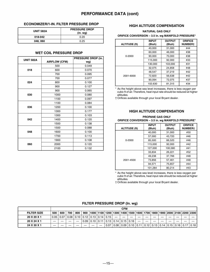
ECONOMIZER/1-IN. FILTER PRESSURE DROP
WET COIL PRESSURE DROP
FILTER PRESSURE DROP (In. wg)
UNIT 582APRESSURE DROP
(in. wg)
018-042 0.20
048, 060 0.25
UNIT 582AAIRFLOW (CFM)
PRESSURE DROP (in. wg)
018
500 0.049
600 0.070
700 0.095
024
700 0.077
800 0.100
900 0.127
030
900 0.065
1000 0.080
1100 0.097
036
1100 0.084
1200 0.100
1300 0.177
042
1300 0.103
1400 0.120
1500 0.138
048
1500 0.088
1600 0.100
1700 0.113
060
1900 0.108
2000 0.120
2100 0.132
CFM
FILTER SIZE 500 600 700 800 900 1000 1100 1200 1300 1400 1500 1600 1700 1800 1900 2000 2100 2200 2300
20 X 20 X 1 0.05 0.07 0.08 0.10 0.12 0.13 0.14 0.15 — — — — — — — — — — —
20 X 24 X 1 — — — — 0.09 0.10 0.11 0.13 0.14 0.15 0.16 — — — — — — — —
24 X 30 X 1 — — — — — — — 0.07 0.08 0.09 0.10 0.11 0.12 0.13 0.14 0.15 0.16 0.17 0.18
HIGH ALTITUDE COMPENSATION
NATURAL GAS ONLY
ORIFICE CONVERSION – 3.5 in. wg MANIFOLD PRESSURE*
* As the height above sea level increases, there is less oxygen per cubic ft of air. Therefore, heat input rate should be reduced at higher altitudes.
† Orifices available through your local Bryant dealer.
HIGH ALTITUDE COMPENSATION
PROPANE GAS ONLYORIFICE CONVERSION – 3.5 in. wg MANIFOLD PRESSURE*
* As the height above sea level increases, there is less oxygen per cubic ft of air. Therefore, heat input rate should be reduced at higher altitudes.
† Orifices available through your local Bryant dealer.
ALTITUDE (ft)INPUT(Btuh)
OUTPUT(Btuh)
ORIFICENUMBER†
0-2000
40,000 31,000 #44
60,000 46,000 #38
90,000 70,000 #38
115,000 92,000 #33
130,000 103,000 #31
2001-6000
32,075 24,858 #48
48,547 37,219 #42
72,820 56,638 #42
90,094 72,075 #37
102,630 81,315 #34
ALTITUDE (ft)INPUT(Btuh)
OUTPUT(Btuh)
ORIFICENUMBER†
0-2000
40,000 31,000 #50
57,000 43,720 #46
85,500 66,520 #46
115,000 92,000 #42
127,000 100,580 #41
2001-4500
33,834 26,221 #52
49,238 37,766 #48
73,856 57,461 #48
94,571 75,657 #44
101,284 80,214 #43
—16—
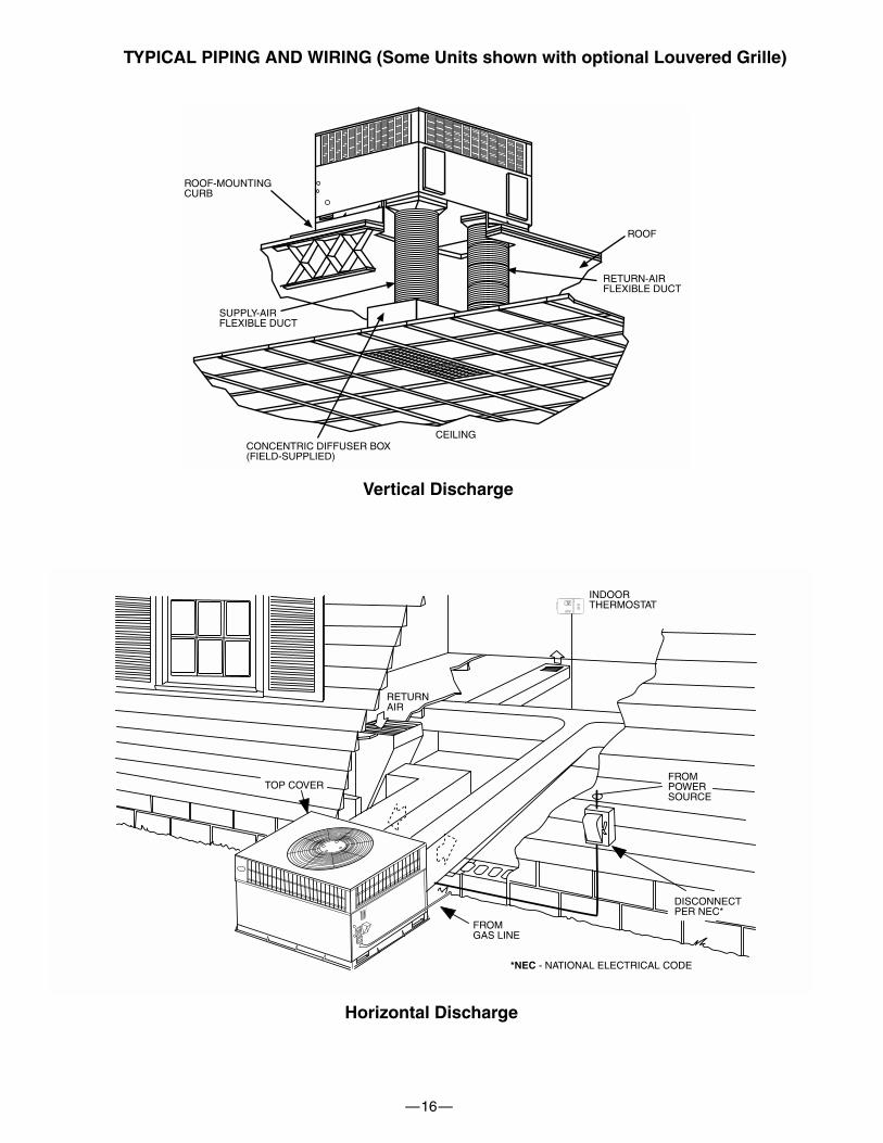
TYPICAL PIPING AND WIRING (Some Units shown with optional Louvered Grille)
INDOORTHERMOSTAT
DISCONNECTPER NEC*
FROMPOWERSOURCE
RETURNAIR
TOP COVER
FROMGAS LINE
*NEC - NATIONAL ELECTRICAL CODE
ROOF
RETURN-AIRFLEXIBLE DUCT
CEILINGCONCENTRIC DIFFUSER BOX(FIELD-SUPPLIED)
SUPPLY-AIRFLEXIBLE DUCT
ROOF-MOUNTINGCURB
Vertical Discharge
Horizontal Discharge
—17—
APPLICATION DATA
CONDENSATE TRAP — A 2-in. condensate trap must be fieldsupplied.
DUCTWORK — Secure downflow discharge ductwork to roofcurb. For horizontal discharge applications, attach ductwork tounit with flanges.
TO CONVERT A UNIT TO DOWNFLOW DISCHARGE — Unitsare equipped with factory-installed inserts in the downflowopenings. Removal of the inserts is similar to removing anelectrical knock-out. Use the duct cover supplied to seal thehorizontal discharge openings in the unit. Units installedhorizontal discharge orientation do not require duct covers.
MAXIMUM COOLING AIRFLOW — To minimize the possibilityof condensate blow-off from the evaporator, airflow through theunits should not exceed 450 cfm per ton.
MINIMUM COOLING AIRFLOW — Minimum cooling airflow is350 cfm per ton.
MINIMUM COOLING AMBIENT OPERATING TEMPERA-TURE — For all standard units the minimum ambient operatingtemperature is 40°F. With accessory low ambient temperaturekit, units can operate at temperatures down to 0°F.
MINIMUM TEMPERATURE — Air entering the heat exchangerin heating mode must be a minimum of 50°F continuous and/or45°F intermittent.
—18—
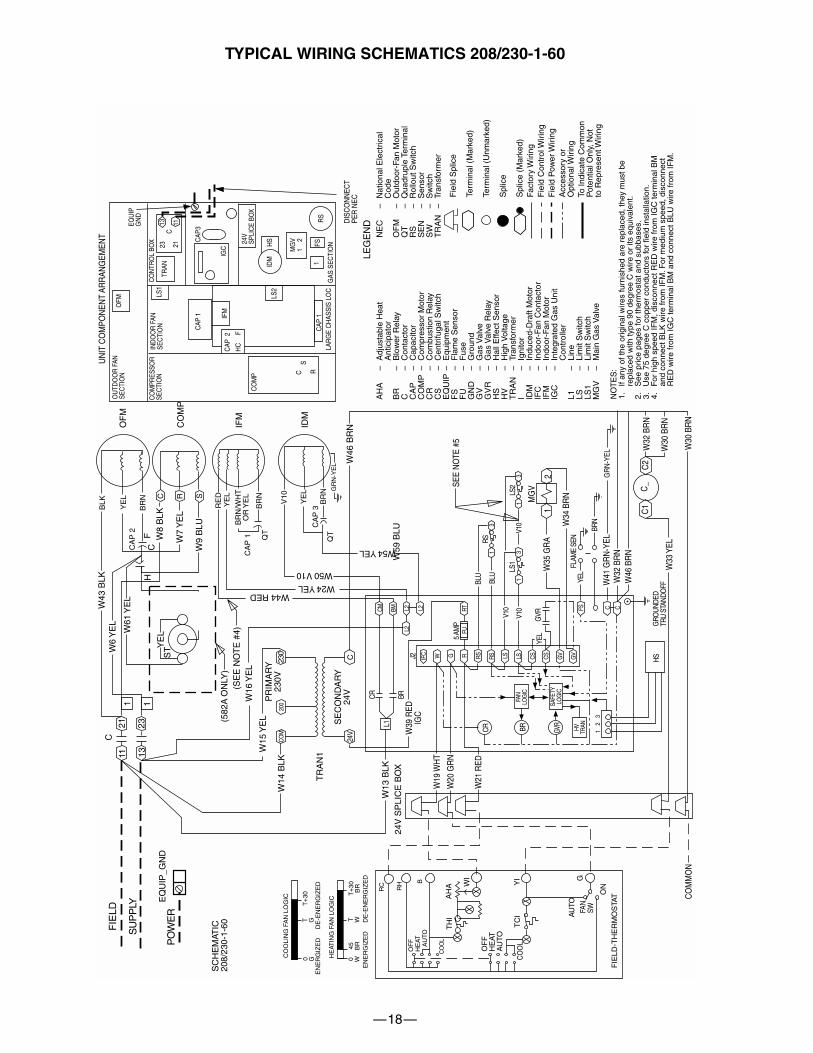
TYPICAL WIRING SCHEMATICS 208/230-1-60
NO
TE
S:
1.If
any
of th
e or
igin
al w
ires
furn
ishe
d ar
e re
plac
ed, t
hey
mus
t be
repl
aced
with
type
90
degr
ee C
wire
or
its e
quiv
alen
t.2.
See
pric
e pa
ges
for
ther
mos
tat a
nd s
ubba
ses.
3.U
se 7
5 de
gree
C c
oppe
r co
nduc
tors
for
field
inst
alla
tion.
4.F
or h
igh
spee
d IF
M, d
isco
nnec
t RE
D w
ire fr
om IG
C te
rmin
al B
Man
d co
nnec
t BLK
wire
from
IFM
. For
med
ium
spe
ed, d
isco
nnec
tR
ED
wire
from
IGC
term
inal
BM
and
con
nect
BLU
wire
from
IFM
.5.
Mod
els
4BG
X02
4-03
6 ha
ve L
S1
and
LS2
wire
d in
ser
ies.
Mod
els
48G
X04
2-06
0 ha
ve L
S1
only
.
UN
IT C
OM
PON
ENT
ARR
ANG
EMEN
T
DIS
CO
NN
ECT
PER
NEC
GAS
SEC
TIO
N
OU
TDO
OR
FAN
SEC
TIO
N
CO
MPR
ESSO
RSE
CTI
ON
IND
OO
R F
ANSE
CTI
ON
CO
NTR
OL
BOX 24
VSP
LIC
E BO
X
EQU
IPG
ND
OFM
TRAN
CAP
1
LS1
IFM
CAP
3
IGC
CAP
2
HC
F
23 21C
13 11
CO
MP C
SR
IDM
HS
MG
V1
2
1R
SFS
CO
OLI
NG
FA
N L
OG
IC
EN
ER
GIZ
ED
D
E-E
NE
RG
IZE
D
EN
ER
GIZ
ED
D
E-E
NE
RG
IZE
D
HE
ATIN
G F
AN
LO
GIC
FIE
LD
SU
PP
LY
EQ
UIP
_GN
D
W15
YE
L
W14
BLK
PR
IMA
RY
230V
1121
1323
C
W16
YE
L
W43
BLK
C
BLK
YE
L
BR
NC
AP
2
C R S
W8
BLK
W7
YE
L
RE
DY
EL
BR
N/W
HT
OR
YE
L
BR
N
V10
YE
L
BR
N
CA
P 1
CA
P 3
OF
M
CO
MP
IFM
IDM
(SE
E N
OT
E #
4)
GR
N-Y
EL
W24 YEL
W50 V10
QT
QT
W46
BR
NS
EC
ON
DA
RY
24V
TR
AN
1
1 1
230
C24
V
COM
0 GT G
0 WT W
T+
30 T+
30B
R45 BR
RC
RH B
OF
FH
EAT
A
UTO
CO
OL
TH
IA
HA W
I
OF
FH
EAT
AU
TO
YI
TC
IC
OO
L
AU
TO
FAN
SW
FIE
LD-T
HE
RM
OS
TATO
N
G
W13
BLK
24V
SP
LIC
E B
OX
W19
WH
T
W20
GR
N
W21
RED
L1CM BM L2
L2
L2J2 IF
C W G R
CR BRW
39 R
EDIG
C
RS RS LS LS CS CS GV
GV
CR BR GVR
FAN
LOG
IC
SAFE
TYLO
GIC
5 AM
PFU
RT
BLU
BLU
V10
V10
GVR
W35
GR
A
MG
V
W34
BR
NFL
AME
SEN
YEL
BRN
W41
GR
N-Y
ELW
32 B
RN
W46
BR
N
GR
N-Y
EL
W32
BR
N
W30
BR
NW
33 Y
EL
GRO
UNDE
DTR
U ST
ANDO
FFHS
HV TRAN
FS C C
YEL
RS
LS1
13
C1
C2
C_
W30
BR
NC
OM
MO
N
200
W44 RED
12
1 2
3
LS2
13
V10
SEE
NO
TE #
5
PO
WE
R
SC
HE
MAT
IC20
8/23
0-1-
60
W54 YEL
LS2
CAP
1LA
RG
E C
HAS
SIS
LOC
AH
A–
Adj
usta
ble
Hea
tA
ntic
ipat
orB
R–
Blo
wer
Rel
ayC
–C
onta
ctor
CA
P–
Cap
acito
rC
OM
P–
Com
pres
sor
Mot
orC
R–
Com
bust
ion
Rel
ayC
S–
Cen
trifu
gal S
witc
hE
QU
IP–
Equ
ipm
ent
FS
–F
lam
e S
enso
rF
U–
Fus
eG
ND
–G
roun
dG
V–
Gas
Val
veG
VR
–G
as V
alve
Rel
ayH
S–
Hal
l Effe
ct S
enso
rH
V–
Hig
h V
olta
geT
RA
N–
Tran
sfor
mer
I–
Igni
tor
IDM
–In
duce
d-D
raft
Mot
orIF
C–
Indo
or-F
an C
onta
ctor
IFM
–In
door
-Fan
Mot
orIG
C–
Inte
grat
ed G
as U
nit
Con
trol
ler
L1–
Line
LS–
Lim
it S
witc
hLS
1–
Lim
it S
witc
hM
GV
–M
ain
Gas
Val
ve
NE
C–
Nat
iona
l Ele
ctric
alC
ode
OF
M–
Out
door
-Fan
Mot
orQ
T–
Qua
drup
le T
erm
inal
RS
–R
ollo
ut S
witc
hS
EN
–S
enso
rS
W–
Sw
itch
TR
AN
–Tr
ansf
orm
er
LEG
EN
D
13
W6
YE
L
HF
W9
BLU
YE
LW61
YE
L
ST
W59
BLU
(582
A O
NLY
)
Fie
ld S
plic
e
Term
inal
(M
arke
d)
Term
inal
(U
nmar
ked)
Spl
ice
Spl
ice
(Mar
ked)
Fact
ory
Wiri
ngF
ield
Con
trol
Wiri
ngF
ield
Pow
er W
iring
Acc
esso
ry o
rO
ptio
nal W
iring
To In
dica
te C
omm
onP
oten
tial O
nly,
Not
to R
epre
sent
Wiri
ng
—19—
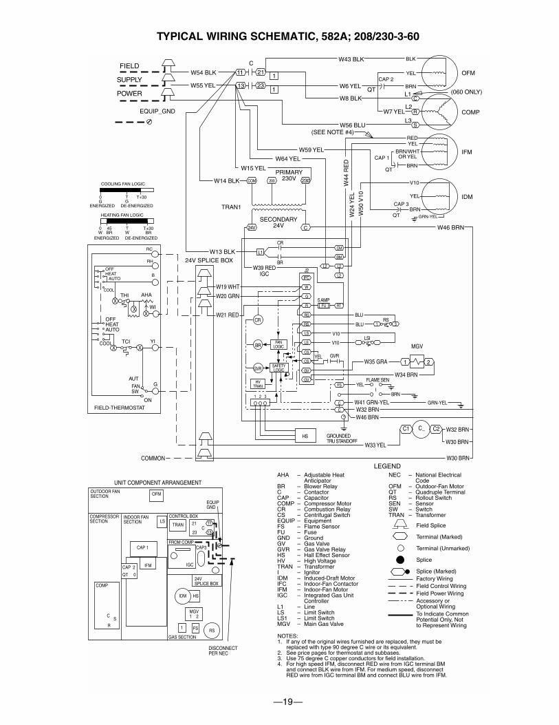
TYPICAL WIRING SCHEMATIC, 582A; 208/230-3-60
COOLING FAN LOGIC
ENERGIZED DE-ENERGIZED
ENERGIZED DE-ENERGIZED
HEATING FAN LOGIC
FIELD
SUPPLY
POWER
W54 BLK
W55 YEL
EQUIP_GND
W15 YEL
W14 BLKPRIMARY
230V
11 21
13 23
C
W59 YEL
W64 YEL
W43 BLK
W6 YEL
W8 BLKQT
BLK
YEL
BRNCAP 2
C
R
S
L1
L2
L3
W7 YEL
W56 BLU
REDYEL
BRN/WHTOR YEL
BRN
V10
YEL
BRN
CAP 1
CAP 3
OFM
COMP
IFM
IDM
(SEE NOTE #4)
GRN-YELW24
YE
L
W50
V10
QT
QT
W46 BRNSECONDARY
24V
TRAN1
1
1
230
C24V
COM
0G
TG
0W
TW
T+30
T+30BR
45BR
RC
RH
BOFFHEAT AUTO
COOLTHI AHA
WI
OFFHEATAUTO
YITCICOOL
AUTO
FANSW
FIELD-THERMOSTAT
ON
G
W13 BLK24V SPLICE BOX
W19 WHT
W20 GRN
W21 RED
L1CM
BM
L2L2
L2J2IFC
W
G
R
CR
BRW39 RED
IGC
RS
RS
LS
LS
CS
CS
GV
GV
CR
BR
GVR
FANLOGIC
SAFETYLOGIC
5 AMPFU RT
BLU
BLU
V10
V10
GVRW35 GRA
MGV
W34 BRNFLAME SEN
YEL
BRN
W41 GRN-YELW32 BRNW46 BRN
GRN-YEL
W32 BRN
W30 BRNW33 YEL
GROUNDEDTRU STANDOFF
HS
HVTRAN FS
C
C
YEL
RS
LSI
1 3
C1 C2C_
W30 BRNCOMMON
UNIT COMPONENT ARRANGEMENT
DISCONNECTPER NEC
GAS SECTION
OUTDOOR FANSECTION
COMPRESSORSECTION
INDOOR FANSECTION
CONTROL BOX
FROM COMP
24VSPLICE BOX
EQUIPGND
OFM
TRAN
CAP 1
LS
IFM
CAP3
IGCCAP 2
QT 0
21
23C
11
13
COMP
CS
R
IDM HS
MGV1 2
1RSFS
200
W44
RE
D
(060 ONLY)
1 2
1 2 3
NOTES:1. If any of the original wires furnished are replaced, they must be
replaced with type 90 degree C wire or its equivalent.2. See price pages for thermostat and subbases.3. Use 75 degree C copper conductors for field installation.4. For high speed IFM, disconnect RED wire from IGC terminal BM
and connect BLK wire from IFM. For medium speed, disconnectRED wire from IGC terminal BM and connect BLU wire from IFM.
5. Models 4BGX024-036 have LS1 and LS2 wired in series. Models48GX042-060 have LS1 only.
AHA – Adjustable HeatAnticipator
BR – Blower RelayC – ContactorCAP – CapacitorCOMP – Compressor MotorCR – Combustion RelayCS – Centrifugal SwitchEQUIP – EquipmentFS – Flame SensorFU – FuseGND – GroundGV – Gas ValveGVR – Gas Valve RelayHS – Hall Effect SensorHV – High VoltageTRAN – TransformerI – IgnitorIDM – Induced-Draft MotorIFC – Indoor-Fan ContactorIFM – Indoor-Fan MotorIGC – Integrated Gas Unit
ControllerL1 – LineLS – Limit SwitchLS1 – Limit SwitchMGV – Main Gas Valve
NEC – National ElectricalCode
OFM – Outdoor-Fan MotorQT – Quadruple TerminalRS – Rollout SwitchSEN – SensorSW – SwitchTRAN – Transformer
LEGEND
Field Splice
Terminal (Marked)
Terminal (Unmarked)
Splice
Splice (Marked)Factory WiringField Control WiringField Power WiringAccessory orOptional WiringTo Indicate CommonPotential Only, Notto Represent Wiring
—20—
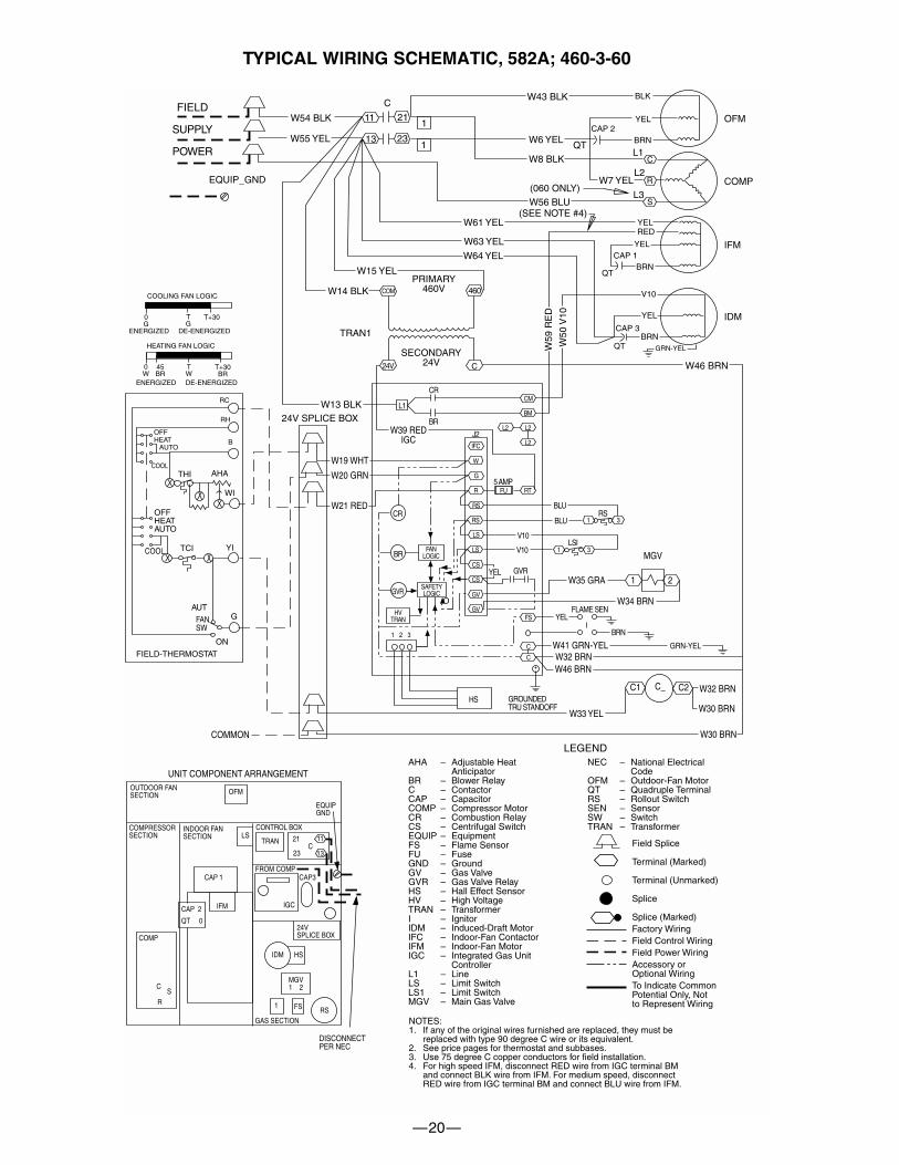
TYPICAL WIRING SCHEMATIC, 582A; 460-3-60
COOLING FAN LOGIC
ENERGIZED DE-ENERGIZED
ENERGIZED DE-ENERGIZED
HEATING FAN LOGIC
FIELD
SUPPLY
POWER
W54 BLK
W55 YEL
EQUIP_GND
W15 YEL
W14 BLKPRIMARY
460V
11 21
13 23
C
W61 YEL
W63 YEL
W64 YEL
W43 BLK
W6 YEL
W8 BLKQT
BLK
YEL
BRNCAP 2
C
R
S
L1
L2
L3
W7 YEL
W56 BLU
YELRED
YEL
BRN
V10
YEL
BRN
CAP 1
CAP 3
OFM
COMP
IFM
IDM
(060 ONLY)
(SEE NOTE #4)
GRN-YELW59
RE
D
W50
V10
QT
QT
W46 BRNSECONDARY
24V
TRAN1
1
1
460
C24V
COM
0G
TG
0W
TW
T+30
T+30BR
45BR
RC
RH
BOFFHEAT AUTO
COOLTHI AHA
WI
OFFHEATAUTO
YITCICOOL
AUTO
FANSW
FIELD-THERMOSTAT
ON
G
W13 BLK24V SPLICE BOX
W19 WHT
W20 GRN
W21 RED
L1CM
BM
L2L2
L2J2IFC
W
G
R
CR
BRW39 RED
IGC
RS
RS
LS
LS
CS
CS
GV
GV
CR
BR
GVR
FANLOGIC
SAFETYLOGIC
5 AMPFU RT
BLU
BLU
V10
V10
GVRW35 GRA
MGV
W34 BRNFLAME SEN
YEL
BRN
W41 GRN-YELW32 BRNW46 BRN
GRN-YEL
W32 BRN
W30 BRNW33 YEL
GROUNDEDTRU STANDOFF
HS
HVTRAN FS
C
C
YEL
RS
LSI
1 3
1 3
C1 C2C_
W30 BRNCOMMON
UNIT COMPONENT ARRANGEMENT
DISCONNECTPER NEC
GAS SECTION
OUTDOOR FANSECTION
COMPRESSORSECTION
INDOOR FANSECTION
CONTROL BOX
FROM COMP
24VSPLICE BOX
EQUIPGND
OFM
TRAN
CAP 1
LS
IFM
CAP3
IGCCAP 2
QT 0
21
23C
11
13
COMP
CS
R
IDM HS
MGV1 2
1RSFS
1 2
1 2 3
NOTES:1. If any of the original wires furnished are replaced, they must be
replaced with type 90 degree C wire or its equivalent.2. See price pages for thermostat and subbases.3. Use 75 degree C copper conductors for field installation.4. For high speed IFM, disconnect RED wire from IGC terminal BM
and connect BLK wire from IFM. For medium speed, disconnectRED wire from IGC terminal BM and connect BLU wire from IFM.
5. Models 4BGX024-036 have LS1 and LS2 wired in series. Models48GX042-060 have LS1 only.
AHA – Adjustable HeatAnticipator
BR – Blower RelayC – ContactorCAP – CapacitorCOMP – Compressor MotorCR – Combustion RelayCS – Centrifugal SwitchEQUIP – EquipmentFS – Flame SensorFU – FuseGND – GroundGV – Gas ValveGVR – Gas Valve RelayHS – Hall Effect SensorHV – High VoltageTRAN – TransformerI – IgnitorIDM – Induced-Draft MotorIFC – Indoor-Fan ContactorIFM – Indoor-Fan MotorIGC – Integrated Gas Unit
ControllerL1 – LineLS – Limit SwitchLS1 – Limit SwitchMGV – Main Gas Valve
NEC – National ElectricalCode
OFM – Outdoor-Fan MotorQT – Quadruple TerminalRS – Rollout SwitchSEN – SensorSW – SwitchTRAN – Transformer
LEGEND
Field Splice
Terminal (Marked)
Terminal (Unmarked)
Splice
Splice (Marked)Factory WiringField Control WiringField Power WiringAccessory orOptional WiringTo Indicate CommonPotential Only, Notto Represent Wiring
—21—
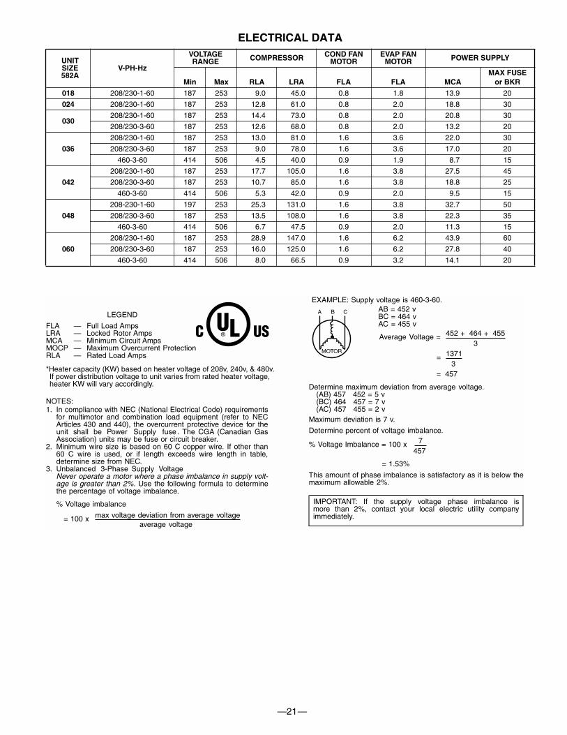
ELECTRICAL DATA
UNITSIZE582A
V-PH-Hz
VOLTAGERANGE COMPRESSOR COND FAN
MOTOREVAP FAN
MOTOR POWER SUPPLY
Min Max RLA LRA FLA FLA MCAMAX FUSE
or BKR
018 208/230-1-60 187 253 9.0 45.0 0.8 1.8 13.9 20
024 208/230-1-60 187 253 12.8 61.0 0.8 2.0 18.8 30
030208/230-1-60 187 253 14.4 73.0 0.8 2.0 20.8 30
208/230-3-60 187 253 12.6 68.0 0.8 2.0 13.2 20
036
208/230-1-60 187 253 13.0 81.0 1.6 3.6 22.0 30
208/230-3-60 187 253 9.0 78.0 1.6 3.6 17.0 20
460-3-60 414 506 4.5 40.0 0.9 1.9 8.7 15
042
208/230-1-60 187 253 17.7 105.0 1.6 3.8 27.5 45
208/230-3-60 187 253 10.7 85.0 1.6 3.8 18.8 25
460-3-60 414 506 5.3 42.0 0.9 2.0 9.5 15
048
208-230-1-60 197 253 25.3 131.0 1.6 3.8 32.7 50
208/230-3-60 187 253 13.5 108.0 1.6 3.8 22.3 35
460-3-60 414 506 6.7 47.5 0.9 2.0 11.3 15
060
208/230-1-60 187 253 28.9 147.0 1.6 6.2 43.9 60
208/230-3-60 187 253 16.0 125.0 1.6 6.2 27.8 40
460-3-60 414 506 8.0 66.5 0.9 3.2 14.1 20
452 = 5 v457 = 7 v455 = 2 v
LEGEND
FLA — Full Load AmpsLRA — Locked Rotor AmpsMCA — Minimum Circuit AmpsMOCP — Maximum Overcurrent ProtectionRLA — Rated Load Amps
NOTES:1. In compliance with NEC (National Electrical Code) requirements
for multimotor and combination load equipment (refer to NECArticles 430 and 440), the overcurrent protective device for theunit shall be Power Supply fuse . The CGA (Canadian GasAssociation) units may be fuse or circuit breaker.
2. Minimum wire size is based on 60 C copper wire. If other than60 C wire is used, or if length exceeds wire length in table,determine size from NEC.
3. Unbalanced 3-Phase Supply VoltageNever operate a motor where a phase imbalance in supply volt-age is greater than 2%. Use the following formula to determinethe percentage of voltage imbalance.
% Voltage imbalance
max voltage deviation from average voltage= 100 xaverage voltage
EXAMPLE: Supply voltage is 460-3-60.AB = 452 vBC = 464 vAC = 455 v
452 + 464 + 455Average Voltage =3
1371=3
= 457
Determine maximum deviation from average voltage.(AB) 457(BC) 464(AC) 457
Maximum deviation is 7 v.
Determine percent of voltage imbalance.7% Voltage Imbalance = 100 x
457
= 1.53%
This amount of phase imbalance is satisfactory as it is below themaximum allowable 2%.
IMPORTANT: If the supply voltage phase imbalance ismore than 2%, contact your local electric utility companyimmediately.
®
*Heater capacity (KW) based on heater voltage of 208v, 240v, & 480v.If power distribution voltage to unit varies from rated heater voltage,heater KW will vary accordingly.
—22—
OPERATING SEQUENCE
Heating — When the thermostat calls for heating, terminal “W”is energized, starting the induced draft motor. When the hall-effect sensor on the induced-draft motor senses that it hasreached the required speed, the burner ignition sequence be-gins. The indoor (evaporator) fan motor (IFM) is energized 45seconds after flame is established. When the thermostat is sat-isfied and “W” is deenergized, the IFM stops after a 45-secondtime-off delay.Cooling — When the system thermostat calls for cooling, 24 Vis supplied to the “Y” and “G” terminals of the thermostat. Thiscompletes the circuit to the contactor coil (C) and indoor (evap-orator) blower relay (BR). The normally open contacts of ener-gized C close and complete the circuit through compressor
motor (COMP) to outdoor (condenser) fan motor (OFM). Bothmotors start instantly. The set of normally open contacts of en-ergized BR close and complete the circuit through IFM. The IFMstarts instantly.
On the loss of the thermostat call for cooling, 24 V is removedfrom both the “Y” and “G” terminals (provided the fan switch isin the “AUTO” position) deenergizing the compressor contactorand opening the contacts supplying power to compressor/OFM. After a 30-second delay, the IFM shuts off. If the thermo-stat fan selector switch is in the “ON” position, the IFM will runcontinuously.
NOTE: On units with a Time Guard® II device: Once the com-pressor has started and then stopped, it cannot be restartedagain until five minutes have elapsed.
CONTROLS
—23—
GUIDE SPECIFICATIONSPackaged Heating/Cooling UnitsConstant Volume ApplicationHVAC Guide SpecificationsSize Range:1-1/2 to 5 Tons, Nominal Cooling
40,000 to 130,000 Btuh,Nominal Heating Input
BRYANT MODEL NUMBER: 582APART 1 — GENERAL1.01 SYSTEM DESCRIPTION
Outdoor rooftop mounted, gas heating/electric cooling unitutilizing a hermetic compressor for cooling duty. Unit shalldischarge supply air vertically or horizontally as shown oncontract drawings. Condenser fan/coil section shall have adraw-thru design with vertical discharge for minimum soundlevels.
1.02 QUALITY ASSURANCEA. Unit shall be rated in accordance with ARI Standards
210/240-89 and 270-89.B. Unit shall be designed in accordance with UL Standard
1995.C. Unit shall be manufactured in a facility registered to ISO
9001 manufacturing quality standard.D. Unit shall be UL listed and c-UL certified as a total
package for safety requirements.E. Roof curb shall be designed to conform to NRCA
Standards.F. Insulation and adhesives shall meet NFPA 90A
requirements for flame spread and smoke generation.G. Cabinet insulation shall meet ASHRAE Standard 62P.
1.03 DELIVERY, STORAGE AND HANDLINGUnit shall be stored and handled per manufacturer’srecommendations.PART 2 — PRODUCTS2.01 EQUIPMENT
A. General:Factory-assembled, single-piece, heating and coolingunit. Contained within the enclosure shall be all factorywiring, piping, controls, refrigerant chage (R-22), andspecial features required prior to field start-up.
B. Unit Cabinet:1. Unit Cabinet shall be constructed of phosphated,
zinc-coated, pre-painted steel capable of with-standing 500 hours in salt spray.
2. Normal service shall be through a single removablecabinet panel.
3. The unit shall be constructed on a rust proof unitbase that has an externally trapped, integratedsloped drain.
4. Evaporator fan compartment top surface shall beinsulated with a minimum 1/2-in. thick, flexiblefiberglass insulation, coated on the air side andretained by adhesive and mechanical means. Theevaporator wall sections will be insulated with aminimum semi-rigid foil-faced board capable ofbeing wiped clean. Aluminum foil-faced fiberglassinsulation shall be used in the entire indoor air cavitysection.
5. Unit shall have a field-supplied condensate trap.C. Fans:
1. The evaporator fan shall be 3-speed, direct-drive, asshown on equipment drawings.
2. Fan wheel shall be made from steel, be double-inlettype with forward curved blades with corrosionresistant finish and be dynamically balanced.
3. Condenser fan shall be direct drive propeller typewith aluminum blades riveted to corrosion resistantsteel spiders, be dynamically balanced, anddischarge air vertically.
D. Compressor:1. Fully hermetic compressors with factory-installed
vibration isolation.2. Reciprocating and/or scroll compressors shall be
standard on all units.E. Coils:
Evaporator and consdensor coils shall have aluminumplate fins mechanically bonded to seamless coppertubes with all joints brazed (copper/copper and vinyl-coated construction available as factory-installedoption). Tube sheet openings shall be belled to preventtube wear.
F. Heating Section:1. Induced-draft combustion type with energy saving
direct spark ignition system and redundant main gasvalve.
2. Induced-draft motors shall be provided with solid-state hall-effect sensor to ensure adequate airflowfor combustion.
3. The heat exchangers shall be constructed ofaluminized steel for corrosion resistance.
4. Burners shall be of the in-shot type constructed ofaluminum coated steel.
5. All gas piping and electric power shall enter the unitcabinet at a single location.
G. Refrigerant Components:Refrigerant components shall be of the fixed orifice feedtype.
H. Filter section shall consist of field-installed, throwaway,1-in. thick fiberglass filters of commercially availablesizes.
I. Controls and Safeties:1. Unit controls shall be complete with a self-contained
low voltage control circuit.2. Safeties: Compressors shall incorporate a solid-state
compressor protector that provides reset capability.J. Operating Characteristics:
1. Unit shall be capable of starting and running at125°F ambient outdoor temperature per maximumload criteria of ARI Standard 210.
2. Compressor with standard controls shall be capable ofoperation down to 40°F ambient outdoor temperature.
3. Units shall be provided with fan time delay to preventcold air delivery before the heat exchanger warms up.
4. Unit shall be provided with 30-second fan time delayafter the thermostat is satisfied.
K. Electrical Requirements:All unit power wiring shall enter the unit cabinet at a sin-gle location.
L. Motors:1. Compressor motors shall be of the refrigerant-
cooled type with line-break thermal and current over-load protection.
2. All fan motors shall have permanently lubricatedbearings, and inherent, automatic reset, thermaloverload protection.
SPECIFICATIONS SUBJECT TO CHANGE WITHOUT NOTICE
UNIT MUST BE INSTALLED IN ACCORDANCEWITH INSTALLATION INSTRUCTIONS
Form: PDS 582A.18.4Cancels: PDS 582A.18.3
© 2002 Bryant Heating & Cooling Systems, 7310 W. Morris St., Indpls., IN 46231 Printed In U.S.A. Catalog No. 5258-205 11-02
3. Condenser-fan motor shall be totally enclosed.M. Special Features:
1. Grille:Wire grille shall be standard on all units. Louvered grilleshall be available as a factory-installed option to providehail guard and vandalism protection.
2. Coil Options:Shall include factory-installed optional copper/copperand vinyl-coated refrigerant coils.
3. Economizer:a. Economizer controls capable of providing free cool-
ing using outside air.b. Equipped with low leakage dampers not to exceed
3% leakage, at 1.0 in. wg pressure differential.c. Spring return motor shuts off outdoor damper on
power failure.4. Flat Roof Curb:
Curbs shall have seal strip and a wood nailer for flashingand shall be installed per manufacturer’s instructions.
5. Manual Outdoor Air Damper:Package shall consist of damper, birdscreen, and rain-hood which can be preset to admit outdoor air for year-round ventilation.
6. Thermostat:To provide for one-stage heating and cooling in additionmanual or automatic changeover and indoor fancontrol.
7. Natural-to-Propane Conversion Kit:Shall be complete with all required hardware to convertto liquid propane (LP) operation.
8. Low Ambient Package:Shall consist of a solid-state control and condenser coiltemperature sensor for controlling condenser-fan mo-tor operation, which shall allow unit to operate down to0° F outdoor ambient temperature.
9. Filter Rack Kit:Shall provide filter mounting for downflow or horizontalapplications.
10. Controls Upgrade Kit:Shall provide high and low pressure safety protection.
11. Square-To-Round Duct Transitions (018–048):Shall have the ability to convert the supply and returnopenings from rectangular to round.
12. Compressor Protection:Solid-state control shall protect compressor by prevent-ing “short cycling.”
13. Crankcase Heater:Shall provide anti-floodback protection for low-loadcooling applications.
14. High Altitude Kit:Shall consist of natural gas orifices to compensate forgas heat operation at 2001 to 6000 ft above sea level.
15. Low NOx: Option (See model nomenclature)Shall provide NOx reduction to values below 40 nano-grams/joule to meet California emission requirementsas shipped from factory.
16. Compressor Hard Start Kit:Shall provide additional starting torque for single-phasecompressors.
GUIDE SPECIFICATIONS (cont)
—24—