sine-on-random vibration testing - brüel & kjær · pdf filesine-on-random...
TRANSCRIPT
Sine-on-random vibration testing Introduction
In nature, purely sinusoidal vibration is a rare phenomenon. A much more common phenomenon is sinusoidal motion coupled with background random motion having a broadbanded frequency range. Consequently, in vibration testing, it is becoming increasingly popular to use a test based on a sinewave superimposed on a random waveform - sine-on-random testing. This type of test produces a better simulation of the real world, which is the aim of the vibration-test engineer.
Vibration-testing systems based around large broadband controllers have the facility for sine-on-random testing by adding the particular software option. More moderately priced broadband controllers can provide a shaped random-vibration spectrum complying with the standards, but have no facility for sine-on-random testing. However, by using a broadband controller together with a sine controller, sine-on-random testing can be simply attained. A most suitable sine controller for this application is the Vibration Exciter Control Type 1050.
This Application Note describes a technique for using the Vibration Exciter Control Type 1050, with a broadband controller, for sine-on-random testing. Both instruments operate in the usual way. However, the Type 1050 must be used with the Slave Filter Type 5888; and the outputs from the two controllers must be added together by using a simple resistor network. To maintain full control over the random spectrum, a notch filter can be used to filter out the sine component from the feedback signal. However, whether the notch filter is used or not, the 1050's control of the sine signal will be unaffected by the random signal. And the control over the random spectrum will far exceed that demanded by the test standards.
BO 0226-11
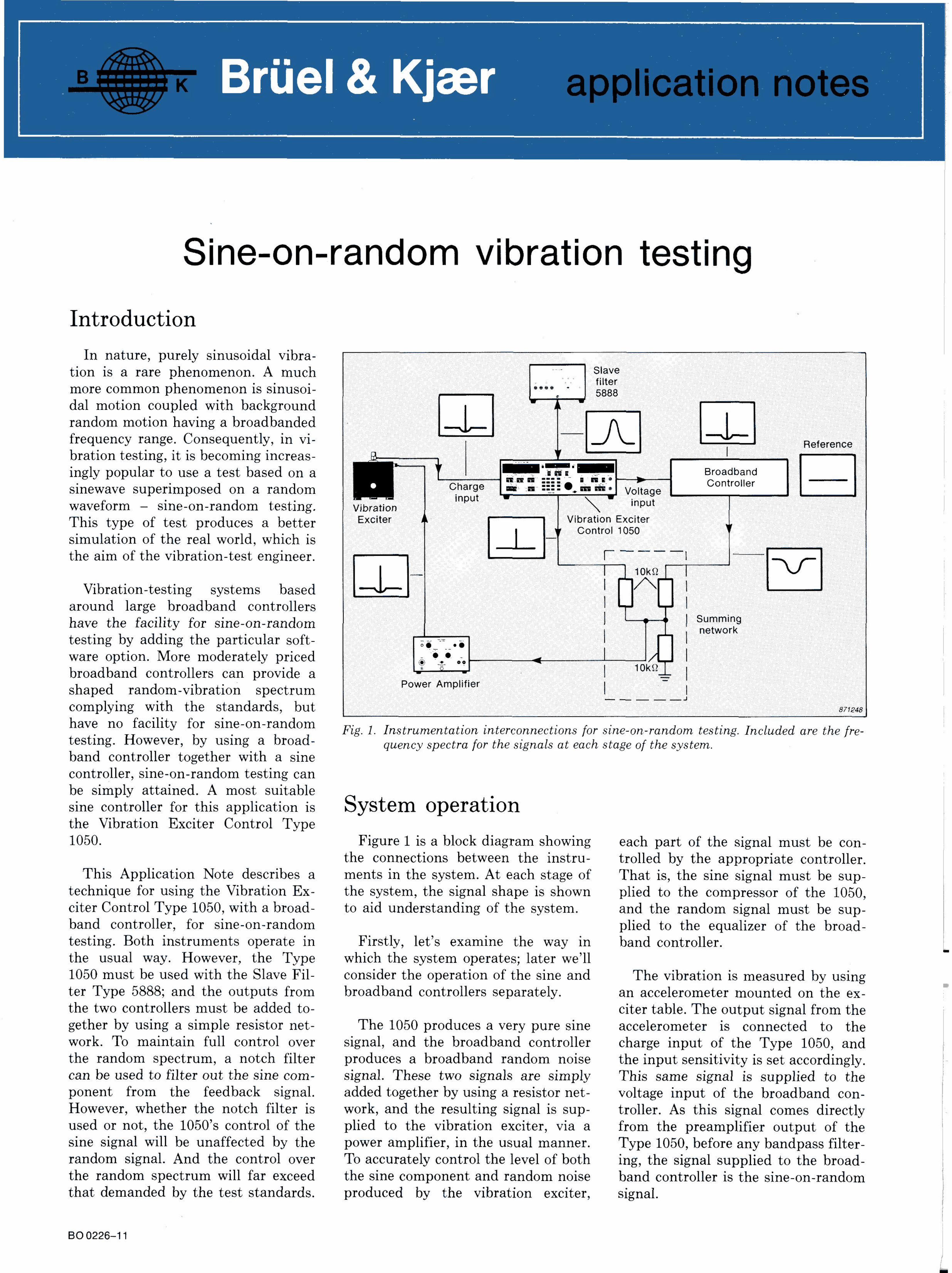
Fig. 1. Instrumentation interconnections for sine-on-random testing. Included are the frequency spectra for the signals at each stage of the system.
System operation Figure 1 is a block diagram showing each part of the signal must be con-
the connections between the instru- trolled by the appropriate controller. ments in the system. At each stage of That is, the sine signal must be sup-the system, the signal shape is shown plied to the compressor of the 1050, to aid understanding of the system. and the random signal must be sup
plied to the equalizer of the broad-Firstly, let's examine the way in band controller.
which the system operates; later we'll consider the operation of the sine and The vibration is measured by using broadband controllers separately. an accelerometer mounted on the ex
citer table. The output signal from the The 1050 produces a very pure sine accelerometer is connected to the
signal, and the broadband controller charge input of the Type 1050, and produces a broadband random noise the input sensitivity is set accordingly. signal. These two signals are simply This same signal is supplied to the added together by using a resistor net- voltage input of the broadband con-work, and the resulting signal is sup- troller. As this signal comes directly plied to the vibration exciter, via a from the preamplifier output of the power amplifier, in the usual manner. Type 1050, before any bandpass filter-To accurately control the level of both ing, the signal supplied to the broad-the sine component and random noise band controller is the sine-on-random produced by the vibration exciter, signal.
Operation of the Vibration Exciter Control Type 1050
The value of the signal supplied to the compressor of the Type 1050 is the RMS value of the sine-on-random signal. In order for the compressor to keep the level of the sine component constant, it must operate on the sine signal alone. Consequently, the input signal must be filtered using a bandpass filter.
The best filter to use with the 1050 is the Slave Filter Type 5888, as it is a two-channel filter which is controlled by the 1050. The filter is connected internally to filter the compressor and vibration meter signals of the 1050. The filter bandwidth must be chosen to be compatible with the sweep rate (if a swept-sine-on-random test is run). However, 3% is a good general purpose bandwidth.
Operation of the broadband controller
The input section of most modern broadband controllers is an FFT analyzer. The analyzer compares the measured spectrum to a reference spectrum (line by line) and calculates the output spectrum necessary to produce the desired reference spectrum. This output spectrum is transformed to a time signal, by using an inverse FFT, and is converted to an analogue signal, which is added to the sine wave by the resistor network.
Because the corrective output signal must compensate for the latest input signal, the FFT analyzer updates the frequency spectra exponentially with an adjustable time constant.
When the spectrum of the sine-on-random input to the broadband generator is measured, the sine component is represented by a small number of lines instead of one, due to leakage error. The output spectrum corresponds to the inverse of the input spectrum - it exhibits a notch represented by the same number of lines as the sine component. Consequently, after the sine signal has been added to the notched signal, the resulting sine-on-random signal has a dip on either side of the sine component. The width of the notch is dependant on the reso-
2
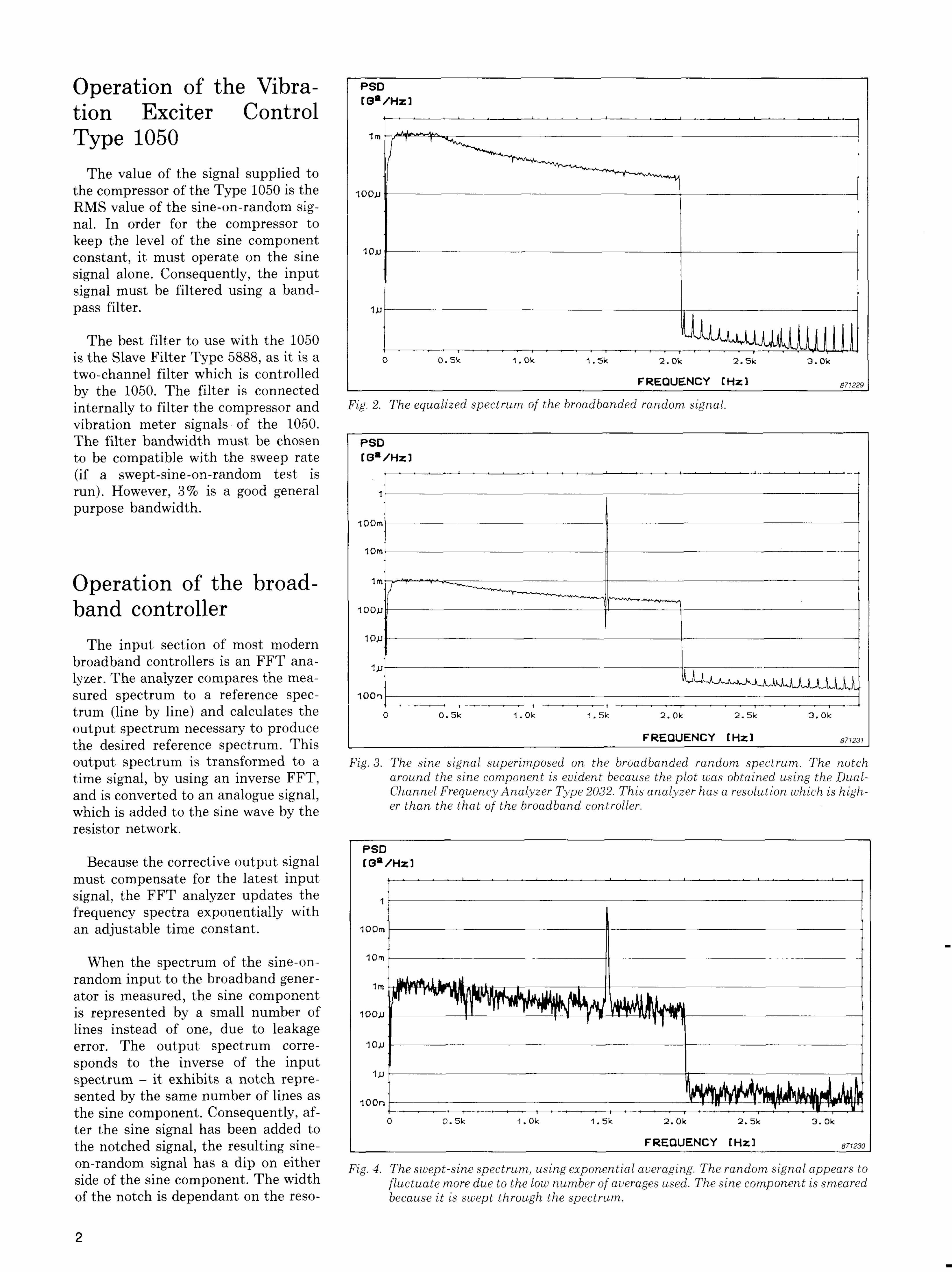
Fig. 4. The swept-sine spectrum, using exponential averaging. The random signal appears to 1 fluctuate more due to the low number of averages used. The sine component is smeared
because it is swept through the spectrum.
3 a Fig. 3. The sine signal superimposed on the broadbanded random spectrum. The notch ?T, around the sine component is evident because the plot was obtained using the Dual-i a j Channel Frequency Analyzer Type 2032. This analyzer has a resolution which is high-|i er than the that of the broadband controller.
sor and Fig. 2. The equalized spectrum of the broadbanded random signal. e 1050.
lution of the analyzer and in practice has little effect. In any case, the amplitude of the dip will not exceed the amplitude fluctuation of the spectrum.
Most broadband controllers feature an adjustable safety limit around the desired level of random noise, for instance adjustable by + / - 2 0 d B . If the measured input spectrum exceeds these limits, the controller will resort to "stand-by" or "abort". Under almost all circumstances a sine wave will exceed these limits and cause a test abortion. Therefore, the safety limits should be set so that they are insensitive to the sine frequency.
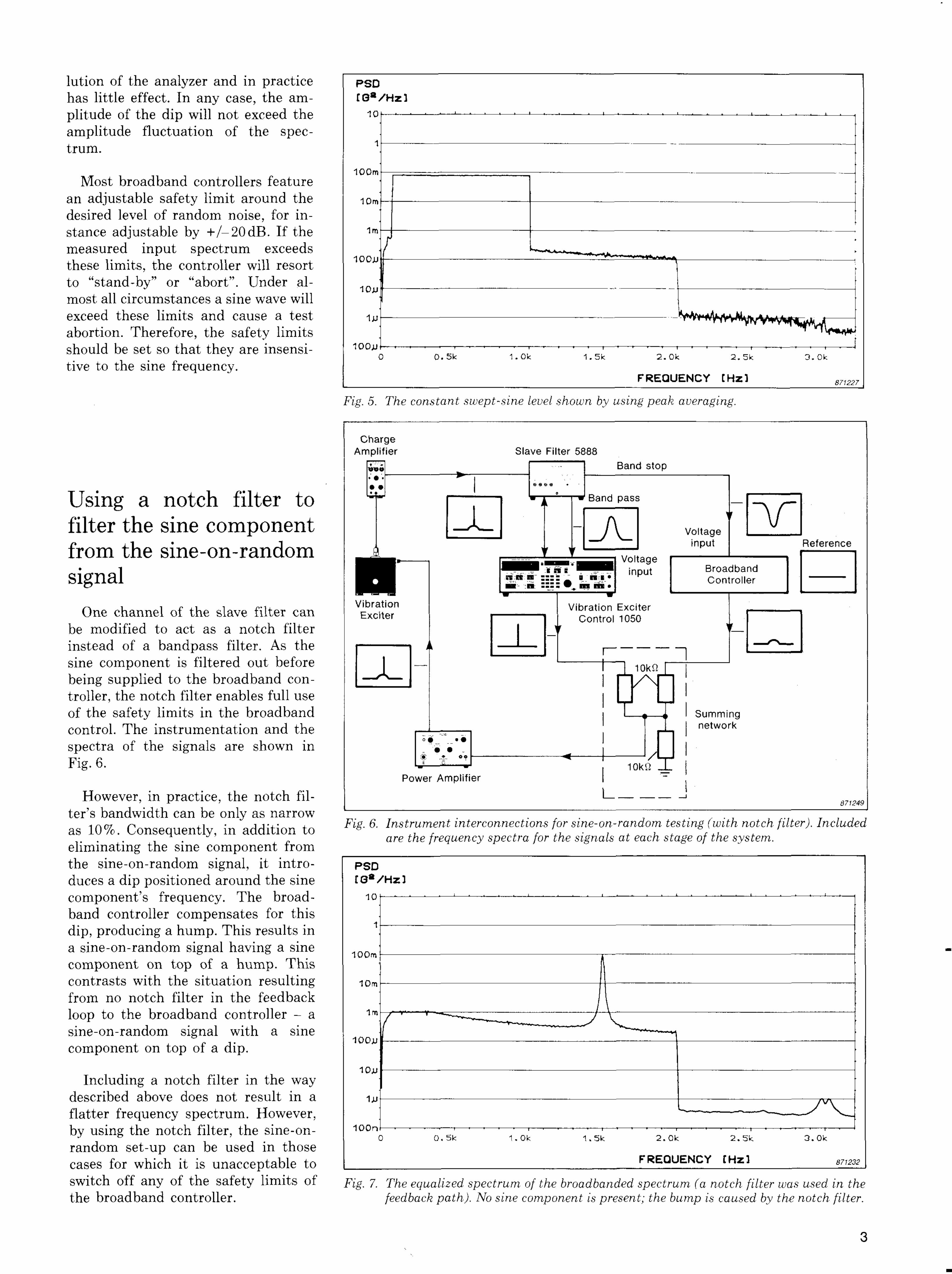
Fig. 5. The constant swept-sine level shown by using peak averaging.
Using a notch filter to filter the sine component from the sine-on-random signal
One channel of the slave filter can be modified to act as a notch filter instead of a bandpass filter. As the sine component is filtered out before being supplied to the broadband controller, the notch filter enables full use of the safety limits in the broadband control. The instrumentation and the spectra of the signals are shown in Fig. 6.
However, in practice, the notch filter's bandwidth can be only as narrow . . . . . , .
-\r\c7 n 4-1 • AA'*-' +- Fig. 6' Instrument interconnections for sine-on-random testing (with notch filter). Included as J-U /o. L/Onseciuentiy, m addition to ,, . , r ,, , , , , £,, , .. . . , . . are the frequency spectra for the signals at each stage of the system. eliminating the sine component trom the sine-on-random signal, it introduces a dip positioned around the sine component's frequency. The broadband controller compensates for this dip, producing a hump. This results in a sine-on-random signal having a sine component on top of a hump. This contrasts with the situation resulting from no notch filter in the feedback loop to the broadband controller - a sine-on-random signal with a sine component on top of a dip.
Including a notch filter in the way described above does not result in a flatter frequency spectrum. However, by using the notch filter, the sine-on-random set-up can be used in those cases for which it is unacceptable to switch off any of the safety limits or pigm 7. The equalized spectrum of the broadbanded spectrum (a notch filter was used in the the broadband controller. feedback path). No sine component is present; the bump is caused by the notch filter.
3 \
What kind of frequency spectrum should we use for the sine-on-random test?
A test spectrum is defined in terms of its power spectral density (PSD). This is sometimes called acceleration spectral density (ASD) and is shaped as defined in relevant test standards.
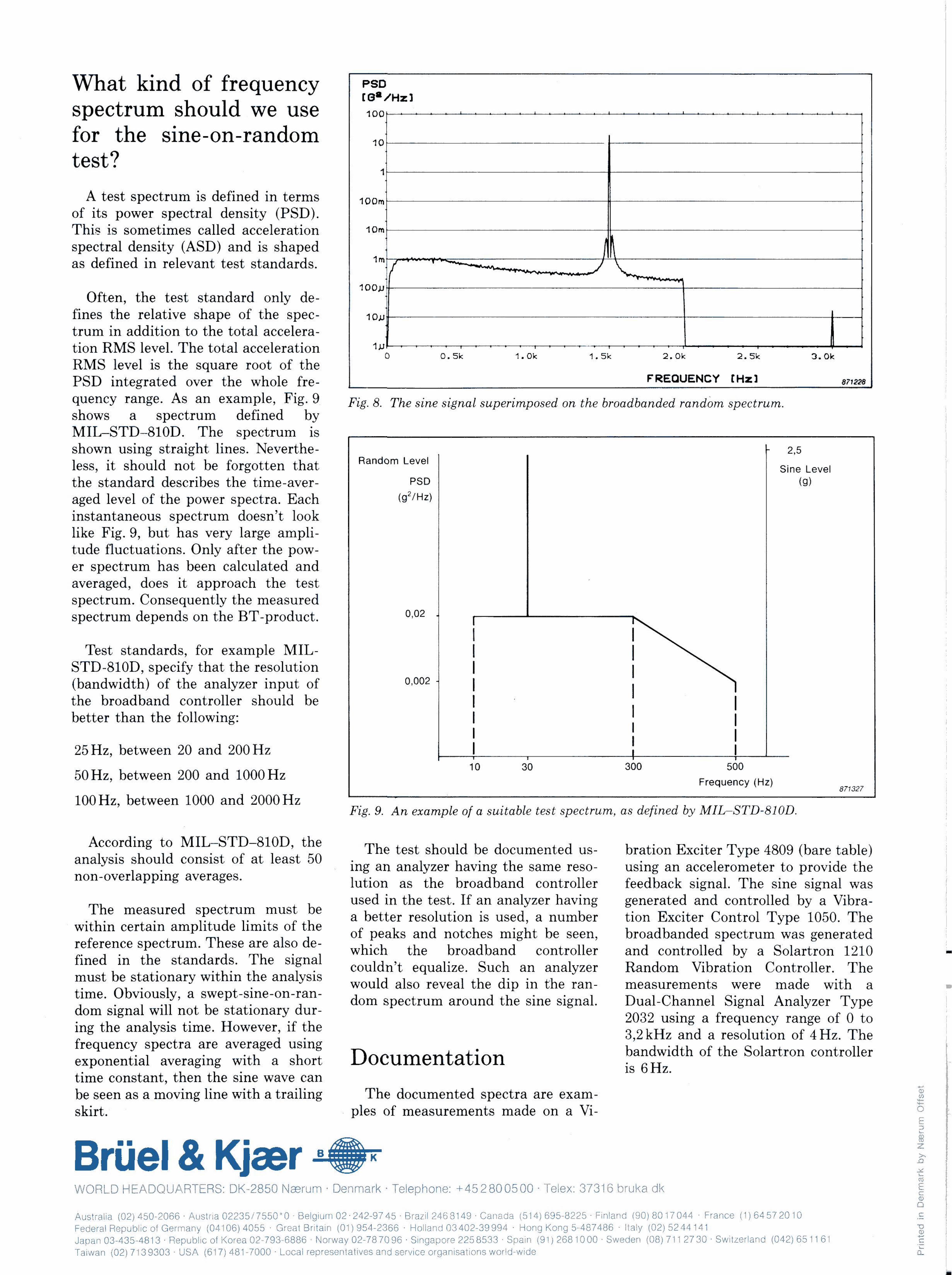
Often, the test standard only defines the relative shape of the spectrum in addition to the total acceleration RMS level. The total acceleration RMS level is the square root of the PSD integrated over the whole frequency range. As an example, r lg. y pig g ^Tie sine signal superimposed on the broadbanded random spectrum. shows a spectrum defined by MIL-STD-810D. The spectrum is shown using straight lines. Nevertheless, it should not be forgotten that the standard describes the time-averaged level of the power spectra. Each instantaneous spectrum doesn't look like Fig. 9, but has very large amplitude fluctuations. Only after the power spectrum has been calculated and averaged, does it approach the test spectrum. Consequently the measured spectrum depends on the BT-product.
Test standards, for example MIL-STD-810D, specify that the resolution (bandwidth) of the analyzer input of the broadband controller should be better than the following:
25 Hz, between 20 and 200 Hz
50 Hz, between 200 and 1000 Hz
100 Hz, between 1000 and 2000 Hz Fig. 9. An example of a suitable test spectrum, as defined by MIL-STD-810D.
; . , , , ~ c ~ , \ r ^ The test should be documented us- bration Exciter Type 4809 (bare table) analysis should consist of at least 50 , , . ,, . , , , .-> ,, J , « ing an analyzer having the same reso- using an acceierometer to provide the non-ov r ppmg v g . lution as the broadband controller feedback signal. The sine signal was
- , used in the test. If an analyzer having generated and controlled by a Vibra-. . . m ' . ,? i i , c' i a better resolution is used, a number tion Exciter Control Type 1050. The
withm certain amplitude limits of the * i i . i » ux u U J U J J ±. ^ i r T , , , or peaks and notches might be seen, broadbanded spectrum was generated
. P , , , . . which the broadband controller and controlled by a Solartron 1210 , fi f ■ couldn't equalize. Such an analyzer Random Vibration Controller. The
, , ■ y would also reveal the dip in the ran- measurements were made with a lme. vi u y, p - - - - dom spectrum around the sine signal. Dual-Channel Signal Analyzer Type
dom signal will not be stationary dur- OAOO . c c x. , fl
& , . L. TT .„ ,. 2032 using a frequency range of 0 to ing the analysis time. However, if the 0 n 1 TT , , ,. c . TT m i _ fe J t . 3,2 kHz and a resolution of 4 Hz. The frequency spectra are averaged using _ . , , . , , , £ ,, c , , , ,, n ,. , . .,, , , T^^ i - iw^^-^ + r»4--i -*-» bandwidth of the holartron controller
exponential averaging with a short L - J O G U m e n i d t l O n . ^.^r time constant, then the sine wave can be seen as a moving line with a trailing The documented spectra are exam-skirt. pies of measurements made on a Vi-