signals in particle detectors (1/2?)spagnolo/labfnsn/signal... · 7/31/15 w. riegler, particle...
TRANSCRIPT
Signals in Particle Detectors (1/2?)
7/31/15 1W. Riegler, Particle Detectors
The principle mechanisms and formulas for signal generation in particle detectors are reviewed.
As examples the signals in parallel plate chambers, wire chambers and silicon detectors are discussed.
Lecture 1: Principles and Signal Theorems
Lecture 2: Signals in Solid State Detectors, Gas Detectors (Wire Chambers, GEMs, MICROMEGAs) and Liquid Calorimeters
Werner Riegler, CERN
CERN Detector Seminar, 5.9.2008
Signals in Detectors
7/31/15 2W. Riegler, Particle Detectors
During the academic training lectures on particle detectors http://indico.cern.ch/conferenceDisplay.py?confId=24765 a few slides on signal generation principles and signal theorems created quite a lot of questions and discussions.
It seems that there is a need for a discussion of signals in particle detectors.
Although the principles and formulas are well known since a long time, there exists considerable confusion about this topic.
This is probably due to different vocabulary in different detector traditions and also due to the fact that the signal explanations in many (or most !) textbooks on particle detectors are simply wrong.
7/31/15 W. Riegler, Particle Detectors 3
From a modern detector text book:
… It is important to realize that the signals from wire chambers operating in proportional mode are primarily generated by induction due to the moving charges rather than by the collection of these charges on the electrodes …
… When a charged […] particle traverses the gap, it ionizes the atoms […]. Because of the presence of an electric field, the electrons and ions created in this process drift to their respective electrodes. The charge collected at these electrodes forms the […] signal, in contrast to gaseous detectors described above, where the signal corresponds to the current induced on the electrodes by the drifting charges (ions). …
These statements are completely wrong !
All signals in particle detectors are due to induction by moving charges. Once the charges have arrived at the electrodes the signals are ‘over’.
Creation of the Signal
Charged particles leave a trail of ions (and excited atoms) along their path: Electron-Ion pairs in gases and liquids, electron hole pairs in solids.
Photons from de-excitation are usually converted to electrons for detection.
The produced charges can be registered ! Position measurement ! Time measurement ! Tracking Detectors ....
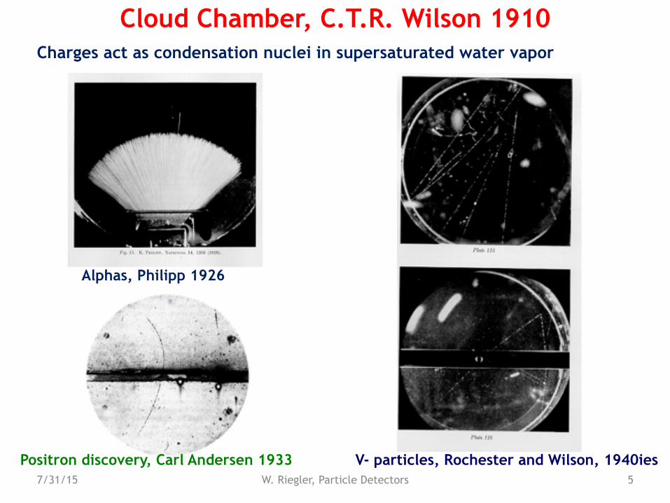
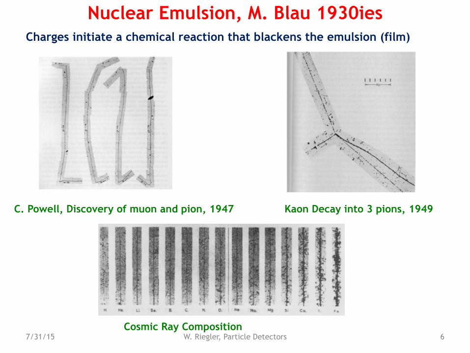
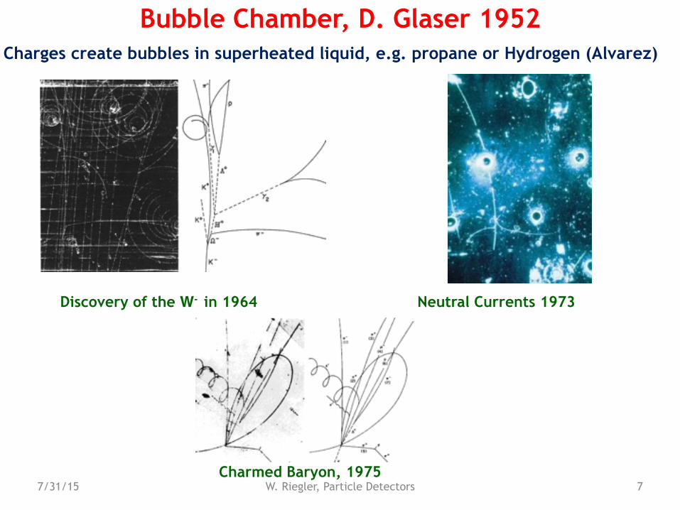
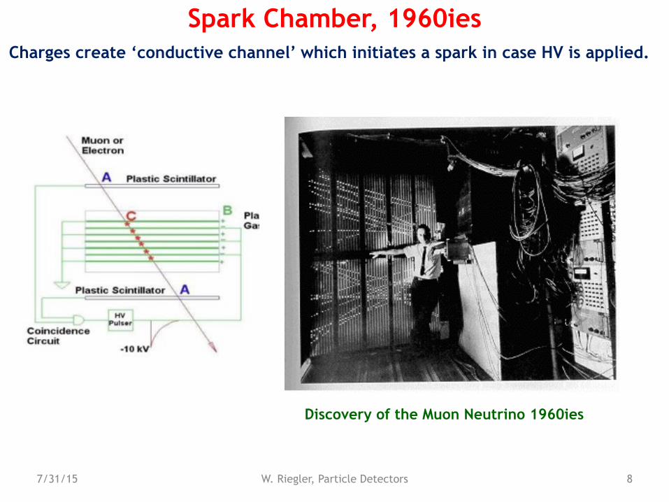
Cloud Chamber: Charges create drops ! photography. Bubble Chamber: Charges create bubbles ! photography. Emulsion: Charges ‘blacked’ the film. Spark Chamber: Charges produce a conductive channel that create a discharge ! photography
Gas and Solid State Detectors: Moving Charges (electric fields) induce electronic signals on metallic electrons that can be read by dedicated electronics.
àIn solid state detectors the charge created by the incoming particle is sufficient (not exactly correct, in Avalanche Photo Diodes one produces avalanches in a solid state detector)
àIn gas detectors (e.g. wire chamber) the charges are internally multiplied in order to provide a measurable signal.
4W. Riegler/CERN
Creation of the Signal
7/31/15 W. Riegler, Particle Detectors 5
Cloud Chamber, C.T.R. Wilson 1910Charges act as condensation nuclei in supersaturated water vapor
Alphas, Philipp 1926
Positron discovery, Carl Andersen 1933 V- particles, Rochester and Wilson, 1940ies
7/31/15 W. Riegler, Particle Detectors 6
Nuclear Emulsion, M. Blau 1930ies
C. Powell, Discovery of muon and pion, 1947 Kaon Decay into 3 pions, 1949
Cosmic Ray Composition
Charges initiate a chemical reaction that blackens the emulsion (film)
7/31/15 W. Riegler, Particle Detectors 7
Bubble Chamber, D. Glaser 1952Charges create bubbles in superheated liquid, e.g. propane or Hydrogen (Alvarez)
Discovery of the W- in 1964 Neutral Currents 1973
Charmed Baryon, 1975
7/31/15 W. Riegler, Particle Detectors 8
Spark Chamber, 1960iesCharges create ‘conductive channel’ which initiates a spark in case HV is applied.
Discovery of the Muon Neutrino 1960ies
7/31/15 W. Riegler, Particle Detectors 9
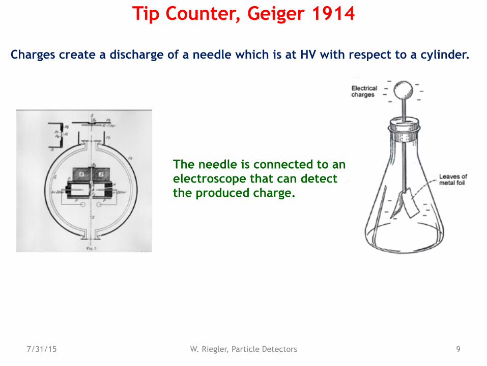
Tip Counter, Geiger 1914
Charges create a discharge of a needle which is at HV with respect to a cylinder.
The needle is connected to an electroscope that can detect the produced charge.
7/31/15 W. Riegler, Particle Detectors 10
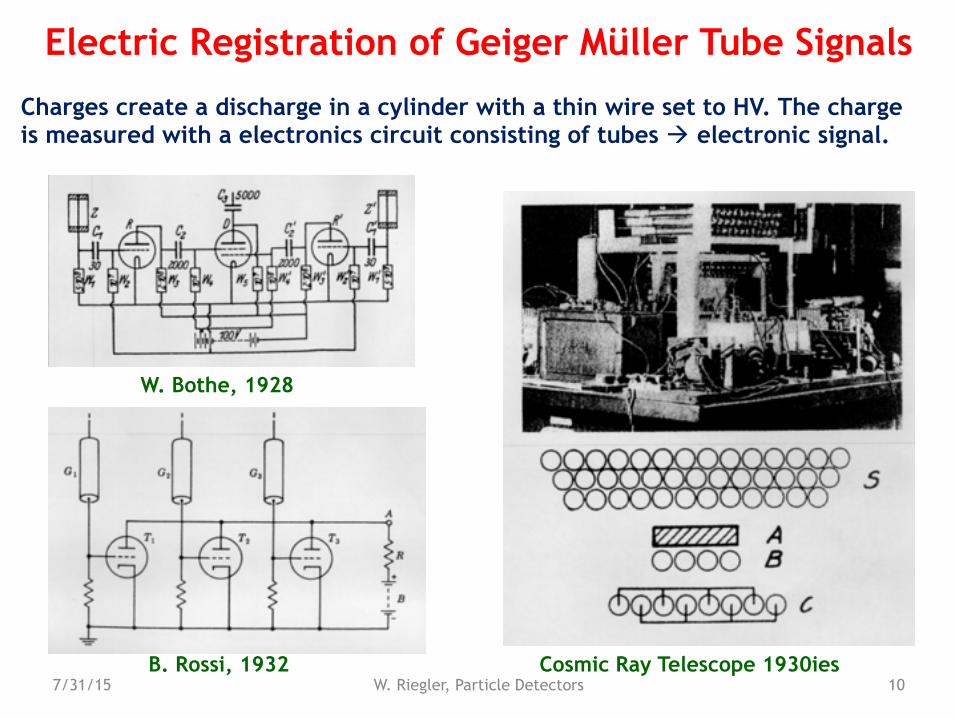
Electric Registration of Geiger Müller Tube Signals
Charges create a discharge in a cylinder with a thin wire set to HV. The charge is measured with a electronics circuit consisting of tubes ! electronic signal.
W. Bothe, 1928
B. Rossi, 1932 Cosmic Ray Telescope 1930ies
7/31/15 W. Riegler, Particle Detectors 11
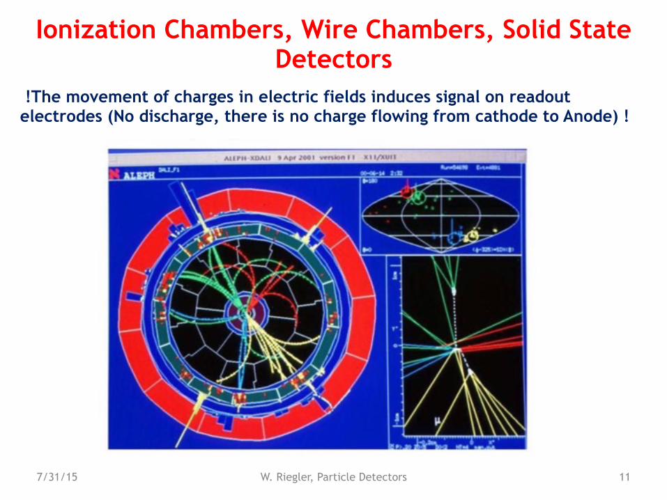
Ionization Chambers, Wire Chambers, Solid State Detectors
!The movement of charges in electric fields induces signal on readout electrodes (No discharge, there is no charge flowing from cathode to Anode) !
7/31/15 W. Riegler, Particle Detectors 12
The Principle of Signal Induction on Metal Electrodes by Moving Charges
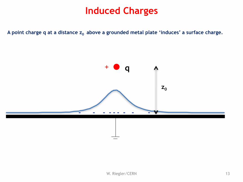
A point charge q at a distance z0 above a grounded metal plate ‘induces’ a surface charge.
13W. Riegler/CERN
Induced Charges
q
z0
+
-- - -- -- --
7/31/15 W. Riegler, Particle Detectors 14
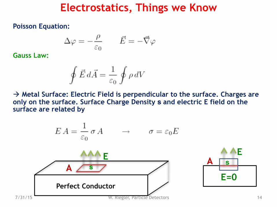
Electrostatics, Things we Know
Poisson Equation:
Gauss Law:
! Metal Surface: Electric Field is perpendicular to the surface. Charges are only on the surface. Surface Charge Density s and electric E field on the surface are related by
E
Perfect Conductor
A
E
E=0
sAs
7/31/15 W. Riegler, Particle Detectors 15
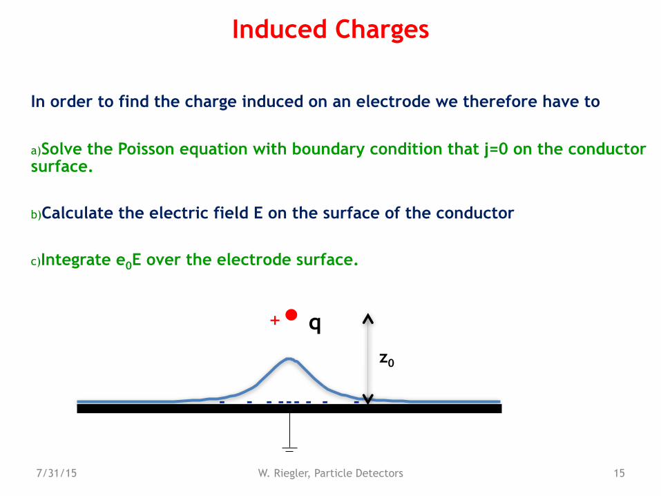
Induced Charges
In order to find the charge induced on an electrode we therefore have to
a)Solve the Poisson equation with boundary condition that j=0 on the conductor surface.
b)Calculate the electric field E on the surface of the conductor
c)Integrate e0E over the electrode surface.
qz0
+
-- - -- -- --
q
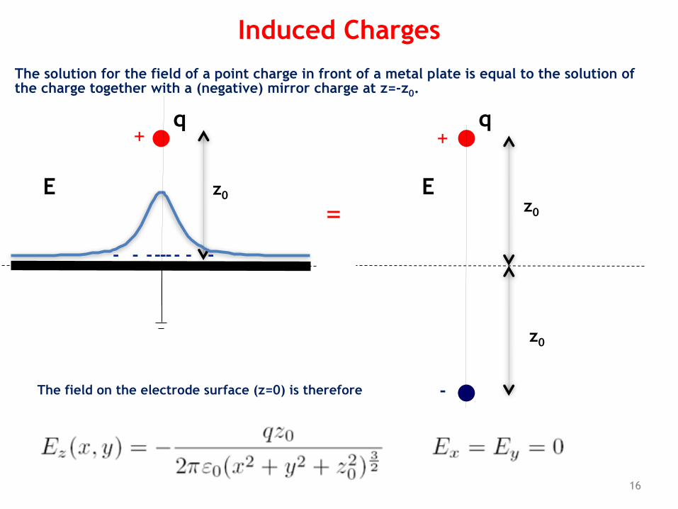
The solution for the field of a point charge in front of a metal plate is equal to the solution of the charge together with a (negative) mirror charge at z=-z0.
16
Induced Charges
+
z0
-- - -- -- --
=
q+
-
z0
z0
E E
The field on the electrode surface (z=0) is therefore
q
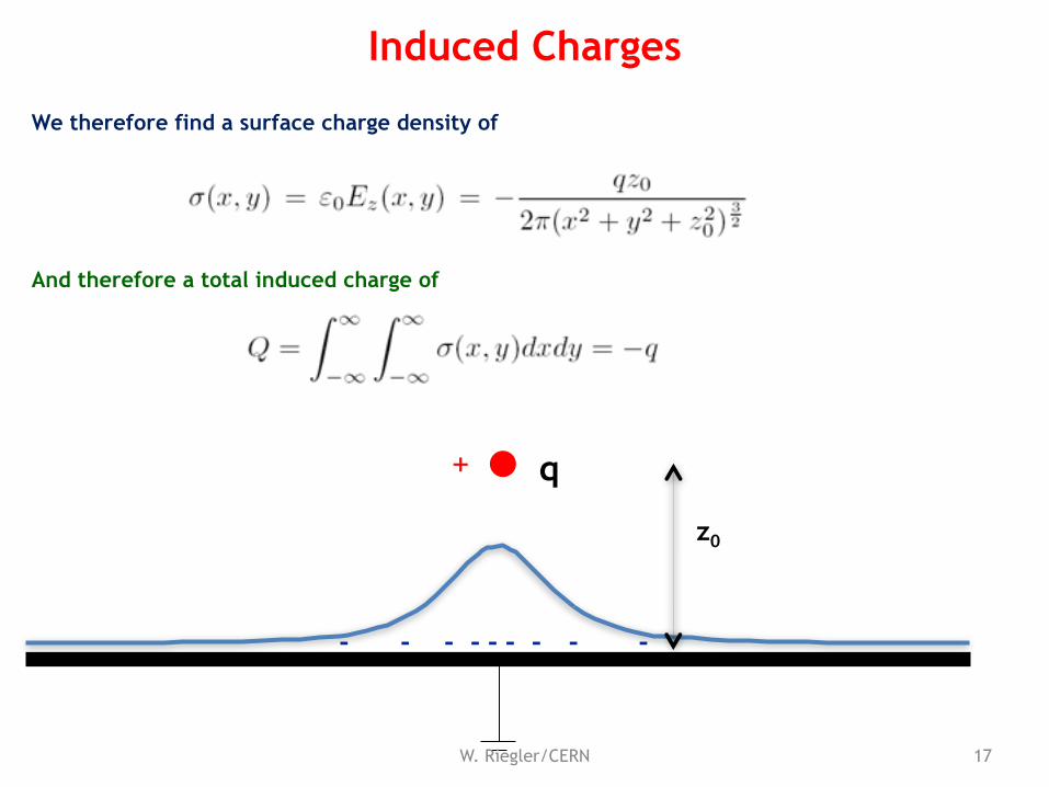
We therefore find a surface charge density of
And therefore a total induced charge of
17W. Riegler/CERN
Induced Charges
z0
+
-- - -- -- --
q
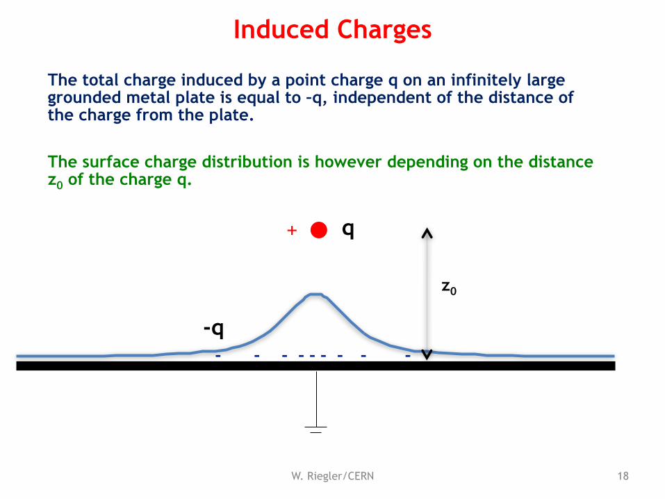
The total charge induced by a point charge q on an infinitely large grounded metal plate is equal to –q, independent of the distance of the charge from the plate.
The surface charge distribution is however depending on the distance z0 of the charge q.
18W. Riegler/CERN
Induced Charges
z0
+
-- - -- -- ---q
q
q
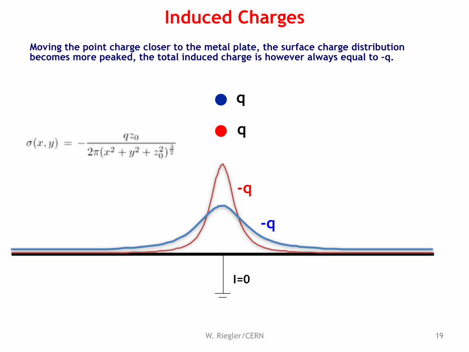
Moving the point charge closer to the metal plate, the surface charge distribution becomes more peaked, the total induced charge is however always equal to –q.
-q
-q
I=0
19W. Riegler/CERN
Induced Charges
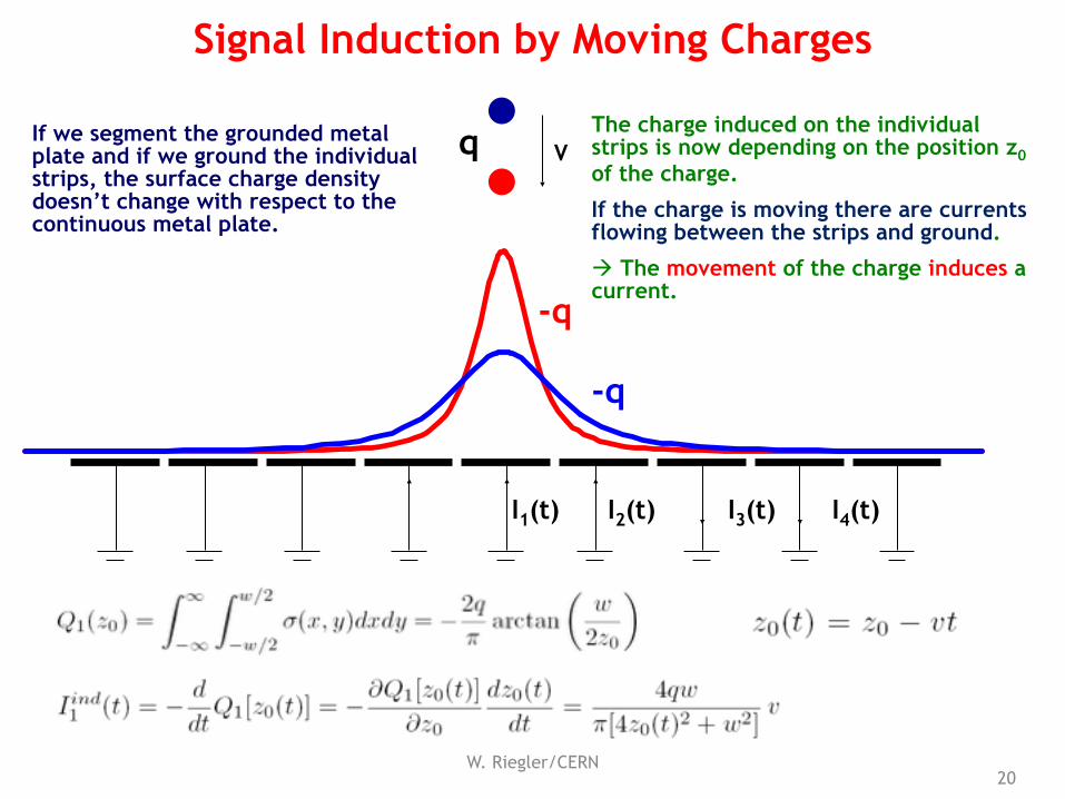
qIf we segment the grounded metal plate and if we ground the individual strips, the surface charge density doesn’t change with respect to the continuous metal plate.
-q
-q
V
I1(t) I2(t) I3(t) I4(t)
The charge induced on the individual strips is now depending on the position z0 of the charge.
If the charge is moving there are currents flowing between the strips and ground.
! The movement of the charge induces a current.
20W. Riegler/CERN
Signal Induction by Moving Charges
7/31/15 W. Riegler, Particle Detectors 21
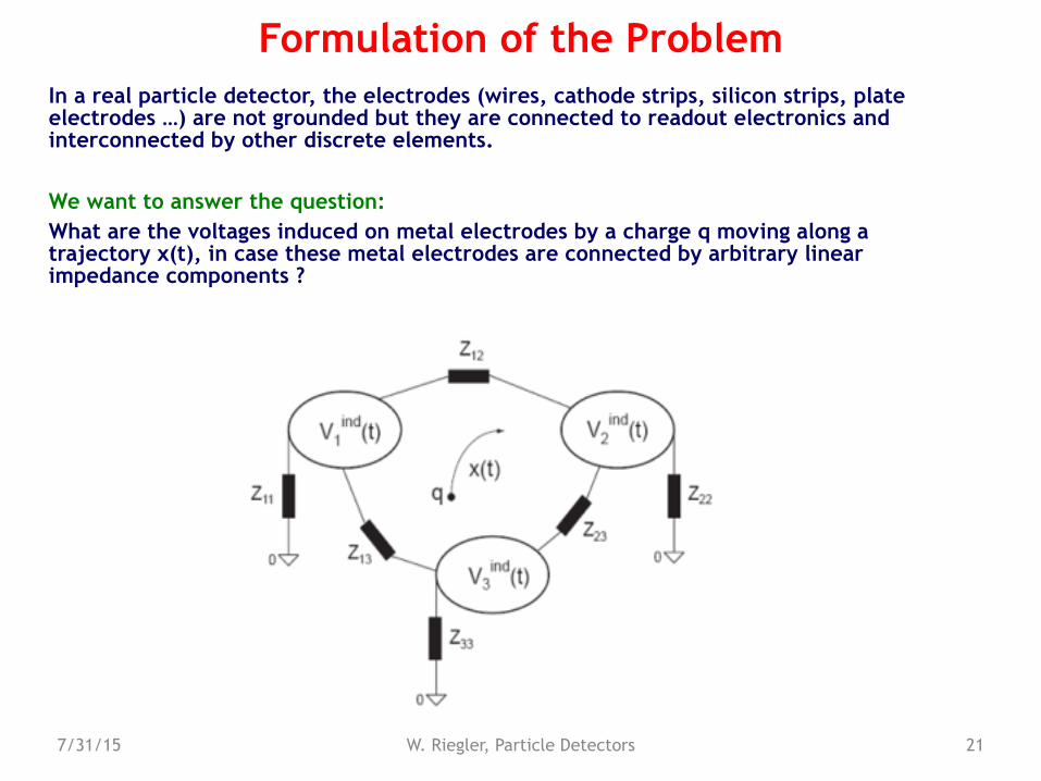
Formulation of the ProblemIn a real particle detector, the electrodes (wires, cathode strips, silicon strips, plate electrodes …) are not grounded but they are connected to readout electronics and interconnected by other discrete elements.
We want to answer the question: What are the voltages induced on metal electrodes by a charge q moving along a trajectory x(t), in case these metal electrodes are connected by arbitrary linear impedance components ?
7/31/15 W. Riegler, Particle Detectors 22
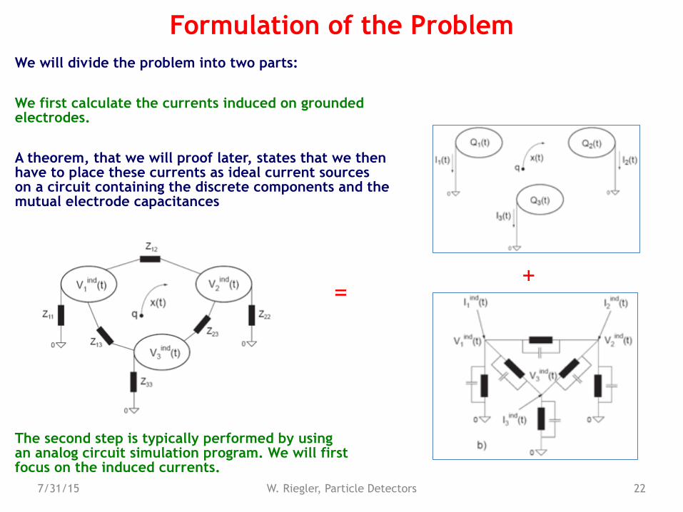
Formulation of the ProblemWe will divide the problem into two parts:
We first calculate the currents induced on grounded electrodes.
A theorem, that we will proof later, states that we then have to place these currents as ideal current sources on a circuit containing the discrete components and the mutual electrode capacitances
=+
The second step is typically performed by using an analog circuit simulation program. We will first focus on the induced currents.
7/31/15 W. Riegler, Particle Detectors 23
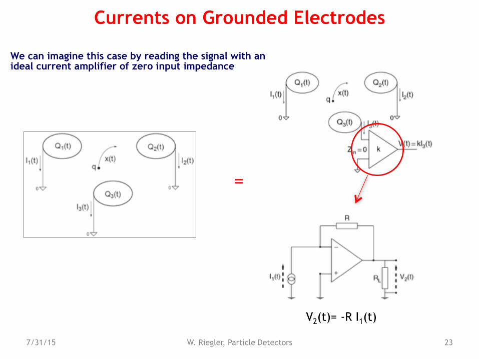
Currents on Grounded Electrodes
We can imagine this case by reading the signal with an ideal current amplifier of zero input impedance
=
V2(t)= -R I1(t)
7/31/15 W. Riegler, Particle Detectors 24
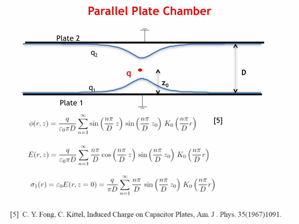
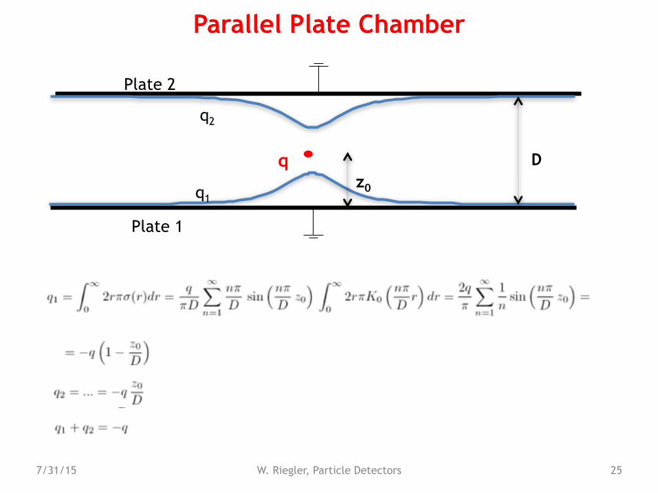
Parallel Plate Chamber
q Dz0
Plate 1
Plate 2
q2
q1
[5]
7/31/15 W. Riegler, Particle Detectors 25
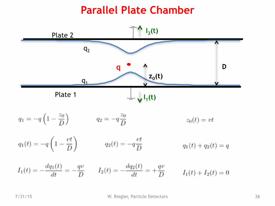
Parallel Plate Chamber
q D
Plate 1
Plate 2
q2
q1z0
7/31/15 W. Riegler, Particle Detectors 26
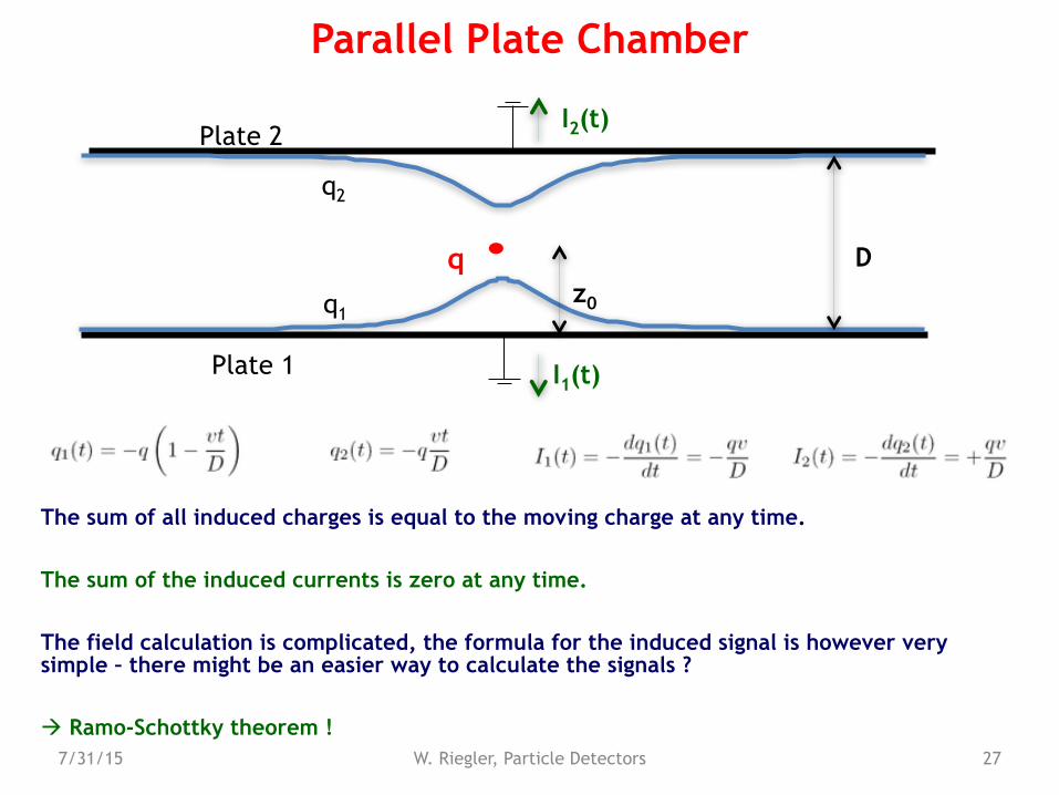
Parallel Plate Chamber
q D
Plate 1
Plate 2
q2
q1
I2(t)
I1(t)
z0(t)
7/31/15 W. Riegler, Particle Detectors 27
Parallel Plate Chamber
q Dz0
Plate 1
Plate 2
q2
q1
I2(t)
I1(t)
The sum of all induced charges is equal to the moving charge at any time.
The sum of the induced currents is zero at any time.
The field calculation is complicated, the formula for the induced signal is however very simple – there might be an easier way to calculate the signals ?
! Ramo-Schottky theorem !
7/31/15 W. Riegler, Particle Detectors 28
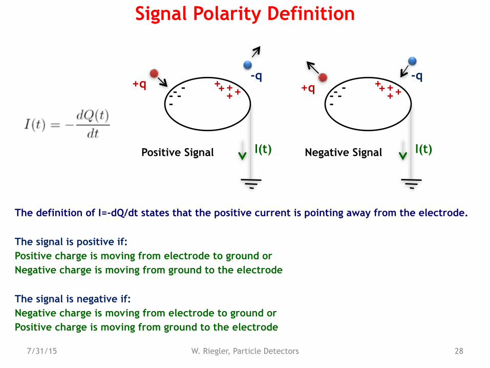
Signal Polarity Definition
I(t)
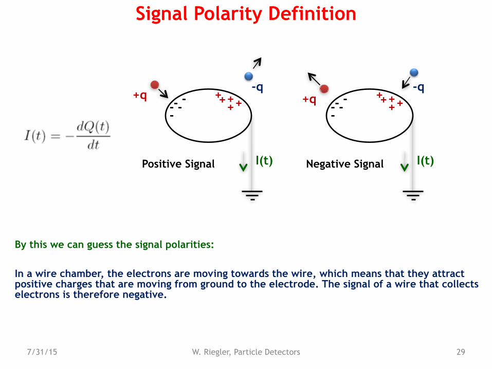
The definition of I=-dQ/dt states that the positive current is pointing away from the electrode.
The signal is positive if: Positive charge is moving from electrode to ground or Negative charge is moving from ground to the electrode
The signal is negative if: Negative charge is moving from electrode to ground or Positive charge is moving from ground to the electrode
+q----
--q
++++
+
I(t)
+q----
--q
++++
+
Positive Signal Negative Signal
7/31/15 W. Riegler, Particle Detectors 29
Signal Polarity Definition
I(t)
By this we can guess the signal polarities:
In a wire chamber, the electrons are moving towards the wire, which means that they attract positive charges that are moving from ground to the electrode. The signal of a wire that collects electrons is therefore negative.
+q----
--q
++++
+
I(t)
+q----
--q
++++
+
Positive Signal Negative Signal
7/31/15 W. Riegler, Particle Detectors 30
Sum of Induced Charges and Currents
E
q
A
V
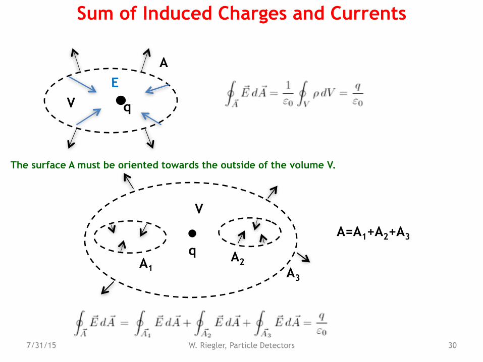
The surface A must be oriented towards the outside of the volume V.
q
A3
V
A1A2
A=A1+A2+A3
7/31/15 W. Riegler, Particle Detectors 31
Sum of Induced Charges and Currents
qQ3
V
Q1Q2
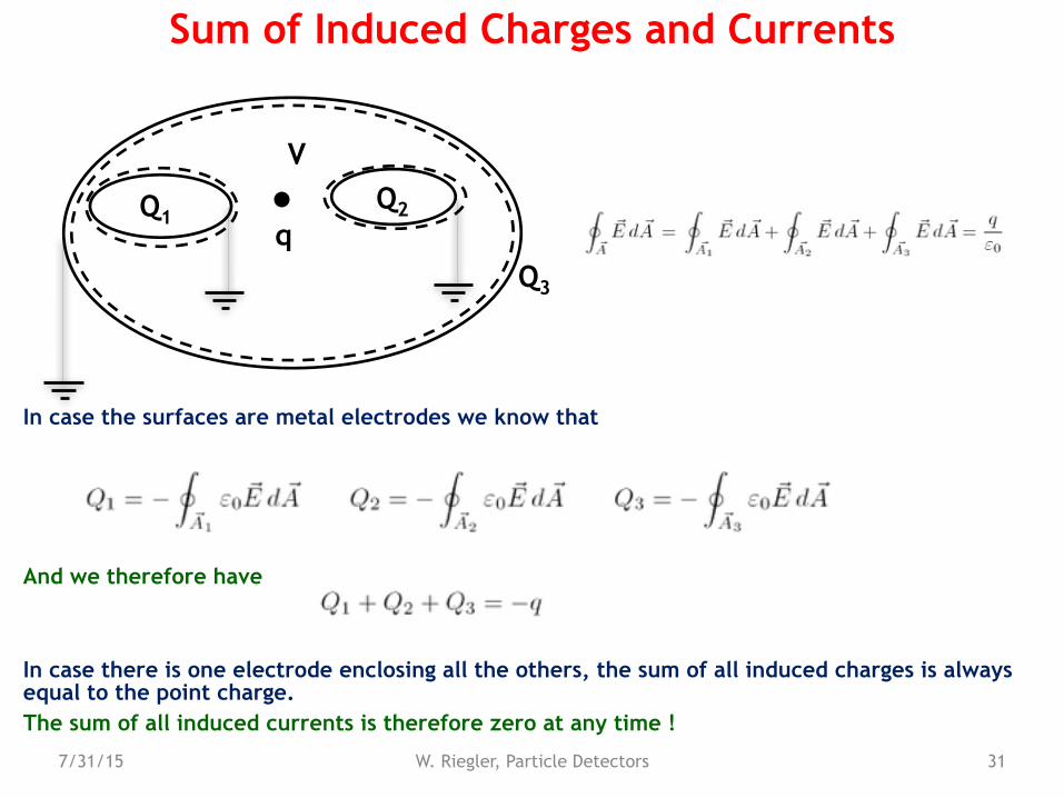
In case the surfaces are metal electrodes we know that
And we therefore have
In case there is one electrode enclosing all the others, the sum of all induced charges is always equal to the point charge. The sum of all induced currents is therefore zero at any time !

7/31/15 W. Riegler, Particle Detectors 32
Charged Electrodes
Setting the three electrodes to potentials V1, V2, V3 results in charges Q1, Q2, Q3.
In order to find them we have to solve the Laplace equation
with boundary condition
And the calculate
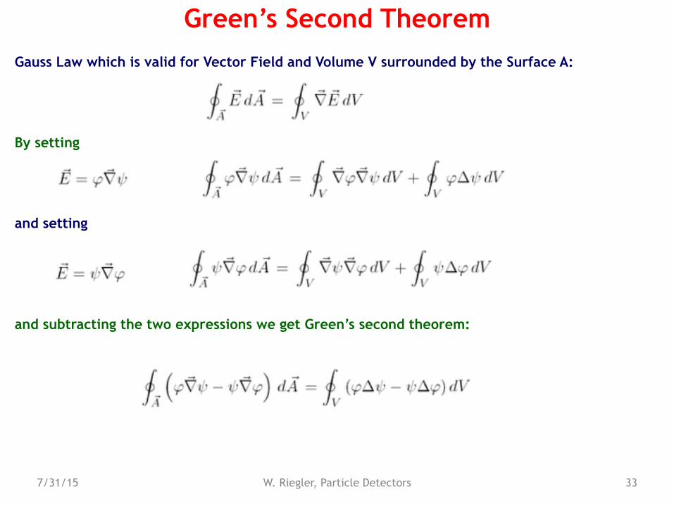
Gauss Law which is valid for Vector Field and Volume V surrounded by the Surface A:
By setting
and setting
and subtracting the two expressions we get Green’s second theorem:
7/31/15 W. Riegler, Particle Detectors 33
Green’s Second Theorem
7/31/15 W. Riegler, Particle Detectors 34
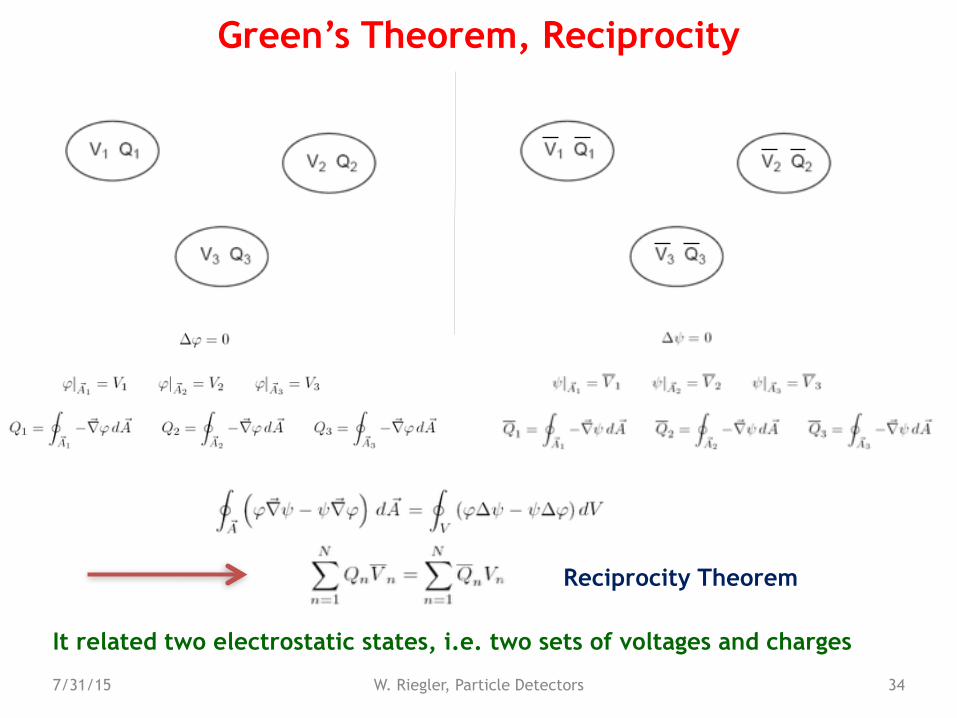
Green’s Theorem, Reciprocity
Reciprocity Theorem
It related two electrostatic states, i.e. two sets of voltages and charges
7/31/15 W. Riegler, Particle Detectors 35
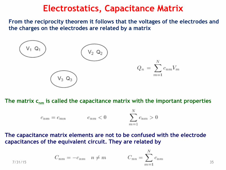
Electrostatics, Capacitance Matrix From the reciprocity theorem it follows that the voltages of the electrodes and the charges on the electrodes are related by a matrix
The matrix cnm is called the capacitance matrix with the important properties
The capacitance matrix elements are not to be confused with the electrode capacitances of the equivalent circuit. They are related by
Using the reciprocity theorem we get
7/31/15 W. Riegler, Particle Detectors 36
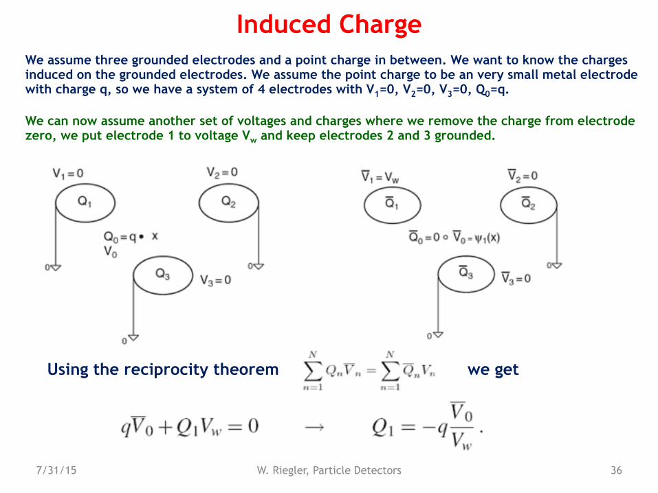
Induced ChargeWe assume three grounded electrodes and a point charge in between. We want to know the charges induced on the grounded electrodes. We assume the point charge to be an very small metal electrode with charge q, so we have a system of 4 electrodes with V1=0, V2=0, V3=0, Q0=q.
We can now assume another set of voltages and charges where we remove the charge from electrode zero, we put electrode 1 to voltage Vw and keep electrodes 2 and 3 grounded.
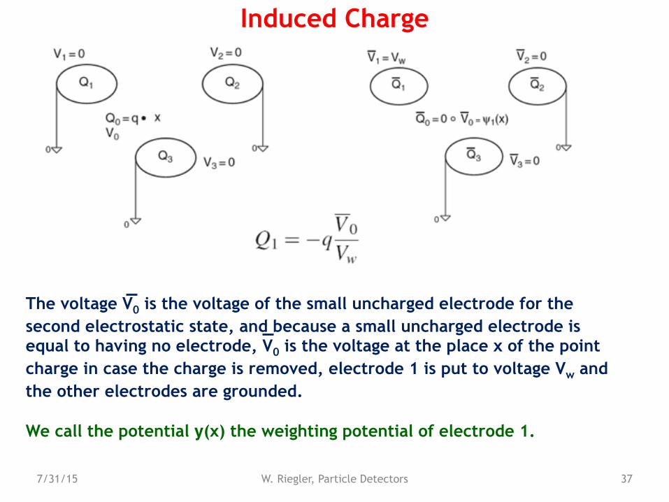
The voltage V0 is the voltage of the small uncharged electrode for the second electrostatic state, and because a small uncharged electrode is equal to having no electrode, V0 is the voltage at the place x of the point charge in case the charge is removed, electrode 1 is put to voltage Vw and the other electrodes are grounded.
We call the potential y(x) the weighting potential of electrode 1.
7/31/15 W. Riegler, Particle Detectors 37
Induced Charge
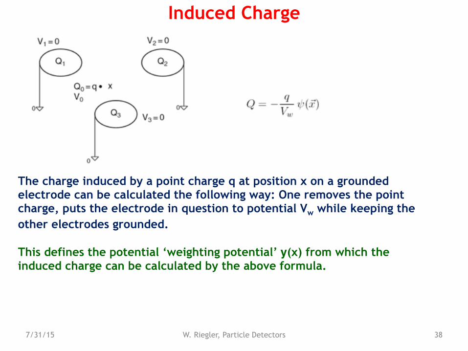
The charge induced by a point charge q at position x on a grounded electrode can be calculated the following way: One removes the point charge, puts the electrode in question to potential Vw while keeping the other electrodes grounded.
This defines the potential ‘weighting potential’ y(x) from which the induced charge can be calculated by the above formula.
7/31/15 W. Riegler, Particle Detectors 38
Induced Charge
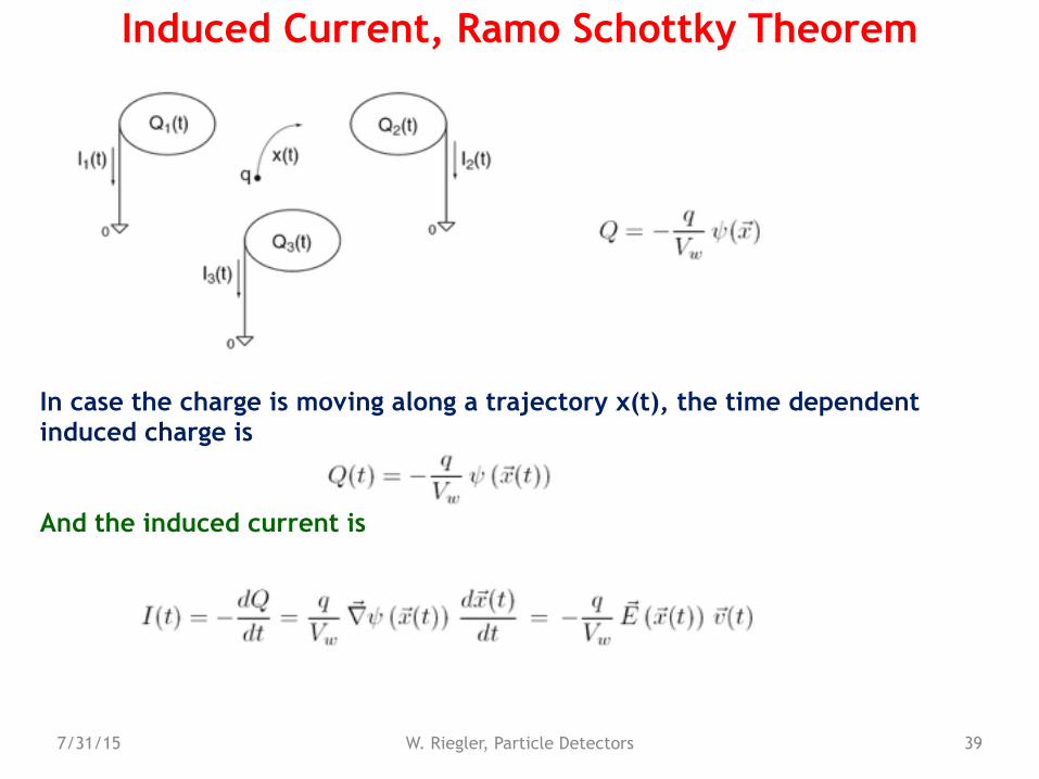
In case the charge is moving along a trajectory x(t), the time dependent induced charge is
And the induced current is
7/31/15 W. Riegler, Particle Detectors 39
Induced Current, Ramo Schottky Theorem

The current induced on a grounded electrode n by a moving point charge q is given by
Where the weighting field En is defined by removing the point charge, setting the electrode in question to potential Vw and keeping the other electrodes grounded.
Removing the charge means that we just have to solve the Laplace equation and not the Poisson equation !
7/31/15 W. Riegler, Particle Detectors 40
Induced Charge
7/31/15 W. Riegler, Particle Detectors 41
Parallel Plate Chamber
q Dz0
Plate 1
Plate 2
q2
q1
I2(t)
I1(t)
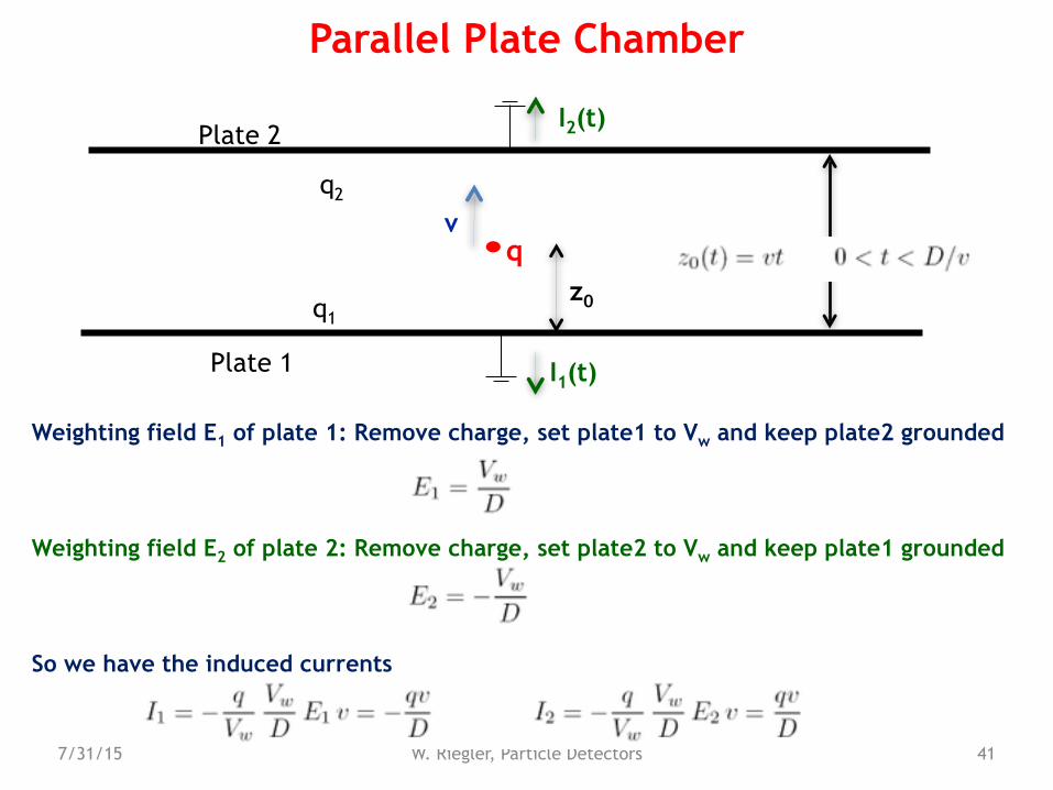
Weighting field E1 of plate 1: Remove charge, set plate1 to Vw and keep plate2 grounded
Weighting field E2 of plate 2: Remove charge, set plate2 to Vw and keep plate1 grounded
So we have the induced currents
v
7/31/15 W. Riegler, Particle Detectors 42
Arguing with Energy ? Not a good Idea !
q D
V0
dZE=V0/D
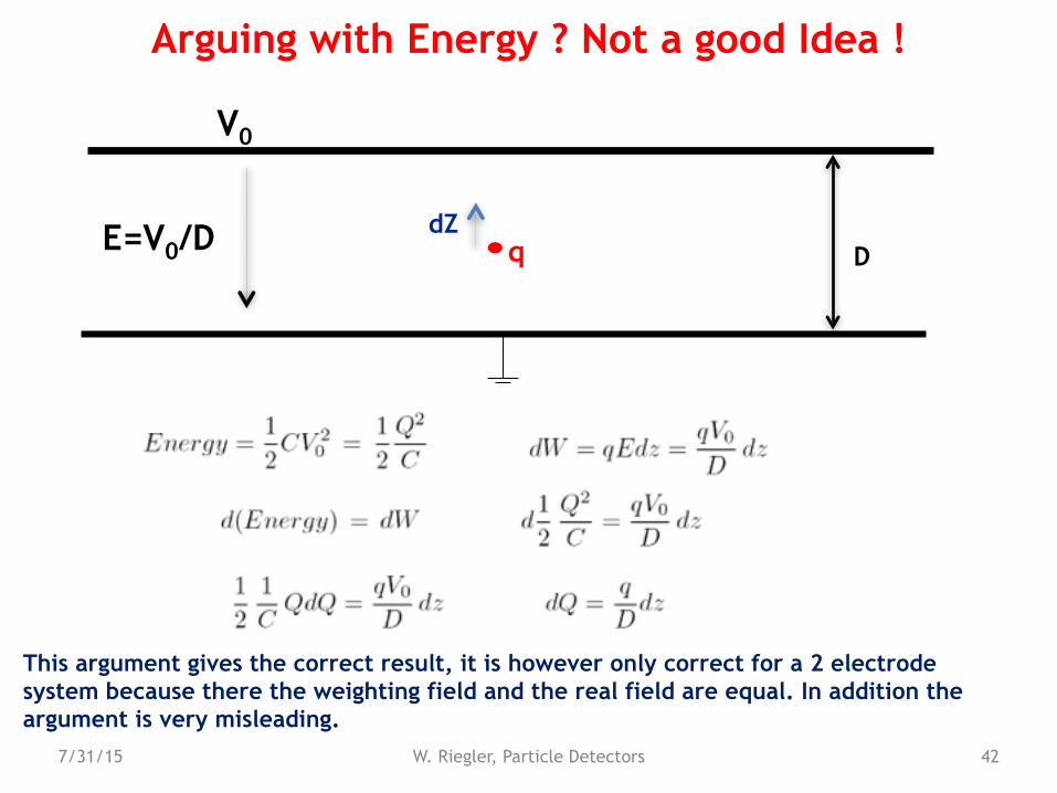
This argument gives the correct result, it is however only correct for a 2 electrode system because there the weighting field and the real field are equal. In addition the argument is very misleading.
7/31/15 W. Riegler, Particle Detectors 43
Arguing with Energy ? Not a good Idea !
q Ddz
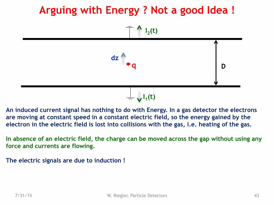
An induced current signal has nothing to do with Energy. In a gas detector the electrons are moving at constant speed in a constant electric field, so the energy gained by the electron in the electric field is lost into collisions with the gas, i.e. heating of the gas.
In absence of an electric field, the charge can be moved across the gap without using any force and currents are flowing.
The electric signals are due to induction !
I2(t)
I1(t)
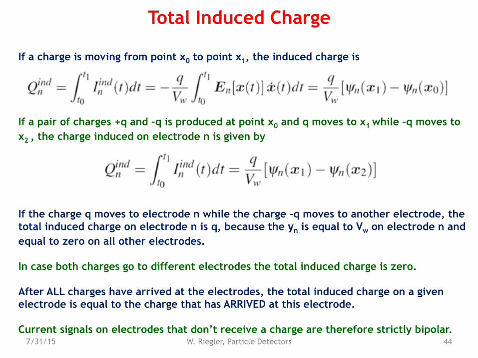
If a charge is moving from point x0 to point x1, the induced charge is
If a pair of charges +q and -q is produced at point x0 and q moves to x1 while –q moves to x2 , the charge induced on electrode n is given by
If the charge q moves to electrode n while the charge –q moves to another electrode, the total induced charge on electrode n is q, because the yn is equal to Vw on electrode n and equal to zero on all other electrodes.
In case both charges go to different electrodes the total induced charge is zero.
After ALL charges have arrived at the electrodes, the total induced charge on a given electrode is equal to the charge that has ARRIVED at this electrode.
Current signals on electrodes that don’t receive a charge are therefore strictly bipolar.7/31/15 W. Riegler, Particle Detectors 44
Total Induced Charge
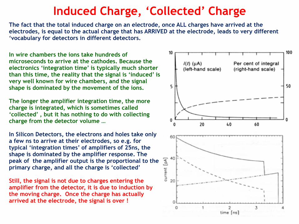
In wire chambers the ions take hundreds of microseconds to arrive at the cathodes. Because the electronics ‘integration time’ is typically much shorter than this time, the reality that the signal is ‘induced’ is very well known for wire chambers, and the signal shape is dominated by the movement of the ions.
The longer the amplifier integration time, the more charge is integrated, which is sometimes called ‘collected’ , but it has nothing to do with collecting charge from the detector volume …
In Silicon Detectors, the electrons and holes take only a few ns to arrive at their electrodes, so e.g. for typical ‘integration times’ of amplifiers of 25ns, the shape is dominated by the amplifier response. The peak of the amplifier output is the proportional to the primary charge, and all the charge is ‘collected’
Still, the signal is not due to charges entering the amplifier from the detector, it is due to induction by the moving charge. Once the charge has actually arrived at the electrode, the signal is over !
45
Induced Charge, ‘Collected’ ChargeThe fact that the total induced charge on an electrode, once ALL charges have arrived at the electrodes, is equal to the actual charge that has ARRIVED at the electrode, leads to very different ‘vocabulary for detectors in different detectors.
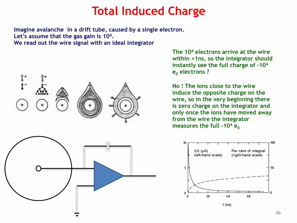
Imagine avalanche in a drift tube, caused by a single electron. Let’s assume that the gas gain is 104. We read out the wire signal with an ideal integrator
46
Total Induced Charge
b
The 104 electrons arrive at the wire within <1ns, so the integrator should instantly see the full charge of -104 e0 electrons ?
No ! The ions close to the wire induce the opposite charge on the wire, so in the very beginning there is zero charge on the integrator and only once the Ions have moved away from the wire the integrator measures the full -104 e0
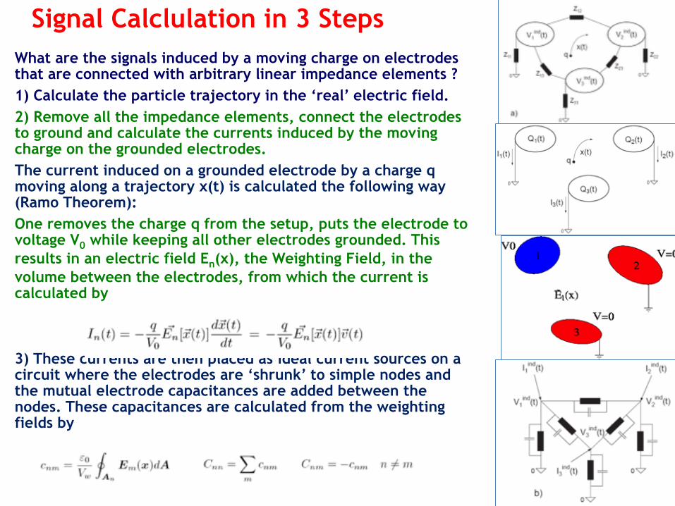
What are the signals induced by a moving charge on electrodes that are connected with arbitrary linear impedance elements ? 1) Calculate the particle trajectory in the ‘real’ electric field. 2) Remove all the impedance elements, connect the electrodes to ground and calculate the currents induced by the moving charge on the grounded electrodes. The current induced on a grounded electrode by a charge q moving along a trajectory x(t) is calculated the following way (Ramo Theorem): One removes the charge q from the setup, puts the electrode to voltage V0 while keeping all other electrodes grounded. This results in an electric field En(x), the Weighting Field, in the volume between the electrodes, from which the current is calculated by
3) These currents are then placed as ideal current sources on a circuit where the electrodes are ‘shrunk’ to simple nodes and the mutual electrode capacitances are added between the nodes. These capacitances are calculated from the weighting fields by
47
Signal Calclulation in 3 Steps
7/31/15 W. Riegler, Particle Detectors 48
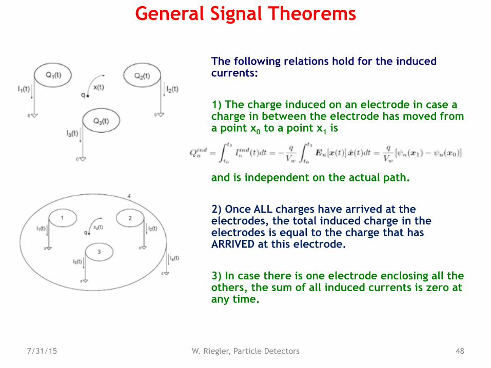
The following relations hold for the induced currents:
1) The charge induced on an electrode in case a charge in between the electrode has moved from a point x0 to a point x1 is
and is independent on the actual path.
2) Once ALL charges have arrived at the electrodes, the total induced charge in the electrodes is equal to the charge that has ARRIVED at this electrode.
3) In case there is one electrode enclosing all the others, the sum of all induced currents is zero at any time.
General Signal Theorems
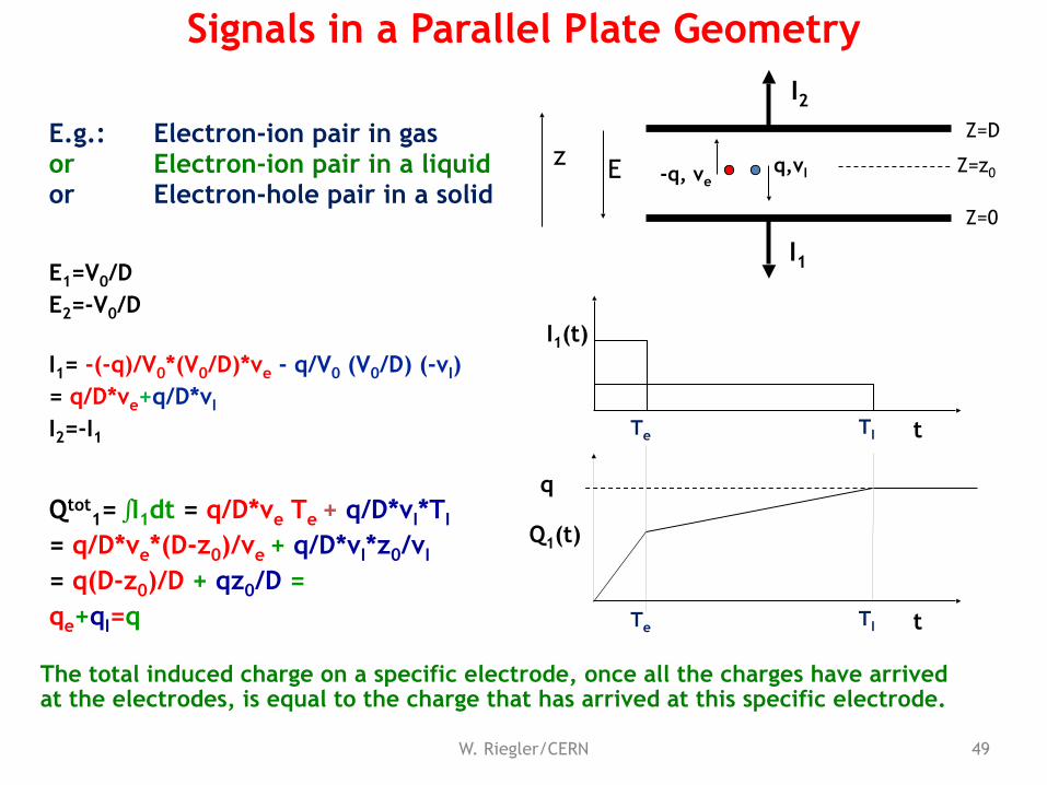
E.g.: Electron-ion pair in gas or Electron-ion pair in a liquid or Electron-hole pair in a solid
The total induced charge on a specific electrode, once all the charges have arrived at the electrodes, is equal to the charge that has arrived at this specific electrode.
E1=V0/D E2=-V0/D
I1= -(-q)/V0*(V0/D)*ve - q/V0 (V0/D) (-vI) = q/D*ve+q/D*vI
I2=-I1
Qtot1= ∫I1dt = q/D*ve Te + q/D*vI*TI
= q/D*ve*(D-z0)/ve + q/D*vI*z0/vI
= q(D-z0)/D + qz0/D = qe+qI=q
Q1(t)
tTe TI
I1
I2
q,vI-q, ve
zZ=D
Z=0
Z=z0E
49W. Riegler/CERN
Signals in a Parallel Plate Geometry
I1(t)
tTe TI
q
Wire Chamber Signals
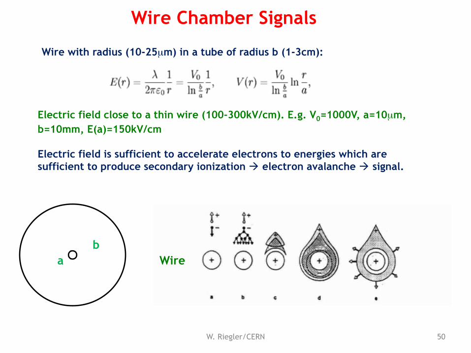
Electric field close to a thin wire (100-300kV/cm). E.g. V0=1000V, a=10µm, b=10mm, E(a)=150kV/cm
Electric field is sufficient to accelerate electrons to energies which are sufficient to produce secondary ionization ! electron avalanche ! signal.
Wire with radius (10-25µm) in a tube of radius b (1-3cm):
W. Riegler/CERN 50
bb
a Wire
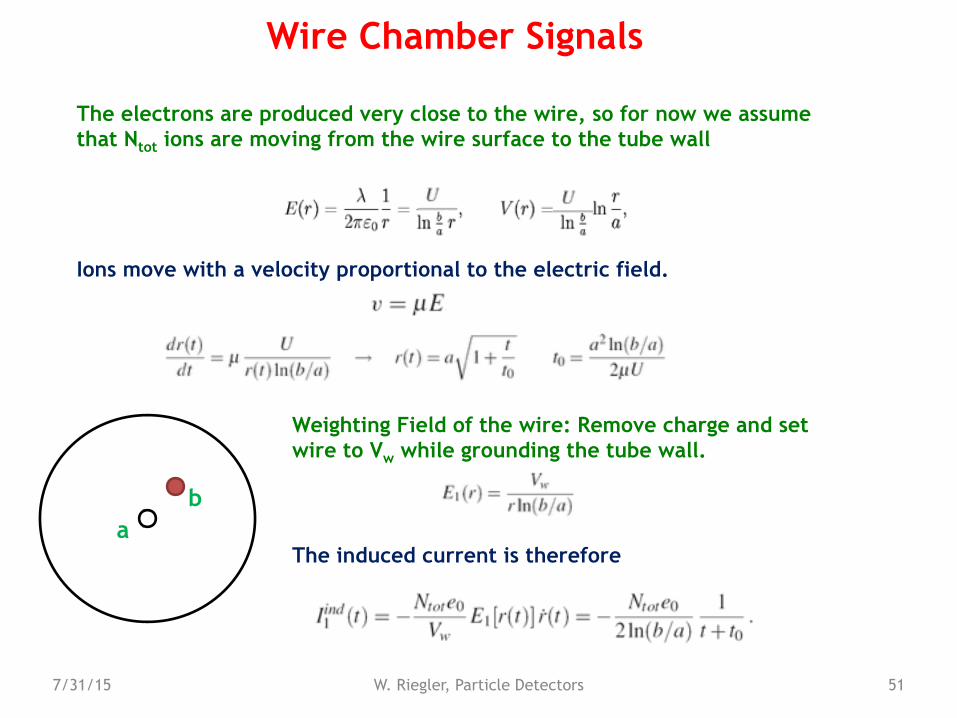
Weighting Field of the wire: Remove charge and set wire to Vw while grounding the tube wall.
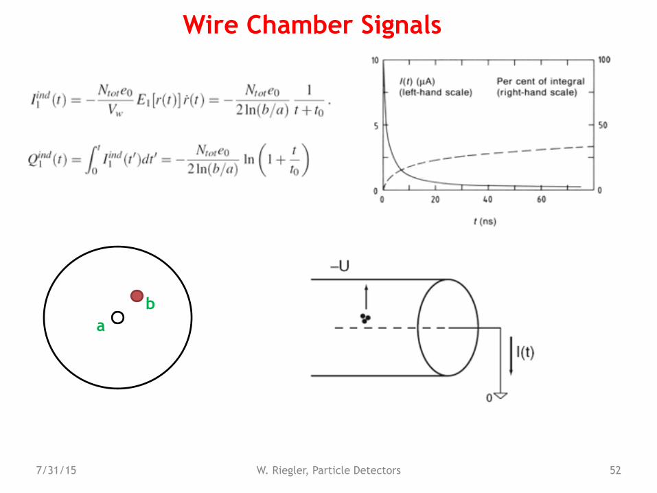
The induced current is therefore
7/31/15 W. Riegler, Particle Detectors 51
Wire Chamber Signals
The electrons are produced very close to the wire, so for now we assume that Ntot ions are moving from the wire surface to the tube wall
Ions move with a velocity proportional to the electric field.
bb
a
7/31/15 W. Riegler, Particle Detectors 52
Wire Chamber Signals
bb
a
W. Riegler/CERN 53
p+
n-
n+
-V
dxh xehole
electron
x0xE
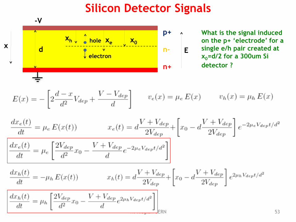
Silicon Detector Signals
What is the signal induced on the p+ ‘electrode’ for a single e/h pair created at x0=d/2 for a 300um Si detector ?
W. Riegler/CERN 54
p+
n-
n+
-V
dxh xehole
electron
x0xE
Silicon Detector Signals
W. Riegler/CERN 55
p+
n-
n+
-V
dxh xehole
electron
x0x
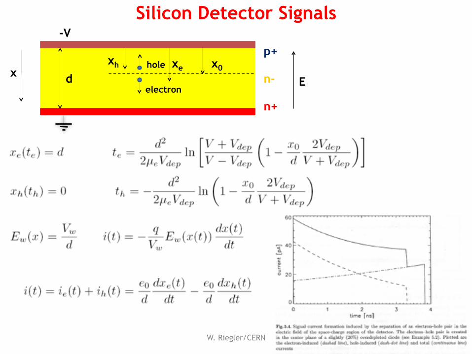
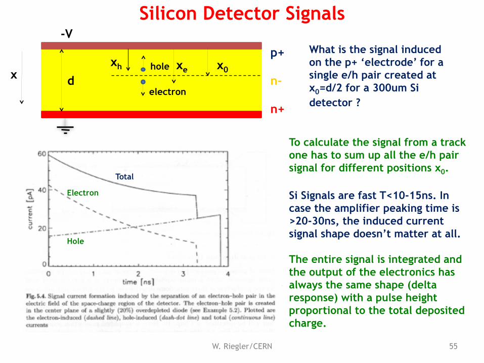
What is the signal induced on the p+ ‘electrode’ for a single e/h pair created at x0=d/2 for a 300um Si detector ?
Electron
Hole
Total
To calculate the signal from a track one has to sum up all the e/h pair signal for different positions x0.
Si Signals are fast T<10-15ns. In case the amplifier peaking time is >20-30ns, the induced current signal shape doesn’t matter at all.
The entire signal is integrated and the output of the electronics has always the same shape (delta response) with a pulse height proportional to the total deposited charge.
Silicon Detector Signals
W. Riegler/CERN 56
Next Time
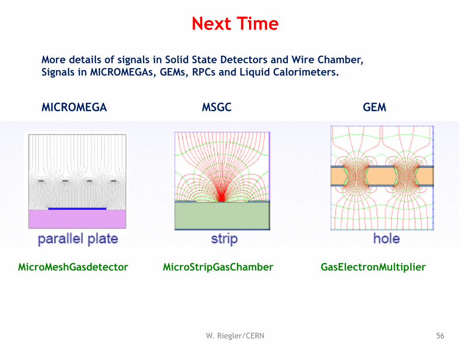
MICROMEGA MSGC GEM
MicroMeshGasdetector MicroStripGasChamber GasElectronMultiplier
More details of signals in Solid State Detectors and Wire Chamber, Signals in MICROMEGAs, GEMs, RPCs and Liquid Calorimeters.
7/31/15 W. Riegler, Particle Detectors 57
Conclusion
This principle of signal generation is identical for Solid State Detectors, Gas Detectors and Liquid Detectors.
The signals are due to charges (currents) induced on metal electrodes by moving charges.
The easiest way to calculate signals induced by moving charges on metal electrodes is the use of Weighting fields (Ramo – Schottky theorem) for calculation of currents induced on grounded electrodes.
These currents can then be placed as ideal current sources on an equivalent circuit diagram representing the detector.