sigma ii series servo system user’s manual - bg automationbgautomation.net/downloads/yaskawa sigma...
TRANSCRIPT
Sigma II Series Servo SystemUser’s Manual
i
YASKAWA manufactures component parts that can be used in a wide variety of industrial applications. The selection and application of YASKAWA products remain the responsibility of the equipment designer or end user. YASKAWA accepts no responsibility for the way its products are incorporated into the final system design.
Under no circumstances should any YASKAWA product be incorporated into any product or design as the exclusive or sole safety control. Without exception, all controls should be designed to detect faults dynamically and fail safely under all circumstances. All products designed to incorporate a component part manufactured by YASKAWA must be supplied to the end user with appropriate warnings and instructions as to that part’s safe use and operation. Any warnings provided by YASKAWA must be promptly provided to the end user.
YASKAWA offers an express warranty only as to the quality of its products in conforming to standards and specifications published in YASKAWA’s manual. NO OTHER WARRANTY, EXPRESS OR IMPLIED, IS OFFERED. YASKAWA assumes no liability for any personal injury, property damage, losses, or claims arising from misapplication of its products.
WARNING

ii
This page intentionally left blank.
Safety Information
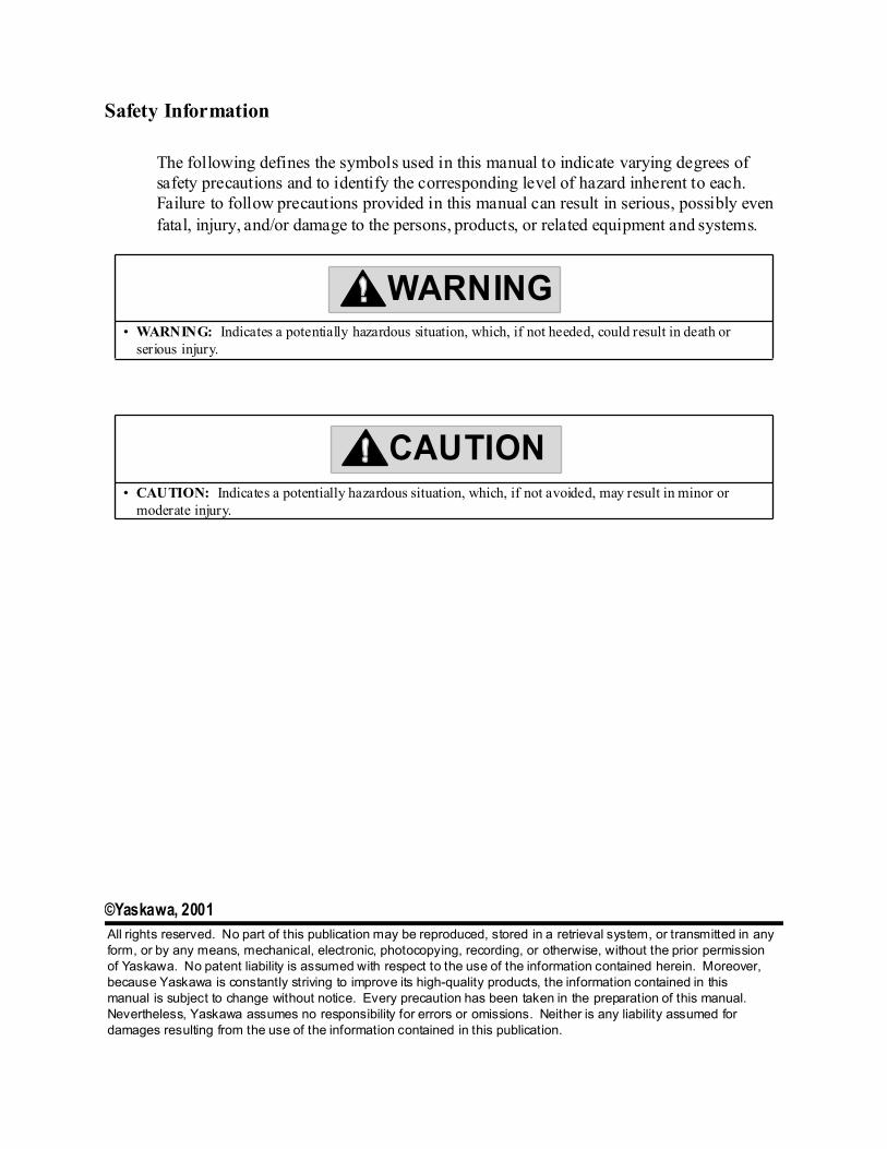
The following defines the symbols used in this manual to indicate varying degrees of safety precautions and to identify the corresponding level of hazard inherent to each. Failure to follow precautions provided in this manual can result in serious, possibly even fatal, injury, and/or damage to the persons, products, or related equipment and systems.
• WARNING: Indicates a potentially hazardous situation, which, if not heeded, could result in death or serious injury.
• CAUTION: Indicates a potentially hazardous situation, which, if not avoided, may result in minor or moderate injury.
WARNING
CAUTION
©Yaskawa, 2001All rights reserved. No part of this publication may be reproduced, stored in a retrieval system, or transmitted in anyform, or by any means, mechanical, electronic, photocopying, recording, or otherwise, without the prior permission of Yaskawa. No patent liability is assumed with respect to the use of the information contained herein. Moreover,because Yaskawa is constantly striving to improve its high-quality products, the information contained in this manual is subject to change without notice. Every precaution has been taken in the preparation of this manual. Nevertheless, Yaskawa assumes no responsibility for errors or omissions. Neither is any liability assumed for damages resulting from the use of the information contained in this publication.

iv
This page intentionally left blank.
Sigma II User’s Manual Table of Contents/Preface
v
1. Checking Product and Part Names . . . . . . . . . . . . . . . . . . . . . . . . . . . . . . . . . . . . . . . . . . 1 - 11.1 Checking the Sigma II Series Products on Delivery . . . . . . . . . . . . . . . . . . . . . . . . . 1 - 2
1.1.1 Servomotors . . . . . . . . . . . . . . . . . . . . . . . . . . . . . . . . . . . . . . . . . . . . . . . . . . . 1 - 21.1.2 Servo Amplifiers . . . . . . . . . . . . . . . . . . . . . . . . . . . . . . . . . . . . . . . . . . . . . . . . 1 - 4
1.2 Product Part Names . . . . . . . . . . . . . . . . . . . . . . . . . . . . . . . . . . . . . . . . . . . . . . . . . . 1 - 51.2.1 Servomotors . . . . . . . . . . . . . . . . . . . . . . . . . . . . . . . . . . . . . . . . . . . . . . . . . . . 1 - 51.2.2 Servo Amplifiers . . . . . . . . . . . . . . . . . . . . . . . . . . . . . . . . . . . . . . . . . . . . . . . . 1 - 6
2. Installation . . . . . . . . . . . . . . . . . . . . . . . . . . . . . . . . . . . . . . . . . . . . . . . . . . . . . . . . . . . . . . 2 - 12.1 Servomotors . . . . . . . . . . . . . . . . . . . . . . . . . . . . . . . . . . . . . . . . . . . . . . . . . . . . . . . . 2 - 2
2.1.1 Storage Temperature . . . . . . . . . . . . . . . . . . . . . . . . . . . . . . . . . . . . . . . . . . . . . 2 - 22.1.2 Installation Site . . . . . . . . . . . . . . . . . . . . . . . . . . . . . . . . . . . . . . . . . . . . . . . . . 2 - 22.1.3 Alignment . . . . . . . . . . . . . . . . . . . . . . . . . . . . . . . . . . . . . . . . . . . . . . . . . . . . . 2 - 32.1.4 Orientation . . . . . . . . . . . . . . . . . . . . . . . . . . . . . . . . . . . . . . . . . . . . . . . . . . . . 2 - 32.1.5 Allowable Shaft Loads . . . . . . . . . . . . . . . . . . . . . . . . . . . . . . . . . . . . . . . . . . . 2 - 42.1.6 Handling Oil and Water . . . . . . . . . . . . . . . . . . . . . . . . . . . . . . . . . . . . . . . . . . 2 - 52.1.7 Cable Stress. . . . . . . . . . . . . . . . . . . . . . . . . . . . . . . . . . . . . . . . . . . . . . . . . . . . 2 - 5
2.2 Servo Amplifiers . . . . . . . . . . . . . . . . . . . . . . . . . . . . . . . . . . . . . . . . . . . . . . . . . . . . 2 - 62.2.1 Storage Conditions . . . . . . . . . . . . . . . . . . . . . . . . . . . . . . . . . . . . . . . . . . . . . . 2 - 62.2.2 Installation Site . . . . . . . . . . . . . . . . . . . . . . . . . . . . . . . . . . . . . . . . . . . . . . . . . 2 - 62.2.3 Orientation . . . . . . . . . . . . . . . . . . . . . . . . . . . . . . . . . . . . . . . . . . . . . . . . . . . . 2 - 72.2.4 Installation . . . . . . . . . . . . . . . . . . . . . . . . . . . . . . . . . . . . . . . . . . . . . . . . . . . . 2 - 8
3. Wiring . . . . . . . . . . . . . . . . . . . . . . . . . . . . . . . . . . . . . . . . . . . . . . . . . . . . . . . . . . . . . . . . . 3 - 13.1 Connecting to Peripheral Devices . . . . . . . . . . . . . . . . . . . . . . . . . . . . . . . . . . . . . . . 3 - 3
3.1.1 Single-Phase (100V or 200V) Main Circuit Specifications . . . . . . . . . . . . . . . 3 - 43.1.2 Three-Phase (200V) Main Circuit Specifications . . . . . . . . . . . . . . . . . . . . . . . 3 - 53.1.3 Three-Phase (400V) Main Circuit Specifications . . . . . . . . . . . . . . . . . . . . . . . 3 - 6
3.2 Servo Amplifier Internal Block Diagrams. . . . . . . . . . . . . . . . . . . . . . . . . . . . . . . . . 3 - 73.2.1 30W to 400W (200V) and 30W to 200W (100V) Models . . . . . . . . . . . . . . . 3 - 73.2.2 0.5kW to 1.5kW (200V) Models . . . . . . . . . . . . . . . . . . . . . . . . . . . . . . . . . . . 3 - 83.2.3 2.0 kW and 5.0kW (200V) Models . . . . . . . . . . . . . . . . . . . . . . . . . . . . . . . . . 3 - 83.2.4 6.0kW to 15.0kW (200V) Models . . . . . . . . . . . . . . . . . . . . . . . . . . . . . . . . . . 3 - 93.2.5 0.5kW to 3.0kW, 400V Models . . . . . . . . . . . . . . . . . . . . . . . . . . . . . . . . . . . . 3 - 93.2.6 5.0kW (400V) Models . . . . . . . . . . . . . . . . . . . . . . . . . . . . . . . . . . . . . . . . . . 3 - 103.2.7 6.0kW to 7.5kW, 400V Models . . . . . . . . . . . . . . . . . . . . . . . . . . . . . . . . . . . 3 - 103.2.8 11.0kW to 15.0kW (400V) Models . . . . . . . . . . . . . . . . . . . . . . . . . . . . . . . . 3 - 113.2.9 22.0kW to 55kW (400V) Models . . . . . . . . . . . . . . . . . . . . . . . . . . . . . . . . . . 3 - 11
3.3 Main Circuit Wiring. . . . . . . . . . . . . . . . . . . . . . . . . . . . . . . . . . . . . . . . . . . . . . . . . 3 - 123.3.1 Names and Descriptions of Main Circuit Terminal . . . . . . . . . . . . . . . . . . . . 3 - 133.3.2 Typical Main Circuit Wiring Example . . . . . . . . . . . . . . . . . . . . . . . . . . . . . . 3 - 143.3.3 Cable Specifications and Peripheral Devices . . . . . . . . . . . . . . . . . . . . . . . . . 3 - 143.3.4 Servo Amplifier Power Losses . . . . . . . . . . . . . . . . . . . . . . . . . . . . . . . . . . . . 3 - 153.3.5 Wiring Main Circuit Terminal Blocks . . . . . . . . . . . . . . . . . . . . . . . . . . . . . . 3 - 16
3.4 I/O Signals . . . . . . . . . . . . . . . . . . . . . . . . . . . . . . . . . . . . . . . . . . . . . . . . . . . . . . . . 3 - 173.4.1 Example of Typical I/O Signal Connections . . . . . . . . . . . . . . . . . . . . . . . . . 3 - 173.4.2 List of CN1 Terminals . . . . . . . . . . . . . . . . . . . . . . . . . . . . . . . . . . . . . . . . . . 3 - 183.4.3 I/O Signal Names and Functions . . . . . . . . . . . . . . . . . . . . . . . . . . . . . . . . . . 3 - 193.4.4 Interface Circuits. . . . . . . . . . . . . . . . . . . . . . . . . . . . . . . . . . . . . . . . . . . . . . . 3 - 21

Sigma II User’s Manual Table of Contents/Preface
vi
3.5 Wiring Encoders (for SGMGH and SGMSH Motors Only) . . . . . . . . . . . . . . . . . . 3 - 243.5.1 Encoder Connections . . . . . . . . . . . . . . . . . . . . . . . . . . . . . . . . . . . . . . . . . . . 3 - 243.5.2 CN2 Encoder Connector Terminal Layout and Types . . . . . . . . . . . . . . . . . . 3 - 25
3.6 Examples of Standard Connections . . . . . . . . . . . . . . . . . . . . . . . . . . . . . . . . . . . . . 3 - 263.6.1 Single-Phase Power Supply Specifications . . . . . . . . . . . . . . . . . . . . . . . . . . 3 - 263.6.2 Three-Phase Power Supply Specifications (200V). . . . . . . . . . . . . . . . . . . . . 3 - 273.6.3 Three-Phase Power Supply Specifications (400V). . . . . . . . . . . . . . . . . . . . . 3 - 28
Large Capacity (400V) . . . . . . . . . . . . . . . . . . . . . . . . . . . . . . . . . . . . . . . . . . 3 - 293.6.4 Position Control Mode . . . . . . . . . . . . . . . . . . . . . . . . . . . . . . . . . . . . . . . . . . 3 - 313.6.5 Speed Control Mode . . . . . . . . . . . . . . . . . . . . . . . . . . . . . . . . . . . . . . . . . . . . 3 - 323.6.6 Torque Control Mode . . . . . . . . . . . . . . . . . . . . . . . . . . . . . . . . . . . . . . . . . . . 3 - 33
4. Trial Operation . . . . . . . . . . . . . . . . . . . . . . . . . . . . . . . . . . . . . . . . . . . . . . . . . . . . . . . . . . 4 - 14.1 Two-Step Trial Operation . . . . . . . . . . . . . . . . . . . . . . . . . . . . . . . . . . . . . . . . . . . . . 4 - 2
4.1.1 Step 1: Trial Operation for Servomotor without Load . . . . . . . . . . . . . . . . . . . 4 - 34.1.2 Step 2: Trial Operation with the Servomotor Connected to a Load . . . . . . . . . 4 - 9
4.2 Additional Setup Procedures in Trial Operation . . . . . . . . . . . . . . . . . . . . . . . . . . . 4 - 104.2.1 Servomotors with Brakes . . . . . . . . . . . . . . . . . . . . . . . . . . . . . . . . . . . . . . . . 4 - 104.2.2 Position Control by Host Controller . . . . . . . . . . . . . . . . . . . . . . . . . . . . . . . 4 - 11
4.3 Minimum Parameters and Input Signals . . . . . . . . . . . . . . . . . . . . . . . . . . . . . . . . . 4 - 124.3.1 Parameters . . . . . . . . . . . . . . . . . . . . . . . . . . . . . . . . . . . . . . . . . . . . . . . . . . . . 4 - 124.3.2 Input Signals . . . . . . . . . . . . . . . . . . . . . . . . . . . . . . . . . . . . . . . . . . . . . . . . . . 4 - 12
5. Parameter Settings and Functions . . . . . . . . . . . . . . . . . . . . . . . . . . . . . . . . . . . . . . . . . . 5 - 15.1 Settings According to Device Characteristics . . . . . . . . . . . . . . . . . . . . . . . . . . . . . . 5 - 4
5.1.1 Switching Servomotor Rotation Direction . . . . . . . . . . . . . . . . . . . . . . . . . . . . 5 - 45.1.2 Setting the Overtravel Limit Function . . . . . . . . . . . . . . . . . . . . . . . . . . . . . . . 5 - 55.1.3 Limiting Torque . . . . . . . . . . . . . . . . . . . . . . . . . . . . . . . . . . . . . . . . . . . . . . . . 5 - 8
5.2 Settings According to Host Controller. . . . . . . . . . . . . . . . . . . . . . . . . . . . . . . . . . . 5 - 135.2.1 Speed Reference . . . . . . . . . . . . . . . . . . . . . . . . . . . . . . . . . . . . . . . . . . . . . . . 5 - 135.2.2 Position Reference . . . . . . . . . . . . . . . . . . . . . . . . . . . . . . . . . . . . . . . . . . . . . 5 - 155.2.3 Using the Encoder Signal Output . . . . . . . . . . . . . . . . . . . . . . . . . . . . . . . . . . 5 - 215.2.4 Sequence I/O Signals . . . . . . . . . . . . . . . . . . . . . . . . . . . . . . . . . . . . . . . . . . . 5 - 255.2.5 Using the Electronic Gear Function . . . . . . . . . . . . . . . . . . . . . . . . . . . . . . . . 5 - 275.2.6 Contact Input Speed Control. . . . . . . . . . . . . . . . . . . . . . . . . . . . . . . . . . . . . . 5 - 325.2.7 Using Torque Control . . . . . . . . . . . . . . . . . . . . . . . . . . . . . . . . . . . . . . . . . . . 5 - 375.2.8 Torque Feed-Forward Function . . . . . . . . . . . . . . . . . . . . . . . . . . . . . . . . . . . 5 - 445.2.9 Speed Feed-Forward Function . . . . . . . . . . . . . . . . . . . . . . . . . . . . . . . . . . . . 5 - 465.2.10 Torque Limiting by Analog Voltage Reference . . . . . . . . . . . . . . . . . . . . . . 5 - 485.2.11 Reference Pulse Inhibit Function (/INHIBIT) . . . . . . . . . . . . . . . . . . . . . . . 5 - 50
5.3 Setting Up the Servo Amplifier . . . . . . . . . . . . . . . . . . . . . . . . . . . . . . . . . . . . . . . . 5 - 515.3.1 Parameters . . . . . . . . . . . . . . . . . . . . . . . . . . . . . . . . . . . . . . . . . . . . . . . . . . . . 5 - 515.3.2 JOG Speed . . . . . . . . . . . . . . . . . . . . . . . . . . . . . . . . . . . . . . . . . . . . . . . . . . . 5 - 525.3.3 Input Circuit Signal Allocation. . . . . . . . . . . . . . . . . . . . . . . . . . . . . . . . . . . . 5 - 535.3.4 Output Circuit Signal Allocation . . . . . . . . . . . . . . . . . . . . . . . . . . . . . . . . . . 5 - 575.3.5 Control Mode Selection . . . . . . . . . . . . . . . . . . . . . . . . . . . . . . . . . . . . . . . . . 5 - 60
5.4 Setting Stop Functions . . . . . . . . . . . . . . . . . . . . . . . . . . . . . . . . . . . . . . . . . . . . . . . 5 - 635.4.1 Adjusting Offset . . . . . . . . . . . . . . . . . . . . . . . . . . . . . . . . . . . . . . . . . . . . . . . 5 - 63
Sigma II User’s Manual Table of Contents/Preface
vii
5.4.2 Servo OFF Stop Mode Selection . . . . . . . . . . . . . . . . . . . . . . . . . . . . . . . . . 5 - 645.4.3 Using the Zero Clamp Function . . . . . . . . . . . . . . . . . . . . . . . . . . . . . . . . . . . 5 - 655.4.4 Using the Holding Brake . . . . . . . . . . . . . . . . . . . . . . . . . . . . . . . . . . . . . . . . 5 - 67
5.5 Forming a Protective Sequence . . . . . . . . . . . . . . . . . . . . . . . . . . . . . . . . . . . . . . . . 5 - 715.5.1 Using Servo Alarm and Alarm Code Outputs . . . . . . . . . . . . . . . . . . . . . . . . 5 - 715.5.2 Using the Servo ON Input Signal (/S-ON) . . . . . . . . . . . . . . . . . . . . . . . . . . . 5 - 735.5.3 Using the Positioning Completed Output Signal (/COIN) . . . . . . . . . . . . . . . 5 - 755.5.4 Speed Coincidence Output (/V-CMP) . . . . . . . . . . . . . . . . . . . . . . . . . . . . . . 5 - 775.5.5 Using the Running Output Signal (/TGON) . . . . . . . . . . . . . . . . . . . . . . . . . . 5 - 795.5.6 Using the Servo Ready Output Signal (/S-RDY) . . . . . . . . . . . . . . . . . . . . . . 5 - 815.5.7 Using the Warning Output Signal (/WARN). . . . . . . . . . . . . . . . . . . . . . . . . 5 - 825.5.8 Using the Near Output Signal (/NEAR) . . . . . . . . . . . . . . . . . . . . . . . . . . . . . 5 - 845.5.9 Handling Power Loss . . . . . . . . . . . . . . . . . . . . . . . . . . . . . . . . . . . . . . . . . . . 5 - 86
5.6 Selecting a Regenerative Resistor . . . . . . . . . . . . . . . . . . . . . . . . . . . . . . . . . . . . . . 5 - 875.6.1 External Regenerative Resistor. . . . . . . . . . . . . . . . . . . . . . . . . . . . . . . . . . . . 5 - 885.6.2 Calculating the Regenerative Power Capacity . . . . . . . . . . . . . . . . . . . . . . . . 5 - 91
5.7 Absolute Encoders . . . . . . . . . . . . . . . . . . . . . . . . . . . . . . . . . . . . . . . . . . . . . . . . . 5 - 1015.7.1 Interface Circuit . . . . . . . . . . . . . . . . . . . . . . . . . . . . . . . . . . . . . . . . . . . . . . 5 - 1025.7.2 Configuring an Absolute Encoder . . . . . . . . . . . . . . . . . . . . . . . . . . . . . . . . 5 - 1035.7.3 Handling Batteries . . . . . . . . . . . . . . . . . . . . . . . . . . . . . . . . . . . . . . . . . . . . 5 - 1055.7.4 Absolute Encoder Setup . . . . . . . . . . . . . . . . . . . . . . . . . . . . . . . . . . . . . . . . 5 - 1065.7.5 Absolute Encoder Reception Sequence . . . . . . . . . . . . . . . . . . . . . . . . . . . . 5 - 110
5.8 Special Wiring . . . . . . . . . . . . . . . . . . . . . . . . . . . . . . . . . . . . . . . . . . . . . . . . . . . . 5 - 1155.8.1 Wiring Precautions . . . . . . . . . . . . . . . . . . . . . . . . . . . . . . . . . . . . . . . . . . . . 5 - 1155.8.2 Wiring for Noise Control . . . . . . . . . . . . . . . . . . . . . . . . . . . . . . . . . . . . . . . 5 - 1225.8.3 Using More Than One Servodrive . . . . . . . . . . . . . . . . . . . . . . . . . . . . . . . . 5 - 1265.8.4 Extending Encoder Cables . . . . . . . . . . . . . . . . . . . . . . . . . . . . . . . . . . . . . . 5 - 1275.8.5 400V Power Supply Voltage . . . . . . . . . . . . . . . . . . . . . . . . . . . . . . . . . . . . 5 - 1295.8.6 Reactor for Harmonic Suppression. . . . . . . . . . . . . . . . . . . . . . . . . . . . . . . . 5 - 1315.8.7 DB Unit . . . . . . . . . . . . . . . . . . . . . . . . . . . . . . . . . . . . . . . . . . . . . . . . . . . . . 5 - 133
5.9 Reserved Parameters . . . . . . . . . . . . . . . . . . . . . . . . . . . . . . . . . . . . . . . . . . . . . . . 5 - 1366. Servo Adjustment . . . . . . . . . . . . . . . . . . . . . . . . . . . . . . . . . . . . . . . . . . . . . . . . . . . . . . . . 6 - 1
6.1 Smooth Operation . . . . . . . . . . . . . . . . . . . . . . . . . . . . . . . . . . . . . . . . . . . . . . . . . . . 6 - 26.1.1 Using the Soft Start Function . . . . . . . . . . . . . . . . . . . . . . . . . . . . . . . . . . . . . . 6 - 26.1.2 Smoothing . . . . . . . . . . . . . . . . . . . . . . . . . . . . . . . . . . . . . . . . . . . . . . . . . . . . . 6 - 36.1.3 Adjusting Gain . . . . . . . . . . . . . . . . . . . . . . . . . . . . . . . . . . . . . . . . . . . . . . . . . 6 - 56.1.4 Adjusting Offset . . . . . . . . . . . . . . . . . . . . . . . . . . . . . . . . . . . . . . . . . . . . . . . . 6 - 66.1.5 Setting the Torque Reference Filter Time Constant . . . . . . . . . . . . . . . . . . . . . 6 - 76.1.6 Notch Filter . . . . . . . . . . . . . . . . . . . . . . . . . . . . . . . . . . . . . . . . . . . . . . . . . . . . 6 - 8
6.2 High-Speed Positioning . . . . . . . . . . . . . . . . . . . . . . . . . . . . . . . . . . . . . . . . . . . . . . . 6 - 96.2.1 Setting Servo Gain . . . . . . . . . . . . . . . . . . . . . . . . . . . . . . . . . . . . . . . . . . . . . . 6 - 96.2.2 Using Feed-Forward Control . . . . . . . . . . . . . . . . . . . . . . . . . . . . . . . . . . . . . 6 - 116.2.3 Using Proportional Control. . . . . . . . . . . . . . . . . . . . . . . . . . . . . . . . . . . . . . . 6 - 126.2.4 Setting Speed Bias . . . . . . . . . . . . . . . . . . . . . . . . . . . . . . . . . . . . . . . . . . . . . 6 - 136.2.5 Using Mode Switch . . . . . . . . . . . . . . . . . . . . . . . . . . . . . . . . . . . . . . . . . . . . 6 - 146.2.6 Speed Feedback Compensation . . . . . . . . . . . . . . . . . . . . . . . . . . . . . . . . . . . 6 - 18
Sigma II User’s Manual Table of Contents/Preface
viii
6.3 Auto-Tuning. . . . . . . . . . . . . . . . . . . . . . . . . . . . . . . . . . . . . . . . . . . . . . . . . . . . . . . 6 - 206.3.1 Online Auto-Tuning . . . . . . . . . . . . . . . . . . . . . . . . . . . . . . . . . . . . . . . . . . . . 6 - 216.3.2 Mechanical Rigidity Settings for Online Auto-Tuning . . . . . . . . . . . . . . . . . 6 - 236.3.3 Saving Results of Online Auto-Tuning . . . . . . . . . . . . . . . . . . . . . . . . . . . . . 6 - 256.3.4 Parameters Related to Online Auto-Tuning . . . . . . . . . . . . . . . . . . . . . . . . . . 6 - 28
6.4 Servo Gain Adjustments . . . . . . . . . . . . . . . . . . . . . . . . . . . . . . . . . . . . . . . . . . . . . 6 - 306.4.1 Servo Gain Parameters . . . . . . . . . . . . . . . . . . . . . . . . . . . . . . . . . . . . . . . . . . 6 - 306.4.2 Basic Rules of Gain Adjustment. . . . . . . . . . . . . . . . . . . . . . . . . . . . . . . . . . . 6 - 316.4.3 Making Manual Adjustments . . . . . . . . . . . . . . . . . . . . . . . . . . . . . . . . . . . . . 6 - 336.4.4 Gain Setting Reference Values . . . . . . . . . . . . . . . . . . . . . . . . . . . . . . . . . . . . 6 - 38
6.5 Analog Monitor . . . . . . . . . . . . . . . . . . . . . . . . . . . . . . . . . . . . . . . . . . . . . . . . . . . . 6 - 407. Using the Digital Operator . . . . . . . . . . . . . . . . . . . . . . . . . . . . . . . . . . . . . . . . . . . . . . . . . 7 - 1
7.1 Basic Operation . . . . . . . . . . . . . . . . . . . . . . . . . . . . . . . . . . . . . . . . . . . . . . . . . . . . . 7 - 27.1.1 Connecting the Digital Operator. . . . . . . . . . . . . . . . . . . . . . . . . . . . . . . . . . . . 7 - 27.1.2 Functions . . . . . . . . . . . . . . . . . . . . . . . . . . . . . . . . . . . . . . . . . . . . . . . . . . . . . . 7 - 37.1.3 Resetting Servo Alarms . . . . . . . . . . . . . . . . . . . . . . . . . . . . . . . . . . . . . . . . . . 7 - 57.1.4 Basic Mode Selection . . . . . . . . . . . . . . . . . . . . . . . . . . . . . . . . . . . . . . . . . . . . 7 - 67.1.5 Status Display Mode . . . . . . . . . . . . . . . . . . . . . . . . . . . . . . . . . . . . . . . . . . . . . 7 - 77.1.6 Operation in Parameter Setting Mode . . . . . . . . . . . . . . . . . . . . . . . . . . . . . . 7 - 107.1.7 Operation in Monitor Mode . . . . . . . . . . . . . . . . . . . . . . . . . . . . . . . . . . . . . . 7 - 18
7.2 Applied Operation . . . . . . . . . . . . . . . . . . . . . . . . . . . . . . . . . . . . . . . . . . . . . . . . . . 7 - 247.2.1 Operation in Alarm Traceback Mode . . . . . . . . . . . . . . . . . . . . . . . . . . . . . . . 7 - 257.2.2 JOG Operation Using the Digital Operator . . . . . . . . . . . . . . . . . . . . . . . . . . 7 - 277.2.3 Automatic Adjustment of the Speed and Torque Reference Offset . . . . . . . . 7 - 307.2.4 Manual Adjustment of the Speed and Torque Reference Offset . . . . . . . . . . 7 - 337.2.5 Clearing Alarm Traceback Data . . . . . . . . . . . . . . . . . . . . . . . . . . . . . . . . . . . 7 - 387.2.6 Checking the Motor Model . . . . . . . . . . . . . . . . . . . . . . . . . . . . . . . . . . . . . . . 7 - 407.2.7 Checking the Software Version . . . . . . . . . . . . . . . . . . . . . . . . . . . . . . . . . . . 7 - 437.2.8 Origin Search Model . . . . . . . . . . . . . . . . . . . . . . . . . . . . . . . . . . . . . . . . . . . 7 - 447.2.9 Initializing Parameter Settings . . . . . . . . . . . . . . . . . . . . . . . . . . . . . . . . . . . . 7 - 477.2.10 Manual Zero Adjustment and Gain Adjustment ofAnalog Monitor Output . . . . . . . . . . . . . . . . . . . . . . . . . . . . . . . . . . . . . . . . . . . . . . 7 - 497.2.11 Adjusting the Motor Current Detection Offset . . . . . . . . . . . . . . . . . . . . . . . 7 - 547.2.12 Write Protected Setting . . . . . . . . . . . . . . . . . . . . . . . . . . . . . . . . . . . . . . . . . 7 - 587.2.13 Clearing the Option Unit Detection Alarm . . . . . . . . . . . . . . . . . . . . . . . . . . 7 - 60
8. Ratings and Characteristics . . . . . . . . . . . . . . . . . . . . . . . . . . . . . . . . . . . . . . . . . . . . . . . . 8 - 18.1 Servomotors: Ratings, Specifications, and Dimensional Drawings . . . . . . . . . . . . . 8 - 2
8.1.1 SGMAH Servomotors. . . . . . . . . . . . . . . . . . . . . . . . . . . . . . . . . . . . . . . . . . . . 8 - 28.1.2 SGMPH Servomotors . . . . . . . . . . . . . . . . . . . . . . . . . . . . . . . . . . . . . . . . . . . . 8 - 78.1.3 SGMGH Servomotors for 1500rpm . . . . . . . . . . . . . . . . . . . . . . . . . . . . . . . . 8 - 118.1.4 SGMSH Servomotors . . . . . . . . . . . . . . . . . . . . . . . . . . . . . . . . . . . . . . . . . . . 8 - 158.1.5 SGMUH Servomotors. . . . . . . . . . . . . . . . . . . . . . . . . . . . . . . . . . . . . . . . . . . 8 - 198.1.6 SGMBH Servomotors . . . . . . . . . . . . . . . . . . . . . . . . . . . . . . . . . . . . . . . . . . . 8 - 22
8.2 Servo Amplifiers . . . . . . . . . . . . . . . . . . . . . . . . . . . . . . . . . . . . . . . . . . . . . . . . . . . 8 - 28
Sigma II User’s Manual Table of Contents/Preface
ix
8.2.1 Combined Specifications . . . . . . . . . . . . . . . . . . . . . . . . . . . . . . . . . . . . . . . . . . . 8 - 348.2.2 Ratings and Specifications . . . . . . . . . . . . . . . . . . . . . . . . . . . . . . . . . . . . . . . 8 - 438.2.3 Base-Mounted Servo Amplifier Dimensions in inches (mm) . . . . . . . . . . . 8 - 35
9. Inspection, Maintenance, and Troubleshooting . . . . . . . . . . . . . . . . . . . . . . . . . . . . . . . . 9 - 19.1 Servodrive Inspection and Maintenance . . . . . . . . . . . . . . . . . . . . . . . . . . . . . . . . . . 9 - 2
9.1.1 Servomotor Inspection . . . . . . . . . . . . . . . . . . . . . . . . . . . . . . . . . . . . . . . . . . . 9 - 29.1.2 Servo Amplifier Inspection. . . . . . . . . . . . . . . . . . . . . . . . . . . . . . . . . . . . . . . . 9 - 39.1.3 Replacing the Battery for the Absolute Encoder . . . . . . . . . . . . . . . . . . . . . . . 9 - 4
9.2 Troubleshooting . . . . . . . . . . . . . . . . . . . . . . . . . . . . . . . . . . . . . . . . . . . . . . . . . . . . . 9 - 59.2.1 Troubleshooting Problems with Alarm Displays . . . . . . . . . . . . . . . . . . . . . . . 9 - 59.2.2 Troubleshooting Problems with No Alarm Display . . . . . . . . . . . . . . . . . . . . 9 - 399.2.3 Alarm Display Table. . . . . . . . . . . . . . . . . . . . . . . . . . . . . . . . . . . . . . . . . . . . 9 - 419.2.4 Warning Displays . . . . . . . . . . . . . . . . . . . . . . . . . . . . . . . . . . . . . . . . . . . . . . 9 - 43
A. Host Controller Connection Examples . . . . . . . . . . . . . . . . . . . . . . . . . . . . . . . . . . . . . . A - 1A.1 Connecting the GL-series MC20 Motion Module . . . . . . . . . . . . . . . . . . . . . . . . . . A - 2A.2 Connecting the CP-9200SH Servo Controller Module (SVA). . . . . . . . . . . . . . . . . A - 3A.3 Connecting the GL-series B2813 Positioning Module . . . . . . . . . . . . . . . . . . . . . . . A - 4A.4 Connecting OMRON's C500-NC221 Position Control Unit . . . . . . . . . . . . . . . . . . A - 5A.5 Connecting OMRON's C500-NC112 Position Control Unit . . . . . . . . . . . . . . . . . . A - 6A.6 Connecting MITSUBISHI's AD72 Positioning Unit . . . . . . . . . . . . . . . . . . . . . . . . A - 7A.7 Connecting MITSUBISHI's AD75 Positioning Unit . . . . . . . . . . . . . . . . . . . . . . . . A - 8
B. List of Parameters . . . . . . . . . . . . . . . . . . . . . . . . . . . . . . . . . . . . . . . . . . . . . . . . . . . . . . . B - 1B.1 Parameters . . . . . . . . . . . . . . . . . . . . . . . . . . . . . . . . . . . . . . . . . . . . . . . . . . . . . . . . . B - 2B.2 Switches . . . . . . . . . . . . . . . . . . . . . . . . . . . . . . . . . . . . . . . . . . . . . . . . . . . . . . . . . . B - 5B.3 Input Signal Selections . . . . . . . . . . . . . . . . . . . . . . . . . . . . . . . . . . . . . . . . . . . . . . . B - 9B.4 Output Signal Selections . . . . . . . . . . . . . . . . . . . . . . . . . . . . . . . . . . . . . . . . . . . . . B - 11B.5 Auxiliary Functions . . . . . . . . . . . . . . . . . . . . . . . . . . . . . . . . . . . . . . . . . . . . . . . . . B - 12B.6 Monitor Modes . . . . . . . . . . . . . . . . . . . . . . . . . . . . . . . . . . . . . . . . . . . . . . . . . . . . B - 13
C. Examples of Standard Connections . . . . . . . . . . . . . . . . . . . . . . . . . . . . . . . . . . . . . . . . C - 1C.1 Single-Phase Power Supply Specifications . . . . . . . . . . . . . . . . . . . . . . . . . . . . . . . . C - 2C.2 Three-Phase Power Supply Specifications (200V) . . . . . . . . . . . . . . . . . . . . . . . . . . C - 3C.3 Three-Phase Power Supply Specifications (400V) . . . . . . . . . . . . . . . . . . . . . . . . . . C - 4
Large Capacity Power Supply Specifications (400V) . . . . . . . . . . . . . . . . . . . . . . . C - 5C.4 Position Control Mode . . . . . . . . . . . . . . . . . . . . . . . . . . . . . . . . . . . . . . . . . . . . . . . C - 7C.5 Speed Control Mode . . . . . . . . . . . . . . . . . . . . . . . . . . . . . . . . . . . . . . . . . . . . . . . . . C - 8C.6 Torque Control Mode . . . . . . . . . . . . . . . . . . . . . . . . . . . . . . . . . . . . . . . . . . . . . . . . C - 9
Sigma II User’s Manual Table of Contents/Preface
x
Using This ManualIntended AudienceThis manual is intended for the following users.• Those designing Sigma IΙ Series servodrive systems.• Those installing or wiring Sigma IΙ Series servodrives.• Those performing trial operation or adjustments of Sigma IΙ Series servodrives.• Those maintaining or inspecting Sigma IΙ Series servodrives.
Description of Technical TermsIn this manual, the following terms are defined as follows:• Servomotor = Sigma IΙ Series SGMAH/SGMPH/SGMGH/SGMSH servomotor. • Servo Amplifier = Sigma IΙ Series SGDH servo amplifier. • Servodrive = A set including a servomotor and servo amplifier. • Servo System = A servo control system that includes the combination of a
servodrive with a host computer and peripheral devices.
Indication of Inverted Signals In this manual, the names of inverted signals (ones that are valid when low) are written with a forward slash (/) before the signal name, as shown in the following equations:
• /S–ON = S–ON • /P–CON = P–CON
Sigma II User’s Manual Table of Contents/Preface
xi
Safety Precautions The following precautions are for checking products upon delivery, installation, wiring, operation, maintenance and inspections.
Checking Products upon Delivery
Installation
Wiring
• Always use the servomotor and servo amplifier in one of the specified combinations.Not doing so may cause fire or malfunction.
• Never use the products in an environment subject to water, corrosive gases, inflammable gases, or combustibles.Doing so may result in electric shock or fire.
• Connect the ground terminal to a class 3 ground (100Ω or less).Improper grounding may result in electric shock or fire.
• Required for 7.5kW amplifiers: Use of Yaskawa kit Number JZSP-CKT75 for wiring the power input and output terminals, or equivalent UL listed closed-loop ring terminals designed to accept 4 AWG wires.
• Required for 200V, 11kW and 15kW amplifiers: Use of Yaskawa kit number JZSP-CKT75 for wiring the power input and output terminals of the SGDH-1AAE, and JZSP-CKT1E for the SGDH-1EAE, or equivalent UL listed closed-loop ring terminal to accept 4 AWG and 2 AWG wires respectively.
• Required for 400V, 6.0kW and 7.5kW amplifiers: Use of Yaskawa kit Number JZSP-CKT75DE for wiring the power input and output terminals, or equivalent UL listed closed-loop ring terminals designed to accept 8 AWG wires.
• Required for 400V, 11kW amplifiers: Use of Yaskawa kit Number JZSP-CKT1ADE for wiring the power input and output terminals, or equivalent UL listed closed-loop ring terminals designed to accept 8 AWG wires.
• Required for 400V, 15kW amplifiers: Use of Yaskawa kit Number JZSP-CKT1EDE for wiring the power input and output terminals, or equivalent UL listed closed-loop ring terminals designed to accept 6 AWG wires.
CAUTION
CAUTION
WARNING
Sigma II User’s Manual Table of Contents/Preface
xii
Operation
• Do not connect a three-phase power supply to the U, V, or W output terminals.Doing so may result in injury or fire.
• Securely fasten the power supply terminal screws and motor output terminal screws. Not doing so may result in fire.
• Never touch any rotating motor parts while the motor is running.Doing so may result in injury.
• Conduct trial operation on the servomotor alone with the motor shaft disconnected from machine to avoid any unexpected accidents. Not doing so may result in injury.
• Before starting operation with a machine connected, change the settings to match the parameters of the machine. Starting operation without matching the proper settings may cause the machine to run out of control or malfunction.
• Before starting operation with a machine connected, make sure that an emergency stop can be applied at any time. Not doing so may result in injury.
• Do not touch the heat sinks during operation. Not doing so may result in burns due to high temperatures.
CAUTION
CAUTION
CAUTION
Sigma II User’s Manual Table of Contents/Preface
xiii
Maintenance and Inspection
General Precautions
• Do not remove the panel cover while the power is ON.Doing so carries a risk of electric shock.
• Do not touch terminals for five minutes after the power has been turned OFF.Residual voltage may cause electric shock.
• Never touch the inside of the servo amplifier.Doing so may result in electric shock.
• Do not disassemble the servomotor.Doing so may result in electric shock or injury
• Do not attempt to change wiring while the power is ON.Doing so may result in electric shock or injury
• The drawings presented in this manual are sometimes shown without covers or protective guards. Always replace the cover or protective guard as specified first, and then operate the products in accordance with the manual.
• The drawings presented in this manual are typical examples and may not match the product you received. • This manual is subject to change due to product improvement, specification modification, and manual
improvement. When this manual is revised, the manual code is updated and the new manual is published as a next edition. The edition number appears on the front and back covers.
• If the manual must be ordered due to loss or damage, inform your nearest Yaskawa representative or one of the offices listed on the back of this manual.
• Yaskawa will not take responsibility for the results of unauthorized modifications of this product. Yaskawa shall not be liable for any damages or troubles resulting from unauthorized modification.
WARNING
CAUTION
Note the following to ensure safe application:

Sigma II User’s Manual Table of Contents/Preface
xiv
Notes:
Sigma II User’s Manual Chapter 1: Checking Product and Part Names
1 - 1
1 Checking Product and Part Names
This chapter describes the procedure for checking products upon delivery as well as names for product parts.
1.1 Checking the Sigma II Series Products on Delivery............................................ 1-2
1.1.1 Servomotors ................................................................................................ 1-2
1.1.2 Servo Amplifiers ......................................................................................... 1-4
1.2 Product Part Names ............................................................................................. 1-5
1.2.1 Servomotors ................................................................................................ 1-5
1.2.2 Servo Amplifiers ......................................................................................... 1-6
Sigma II User’s Manual Chapter 1: Checking Product and Part Names
1 - 2
1.1 Checking the Sigma II Series Products on DeliveryThe following procedure is suggested to check Sigma II series products upon delivery.Use the following checklist when Sigma II series products are delivered.
If any of the above are faulty or incorrect, contact Yaskawa or an authorized distributor.
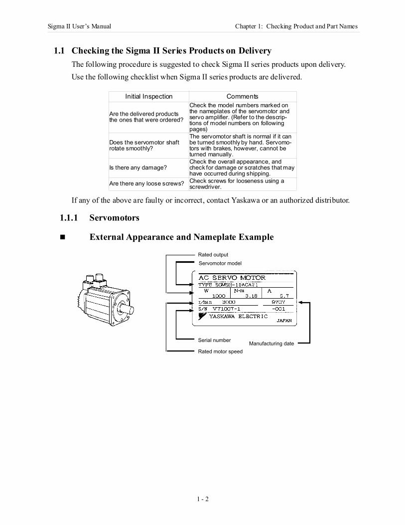
1.1.1 Servomotors
External Appearance and Nameplate Example
Initial Inspection Comments
Are the delivered products the ones that were ordered?
Check the model numbers marked on the nameplates of the servomotor and servo amplifier. (Refer to the descrip-tions of model numbers on following pages)
Does the servomotor shaft rotate smoothly?
The servomotor shaft is normal if it can be turned smoothly by hand. Servomo-tors with brakes, however, cannot be turned manually.
Is there any damage?Check the overall appearance, and check for damage or scratches that may have occurred during shipping.
Are there any loose screws? Check screws for looseness using a screwdriver.
Manufacturing dateRated motor speed
Servomotor modelRated output
Serial number
Sigma II User’s Manual Chapter 1: Checking Product and Part Names
1 - 3
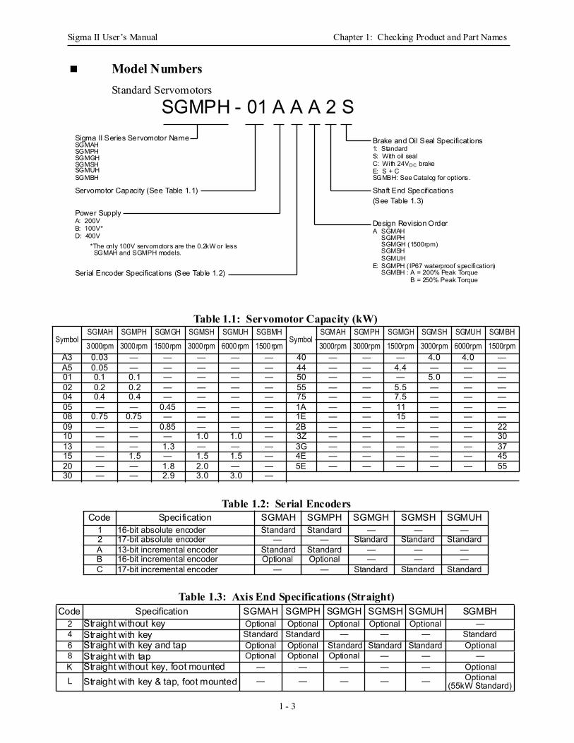
Model Numbers Standard Servomotors
Table 1.1: Servomotor Capacity (kW)
Table 1.2: Serial Encoders
Table 1.3: Axis End Specifications (Straight)
SymbolSGMAH SGMPH SGMGH SGMSH SGMUH SGBMH
SymbolSGMAH SGMPH SGMGH SGMSH SGMUH SGMBH
3000rpm 3000rpm 1500rpm 3000rpm 6000rpm 1500rpm 3000rpm 3000rpm 1500rpm 3000rpm 6000rpm 1500rpmA3 0.03 — — — — — 40 — — — 4.0 4.0 —A5 0.05 — — — — — 44 — — 4.4 — — —01 0.1 0.1 — — — — 50 — — — 5.0 — —02 0.2 0.2 — — — — 55 — — 5.5 — — —04 0.4 0.4 — — — — 75 — — 7.5 — — —05 — — 0.45 — — — 1A — — 11 — — —08 0.75 0.75 — — — — 1E — — 15 — — —09 — — 0.85 — — — 2B — — — — — 2210 — — — 1.0 1.0 — 3Z — — — — — 3013 — — 1.3 — — — 3G — — — — — 3715 — 1.5 — 1.5 1.5 — 4E — — — — — 4520 — — 1.8 2.0 — — 5E — — — — — 5530 — — 2.9 3.0 3.0 —
Code Specification SGMAH SGMPH SGMGH SGMSH SGMUH1 16-bit absolute encoder Standard Standard — — —2 17-bit absolute encoder — — Standard Standard StandardA 13-bit incremental encoder Standard Standard — — —B 16-bit incremental encoder Optional Optional — — —C 17-bit incremental encoder — — Standard Standard Standard
Code Specification SGMAH SGMPH SGMGH SGMSH SGMUH SGMBH2 Straight without key Optional Optional Optional Optional Optional —4 Straight with key Standard Standard — — — Standard6 Straight with key and tap Optional Optional Standard Standard Standard Optional8 Straight with tap Optional Optional Optional — — —K Straight without key, foot mounted — — — — — OptionalL Straight with key & tap, foot mounted — — — — — Optional
(55kW Standard)
SGMPH - 01 A A A 2 SSigma II Series Servomotor NameSGMAHSGMPHSGMGHSGMSH
Servomotor Capacity (See Table 1.1)
A: 200VB: 100V*
*The only 100V servomotors are the 0.2kW or less SGMAH and SGMPH models.
Serial Encoder Specificat ions (See Table 1.2)
Brake and Oil Seal Specificat ions1: StandardS: With oil sealC: With 24VDC brakeE: S + C
Shaft End Specif ications(See Table 1.3)
Design Revision OrderA SGMAH
SGMPHSGMGH (1500rpm)SGMSH
SGMPH (IP67 waterproof specification)E:
D: 400V
SGMUH
SGMUH
Power Supply
SGMBH SGMBH: See Catalog for options.
SGMBH : A = 200% Peak Torque B = 250% Peak Torque
Sigma II User’s Manual Chapter 1: Checking Product and Part Names
1 - 4
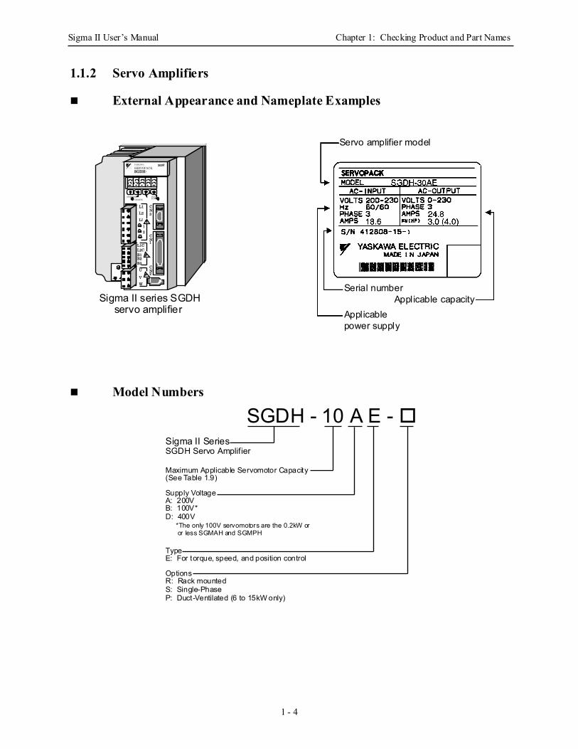
1.1.2 Servo Amplifiers
External Appearance and Nameplate Examples
Model Numbers
L1L2L3
U
VW
L1CL2CB1B2B3
12
CN3
CN1
CN2
YASKAWA
SERVOPACK
MODE/SET DATA/CHARGE POWER
SGDH-200V
Sigma II series SGDHservo amplifier
Servo amplifier model
Serial number
Applicable power supply
Applicable capacity
SGDH - 10 A E - Sigma II SeriesSGDH Servo Amplifier
Maximum Applicable Servomotor Capacity(See Table 1.9)
Supply VoltageA: 200VB: 100V*
TypeE: For torque, speed, and position control
OptionsR: Rack mounted
*The only 100V servomotors are the 0.2kW or or less SGMAH and SGMPH
S: Single-Phase
D: 400V
P: Duct-Ventilated (6 to 15kW only)
Sigma II User’s Manual Chapter 1: Checking Product and Part Names
1 - 5
Table 1.4: Maximum Applicable Servomotor Capacity
1.2 Product Part NamesThis section describes product part names.
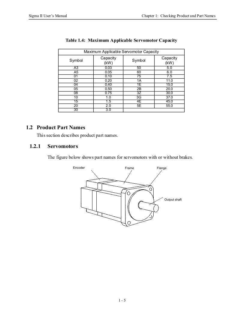
1.2.1 Servomotors
The figure below shows part names for servomotors with or without brakes.
Maximum Applicable Servomotor Capacity
Symbol Capacity(kW) Symbol Capacity
(kW)A3 0.03 50 5.0A5 0.05 60 6.001 0.10 75 7.502 0.20 1A 11.004 0.40 1E 15.005 0.50 2B 20.008 0.75 3Z 30.010 1.0 3G 37.015 1.5 4E 45.020 2.0 5E 55.030 3.0
Encoder Frame Flange
Output shaft
Sigma II User’s Manual Chapter 1: Checking Product and Part Names
1 - 6
1.2.2 Servo Amplifiers
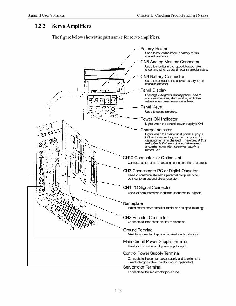
The figure below shows the part names for servo amplifiers.
Battery Holder
CN5 Analog Monitor Connector
CN8 Battery Connector
Panel Display
Panel Keys
Power ON Indicator
Charge Indicator
CN10 Connector for Option Unit
CN3 Connector to PC or Digital Operator
CN1 I/O Signal Connector
Nameplate
CN2 Encoder Connector
Ground Terminal
Main Circuit Power Supply Terminal
Control Power Supply Terminal
Servomotor Terminal
Used to house the backup battery for anabsolute encoder.
Used to monitor motor speed, torque refer-ence, and other values through a special cable.
Used to connect to the backup battery for anabsolute encoder.
Five-digit 7-segment display panel used to show servo status, alarm status, and othervalues when parameters are entered.
Used to set parameters.
Lights when the control power supply is ON.
Lights when the main circuit power supply isON and stays as long as that component’scapacitor remains charged. Therefore, if this indicator is ON, do not touch the servo amplifier, even after the power supply isturned OFF.
Connects option units for expanding the amplifier’s functions.
Used to communicate with a personal computer or to connect to an optional digital operator.
Used for both reference input and sequence I/O signals.
Indicates the servo amplifier model and its specific ratings.
Connects to the encoder in the servomotor.
Must be connected to protect against electrical shock.
Used for the main circuit power supply input.
Connects to the control power supply and to externallymounted regenerative resistor (where applicable).
Connects to the servomotor power line.
Sigma II User’s Manual Chapter 2: Installation
2 - 1
2 Installation
This chapter describes precautions for Sigma II Series servomotor and servo amplifier installation.
2.1 Servomotors ......................................................................................................... 2-2
2.1.1 Storage Temperature ................................................................................... 2-2
2.1.2 Installation Site ........................................................................................... 2-2
2.1.3 Alignment ................................................................................................... 2-3
2.1.4 Orientation .................................................................................................. 2-3
2.1.5 Allowable Shaft Loads................................................................................ 2-4
2.1.8 Handling Oil and Water .............................................................................. 2-6
2.1.9 Cable Stress ................................................................................................. 2-6
2.2 Servo Amplifiers .................................................................................................. 2-7
2.2.1 Storage Conditions ...................................................................................... 2-7
2.2.2 Installation Site ........................................................................................... 2-7
2.2.3 Orientation .................................................................................................. 2-8
2.2.4 Installation .................................................................................................. 2-9
Sigma II User’s Manual Chapter 2: Installation
2 - 2
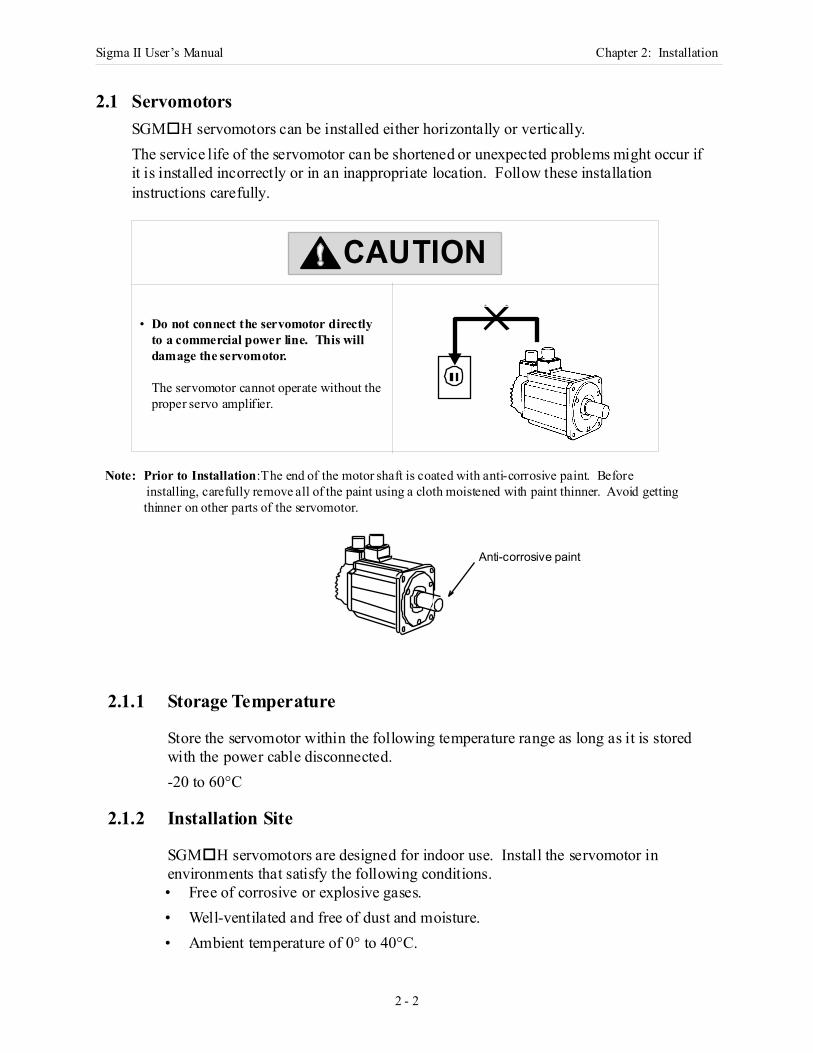
2.1 ServomotorsSGM H servomotors can be installed either horizontally or vertically. The service life of the servomotor can be shortened or unexpected problems might occur if it is installed incorrectly or in an inappropriate location. Follow these installation instructions carefully.
Note: Prior to Installation:The end of the motor shaft is coated with anti-corrosive paint. Before installing, carefully remove all of the paint using a cloth moistened with paint thinner. Avoid getting thinner on other parts of the servomotor.
2.1.1 Storage Temperature
Store the servomotor within the following temperature range as long as it is stored with the power cable disconnected.-20 to 60°C
2.1.2 Installation Site
SGM H servomotors are designed for indoor use. Install the servomotor in environments that satisfy the following conditions.• Free of corrosive or explosive gases.• Well-ventilated and free of dust and moisture.• Ambient temperature of 0° to 40°C.
• Do not connect the servomotor directlyto a commercial power line. This willdamage the servomotor.
The servomotor cannot operate without theproper servo amplifier.
CAUTION
Anti-corrosive paint
Sigma II User’s Manual Chapter 2: Installation
2 - 3
• Relative humidity (r.h.) of 20 to 80% with no condensation.• Accessible for inspection and cleaning.
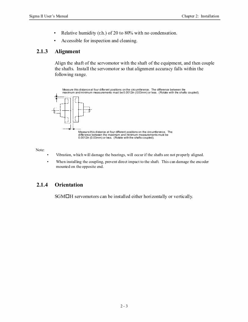
2.1.3 Alignment
Align the shaft of the servomotor with the shaft of the equipment, and then couple the shafts. Install the servomotor so that alignment accuracy falls within the following range.
Note:• Vibration, which will damage the bearings, will occur if the shafts are not properly aligned.
• When installing the coupling, prevent direct impact to the shaft. This can damage the encoder mounted on the opposite end.
2.1.4 Orientation
SGM H servomotors can be installed either horizontally or vertically.
Measure this distance at four different positions on the circumference. The difference between themaximum and minimum measurements must be 0.0012in (0.03mm) or less. (Rotate with the shafts coupled).
Measure this distance at four different positions on the circumference. Thedifference between the maximum and minimum measurements must be 0.0012in (0.03mm) or less. (Rotate with the shafts coupled).
Sigma II User’s Manual Chapter 2: Installation
2 - 4
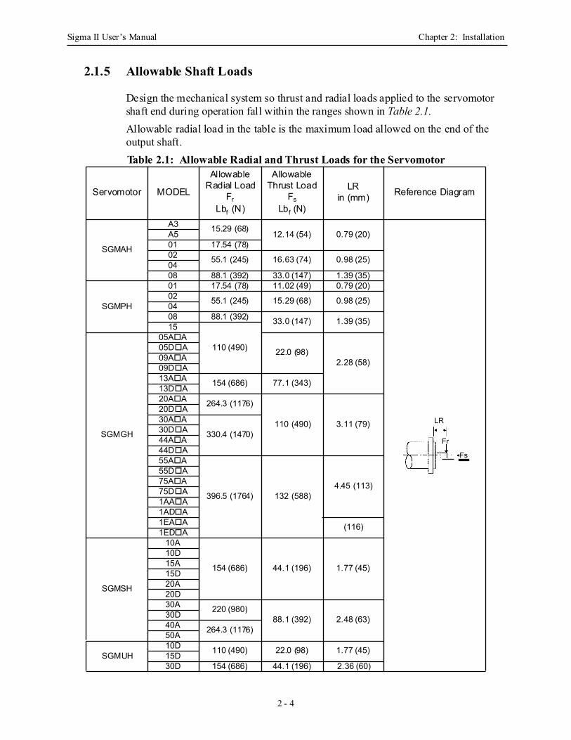
2.1.5 Allowable Shaft Loads
Design the mechanical system so thrust and radial loads applied to the servomotor shaft end during operation fall within the ranges shown in Table 2.1.Allowable radial load in the table is the maximum load allowed on the end of the output shaft.Table 2.1: Allowable Radial and Thrust Loads for the Servomotor
Servomotor MODEL
Allowable Radial Load
Fr Lbf (N)
Allowable Thrust Load
Fs Lbf (N)
LRin (mm) Reference Diagram
SGMAH
A3 15.29 (68) 12.14 (54) 0.79 (20)A501 17.54 (78)02 55.1 (245) 16.63 (74) 0.98 (25)0408 88.1 (392) 33.0 (147) 1.39 (35)
SGMPH
01 17.54 (78) 11.02 (49) 0.79 (20)02 55.1 (245) 15.29 (68) 0.98 (25)0408 88.1 (392) 33.0 (147) 1.39 (35)15
110 (490)
SGMGH
05A A
22.0 (98)2.28 (58)
05D A09A A09D A13A A 154 (686) 77.1 (343)13D A20A A 264.3 (1176)
110 (490) 3.11 (79)
20D A30A A
330.4 (1470)30D A44A A44D A55A A
396.5 (1764) 132 (588)4.45 (113)
55D A75A A75D A1AA A1AD A1EA A (116)1ED A
SGMSH
10A
154 (686) 44.1 (196) 1.77 (45)
10D15A15D20A20D30A 220 (980)
88.1 (392) 2.48 (63)30D40A 264.3 (1176)50A
SGMUH10D 110 (490) 22.0 (98) 1.77 (45)15D30D 154 (686) 44.1 (196) 2.36 (60)
LR
Fr
Fs
Sigma II User’s Manual Chapter 2: Installation
2 - 5
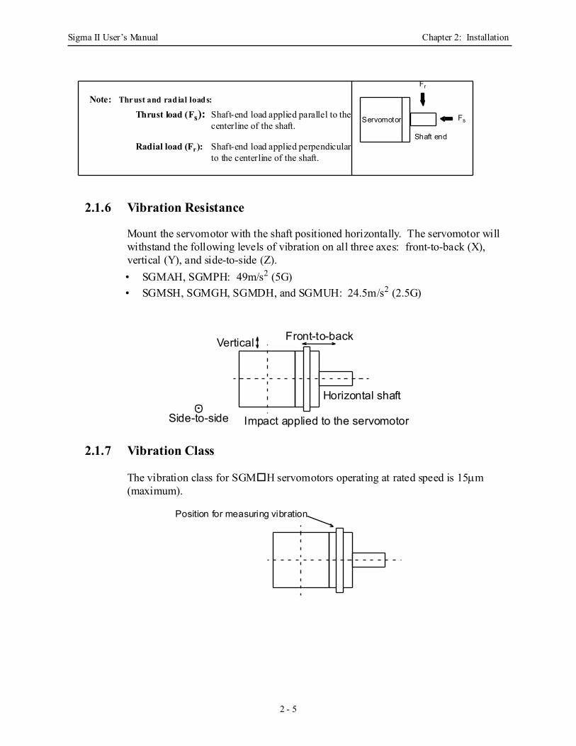
2.1.6 Vibration Resistance
Mount the servomotor with the shaft positioned horizontally. The servomotor will withstand the following levels of vibration on all three axes: front-to-back (X), vertical (Y), and side-to-side (Z).• SGMAH, SGMPH: 49m/s2 (5G)• SGMSH, SGMGH, SGMDH, and SGMUH: 24.5m/s2 (2.5G)
2.1.7 Vibration Class
The vibration class for SGM H servomotors operating at rated speed is 15µm (maximum).
Servomotor
Shaft end
Fr
Fs
Thrust and radial loads:
Thrust load (Fs):
Radial load (Fr):
Note:Shaft-end load applied parallel to thecenterline of the shaft.
Shaft-end load applied perpendicularto the centerline of the shaft.
Vertical
Side-to-side
Front-to-back
Horizontal shaft
Impact applied to the servomotor
Position for measuring vibration
Sigma II User’s Manual Chapter 2: Installation
2 - 6
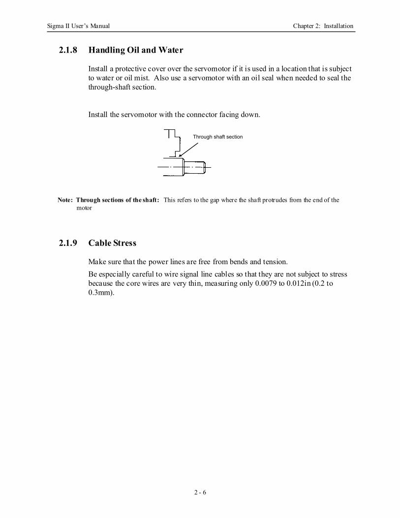
2.1.8 Handling Oil and Water
Install a protective cover over the servomotor if it is used in a location that is subject to water or oil mist. Also use a servomotor with an oil seal when needed to seal the through-shaft section.
Install the servomotor with the connector facing down.
Note: Through sections of the shaft: This refers to the gap where the shaft protrudes from the end of the motor
2.1.9 Cable Stress
Make sure that the power lines are free from bends and tension.Be especially careful to wire signal line cables so that they are not subject to stress because the core wires are very thin, measuring only 0.0079 to 0.012in (0.2 to 0.3mm).
Through shaft section
Sigma II User’s Manual Chapter 2: Installation
2 - 7
2.2 Servo AmplifiersThe SGDH servo amplifiers are base-mounted servoamps. Incorrect installation will cause problems. Follow the installation instructions below.
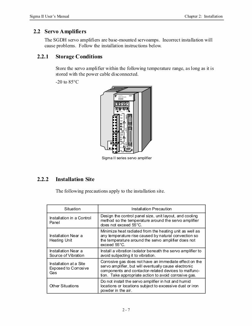
2.2.1 Storage Conditions
Store the servo amplifier within the following temperature range, as long as it is stored with the power cable disconnected.-20 to 85°C
2.2.2 Installation Site
The following precautions apply to the installation site.
Situation Installation Precaution
Installation in a Control Panel
Design the control panel size, unit layout, and cooling method so the temperature around the servo amplifier does not exceed 55°C.
Installation Near a Heating Unit
Minimize heat radiated from the heating unit as well as any temperature rise caused by natural convection so the temperature around the servo amplifier does not exceed 55°C.
Installation Near a Source of Vibration
Install a vibration isolator beneath the servo amplifier to avoid subjecting it to vibration.
Installation at a Site Exposed to Corrosive Gas
Corrosive gas does not have an immediate effect on the servo amplifier, but will eventually cause electronic components and contactor-related devices to malfunc-tion. Take appropriate action to avoid corrosive gas.
Other SituationsDo not install the servo amplifier in hot and humid locations or locations subject to excessive dust or iron powder in the air.
L1
L2
L3
U
V
W
L1CL2CB1B2B3
1
2
CN3
CN1
CN2
YASKAWA
SERVOPACK
MODE/SET DATA/CHARGE POWER
SGDH-
200V
Sigma II series servo amplifier
Sigma II User’s Manual Chapter 2: Installation
2 - 8
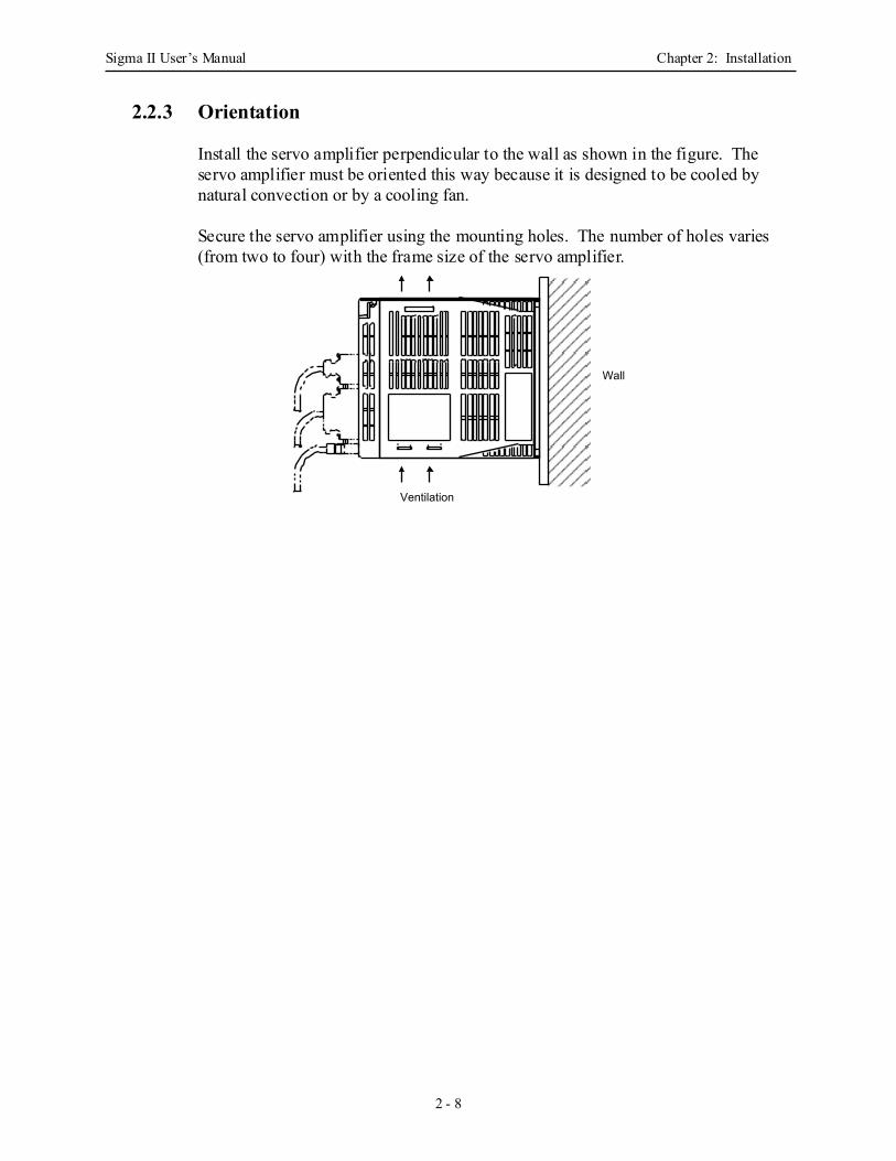
2.2.3 Orientation
Install the servo amplifier perpendicular to the wall as shown in the figure. The servo amplifier must be oriented this way because it is designed to be cooled by natural convection or by a cooling fan.
Secure the servo amplifier using the mounting holes. The number of holes varies (from two to four) with the frame size of the servo amplifier.
Ventilation
Wall
Sigma II User’s Manual Chapter 2: Installation
2 - 9
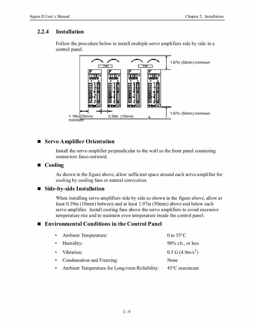
2.2.4 Installation
Follow the procedure below to install multiple servo amplifiers side by side in a control panel.
Servo Amplifier Orientation Install the servo amplifier perpendicular to the wall so the front panel containing connectors faces outward.
Cooling As shown in the figure above, allow sufficient space around each servo amplifier for cooling by cooling fans or natural convection.
Side-by-side InstallationWhen installing servo amplifiers side by side as shown in the figure above, allow at least 0.39in (10mm) between and at least 1.97in (50mm) above and below each servo amplifier. Install cooling fans above the servo amplifiers to avoid excessive temperature rise and to maintain even temperature inside the control panel.
Environmental Conditions in the Control Panel
• Ambient Temperature: 0 to 55°C• Humidity: 90% r.h., or less
• Vibration: 0.5 G (4.9m/s2)• Condensation and Freezing: None• Ambient Temperature for Long-term Reliability: 45°C maximum
1.18in (30mm) 0.39in (10mm)minimum
1.97in (50mm) minimum
1.97in (50mm) minimum
Fan Fan

Sigma II User’s Manual Chapter 2: Installation
2 - 10
NOTES:
Sigma II User’s Manual Chapter 3: Wiring
3 - 1
3 WiringThis chapter describes the procedure used to connect Sigma II Series products to peripheral devices and gives typical exam-ples of main circuit wiring as well as I/O signal connections.
3.1 Connecting to Peripheral Devices........................................................................ 3-3
3.1.1 Single-Phase (100V or 200V) Main Circuit Specifications........................ 3-4
3.1.2 Three-Phase (200V) Main Circuit Specifications ....................................... 3-5
3.1.3 Three-Phase (400V) Main Circuit Specifications ....................................... 3-6
3.2 Servo Amplifier Internal Block Diagrams........................................................... 3-7
3.2.1 30W to 400W (200V) and 30W to 200W (100V) Models ......................... 3-7
3.2.2 0.5kW to 1.5kW (200V) Models ................................................................ 3-8
3.2.3 2.0 kW to 5.0kW (200V) Models ............................................................... 3-8
3.2.4 6.0kW to 15.0kW (200V) Models .............................................................. 3-9
3.2.5 0.5kW to 3.0kW, 400V Models .................................................................. 3-9
3.2.6 5.0kW (400V) Models .............................................................................. 3-10
3.2.7 6.0kW to 7.5kW, 400V Models ................................................................ 3-10
3.2.8 11.0kW to 15.0kW (400V) Models .......................................................... 3-11
3.2.9 22.0kW to 55kW (400V) Models ............................................................. 3-11
3.3 Main Circuit Wiring........................................................................................... 3-12
3.3.1 Names and Descriptions of Main Circuit Terminal .................................. 3-13
3.3.2 Typical Main Circuit Wiring Example...................................................... 3-14
3.3.3 Cable Specifications and Peripheral Devices ........................................... 3-14
3.3.4 Servo Amplifier Power Losses ................................................................. 3-15
3.3.5 Wiring Main Circuit Terminal Blocks ...................................................... 3-16
3.4 I/O Signals ......................................................................................................... 3-17
3.4.1 Example of Typical I/O Signal Connections ............................................ 3-17
3.4.2 List of CN1 Terminals .............................................................................. 3-18
3.4.3 I/O Signal Names and Functions .............................................................. 3-19
3.4.4 Interface Circuits....................................................................................... 3-21
3.5 Wiring Encoders (for SGMGH and SGMSH Motors Only).............................. 3-24
3.5.1 Encoder Connections ................................................................................ 3-24
3.5.2 CN2 Encoder Connector Terminal Layout and Types .............................. 3-25
Sigma II User’s Manual Chapter 3: Wiring
3 - 2
3.6 Examples of Standard Connections ................................................................... 3-26
3.6.1 Single-Phase Power Supply Specifications .............................................. 3-26
3.6.2 Three-Phase Power Supply Specifications (200V)................................... 3-27
3.6.3 Three-Phase Power Supply Specifications (400V)................................... 3-28
Large Capacity, 400V ............................................................................... 3-29
3.6.4 Position Control Mode .............................................................................. 3-31
3.6.5 Speed Control Mode ................................................................................. 3-32
3.6.6 Torque Control Mode................................................................................ 3-33

Sigma II User’s Manual Chapter 3: Wiring
3 - 3
3.1 Connecting to Peripheral DevicesThis section provides examples of standard Sigma II Series product connections to peripheral devices.It also briefly explains how to connect each peripheral device.
Sigma II User’s Manual Chapter 3: Wiring
3 - 4
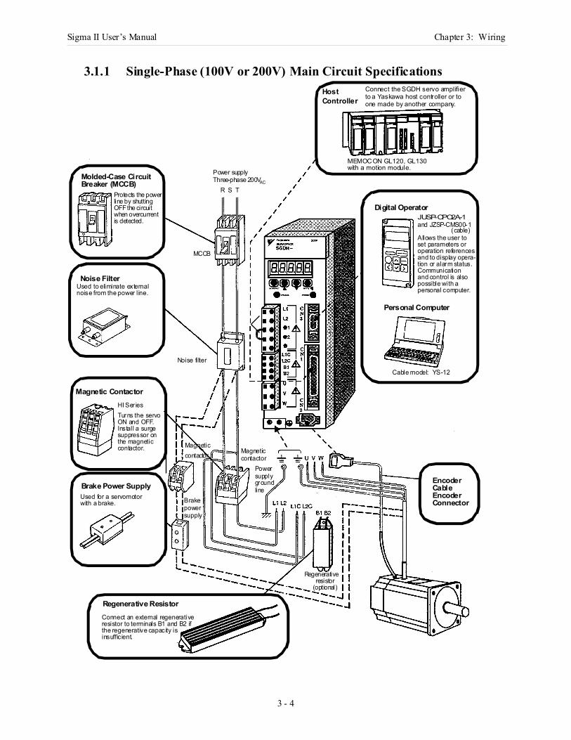
3.1.1 Single-Phase (100V or 200V) Main Circuit SpecificationsHostController
Connect the SGDH servo amplifier to a Yaskawa host controller or toone made by another company.
MEMOCON GL120, GL130with a motion module.
Molded-Case CircuitBreaker (MCCB)
Noise Filter
Magnetic Contactor
Brake Power Supply
Regenerative Resistor
Digital Operator
Personal Computer
EncoderCableEncoderConnector
JUSP-OPO2A-1
Allows the user to set parameters oroperation referencesand to display opera-tion or alarm status.Communicationand control is also possible with apersonal computer.
Cable model: YS-12
Used to eliminate external
Protects the power
Used for a servomotor
Connect an external regenerative
line by shutting OFF the circuitwhen overcurrentis detected.
HI Ser ies
noise from the power line.
Turns the servoON and OFF.Install a surgesuppressor onthe magneticcontactor.
with a brake.
resistor to terminals B1 and B2 ifthe regenerative capacity isinsufficient.
and JZSP-CMS00-1(cable)
Brakepowersupply
MagneticMagneticcontactorcontactor
Powersupplygroundline
Noise filter
Power supplyThree-phase 200VAC
R S T
MCCB
Regenerativeresistor
(optional)
Sigma II User’s Manual Chapter 3: Wiring
3 - 5
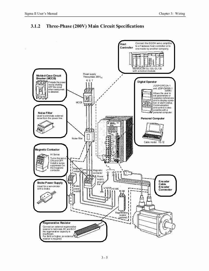
3.1.2 Three-Phase (200V) Main Circuit Specifications
HostController
Connect the SGDH servo amplifier to a Yaskawa host controller or toone made by another company.
MEMOCON GL120, GL130with a motion module.
Molded-Case CircuitBreaker (MCCB)
Noise Filter
Magnetic Contactor
Brake Power Supply
Regenerative Resistor
Digital Operator
Personal Computer
EncoderCableEncoderConnector
JUSP-OPO2A-1
Allows the user to set parameters oroperation referencesand to display opera-tion or alarm status.Communicationand control is also possible with apersonal computer.
Cable model: YS-12
Used to eliminate external
Protects the power
Used for a servomotor
Connect an external regenerative
line by shutting OFF the circuitwhen overcurrentis detected.
HI Series
noise from the power line.
Turns the servoON and OFF.Install a surgesuppressor onthe magneticcontactor.
with a brake.
resistor to terminals B1 and B2 ifthe regenerative capacity isinsufficient.
and JZSP-CMS00-1(cable)
Brakepowersupply
MagneticMagneticcontactor
contactor
Powersupplygroundline
Noise filter
Power supplyThree-phase 200VAC
R S T
MCCB
Regenerativeresistor
(optional)
For 6kW or higher, an externalresistor is required.
Sigma II User’s Manual Chapter 3: Wiring
3 - 6
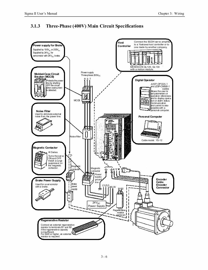
3.1.3 Three-Phase (400V) Main Circuit Specifications
HostController
Connect the SGDH servo amplifier to a Yaskawa host controller or toone made by another company.
MEMOCON GL120, GL130w ith a motion module.
Molded-Case CircuitBreaker (MCCB)
Noise Filter
Magnetic Contactor
Brake Power Supply
Regenerative Resistor
Digital Operator
Personal Computer
EncoderCableEncoderConnector
JUSP-OPO2A-1
Allows the user to set parameters oroperation referencesand to display opera-tion or alarm status.Communicationand control is also possible with apersonal computer.
Cable model: YS-12
Used to eliminate external
Protects the power
Used for a servomotor
Connect an external regenerative
line by shutting OFF the circuitwhen overcurrentis detected.
HI Series
noise from the power line.
Turns the servoON and OFF.Install a surgesuppressor onthe magneticcontactor.
with a brake.
resistor to terminals B1 and B2if the regenerative capacityis insufficient.
and JZSP-CMS00-1(cable)
Brakepowersupply
MagneticMagneticcontactor
contactor
Powersupplygroundline
Noise filter
Power supplyThree-phase 200VAC
R S T
MCCB
Regenerativeresistor
(optional)
L1 L2 L324V 0V
B1 B2
Power supply for BrakeSupplied by 100Vac or 200VacSupplied by 24VDC forservomotor with 24VDC brake.
24VDCPower Supply
For 6kW or higher, an externalresistor is required.
Sigma II User’s Manual Chapter 3: Wiring
3 - 7
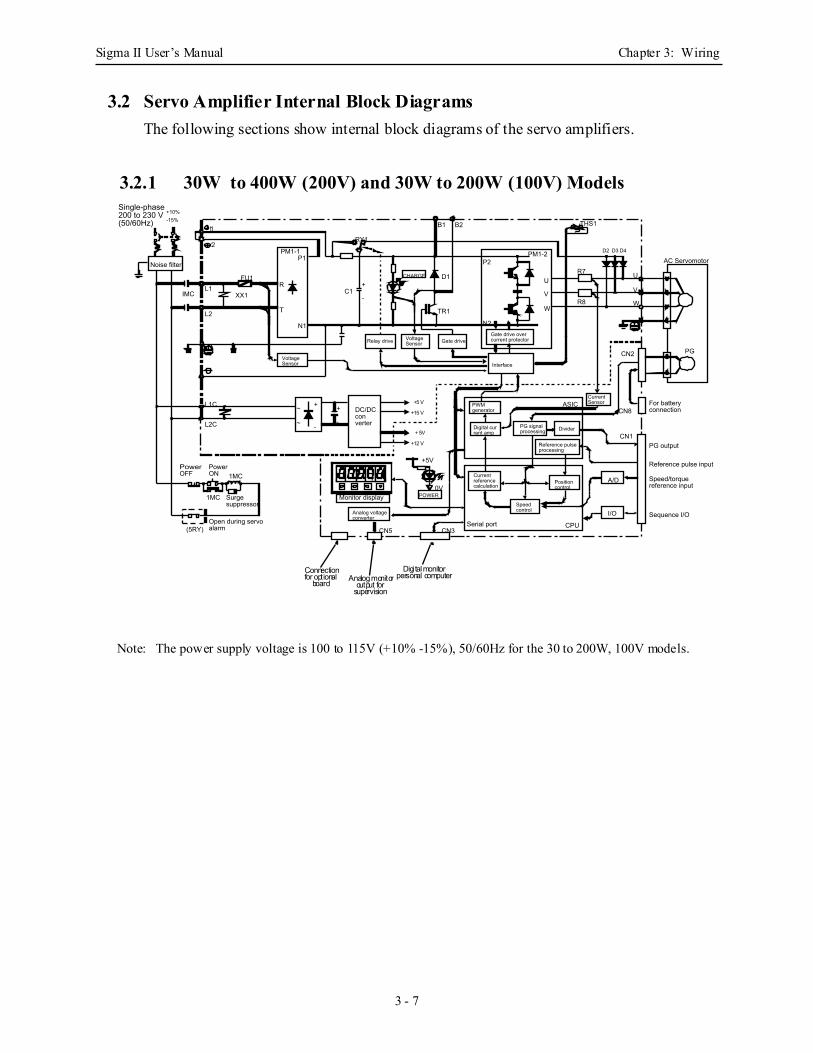
3.2 Servo Amplifier Internal Block DiagramsThe following sections show internal block diagrams of the servo amplifiers.
3.2.1 30W to 400W (200V) and 30W to 200W (100V) Models
Note: The power supply voltage is 100 to 115V (+10% -15%), 50/60Hz for the 30 to 200W, 100V models.
-
Gate drive
Single-phase200 to 230 V(50/60Hz)
+10%-15%
Noise filter
Relay drive
CHARGE
Gate drive overcurrent protector
AC Servomotor
Interface
Power OFF
Power ON
Surge suppressor
Open during servo alarm
DC/DC converter
POWER
Analog voltage converter
Serial port
Reference pulse processing
Current Sensor
PG output
Reference pulse input
Speed/torque reference input
Sequence I/O
Digital current amp
PWM generator
PG signal processing Divider
Current reference calculation
Speed control
Position control
A/D
I/O
IMCL1
L2
XX1
FU1
L1C
L2C
1MC
1MC
(5RY)
~
~
+
-
R
T
P1
N1
TR1
C1
+5V
0V
CN5 CN3
B1 B2
P2
N2
U
V
W
ASIC
CPU
CN1
CN2
D2 D3 D4
THS1
PG
R7
R8
For battery connectionCN8
Monitor display
1
PM1-1
D1
RY1
PM1-2
Voltage Sensor
2
+
-
+
-
Voltage Sensor
U
V
W
+5 V
+15 V
+ 5V
+12 V
Analog monitorDigi tal monitor
personal computeroutput for
supervision
Connectionfor optional
board
1
2
Sigma II User’s Manual Chapter 3: Wiring
3 - 8
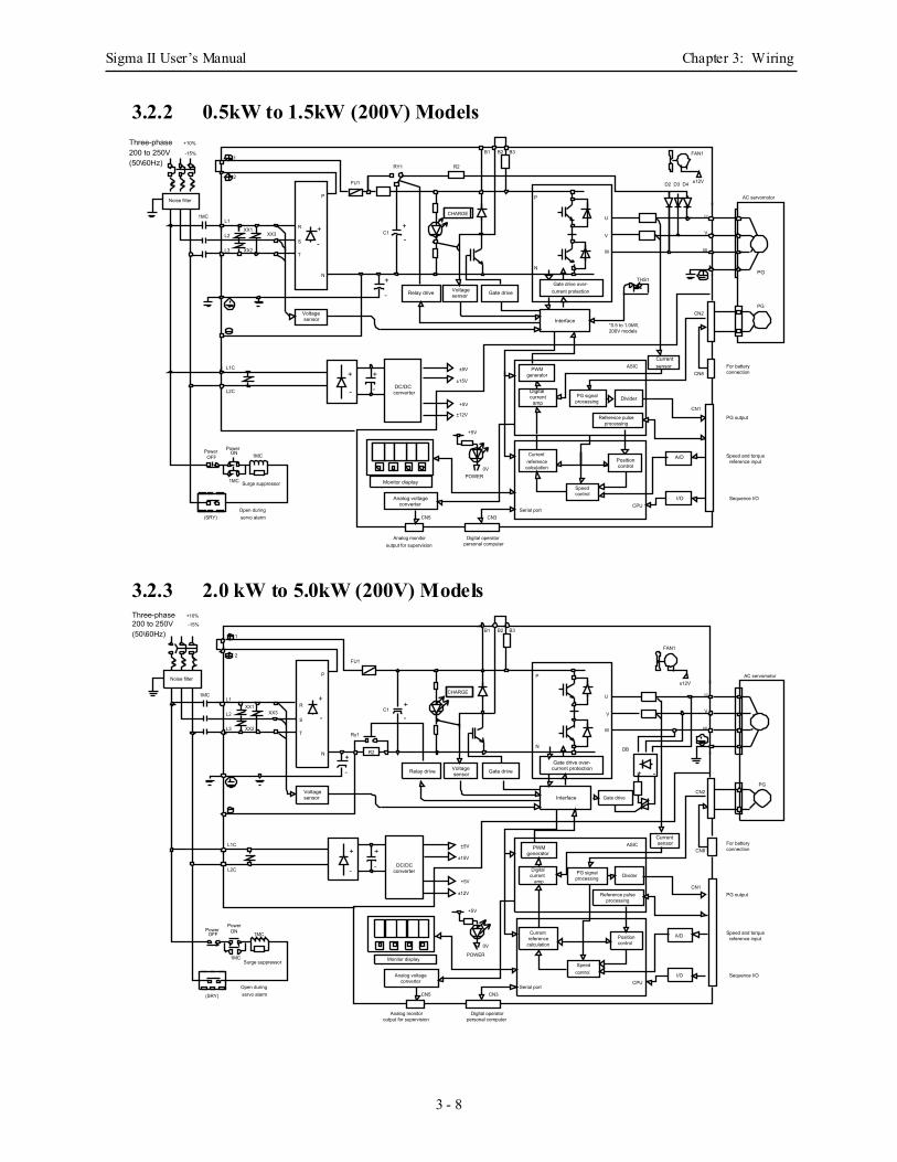
3.2.2 0.5kW to 1.5kW (200V) Models
3.2.3 2.0 kW to 5.0kW (200V) Models
Relay drive
Voltagesensor
Voltagesensor Gate drive
Currentsensor
DC/DCconverter
Analog voltageconverter
A/D
I/O
PG
Monitor display
Interface
` `
Positioncontrol
Digitalcurrent
ampDividerPG signal
processing
Currentreference
calculation
Speedcontrol
PWMgenerator
Reference pulseprocessing
Gate drive over-current protection
B1 B2 B3
CHARGE
XX3XX1
XX2
L1
L2
L3
1MC
Noise filter
2
1
+
-C1
R2RY1
FU1
+
-
+
-
P
N
R
S
T
+5V
±5V
±15V
+5V
±12V
0VPOWER
+
-
+
-
CN3CN5
L1C
L2C
Power OFF
PowerON 1MC
1MC Surge suppressor
Open during servo alarm(SRY)
FAN1
±12VD2 D3 D4
W
V
U
W
V
U
AC servomotor
CN2
CN8For batteryconnection
PG
ASIC
*0.5 to 1.0kW,200V models
THS1
CN1
PG output
Sequence I/OCPU
Serial port
P
N
Analog monitoroutput for supervision
Digital operatorpersonal computer
Speed and torquereference input
+10%
-15%
Three-phase200 to 250V(50\60Hz)
Relay drive
PWMgenerator
Voltagesensor
Voltagesensor Gate drive
Interface
Currentsensor
Gate drive over-current protection
DC/DCconverter Digital
currentamp
Divider
Reference pulseprocessing
Positioncontrol
Speedcontrol
PG signalprocessing
Currentreference
calculation
Analog voltageconverter
I/O
``
`
Monitor display
R2
A/D
XX3XX1
XX2
L1
L2
L3
1MC
Noise filter
2
1
+
-C1
FU1
P
N
R
S
T
+5V
±5V
±15V
+5V
±12V
0V
POWER
+
-
+
-
L1C
L2C
Power OFF
PowerON 1MC
1MCSurge suppressor
Open during servo alarm(SRY)
FAN1
±12V
W
V
U
W
V
U
AC servomotor
CN2
CN8For batteryconnection
PG
ASIC
CN1PG output
Sequence I/OCPU
Serial port
P
N
CHARGE+
-
B1 B2 B3
Gate drive
+ -
DB
+
-
CN3CN5
Ry1
Analog monitoroutput for supervision
Digital operatorpersonal computer
Speed and torquereference input
+10%
-15%
Three-phase200 to 250V(50\60Hz)
Sigma II User’s Manual Chapter 3: Wiring
3 - 9
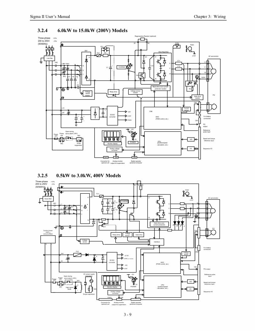
3.2.4 6.0kW to 15.0kW (200V) Models
3.2.5 0.5kW to 3.0kW, 400V Models
Currentsensor
Base drive over-currentprotection isolator
POWER
Analog voltageconverter
`
Monitor display
CHARGE
PM1/PM2/PM3
Regenerative Resistor (optional)
0V
R3
RY1
FU1
1MCL1
L2
L3
BA1
BA2
P
N
Line filter
Relay drive Voltage sensorisolator
+5V
+
_DC/DC
converter
+
_
±5V
±12V
PG5V
ASIC(PWM control, etc.)
CPU(position/speedcalculation, etc.)
CN8
CN1
CN2
`
`
AC servomotor
PG
For batteryconnection
U
SCR1
V
W
U
V
W
THS1
CT2
CT1
Gate driveisolator
A/D
I/O Sequence I/O
PGoutput
Referencepulse input
u
CN10 CN5 CN3
S
T
R
DB1
P
N
±12V
FAN1
D1
B1 B2
C10
+
_
+
_
Voltagesensor
isolator
- +
R2
TR1
C1+
_
C9
+
_
BA3
C7 C5C6
L1C
L2C
Open duringservo alarm (1RY)
1MC
Surgesuppressor
PowerON
1MC
PowerOFF
Connector foroptional unit
Analog monitoroutput for supervision personal computer
Digital operator
Speed and torquereference input
+10%
-15%
Three-phase200 to 250V(50\60Hz)
Gate drive over-current protection
`
XX3XX1
XX2
L1
L2
L3
1MC
Noise filter
2
1
RY1
FU1
P
N
R
S
T
FAN1
±12V
W
V
U
W
V
U
AC servomotor
CN2PG
P
N
+
-
B1 B2 B3
+
-
C2
C1
+
-
+
-+
-
+
-
DC/DCconverter
Analog voltageconverter
ASIC(PWM control, etc.)
CPU(position/speed
calculation, etc.)Monitor display
±7.5V
±15V (x 4 circuits)
+5V
±12V
CN8
CN1
+5V
0VPOWER
Relay driveVoltagesensor Gate drive
24V
0V
FU2
+
-
+
-
Voltagesensor
1MC
Surge suppressor
AC power supply(100/200V)
A/D
I/O
`
`
CHARGE
+ -
Control power+24V DC
(not provided)
Power OFF
PowerON
2RY
2RY
Open during servo alarm (1RY)
+
-High speed
diode
For batteryconnection
PG output
Speed and torquereference input
Sequence I/O
Reference pulse input
Voltagesensor
D1 +
-
+
-
+
-
D2 D3
Interface
Connector foroptional unit
CN10
Analog monitoroutput for supervision
CN5 CN3
personal computerDigital operator
+10%
-15%
Three-phase200 to 250V(50\60Hz)
Sigma II User’s Manual Chapter 3: Wiring
3 - 10
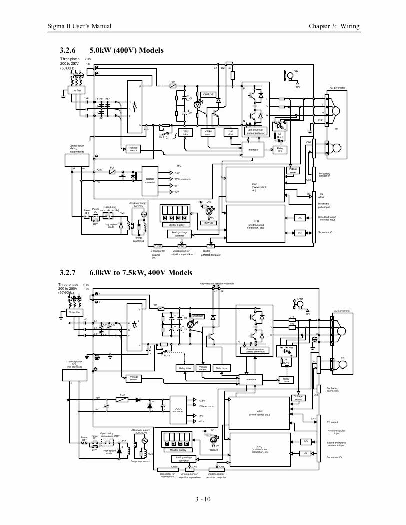
3.2.6 5.0kW (400V) Models
3.2.7 6.0kW to 7.5kW, 400V Models
POWER
Analog voltageconverter
Monitor display
Line filter
+
_ DC/DCconverter
Interface
Relaydr ive
Voltagesensor
Gatedrive
Voltagesensor
CHARGE
Voltagesensor
Relaydrive
I/O
A/D
Gate drive over-current protector
Control power+24VDC(not provided)
L1 BA1 BA3
L2
L3
BA2
1MC
1
2
R
S
T
N
P
FU1
B1 B3B2
P
FAN1
±12V AC servomotor
U
SCR1
w
V
PG
CN2
DBRLY2
U
W
V
N
C2
C1+—
+—
RY1
+—
+ — +24VFU1
+7.5V
BA2
+15V x 4 circuits
+5V
+12V
ASIC(PWM control,etc.)
CN8
CN1
Refer encepulse input
For batteryconnection
PGoutput
Speed and torquereference input
Sequence I/O
(position/speedcalculation, etc.)
CPU
+5V
0V
AC power supply100/200VOpen during
servo alar m (1RY)PowerOF F
PowerON
0V
1MC
2RY High-speeddiode
Surgesuppressor
CN10
Connector foroptionalunit
personal computerDigitaloperator
CN3
Analog monitoroutput for supervision
CN5
+10%
- 15%
Three-phase200 to 250V(50\60Hz)
`
XX3XX1
XX2
L1
L2
L3
1MC
Noise filter
2
1
RLY1
P
N
R
S
T
FAN1
±12V
W
V
U
AC servomotor
CN2PG
+
-
DC/DCconverter
Analog voltageconverter
ASIC(PWM control, etc.)
CPU(position/speed calculation, etc.)
Monitor display
CN8
CN1
+5V
0V
POWER
24V
0V
FU2
+
-
+
-
Voltagesensor
1MC
Surge suppressor
AC power supply(100/200V)
Interface
A/D
I/O
`
`
+ -
Control power+24V
DC(not provided)
Power OFF
PowerON
2RY
2RY
Open during servo alarm (1RY)
+
-High speed
diode
For batteryconnection
PG output
Speed and torquereference input
Sequence I/O
Reference pulse input
Regenerative resistor (optional)
Voltagesensor
B1 B2
CHARGE
FU1
+
-Gate drive over-current protection
W
V
U
P
N
- +DBRLY2
+
-
+
-+
-
+
-
C2
C1
CT2
CT1
Relaydrive
+7.5V
+15V (x 4 circu its)
+5V
±12V
Relay drive Voltagesensor Gate drive
CN10
Connector foroptional unit
CN5
Analog monitoroutput for supervision personal computer
Digital operator
CN3
+10%
-15%
Three-phase200 to 250V(50\60Hz)
Sigma II User’s Manual Chapter 3: Wiring
3 - 11
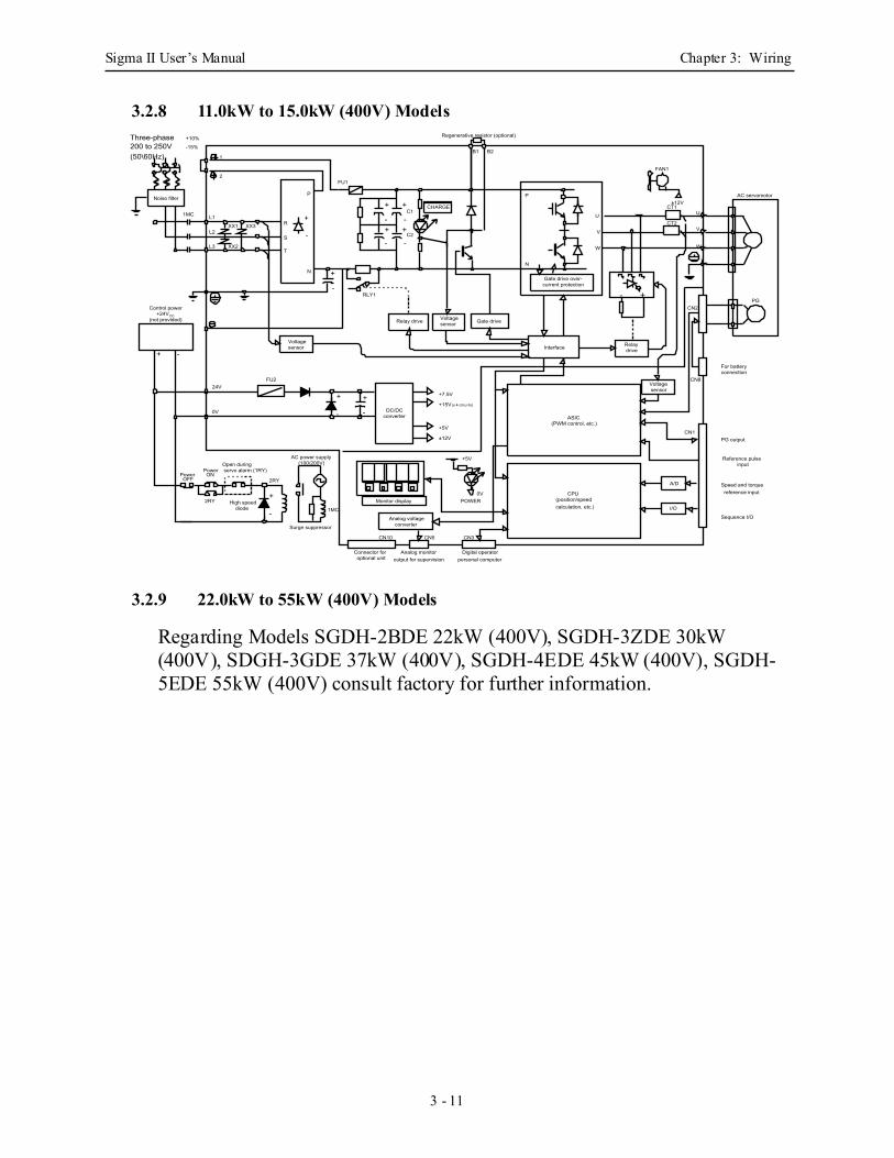
3.2.8 11.0kW to 15.0kW (400V) Models
3.2.9 22.0kW to 55kW (400V) Models
Regarding Models SGDH-2BDE 22kW (400V), SGDH-3ZDE 30kW (400V), SDGH-3GDE 37kW (400V), SGDH-4EDE 45kW (400V), SGDH-5EDE 55kW (400V) consult factory for further information.
XX3XX1
XX2
L1
L2
L3
1MC
Surge suppressor
AC power supply(100/200V)
Interface+ -
Control power+24V DC
(not provided)
Power OFF
PowerON
2RY
2RY
Open during servo alarm (1RY)
+
-High speed
diode
For batteryconnection
PG output
Speed and torquereference input
Sequence I/O
Reference pulse input
Voltagesensor
Gate drive over-current protection
W
V
U
P
N
+
-
+
-+
-
+
-
Relay drive Voltagesensor Gate drive
Relaydrive
- +CN2
`
AC servomotor
PG
`
`
CN8Voltagesensor
A/D
I/O
CN1
±12V
W
V
U
CT2
CT1
FAN1
ASIC(PWM control, etc.)
CPU(position/speed calculation, etc.)
Analog voltageconverter
Monitor display
DC/DCconverter
+
-
+7.5V
+15V (x 4 circu its)
+5V
±12V
24V
0V
FU2
+
-
+
-RLY1
1MC
Noise filter
2
1
FU1
P
N
R
S
T
+
-
CHARGE
C2
C1
Regenerative resistor (optional)
B1 B2
+5V
0VPOWER
CN10
Connector foroptional unit
Analog monitoroutput for supervision
CN5 CN3
personal computerDigital operator
+10%
-15%
Three-phase200 to 250V(50\60Hz)

Sigma II User’s Manual Chapter 3: Wiring
3 - 12
3.3 Main Circuit WiringThis section shows typical examples of main circuit wiring for Sigma II Series servo products, functions of main circuit terminals, and the power ON sequence.
Observe the following precautions when wiring.
• Do not bundle or run power and signal lines together in the same duct. Keep power and signal lines separated by at least 11.81in (30cm)Not doing so may cause a malfunction.
• Use twisted pair wires or multi-core shielded-pair wires for signal and encoder (PG) feedback lines.out of control or malfunction.The maximum length is 118.11in (3m) for reference input lines and is (787.40in (20m) out of control or malfunction.
• Do not touch the power terminals for 5 minutes after turning power OFF because high voltage may still remain in the servo amplifier.
• Avoid frequently turning power ON and OFF. Do not turn power ON or OFF more than once per minute.Since the servo amplifier has a capacitor in the power supply, a high charging current flows for 0.2s when power is turned ON. Frequently turning power ON and OFF causes main power devices like capacitors and fuses to deteriorate, resulting in unexpected problems.
• Suitable for use on a circuit capable of delivering not more than 5000Ar ms (symmetrical), 240V maximum. Must be used with UL listed fuses or circuit breakers, in accordance with the National Electrical Code.
• Required for 7.5kW -15kW (200V) or 6kW-15kW (400V) amplifiers:Must use ring terminals specified in Yaskawa Kits JZSP-CKT75, JZSP-CKT1E, JZSP-CKT75DE, JZSP-CKT1ADE, and JZSP-CKT1EDE for wiring of input and output power. Contact Yaskawa for details.
CAUTION
Sigma II User’s Manual Chapter 3: Wiring
3 - 13
3.3.1 Names and Descriptions of Main Circuit Terminal
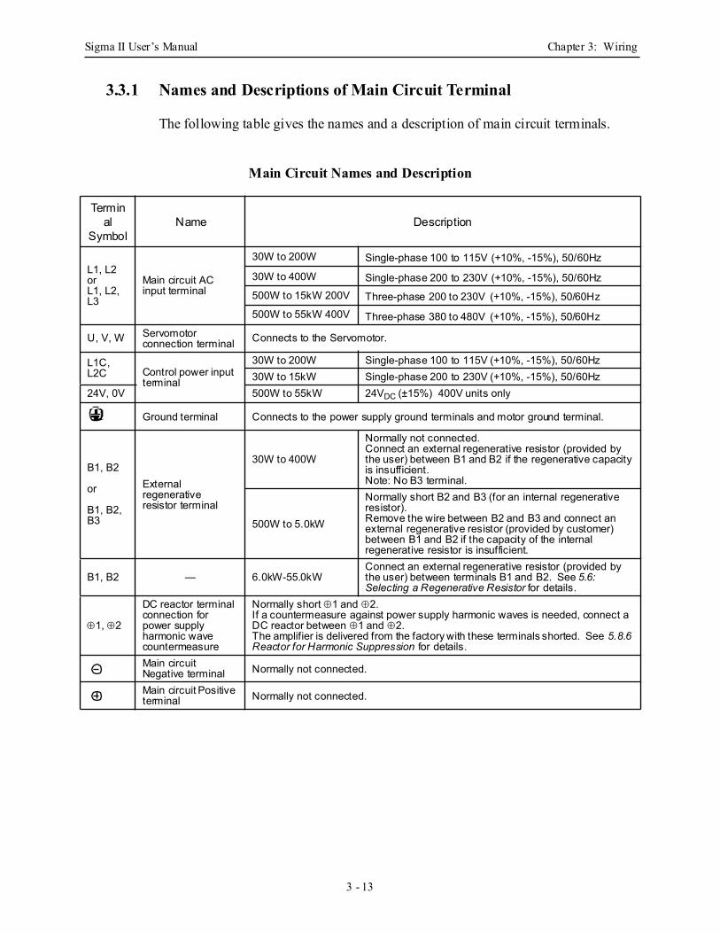
The following table gives the names and a description of main circuit terminals.
Main Circuit Names and Description
Terminal
SymbolName Description
L1, L2 orL1, L2, L3
Main circuit AC input terminal
30W to 200W Single-phase 100 to 115V (+10%, -15%), 50/60Hz
30W to 400W Single-phase 200 to 230V (+10%, -15%), 50/60Hz500W to 15kW 200V Three-phase 200 to 230V (+10%, -15%), 50/60Hz500W to 55kW 400V Three-phase 380 to 480V (+10%, -15%), 50/60Hz
U, V, W Servomotor connection terminal Connects to the Servomotor.
L1C, L2C Control power input
terminal
30W to 200W Single-phase 100 to 115V (+10%, -15%), 50/60Hz30W to 15kW Single-phase 200 to 230V (+10%, -15%), 50/60Hz
24V, 0V 500W to 55kW 24VDC (±15%) 400V units only
Ground terminal Connects to the power supply ground terminals and motor ground terminal.
B1, B2
or
B1, B2, B3
External regenerative resistor terminal
30W to 400W
Normally not connected.Connect an external regenerative resistor (provided by the user) between B1 and B2 if the regenerative capacity is insufficient.Note: No B3 terminal.
500W to 5.0kW
Normally short B2 and B3 (for an internal regenerative resistor).Remove the wire between B2 and B3 and connect an external regenerative resistor (provided by customer) between B1 and B2 if the capacity of the internal regenerative resistor is insufficient.
B1, B2 — 6.0kW-55.0kWConnect an external regenerative resistor (provided by the user) between terminals B1 and B2. See 5.6: Selecting a Regenerative Resistor for details.
⊕1, ⊕2
DC reactor terminal connection for power supply harmonic wave countermeasure
Normally short ⊕1 and ⊕2.If a countermeasure against power supply harmonic waves is needed, connect a DC reactor between ⊕1 and ⊕2.The amplifier is delivered from the factory with these terminals shorted. See 5.8.6 Reactor for Harmonic Suppression for details.
Main circuit Negative terminal Normally not connected.
Main circuit Positive terminal Normally not connected.
Sigma II User’s Manual Chapter 3: Wiring
3 - 14
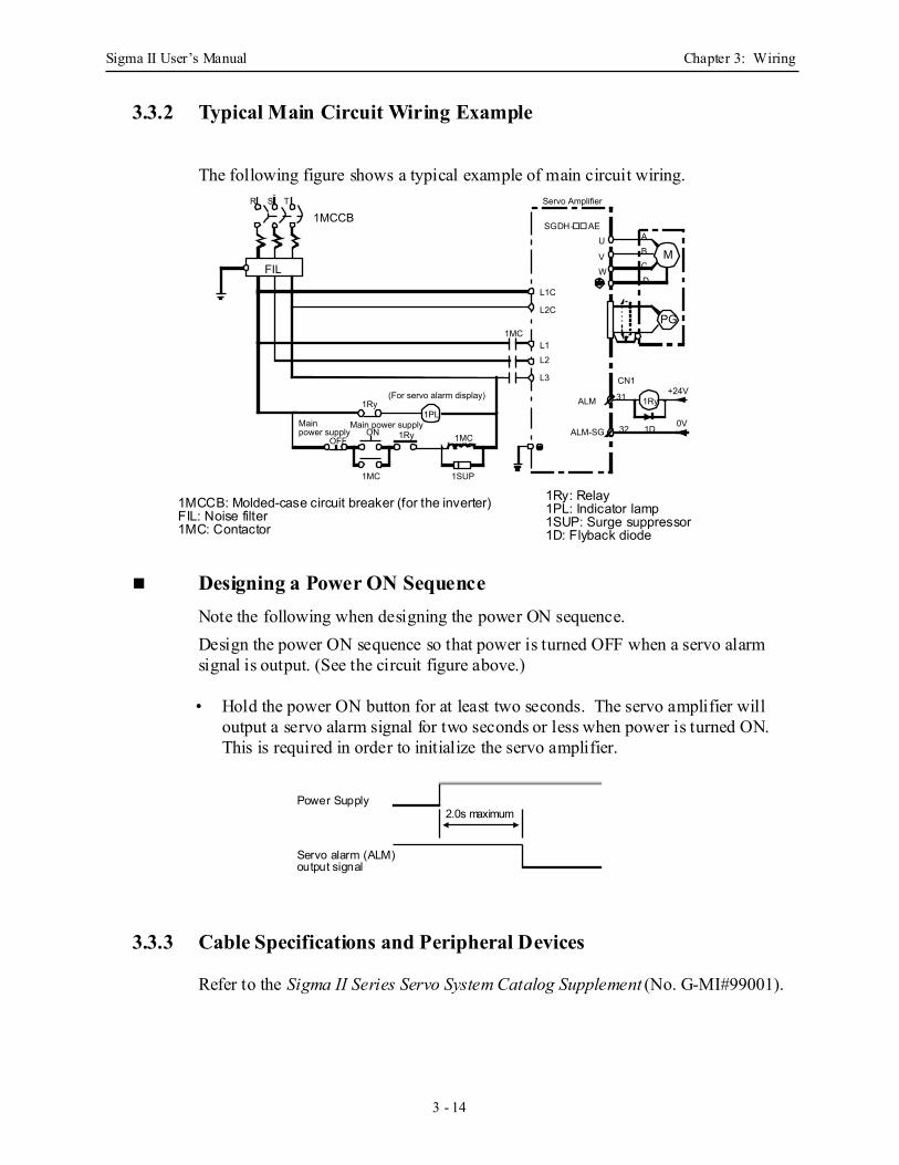
3.3.2 Typical Main Circuit Wiring Example
The following figure shows a typical example of main circuit wiring.
Designing a Power ON Sequence Note the following when designing the power ON sequence.Design the power ON sequence so that power is turned OFF when a servo alarm signal is output. (See the circuit figure above.)
• Hold the power ON button for at least two seconds. The servo amplifier will output a servo alarm signal for two seconds or less when power is turned ON. This is required in order to initialize the servo amplifier.
3.3.3 Cable Specifications and Peripheral Devices
Refer to the Sigma II Series Servo System Catalog Supplement (No. G-MI#99001).
1MCCB: Molded-case circuit breaker (for the inverter)FIL: Noise filter1MC: Contactor
1Ry: Relay1PL: Indicator lamp1SUP: Surge suppressor1D: Flyback diode
MFIL
1Ry
Main power supplyON 1RyOFF 1MC
1MC
(For servo alarm display)
1SUP
1MCL1L2
L3
L1C
L2C
Servo Amplifier
U
VW
ABCD
PG
CN1
31 +24VALM
ALM-SG 32 1D 0V
1Ry
1MCCBR S T
1PLMain power supply
SGDH- AE
Power Supply
Servo alarm (ALM)output signal
2.0s maximum
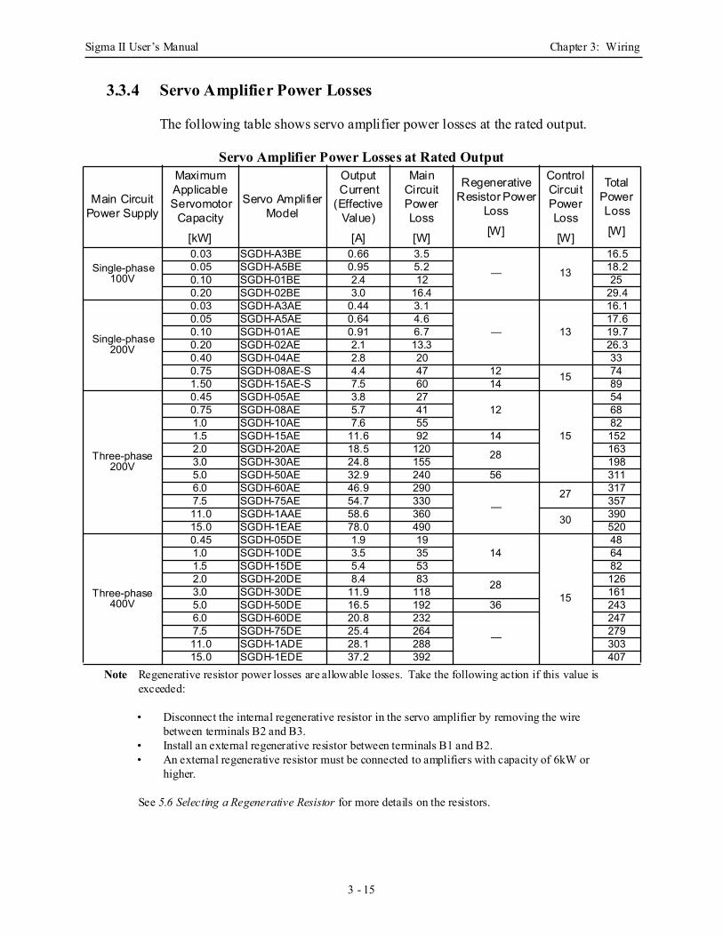
Sigma II User’s Manual Chapter 3: Wiring
3 - 15
3.3.4 Servo Amplifier Power Losses
The following table shows servo amplifier power losses at the rated output.
Servo Amplifier Power Losses at Rated Output
Note Regenerative resistor power losses are allowable losses. Take the following action if this value is exceeded:
• Disconnect the internal regenerative resistor in the servo amplifier by removing the wire between terminals B2 and B3.
• Install an external regenerative resistor between terminals B1 and B2.• An external regenerative resistor must be connected to amplifiers with capacity of 6kW or
higher.
See 5.6 Selecting a Regenerative Resistor for more details on the resistors.
Main Circuit Power Supply
Maximum Applicable Servomotor
Capacity[kW]
Servo Amplifier Model
Output Current
(Effective Value)
[A]
Main Circuit Power Loss[W]
Regenerative Resistor Power
Loss[W]
Control Circuit Power Loss[W]
Total Power Loss[W]
Single-phase 100V
0.03 SGDH-A3BE 0.66 3.5
— 13
16.50.05 SGDH-A5BE 0.95 5.2 18.20.10 SGDH-01BE 2.4 12 250.20 SGDH-02BE 3.0 16.4 29.4
Single-phase 200V
0.03 SGDH-A3AE 0.44 3.1
— 13
16.10.05 SGDH-A5AE 0.64 4.6 17.60.10 SGDH-01AE 0.91 6.7 19.70.20 SGDH-02AE 2.1 13.3 26.30.40 SGDH-04AE 2.8 20 330.75 SGDH-08AE-S 4.4 47 12 15 741.50 SGDH-15AE-S 7.5 60 14 89
Three-phase 200V
0.45 SGDH-05AE 3.8 2712
15
540.75 SGDH-08AE 5.7 41 681.0 SGDH-10AE 7.6 55 821.5 SGDH-15AE 11.6 92 14 1522.0 SGDH-20AE 18.5 120 28 1633.0 SGDH-30AE 24.8 155 1985.0 SGDH-50AE 32.9 240 56 3116.0 SGDH-60AE 46.9 290
—27 317
7.5 SGDH-75AE 54.7 330 35711.0 SGDH-1AAE 58.6 360 30 39015.0 SGDH-1EAE 78.0 490 520
Three-phase 400V
0.45 SGDH-05DE 1.9 1914
15
481.0 SGDH-10DE 3.5 35 641.5 SGDH-15DE 5.4 53 822.0 SGDH-20DE 8.4 83 28 1263.0 SGDH-30DE 11.9 118 1615.0 SGDH-50DE 16.5 192 36 2436.0 SGDH-60DE 20.8 232
—
2477.5 SGDH-75DE 25.4 264 27911.0 SGDH-1ADE 28.1 288 30315.0 SGDH-1EDE 37.2 392 407
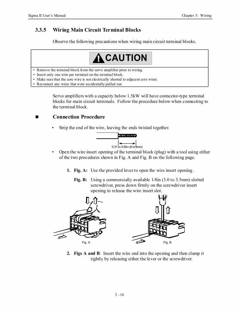
Sigma II User’s Manual Chapter 3: Wiring
3 - 16
3.3.5 Wiring Main Circuit Terminal Blocks
Observe the following precautions when wiring main circuit terminal blocks.
Servo amplifiers with a capacity below 1.5kW will have connector-type terminal blocks for main circuit terminals. Follow the procedure below when connecting to the terminal block.
Connection Procedure
• Strip the end of the wire, leaving the ends twisted together.
• Open the wire insert opening of the terminal block (plug) with a tool using either of the two procedures shown in Fig. A and Fig. B on the following page.
1. Fig. A: Use the provided lever to open the wire insert opening .
Fig. B: Using a commercially available 1/8in (3.0 to 3.5mm) slotted screwdriver, press down firmly on the screwdriver insert opening to release the wire insert slot.
2. Figs A and B: Insert the wire end into the opening and then clamp it tightly by releasing either the lever or the screwdriver.
• Remove the terminal block from the servo amplifier prior to wiring.• Insert only one wire per terminal on the terminal block.• Make sure that the core wire is not electrically shorted to adjacent core wires.• Reconnect any wires that were accidentally pulled out.
CAUTION
0.31 to 0.35in (8 to 9mm)
Fig. A Fig. B
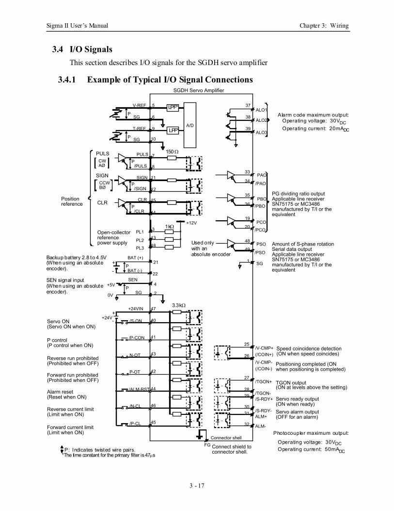
Sigma II User’s Manual Chapter 3: Wiring
3 - 17
3.4 I/O SignalsThis section describes I/O signals for the SGDH servo amplifier
3.4.1 Example of Typical I/O Signal Connections
~
~
~
~
~
~
~
~
~
~
~
~
~
A/D
PULSCWAØ
SIGNCCWBØ
CLR
P
P
P
P
P
P
P
V-REF
T-REF
SG
SG
5
6
9
10
PULS
/PULS
SIGN
/SIGN
CLR
/CLR
7
8
11
15
12
14
+-
+5V
0V
BAT (+)
BAT (-)
SEN
SG
+24VIN
+24VServo ON (Servo ON when ON)
P control (P control when ON)
Reverse run prohibited (Prohibited when OFF)
Forward run prohibited (Prohibited when OFF)
Alarm reset (Reset when ON)
Reverse current limit (Limit when ON)
Forward current limit (Limit when ON)
+- /S-ON
/P-CON
N-OT
P-OT
/ALM-RST
/N-CL
/P-CL
21
22
4
2
47
40
41
43
42
44
45
46
Connector shell
Connect shield to connector shell.
ALO1
ALO2
ALO3
PAO
PBO
PCO
/PAO
/PBO
/PCO
PG dividing ratio output Applicable line receiverSN75175 or MC3486 manufactured by T/I or the equivalent
/PSO
PSO Amount of S-phase rotationSerial data output Applicable line receiverSN75175 or MC3486 manufactured by T/I or the equivalent
SG
/V-CMP+(/COIN+)
/V-CMP-(/COIN-)
/TGON+
/TGON-/S-RDY+
/S-RDY-ALM+
ALM-
Speed coincidence detection (ON when speed coincides)
Positioning completed (ON when positioning is completed)
TGON output (ON at levels above the setting)
Servo ready output (ON when ready) Servo alarm output (OFF for an alarm)
37
38
39
33
34
35
36
19
20
48
49
1
25
26
27
28
31
29
30
32
FG
PL1
PL2
PL3
+12V
Open-collector reference power supply
SGDH Servo Amplifier
3
13
18
~
Position reference
Alarm code maximum output:Operating voltage: 30VDC
Photocoupler maximum output:
Operating voltage: 30VDCOperating current: 50mADC
Used only
3.3kΩ
150 Ω
1kΩ
LPF*
LPF*
Backup battery 2.8 to 4.5V(When using an absoluteencoder).
SEN signal input(When using an absoluteencoder).
P: Indicates twisted wire pairs.*The time constant for the primary filter is 47µs
with an absolute encoder
Operating current: 20mADC
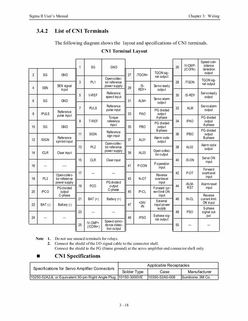
Sigma II User’s Manual Chapter 3: Wiring
3 - 18
3.4.2 List of CN1 Terminals
The following diagram shows the layout and specifications of CN1 terminals.
CN1 Terminal Layout
Note 1. Do not use unused terminals for relays.2. Connect the shield of the I/O signal cable to the connector shell.
Connect the shield to the FG (frame ground) at the servo amplifier-end connector shell only.
CN1 Specifications
1 SG GND 26 /V-CMP-(/COIN-)
Speed coin-cidence de tection output2 SG GND 27 /TGON+ TGON sig -
nal outpu t3 PL1
Open-collec-tor reference power supply
28 /TGON TGON sig-nal output
4 SEN SEN signal input 29 /S-
RDY+Servo ready
outpu t5 V-REF Reference
speed input 30 /S-RDY Servo ready output
6 SG GND 31 ALM+ Servo alarmoutpu t
7 PULS Reference pulse input 32 ALM Servo alarm
output8 /PULS Reference
pulse inpu t 33 PAOPG divided
outpu t A-phase
9 T-REFTorque
reference inpu t
34 /PAOPG divided
output A-phase10 SG GND 35 PBO
PG divided outpu t
B-phase11 SIGN Reference
sign input 36 /PBOPG divided
output B-phase12 /SIGN Reference
symbol input 37 AL01 Alarm codeoutpu t
13 PL2Open-collec-tor reference power supply
38 AL02 Alarm code output
14 /CLR Clear inpu t 39 AL03 Open-collec-tor output
15 CLR Clear input 40 /S-ON Servo ON input
16 — —- 41 P-CON P operation input
17 — — 42 P-OTForward
overtravel input18 PL3
Open-collec-tor reference power supply
43 N-OTReverse
overtravel input
19 PCOPG divided
output C-phase
44 /ALM-RST
Alarm reset input
20 /PCOPG d ivided
outputC-phase
45 /P-CLForward cur-ren t limit ON
input21 BAT (+) Batte ry (+) 46 /N-CL
Reverse current limit
ON input22 BAT (-) Battery (-) 47 +24V-IN
External input power
supply23 — — 48 PSO
S-phase signal out-
put24 — — 49 /PSO S-phase sig-nal outpu t
25 /V-CMP+(/COIN+)
Speed coinci-dence detec-tion ou tput
50 — —
Specifications for Servo Amplifier ConnectorsApplicable Receptacles
Solder Type Case Manufacturer10250-52A2JL or Equivalent 50-pin Right Angle Plug 10150-3000VE 10350-52A0-008 Sumitomo 3M Co.
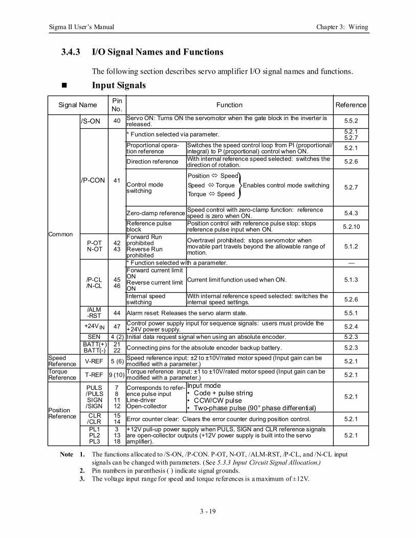
Sigma II User’s Manual Chapter 3: Wiring
3 - 19
3.4.3 I/O Signal Names and Functions
The following section describes servo amplifier I/O signal names and functions.
Input Signals
Note 1. The functions allocated to /S-ON, /P-CON. P-OT, N-OT, /ALM-RST, /P-CL, and /N-CL input signals can be changed with parameters. (See 5.3.3 Input Circuit Signal Allocation.)
2. Pin numbers in parenthesis ( ) indicate signal grounds.3. The voltage input range for speed and torque references is a maximum of ±12V.
Signal Name Pin No. Function Reference
Common
/S-ON 40 Servo ON: Turns ON the servomotor when the gate block in the inverter is released. 5.5.2
/P-CON 41
* Function selected via parameter. 5.2.15.2.7
Proportional opera-tion reference
Switches the speed control loop from PI (proportional/integral) to P (proportional) control when ON. 5.2.1
Direction reference With internal reference speed selected: switches the direction of rotation. 5.2.6
Control mode switching 5.2.7
Zero-clamp reference Speed control with zero-clamp function: reference speed is zero when ON. 5.4.3
Reference pulse block
Position control with reference pulse stop: stops reference pulse input when ON. 5.2.10
P-OTN-OT
4243
Forward Run prohibitedReverse Run prohibited
Overtravel prohibited: stops servomotor when movable part travels beyond the allowable range of motion.
5.1.2
/P-CL/N-CL
4546
* Function selected with a parameter. —Forward current limit ONReverse current limit ON
Current limit function used when ON. 5.1.3
Internal speed switching
With internal reference speed selected: switches the internal speed settings. 5.2.6
/ALM-RST 44 Alarm reset: Releases the servo alarm state. 5.5.1
+24VIN 47 Control power supply input for sequence signals: users must provide the +24V power supply. 5.2.4
SEN 4 (2) Initial data request signal when using an absolute encoder. 5.2.3BATT(+)BATT(-)
2122 Connecting pins for the absolute encoder backup battery. 5.2.3
SpeedReference V-REF 5 (6) Speed reference input: ±2 to ±10V/rated motor speed (Input gain can be
modified with a parameter.) 5.2.1TorqueReference T-REF 9 (10) Torque reference input: ±1 to ±10V/rated motor speed (Input gain can be
modified with a parameter.) 5.2.1
PositionReference
PULS/PULSSIGN/SIGN
781112
Corresponds to refer-ence pulse inputLine-driverOpen-collector
Input mode• Code + pulse string• CCW/CW pulse• Two-phase pulse (90° phase differential)
5.2.1
CLR/CLR
1514 Error counter clear: Clears the error counter during position control. 5.2.1
PL1PL2PL3
31318
+12V pull-up power supply when PULS, SIGN and CLR reference signals are open-collector outputs (+12V power supply is built into the servo amplifier).
5.2.1
Position Speed Speed Torque Enables control mode switchingTorque Speed
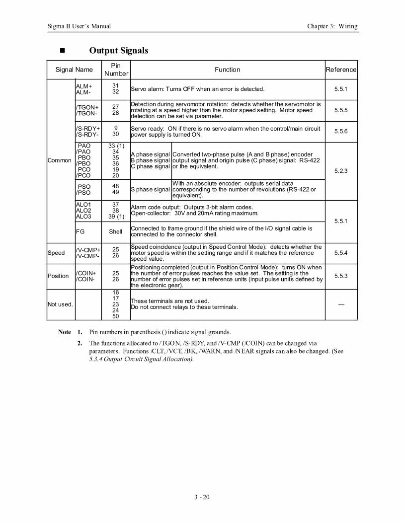
Sigma II User’s Manual Chapter 3: Wiring
3 - 20
Output Signals
Note 1. Pin numbers in parenthesis () indicate signal grounds.
2. The functions allocated to /TGON, /S-RDY, and /V-CMP (/COIN) can be changed via parameters. Functions /CLT, /VCT, /BK, /WARN, and /NEAR signals can also be changed. (See 5.3.4 Output Circuit Signal Allocation).
Signal Name Pin Number Function Reference
Common
ALM+ALM-
3132 Servo alarm: Turns OFF when an error is detected. 5.5.1
/TGON+/TGON-
2728
Detection during servomotor rotation: detects whether the servomotor is rotating at a speed higher than the motor speed setting. Motor speed detection can be set via parameter.
5.5.5
/S-RDY+/S-RDY-
930
Servo ready: ON if there is no servo alarm when the control/main circuit power supply is turned ON. 5.5.6
PAO/PAO PBO/PBO PCO/PCO
33 (1)3435361920
A phase signalB phase signalC phase signal
Converted two-phase pulse (A and B phase) encoder output signal and origin pulse (C phase) signal: RS-422 or the equivalent.
5.2.3
PSO/PSO
4849 S phase signal
With an absolute encoder: outputs serial data corresponding to the number of revolutions (RS-422 or equivalent).
ALO1ALO2ALO3
3738
39 (1)Alarm code output: Outputs 3-bit alarm codes.Open-collector: 30V and 20mA rating maximum.
5.5.1
FG Shell Connected to frame ground if the shield wire of the I/O signal cable is connected to the connector shell.
Speed /V-CMP+/V-CMP-
2526
Speed coincidence (output in Speed Control Mode): detects whether the motor speed is within the setting range and if it matches the reference speed value.
5.5.4
Position /COIN+/COIN-
2526
Positioning completed (output in Position Control Mode): turns ON when the number of error pulses reaches the value set. The setting is the number of error pulses set in reference units (input pulse units defined by the electronic gear).
5.5.3
Not used.
1617232450
These terminals are not used.Do not connect relays to these terminals. —
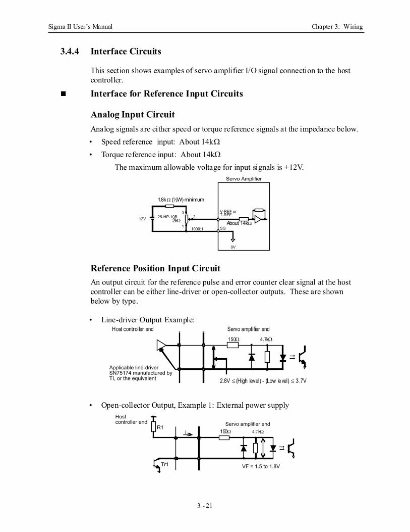
Sigma II User’s Manual Chapter 3: Wiring
3 - 21
3.4.4 Interface Circuits
This section shows examples of servo amplifier I/O signal connection to the host controller.
Interface for Reference Input Circuits
Analog Input Circuit Analog signals are either speed or torque reference signals at the impedance below.• Speed reference input: About 14kΩ
• Torque reference input: About 14kΩ
The maximum allowable voltage for input signals is ±12V.
Reference Position Input Circuit An output circuit for the reference pulse and error counter clear signal at the host controller can be either line-driver or open-collector outputs. These are shown below by type.
• Line-driver Output Example:
• Open-collector Output, Example 1: External power supply
12V 25-HP-10B 3
1
2
1000:1
0V
SG
Servo Amplifier
V-REF or T-REF
1.8k Ω (½W) minimum
2kΩ About 14kΩ
Applicable line-driver SN75174 manufactured by TI, or the equivalent
Servo amplifier endHost controller end150Ω 4.7kΩ
2.8V ≤ (High level) - (Low level) ≤ 3 .7V
VF = 1.5 to 1.8VTr1
R1i
Servo amplifier end Host controller end
150Ω 4.7kΩ
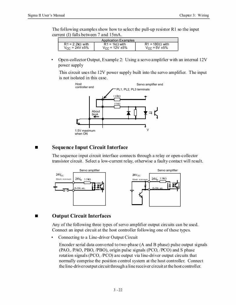
Sigma II User’s Manual Chapter 3: Wiring
3 - 22
The following examples show how to select the pull-up resistor R1 so the input current (I) falls between 7 and 15mA.
• Open-collector Output, Example 2: Using a servo amplifier with an internal 12V power supplyThis circuit uses the 12V power supply built into the servo amplifier. The input is not isolated in this case.
Sequence Input Circuit Interface The sequence input circuit interface connects through a relay or open-collector transistor circuit. Select a low-current relay, otherwise a faulty contact will result.
Output Circuit Interfaces Any of the following three types of servo amplifier output circuits can be used. Connect an input circuit at the host controller following one of these types.• Connecting to a Line-driver Output Circuit
Encoder serial data converted to two-phase (A and B phase) pulse output signals (PAO, /PAO, PBO, /PBO), origin pulse signals (PCO, /PCO) and S phase rotation signals (PCO, /PCO) are output via line-driver output circuits that normally comprise the position control system at the host controller. Connect the line-driver output circuit through a line receiver circuit at the host controller.
Application ExamplesR1 = 2.2kΩ withVCC = 24V ±5%
R1 = 1kΩ withVCC = 12V ±5%
R1 = 180Ω withVCC = 5V ±5%
PL1, PL2, PL3 terminals
V1.5V maximum when ON
About 9mA
Servo amplifier end Host controller end
1.0kΩ
150Ω
/S-ON, etc.
Servo amplifier Servo amplifier
/S-ON, etc.
24VDC
50m A m ini mum
24VDC
50mA m ini mum24VIN 24VIN3.3kΩ 3.3kΩ
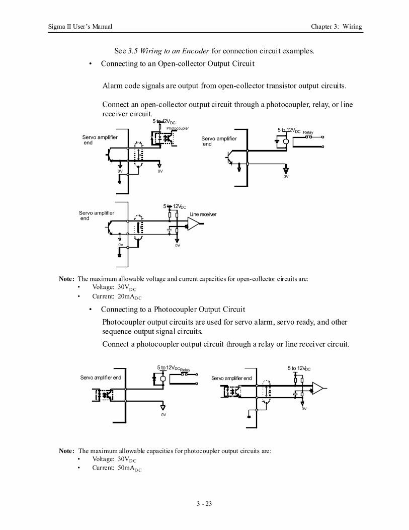
Sigma II User’s Manual Chapter 3: Wiring
3 - 23
See 3.5 Wiring to an Encoder for connection circuit examples.• Connecting to an Open-collector Output Circuit
Alarm code signals are output from open-collector transistor output circuits.
Connect an open-collector output circuit through a photocoupler, relay, or line receiver circuit.
Note: The maximum allowable voltage and current capacities for open-collector circuits are:• Voltage: 30VD C• Current: 20mAD C
• Connecting to a Photocoupler Output Circuit Photocoupler output circuits are used for servo alarm, servo ready, and other sequence output signal circuits.Connect a photocoupler output circuit through a relay or line receiver circuit.
Note: The maximum allowable capacities for photocoupler output circuits are:• Voltage: 30VD C • Current: 50mAD C
0V
P
0V
Photocoupler Relay
0V
P
0V 0V
Servo amplifier end
Servo amplifier end
Servo amplifier end
5 to 12VDC
5 to 12VDC
5 to 12VDC
Line receiver
0V
P
0V
Relay
Servo amplifier end
5 to 12VDC
Servo amplifier end
5 to 12VDC
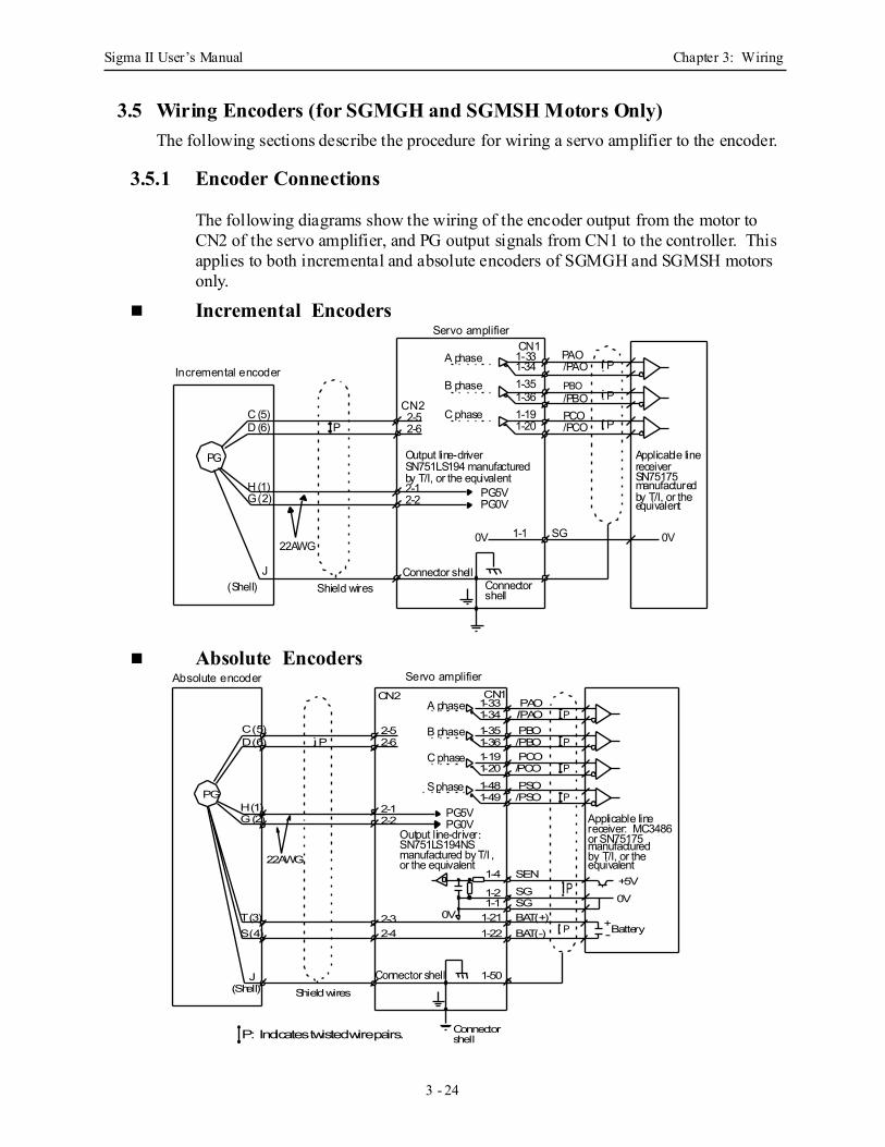
Sigma II User’s Manual Chapter 3: Wiring
3 - 24
3.5 Wiring Encoders (for SGMGH and SGMSH Motors Only)The following sections describe the procedure for wiring a servo amplifier to the encoder.
3.5.1 Encoder Connections
The following diagrams show the wiring of the encoder output from the motor to CN2 of the servo amplifier, and PG output signals from CN1 to the controller. This applies to both incremental and absolute encoders of SGMGH and SGMSH motors only.
Incremental Encoders
Absolute Encoders
Incremental encoder
Servo amplifier
Applicable lineOutput line-driverreceiverSN75175manufacturedby T/I, or theequivalent
A phase
B phase
C phaseCN2
PAOCN1
SN751LS194 manufacturedby T/I, or the equivalent
C (5)D (6)
H (1)G (2)
J
PG
2-52-6
2-12-2 PG5V
PG0V
P
1-331-341-351-361-191-20
/PAOPBO/PBOPCO/PCO
22AWG0V0V 1-1 SG
P
P
P
(Shell) ConnectorConnector shell
shellShield wires
P: Indicates twisted wire pairs.
Servo amplifier
Applicable lineOutput line-driver: receiver: MC3486
or SN75175manufacturedby T/I, or theequivalent
A phase
B phase
C phase
CN2 CN1
SN751LS194NS manufactured by T/I ,
PG2-12-2
PG5VPG0V
1-191-20
PCO/PCO P
(Shell)
Connector
Connector shell
shell
Shield wires
1-331-34
PAO/PAO P
1-351-36
PBO/PBO PP
2-52-6
1-21
1-50
0V0V
1-1 SGP +5V
SEN
SG1-2
1-4
1-222-32-4
C (5)D (6)
J
H (1)G (2)
T (3)S (4)
22AWG or the equivalent
1-481-49
PSO/PSO P
BAT(+)BAT(-)
+-P Battery
S phase
Absolute encoder
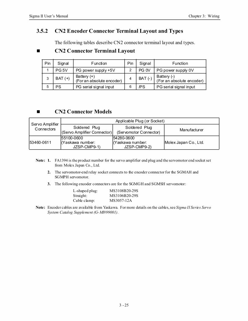
Sigma II User’s Manual Chapter 3: Wiring
3 - 25
3.5.2 CN2 Encoder Connector Terminal Layout and Types
The following tables describe CN2 connector terminal layout and types.
CN2 Connector Terminal Layout
CN2 Connector Models
Note: 1. FA1394 is the product number for the servo amplifier end plug and the servomotor end socket set from Molex Japan Co., Ltd.
2. The servomotor-end relay socket connects to the encoder connector for the SGMAH and SGMPH servomotor.
3. The following encoder connectors are for the SGMGH and SGMSH servomotor:
L-shaped plug: MS3108B20-29SStraight: MS3106B20-29SCable clamp: MS3057-12A
Note: Encoder cables are available from Yaskawa. For more details on the cables, see Sigma II Series Servo
System Catalog Supplement (G-MI#99001).
Pin Signal Function Pin Signal Function1 PG 5V PG power supply +5V 2 PG 0V PG power supply 0V
3 BAT (+) Battery (+)(For an absolute encoder) 4 BAT (-) Battery (-)
(For an absolute encoder)5 PS PG serial signal input 6 /PS PG serial signal input
Servo Amplifier Connectors
Applicable Plug (or Socket) Soldered Plug
(Servo Amplifier Connector)Soldered Plug
(Servomotor Connector) Manufacturer
53460-061155100-0600(Yaskawa number:
JZSP-CMP9-1)
54280-0600(Yaskawa number:
JZSP-CMP9-2)Molex Japan Co., Ltd.
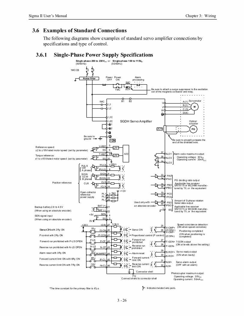
Sigma II User’s Manual Chapter 3: Wiring
3 - 26
3.6 Examples of Standard ConnectionsThe following diagrams show examples of standard servo amplifier connections by specifications and type of control.
3.6.1 Single-Phase Power Supply Specifications
Photocoupler maximum output:Operating vol tage: 30VDCOperating current: 50mA DC
3.3k Ω
1kΩ
Reference speed:±2 to ±10V/rated motor speed (set by parameter) Torque reference:±1 to ±10V/rated motor speed (set by parameter)
Alarm code maximum output:Operating vol tage: 30VDC
Backup battery 2.8 to 4 .5V(When using an absolute encoder).
SEN signal input(When using an absolute encoder).
Operating current: 20mAD C
P: Indicates twisted wire pa irs.*The time constant for the primary filter is 47µs
LPF*
1CN
PG
M
Noise filter
SGDH Servo Amplifier
Single-phase 200 to 230Va c or Single-phase 100 to 115Vac(50/60Hz) (50/60Hz)
1MCCB
Power Power
1MC
1MC
1MC
SUP
Alarm
Be sure to attach a surge suppressor to the excitation
B1 B2L1L2
U
V
L1CL2C
W
12
1CN
2CN
V-REFP SG
9
10
A/D
PULS/PULS
PULS
P
SIGN
CLR
7
/SIGNP
P
/CLR
PL1PL2
8
11
1215
14
31318
150Ω
PL3
+12V
38
39
3334
3536
1920
49
121
48
37
BAT (+)P
SEN
SG
2242
47
40
41
42
43
44
45
25
26
27
28
29
30
31
1Ry
2RY
P-LS
N-LS
3Ry
6Ry
7RY 46
P
BAT (-)
+24V
+5V
0V+24V
Used only withan absolute encoder
Servo ON
Proportional control (P contro l)
Forward run
Reverse run
Alarm reset
Forward current
/S-ON
/P-CON
P-OT
N-OT
/ALM-RST
/P-CL
/N-CL
/V-CMP+
/T-GON+
/S-RDY+/S-RDY-
/T-GON-
/V-CMP-
Reverse current
prohib ited
prohibi ted
l imit ON
limi t ON
ALO1ALO3
ALO3
PAO/PAO
PBO/PBO
PCO/PCO
PSO/PSO
SG
Amount of S-phase rotation
PG dividing ratio output
Be sure to properly prepare the
Optica l
coi l of the magnetic contactor and re lay.
end of the sh ielded wire.
Servomotor
encoder
Applicable l ine receiverSN75175 or MC3486 manufac-tured by T/I, or the equiva lent
Seria l data outputAppl icable line receiverSN75175 or MC3486 manufac-tured by T/I, or the equivalent
Position ing completed(ON when position ing iscompleted)
T-GON output
Servo ready output
Servo a larm output
(ON at levels above the setting)
(ON when ready)
(OFF with an a larm)
Connect sh ield to connector shell
Connector shel l
Forward run prohib ited wi th P-LS OPEN
Reverse run prohib ited wi th N-LS OPEN
Alarm reset wi th 3Ry ON
P control wi th 2Ry ON
Reverse current limit ON wi th 7Ry ON
Forward current l imit ON with 6Ry ON
Servo ON with 2Ry ON
Posi tion reference
Open-collector
SIGN
CW
CCW
CLR
B phase
referencepower supply
A phase
A (1)B (2)C (3)D (4)
Be sure toground
OFF ON processing
ALM+ALM-
FG
32
T-REF LPF*SG
5
6
P
(/COIN+)
(/COIN-)
Speed co incidence detection(ON when speed coincides)
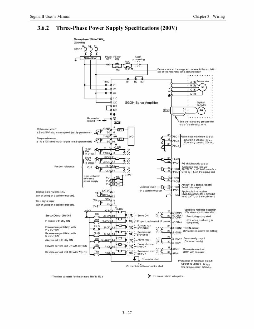
Sigma II User’s Manual Chapter 3: Wiring
3 - 27
3.6.2 Three-Phase Power Supply Specifications (200V)
Photocoupler maximum output:Operating vol tage: 30VDCOperating current: 50mADC
1kΩ
LPF*
LPF*Reference speed:±2 to ±10V/rated motor speed (set by parameter) Torque reference:±1 to ±10V/rated motor torque (set by parameter)
Alarm code maximum output:Operating voltage: 30VDC
Backup battery 2.8 to 4.5V(When using an absolute encoder).
SEN signal input(When using an absolute encoder).
Operating current: 20mADC
P: Ind icates twisted wire pa irs.*The time constant for the primary fi lter is 47µs
LPF*
1CN
PG
M
Noise filter
SGDH Servo Amplifier
Three-phase 200 to 230Vac(50/60Hz)
R S T1MCCB
Power Power
1MC
1MC
1MC
SUP
Alarm
Be sure to attach a surge suppressor to the excitation
B1 B2 B3L1L2
U
V
L1CL2C
L3 W
12
1CN
2CN
V-REFP SG
9
10
A/D
PULS/PULS
PULS
P
SIGN
CLR
7
/SIGNP
P
/CLR
PL1PL2
8
1112
15
14
31318
150Ω
PL3
+12V
38
39
3334
3536
1920
49
121
48
37
BAT (+)P
SEN
SG
2242
47
40
41
42
43
44
45
25
26
27
28
29
30
31
1Ry
2RY
P-LS
N-LS
3Ry
6Ry
7RY 46
P
BAT (-)
+24V
+5V
0V+24V
Used only withan absolute encoder
Servo ON
Proportional control (P control )Forward run
Reverse run
Alarm reset
Forward current
/S-ON
/P-CON
P-OT
N-OT
ALM-RST
P-CL
N-CL
/V-CMP+
/T-GON+
/S-RDY+/S-RDY-
/T-GON-
/V-CMP-
Reverse current
prohibi ted
prohibited
limit ON
limi t ON
ALO1ALO3
ALO3
PAO/PAO
PBO/PBO
PCO/PCO
PSO/PSO
SG
Amount of S-phase rotation
PG dividing ratio output
Optical
coil o f the magnetic contactor and relay.
Servomotor
encoder
Appl icable line receiverSN75175 or MC3486 manufac-tured by T/I, or the equiva lent
Seria l data outputApplicable line receiverSN75175 or MC3486 manufac-tured by T/I, or the equivalent
Posi tioning completed(ON when posi tioning iscompleted)
T-GON output
Servo ready output
Servo a larm output
(ON at levels above the setting)
(ON when ready)
(OFF with an a larm)
Connect shield to connector shell
Connector shel l
Forward run prohibited with
Reverse run prohibited with
Alarm reset with 3Ry ON
P control w ith 2Ry ON
Reverse current l imit ON with 7Ry ON
Forward current limi t ON with 6Ry ON
N-LS OPEN
P-LS OPEN
Servo ON with 2Ry ON
Position reference
Open-collector
SIGN
CW
CCW
CLR
B phase
referencepower supply
A phase
A (1)B (2)C (3)D (4)
Be sure toground
OFF ON processing
ALM+ALM-
3.3kΩ
FG
32
T-REFLPF*
SG
5
6
P
(/COIN+)
(/COIN-)
Speed coincidence detection(ON when speed coincides)
Be sure to properly prepare theend of the shielded wi re.

Sigma II User’s Manual Chapter 3: Wiring
3 - 28
3.6.3 Three-Phase Power Supply Specifications (400V)
Photocoupler maximum output:Operating vol tage: 30VDCOperating current: 50mADC
1kΩ
Reference speed:±2 to ±10V/rated motor speed (set by parameter) Torque reference:±1 to ±10V/rated torque (set by parameter)
Alarm code maximum output:Operating voltage: 30VDC
Backup battery 2.8 to 4.5V(When using an absolute encoder).
SEN signal input(When using an absolute encoder).
Operating current: 20mADC
P: Ind icates twisted wire pa irs.*The time constant for the primary fi lter is 47µs
LPF*
1CN
PG
M
Noise filter
SGDH Servo Amplifier
Three-phase 380 to 480Vac(50/60Hz)
R S T1MCCB
Power Power
1MC
1MC
1MC
SUP
Alarm
Be sure to attach a surge suppressor to the excitation
B1 B2 B3L1L2
U
V
+24V0V
L3 W
12
1CN
2CN
V-REFP SG
9
10
A/D
PULS/PULS
PULS
P
SIGN
CLR
7
/SIGNP
P
/CLR
PL1PL2
8
11
1215
14
31318
150Ω
PL3
+12V
38
39
3334
3536
1920
49
121
48
37
BAT (+)P
SEN
SG
2242
47
40
41
42
43
44
45
25
26
27
28
29
30
31
1Ry
2RY
P-LS
N-LS
3Ry
6Ry
7RY 46
P
BAT (-)
+24V
+5V
0V+24V
Used only withan absolute encoder
Servo ON
Proportional control (P control )
Forward run
Reverse run
Alarm reset
Forward current
/S-ON
/P-CON
P-OT
N-OT
ALM-RST
P-CL
N-CL
/V-CMP+
/T-GON+
/S-RDY+/S-RDY-
/T-GON-
/V-CMP-
Reverse current
prohibi ted
prohibited
limit ON
limi t ON
ALO1ALO3
ALO3
PAO/PAO
PBO/PBO
PCO/PCO
PSO/PSO
SG
Amount of S-phase rotation
PG dividing ratio output
Be sure to properly prepare the
Optical
coil o f the magnetic contactor and relay.
end of the shielded wi re.
Servomotor
encoder
Appl icable line receiverSN75175 or MC3486 manufac-tured by T/I, or the equiva lent
Seria l data outputApplicable line receiverSN75175 or MC3486 manufac-tured by T/I, or the equivalent
Posi tioning completed(ON when posi tioning iscompleted)
T-GON output
Servo ready output
Servo a larm output
(ON at levels above the setting)
(ON when ready)
(OFF with an a larm)
Connect shield to connector shell
Connector shel l
Forward run prohibited with
Reverse run prohibited with
Alarm reset with 3Ry ON
P control w ith 2Ry ON
Reverse current l imit ON with 7Ry ON
Forward current limi t ON with 6Ry ON
N-LS OPEN
P-LS OPEN
Servo ON with 2Ry ON
Position reference
Open-collector
SIGN
CW
CCW
CLR
B phase
referencepower supply
A phase
A (1)B (2)C (3)D (4)
Be sure toground
OFF ON processing
ALM+ALM-
3.3kΩ
FG
32
T-REF LPF*SG
5
6
P
(/COIN+)
(/COIN-)
Speed coincidence detection(ON when speed coincides)
24VD C ±15%
0V
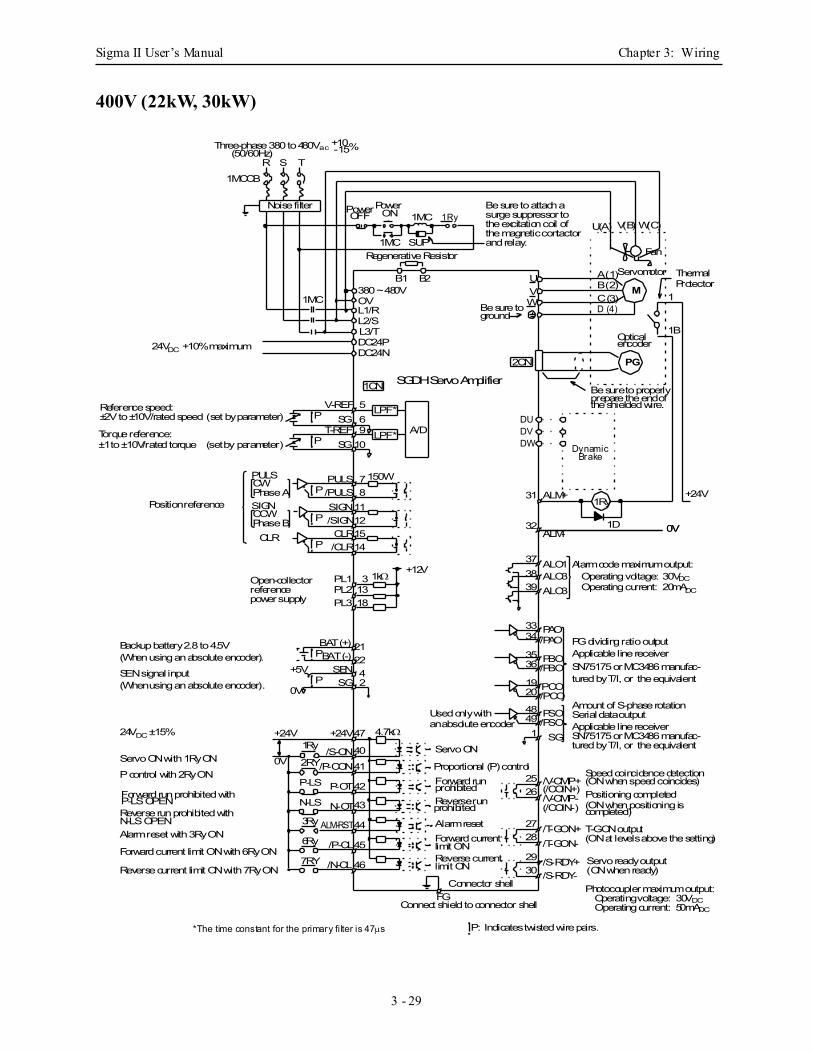
Sigma II User’s Manual Chapter 3: Wiring
3 - 29
400V (22kW, 30kW)
Servomotor
Fan
U(A) V(B) W(C)
P LPF*
P LPF*
Photocoupler maximum output:Operating voltage: 30VDCOperating current: 50mADC
Reference speed:±2V to ±10V/rated speed (set by parameter)
Torque reference:±1 to ±10V/rated torque (set by parameter)
Alarm code maximum output:Operating voltage: 30VDC
Backup battery 2.8 to 4.5V(When using an absolute encoder).
SEN signal input(When using an absolute encoder).
Operating current: 20mADC
P: Indicates twisted wire pairs.
1CN
PG
M
Noise filter
SGDH Servo Amplifier
Three-phase 380 to 480Vac(50/60Hz)
R S T
1MCCB
PowerPower1MC
1MC
1MC
SUP
Be sure to attach a
B1 B2
L1/RL2/S
UV
DC24PDC24N
L3/T
W
V-REF
910
A/D
PULS
/PULSPULS
P
SIGN
CLR
7
/SIGNP
P
/CLR
811121514
150W
3839
3334
3536
1920
491
48
37
BAT (+)P
SENSG
47
40
41
42
43
44
45
2526
2728
2930
31
46
P
BAT (-)
+24V
+5V
0V
+24V
Used only withan absolute encoder
Servo ON
Proportional (P) controlForward run
Reverse run
Alarm resetForward current
/S-ON/P-CON
P-OT
N-OT
ALM-RST
/P-CL
/N-CL
/V-CMP+
/T-GON+
/S-RDY+/S-RDY-
/T-GON-
/V-CMP-
Reverse current
prohibited
prohibited
limit ON
limit ON
ALO1ALO3ALO3
PAO/PAO
PBO/PBO
PCO/PCO
PSO/PSO
SG
Amount of S-phase rotation
PG dividing ratio output
Be sure to properly
Optical
prepare the end of
encoder
Applicable line receiverSN75175 or MC3486 manufac-tured by T/I, or the equivalent
Serial data outputApplicable line receiverSN75175 or MC3486 manufac-tured by T/I, or the equivalent
Positioning completed(ON when positioning iscompleted)
T-GON output
Servo ready output
(ON at levels above the setting)
(ON when ready)
Connect shield to connector shell
Connector shell
Forward run prohibited with
Reverse run prohibited with
Alarm reset with 3Ry ON
P control with 2Ry ON
Reverse current limit ON with 7Ry ON
Forward current limit ON with 6Ry ON
N-LS OPEN
P-LS OPEN
Servo ON with 1Ry ON
Position reference
CW
CLR
Phase A
A (1)B (2)C (3)D (4)Be sure to
ground
OFF ON 1Ry
ALM+
FG
56
(/COIN+)
(/COIN-)
Speed coincidence detection(ON when speed coincides)
24VDC ±15%
Regenerative Resistor
SGT-REF
SG
1Ry
2RY
P-LS
N-LS
3Ry
6Ry
7RY
4.7kΩ
the shielded wire.
1
1B
+24V1Ry
1D 0VALM-32
0V
+10-15%
24VDC +10% maximum
DU
DWDV
DynamicBrake
*The time constant for the primary filter is 47µs
2CN
SIGNCCWPhase B
surge suppressor to the excitation coil of the magnetic contactor and relay.
0V
1kΩPL1PL2
31318PL3
+12VOpen-collectorreferencepower supply
212242
ThermalProtector
OV380 ~ 480V
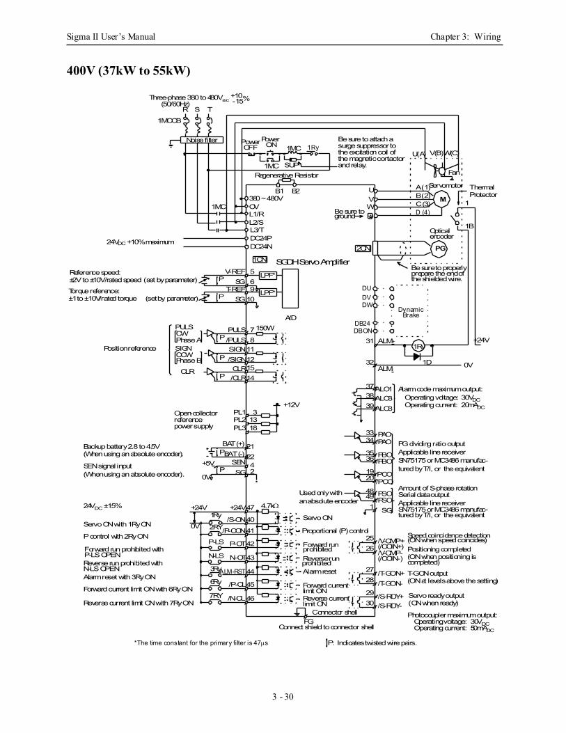
Sigma II User’s Manual Chapter 3: Wiring
3 - 30
400V (37kW to 55kW)
Photocoupler maximum output:Operating voltage: 30VDCOperating current: 50mADC
Reference speed:±2V to ±10V/rated speed (set by parameter)
Torque reference:±1 to ±10V/rated torque (set by parameter)
Alarm code maximum output:Operating voltage: 30VDCOperating current: 20mADC
P: Indicates twisted wire pairs.
1CN
PG
M
Noise filter
SGDH Servo Amplifier
Three-phase 380 to 480Vac(50/60Hz)
R S T
1MCCB
PowerPower1MC
1MC
1MC
SUP
Be sure to attach a
B1 B2
L1/RL2/S
UV
DC24PDC24N
L3/T
W
PULS
/PULSPULS
P
SIGN
CLR
7
/SIGNP
P
/CLR
811121514
150W
3839
3334
3536
1920
491
48
37
2526
2728
2930
31
Used only withan absolute encoder
Servo ON
Proportional (P) control
Forward run
Reverse run
Alarm reset
Forward current
/V-CMP+
/T-GON+
/S-RDY+/S-RDY-
/T-GON-
/V-CMP-
Reverse current
prohibited
prohibited
limit ON
limit ON
ALO1ALO3ALO3
PAO/PAO
PBO/PBO
PCO/PCO
PSO/PSO
SG
Amount of S-phase rotation
PG dividing ratio output
Be sure to properly
Optical
prepare the end of
Servomotor
encoder
Applicable line receiverSN75175 or MC3486 manufac-tured by T/I, or the equivalent
Serial data outputApplicable line receiverSN75175 or MC3486 manufac-tured by T/I, or the equivalent
Positioning completed(ON when positioning iscompleted)
T-GON output
Servo ready output
(ON at levels above the setting)
(ON when ready)
Connect shield to connector shell
Connector shell
Position reference
CW
CLR
Phase A
A (1)B (2)C (3)D (4)Be sure to
ground
OFF ON 1Ry
ALM+
FG
(/COIN+)
(/COIN-)
Speed coincidence detection(ON when speed coincides)
Fan
U(A) V(B)W(C)
Regenerative Resistor
the shielded wire.
1
1B
+24V1Ry
1D 0VALM-32
0V
+10-15%
DU
DWDV
DBONDB24
DynamicBrake
*The time constant for the primary filter is 47µs
2CN
SIGNCCWPhase B
surge suppressor to the excitation coil of the magnetic contactor and relay.
P LPF*
P LPF*
V-REF
910
56SG
T-REFSG
A/D
24VDC +10% maximum
PL1PL2
31318PL3
+12VOpen-collectorreferencepower supply
Backup battery 2.8 to 4.5V(When using an absolute encoder).
SEN signal input(When using an absolute encoder).
21BAT (+)P
SENSG
2242
47
40
41
42
43
44
45
46
P
BAT (-)
+24V
+5V
0V
+24V
/S-ON
/P-CON
P-OT
N-OT
ALM-RST
/P-CL
/N-CL
Forward run prohibited with
Reverse run prohibited with
Alarm reset with 3Ry ON
P control with 2Ry ON
Reverse current limit ON with 7Ry ON
Forward current limit ON with 6Ry ON
N-LS OPEN
P-LS OPEN
Servo ON with 1Ry ON
24VDC ±15%1Ry
2RY
P-LS
N-LS
3Ry
6Ry
7RY
4.7kΩ
380 ~ 480VOV
ThermalProtector
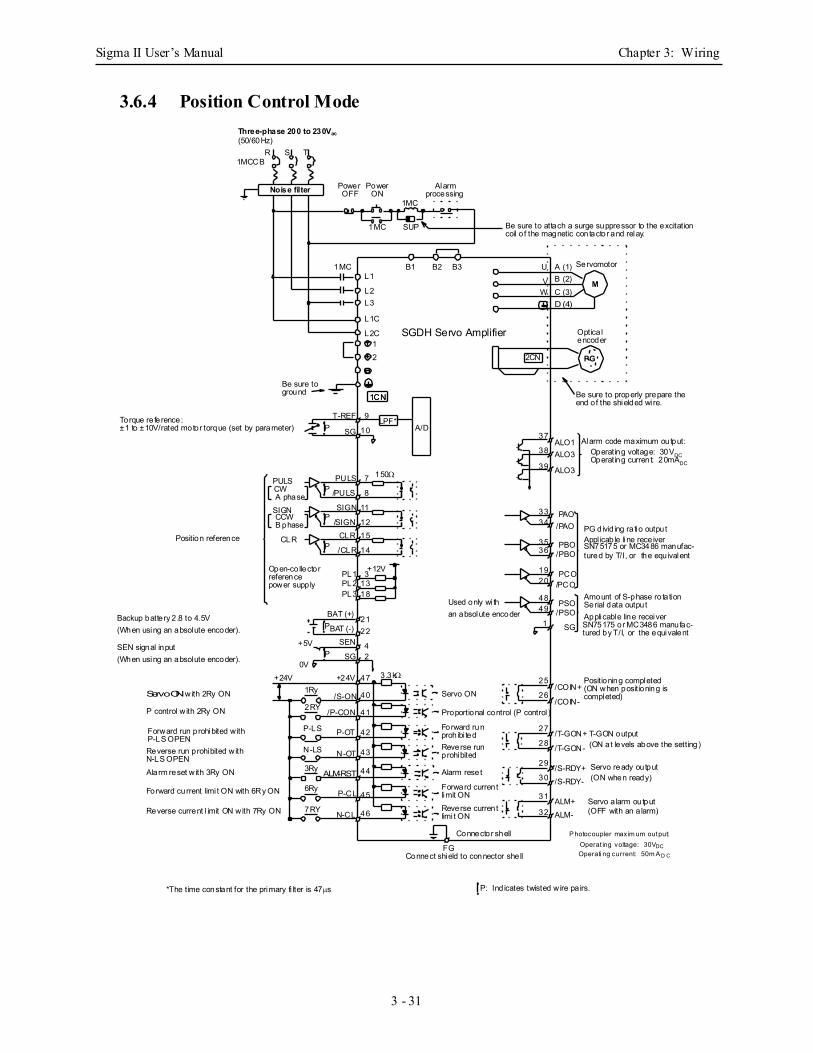
Sigma II User’s Manual Chapter 3: Wiring
3 - 31
3.6.4 Position Control Mode
Alarm code maximum output:Operating voltage: 30VDC
Photocoupler maxim um output:Operat ing voltage: 30VDCOperati ng current: 50m A D C
Backup battery 2.8 to 4.5V(When using an absolute encoder).
SEN signal input(When using an absolute encoder).
Operating current: 20mADC
P: Ind icates twisted wire pa irs.*The time constant for the primary fi lter is 47µs
Torque reference:±1 to ±10V/rated motor torque (set by parameter)
LPF*
1CN
PG
M
Noise filter
SGDH Servo Amplifier
Three-phase 200 to 230Vac(50/60Hz)
R S T1MCCB
Power Power
1MC
1MC
1MC
SUP
Alarm
Be sure to attach a surge suppressor to the excitation
B1 B2 B3L1
L2
U
V
L1C
L2C
L3W
12
1CN
2CN
T-REFP SG
9
10 A/D
PULS/PULS
PULS
P
SIGN
CLR
7
/SIGNP
P
/CLR
PL1PL2
8
11
1215
14
31318
150Ω
PL3
+12V
38
39
3334
3536
1920
49
121
48
37
BAT (+)P
SEN
SG
22
42
47
40
41
42
43
44
45
25
26
27
28
29
30
31
1Ry
2RY
P-LS
N-LS
3Ry
6Ry
7RY 46
P
BAT (-)
+24V
+5V
0V+24V
Used only wi than absolute encoder
Servo ON
Proportional control (P control )
Forward run
Reverse run
Alarm reset
Forward current
/S-ON
/P-CON
P-OT
N-OT
ALM-RST
P-CL
N-CL
/COIN+
/T-GON+
/S-RDY+/S-RDY-
/T-GON-
/COIN-
Reverse current
prohibi ted
prohibited
limit ON
limi t ON
ALO1ALO3
ALO3
PAO/PAO
PBO/PBO
PCO/PCO
PSO/PSO
SG
Amount of S-phase rotation
PG divid ing ra tio output
Optica l
coil o f the magnetic contactor and relay.
Servomotor
encoder
Appl icable line receiverSN75175 or MC3486 manufac-tured by T/I, or the equivalent
Serial data outputApplicable line receiverSN75175 or MC3486 manufac-tured by T/I, or the equivalent
Positioning completed(ON when positioning iscompleted)
T-GON output
Servo ready output
Servo a larm output
(ON at levels above the setting)
(ON when ready)
(OFF with an a larm)
Connect shield to connector shell
Connector shell
Forward run prohibited with
Reverse run prohibited with
Alarm reset with 3Ry ON
P control w ith 2Ry ON
Reverse current l imit ON with 7Ry ON
Forward current limi t ON with 6Ry ON
N-LS OPEN
P-LS OPEN
Servo ON with 2Ry ON
Position reference
Open-collector
SIGN
CW
CCW
CLR
B phase
referencepower supply
A phase
A (1)B (2)C (3)D (4)
Be sure toground
OFF ON processing
ALM+ALM-
3.3kΩ
FG
32
Be sure to properly prepare theend of the shielded wi re.
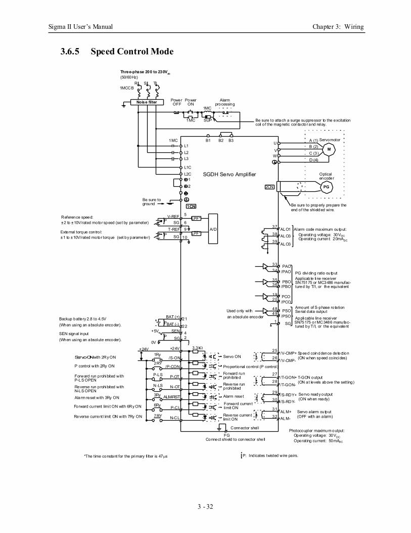
Sigma II User’s Manual Chapter 3: Wiring
3 - 32
3.6.5 Speed Control Mode
Photocoupler maximum output:Operating voltage: 30VDCOperating current: 50mADC
LPF*
LPF*Reference speed:±2 to ±10V/rated motor speed (set by parameter) External torque contro l:±1 to ±10V/rated motor torque (set by parameter)
Alarm code maximum output:Operating voltage: 30VDC
Backup battery 2.8 to 4.5V(When using an absolute encoder).
SEN signal input(When using an absolute encoder).
Operating current: 20mADC
P: Ind icates twisted wire pa irs.*The time constant for the primary fi lter is 47µs
LPF*
1CN
PG
M
Noise filter
SGDH Servo Amplifier
Three-phase 200 to 230Vac(50/60Hz)
R S T1MCCB
Power Power
1MC
1MC
1MC
SUP
Alarm
Be sure to attach a surge suppressor to the excitation
B1 B2 B3L1L2
U
V
L1CL2C
L3 W
12
1CN
2CN
V-REFP SG
9
10
A/D38
39
3334
3536
1920
49
121
48
37
BAT (+)P
SEN
SG
2242
25
26
27
28
29
30
31
1Ry
2RY
P-LS
N-LS
3Ry
6Ry
7RY
P
BAT (-)
+24V
+5V
0V+24V
Used only wi than absolute encoder
Servo ON
Proportional control (P control )Forward run
Reverse run
Alarm reset
Forward current
/S-ON
/P-CON
P-OT
N-OT
ALM-RST
P-CL
N-CL
/V-CMP+
/T-GON+
/S-RDY+/S-RDY-
/T-GON-
/V-CMP-
Reverse current
prohibi ted
prohibited
limit ON
limi t ON
ALO1ALO3
ALO3
PAO/PAO
PBO/PBO
PCO/PCO
PSO/PSO
SG
Amount of S-phase rotation
PG dividing ratio output
Be sure to properly prepare the
Optical
coil o f the magnetic contactor and relay.
end of the shielded wi re.
Servomotor
encoder
Appl icable line receiverSN75175 or MC3486 manufac-tured by T/I, or the equivalent
Serial data outputApplicable line receiverSN75175 or MC3486 manufac-tured by T/I, or the equivalent
T-GON output
Servo ready output
Servo a larm output
(ON at levels above the setting)
(ON when ready)
(OFF with an a larm)
Connect shield to connector shell
Connector shel l
Forward run prohibited with
Reverse run prohibited with
Alarm reset with 3Ry ON
P control w ith 2Ry ON
Reverse current l imit ON with 7Ry ON
Forward current limi t ON with 6Ry ON
N-LS OPEN
P-LS OPEN
Servo ON with 2Ry ON
A (1)B (2)C (3)D (4)
Be sure toground
OFF ON processing
ALM+ALM-
3.3kΩ
FG
32
T-REFLPF*
SG
5
6
P
Speed coincidence detection(ON when speed co incides)
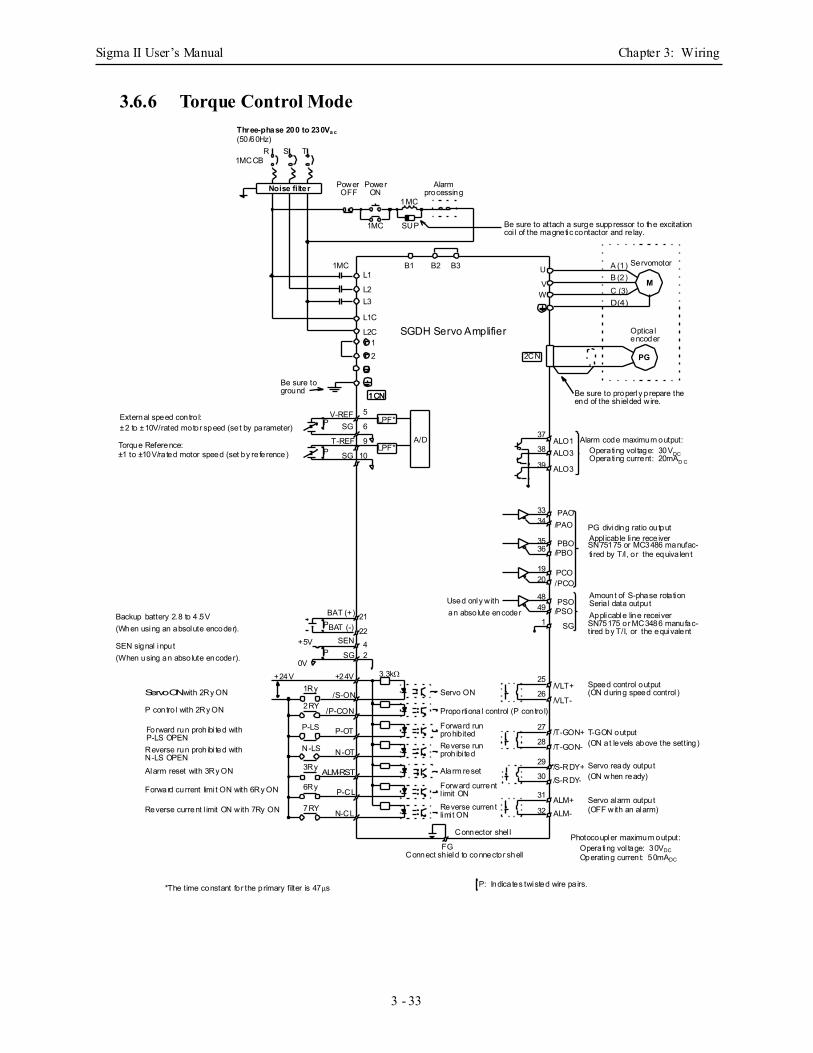
Sigma II User’s Manual Chapter 3: Wiring
3 - 33
3.6.6 Torque Control Mode
Photocoupler maximum output:Operating vol tage: 30VDCOperating current: 50mADC
LPF*
LPF*External speed contro l:±2 to ±10V/rated motor speed (set by parameter) Torque Reference: Alarm code maximum output:
Operating vol tage: 30VDC
Backup battery 2.8 to 4 .5V(When using an absolute encoder).
SEN signal input(When using an absolute encoder).
Operating current: 20mAD C
P: Indicates twisted wire pa irs.*The time constant for the primary filter is 47µs
LPF*
1CN
PG
M
Noise filter
SGDH Servo Amplifier
Three-phase 200 to 230Va c(50/60Hz)
R S T1MCCB
Power Power
1MC
1MC
1MC
SUP
Alarm
Be sure to attach a surge suppressor to the excitation
B1 B2 B3L1
L2
U
V
L1C
L2C
L3W
12
1CN
2CN
V-REFP SG
9
10
A/D38
39
3334
3536
1920
49
121
48
37
BAT (+)P
SEN
SG
2242
25
26
27
28
29
30
31
1Ry
2RY
P-LS
N-LS
3Ry
6Ry
7RY
P
BAT (-)
+24V
+5V
0V+24V
Used only withan absolute encoder
Servo ON
Proportional control (P contro l)
Forward run
Reverse run
Alarm reset
Forward current
/S-ON
/P-CON
P-OT
N-OT
ALM-RST
P-CL
N-CL
/VLT+
/T-GON+
/S-RDY+/S-RDY-
/T-GON-
/VLT-
Reverse current
prohib ited
prohibi ted
l imit ON
limi t ON
ALO1ALO3
ALO3
PAO/PAO
PBO/PBO
PCO/PCO
PSO/PSO
SG
Amount of S-phase rotation
PG dividing ratio output
Be sure to properly prepare the
Optica l
coi l of the magnetic contactor and re lay.
end of the sh ielded wire.
Servomotor
encoder
Appl icable line receiverSN75175 or MC3486 manufac-ti red by T/I, or the equiva lent
Seria l data outputApplicable line receiverSN75175 or MC3486 manufac-tired by T/I, or the equivalent
T-GON output
Servo ready output
Servo alarm output
(ON at levels above the setting)
(ON when ready)
(OFF with an alarm)
Connect sh ield to connector shell
Connector shel l
Forward run prohibi ted with
Reverse run prohibi ted with
Alarm reset with 3Ry ON
P contro l with 2Ry ON
Reverse current l imit ON with 7Ry ON
Forward current limi t ON with 6Ry ON
N-LS OPEN
P-LS OPEN
Servo ON with 2Ry ON
A (1)B (2)C (3)D (4)
Be sure toground
OFF ON processing
ALM+ALM-
3.3kΩ
FG
32
T-REFLPF*
SG
5
6
P
Speed control output(ON during speed control )
±1 to ±10V/rated motor speed (set by re ference)

Sigma II User’s Manual Chapter 3: Wiring
3 - 34
Notes:
Sigma II User’s Manual Chapter 4: Trial Operation
4 - 1
4 Trial Operation
This chapter describes a two-step trial operation. Be sure to complete step 1 before proceeding to step 2.
4.1 Two-Step Trial Operation .................................................................................... 4-2
4.1.1 Step 1: Trial Operation for Servomotor without Load................................ 4-3
4.1.2 Step 2: Trial Operation with the Servomotor Connected to a Load............ 4-9
4.2 Additional Setup Procedures in Trial Operation................................................ 4-10
4.2.1 Servomotors with Brakes .......................................................................... 4-10
4.2.2 Position Control by Host Controller ......................................................... 4-11
4.3 Minimum Parameters and Input Signals ............................................................ 4-12
4.3.1 Parameters ................................................................................................. 4-12
4.3.2 Input Signals ............................................................................................. 4-12
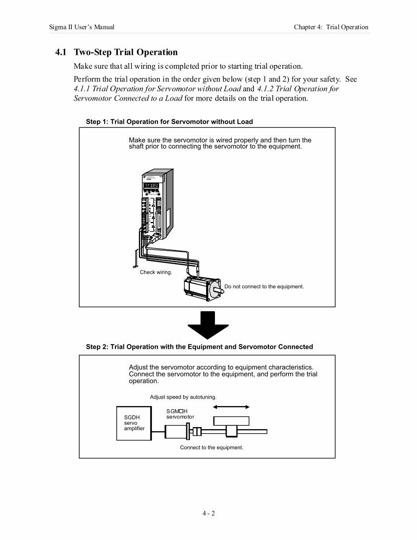
Sigma II User’s Manual Chapter 4: Trial Operation
4 - 2
4.1 Two-Step Trial OperationMake sure that all wiring is completed prior to starting trial operation. Perform the trial operation in the order given below (step 1 and 2) for your safety. See 4.1.1 Trial Operation for Servomotor without Load and 4.1.2 Trial Operation for Servomotor Connected to a Load for more details on the trial operation.
Make sure the servomotor is wired properly and then turn the shaft prior to connecting the servomotor to the equipment.
Check wiring.
CN3
CN1
L1CL2C
B1B2
U
V
W
L1
L2
1
2
CN2
SGDM-
MODE/SET DATA/CHARGE POWER
SERVOPACK200VYASKAWA
Do not connect to the equipment.
Adjust the servomotor according to equipment characteristics. Connect the servomotor to the equipment, and perform the trial operation.
SGDH servo amplifier
Connect to the equipment.
Adjust speed by autotuning.
Step 1: Trial Operation for Servomotor without Load
Step 2: Trial Operation with the Equipment and Servomotor Connected
SGM Hservomotor
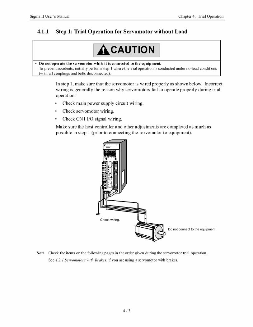
Sigma II User’s Manual Chapter 4: Trial Operation
4 - 3
4.1.1 Step 1: Trial Operation for Servomotor without Load
In step 1, make sure that the servomotor is wired properly as shown below. Incorrect wiring is generally the reason why servomotors fail to operate properly during trial operation.• Check main power supply circuit wiring.• Check servomotor wiring.• Check CN1 I/O signal wiring.Make sure the host controller and other adjustments are completed as much as possible in step 1 (prior to connecting the servomotor to equipment).
Note Check the items on the following pages in the order given during the servomotor trial operation.
See 4.2.1 Servomotors with Brakes, if you are using a servomotor with brakes.
• Do not operate the servomotor while it is connected to the equipment. To prevent accidents, initially perform step 1 where the trial operation is conducted under no-load conditions (with all couplings and belts disconnected).
CAUTION
CN3
CN1L1C
L2CB1B2
U
V
W
L1
L2
1
2
CN2
SGDH-
MODE/SET DATA/
CHARGE POWER
SERVOPACK200VYASKAWA
Check wiring.
Do not connect to the equipment.
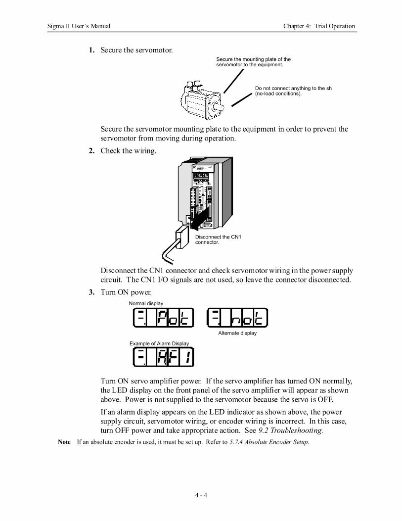
Sigma II User’s Manual Chapter 4: Trial Operation
4 - 4
1. Secure the servomotor.
Secure the servomotor mounting plate to the equipment in order to prevent the servomotor from moving during operation.
2. Check the wiring.
Disconnect the CN1 connector and check servomotor wiring in the power supply circuit. The CN1 I/O signals are not used, so leave the connector disconnected.
3. Turn ON power.
Turn ON servo amplifier power. If the servo amplifier has turned ON normally, the LED display on the front panel of the servo amplifier will appear as shown above. Power is not supplied to the servomotor because the servo is OFF.If an alarm display appears on the LED indicator as shown above, the power supply circuit, servomotor wiring, or encoder wiring is incorrect. In this case, turn OFF power and take appropriate action. See 9.2 Troubleshooting.
Note If an absolute encoder is used, it must be set up. Refer to 5.7.4 Absolute Encoder Setup.
Secure the mounting plate of the servomotor to the equipment.
Do not connect anything to the sha(no-load conditions).
Disconnect the CN1 connector.
L1
L2
L3
UVW
L1CL2CB1B2B3
12
CN3
CN1
CN2
YASKAWASERVOPACK
MODE/SET DATA/CHARGE POWER
SGDH-
200V
Normal display
Alternate display
Example of Alarm Display
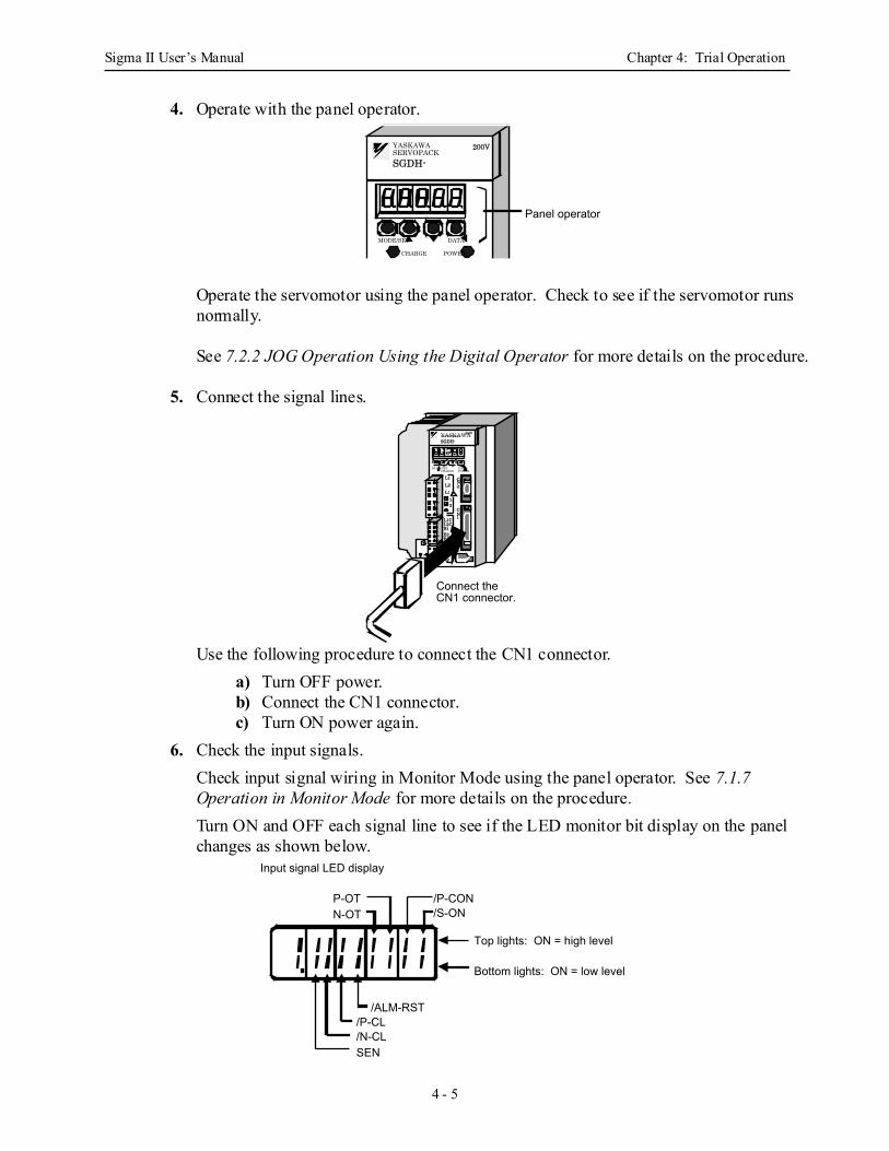
Sigma II User’s Manual Chapter 4: Trial Operation
4 - 5
4. Operate with the panel operator.
Operate the servomotor using the panel operator. Check to see if the servomotor runs normally.
See 7.2.2 JOG Operation Using the Digital Operator for more details on the procedure.
5. Connect the signal lines.
Use the following procedure to connect the CN1 connector.a) Turn OFF power.b) Connect the CN1 connector.c) Turn ON power again.
6. Check the input signals.Check input signal wiring in Monitor Mode using the panel operator. See 7.1.7 Operation in Monitor Mode for more details on the procedure.Turn ON and OFF each signal line to see if the LED monitor bit display on the panel changes as shown below.
SGDH-
MODE/SET DATA/
CHARGE POWER
SERVOPACK200VYASKAWA
Panel operator
Connect the CN1 connector.
L1L2L3
UVW
L1CL2CB1B2B3
12
CN3
CN1
CN2
YASKAWASERVOPACK
MODE/SET DATA/CHARGE POWER
SGDH-
200V
Input signal LED display
/P-CL/N-CL
Top lights: ON = high level
Bottom lights: ON = low level
/ALM-RST
/P-CON/S-ON
P-OTN-OT
SEN
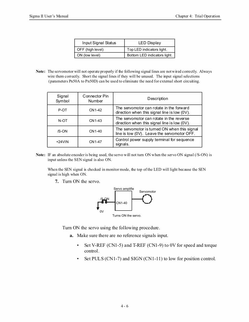
Sigma II User’s Manual Chapter 4: Trial Operation
4 - 6
Note: The servomotor will not operate properly if the following signal lines are not wired correctly. Always wire them correctly. Short the signal lines if they will be unused. The input signal selections (parameters Pn50A to Pn50D) can be used to eliminate the need for external short circuiting.
Note: IF an absolute encoder is being used, the servo will not turn ON when the servo ON signal (/S-ON) is input unless the SEN signal is also ON.
When the SEN signal is checked in monitor mode, the top of the LED will light because the SEN signal is high when ON.
7. Turn ON the servo.
Turn ON the servo using the following procedure.a. Make sure there are no reference signals input.
• Set V-REF (CN1-5) and T-REF (CN1-9) to 0V for speed and torque control.
• Set PULS (CN1-7) and SIGN (CN1-11) to low for position control.
Input Signal Status LED DisplayOFF (high level) Top LED indicators light.ON (low level) Bottom LED indicators light.
Signal Symbol
Connector Pin Number Description
P-OT CN1-42 The servomotor can rotate in the forward direction when this signal line is low (0V).
N-OT CN1-43 The servomotor can rotate in the reverse direction when this signal line is low (0V).
/S-ON CN1-40 The servomotor is turned ON when this signal line is low (0V). Leave the servomotor OFF.
+24VIN CN1-47 Control power supply terminal for sequence signals.
Servo amplifieServomotor
Turns ON the servo.0V
/S-ONCN1-40
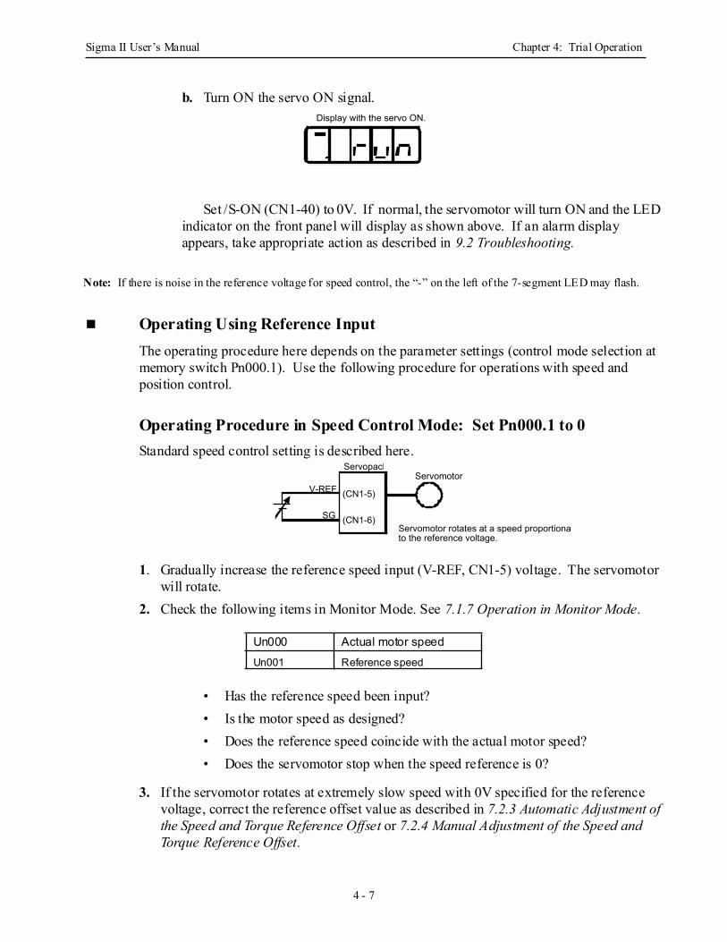
Sigma II User’s Manual Chapter 4: Trial Operation
4 - 7
b. Turn ON the servo ON signal.
Set /S-ON (CN1-40) to 0V. If normal, the servomotor will turn ON and the LED indicator on the front panel will display as shown above. If an alarm display appears, take appropriate action as described in 9.2 Troubleshooting.
Note: If there is noise in the reference voltage for speed control, the “-” on the left of the 7-segment LED may flash.
Operating Using Reference Input The operating procedure here depends on the parameter settings (control mode selection at memory switch Pn000.1). Use the following procedure for operations with speed and position control.
Operating Procedure in Speed Control Mode: Set Pn000.1 to 0 Standard speed control setting is described here.
1. Gradually increase the reference speed input (V-REF, CN1-5) voltage. The servomotor will rotate.
2. Check the following items in Monitor Mode. See 7.1.7 Operation in Monitor Mode.
• Has the reference speed been input?• Is the motor speed as designed?• Does the reference speed coincide with the actual motor speed?• Does the servomotor stop when the speed reference is 0?
3. If the servomotor rotates at extremely slow speed with 0V specified for the reference voltage, correct the reference offset value as described in 7.2.3 Automatic Adjustment of the Speed and Torque Reference Offset or 7.2.4 Manual Adjustment of the Speed and Torque Reference Offset.
Un000 Actual motor speedUn001 Reference speed
Display with the servo ON.
(CN1-5)
(CN1-6)
V-REF
Servomotor rotates at a speed proportionalto the reference voltage.
SG
ServopackServomotor
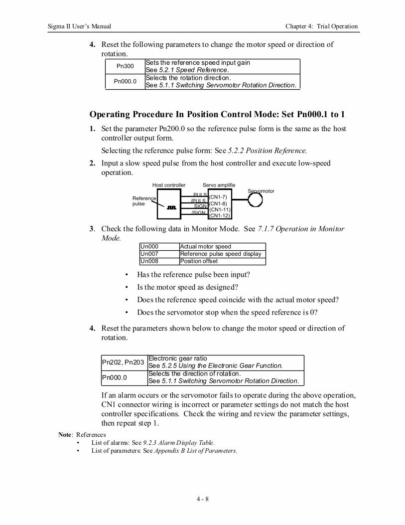
Sigma II User’s Manual Chapter 4: Trial Operation
4 - 8
4. Reset the following parameters to change the motor speed or direction of rotation.
Operating Procedure In Position Control Mode: Set Pn000.1 to 11. Set the parameter Pn200.0 so the reference pulse form is the same as the host
controller output form.Selecting the reference pulse form: See 5.2.2 Position Reference.
2. Input a slow speed pulse from the host controller and execute low-speed operation.
3. Check the following data in Monitor Mode. See 7.1.7 Operation in Monitor Mode.
• Has the reference pulse been input?• Is the motor speed as designed?• Does the reference speed coincide with the actual motor speed?• Does the servomotor stop when the speed reference is 0?
4. Reset the parameters shown below to change the motor speed or direction of rotation.
If an alarm occurs or the servomotor fails to operate during the above operation, CN1 connector wiring is incorrect or parameter settings do not match the host controller specifications. Check the wiring and review the parameter settings, then repeat step 1.
Note: References• List of alarms: See 9.2.3 Alarm Display Table.• List of parameters: See Appendix B List of Parameters.
Pn300 Sets the reference speed input gainSee 5.2.1 Speed Reference.
Pn000.0 Selects the rotation direction.See 5.1.1 Switching Servomotor Rotation Direction.
Un000 Actual motor speedUn007 Reference pulse speed displayUn008 Position offset
Pn202, Pn203 Electronic gear ratioSee 5.2.5 Using the Electronic Gear Function.
Pn000.0 Selects the direction of rotation.See 5.1.1 Switching Servomotor Rotation Direction.
PULS
Host controller
Reference pulse /PULS
SIGN/SIGN
(CN1-7)(CN1-8)(CN1-11)(CN1-12)
Servo amplifierServomotor
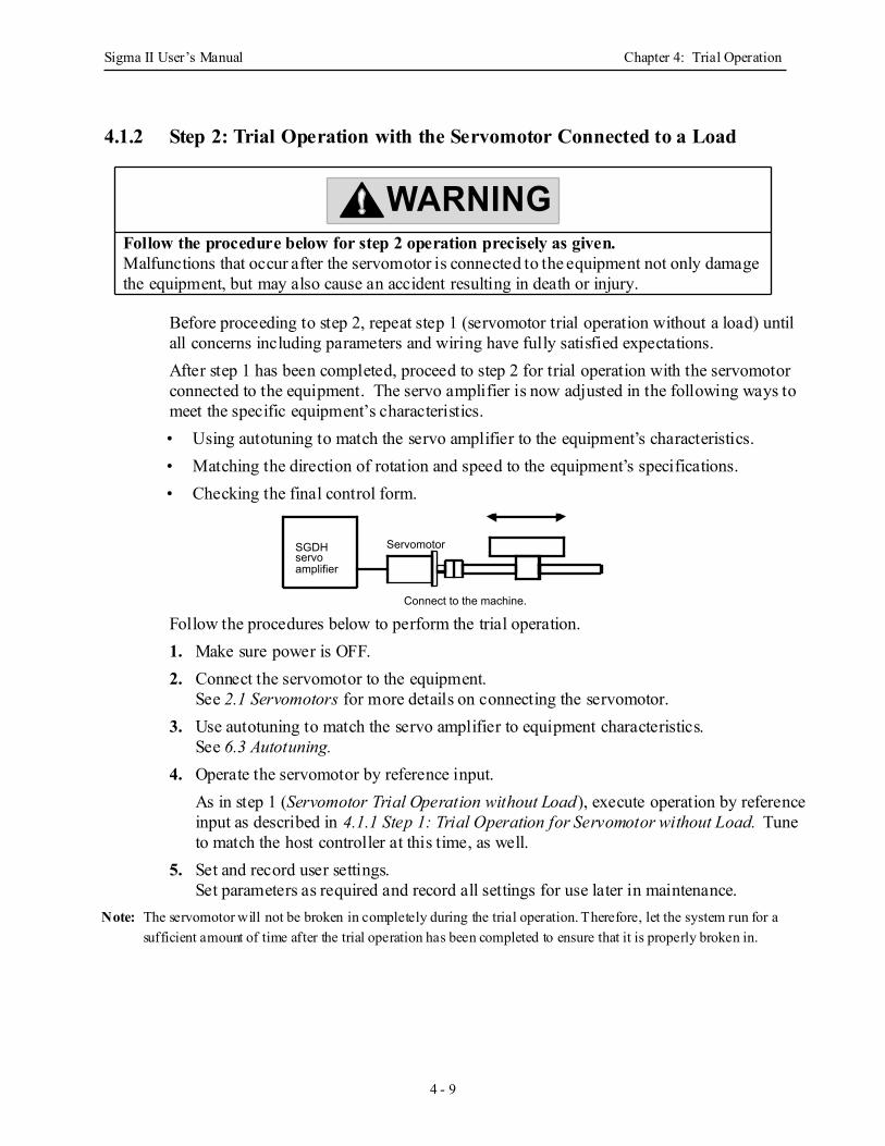
Sigma II User’s Manual Chapter 4: Trial Operation
4 - 9
4.1.2 Step 2: Trial Operation with the Servomotor Connected to a Load
Before proceeding to step 2, repeat step 1 (servomotor trial operation without a load) until all concerns including parameters and wiring have fully satisfied expectations.After step 1 has been completed, proceed to step 2 for trial operation with the servomotor connected to the equipment. The servo amplifier is now adjusted in the following ways to meet the specific equipment’s characteristics.• Using autotuning to match the servo amplifier to the equipment’s characteristics.• Matching the direction of rotation and speed to the equipment’s specifications.• Checking the final control form.
Follow the procedures below to perform the trial operation.1. Make sure power is OFF.2. Connect the servomotor to the equipment.
See 2.1 Servomotors for more details on connecting the servomotor.3. Use autotuning to match the servo amplifier to equipment characteristics.
See 6.3 Autotuning.4. Operate the servomotor by reference input.
As in step 1 (Servomotor Trial Operation without Load), execute operation by reference input as described in 4.1.1 Step 1: Trial Operation for Servomotor without Load. Tune to match the host controller at this time, as well.
5. Set and record user settings.Set parameters as required and record all settings for use later in maintenance.
Note: The servomotor will not be broken in completely during the trial operation. Therefore, let the system run for a sufficient amount of time after the trial operation has been completed to ensure that it is properly broken in.
Follow the procedure below for step 2 operation precisely as given.Malfunctions that occur after the servomotor is connected to the equipment not only damage the equipment, but may also cause an accident resulting in death or injury.
WARNING
SGDHservo amplifier
Servomotor
Connect to the machine.
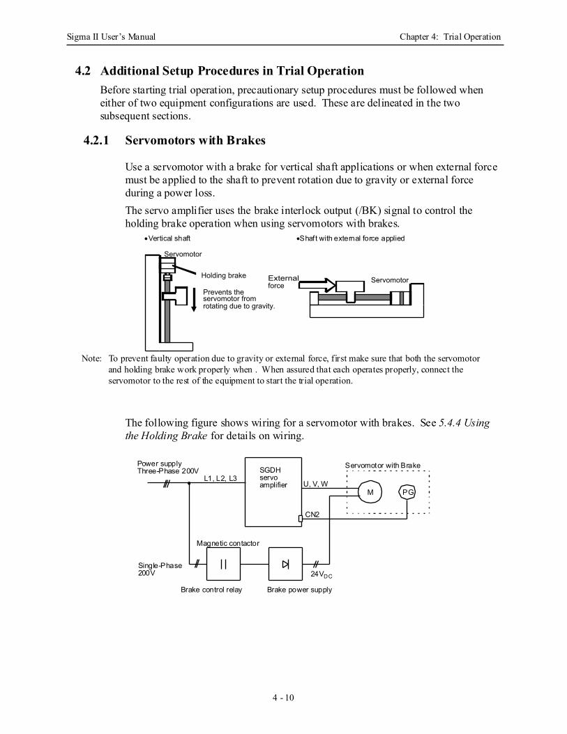
Sigma II User’s Manual Chapter 4: Trial Operation
4 - 10
4.2 Additional Setup Procedures in Trial OperationBefore starting trial operation, precautionary setup procedures must be followed when either of two equipment configurations are used. These are delineated in the two subsequent sections.
4.2.1 Servomotors with Brakes
Use a servomotor with a brake for vertical shaft applications or when external force must be applied to the shaft to prevent rotation due to gravity or external force during a power loss.The servo amplifier uses the brake interlock output (/BK) signal to control the holding brake operation when using servomotors with brakes.
Note: To prevent faulty operation due to gravity or external force, first make sure that both the servomotor and holding brake work properly when . When assured that each operates properly, connect the servomotor to the rest of the equipment to start the trial operation.
The following figure shows wiring for a servomotor with brakes. See 5.4.4 Using the Holding Brake for details on wiring.
Holding brake
Prevents the servomotor from rotating due to gravity.
External force
Servomotor
Servomotor
•Vertical shaft •Shaft with external force applied
Power supplyThree-Phase 200V
L1, L2, L3
Magnetic contactor
Single-Phase24VDC
CN2
U, V, W
Servomotor with Brake
200V
Brake power supply
SGDHservoamplifier
Brake control relay
M PG
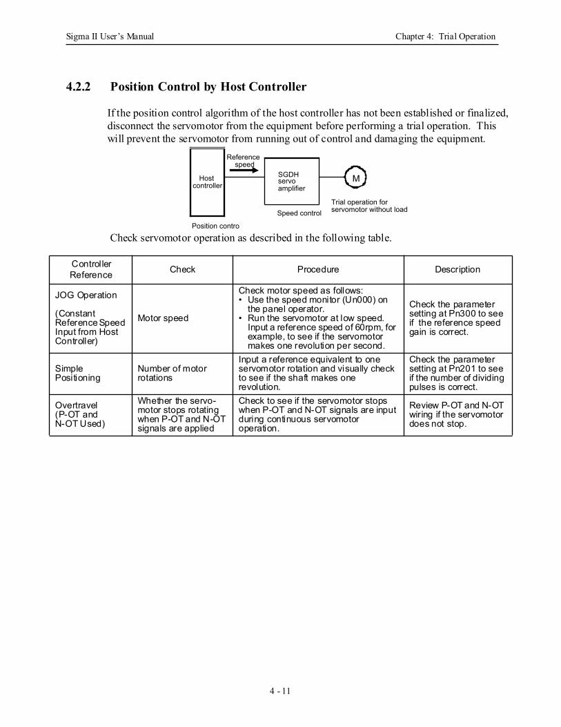
Sigma II User’s Manual Chapter 4: Trial Operation
4 - 11
4.2.2 Position Control by Host Controller
If the position control algorithm of the host controller has not been established or finalized, disconnect the servomotor from the equipment before performing a trial operation. This will prevent the servomotor from running out of control and damaging the equipment.
Check servomotor operation as described in the following table.
Controller Reference Check Procedure Description
JOG Operation
(ConstantReference Speed Input from Host Controller)
Motor speed
Check motor speed as follows:• Use the speed monitor (Un000) on
the panel operator.• Run the servomotor at low speed.
Input a reference speed of 60rpm, for example, to see if the servomotor makes one revolution per second.
Check the parameter setting at Pn300 to see if the reference speed gain is correct.
SimplePositioning
Number of motorrotations
Input a reference equivalent to one servomotor rotation and visually check to see if the shaft makes one revolution.
Check the parameter setting at Pn201 to see if the number of dividing pulses is correct.
Overtravel (P-OT andN-OT Used)
Whether the servo-motor stops rotating when P-OT and N-OT signals are applied
Check to see if the servomotor stops when P-OT and N-OT signals are input during continuous servomotor operation.
Review P-OT and N-OT wiring if the servomotor does not stop.
Trial operation for servomotor without load
MHost controller
Position contro
Speed control
Reference speed
SGDHservo amplifier
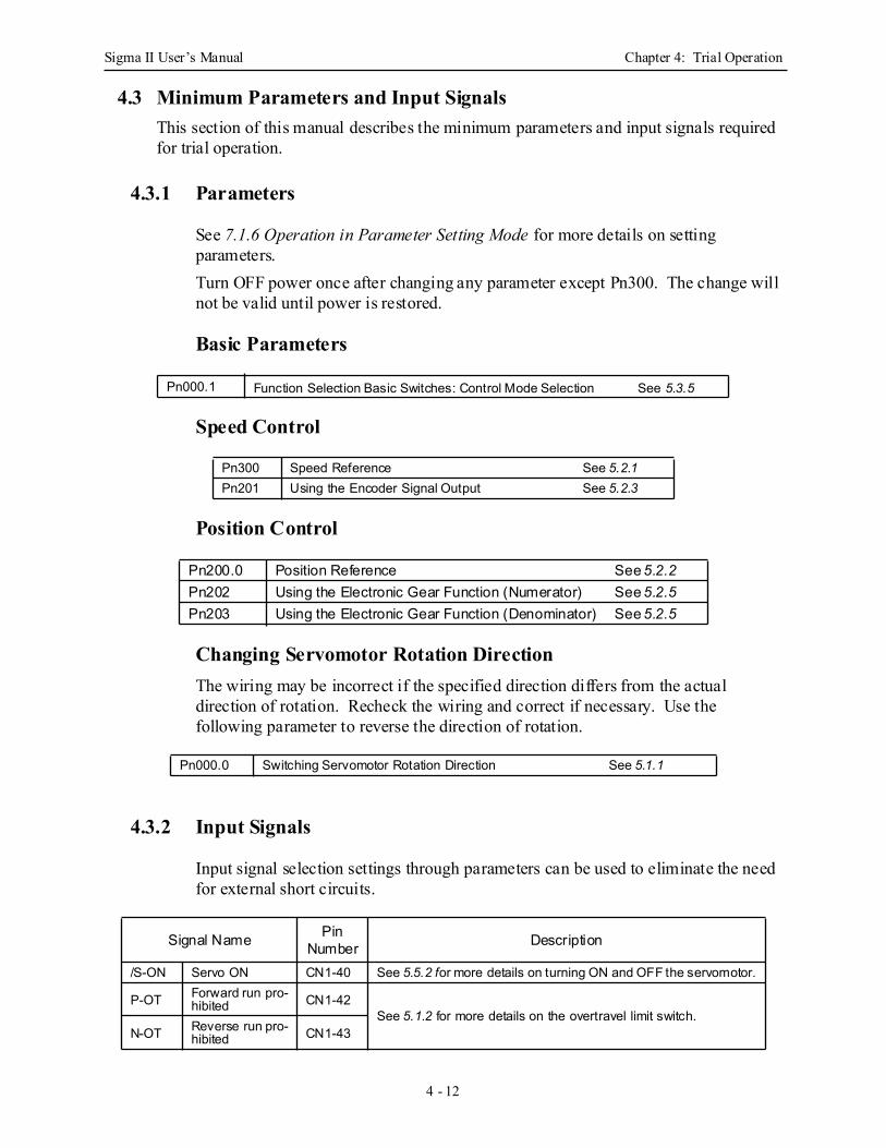
Sigma II User’s Manual Chapter 4: Trial Operation
4 - 12
4.3 Minimum Parameters and Input SignalsThis section of this manual describes the minimum parameters and input signals required for trial operation.
4.3.1 Parameters
See 7.1.6 Operation in Parameter Setting Mode for more details on setting parameters.Turn OFF power once after changing any parameter except Pn300. The change will not be valid until power is restored.
Basic Parameters
Speed Control
Position Control
Changing Servomotor Rotation DirectionThe wiring may be incorrect if the specified direction differs from the actual direction of rotation. Recheck the wiring and correct if necessary. Use the following parameter to reverse the direction of rotation.
4.3.2 Input Signals
Input signal selection settings through parameters can be used to eliminate the need for external short circuits.
Pn000.1 Function Selection Basic Switches: Control Mode Selection See 5.3.5
Pn300 Speed Reference See 5.2.1Pn201 Using the Encoder Signal Output See 5.2.3
Pn200.0 Position Reference See 5.2.2Pn202 Using the Electronic Gear Function (Numerator) See 5.2.5Pn203 Using the Electronic Gear Function (Denominator) See 5.2.5
Pn000.0 Switching Servomotor Rotation Direction See 5.1.1
Signal Name Pin Number Description
/S-ON Servo ON CN1-40 See 5.5.2 for more details on turning ON and OFF the servomotor.
P-OT Forward run pro-hibited CN1-42
See 5.1.2 for more details on the overtravel limit switch.N-OT Reverse run pro-
hibited CN1-43
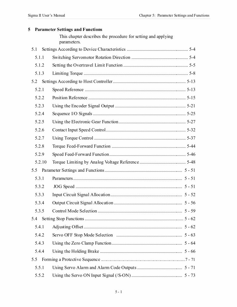
Sigma II User’s Manual Chapter 5: Parameter Settings and Functions
5 - 1
5 Parameter Settings and FunctionsThis chapter describes the procedure for setting and applying parameters.
5.1 Settings According to Device Characteristics ..................................................... 5-4
5.1.1 Switching Servomotor Rotation Direction ................................................. 5-4
5.1.2 Setting the Overtravel Limit Function ........................................................ 5-5
5.1.3 Limiting Torque .......................................................................................... 5-8
5.2 Settings According to Host Controller............................................................... 5-13
5.2.1 Speed Reference ....................................................................................... 5-13
5.2.2 Position Reference .................................................................................... 5-15
5.2.3 Using the Encoder Signal Output ............................................................. 5-21
5.2.4 Sequence I/O Signals ................................................................................ 5-25
5.2.5 Using the Electronic Gear Function.......................................................... 5-27
5.2.6 Contact Input Speed Control..................................................................... 5-32
5.2.7 Using Torque Control ............................................................................... 5-37
5.2.8 Torque Feed-Forward Function ................................................................ 5-44
5.2.9 Speed Feed-Forward Function.................................................................. 5-46
5.2.10 Torque Limiting by Analog Voltage Reference ........................................ 5-48
5.5 Parameter Settings and Functions ................................................................... 5 - 51
5.3.1 Parameters .............................................................................................. 5 - 51
5.3.2 JOG Speed ............................................................................................ 5 - 51
5.3.3 Input Circuit Signal Allocation.............................................................. 5 - 52
5.3.4 Output Circuit Signal Allocation ........................................................... 5 - 56
5.3.5 Control Mode Selection ......................................................................... 5 - 59
5.4 Setting Stop Functions ..................................................................................... 5 - 62
5.4.1 Adjusting Offset ..................................................................................... 5 - 62
5.4.2 Servo OFF Stop Mode Selection ......................................................... 5 - 63
5.4.3 Using the Zero Clamp Function............................................................. 5 - 64
5.4.4 Using the Holding Brake ....................................................................... 5 - 66
5.5 Forming a Protective Sequence ...............................................................................7 - 71
5.5.1 Using Servo Alarm and Alarm Code Outputs ....................................... 5 - 71
5.5.2 Using the Servo ON Input Signal (/S-ON) ............................................ 5 - 73
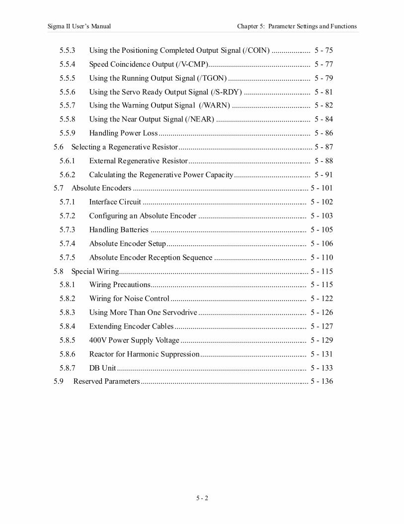
Sigma II User’s Manual Chapter 5: Parameter Settings and Functions
5 - 2
5.5.3 Using the Positioning Completed Output Signal (/COIN) .................... 5 - 75
5.5.4 Speed Coincidence Output (/V-CMP).................................................... 5 - 77
5.5.5 Using the Running Output Signal (/TGON) .......................................... 5 - 79
5.5.6 Using the Servo Ready Output Signal (/S-RDY) .................................. 5 - 81
5.5.7 Using the Warning Output Signal (/WARN) ........................................ 5 - 82
5.5.8 Using the Near Output Signal (/NEAR) ................................................ 5 - 84
5.5.9 Handling Power Loss ............................................................................. 5 - 86
5.6 Selecting a Regenerative Resistor.................................................................... 5 - 87
5.6.1 External Regenerative Resistor.............................................................. 5 - 88
5.6.2 Calculating the Regenerative Power Capacity....................................... 5 - 91
5.7 Absolute Encoders ......................................................................................... 5 - 101
5.7.1 Interface Circuit ................................................................................... 5 - 102
5.7.2 Configuring an Absolute Encoder ....................................................... 5 - 103
5.7.3 Handling Batteries ............................................................................... 5 - 105
5.7.4 Absolute Encoder Setup....................................................................... 5 - 106
5.7.5 Absolute Encoder Reception Sequence ............................................... 5 - 110
5.8 Special Wiring................................................................................................ 5 - 115
5.8.1 Wiring Precautions............................................................................... 5 - 115
5.8.2 Wiring for Noise Control ..................................................................... 5 - 122
5.8.3 Using More Than One Servodrive ....................................................... 5 - 126
5.8.4 Extending Encoder Cables ................................................................... 5 - 127
5.8.5 400V Power Supply Voltage ................................................................ 5 - 129
5.8.6 Reactor for Harmonic Suppression...................................................... 5 - 131
5.8.7 DB Unit ................................................................................................ 5 - 133
5.9 Reserved Parameters ..................................................................................... 5 - 136
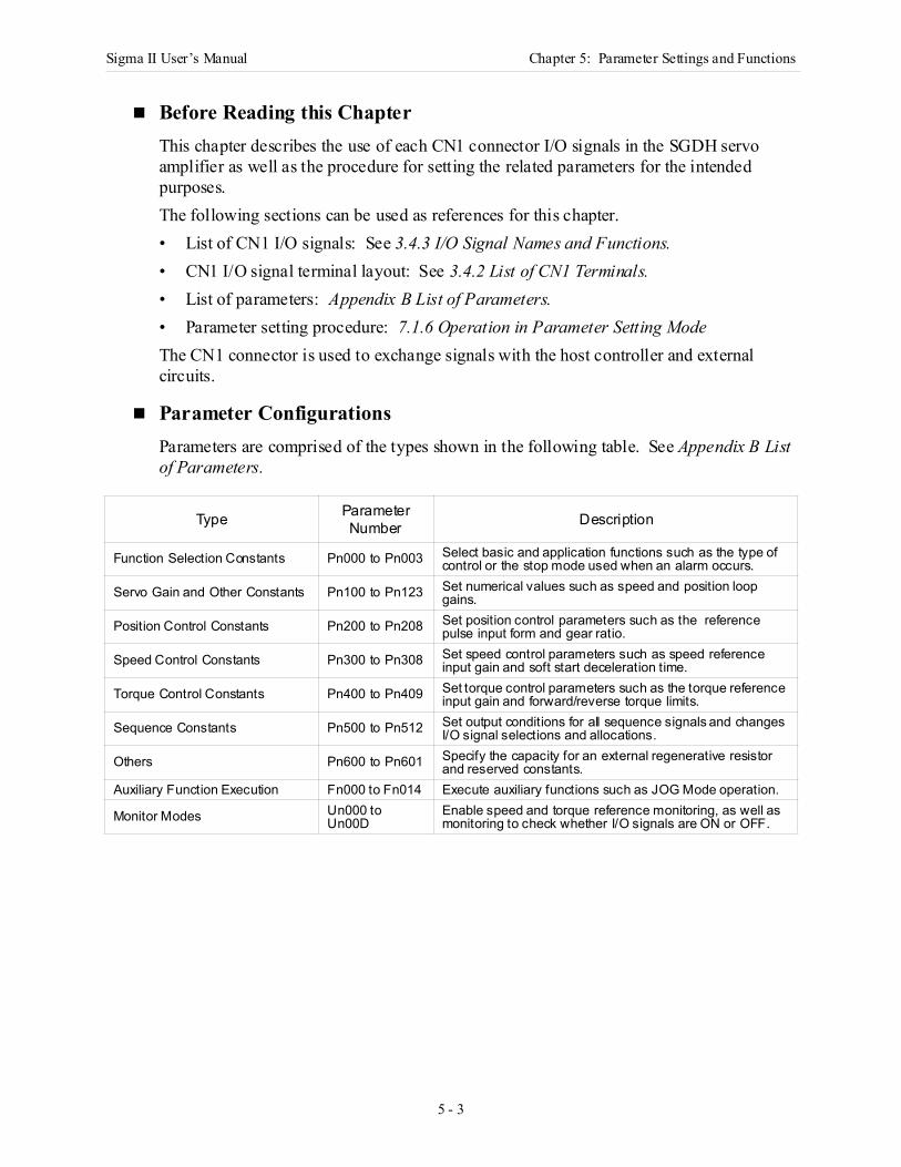
Sigma II User’s Manual Chapter 5: Parameter Settings and Functions
5 - 3
Before Reading this ChapterThis chapter describes the use of each CN1 connector I/O signals in the SGDH servo amplifier as well as the procedure for setting the related parameters for the intended purposes. The following sections can be used as references for this chapter.• List of CN1 I/O signals: See 3.4.3 I/O Signal Names and Functions.• CN1 I/O signal terminal layout: See 3.4.2 List of CN1 Terminals.• List of parameters: Appendix B List of Parameters.• Parameter setting procedure: 7.1.6 Operation in Parameter Setting ModeThe CN1 connector is used to exchange signals with the host controller and external circuits.
Parameter Configurations Parameters are comprised of the types shown in the following table. See Appendix B List of Parameters.
Type Parameter Number Description
Function Selection Constants Pn000 to Pn003 Select basic and application functions such as the type of control or the stop mode used when an alarm occurs.
Servo Gain and Other Constants Pn100 to Pn123 Set numerical values such as speed and position loop gains.
Position Control Constants Pn200 to Pn208 Set position control parameters such as the reference pulse input form and gear ratio.
Speed Control Constants Pn300 to Pn308 Set speed control parameters such as speed reference input gain and soft start deceleration time.
Torque Control Constants Pn400 to Pn409 Set torque control parameters such as the torque reference input gain and forward/reverse torque limits.
Sequence Constants Pn500 to Pn512 Set output conditions for all sequence signals and changes I/O signal selections and allocations.
Others Pn600 to Pn601 Specify the capacity for an external regenerative resistor and reserved constants.
Auxiliary Function Execution Fn000 to Fn014 Execute auxiliary functions such as JOG Mode operation.
Monitor Modes Un000 to Un00D
Enable speed and torque reference monitoring, as well as monitoring to check whether I/O signals are ON or OFF.
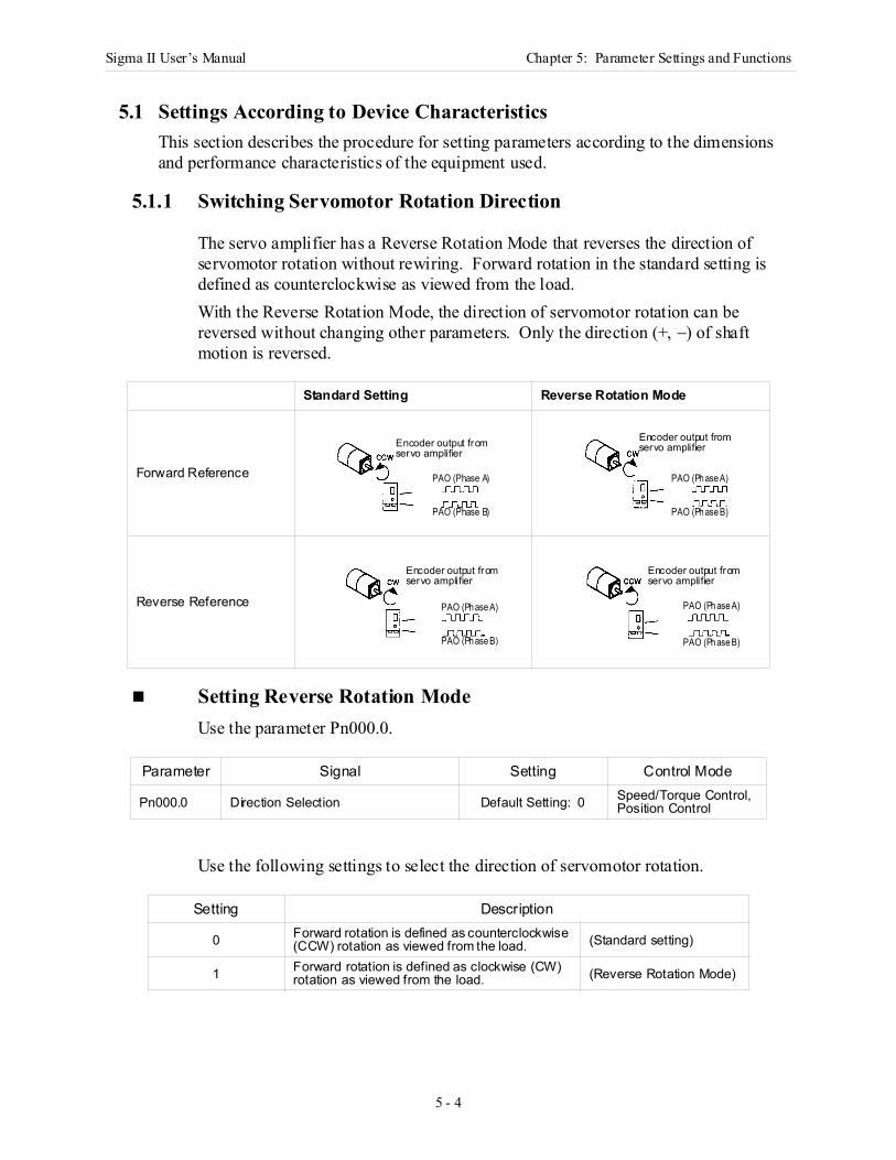
Sigma II User’s Manual Chapter 5: Parameter Settings and Functions
5 - 4
5.1 Settings According to Device CharacteristicsThis section describes the procedure for setting parameters according to the dimensions and performance characteristics of the equipment used.
5.1.1 Switching Servomotor Rotation Direction
The servo amplifier has a Reverse Rotation Mode that reverses the direction of servomotor rotation without rewiring. Forward rotation in the standard setting is defined as counterclockwise as viewed from the load. With the Reverse Rotation Mode, the direction of servomotor rotation can be reversed without changing other parameters. Only the direction (+, −) of shaft motion is reversed.
Setting Reverse Rotation Mode Use the parameter Pn000.0.
Use the following settings to select the direction of servomotor rotation.
Standard Setting Reverse Rotation Mode
Forward Reference
Reverse Reference
Parameter Signal Setting Control Mode
Pn000.0 Direction Selection Default Setting: 0 Speed/Torque Control, Position Control
Setting Description
0 Forward rotation is defined as counterclockwise (CCW) rotation as viewed from the load. (Standard setting)
1 Forward rotation is defined as clockwise (CW) rotation as viewed from the load. (Reverse Rotation Mode)
Encoder output fromservo amplifier
PAO (Phase A)
PAO (Phase B)
Encoder output fromservo amplifier
PAO (Ph ase A)
PAO (Ph ase B)
Encoder output fromservo amplifier
PAO (Ph ase A)
PAO (Ph ase B)
Encoder output fromservo amplifier
PAO (Ph ase A)
PAO (Ph ase B)
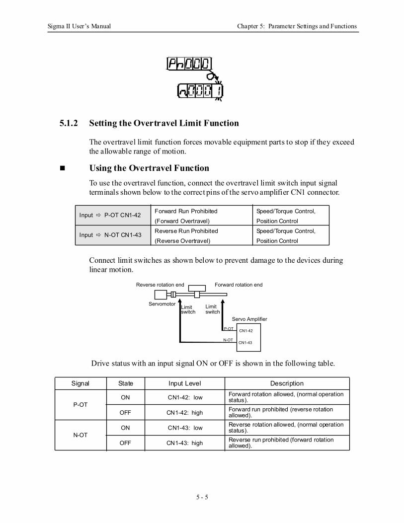
Sigma II User’s Manual Chapter 5: Parameter Settings and Functions
5 - 5
5.1.2 Setting the Overtravel Limit Function
The overtravel limit function forces movable equipment parts to stop if they exceed the allowable range of motion.
Using the Overtravel Function To use the overtravel function, connect the overtravel limit switch input signal terminals shown below to the correct pins of the servo amplifier CN1 connector.
Connect limit switches as shown below to prevent damage to the devices during linear motion.
Drive status with an input signal ON or OFF is shown in the following table.
Input P-OT CN1-42 Forward Run Prohibited(Forward Overtravel)
Speed/Torque Control, Position Control
Input N-OT CN1-43 Reverse Run Prohibited(Reverse Overtravel)
Speed/Torque Control, Position Control
Signal State Input Level Description
P-OTON CN1-42: low Forward rotation allowed, (normal operation
status).
OFF CN1-42: high Forward run prohibited (reverse rotation allowed).
N-OTON CN1-43: low Reverse rotation allowed, (normal operation
status).
OFF CN1-43: high Reverse run prohibited (forward rotation allowed).
Forward rotation endReverse rotation end
Limit switch
Servomotor
Servo Amplifier
CN1-42
CN1-43N-OT
P-OT
Limit switch
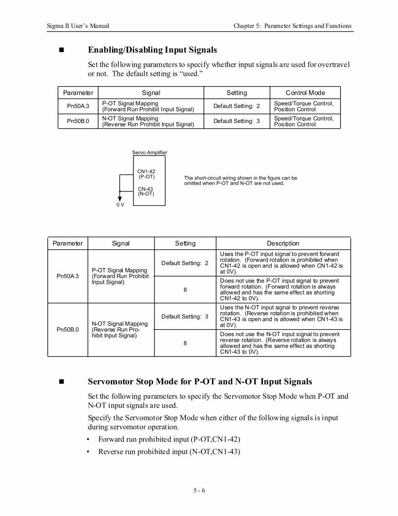
Sigma II User’s Manual Chapter 5: Parameter Settings and Functions
5 - 6
Enabling/Disabling Input Signals Set the following parameters to specify whether input signals are used for overtravel or not. The default setting is “used.”
Servomotor Stop Mode for P-OT and N-OT Input Signals Set the following parameters to specify the Servomotor Stop Mode when P-OT and N-OT input signals are used. Specify the Servomotor Stop Mode when either of the following signals is input during servomotor operation.• Forward run prohibited input (P-OT,CN1-42)• Reverse run prohibited input (N-OT,CN1-43)
Parameter Signal Setting Control Mode
Pn50A.3 P-OT Signal Mapping(Forward Run Prohibit Input Signal) Default Setting: 2 Speed/Torque Control,
Position Control
Pn50B.0 N-OT Signal Mapping(Reverse Run Prohibit Input Signal) Default Setting: 3 Speed/Torque Control,
Position Control
Parameter Signal Setting Description
Pn50A.3P-OT Signal Mapping(Forward Run Prohibit Input Signal)
Default Setting: 2Uses the P-OT input signal to prevent forward rotation. (Forward rotation is prohibited when CN1-42 is open and is allowed when CN1-42 is at 0V).
8Does not use the P-OT input signal to prevent forward rotation. (Forward rotation is always allowed and has the same effect as shorting CN1-42 to 0V).
Pn50B.0N-OT Signal Mapping(Reverse Run Pro-hibit Input Signal)
Default Setting: 3Uses the N-OT input signal to prevent reverse rotation. (Reverse rotation is prohibited when CN1-43 is open and is allowed when CN1-43 is at 0V).
8Does not use the N-OT input signal to prevent reverse rotation. (Reverse rotation is always allowed and has the same effect as shorting CN1-43 to 0V).
CN1-42 (P-OT)
CN-43 (N-OT)
0 V
The short-circuit wiring shown in the figure can be omitted when P-OT and N-OT are not used.
Servo Amplifier
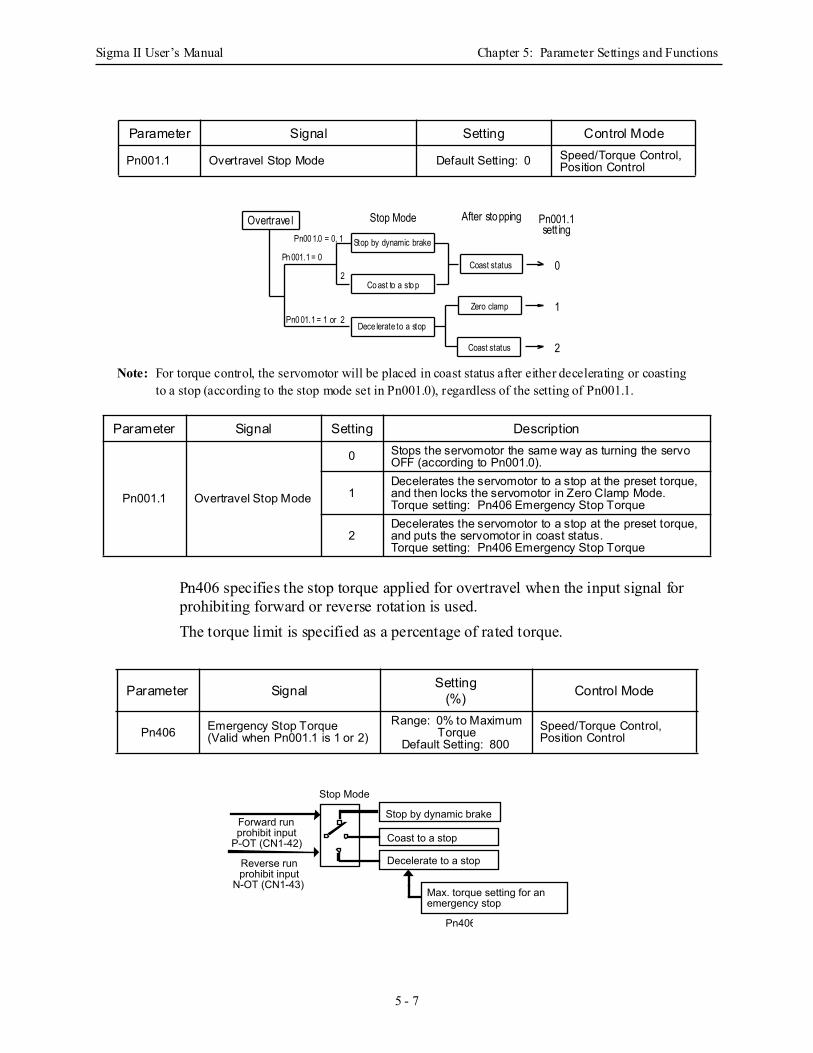
Sigma II User’s Manual Chapter 5: Parameter Settings and Functions
5 - 7
Note: For torque control, the servomotor will be placed in coast status after either decelerating or coasting to a stop (according to the stop mode set in Pn001.0), regardless of the setting of Pn001.1.
Pn406 specifies the stop torque applied for overtravel when the input signal for prohibiting forward or reverse rotation is used.The torque limit is specified as a percentage of rated torque.
Parameter Signal Setting Control Mode
Pn001.1 Overtravel Stop Mode Default Setting: 0 Speed/Torque Control, Position Control
Parameter Signal Setting Description
Pn001.1 Overtravel Stop Mode
0 Stops the servomotor the same way as turning the servo OFF (according to Pn001.0).
1Decelerates the servomotor to a stop at the preset torque, and then locks the servomotor in Zero Clamp Mode.Torque setting: Pn406 Emergency Stop Torque
2Decelerates the servomotor to a stop at the preset torque, and puts the servomotor in coast status.Torque setting: Pn406 Emergency Stop Torque
Parameter Signal Setting(%) Control Mode
Pn406 Emergency Stop Torque(Valid when Pn001.1 is 1 or 2)
Range: 0% to Maximum Torque
Default Setting: 800Speed/Torque Control, Position Control
Coast status
Zero clamp
Co ast to a sto p
Dece lerate to a stop
Stop by dynamic brake
Coast status
Overtrave l Stop ModePn00 1.0 = 0, 1
Pn 001.1 = 0
2
Pn0 01.1 = 1 or 2
After stopping Pn001.1sett ing
0
1
2
Max. torque setting for an emergency stop
Forward run prohibit input
P-OT (CN1-42)
Reverse run prohibit input
N-OT (CN1-43)
Stop Mode
Pn406
Stop by dynamic brake
Coast to a stop
Decelerate to a stop
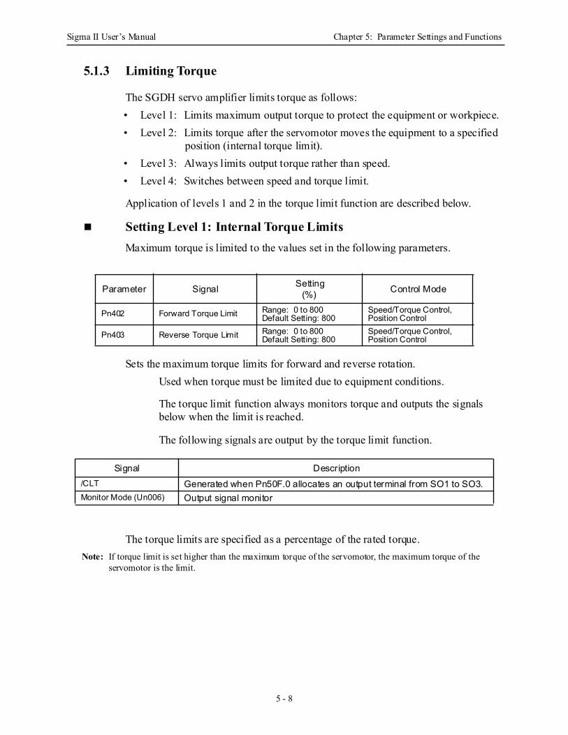
Sigma II User’s Manual Chapter 5: Parameter Settings and Functions
5 - 8
5.1.3 Limiting Torque
The SGDH servo amplifier limits torque as follows:• Level 1: Limits maximum output torque to protect the equipment or workpiece.• Level 2: Limits torque after the servomotor moves the equipment to a specified
position (internal torque limit).• Level 3: Always limits output torque rather than speed.• Level 4: Switches between speed and torque limit.
Application of levels 1 and 2 in the torque limit function are described below.
Setting Level 1: Internal Torque Limits Maximum torque is limited to the values set in the following parameters.
Sets the maximum torque limits for forward and reverse rotation.Used when torque must be limited due to equipment conditions.
The torque limit function always monitors torque and outputs the signals below when the limit is reached.
The following signals are output by the torque limit function.
The torque limits are specified as a percentage of the rated torque.Note: If torque limit is set higher than the maximum torque of the servomotor, the maximum torque of the
servomotor is the limit.
Parameter Signal Setting(%) Control Mode
Pn402 Forward Torque Limit Range: 0 to 800Default Setting: 800
Speed/Torque Control, Position Control
Pn403 Reverse Torque Limit Range: 0 to 800Default Setting: 800
Speed/Torque Control, Position Control
Signal Description/CLT Generated when Pn50F.0 allocates an output terminal from SO1 to SO3.Monitor Mode (Un006) Output signal monitor
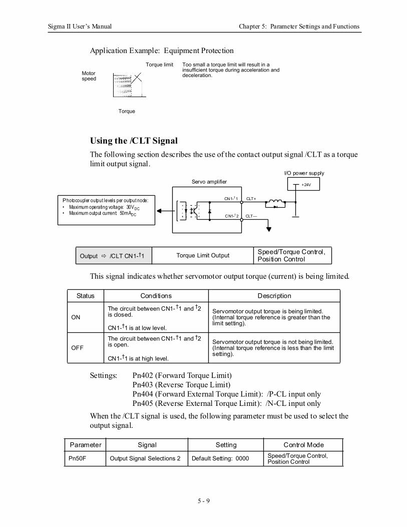
Sigma II User’s Manual Chapter 5: Parameter Settings and Functions
5 - 9
Application Example: Equipment Protection
Using the /CLT Signal The following section describes the use of the contact output signal /CLT as a torque limit output signal.
This signal indicates whether servomotor output torque (current) is being limited.
Settings: Pn402 (Forward Torque Limit) Pn403 (Reverse Torque Limit) Pn404 (Forward External Torque Limit): /P-CL input onlyPn405 (Reverse External Torque Limit): /N-CL input only
When the /CLT signal is used, the following parameter must be used to select the output signal.
Output /CLT CN1-†1 Torque Limit Output Speed/Torque Control, Position Control
Status Conditions Description
ONThe circuit between CN1-†1 and †2 is closed.
CN1-†1 is at low level.
Servomotor output torque is being limited.(Internal torque reference is greater than the limit setting).
OFFThe circuit between CN1-†1 and †2 is open.
CN1-†1 is at high level.
Servomotor output torque is not being limited.(Internal torque reference is less than the limit setting).
Parameter Signal Setting Control Mode
Pn50F Output Signal Selections 2 Default Setting: 0000 Speed/Torque Control, Position Control
Motor speed
Torque limit
Torque
Too small a torque limit will result in a insufficient torque during acceleration and deceleration.
Servo amplifier
CN1-† 1
CN1-† 2 CLT—
CLT+
I/O power supply
+24V
Photocoupler output levels per output node:• Maximum operating voltage: 30VDC• Maximum output current: 50mADC
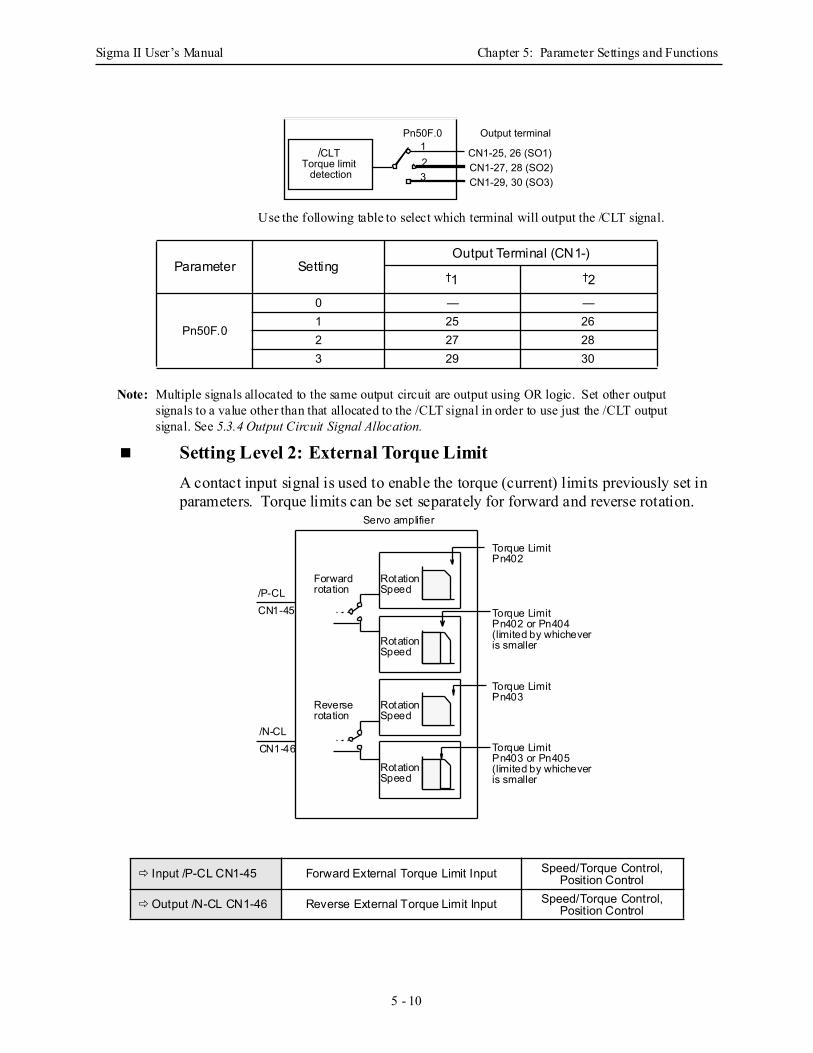
Sigma II User’s Manual Chapter 5: Parameter Settings and Functions
5 - 10
Use the following table to select which terminal will output the /CLT signal.
Note: Multiple signals allocated to the same output circuit are output using OR logic. Set other output signals to a value other than that allocated to the /CLT signal in order to use just the /CLT output signal. See 5.3.4 Output Circuit Signal Allocation.
Setting Level 2: External Torque Limit A contact input signal is used to enable the torque (current) limits previously set in parameters. Torque limits can be set separately for forward and reverse rotation.
Parameter SettingOutput Terminal (CN1-)
†1 †2
Pn50F.0
0 — —1 25 262 27 283 29 30
Input /P-CL CN1-45 Forward External Torque Limit Input Speed/Torque Control, Position Control
Output /N-CL CN1-46 Reverse External Torque Limit Input Speed/Torque Control, Position Control
Output terminal
CN1-25, 26 (SO1)CN1-27, 28 (SO2)CN1-29, 30 (SO3)
CLTTorque limit
detection 23
1Pn50F.0
/
RotationSpeed
RotationSpeed
RotationSpeed
RotationSpeed
Forwardrotation
rotationReverse
Torque Limit
Torque Limit
Torque Limit
Pn403
Pn403 or Pn405(limited by whicheveris smaller
Torque LimitPn402 or Pn404(limited by whicheveris smaller
Pn402
/P-CLCN1-45
/N-CLCN1-46
Servo amplifier
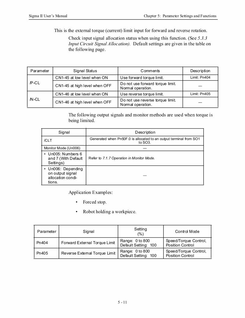
Sigma II User’s Manual Chapter 5: Parameter Settings and Functions
5 - 11
This is the external torque (current) limit input for forward and reverse rotation. Check input signal allocation status when using this function. (See 5.3.3 Input Circuit Signal Allocation). Default settings are given in the table on the following page.
The following output signals and monitor methods are used when torque is being limited.
Application Examples:
• Forced stop.
• Robot holding a workpiece.
Parameter Signal Status Comments Description
/P-CLCN1-45 at low level when ON Use forward torque limit. Limit: Pn404
CN1-45 at high level when OFF Do not use forward torque limit. Normal operation. —
/N-CLCN1-46 at low level when ON Use reverse torque limit. Limit: Pn405
CN1-46 at high level when OFF Do not use reverse torque limit. Normal operation. —
Signal Description
/CLT Generated when Pn50F.0 is allocated to an output terminal from SO1 to SO3.
Monitor Mode (Un006) —• Un005: Numbers 6
and 7 (With Default Settings)
Refer to 7.1.7 Operation in Monitor Mode.
• Un006: Depending on output signal allocation condi-tions.
—
Parameter Signal Setting(%) Control Mode
Pn404 Forward External Torque Limit Range: 0 to 800Default Setting: 100
Speed/Torque Control, Position Control
Pn405 Reverse External Torque Limit Range: 0 to 800Default Setting: 100
Speed/Torque Control, Position Control
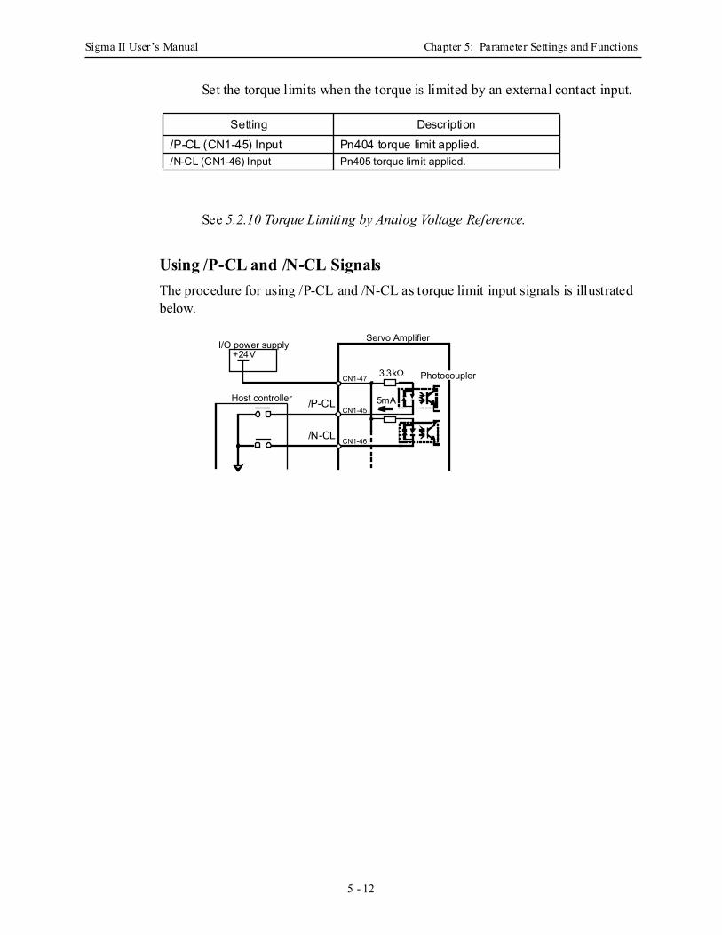
Sigma II User’s Manual Chapter 5: Parameter Settings and Functions
5 - 12
Set the torque limits when the torque is limited by an external contact input.
See 5.2.10 Torque Limiting by Analog Voltage Reference.
Using /P-CL and /N-CL Signals The procedure for using /P-CL and /N-CL as torque limit input signals is illustrated below.
Setting Description/P-CL (CN1-45) Input Pn404 torque limit applied. /N-CL (CN1-46) Input Pn405 torque limit applied.
I/O power supply Servo Amplifier
CN1-47
CN1-45
CN1-46
Host controller
Photocoupler
/P-CL
/N-CL
5mA
3.3kΩ
+24V
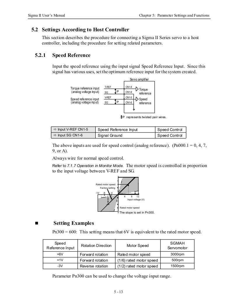
Sigma II User’s Manual Chapter 5: Parameter Settings and Functions
5 - 13
5.2 Settings According to Host ControllerThis section describes the procedure for connecting a Sigma II Series servo to a host controller, including the procedure for setting related parameters.
5.2.1 Speed Reference
Input the speed reference using the input signal Speed Reference Input. Since this signal has various uses, set the optimum reference input for the system created.
The above inputs are used for speed control (analog reference). (Pn000.1 = 0, 4, 7, 9, or A).Always wire for normal speed control. Refer to 7.1.7 Operation in Monitor Mode. The motor speed is controlled in proportion to the input voltage between V-REF and SG.
Setting Examples Pn300 = 600: This setting means that 6V is equivalent to the rated motor speed.
Parameter Pn300 can be used to change the voltage input range.
Input V-REF CN1-5 Speed Reference Input Speed Control Input SG CN1-6 Signal Ground Speed Control
Speed Reference Input Rotation Direction Motor Speed SGMAH
Servomotor+6V Forward rotation Rated motor speed 3000rpm+1V Forward rotation (1/6) rated motor speed 500rpm-3V Reverse rotation (1/2) rated motor speed 1500rpm
Torquerefe renceSpeedreference
CN1-9
CN1-9
CN1-5
CN1-6
SG
V-REF
SG
T-REF
Servo amplif ier
Torque reference input(analog voltage input)
Speed refe rence input(analog voltage input)
P represents twisted pair wires.
P
P
Input voltage (V)
-4-8-124 8 12
Factory settingRated motor speed
Rated motor speed
The slope is set in Pn300.

Sigma II User’s Manual Chapter 5: Parameter Settings and Functions
5 - 14
Input Circuit Example
• Always use twisted pair cable for noise control. Recommended variable resistor: Model 25HP-10B manufactured by Sakae Tsushin Kogyo Co., Ltd.
Connect V-REF and SG to the speed reference output terminals on the host controller when using a host controller, such as a programmable controller, for position control.
Adjust Pn300 according to the output voltage specifications of the host controller. Adjust the speed reference input adjustment factor at the following parameter.
Set the voltage range for the speed reference input V-REF at CN1-5 according to host controller and external circuit output range.
The default setting is adjusted so that a 6V input is equivalent to the rated motor speed of all applicable servomotors.
Note: The maximum allowable voltage to the speed reference input (between CN1-5 and 6) is ± 12VD C.
Parameter Signal Setting Control Mode
Pn300 Speed Reference Input Adjustment Factor
Range: 150 to 3000 x (0.01V/rated motor speed) Speed Control
Servo Amplifier
CN1-5
CN1-6P
+ 12V
470Ω, ½W minimum
2kΩVREF
SG
V-REF
SG
P AO/PAO
PBO/PBO
CN1-5
CN1-6
CN1-33
CN1-35
Speed
CN1-34
CN1-36
P represents twisted pair wires.
referenceoutputterminals
Feedbackpulse inputterminals
Host controller Servo amplifier
P
P
P
Reference speed (rpm)
Reference voltage (V)
Set this slope.
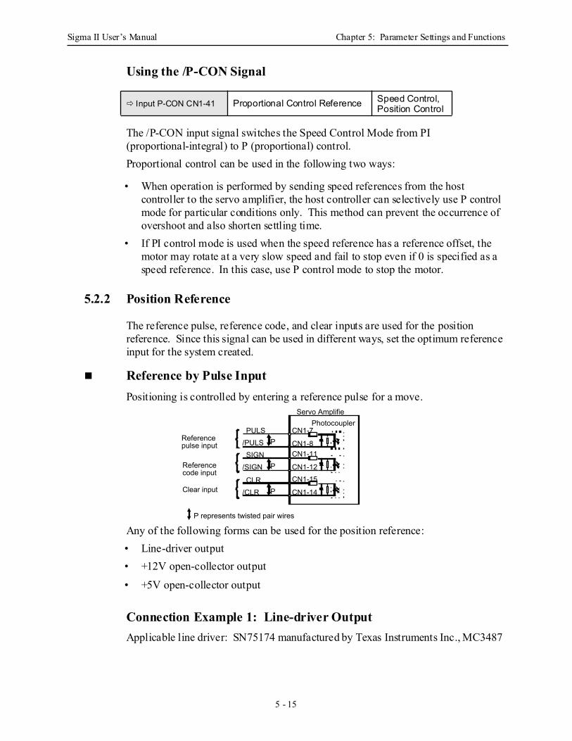
Sigma II User’s Manual Chapter 5: Parameter Settings and Functions
5 - 15
Using the /P-CON Signal
The /P-CON input signal switches the Speed Control Mode from PI (proportional-integral) to P (proportional) control.Proportional control can be used in the following two ways:
• When operation is performed by sending speed references from the host controller to the servo amplifier, the host controller can selectively use P control mode for particular conditions only. This method can prevent the occurrence of overshoot and also shorten settling time.
• If PI control mode is used when the speed reference has a reference offset, the motor may rotate at a very slow speed and fail to stop even if 0 is specified as a speed reference. In this case, use P control mode to stop the motor.
5.2.2 Position Reference
The reference pulse, reference code, and clear inputs are used for the position reference. Since this signal can be used in different ways, set the optimum reference input for the system created.
Reference by Pulse InputPositioning is controlled by entering a reference pulse for a move.
Any of the following forms can be used for the position reference: • Line-driver output • +12V open-collector output
• +5V open-collector output
Connection Example 1: Line-driver Output Applicable line driver: SN75174 manufactured by Texas Instruments Inc., MC3487
Input P-CON CN1-41 Proportional Control Reference Speed Control, Position Control
Reference code input
Clear input
Reference pulse input
PULS/PULS
CN1-7
CN1-8P
SIGN/SIGN
CN1-11
CN1-12P
CLR/CLR
CN1-15
CN1-14P
Servo AmplifiePhotocoupler
P represents twisted pair wires
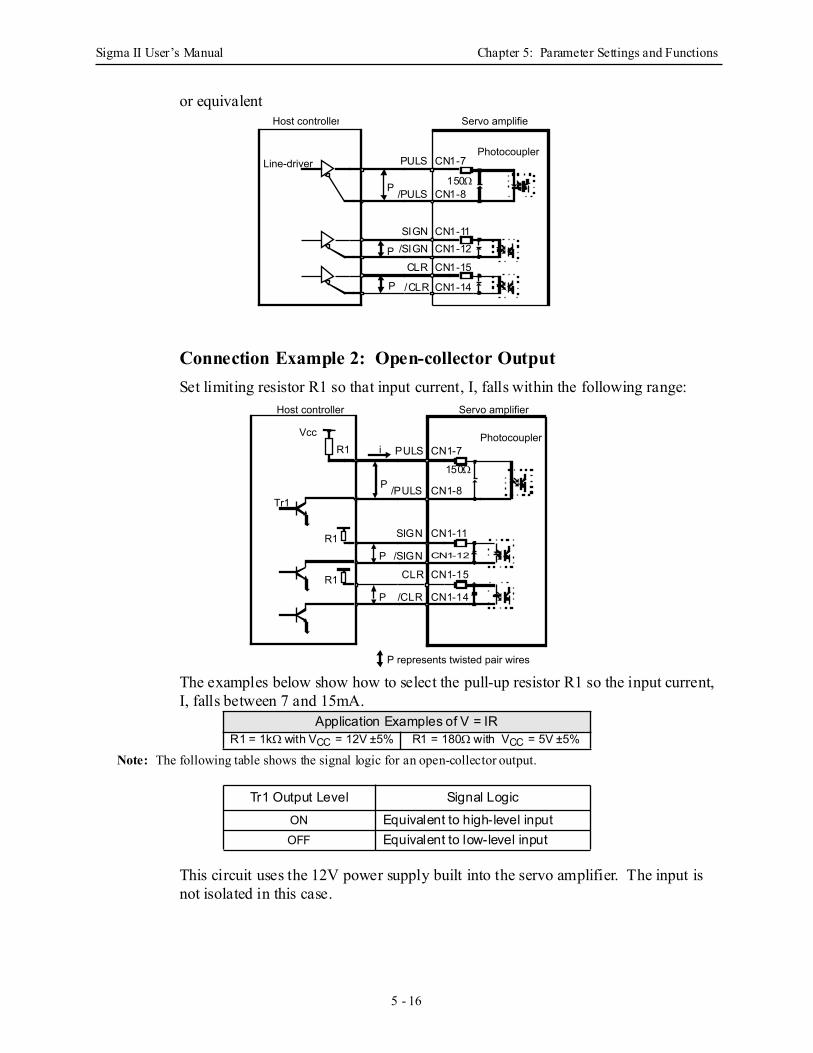
Sigma II User’s Manual Chapter 5: Parameter Settings and Functions
5 - 16
or equivalent
Connection Example 2: Open-collector Output Set limiting resistor R1 so that input current, I, falls within the following range:
The examples below show how to select the pull-up resistor R1 so the input current, I, falls between 7 and 15mA.
Note: The following table shows the signal logic for an open-collector output.
This circuit uses the 12V power supply built into the servo amplifier. The input is not isolated in this case.
Application Examples of V = IRR1 = 1kΩ with VCC = 12V ±5% R1 = 180Ω with VCC = 5V ±5%
Tr1 Output Level Signal LogicON Equivalent to high-level input OFF Equivalent to low-level input
PhotocouplerLine-driver
P
Servo amplifie
P
P
Host controller
PULS
/PULS
SIGN/SIGN
CLR
/CLR
CN1-7
CN1-8
CN1-11CN1-12
CN1-15
CN1-14
150Ω
P represents twisted pair wires
Vcc
P
Servo amplifier
Photocoupler
Host controller
R1 i
Tr1
PR1
PR1
PULS
/PULS
SIGN
/SIGN
CLR
/CLR
CN1-7
CN1-8
CN1-11
CN1-12
CN1-15
CN1-14
150Ω
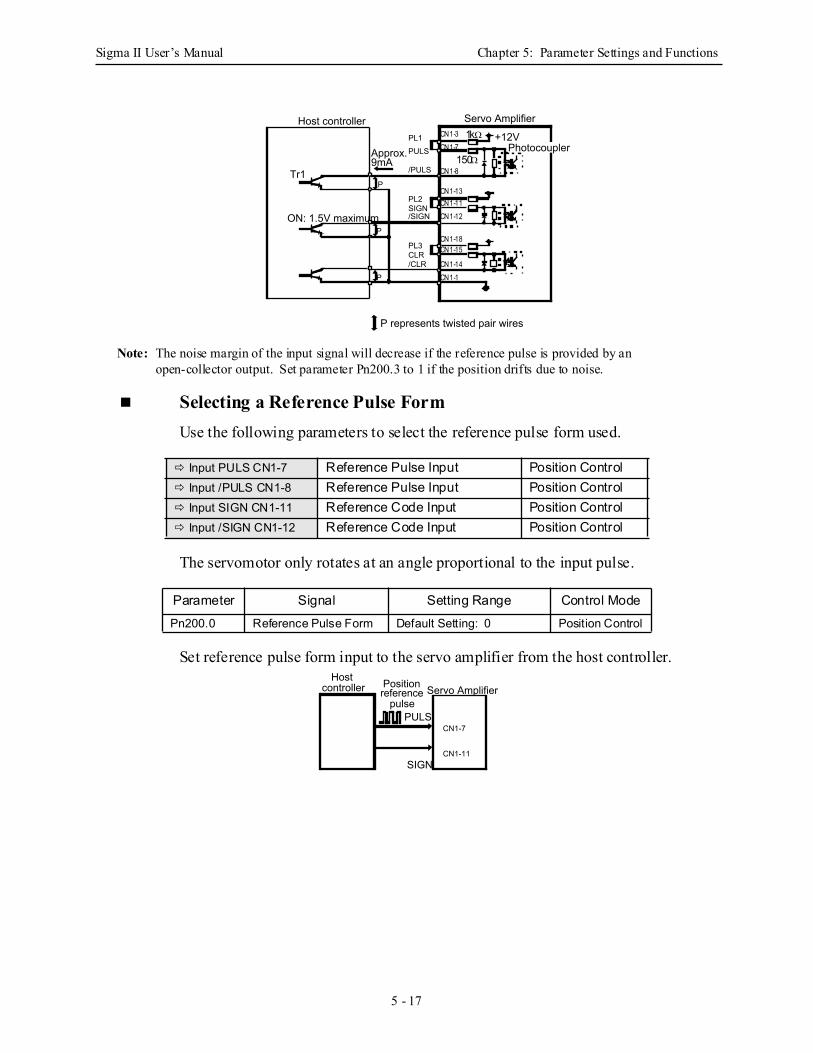
Sigma II User’s Manual Chapter 5: Parameter Settings and Functions
5 - 17
Note: The noise margin of the input signal will decrease if the reference pulse is provided by an open-collector output. Set parameter Pn200.3 to 1 if the position drifts due to noise.
Selecting a Reference Pulse Form Use the following parameters to select the reference pulse form used.
The servomotor only rotates at an angle proportional to the input pulse.
Set reference pulse form input to the servo amplifier from the host controller.
Input PULS CN1-7 Reference Pulse Input Position Control Input /PULS CN1-8 Reference Pulse Input Position Control Input SIGN CN1-11 Reference Code Input Position Control Input /SIGN CN1-12 Reference Code Input Position Control
Parameter Signal Setting Range Control ModePn200.0 Reference Pulse Form Default Setting: 0 Position Control
Servo Amplifier
+12VPhotocoupler
/PULS
PULSPL1
Approx. 9mA
Tr1
ON: 1.5V maximum /SIGNSIGNPL2
/CLRCLRPL3
P represents twisted pair wires
Host controller
P
P
P
150ΩCN1-7
CN1-8
CN1-11CN1-12
CN1-15
CN1-14
CN1-3
CN1-1
CN1-18
CN1-13
1kΩ
Servo Amplifier
CN1-7PULS
Position reference
pulse
CN1-11SIGN
Host controller
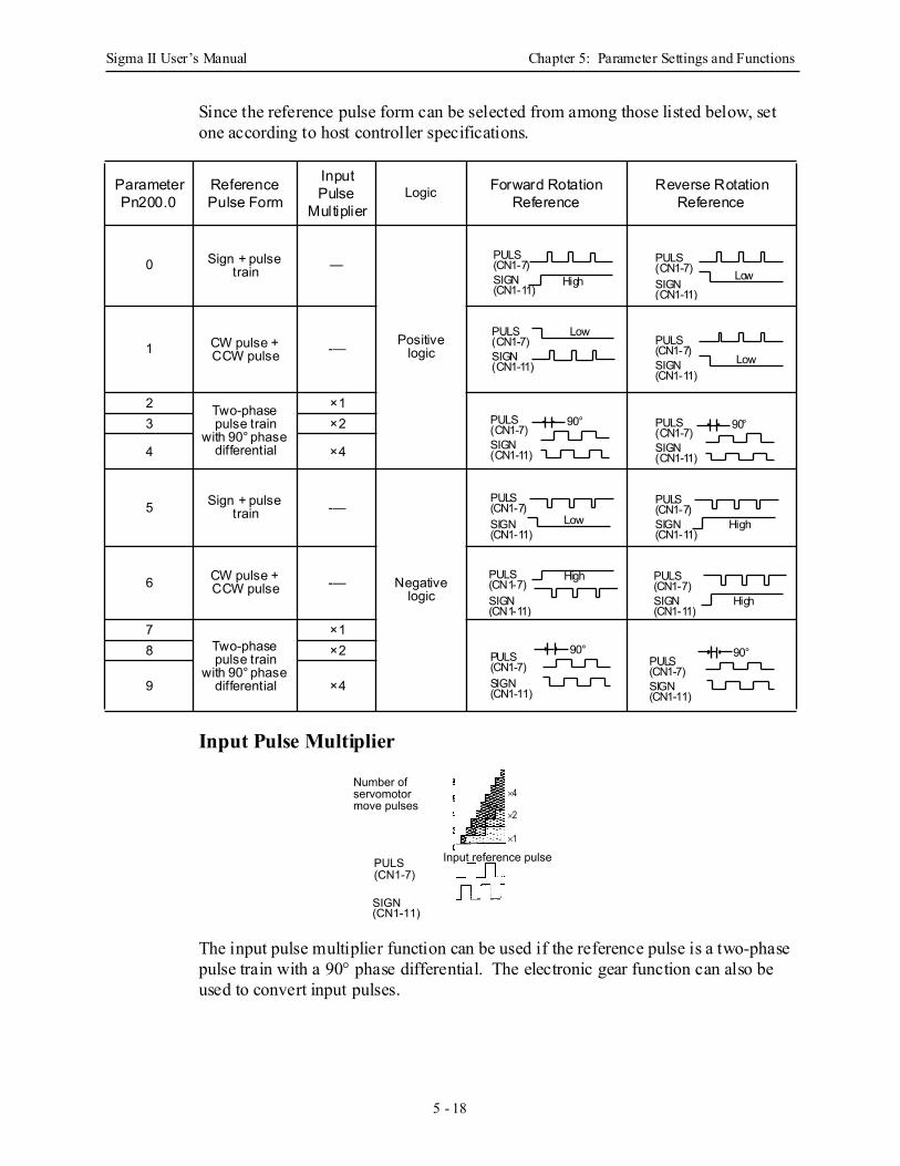
Sigma II User’s Manual Chapter 5: Parameter Settings and Functions
5 - 18
Since the reference pulse form can be selected from among those listed below, set one according to host controller specifications.
Input Pulse Multiplier
The input pulse multiplier function can be used if the reference pulse is a two-phase pulse train with a 90° phase differential. The electronic gear function can also be used to convert input pulses.
ParameterPn200.0
Reference Pulse Form
Input Pulse
Multiplier Logic Forward Rotation
Reference Reverse Rotation
Reference
0 Sign + pulse train —
Positive logic 1 CW pulse +
CCW pulse -—
2 Two-phase pulse train
with 90° phase differential
×13 ×2
4 ×4
5 Sign + pulse train -—
Negative logic
6 CW pulse + CCW pulse -—
7Two-phase pulse train
with 90° phase differential
×18 ×2
9 ×4
High
PULS(CN1-7)SIGN(CN1-11)
LowPULS(CN1-7)SIGN(CN1-11)
LowPULS(CN1-7)SIGN(CN1-11) Low
PULS(CN1-7)SIGN(CN1-11)
90°PULS(CN1-7)SIGN(CN1-11)
90°PULS(CN1-7)SIGN(CN1-11)
Low
PULS(CN1-7)SIGN(CN1-11)
High
PULS(CN1-7)SIGN(CN1-11)
HighPULS(CN1-7)SIGN(CN1-11)
High
PULS(CN1-7)SIGN(CN1-11)
90°PULS(CN1-7)SIGN(CN1-11)
90°PULS(CN1-7)SIGN(CN1-11)
Number of servomotor move pulses
Input reference pulse PULS (CN1-7)
SIGN (CN1-11)
×2
×1
×4
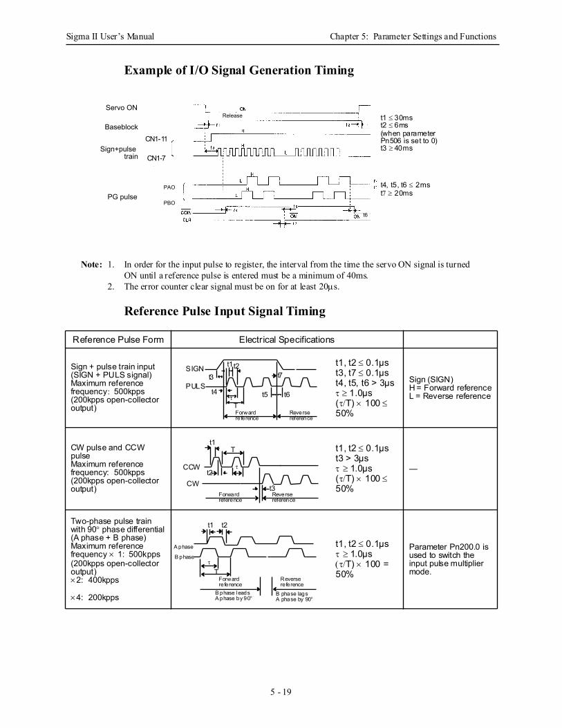
Sigma II User’s Manual Chapter 5: Parameter Settings and Functions
5 - 19
Example of I/O Signal Generation Timing
Note: 1. In order for the input pulse to register, the interval from the time the servo ON signal is turned ON until a reference pulse is entered must be a minimum of 40ms.
2. The error counter clear signal must be on for at least 20µs.
Reference Pulse Input Signal Timing
Reference Pulse Form Electrical Specifications
Sign + pulse train input (SIGN + PULS signal) Maximum reference frequency: 500kpps(200kpps open-collector output)
t1, t2 ≤ 0.1µst3, t7 ≤ 0.1µst4, t5, t6 > 3µsτ ≥ 1.0µs(τ/T) × 100 ≤ 50%
Sign (SIGN) H = Forward referenceL = Reverse reference
CW pulse and CCW pulse Maximum reference frequency: 500kpps(200kpps open-collector output)
t1, t2 ≤ 0.1µst3 > 3µsτ ≥ 1.0µs(τ/T) × 100 ≤ 50%
—
Two-phase pulse train with 90° phase differential (A phase + B phase) Maximum reference frequency × 1: 500kpps(200kpps open-collector output)×2: 400kpps
×4: 200kpps
t1, t2 ≤ 0.1µsτ ≥ 1.0µs(τ/T) × 100 = 50%
Parameter Pn200.0 is used to switch the input pulse multiplier mode.
Servo ON
Baseblock
Sign+pulse train
Release
PG pulse
CN1-11
CN1-7
PAO
PBO
t6
t1 ≤ 30mst2 ≤ 6ms(when parameterPn506 is set to 0)t3 ≥ 40ms
t4, t5, t6 ≤ 2mst7 ≥ 20ms
CN1-11
CN1-7
t7t2t1
t3
t4 t5 t6T
τ
Forwardreference
Reversereference
SIGN
PULS
Forwardreference
Reversereference
t2
t1
t3
T
τCCW
CW
Forwardreference
Reversereference
t2t1
Tτ
A phase
B phase
B phase leadsA phase by 90°
B phase lagsA phase by 90°
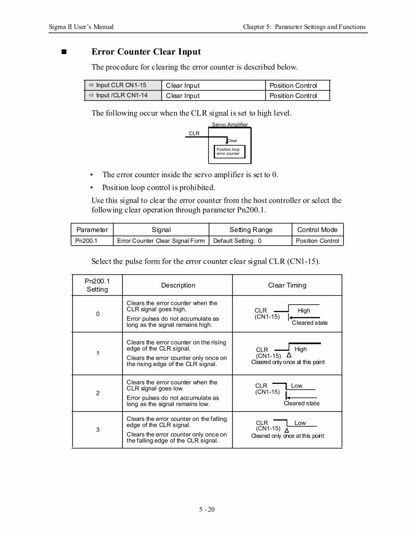
Sigma II User’s Manual Chapter 5: Parameter Settings and Functions
5 - 20
Error Counter Clear Input The procedure for clearing the error counter is described below.
The following occur when the CLR signal is set to high level.
• The error counter inside the servo amplifier is set to 0. • Position loop control is prohibited. Use this signal to clear the error counter from the host controller or select the following clear operation through parameter Pn200.1.
Select the pulse form for the error counter clear signal CLR (CN1-15).
Input CLR CN1-15 Clear Input Position Control Input /CLR CN1-14 Clear Input Position Control
Parameter Signal Setting Range Control ModePn200.1 Error Counter Clear Signal Form Default Setting: 0 Position Control
Pn200.1 Setting Description Clear Timing
0
Clears the error counter when the CLR signal goes high. Error pulses do not accumulate as long as the signal remains high.
1
Clears the error counter on the rising edge of the CLR signal. Clears the error counter only once on the rising edge of the CLR signal.
2
Clears the error counter when the CLR signal goes low.Error pulses do not accumulate as long as the signal remains low.
3
Clears the error counter on the falling edge of the CLR signal. Clears the error counter only once on the falling edge of the CLR signal.
Servo AmplifierCLR
Clear
Position loop error counter
CLR (CN1-15)
High
Cleared state
CLR (CN1-15)
High
Cleared only once at this point
CLR (CN1-15)
Low
Cleared state
CLR (CN1-15)
Low
Cleared only once at this point
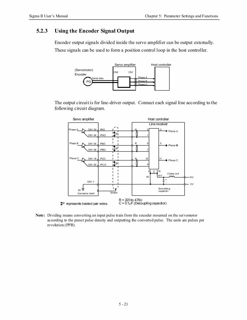
Sigma II User’s Manual Chapter 5: Parameter Settings and Functions
5 - 21
5.2.3 Using the Encoder Signal Output
Encoder output signals divided inside the servo amplifier can be output externally.These signals can be used to form a position control loop in the host controller.
The output circuit is for line-driver output. Connect each signal line according to the following circuit diagram.
Note: Dividing means converting an input pulse train from the encoder mounted on the servomotor according to the preset pulse density and outputting the converted pulse. The units are pulses per revolution (PPR).
PG
Servo amplifier
CN2 CN1(Servomotor) Encoder
Host controller
Phase A Phase BPhase C
Serial data
/PBO
R = 220 to 470ΩC = 0.1µF (Decoupling capacitor)
PBO
P
P
P represents twisted pair wires.
P
/PCO
PCO
/PAO
PAOPhase A
Phase B
Phase C
CN1-33
CN1-34
CN1-35
CN1-36
CN1-19
CN1-20
CN1-1
Phase A
Phase B
Phase C
0V
Choke co il
Smoothingcapaci tor
16
0V +5V
8
9
10
7
C
+-
+5V
11
0V
6 5
32
1
R
R
R
Servo amplifier Host controllerLine receiver
ShieldConnector shell
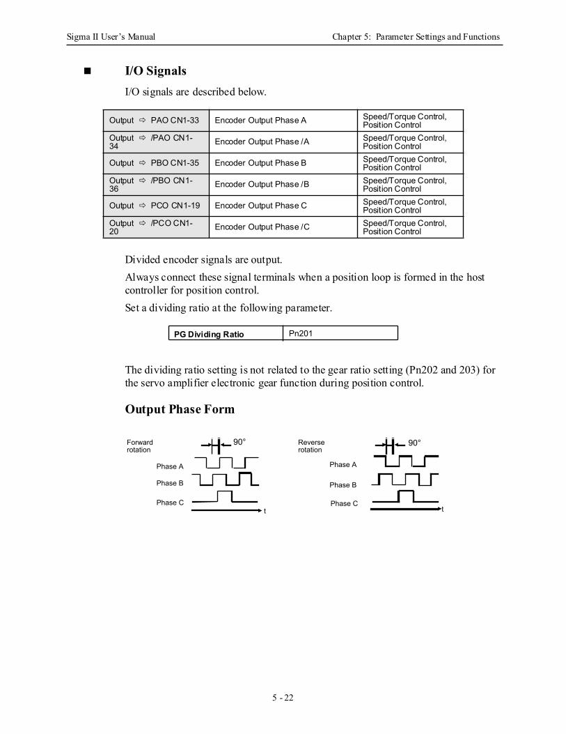
Sigma II User’s Manual Chapter 5: Parameter Settings and Functions
5 - 22
I/O Signals I/O signals are described below.
Divided encoder signals are output. Always connect these signal terminals when a position loop is formed in the host controller for position control. Set a dividing ratio at the following parameter.
The dividing ratio setting is not related to the gear ratio setting (Pn202 and 203) for the servo amplifier electronic gear function during position control.
Output Phase Form
Output PAO CN1-33 Encoder Output Phase A Speed/Torque Control, Position Control
Output /PAO CN1-34 Encoder Output Phase /A Speed/Torque Control,
Position Control
Output PBO CN1-35 Encoder Output Phase B Speed/Torque Control, Position Control
Output /PBO CN1-36 Encoder Output Phase /B Speed/Torque Control,
Position Control
Output PCO CN1-19 Encoder Output Phase C Speed/Torque Control, Position Control
Output /PCO CN1-20 Encoder Output Phase /C Speed/Torque Control,
Position Control
PG Dividing Ratio Pn201
Forward rotation
Reverse rotation
Phase A
Phase Ct t
Phase A
Phase B Phase B
Phase C
90° 90°
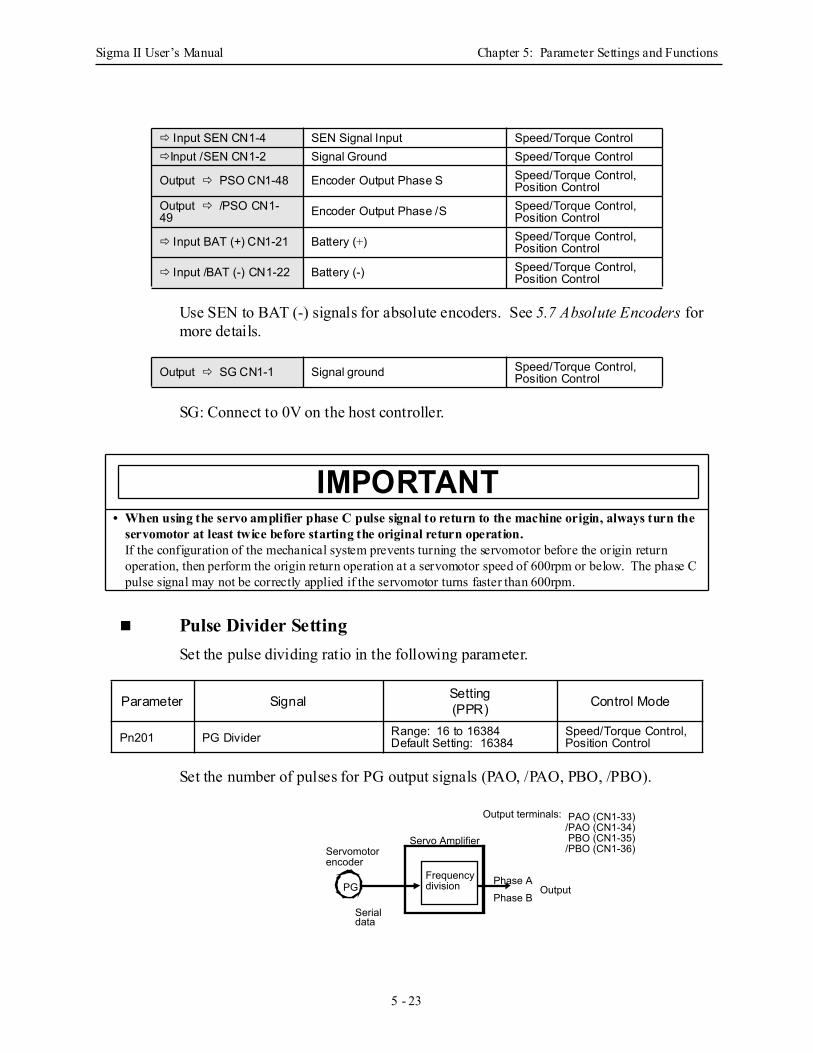
Sigma II User’s Manual Chapter 5: Parameter Settings and Functions
5 - 23
Use SEN to BAT (-) signals for absolute encoders. See 5.7 Absolute Encoders for more details.
SG: Connect to 0V on the host controller.
Pulse Divider Setting Set the pulse dividing ratio in the following parameter.
Set the number of pulses for PG output signals (PAO, /PAO, PBO, /PBO).
Input SEN CN1-4 SEN Signal Input Speed/Torque ControlInput /SEN CN1-2 Signal Ground Speed/Torque Control
Output PSO CN1-48 Encoder Output Phase S Speed/Torque Control, Position Control
Output /PSO CN1-49 Encoder Output Phase /S Speed/Torque Control,
Position Control
Input BAT (+) CN1-21 Battery (+) Speed/Torque Control, Position Control
Input /BAT (-) CN1-22 Battery (-) Speed/Torque Control, Position Control
Output SG CN1-1 Signal ground Speed/Torque Control, Position Control
• When using the servo amplifier phase C pulse signal to return to the machine origin, always turn the servomotor at least twice before starting the original return operation.If the configuration of the mechanical system prevents turning the servomotor before the origin return operation, then perform the origin return operation at a servomotor speed of 600rpm or below. The phase C pulse signal may not be correctly applied if the servomotor turns faster than 600rpm.
Parameter Signal Setting(PPR) Control Mode
Pn201 PG Divider Range: 16 to 16384Default Setting: 16384
Speed/Torque Control, Position Control
IMPORTANT
Output terminals: PAO (CN1-33)/PAO (CN1-34) PBO (CN1-35)/PBO (CN1-36)
Phase APhase B
Output
Servo AmplifierServomotor encoder
Serial data
PGFrequency division
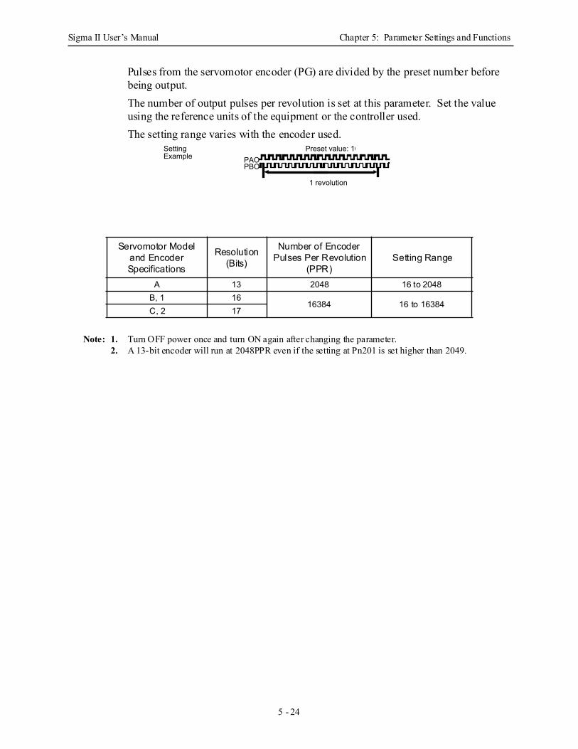
Sigma II User’s Manual Chapter 5: Parameter Settings and Functions
5 - 24
Pulses from the servomotor encoder (PG) are divided by the preset number before being output. The number of output pulses per revolution is set at this parameter. Set the value using the reference units of the equipment or the controller used. The setting range varies with the encoder used.
Note: 1. Turn OFF power once and turn ON again after changing the parameter.2. A 13-bit encoder will run at 2048PPR even if the setting at Pn201 is set higher than 2049.
Servomotor Model and Encoder Specifications
Resolution (Bits)
Number of Encoder Pulses Per Revolution
(PPR)Setting Range
A 13 2048 16 to 2048B, 1 16
16384 16 to 16384C, 2 17
Setting Example
Preset value: 16
1 revolution
PAOPBO
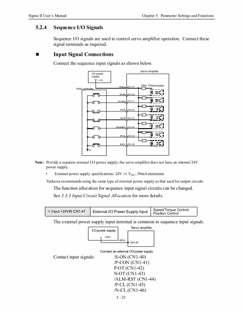
Sigma II User’s Manual Chapter 5: Parameter Settings and Functions
5 - 25
5.2.4 Sequence I/O Signals
Sequence I/O signals are used to control servo amplifier operation. Connect these signal terminals as required.
Input Signal Connections Connect the sequence input signals as shown below.
Note: Provide a separate external I/O power supply; the servo amplifier does not have an internal 24V power supply.
• External power supply specifications: 24V ±1 VD C, 50mA minimum.
Yaskawa recommends using the same type of external power supply as that used for output circuits.
The function allocation for sequence input signal circuits can be changed. See 5.3.3 Input Circuit Signal Allocation for more details.
The external power supply input terminal is common to sequence input signals.
Contact input signals: /S-ON (CN1-40)/P-CON (CN1-41)P-OT (CN1-42)N-OT (CN1-43)/ALM-RST (CN1-44)/P-CL (CN1-45)/N-CL (CN1-46)
Input +24VIN CN1-47 External I/O Power Supply Input Speed/Torque Control, Position Control
I/O power supply
CN1-47
CN1-40
CN1-41
CN1-42
CN1-43
CN1-44
CN1-45
CN1-46
0V
+ 24V
Servo Amplifier
PhotocouplerHost controller
+24VIN
/S-ON
/P-CON
P-OT
N-OT
/ALM-RST
/P-CL
/N-CL
3.3kΩ
Servo amplifierI/O power supply
Connect an external I/O power supply
+24V+24Vin
CN1-47
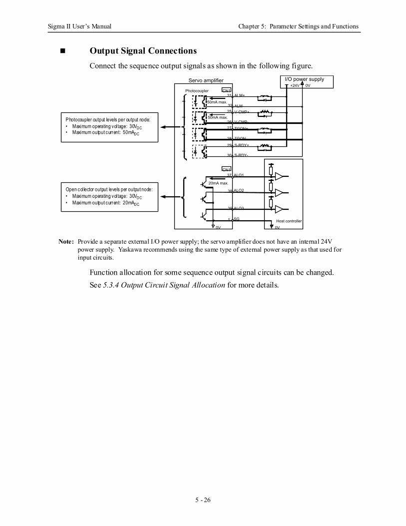
Sigma II User’s Manual Chapter 5: Parameter Settings and Functions
5 - 26
Output Signal Connections Connect the sequence output signals as shown in the following figure.
Note: Provide a separate external I/O power supply; the servo amplifier does not have an internal 24V power supply. Yaskawa recommends using the same type of external power supply as that used for input circuits.
Function allocation for some sequence output signal circuits can be changed. See 5.3.4 Output Circuit Signal Allocation for more details.
0V 0VHost controller
Servo amplifier
Photocoupler
50mA max.31
CN1
3225
2627
2829
30
ALM+
ALM-V-CMP+
V-CMP-TGON+
TGON-S-RDY+
S-RDY-
50mA max.
20mA max.
37
38
39
1
ALO1
ALO2
ALO3
SG
CN1
I/O power supply +24V 0V
~
~
~
~
Photocoupler output levels per output node:• Maximum operating voltage: 30VDC• Maximum output current: 50mADC
Open collector output levels per output node:• Maximum operating voltage: 30VDC• Maximum output current: 20mADC
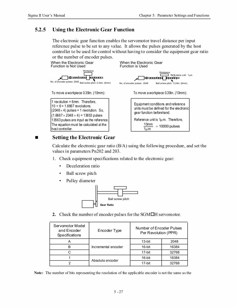
Sigma II User’s Manual Chapter 5: Parameter Settings and Functions
5 - 27
5.2.5 Using the Electronic Gear Function
The electronic gear function enables the servomotor travel distance per input reference pulse to be set to any value. It allows the pulses generated by the host controller to be used for control without having to consider the equipment gear ratio or the number of encoder pulses.
Setting the Electronic Gear Calculate the electronic gear ratio (B/A) using the following procedure, and set the values in parameters Pn202 and 203. 1. Check equipment specifications related to the electronic gear:
• Deceleration ratio • Ball screw pitch • Pulley diameter
2. Check the number of encoder pulses for the SGM H servomotor.
Note: The number of bits representing the resolution of the applicable encoder is not the same as the
Servomotor Model and Encoder
Specifications Encoder Type Number of Encoder Pulses
Per Revolution (PPR)
AIncremental encoder
13-bit 2048B 16-bit 16384C 17-bit 327681
Absolute encoder 16-bit 16384
2 17-bit 32768
When the Electronic Gear Function is Not Used
When the Electronic Gear Function is Used
Ball screw pitch: 0.24in. (6mm)
Workpiece
No. of encoder pulses: 2048No. of encoder pulses: 2048
Workpiece
Ball screw pitch: 0.24in. (6mm)
Reference unit: 1µm
To move a workpiece 0.39in. (10mm):
1 revolution = 6mm. Therefore,10 ÷ 6 = 1.6667 revolutions.(2048 × 4) pulses = 1 revolution. So,(1.6667 × 2048 × 4) = 13653 pulses13563 pulses are input as the reference.The equation must be calculated at thehost controller.
To move a workpiece 0.39in. (10mm):
Equipment conditions and referenceunits must be defined for the electronicgear function beforehand.
Reference unit is 1µm. Therefore,10mm1µm
= 10000 pulses
Ball screw pitch
Deceleration ratioGear Ratio
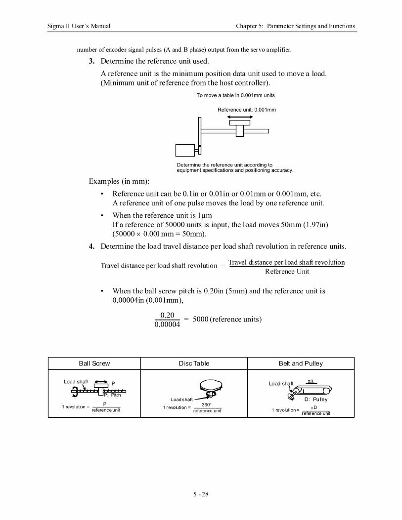
Sigma II User’s Manual Chapter 5: Parameter Settings and Functions
5 - 28
number of encoder signal pulses (A and B phase) output from the servo amplifier. 3. Determine the reference unit used.
A reference unit is the minimum position data unit used to move a load. (Minimum unit of reference from the host controller).
Examples (in mm):• Reference unit can be 0.1in or 0.01in or 0.01mm or 0.001mm, etc.
A reference unit of one pulse moves the load by one reference unit.• When the reference unit is 1µm
If a reference of 50000 units is input, the load moves 50mm (1.97in)(50000 × 0.001mm = 50mm).
4. Determine the load travel distance per load shaft revolution in reference units.
• When the ball screw pitch is 0.20in (5mm) and the reference unit is 0.00004in (0.001mm),
Ball Screw Disc Table Belt and Pulley
Reference unit: 0.001mm
Determine the reference unit according to equipment specifications and positioning accuracy.
To move a table in 0.001mm units
Travel distance per load shaft revolution = Travel distance per load shaft revolutionReference Unit
0.200.00004------------------- 5000= (reference units)
Load shaft P
1 revolution = Preference unit
P: PitchL d h fLoad shaft
1 revolution = 360°reference unit 1 revolution = πD
reference unit
D: Pulley
π∆Load shaft
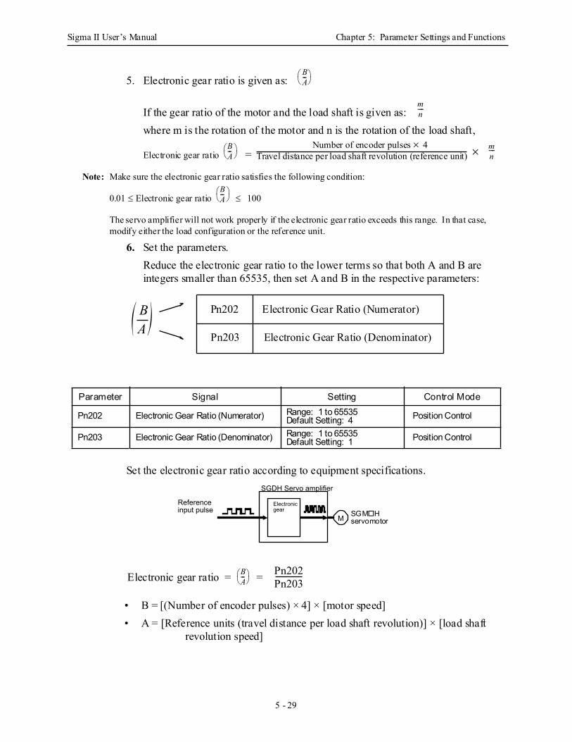
Sigma II User’s Manual Chapter 5: Parameter Settings and Functions
5 - 29
5. Electronic gear ratio is given as:
If the gear ratio of the motor and the load shaft is given as: where m is the rotation of the motor and n is the rotation of the load shaft,
Electronic gear ratio =
Note: Make sure the electronic gear ratio satisfies the following condition:
0.01 ≤ Electronic gear ratio ≤ 100
The servo amplifier will not work properly if the electronic gear ratio exceeds this range. In that case, modify either the load configuration or the reference unit.
6. Set the parameters. Reduce the electronic gear ratio to the lower terms so that both A and B are integers smaller than 65535, then set A and B in the respective parameters:
Set the electronic gear ratio according to equipment specifications.
• B = [(Number of encoder pulses) × 4] × [motor speed] • A = [Reference units (travel distance per load shaft revolution)] × [load shaft
revolution speed]
Parameter Signal Setting Control Mode
Pn202 Electronic Gear Ratio (Numerator) Range: 1 to 65535Default Setting: 4 Position Control
Pn203 Electronic Gear Ratio (Denominator) Range: 1 to 65535Default Setting: 1 Position Control
BA---
mn----
BA---
Number of encoder pulses × 4Travel distance per load shaft revolution (reference unit) × m
n----
BA---
BA( ) Pn202
Pn203
Electronic Gear Ratio (Numerator)
Electronic Gear Ratio (Denominator)
M
Reference input pulse
SGDH Servo amplifier
Electronic gear SGM H
servomotor
Electronic gear ratio = = BA---
Pn202Pn203
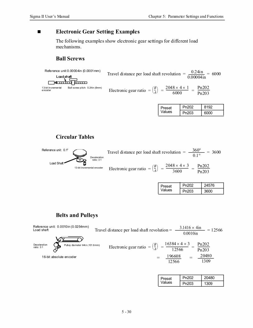
Sigma II User’s Manual Chapter 5: Parameter Settings and Functions
5 - 30
Electronic Gear Setting Examples The following examples show electronic gear settings for different load mechanisms.
Ball Screws
Circular Tables
Belts and Pulleys
Preset Values
Pn202 8192Pn203 6000
Preset Values
Pn202 24576Pn203 3600
Preset Values
Pn202 20480Pn203 1309
Electronic gear ratio = = = BA---
Pn202Pn203
Travel distance per load shaft revolution = = 6000
2048 × 4 × 16000
0.24in0.00004inLoad shaft
13-bi t incrementalencoder
Ball screw p itch: 0.24 in (6mm)
Reference unit 0.00004in (0.0001mm)
Load shaft
13-bit Incremental encoder
Deceleration ratio: 3:1
Electronic gear ratio = = = BA---
Pn202Pn203
Travel distance per load shaft revolution = = 3600
2048 × 4 × 33600
360°0.1°
Load Shaft
Reference unit: 0.1°
Electronic gear ratio = = = BA---
Pn202Pn203
Travel distance per load shaft revolution =
16384 × 4 × 312566
3.1416 × 4in 0.0010in
= =19660812566
204801309
Reference unit: 0.0010in (0.0254mm)Load shaft
16-bit absolute encoder
Decelerationratio: 3:1
Pulley diameter Φ4in (101.6mm)
= 12566
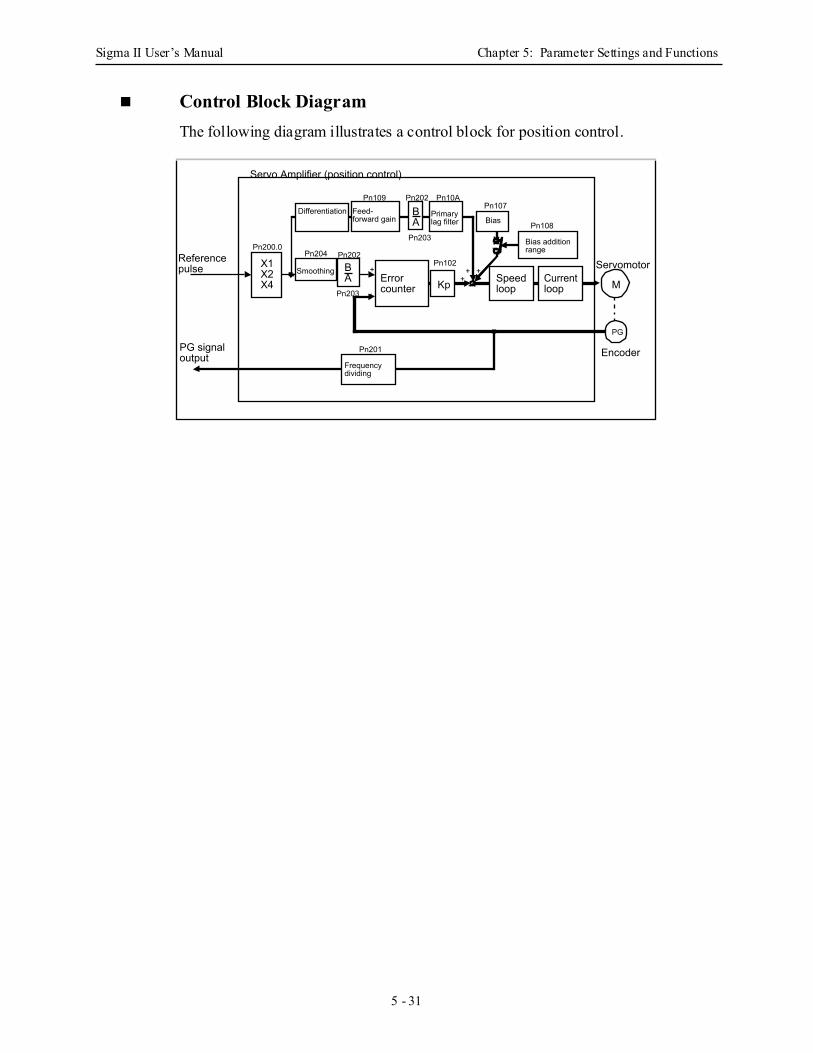
Sigma II User’s Manual Chapter 5: Parameter Settings and Functions
5 - 31
Control Block Diagram The following diagram illustrates a control block for position control.
Differentiation
Smoothing X1X2X4 Error
counter Kp
Feed-forward gain Primary
lag filter Bias
Speed loop
Current loop M
Frequency dividing
Pn201
Pn204 Pn202
Pn203
+
-
Pn102
Pn203
Pn202 Pn10APn107
Pn109
Servomotor
PG
Pn200.0Reference pulse
PG signal output
Servo Amplifier (position control)
Encoder
Bias addition range
Pn108
++ +
BA
BA
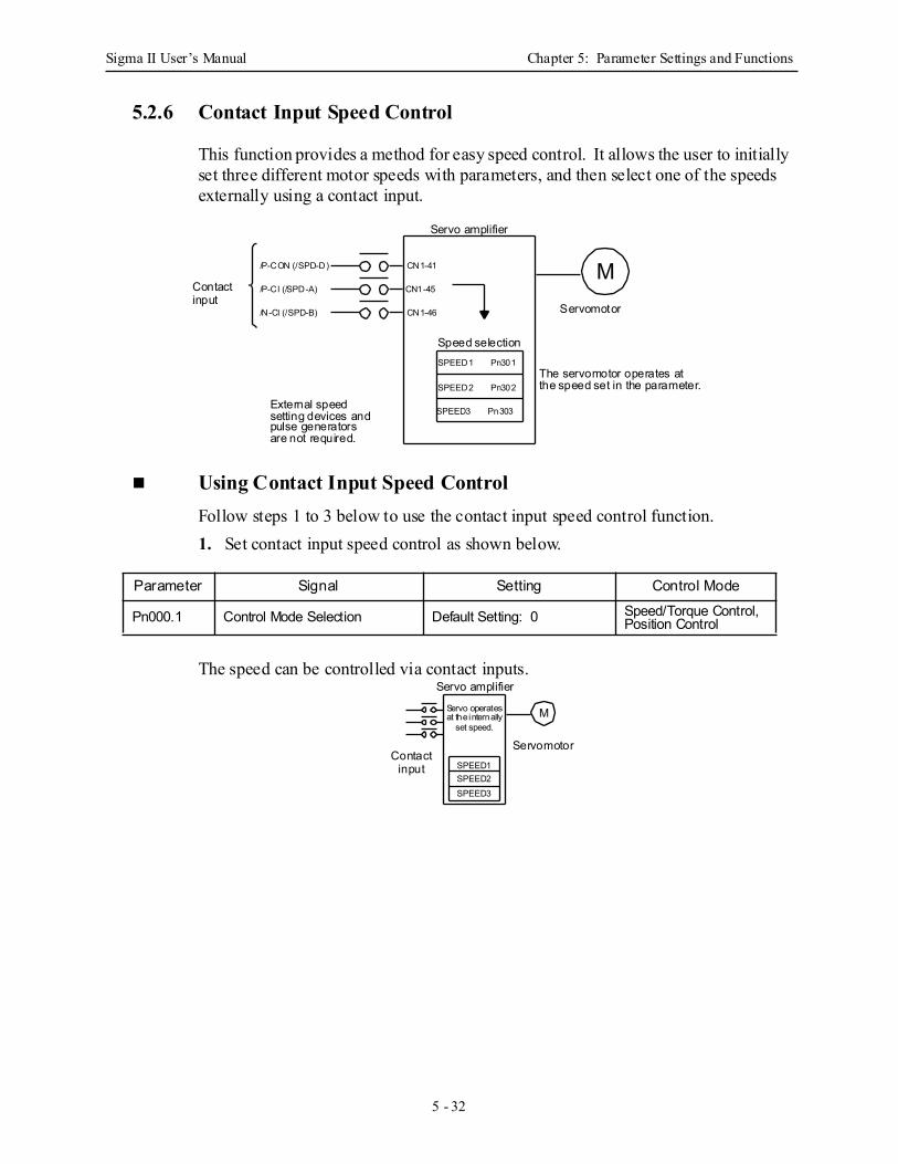
Sigma II User’s Manual Chapter 5: Parameter Settings and Functions
5 - 32
5.2.6 Contact Input Speed Control
This function provides a method for easy speed control. It allows the user to initially set three different motor speeds with parameters, and then select one of the speeds externally using a contact input.
Using Contact Input Speed Control Follow steps 1 to 3 below to use the contact input speed control function. 1. Set contact input speed control as shown below.
The speed can be controlled via contact inputs.
Parameter Signal Setting Control Mode
Pn000.1 Control Mode Selection Default Setting: 0 Speed/Torque Control, Position Control
The servomotor operates atthe speed set in the parameter.
M
Servo amplifier
Servomotor
Speed selection
External speed
SPEED1 Pn301
SPEED2 Pn302
SPEED3 Pn303setting devices andpulse generatorsare not required.
CN1-41
CN1-45
CN1-46
Contactinput
/P-CON (/SPD-D)
/P-Cl (/SPD-A)
/N-Cl (/SPD-B)
M
Servo amplifier
ServomotorContact
input SPEED1SPEED2SPEED3
Servo operatesat the internally
set speed.
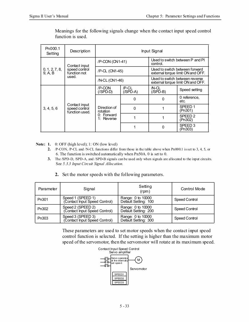
Sigma II User’s Manual Chapter 5: Parameter Settings and Functions
5 - 33
Meanings for the following signals change when the contact input speed control function is used.
Note: 1. 0: OFF (high level); 1: ON (low level)2. /P-CON, /P-CL and /N-CL functions differ from those in the table above when Pn000.1 is set to 3, 4, 5, or
6. The function is switched automatically when Pn50A. 0 is set to 0.3. The /SPD-D, /SPD-A, and /SPD-B signals can be used only when signals are allocated to the input circuits.
See 5.3.3 Input Circuit Signal Allocation.
2. Set the motor speeds with the following parameters.
These parameters are used to set motor speeds when the contact input speed control function is selected. If the setting is higher than the maximum motor speed of the servomotor, then the servomotor will rotate at its maximum speed.
Pn000.1 Setting Description Input Signal
0, 1, 2, 7, 8, 9, A, B
Contact input speed control function not used.
/P-CON (CN1-41) Used to switch between P and PI control.
/P-CL (CN1-45) Used to switch between forward external torque limit ON and OFF.
/N-CL (CN1-46) Used to switch between reverse external torque limit ON and OFF.
3, 4, 5, 6Contact input speed control function used.
/P-CON(/SPD-D)
/P-CL (/SPD-A)
/N-CL (/SPD-B) Speed setting
Direction of rotation 0: Forward 1: Reverse
0 0 0 reference,etc.
0 1 SPEED 1 (Pn301)
1 1 SPEED 2 (Pn302)
1 0 SPEED 3 (Pn303)
Parameter Signal Setting(rpm) Control Mode
Pn301 Speed 1 (SPEED 1) (Contact Input Speed Control)
Range: 0 to 10000Default Setting: 100 Speed Control
Pn302 Speed 2 (SPEED 2) (Contact Input Speed Control)
Range: 0 to 10000Default Setting: 200 Speed Control
Pn303 Speed 3 (SPEED 3) (Contact Input Speed Control)
Range: 0 to 10000Default Setting: 300 Speed Control
Servo operatesat the internallyset speed.
SPEED1SPEED2SPEED3
M
Servomotor
Servo amplifierContact Input Speed Control
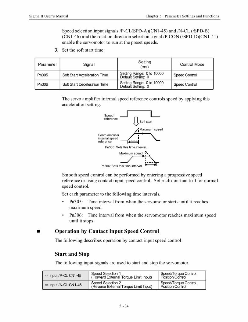
Sigma II User’s Manual Chapter 5: Parameter Settings and Functions
5 - 34
Speed selection input signals /P-CL(SPD-A)(CN1-45) and /N-CL (/SPD-B) (CN1-46) and the rotation direction selection signal /P-CON (/SPD-D)(CN1-41) enable the servomotor to run at the preset speeds.
3. Set the soft start time.
The servo amplifier internal speed reference controls speed by applying this acceleration setting.
Smooth speed control can be performed by entering a progressive speed reference or using contact input speed control. Set each constant to 0 for normal speed control. Set each parameter to the following time intervals. • Pn305: Time interval from when the servomotor starts until it reaches
maximum speed. • Pn306: Time interval from when the servomotor reaches maximum speed
until it stops.
Operation by Contact Input Speed Control The following describes operation by contact input speed control.
Start and Stop The following input signals are used to start and stop the servomotor.
Parameter Signal Setting(ms) Control Mode
Pn305 Soft Start Acceleration Time Setting Range: 0 to 10000Default Setting: 0 Speed Control
Pn306 Soft Start Deceleration Time Setting Range: 0 to 10000Default Setting: 0 Speed Control
Input /P-CL CN1-45 Speed Selection 1(Forward External Torque Limit Input)
Speed/Torque Control, Position Control
Input /N-CL CN1-46 Speed Selection 2(Reverse External Torque Limit Input)
Speed/Torque Control, Position Control
Servo amplifier internal speed reference
Speed reference
Soft start
Maximum speed
Pn305: Sets this time interval.
Maximum speed
Pn306: Sets this time interval.

Sigma II User’s Manual Chapter 5: Parameter Settings and Functions
5 - 35
Use the following table when contact input speed control is used.
Note: 1. 0: OFF (high level); 1: ON (low level)2. Input signals indicated by the horizontal bar (-) are optional.
• When contact input speed control is not used, input signals are used as external torque limit inputs.
Note: The contact input speed control function is used only when signals are allocated to /SPD-D, /SPD-A, and /SPD-B.
Direction of Rotation Selection The input signal /P-CON(/SPD-D) is used to specify the direction of servomotor rotation.
• When contact input speed control is used, the input signal /P-CON (/SPD-D) specifies the direction of servomotor rotation.
Note: 0: OFF (high level); 1: ON (low level)
• When contact input speed control is not used, the /P-CON signal is used for proportional control, zero clamping, and torque/speed control switching.
Contact Signal Parameter Selected Speed /P-CON
(/SPD-D)/P-CL
(/SPD-A)/N-CL
(/SPD-B) Pn000.1
- 0 0
3 Stopped by an internal speed reference of 0.
4 Analog speed reference (V-REF) input
5 Pulse reference input (position control)
6 Analog torque reference input (torque control)
Direction of rotation 0: Forward1: Reverse
0 13, 4, 5, 6, Common
SPEED 1 (Pn301)1 1 SPEED 2 (Pn302)1 0 SPEED 3 (Pn303)
Input /P-CON CN1-41 Proportional Control Reference, etc. Speed/Torque Control, Position Control
/P-CON (/SPD-D) Input Level Signal Logic
0 Forward rotation 1 Reverse rotation
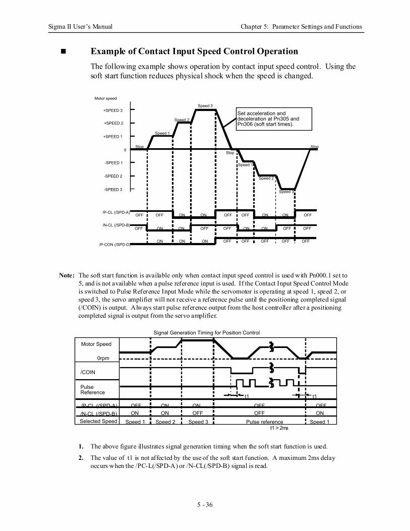
Sigma II User’s Manual Chapter 5: Parameter Settings and Functions
5 - 36
Example of Contact Input Speed Control Operation The following example shows operation by contact input speed control. Using the soft start function reduces physical shock when the speed is changed.
Note: The soft start function is available only when contact input speed control is used with Pn000.1 set to 5, and is not available when a pulse reference input is used. If the Contact Input Speed Control Mode is switched to Pulse Reference Input Mode while the servomotor is operating at speed 1, speed 2, or speed 3, the servo amplifier will not receive a reference pulse until the positioning completed signal (/COIN) is output. Always start pulse reference output from the host controller after a positioning completed signal is output from the servo amplifier.
1. The above figure illustrates signal generation timing when the soft start function is used.
2. The value of t1 is not affected by the use of the soft start function. A maximum 2ms delayoccurs when the /PC-L(/SPD-A) or /N-CL(/SPD-B) signal is read.
-SPEED 1
Motor speed
+SPEED 3
+SPEED 2
+SPEED 1
-SPEED 2
-SPEED 3
0
OFF ON
Speed 1
Stop
Set acceleration and deceleration at Pn305 and Pn306 (soft start times).
/P-CL (/SPD-A)
/N-CL (/SPD-B)
/P-CON (/SPD-D)
Speed 2
Speed 3
StopStop
Speed 1
Speed 2
Speed 3
OFF OFF OFF OFF
OFF OFF OFF OFF OFF
OFF OFF OFF OFF OFF
ON ON ON
ON ON ON ON
ON ON ON
t1 > 2ms
/N-CL (/SPD-B)/P-CL (/SPD-A)
ONSpeed 1Selected Speed
ONOFF ON OFF
OFF OFFPulse reference
ON OFFON
/COIN
Pulse Reference
0rpm
Motor Speed
t1
Signal Generation Timing for Position Control
t1
Speed 2 Speed 3 Speed 1
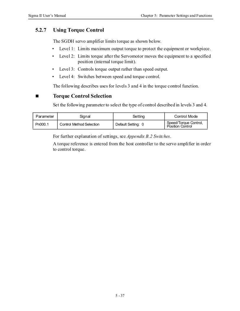
Sigma II User’s Manual Chapter 5: Parameter Settings and Functions
5 - 37
5.2.7 Using Torque Control
The SGDH servo amplifier limits torque as shown below. • Level 1: Limits maximum output torque to protect the equipment or workpiece. • Level 2: Limits torque after the Servomotor moves the equipment to a specified
position (internal torque limit). • Level 3: Controls torque output rather than speed output. • Level 4: Switches between speed and torque control.
The following describes uses for levels 3 and 4 in the torque control function.
Torque Control Selection Set the following parameter to select the type of control described in levels 3 and 4.
For further explanation of settings, see Appendix B.2 Switches. A torque reference is entered from the host controller to the servo amplifier in order to control torque.
Parameter Signal Setting Control Mode
Pn000.1 Control Method Selection Default Setting: 0 Speed/Torque Control, Position Control
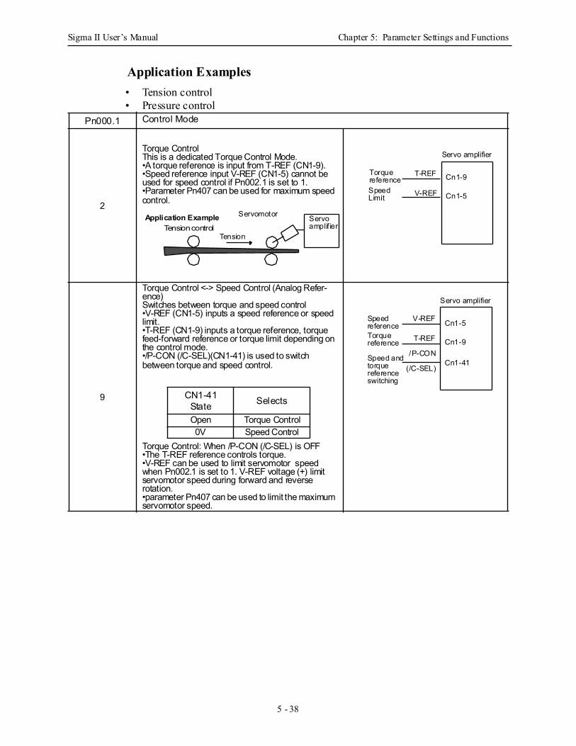
Sigma II User’s Manual Chapter 5: Parameter Settings and Functions
5 - 38
Application Examples • Tension control • Pressure control
Pn000.1 Control Mode
2
Torque Control This is a dedicated Torque Control Mode. •A torque reference is input from T-REF (CN1-9). •Speed reference input V-REF (CN1-5) cannot be used for speed control if Pn002.1 is set to 1. •Parameter Pn407 can be used for maximum speed control.
9
Torque Control <-> Speed Control (Analog Refer-ence) Switches between torque and speed control •V-REF (CN1-5) inputs a speed reference or speed limit. •T-REF (CN1-9) inputs a torque reference, torque feed-forward reference or torque limit depending on the control mode. •/P-CON (/C-SEL)(CN1-41) is used to switch between torque and speed control.
Torque Control: When /P-CON (/C-SEL) is OFF •The T-REF reference controls torque. •V-REF can be used to limit servomotor speed when Pn002.1 is set to 1. V-REF voltage (+) limit servomotor speed during forward and reverse rotation. •parameter Pn407 can be used to limit the maximum servomotor speed.
Tension controlTension
Servomotor Servoamplif ier
Application Example
Servo amplifier
T-REF
V-REF
Cn1-9
Cn1-5
TorquereferenceSpeedLimit
CN1-41 State Selects
Open Torque Control0V Speed Control
Servo amplifier
V-REF
T-REF
Cn1-5
Cn1-9
SpeedreferenceTorquereference
Speed andtorquereference switching
/P-CON
(/C-SEL)Cn1-41
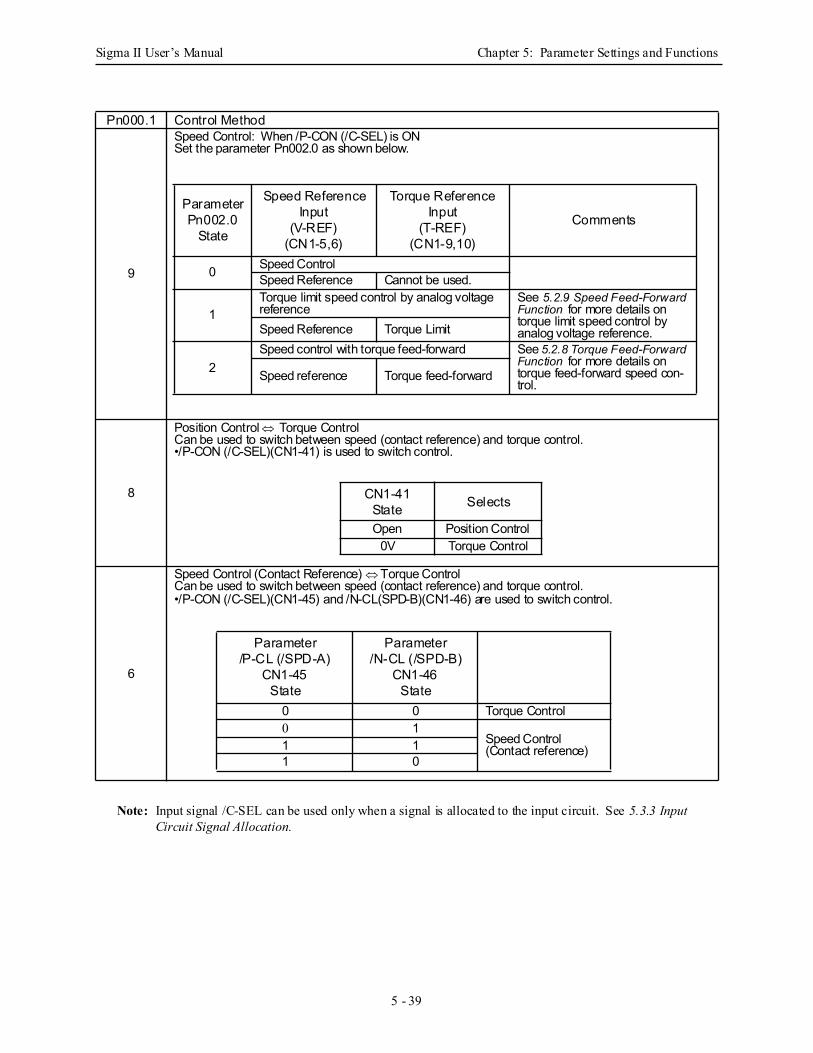
Sigma II User’s Manual Chapter 5: Parameter Settings and Functions
5 - 39
Note: Input signal /C-SEL can be used only when a signal is allocated to the input circuit. See 5.3.3 Input Circuit Signal Allocation.
Pn000.1 Control Method
9
Speed Control: When /P-CON (/C-SEL) is ON Set the parameter Pn002.0 as shown below.
8
Position Control ⇔ Torque Control Can be used to switch between speed (contact reference) and torque control. •/P-CON (/C-SEL)(CN1-41) is used to switch control.
6
Speed Control (Contact Reference) ⇔ Torque Control Can be used to switch between speed (contact reference) and torque control. •/P-CON (/C-SEL)(CN1-45) and /N-CL(SPD-B)(CN1-46) are used to switch control.
ParameterPn002.0
State
Speed Reference Input
(V-REF)(CN1-5,6)
Torque Reference Input
(T-REF)(CN1-9,10)
Comments
0 Speed ControlSpeed Reference Cannot be used.
1Torque limit speed control by analog voltage reference
See 5.2.9 Speed Feed-Forward Function for more details on torque limit speed control by analog voltage reference. Speed Reference Torque Limit
2Speed control with torque feed-forward See 5.2.8 Torque Feed-Forward
Function for more details on torque feed-forward speed con-trol.
Speed reference Torque feed-forward
CN1-41 State Selects
Open Position Control0V Torque Control
Parameter/P-CL (/SPD-A)
CN1-45State
Parameter/N-CL (/SPD-B)
CN1-46State
0 0 Torque Control0 1
Speed Control(Contact reference)1 1
1 0
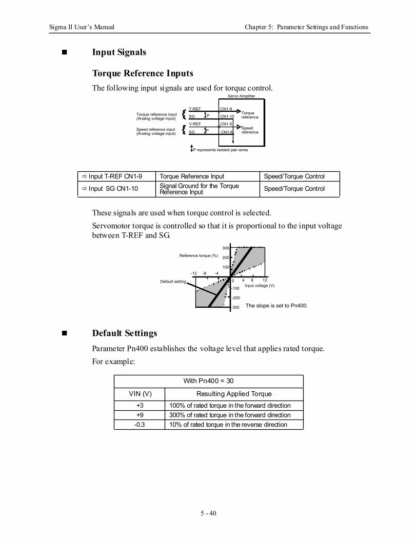
Sigma II User’s Manual Chapter 5: Parameter Settings and Functions
5 - 40
Input Signals
Torque Reference Inputs The following input signals are used for torque control.
These signals are used when torque control is selected. Servomotor torque is controlled so that it is proportional to the input voltage between T-REF and SG.
Default Settings Parameter Pn400 establishes the voltage level that applies rated torque. For example:
Input T-REF CN1-9 Torque Reference Input Speed/Torque Control
Input SG CN1-10 Signal Ground for the TorqueReference Input Speed/Torque Control
With Pn400 = 30
VIN (V) Resulting Applied Torque+3 100% of rated torque in the forward direction+9 300% of rated torque in the forward direction
-0.3 10% of rated torque in the reverse direction
P
PSG
V-REF
SG
T-REFTorque reference input (Analog voltage input)
Speed reference input (Analog voltage input)
Torque reference
Speed reference
Servo Amplifier
CN1-9
CN1-10
CN1-5
CN1-6
P represents twisted pair wires
300
200
100
-300
-200
-100
0
-4-8-124 8 12
Reference torque (%)
Input voltage (V)
The slope is set to Pn400.
Default setting

Sigma II User’s Manual Chapter 5: Parameter Settings and Functions
5 - 41
Example of an Input Circuit
Note:• Always use twisted pair cables for noise control.
• Recommended variable resistor: Model 25HP-10B manufactured by Sakae Tsushin Kogyo Co., Ltd.
Speed Reference InputsRefer to Section 5.2.1.
Using the /P-CON Signal
The function of the input signal /P-CON varies with the setting applied to Pn000.1.
Note: The /P-CON signal function switches automatically when Pn50A.0 is set to 0.
Input /P-CON CN1-41 Proportional Control Reference, etc. Speed/Torque Control, Position Control
Pn000.1 Setting /P-CON Function0, 1 Switches between P (proportional) and PI (proportional-integral) control.2 Not used.
3, 4, 5, 6 Switches the direction of rotation in Contact Input Speed Control Mode.7, 8, 9 Switches the control mode.
A Turns ON/OFF zero clamp.B Turns inhibit ON/OFF.
PSG
T-REF+12V
Servo Amplifier
CN1-9
CN1-10
1/2W minimum470Ω
2kΩ
Servo Amplifier
(Pn000.1)
P and PI control switching
Zero clamp ON/OFF switching
Inhibit ON/OFF switching
Control mode switching
Direction of rotation switching
P-CON/
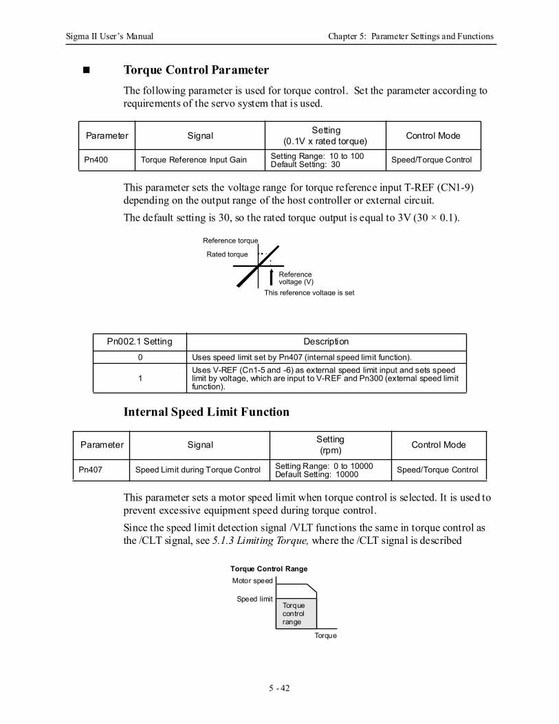
Sigma II User’s Manual Chapter 5: Parameter Settings and Functions
5 - 42
Torque Control Parameter The following parameter is used for torque control. Set the parameter according to requirements of the servo system that is used.
This parameter sets the voltage range for torque reference input T-REF (CN1-9) depending on the output range of the host controller or external circuit. The default setting is 30, so the rated torque output is equal to 3V (30 × 0.1).
Internal Speed Limit Function
This parameter sets a motor speed limit when torque control is selected. It is used to prevent excessive equipment speed during torque control. Since the speed limit detection signal /VLT functions the same in torque control as the /CLT signal, see 5.1.3 Limiting Torque, where the /CLT signal is described
Parameter Signal Setting(0.1V x rated torque) Control Mode
Pn400 Torque Reference Input Gain Setting Range: 10 to 100Default Setting: 30 Speed/Torque Control
Pn002.1 Setting Description0 Uses speed limit set by Pn407 (internal speed limit function).
1Uses V-REF (Cn1-5 and -6) as external speed limit input and sets speed limit by voltage, which are input to V-REF and Pn300 (external speed limit function).
Parameter Signal Setting(rpm) Control Mode
Pn407 Speed Limit during Torque Control Setting Range: 0 to 10000Default Setting: 10000 Speed/Torque Control
Reference voltage (V)
Reference torque
This reference voltage is set
Rated torque
Torquecontrolrange
Torque
Motor speed
Speed limit
Torque Control Range
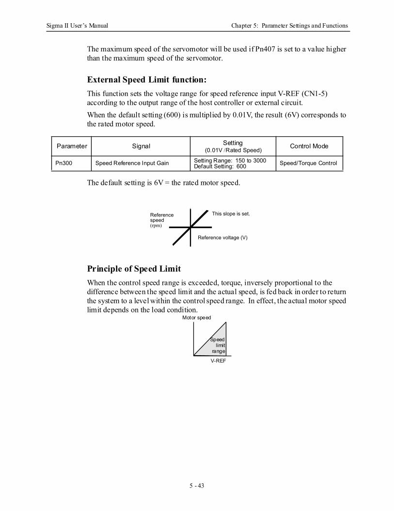
Sigma II User’s Manual Chapter 5: Parameter Settings and Functions
5 - 43
The maximum speed of the servomotor will be used if Pn407 is set to a value higher than the maximum speed of the servomotor.
External Speed Limit function: This function sets the voltage range for speed reference input V-REF (CN1-5) according to the output range of the host controller or external circuit. When the default setting (600) is multiplied by 0.01V, the result (6V) corresponds to the rated motor speed.
The default setting is 6V = the rated motor speed.
Principle of Speed Limit When the control speed range is exceeded, torque, inversely proportional to the difference between the speed limit and the actual speed, is fed back in order to return the system to a level within the control speed range. In effect, the actual motor speed limit depends on the load condition.
Parameter Signal Setting(0.01V /Rated Speed) Control Mode
Pn300 Speed Reference Input Gain Setting Range: 150 to 3000Default Setting: 600 Speed/Torque Control
Reference voltage (V)
Reference speed (rpm)
This slope is set.
Speedlimit
range
Motor speed
V-REF
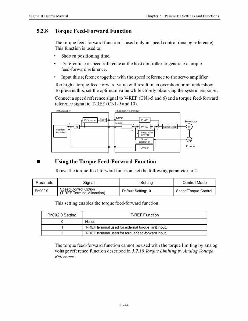
Sigma II User’s Manual Chapter 5: Parameter Settings and Functions
5 - 44
5.2.8 Torque Feed-Forward Function
The torque feed-forward function is used only in speed control (analog reference). This function is used to:• Shorten positioning time.• Differentiate a speed reference at the host controller to generate a torque
feed-forward reference.• Input this reference together with the speed reference to the servo amplifier. Too high a torque feed-forward value will result in an overshoot or an undershoot. To prevent this, set the optimum value while closely observing the system response. Connect a speed reference signal to V-REF (CN1-5 and 6) and a torque feed-forward reference signal to T-REF (CN1-9 and 10).
Using the Torque Feed-Forward Function To use the torque feed-forward function, set the following parameter to 2.
This setting enables the torque feed-forward function.
The torque feed-forward function cannot be used with the torque limiting by analog voltage reference function described in 5.2.10 Torque Limiting by Analog Voltage Reference.
Parameter Signal Setting Control Mode
Pn002.0 Speed Control Option (T-REF Terminal Allocation) Default Setting: 0 Speed/Torque Control
Pn002.0 Setting T-REF Function0 None.1 T-REF terminal used for external torque limit input. 2 T-REF terminal used for torque feed-forward input.
Current loop
Integration
Servomotor
Encoder
M
PG
(Pn101)
Speedcalcula tion
Divider
KFFDifferentia l
KpPosition
Reference
T-REF
V-REF
Host controller SGDH Servo ampl ifier
+ ++ +
+
-
+
-
Pn400
Pn100
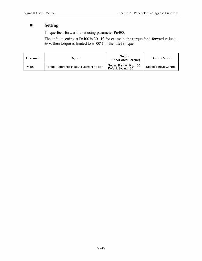
Sigma II User’s Manual Chapter 5: Parameter Settings and Functions
5 - 45
SettingTorque feed-forward is set using parameter Pn400. The default setting at Pn400 is 30. If, for example, the torque feed-forward value is ±3V, then torque is limited to ±100% of the rated torque.
Parameter Signal Setting(0.1V/Rated Torque) Control Mode
Pn400 Torque Reference Input Adjustment Factor Setting Range: 0 to 100Default Setting: 30 Speed/Torque Control
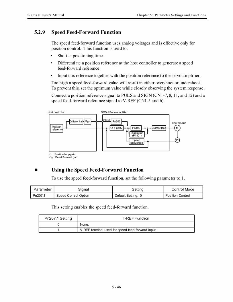
Sigma II User’s Manual Chapter 5: Parameter Settings and Functions
5 - 46
5.2.9 Speed Feed-Forward Function
The speed feed-forward function uses analog voltages and is effective only for position control. This function is used to:• Shorten positioning time.• Differentiate a position reference at the host controller to generate a speed
feed-forward reference.• Input this reference together with the position reference to the servo amplifier. Too high a speed feed-forward value will result in either overshoot or undershoot. To prevent this, set the optimum value while closely observing the system response. Connect a position reference signal to PULS and SIGN (CN1-7, 8, 11, and 12) and a speed feed-forward reference signal to V-REF (CN1-5 and 6).
Using the Speed Feed-Forward Function To use the speed feed-forward function, set the following parameter to 1.
This setting enables the speed feed-forward function.
Parameter Signal Setting Control ModePn207.1 Speed Control Option Default Setting: 0 Position Control
Pn207.1 Setting T-REF Function0 None.1 V-REF terminal used for speed feed-forward input.
Positionreference
V-REF
Kp (Pn102)
Differential KFF Pn300
SGDH Servo amplifierHost controller
Integration
Pn100
(Pn101)
Speedcalculation
Current loop
PG
M
Servomotor
Kp: Position loop gainKFF : Feed-Forward gain

Sigma II User’s Manual Chapter 5: Parameter Settings and Functions
5 - 47
Setting Speed feed-forward is set using parameter Pn300. The default setting at Pn300 is 600. If, for example, the speed feed-forward value is ±6V, then speed is limited to ±100% of the rated torque.
Parameter Signal Setting(0.01V/Rated Speed) Control Mode
Pn300 Speed Reference Input Adjustment Factor
Setting Range: 150 to 3000Default Setting: 600 Position Control
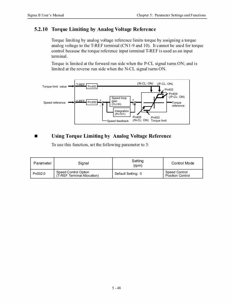
Sigma II User’s Manual Chapter 5: Parameter Settings and Functions
5 - 48
5.2.10 Torque Limiting by Analog Voltage Reference
Torque limiting by analog voltage reference limits torque by assigning a torque analog voltage to the T-REF terminal (CN1-9 and 10). It cannot be used for torque control because the torque reference input terminal T-REF is used as an input terminal. Torque is limited at the forward run side when the P-CL signal turns ON; and is limited at the reverse run side when the N-CL signal turns ON.
Using Torque Limiting by Analog Voltage ReferenceTo use this function, set the following parameter to 3:
Parameter Signal Setting(rpm) Control Mode
Pn002.0 Speed Control Option (T-REF Terminal Allocation) Default Setting: 0 Speed Control
Position Control
Pn300
Integration (Pn101)
Speed loop gain (Pn100)
++
+
-
Speed feedback
Pn400Torque limit value
Speed reference
T-REF
V-REF Torque reference
Pn403 Torque limit
Pn404 (/P-CL: ON)
Pn402
Pn405 (/N-CL: ON)
(/P-CL: ON)(/N-CL: ON)
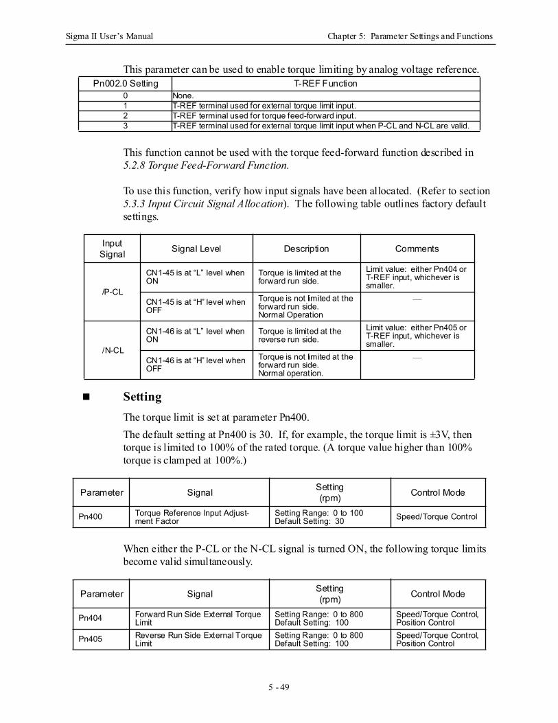
Sigma II User’s Manual Chapter 5: Parameter Settings and Functions
5 - 49
This parameter can be used to enable torque limiting by analog voltage reference.
This function cannot be used with the torque feed-forward function described in 5.2.8 Torque Feed-Forward Function.
To use this function, verify how input signals have been allocated. (Refer to section 5.3.3 Input Circuit Signal Allocation). The following table outlines factory default settings.
SettingThe torque limit is set at parameter Pn400. The default setting at Pn400 is 30. If, for example, the torque limit is ±3V, then torque is limited to 100% of the rated torque. (A torque value higher than 100% torque is clamped at 100%.)
When either the P-CL or the N-CL signal is turned ON, the following torque limits become valid simultaneously.
Pn002.0 Setting T-REF Function0 None.1 T-REF terminal used for external torque limit input. 2 T-REF terminal used for torque feed-forward input. 3 T-REF terminal used for external torque limit input when P-CL and N-CL are valid.
Input Signal Signal Level Description Comments
/P-CL
CN1-45 is at “L” level when ON
Torque is limited at the forward run side.
Limit value: either Pn404 or T-REF input, whichever is smaller.
CN1-45 is at “H” level when OFF
Torque is not limited at the forward run side.Normal Operation
—
/N-CL
CN1-46 is at “L” level when ON
Torque is limited at the reverse run side.
Limit value: either Pn405 or T-REF input, whichever is smaller.
CN1-46 is at “H” level when OFF
Torque is not limited at the forward run side.Normal operation.
—
Parameter Signal Setting(rpm) Control Mode
Pn400 Torque Reference Input Adjust-ment Factor
Setting Range: 0 to 100Default Setting: 30 Speed/Torque Control
Parameter Signal Setting(rpm) Control Mode
Pn404 Forward Run Side External Torque Limit
Setting Range: 0 to 800Default Setting: 100
Speed/Torque Control,Position Control
Pn405 Reverse Run Side External Torque Limit
Setting Range: 0 to 800Default Setting: 100
Speed/Torque Control,Position Control
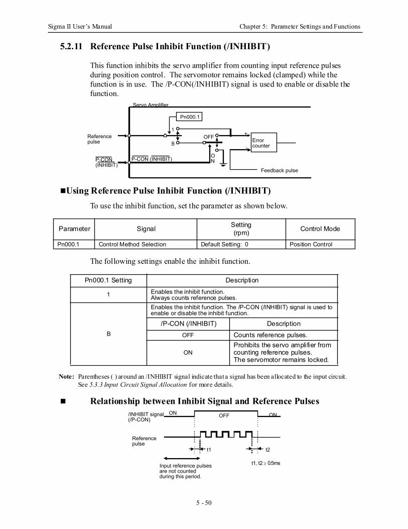
Sigma II User’s Manual Chapter 5: Parameter Settings and Functions
5 - 50
5.2.11 Reference Pulse Inhibit Function (/INHIBIT)
This function inhibits the servo amplifier from counting input reference pulses during position control. The servomotor remains locked (clamped) while the function is in use. The /P-CON(/INHIBIT) signal is used to enable or disable the function.
Using Reference Pulse Inhibit Function (/INHIBIT) To use the inhibit function, set the parameter as shown below.
The following settings enable the inhibit function.
Note: Parentheses ( ) around an /INHIBIT signal indicate that a signal has been allocated to the input circuit. See 5.3.3 Input Circuit Signal Allocation for more details.
Relationship between Inhibit Signal and Reference Pulses
Parameter Signal Setting(rpm) Control Mode
Pn000.1 Control Method Selection Default Setting: 0 Position Control
Pn000.1 Setting Description
1 Enables the inhibit function. Always counts reference pulses.
B
Enables the inhibit function. The /P-CON (/INHIBIT) signal is used to enable or disable the inhibit function.
/P-CON (/INHIBIT) DescriptionOFF Counts reference pulses.
ONProhibits the servo amplifier from counting reference pulses. The servomotor remains locked.
Pn000.1
Error counter
Reference pulse
1
BOFF
ON
+
-
Feedback pulse
Servo Amplifier
P-CON (INHIBIT)P-CON (INHIBIT)
ON
Reference pulse
OFF
t1
ON
t2
Input reference pulses are not counted during this period.
/INHIBIT signal (/P-CON)
t1, t2 ≥ 0.5ms
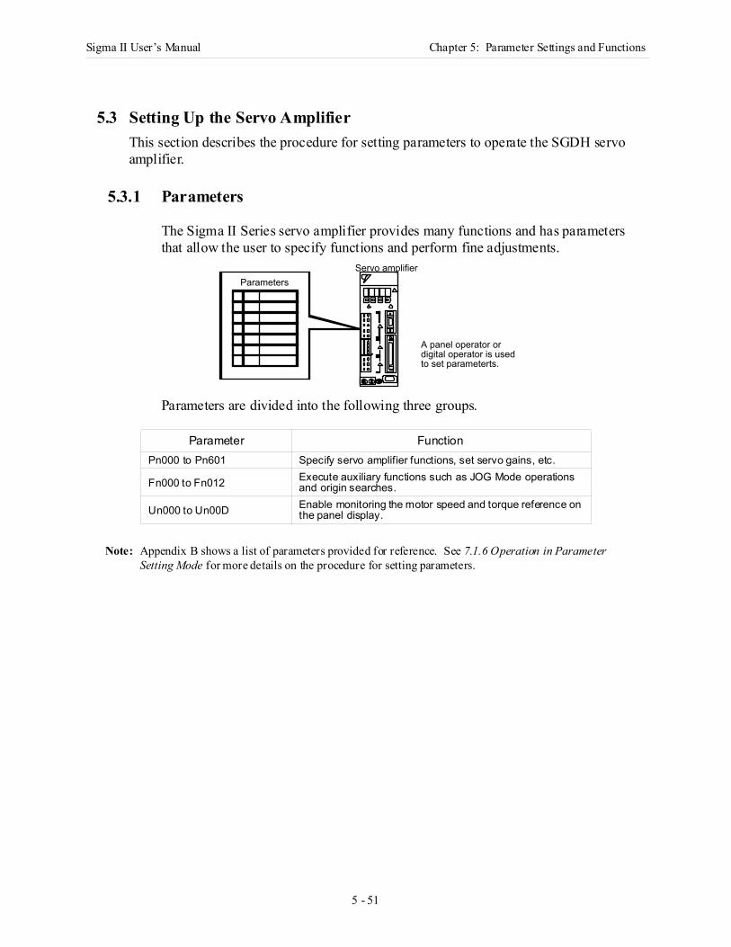
Sigma II User’s Manual Chapter 5: Parameter Settings and Functions
5 - 51
5 Pa rame te r Settings and Functions
5.3 Setting Up the Servo AmplifierThis section describes the procedure for setting parameters to operate the SGDH servo amplifier.
5.3.1 Parameters
The Sigma IΙ Series servo amplifier provides many functions and has parameters that allow the user to specify functions and perform fine adjustments.
Parameters are divided into the following three groups.
Note: Appendix B shows a list of parameters provided for reference. See 7.1.6 Operation in Parameter Setting Mode for more details on the procedure for setting parameters.
Parameter FunctionPn000 to Pn601 Specify servo amplifier functions, set servo gains, etc.
Fn000 to Fn012 Execute auxiliary functions such as JOG Mode operations and origin searches.
Un000 to Un00D Enable monitoring the motor speed and torque reference on the panel display.
Servo amplifierParameters
A panel operator ordigital operator is usedto set parameterts.
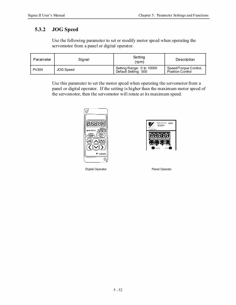
Sigma II User’s Manual Chapter 5: Parameter Settings and Functions
5 - 52
5.3.2 JOG Speed
Use the following parameter to set or modify motor speed when operating the servomotor from a panel or digital operator.
Use this parameter to set the motor speed when operating the servomotor from a panel or digital operator. If the setting is higher than the maximum motor speed of the servomotor, then the servomotor will rotate at its maximum speed.
Parameter Signal Setting(rpm) Description
Pn304 JOG Speed Setting Range: 0 to 10000Default Setting: 500
Speed/Torque Control, Position Control
Digital Operator
SGDH-
MODE/SET DATA/
CHARGE POWER
SERVOPACK 200V
YASKAWA
Panel Operato
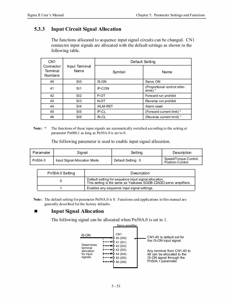
Sigma II User’s Manual Chapter 5: Parameter Settings and Functions
5 - 53
5.3.3 Input Circuit Signal Allocation
The functions allocated to sequence input signal circuits can be changed. CN1 connector input signals are allocated with the default settings as shown in the following table.
Note: * The functions of these input signals are automatically switched according to the setting at parameter Pn000.1 as long as Pn50A.0 is set to 0.
The following parameter is used to enable input signal allocation.
Note: The default setting for parameter Pn50A.0 is 0. Functions and applications in this manual are generally described for the factory defaults.
Input Signal Allocation The following signal can be allocated when Pn50A.0 is set to 1.
CN1 Connector Terminal Numbers
Input Terminal Name
Default Setting
Symbol Name
40 SI0 /S-ON Servo ON
41 SI1 /P-CON (Proportional control refer-ence) *
42 SI2 P-OT Forward run prohibit 43 SI3 N-OT Reverse run prohibit 44 SI4 /ALM-RST Alarm reset 45 SI5 /P-CL (Forward current limit) *46 SI6 /N-CL (Reverse current limit) *
Parameter Signal Setting Description
Pn50A.0 Input Signal Allocation Mode Default Setting: 0 Speed/Torque Control, Position Control
Pn50A.0 Setting Description
0 Default setting for sequence input signal allocation.This setting is the same as Yaskawa SGDB- AD servo amplifiers.
1 Enables any sequence input signal settings.
40 (SI0)41 (SI1)42 (SI2)43 (SI3)44 (SI4)45 (SI5)46 (SI6)
Servo amplifier
CN1
Determines terminal allocation for input signals.
/S-ON CN1-40 is default set forthe /S-ON input signal.
Any terminal from CN1-40 to46 can be allocated to the/S-ON signal through thePn50A.1 parameter.
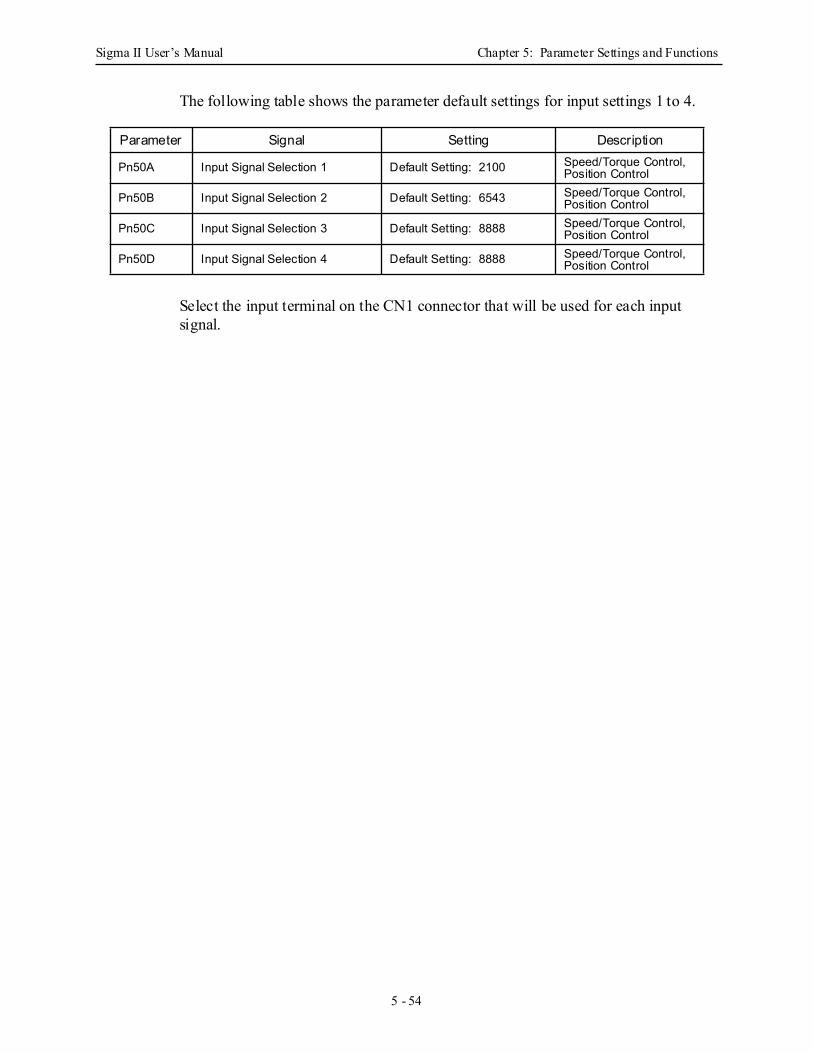
Sigma II User’s Manual Chapter 5: Parameter Settings and Functions
5 - 54
The following table shows the parameter default settings for input settings 1 to 4.
Select the input terminal on the CN1 connector that will be used for each input signal.
Parameter Signal Setting Description
Pn50A Input Signal Selection 1 Default Setting: 2100 Speed/Torque Control, Position Control
Pn50B Input Signal Selection 2 Default Setting: 6543 Speed/Torque Control, Position Control
Pn50C Input Signal Selection 3 Default Setting: 8888 Speed/Torque Control, Position Control
Pn50D Input Signal Selection 4 Default Setting: 8888 Speed/Torque Control, Position Control
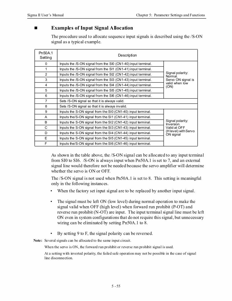
Sigma II User’s Manual Chapter 5: Parameter Settings and Functions
5 - 55
Examples of Input Signal Allocation The procedure used to allocate sequence input signals is described using the /S-ON signal as a typical example.
As shown in the table above, the /S-ON signal can be allocated to any input terminal from SI0 to SI6. /S-ON is always input when Pn50A.1 is set to 7, and an external signal line would therefore not be needed because the servo amplifier will determine whether the servo is ON or OFF.The /S-ON signal is not used when Pn50A.1 is set to 8. This setting is meaningful only in the following instances.• When the factory set input signal are to be replaced by another input signal.
• The signal must be left ON (low level) during normal operation to make the signal valid when OFF (high level) when forward run prohibit (P-OT) and reverse run prohibit (N-OT) are input. The input terminal signal line must be left ON even in system configurations that do not require this signal, but unnecessary wiring can be eliminated by setting Pn50A.1 to 8.
• By setting 9 to F, the signal polarity can be reversed.Note: Several signals can be allocated to the same input circuit.
When the servo is ON, the forward run prohibit or reverse run prohibit signal is used.
At a setting with inverted polarity, the failed safe operation may not be possible in the case of signal line disconnection.
Pn50A.1Setting Description
0 Inputs the /S-ON signal from the SI0 (CN1-40) input terminal.
Signal polarity: Normal.Servo ON signal is valid when low (ON)
1 Inputs the /S-ON signal from the SI1 (CN1-41) input terminal.2 Inputs the /S-ON signal from the SI2 (CN1-42) input terminal.3 Inputs the /S-ON signal from the SI3 (CN1-43) input terminal.4 Inputs the /S-ON signal from the SI4 (CN1-44) input terminal.5 Inputs the /S-ON signal from the SI5 (CN1-45) input terminal.6 Inputs the /S-ON signal from the SI6 (CN1-46) input terminal.7 Sets /S-ON signal so that it is always valid. 8 Sets /S-ON signal so that it is always invalid. 9 Inputs the S-ON signal from the SI0 (CN1-40) input terminal.
Signal polarity: Inversion.Valid at OFF(H level) with Servo ON signal
A Inputs the/S-ON signal from the SI1 (CN1-41) input terminal.B Inputs the S-ON signal from the SI2 (CN1-42) input terminal.C Inputs the S-ON signal from the SI3 (CN1-43) input terminal.D Inputs the S-ON signal from the SI4 (CN1-44) input terminal.E Inputs the S-ON signal from the SI5 (CN1-45) input terminal.F Inputs the/S-ON signal from the SI6 (CN1-46) input terminal.
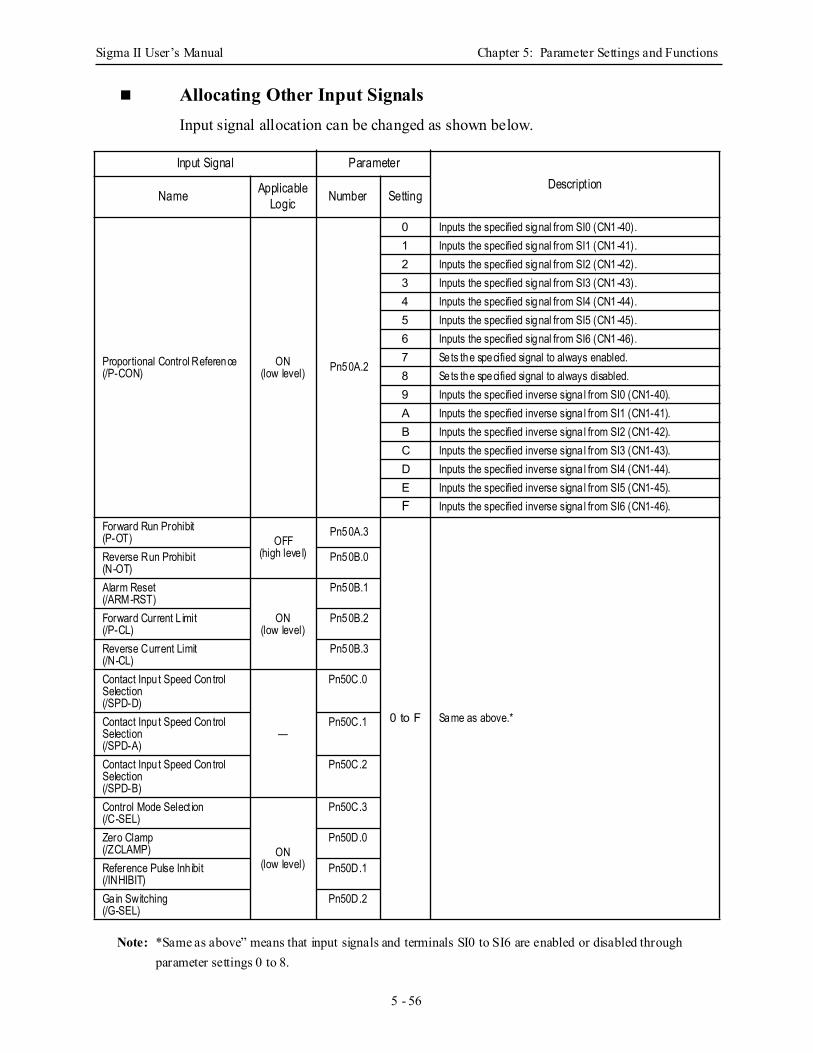
Sigma II User’s Manual Chapter 5: Parameter Settings and Functions
5 - 56
Allocating Other Input Signals Input signal allocation can be changed as shown below.
Note: *Same as above” means that input signals and terminals SI0 to SI6 are enabled or disabled through parameter settings 0 to 8.
Input Signal ParameterDescript ion
Name Applicable Logic Number Setting
Proportional Control Reference(/P-CON)
ON(low level) Pn50A.2
0 Inputs the specified signal from SI0 (CN1-40).1 Inputs the specified signal from SI1 (CN1-41).2 Inputs the specified signal from SI2 (CN1-42).3 Inputs the specified signal from SI3 (CN1-43).4 Inputs the specified signal from SI4 (CN1-44).5 Inputs the specified signal from SI5 (CN1-45).6 Inputs the specified signal from SI6 (CN1-46).7 Sets the specified signal to always enabled. 8 Sets the specified signal to always disabled. 9 Inputs the specified inverse signa l from SI0 (CN1-40).A Inputs the specified inverse signa l from SI1 (CN1-41).B Inputs the specified inverse signa l from SI2 (CN1-42).C Inputs the specified inverse signa l from SI3 (CN1-43).D Inputs the specified inverse signa l from SI4 (CN1-44).E Inputs the specified inverse signa l from SI5 (CN1-45).F Inputs the specified inverse signa l from SI6 (CN1-46).
Forward Run Prohibit(P-OT) OFF
(high leve l)
Pn50A.3
0 to F Same as above.*
Reverse Run Prohibit(N-OT)
Pn50B.0
Alarm Reset(/ARM-RST)
ON(low level)
Pn50B.1
Forward Current L imit(/P-CL)
Pn50B.2
Reverse Current Limit(/N-CL)
Pn50B.3
Contact Inpu t Speed Control Selection(/SPD-D)
—
Pn50C.0
Contact Inpu t Speed Control Selection(/SPD-A)
Pn50C.1
Contact Inpu t Speed Control Selection(/SPD-B)
Pn50C.2
Control Mode Select ion(/C-SEL)
ON(low level)
Pn50C.3
Zero Clamp(/ZCLAMP)
Pn50D.0
Reference Pulse Inh ibit(/INHIBIT)
Pn50D.1
Gain Switching(/G-SEL)
Pn50D.2
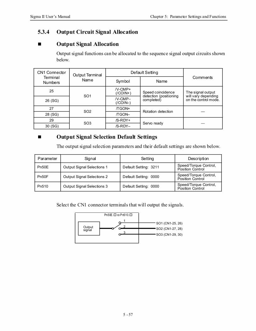
Sigma II User’s Manual Chapter 5: Parameter Settings and Functions
5 - 57
5.3.4 Output Circuit Signal Allocation
Output Signal Allocation Output signal functions can be allocated to the sequence signal output circuits shown below.
Output Signal Selection Default Settings The output signal selection parameters and their default settings are shown below.
Select the CN1 connector terminals that will output the signals.
CN1 Connector Terminal Numbers
Output Terminal Name
Default SettingComments
Symbol Name
25SO1
/V-CMP+(/COIN+) Speed coincidence
detection (positioning completed)
The signal output will vary depending on the control mode. 26 (SG) /V-CMP–
(/COIN–)27
SO2/TGON+
Rotation detection —28 (SG) /TGON–
29SO3
/S-RDY+Servo ready —
30 (SG) /S-RDY–
Parameter Signal Setting Description
Pn50E Output Signal Selections 1 Default Setting: 3211 Speed/Torque Control, Position Control
Pn50F Output Signal Selections 2 Default Setting: 0000 Speed/Torque Control, Position Control
Pn510 Output Signal Selections 3 Default Setting: 0000 Speed/Torque Control, Position Control
Output signal
1
2
3
SO1 (CN1-25, 26)SO2 (CN1-27, 28)
SO3 (CN1-29, 30)
Pn50E. to Pn510.
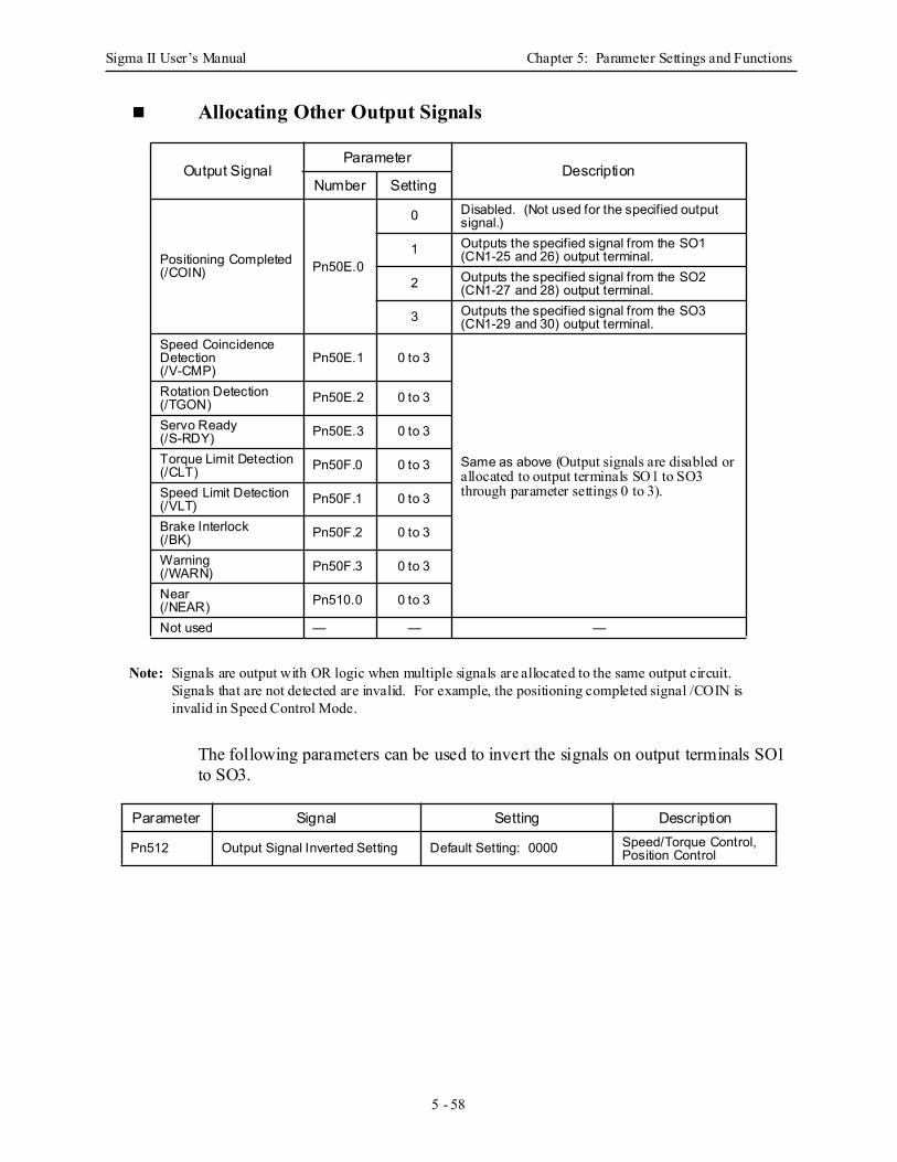
Sigma II User’s Manual Chapter 5: Parameter Settings and Functions
5 - 58
Allocating Other Output Signals
Note: Signals are output with OR logic when multiple signals are allocated to the same output circuit. Signals that are not detected are invalid. For example, the positioning completed signal /COIN is invalid in Speed Control Mode.
The following parameters can be used to invert the signals on output terminals SO1 to SO3.
Output SignalParameter
DescriptionNumber Setting
Positioning Completed(/COIN) Pn50E.0
0 Disabled. (Not used for the specified output signal.)
1 Outputs the specified signal from the SO1 (CN1-25 and 26) output terminal.
2 Outputs the specified signal from the SO2 (CN1-27 and 28) output terminal.
3 Outputs the specified signal from the SO3 (CN1-29 and 30) output terminal.
Speed Coincidence Detection(/V-CMP)
Pn50E.1 0 to 3
Same as above (Output signals are disabled or allocated to output terminals SO1 to SO3 through parameter settings 0 to 3).
Rotation Detection(/TGON) Pn50E.2 0 to 3
Servo Ready(/S-RDY) Pn50E.3 0 to 3
Torque Limit Detection(/CLT) Pn50F.0 0 to 3
Speed Limit Detection(/VLT) Pn50F.1 0 to 3
Brake Interlock(/BK) Pn50F.2 0 to 3
Warning(/WARN) Pn50F.3 0 to 3
Near(/NEAR) Pn510.0 0 to 3
Not used — — —
Parameter Signal Setting Description
Pn512 Output Signal Inverted Setting Default Setting: 0000 Speed/Torque Control, Position Control
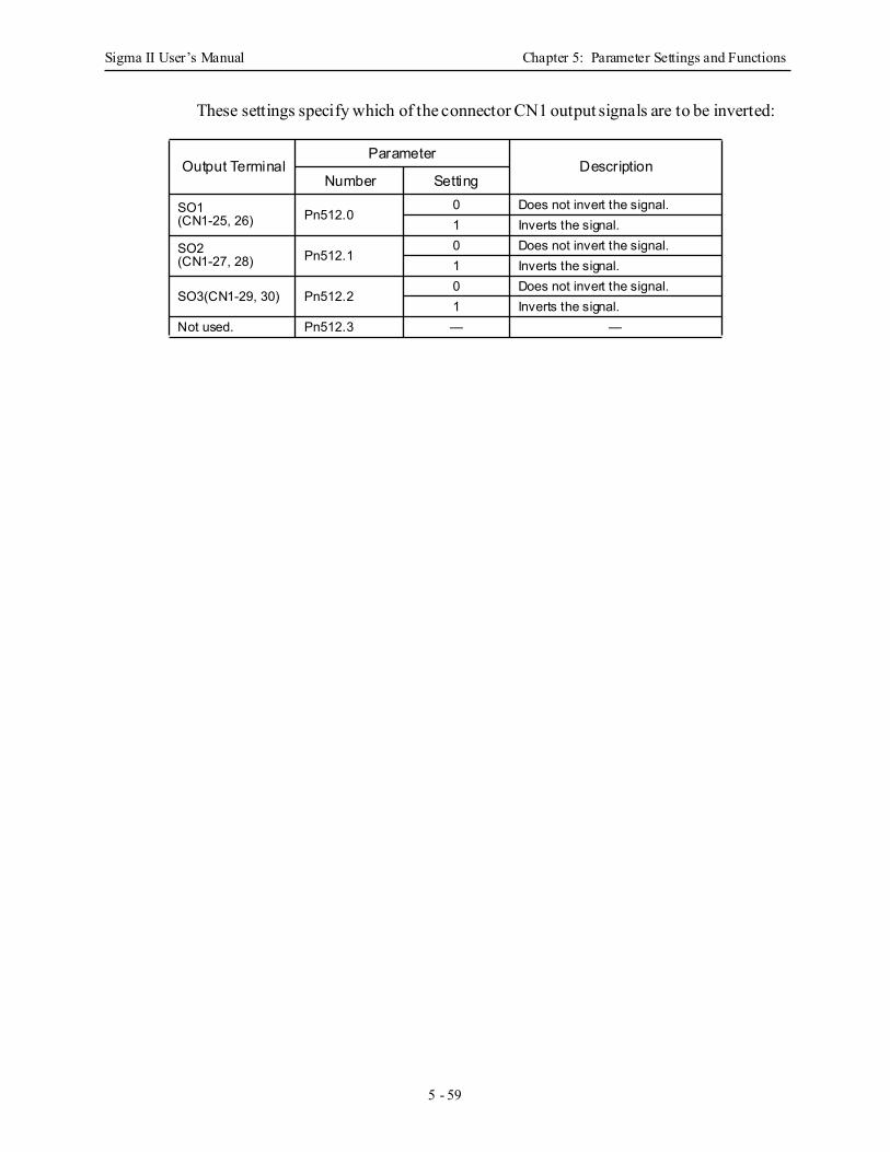
Sigma II User’s Manual Chapter 5: Parameter Settings and Functions
5 - 59
These settings specify which of the connector CN1 output signals are to be inverted:
Output TerminalParameter
DescriptionNumber Setting
SO1(CN1-25, 26) Pn512.0
0 Does not invert the signal.1 Inverts the signal.
SO2(CN1-27, 28) Pn512.1
0 Does not invert the signal.1 Inverts the signal.
SO3(CN1-29, 30) Pn512.20 Does not invert the signal.1 Inverts the signal.
Not used. Pn512.3 — —
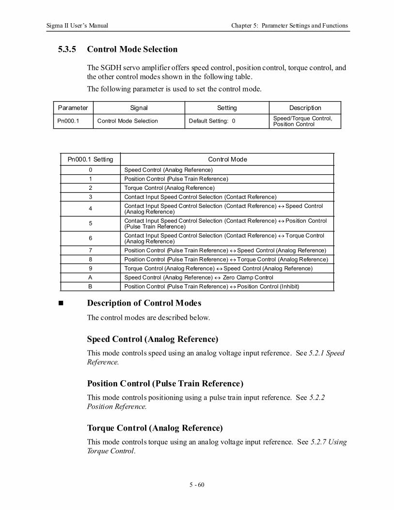
Sigma II User’s Manual Chapter 5: Parameter Settings and Functions
5 - 60
5.3.5 Control Mode Selection
The SGDH servo amplifier offers speed control, position control, torque control, and the other control modes shown in the following table. The following parameter is used to set the control mode.
Description of Control Modes The control modes are described below.
Speed Control (Analog Reference) This mode controls speed using an analog voltage input reference. See 5.2.1 Speed Reference.
Position Control (Pulse Train Reference) This mode controls positioning using a pulse train input reference. See 5.2.2 Position Reference.
Torque Control (Analog Reference) This mode controls torque using an analog voltage input reference. See 5.2.7 Using Torque Control.
Parameter Signal Setting Description
Pn000.1 Control Mode Selection Default Setting: 0 Speed/Torque Control, Position Control
Pn000.1 Setting Control Mode0 Speed Control (Analog Reference)1 Position Control (Pulse Train Reference)2 Torque Control (Analog Reference)3 Contact Input Speed Control Selection (Contact Reference)
4 Contact Input Speed Control Selection (Contact Reference) ↔ Speed Control (Analog Reference)
5 Contact Input Speed Control Selection (Contact Reference) ↔ Position Control (Pulse Train Reference)
6 Contact Input Speed Control Selection (Contact Reference) ↔ Torque Control (Analog Reference)
7 Position Control (Pulse Train Reference) ↔ Speed Control (Analog Reference)8 Position Control (Pulse Train Reference) ↔ Torque Control (Analog Reference)9 Torque Control (Analog Reference) ↔ Speed Control (Analog Reference)A Speed Control (Analog Reference) ↔ Zero Clamp ControlB Position Control (Pulse Train Reference) ↔ Position Control (Inhibit)
Sigma II User’s Manual Chapter 5: Parameter Settings and Functions
5 - 61
Contact Input Speed Control Selection (Contact Reference) This mode uses the /P-CON (/SPD-D), /P-CL (/SPD-A), and /N-CL (/SPD-B) input signals to control speed as it switches among the three preset operating speeds in the servo amplifier. See 5.2.6 Contact Input Speed Control.
Contact Input Speed Control Selection (Contact Reference) ↔ Speed Control (Analog Reference) This mode controls speed by switching between contact reference and analog voltage reference speed control. Analog voltage reference speed control is enabled when both /P-CL (/SPD-A) and /N-CL (/SPD-B) input signals are OFF (high level). See 5.2.6 Contact Input Speed Control.
Contact Input Speed Control Selection (Contact Reference) ↔ Position Control (Pulse Train Reference) This mode switches between contact reference speed control and pulse train reference position control. Pulse train reference position control is enabled when both /P-CL (/SPD-A) and /N-CL (/SPD-B) input signals are OFF (high level). See 5.2.6 Contact Input Speed Control.
Contact Input Speed Control Selection (Contact Reference) ↔ Torque Control (Analog Reference) This mode switches between contact reference speed control and analog voltage reference torque control. Torque control using an analog voltage reference is enabled when both /P-CL (/SPD–A) and /N-CL (/SPD-B) input signals are OFF (high level). See 5.2.6 Contact Input Speed Control.
Position Control (Pulse Train Reference) ↔ Speed Control (Analog Reference) This mode switches between position and speed control through the /P-CON (/C-SEL) signal.
Position Control (Pulse Train Reference) ↔ Torque Control (Analog Reference) This mode switches between position and torque control through the /P-CON (/C-SEL) signal.
Sigma II User’s Manual Chapter 5: Parameter Settings and Functions
5 - 62
Torque Control (Analog Reference) ↔ Speed Control (Analog Reference) This mode switches between torque and speed control through the /P-CON (/C-SEL) signal. See 5.2.7 Using Torque Control.
Speed Control (Analog Reference) ↔ Zero Clamp This speed control mode is used to set the zero clamp function when the servo amplifier is stopped. Zero clamp operates when the /P-CON (/ZCLAMP) signal is ON (low level). See 5.4.3 Using the Zero Clamp Function.
Position Control (Pulse Train Reference) ↔ Position Control (Inhibit) This mode controls positioning by inhibiting reference pulse input through the /P-CON (/INHIBIT) signal. See 5.2.11 Reference Pulse Inhibit Function (INHIBIT)
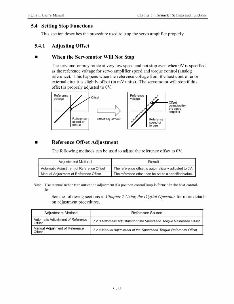
Sigma II User’s Manual Chapter 5: Parameter Settings and Functions
5 - 63
5.4 Setting Stop FunctionsThis section describes the procedure used to stop the servo amplifier properly.
5.4.1 Adjusting Offset
When the Servomotor Will Not StopThe servomotor may rotate at very low speed and not stop even when 0V is specified as the reference voltage for servo amplifier speed and torque control (analog reference). This happens when the reference voltage from the host controller or external circuit is slightly offset (in mV units). The servomotor will stop if this offset is properly adjusted to 0V.
Reference Offset Adjustment The following methods can be used to adjust the reference offset to 0V.
Note: Use manual rather than automatic adjustment if a position control loop is formed in the host control-ler.
See the following sections in Chapter 7 Using the Digital Operator for more details on adjustment procedures.
Adjustment Method ResultAutomatic Adjustment of Reference Offset The reference offset is automatically adjusted to 0V. Manual Adjustment of Reference Offset The reference offset can be set to a specified value.
Adjustment Method Reference SourceAutomatic Adjustment of Reference Offset 7.2.3 Automatic Adjustment of the Speed and Torque Reference Offset
Manual Adjustment of Reference Offset 7.2.4 Manual Adjustment of the Speed and Torque Reference Offset
Offset
Offset adjustment
Referencevoltage
Referencevoltage
Referencespeed ortorque
Referencespeed ortorque
Offsetcorrected bythe servo amplifier
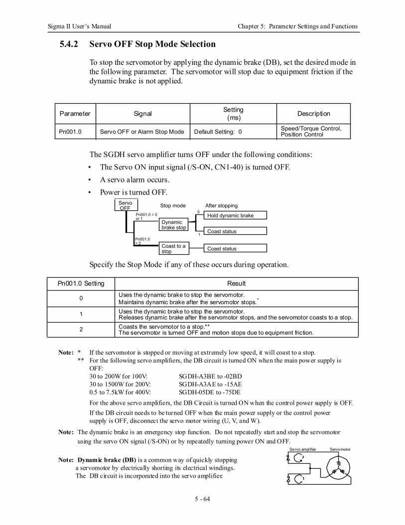
Sigma II User’s Manual Chapter 5: Parameter Settings and Functions
5 - 64
5.4.2 Servo OFF Stop Mode Selection
To stop the servomotor by applying the dynamic brake (DB), set the desired mode in the following parameter. The servomotor will stop due to equipment friction if the dynamic brake is not applied.
The SGDH servo amplifier turns OFF under the following conditions: • The Servo ON input signal (/S-ON, CN1-40) is turned OFF.• A servo alarm occurs. • Power is turned OFF.
Specify the Stop Mode if any of these occurs during operation.
Note: * If the servomotor is stopped or moving at extremely low speed, it will coast to a stop. ** For the following servo amplifiers, the DB circuit is turned ON when the main power supply is
OFF:30 to 200W for 100V: SGDH-A3BE to -02BD30 to 1500W for 200V: SGDH-A3AE to -15AE0.5 to 7.5kW for 400V: SGDH-05DE to -75DEFor the above servo amplifiers, the DB Circuit is turned ON when the control power supply is OFF.If the DB circuit needs to be turned OFF when the main power supply or the control power supply is OFF, disconnect the servo motor wiring (U, V, and W).
Note: The dynamic brake is an emergency stop function. Do not repeatedly start and stop the servomotor using the servo ON signal (/S-ON) or by repeatedly turning power ON and OFF.
Parameter Signal Setting(ms) Description
Pn001.0 Servo OFF or Alarm Stop Mode Default Setting: 0 Speed/Torque Control, Position Control
Pn001.0 Setting Result
0 Uses the dynamic brake to stop the servomotor. Maintains dynamic brake after the servomotor stops.*
1 Uses the dynamic brake to stop the servomotor. Releases dynamic brake after the servomotor stops, and the servomotor coasts to a stop.
2 Coasts the servomotor to a stop.**The servomotor is turned OFF and motion stops due to equipment friction.
Stop mode After stopping
Coast to a stop
Dynamic brake stop
Hold dynamic brake
Coast status
0
1
Pn001.0 = 0 or 1
Servo OFF
Pn001.0 = 2
Coast status
Servo ampl ifier Servomotor
Note: Dynamic brake (DB) is a common way of quickly stopping a servomotor by electrically shorting its electrical windings. The DB circuit is incorporated into the servo amplifier.
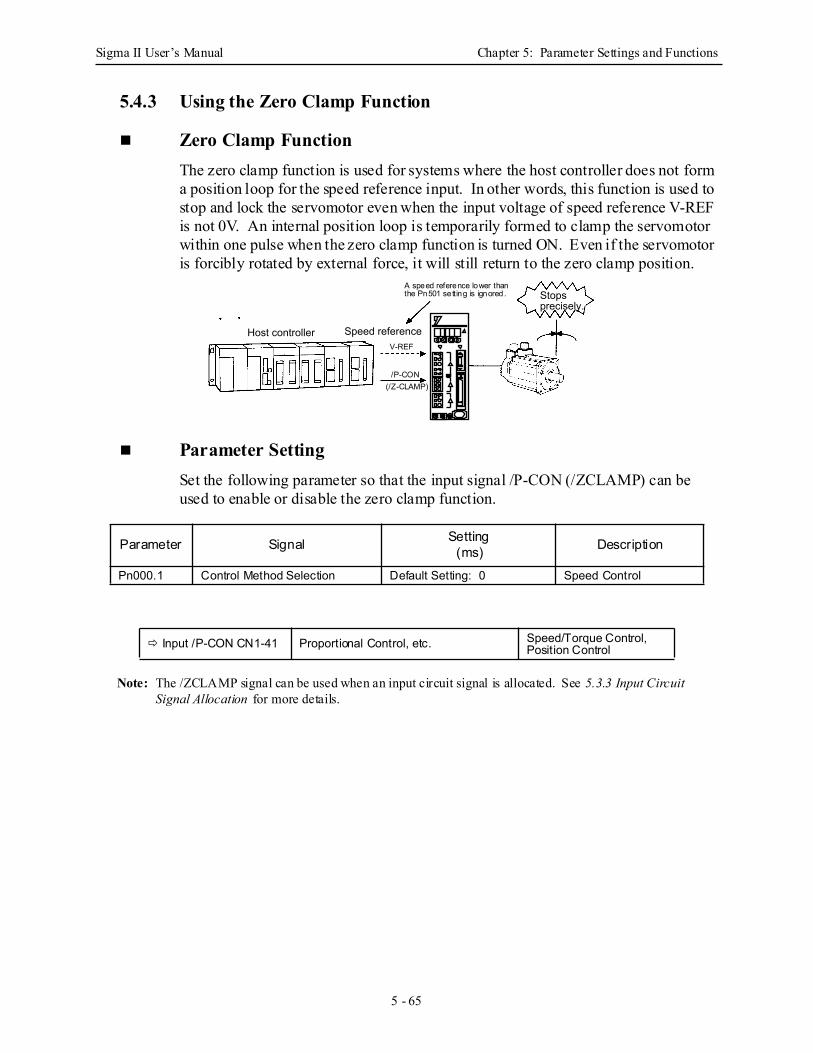
Sigma II User’s Manual Chapter 5: Parameter Settings and Functions
5 - 65
5.4.3 Using the Zero Clamp Function
Zero Clamp Function The zero clamp function is used for systems where the host controller does not form a position loop for the speed reference input. In other words, this function is used to stop and lock the servomotor even when the input voltage of speed reference V-REF is not 0V. An internal position loop is temporarily formed to clamp the servomotor within one pulse when the zero clamp function is turned ON. Even if the servomotor is forcibly rotated by external force, it will still return to the zero clamp position.
Parameter SettingSet the following parameter so that the input signal /P-CON (/ZCLAMP) can be used to enable or disable the zero clamp function.
Note: The /ZCLAMP signal can be used when an input circuit signal is allocated. See 5.3.3 Input Circuit Signal Allocation for more details.
Parameter Signal Setting(ms) Description
Pn000.1 Control Method Selection Default Setting: 0 Speed Control
Input /P-CON CN1-41 Proportional Control, etc. Speed/Torque Control, Position Control
Host controller Speed reference
Stops precisely.
V-REF
/P-CON(/Z-CLAMP)
A speed reference lower thanthe Pn501 setting is ignored.
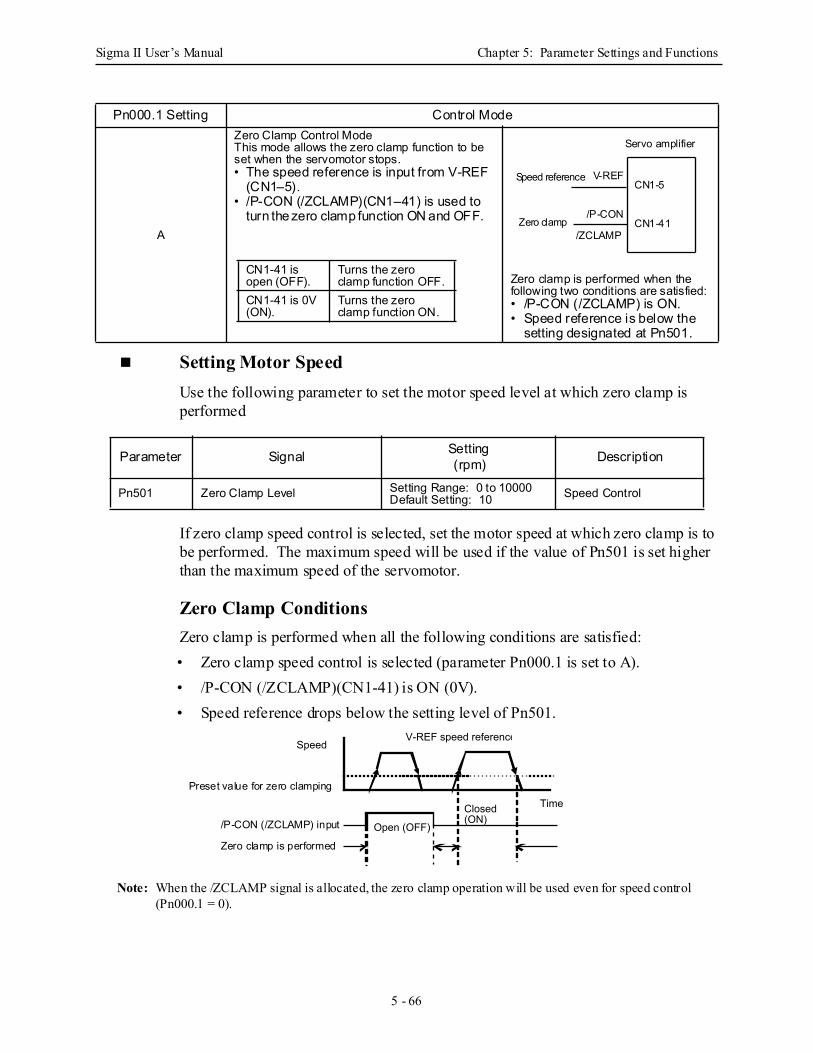
Sigma II User’s Manual Chapter 5: Parameter Settings and Functions
5 - 66
Setting Motor Speed Use the following parameter to set the motor speed level at which zero clamp is performed
If zero clamp speed control is selected, set the motor speed at which zero clamp is to be performed. The maximum speed will be used if the value of Pn501 is set higher than the maximum speed of the servomotor.
Zero Clamp Conditions Zero clamp is performed when all the following conditions are satisfied: • Zero clamp speed control is selected (parameter Pn000.1 is set to A). • /P-CON (/ZCLAMP)(CN1-41) is ON (0V). • Speed reference drops below the setting level of Pn501.
Note: When the /ZCLAMP signal is allocated, the zero clamp operation will be used even for speed control (Pn000.1 = 0).
Pn000.1 Setting Control Mode
A
Zero Clamp Control ModeThis mode allows the zero clamp function to be set when the servomotor stops. • The speed reference is input from V-REF
(CN1–5). • /P-CON (/ZCLAMP)(CN1–41) is used to
turn the zero clamp function ON and OFF.
Zero clamp is performed when the following two conditions are satisfied:• /P-CON (/ZCLAMP) is ON.• Speed reference is below the
setting designated at Pn501.
Parameter Signal Setting(rpm) Description
Pn501 Zero Clamp Level Setting Range: 0 to 10000Default Setting: 10 Speed Control
CN1-41 is open (OFF).
Turns the zero clamp function OFF.
CN1-41 is 0V (ON).
Turns the zero clamp function ON.
Servo amplifier
Speed reference
Zero clamp
V-REF
/P-CON
/ZCLAMP
CN1-5
CN1-41
V-REF speed referenceSpeed
Open (OFF)
Closed (ON)
TimePreset value for zero clamping
/P-CON (/ZCLAMP) input
Zero clamp is performed

Sigma II User’s Manual Chapter 5: Parameter Settings and Functions
5 - 67
5.4.4 Using the Holding Brake
The holding brake is used when a servodrive controls a vertical axis. In other words, a servomotor with brake prevents the movable part from shifting due to the force of gravity when system power goes OFF.
Note: The brake built into the servomotor SGM H with brakes is a de-energization brake, which is used only to hold and cannot be used for braking. Use the holding brake only to hold a stopped motor. Brake torque is at least 120% of the rated motor torque.
Wiring Example Use the servo amplifier contact output signal /BK and the brake power supply to form a brake ON/OFF circuit. The following diagram shows a standard wiring example.
*CN1-†1 /BK+ and CN1-†2 /BK- are the output terminals allocated at parameter Pn50F.2.
This output signal controls the brake when using a servomotor with a brake and does
Output /BK Brake Interlock Output Speed/Torque Control, Position Control
Servomoto
Prevents the movable part from shifting due to gravity when system power goes OFF.
Holding brake
M
BK
PG
Servomotor with brake
A (1)B (2)C (3)
D (4)E (5)
F (6)
UVW
CN2
Red
Black
Blue or yellow
White AC DC
BK-RY
BK-RY
+24V
Brake Power Supply
Power supply
Servo amplifier
L1L2L3L1CL2CCN1-†1
CN1-†2
/BK+*
/BK-*
Brake power supplies are availablein 200V and 100V models.
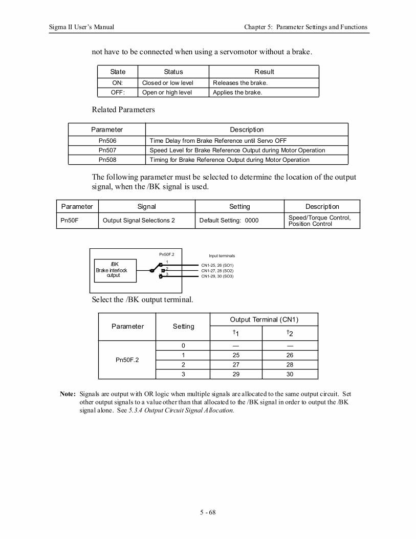
Sigma II User’s Manual Chapter 5: Parameter Settings and Functions
5 - 68
not have to be connected when using a servomotor without a brake.
Related Parameters
The following parameter must be selected to determine the location of the output signal, when the /BK signal is used.
Select the /BK output terminal.
Note: Signals are output with OR logic when multiple signals are allocated to the same output circuit. Set other output signals to a value other than that allocated to the /BK signal in order to output the /BK signal alone. See 5.3.4 Output Circuit Signal Allocation.
State Status ResultON: Closed or low level Releases the brake. OFF: Open or high level Applies the brake.
Parameter DescriptionPn506 Time Delay from Brake Reference until Servo OFF Pn507 Speed Level for Brake Reference Output during Motor Operation Pn508 Timing for Brake Reference Output during Motor Operation
Parameter Signal Setting Description
Pn50F Output Signal Selections 2 Default Setting: 0000 Speed/Torque Control, Position Control
Parameter SettingOutput Terminal (CN1)†1 †2
Pn50F.2
0 — —1 25 262 27 283 29 30
Pn50F.2
1
23
CN1-25, 26 (SO1)CN1-27, 28 (SO2)CN1-29, 30 (SO3)
Input terminals
/BKBrake interlock
output
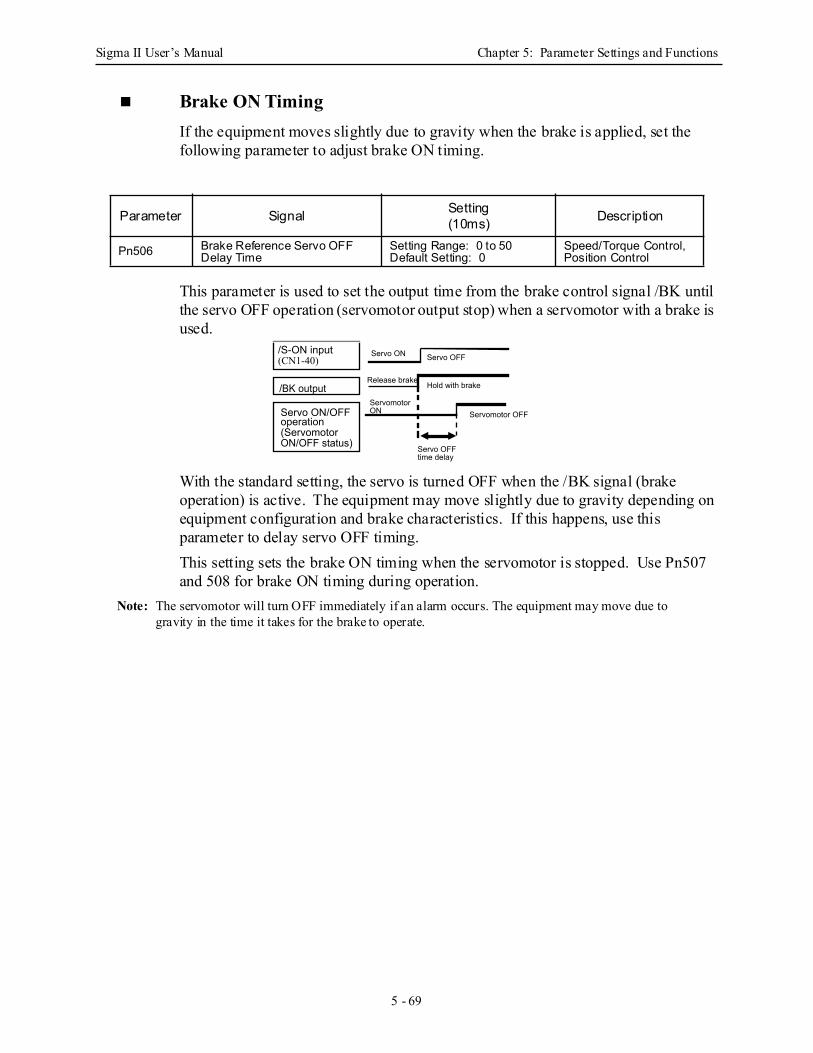
Sigma II User’s Manual Chapter 5: Parameter Settings and Functions
5 - 69
Brake ON Timing If the equipment moves slightly due to gravity when the brake is applied, set the following parameter to adjust brake ON timing.
This parameter is used to set the output time from the brake control signal /BK until the servo OFF operation (servomotor output stop) when a servomotor with a brake is used.
With the standard setting, the servo is turned OFF when the /BK signal (brake operation) is active. The equipment may move slightly due to gravity depending on equipment configuration and brake characteristics. If this happens, use this parameter to delay servo OFF timing. This setting sets the brake ON timing when the servomotor is stopped. Use Pn507 and 508 for brake ON timing during operation.
Note: The servomotor will turn OFF immediately if an alarm occurs. The equipment may move due to gravity in the time it takes for the brake to operate.
Parameter Signal Setting(10ms) Description
Pn506 Brake Reference Servo OFF Delay Time
Setting Range: 0 to 50Default Setting: 0
Speed/Torque Control, Position Control
/S-ON input (CN1-40)
/BK output
Servo ON/OFF operation (Servomotor ON/OFF status)
Release brake
Servo ON
Servomotor ON
Hold with brake
Servo OFF
Servomotor OFF
Servo OFF time delay
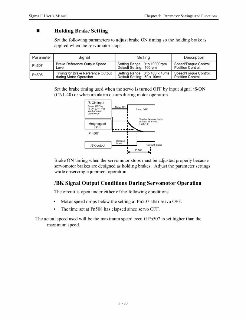
Sigma II User’s Manual Chapter 5: Parameter Settings and Functions
5 - 70
Holding Brake Setting Set the following parameters to adjust brake ON timing so the holding brake is applied when the servomotor stops.
Set the brake timing used when the servo is turned OFF by input signal /S-ON (CN1-40) or when an alarm occurs during motor operation.
Brake ON timing when the servomotor stops must be adjusted properly because servomotor brakes are designed as holding brakes. Adjust the parameter settings while observing equipment operation.
/BK Signal Output Conditions During Servomotor Operation The circuit is open under either of the following conditions:
• Motor speed drops below the setting at Pn507 after servo OFF.• The time set at Pn508 has elapsed since servo OFF.
The actual speed used will be the maximum speed even if Pn507 is set higher than the maximum speed.
Parameter Signal Setting Description
Pn507 Brake Reference Output Speed Level
Setting Range: 0 to 10000rpmDefault Setting: 100rpm
Speed/Torque Control, Position Control
Pn508 Timing for Brake Reference Output during Motor Operation
Setting Range: 0 to 100 x 10msDefault Setting: 50 x 10ms
Speed/Torque Control, Position Control
/S-ON input Power OFF by /S-ON (CN1-40) input or alarm occurrence
Motor speed (rpm)
Pn-507
/BK output
Stop by dynamic brake or coast to a stop. (Pn001.0)
Pn508
Release brake
Servo ON
Hold with brake
Servo OFF
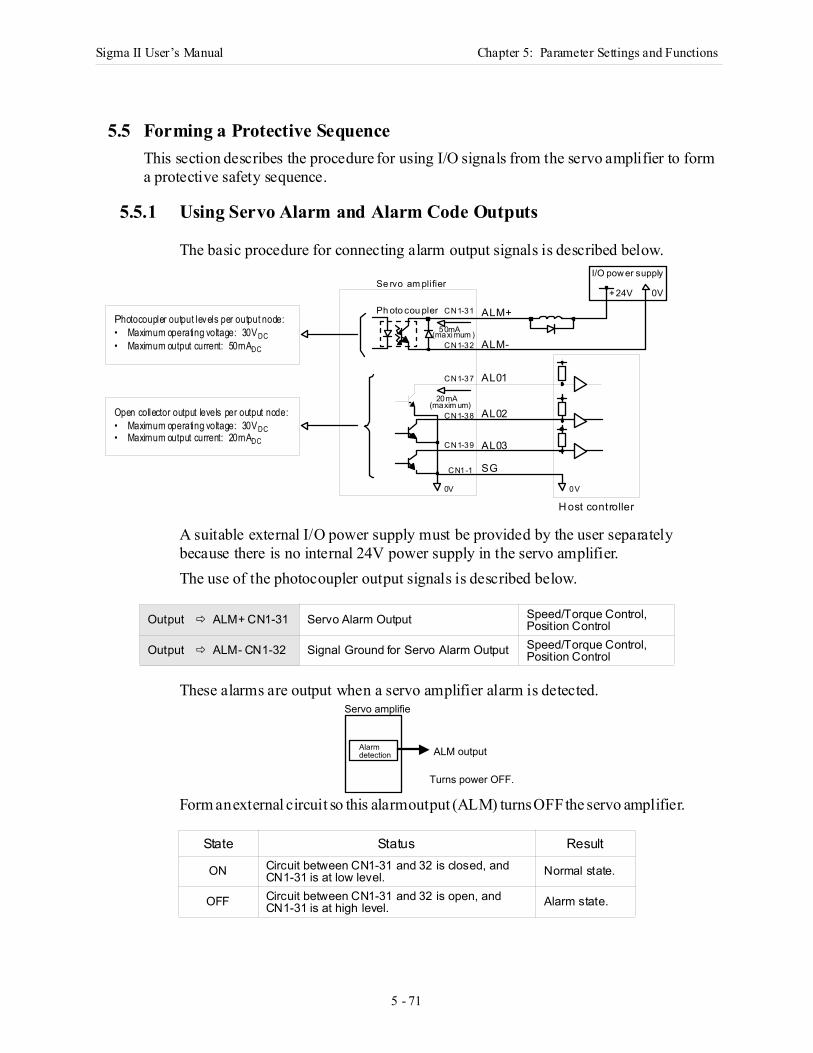
Sigma II User’s Manual Chapter 5: Parameter Settings and Functions
5 - 71
5 Pa rame te r Settings and Functions
5.5 Forming a Protective SequenceThis section describes the procedure for using I/O signals from the servo amplifier to form a protective safety sequence.
5.5.1 Using Servo Alarm and Alarm Code Outputs
The basic procedure for connecting alarm output signals is described below.
A suitable external I/O power supply must be provided by the user separately because there is no internal 24V power supply in the servo amplifier. The use of the photocoupler output signals is described below.
These alarms are output when a servo amplifier alarm is detected.
Form an external circuit so this alarm output (ALM) turns OFF the servo amplifier.
Output ALM+ CN1-31 Servo Alarm Output Speed/Torque Control,Position Control
Output ALM- CN1-32 Signal Ground for Servo Alarm Output Speed/Torque Control,Position Control
State Status Result
ON Circuit between CN1-31 and 32 is closed, and CN1-31 is at low level. Normal state.
OFF Circuit between CN1-31 and 32 is open, and CN1-31 is at high level. Alarm state.
Photocoupler output levels per output node:• Maximum operating voltage: 30VDC• Maximum output current: 50mADC
Open collector output levels per output node:• Maximum operating voltage: 30VDC• Maximum output current: 20mADC
AL01
ALM-
AL02
AL03
ALM+
SG
H ost controller
Se rvo am plifier
Ph oto cou pler CN1-31
CN1-32
CN1-37
CN1-38
CN1-39
CN1-1
0V 0V
50mA(maximum )
20mA(maxim um)
I/O power supply
+24V 0V
Turns power OFF.
Alarm detection
Servo amplifie
ALM output
Sigma II User’s Manual Chapter 5: Parameter Settings and Functions
5 - 72
Alarm codes ALO1, ALO2 and ALO3 are output to indicate each alarm type. The uses of open-collector output signals ALO1, ALO2, and ALO3 is described below.
These signals output alarm codes to indicate the type of alarm detected by the servo amplifier. Use these signals to display alarm codes at the host controller. See 9.2.3 Alarm Display Table for more on the relationship between alarm display and alarm code output. When a servo alarm (ALM) occurs, eliminate the cause of the alarm and set the following /ALM-RST input signal to high level (ON) to reset the alarm.
The alarm reset signal is used to reset a servo alarm. Form an external circuit so the servo amplifier turns OFF when an alarm occurs. Alarms are reset automatically when the control power supply is turned OFF. Alarms can also be reset using a panel or digital operator.
Note: 1. Encoder alarms cannot always be reset by inputting the /ALM-RST signal. In that case, turn thecontrol power supply OFF to reset the alarm.
2. When an alarm occurs, always eliminate the cause before resetting the alarm. See 9.2.1 Trouble-shooting Problems with Alarm Displays for more details on troubleshooting the system when analarm occurs.
Output ALO1 CN1-37 Alarm Code Output Speed/Torque Control, Position Control
Output ALO2 CN1-38 Alarm Code Output Speed/Torque Control, Position Control
Output ALO3 CN1-39 Alarm Code Output Speed/Torque Control, Position Control
Output /SG CN1-1 Signal Ground for Alarm Code Output Speed/Torque Control, Position Control
Input /ALM-RST CN1-44 Alarm Reset Speed/Torque Control, Position Control
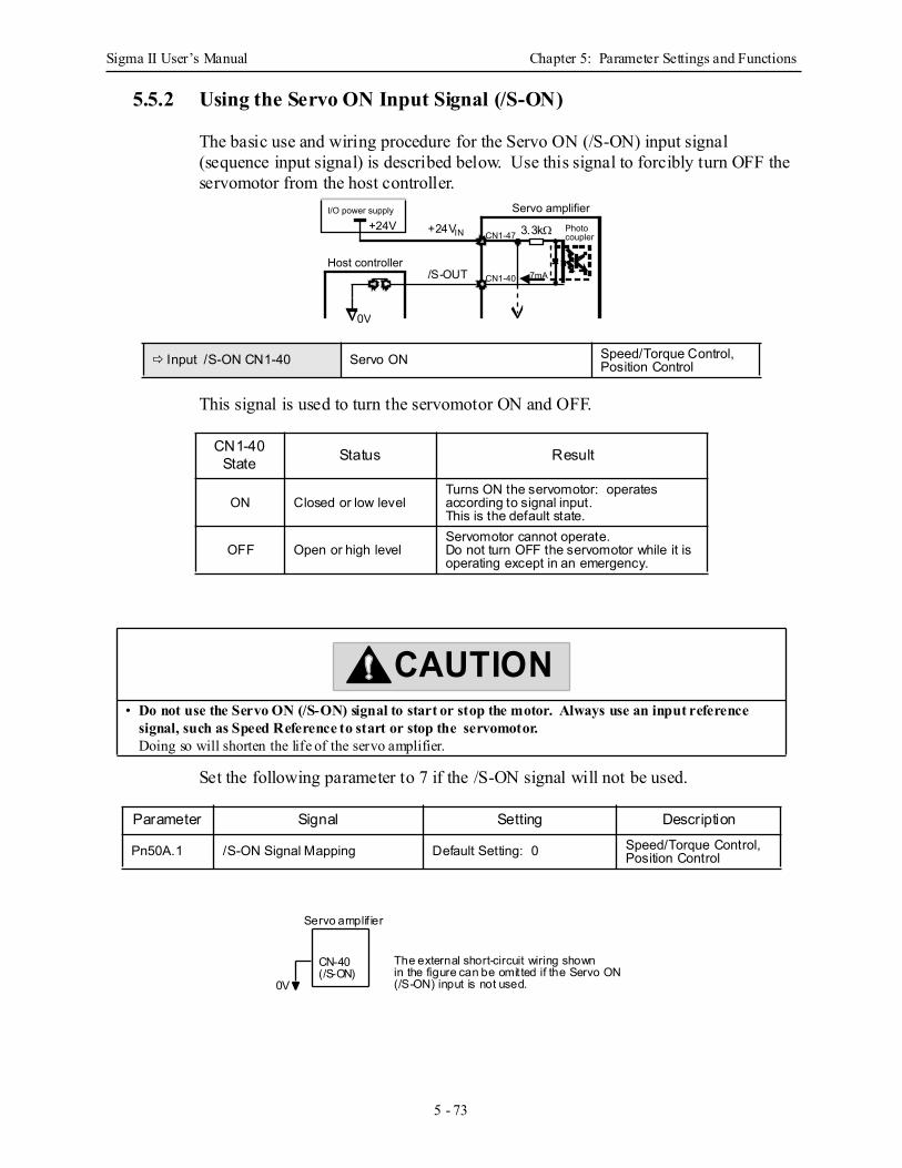
Sigma II User’s Manual Chapter 5: Parameter Settings and Functions
5 - 73
5.5.2 Using the Servo ON Input Signal (/S-ON)
The basic use and wiring procedure for the Servo ON (/S-ON) input signal (sequence input signal) is described below. Use this signal to forcibly turn OFF the servomotor from the host controller.
This signal is used to turn the servomotor ON and OFF.
Set the following parameter to 7 if the /S-ON signal will not be used.
Input /S-ON CN1-40 Servo ON Speed/Torque Control, Position Control
CN1-40State Status Result
ON Closed or low level Turns ON the servomotor: operates according to signal input.This is the default state.
OFF Open or high level Servomotor cannot operate.Do not turn OFF the servomotor while it is operating except in an emergency.
• Do not use the Servo ON (/S-ON) signal to start or stop the motor. Always use an input reference signal, such as Speed Reference to start or stop the servomotor.Doing so will shorten the life of the servo amplifier.
Parameter Signal Setting Description
Pn50A.1 /S-ON Signal Mapping Default Setting: 0 Speed/Torque Control, Position Control
+24VCN1-47
CN1-40 7mA
0V
Servo amplifierI/O power supply
Photocoupler
Host controller /S-OUT
+24VIN 3.3kΩ
CAUTION
Servo amplif ier
0V
CN-40(/S-ON)
The external short-circuit wiring shownin the figure can be omit ted if the Servo ON(/S-ON) input is not used.
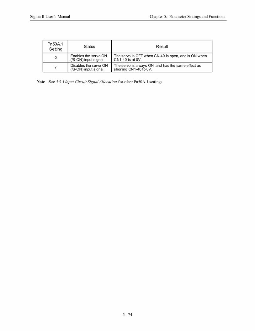
Sigma II User’s Manual Chapter 5: Parameter Settings and Functions
5 - 74
Note See 5.3.3 Input Circuit Signal Allocation for other Pn50A.1 settings.
Pn50A.1 Setting Status Result
0 Enables the servo ON (/S-ON) input signal.
The servo is OFF when CN-40 is open, and is ON when CN1-40 is at 0V.
7 Disables the servo ON (/S-ON) input signal.
The servo is always ON, and has the same effect as shorting CN1-40 to 0V.
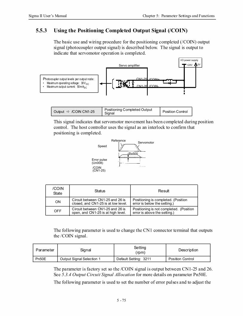
Sigma II User’s Manual Chapter 5: Parameter Settings and Functions
5 - 75
5.5.3 Using the Positioning Completed Output Signal (/COIN)
The basic use and wiring procedure for the positioning completed (/COIN) output signal (photocoupler output signal) is described below. The signal is output to indicate that servomotor operation is completed.
This signal indicates that servomotor movement has been completed during position control. The host controller uses the signal as an interlock to confirm that positioning is completed.
The following parameter is used to change the CN1 connector terminal that outputs the /COIN signal.
The parameter is factory set so the /COIN signal is output between CN1-25 and 26. See 5.3.4 Output Circuit Signal Allocation for more details on parameter Pn50E. The following parameter is used to set the number of error pulses and to adjust the
Output /COIN CN1-25 Positioning Completed Output Signal Position Control
/COINState Status Result
ON Circuit between CN1-25 and 26 is closed, and CN1-25 is at low level.
Positioning is completed. (Position error is below the setting.)
OFF Circuit between CN1-25 and 26 is open, and CN1-25 is at high level.
Positioning is not completed. (Position error is above the setting.)
Parameter Signal Setting(rpm) Description
Pn50E Output Signal Selection 1 Default Setting: 3211 Position Control
CN1-25
CN1-26
/COIN+
/COIN-
+24V 0VServo amplifier
I/O power supply
Photocoupler output levels per output node:• Maximum operating voltage: 30VDC• Maximum output current: 50mADC
Speed
Reference Servomotor
/COIN (CN1-25)
Pn500
Error pulse (Un008)
Sigma II User’s Manual Chapter 5: Parameter Settings and Functions
5 - 76
output timing of the positioning completed signal.
Note: *reference units for this parameter are the number of input pulses as defined using the electronic gear function.
This parameter is used to set output timing for the positioning completed signal (/COIN) when the position reference pulse is input and servomotor operation is completed. Set the number of error pulses in reference units. Too large a value set at this parameter may output only a small error during low-speed operation that will cause the /COIN signal to be output continuously. The positioning completed width setting has no effect on final positioning accuracy.
Note: /COIN is a position control signal. With the default setting, this signal is used for the speed coincidence output /V-CMP for speed control, and it is always ON for torque control.
Parameter Signal Setting(reference units*) Description
Pn500 Positioning Completed Width Setting Range: 0 to 250Default Setting: 7 Position Control
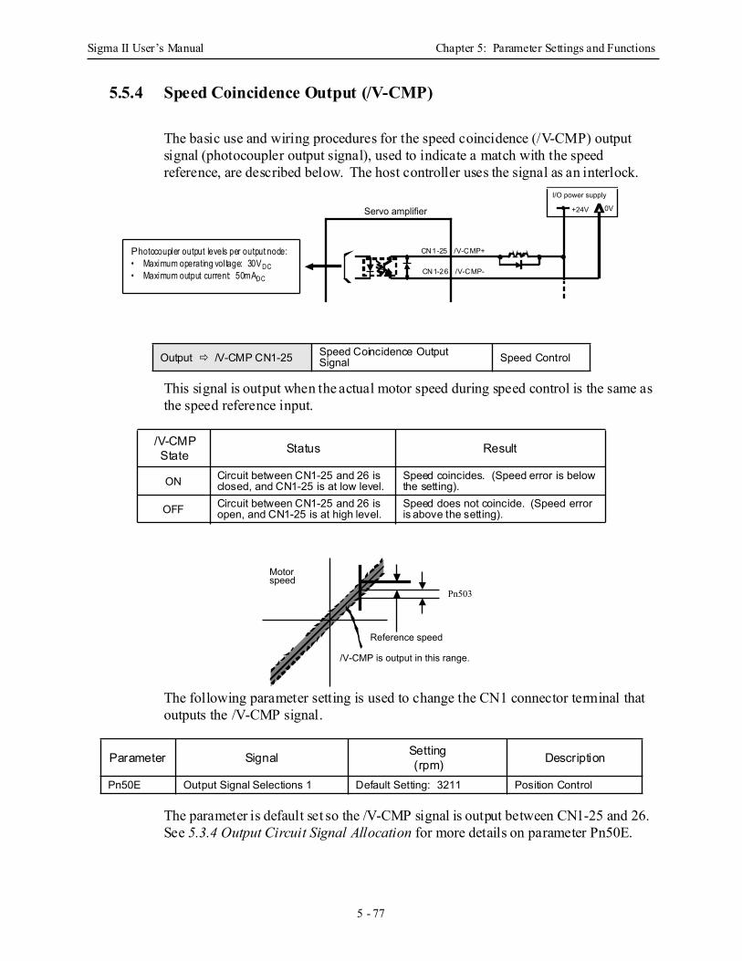
Sigma II User’s Manual Chapter 5: Parameter Settings and Functions
5 - 77
5.5.4 Speed Coincidence Output (/V-CMP)
The basic use and wiring procedures for the speed coincidence (/V-CMP) output signal (photocoupler output signal), used to indicate a match with the speed reference, are described below. The host controller uses the signal as an interlock.
This signal is output when the actual motor speed during speed control is the same as the speed reference input.
The following parameter setting is used to change the CN1 connector terminal that outputs the /V-CMP signal.
The parameter is default set so the /V-CMP signal is output between CN1-25 and 26. See 5.3.4 Output Circuit Signal Allocation for more details on parameter Pn50E.
Output /V-CMP CN1-25 Speed Coincidence Output Signal Speed Control
/V-CMPState Status Result
ON Circuit between CN1-25 and 26 is closed, and CN1-25 is at low level.
Speed coincides. (Speed error is below the setting).
OFF Circuit between CN1-25 and 26 is open, and CN1-25 is at high level.
Speed does not coincide. (Speed error is above the setting).
Parameter Signal Setting(rpm) Description
Pn50E Output Signal Selections 1 Default Setting: 3211 Position Control
+24V 0VServo amplifier
I/O power supply
Photocoupler output levels per output node:• Maximum operating voltage: 30VDC• Maximum output current: 50mADC
CN1-25 /V-CMP+
CN1-26 /V-CMP-
Motor speed
Reference speed
/V-CMP is output in this range.
Pn503
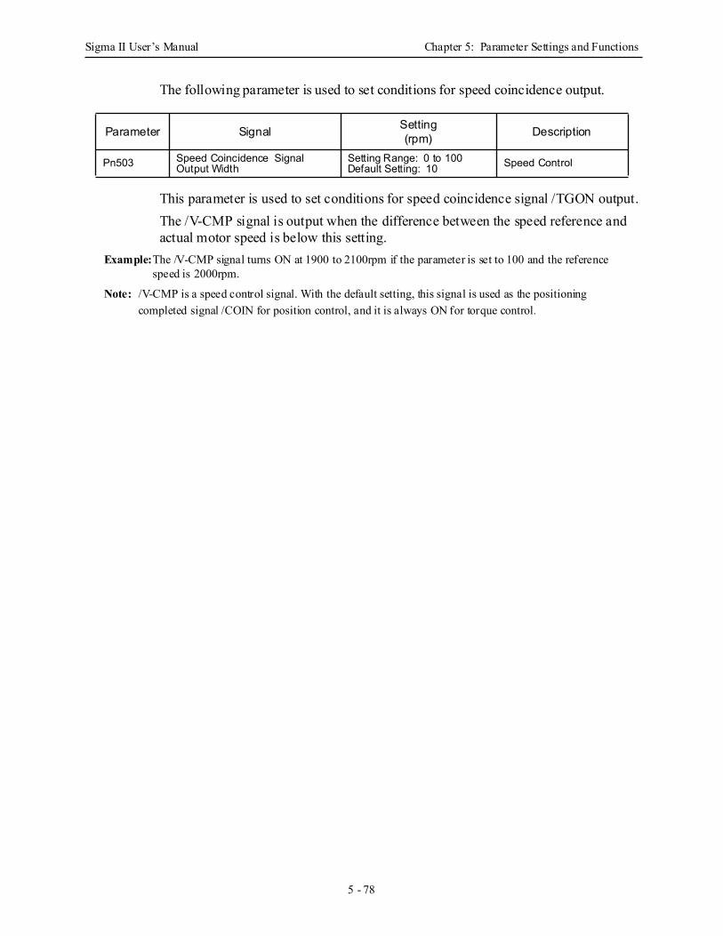
Sigma II User’s Manual Chapter 5: Parameter Settings and Functions
5 - 78
The following parameter is used to set conditions for speed coincidence output.
This parameter is used to set conditions for speed coincidence signal /TGON output.The /V-CMP signal is output when the difference between the speed reference and actual motor speed is below this setting.
Example:The /V-CMP signal turns ON at 1900 to 2100rpm if the parameter is set to 100 and the reference speed is 2000rpm.
Note: /V-CMP is a speed control signal. With the default setting, this signal is used as the positioning completed signal /COIN for position control, and it is always ON for torque control.
Parameter Signal Setting(rpm) Description
Pn503 Speed Coincidence Signal Output Width
Setting Range: 0 to 100Default Setting: 10 Speed Control
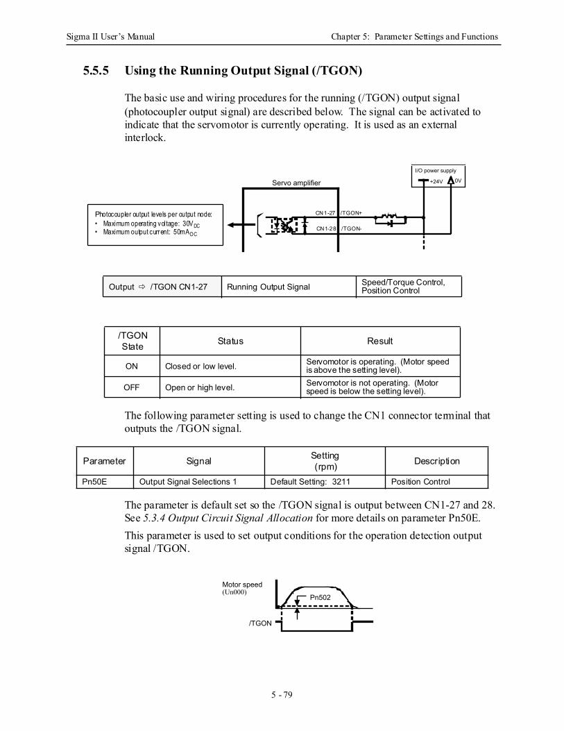
Sigma II User’s Manual Chapter 5: Parameter Settings and Functions
5 - 79
5.5.5 Using the Running Output Signal (/TGON)
The basic use and wiring procedures for the running (/TGON) output signal (photocoupler output signal) are described below. The signal can be activated to indicate that the servomotor is currently operating. It is used as an external interlock.
The following parameter setting is used to change the CN1 connector terminal that outputs the /TGON signal.
The parameter is default set so the /TGON signal is output between CN1-27 and 28. See 5.3.4 Output Circuit Signal Allocation for more details on parameter Pn50E.This parameter is used to set output conditions for the operation detection output signal /TGON.
Output /TGON CN1-27 Running Output Signal Speed/Torque Control, Position Control
/TGONState Status Result
ON Closed or low level. Servomotor is operating. (Motor speed is above the setting level).
OFF Open or high level. Servomotor is not operating. (Motor speed is below the setting level).
Parameter Signal Setting(rpm) Description
Pn50E Output Signal Selections 1 Default Setting: 3211 Position Control
+24V 0VServo amplifier
I/O power supply
CN1-27 /TGON+
CN1-28 /TGON-
Photocoupler output levels per output node:• Maximum operating voltage: 30VDC• Maximum output current: 50mADC
Motor speed (Un000)
/TGON
Pn502
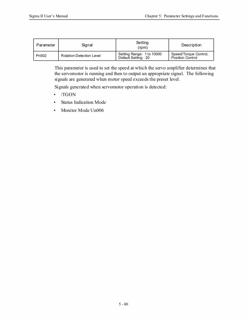
Sigma II User’s Manual Chapter 5: Parameter Settings and Functions
5 - 80
This parameter is used to set the speed at which the servo amplifier determines that the servomotor is running and then to output an appropriate signal. The following signals are generated when motor speed exceeds the preset level.Signals generated when servomotor operation is detected: • /TGON • Status Indication Mode
• Monitor Mode Un006
Parameter Signal Setting(rpm) Description
Pn502 Rotation Detection Level Setting Range: 1 to 10000Default Setting: 20
Speed/Torque Control, Position Control
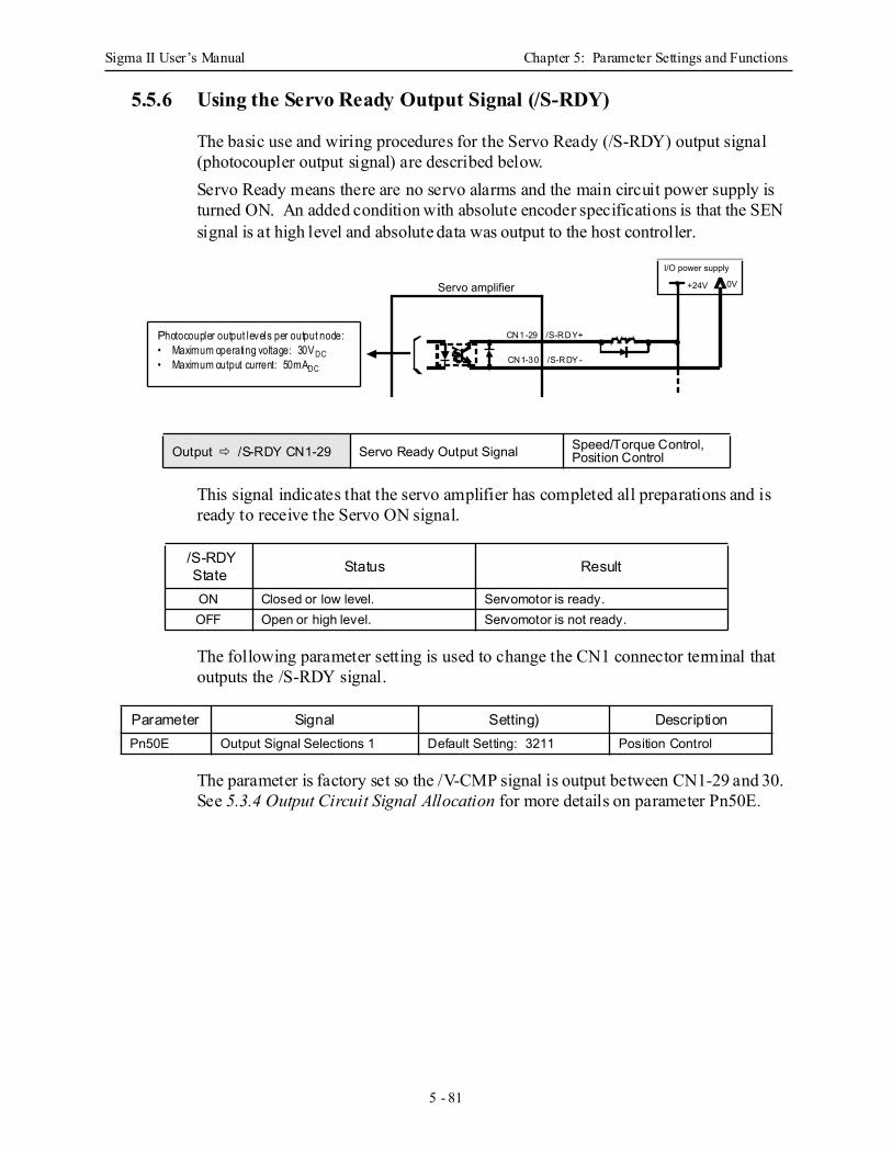
Sigma II User’s Manual Chapter 5: Parameter Settings and Functions
5 - 81
5.5.6 Using the Servo Ready Output Signal (/S-RDY)
The basic use and wiring procedures for the Servo Ready (/S-RDY) output signal (photocoupler output signal) are described below.Servo Ready means there are no servo alarms and the main circuit power supply is turned ON. An added condition with absolute encoder specifications is that the SEN signal is at high level and absolute data was output to the host controller.
This signal indicates that the servo amplifier has completed all preparations and is ready to receive the Servo ON signal.
The following parameter setting is used to change the CN1 connector terminal that outputs the /S-RDY signal.
The parameter is factory set so the /V-CMP signal is output between CN1-29 and 30. See 5.3.4 Output Circuit Signal Allocation for more details on parameter Pn50E.
Output /S-RDY CN1-29 Servo Ready Output Signal Speed/Torque Control, Position Control
/S-RDYState Status Result
ON Closed or low level. Servomotor is ready.OFF Open or high level. Servomotor is not ready.
Parameter Signal Setting) DescriptionPn50E Output Signal Selections 1 Default Setting: 3211 Position Control
+24V 0VServo amplifier
I/O power supply
CN1-29 /S-RDY+
CN1-30 /S-RDY -
Photocoupler output levels per output node:• Maximum operating voltage: 30VDC• Maximum output current: 50mADC
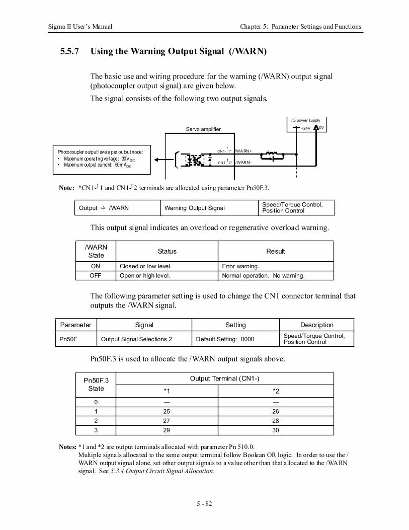
Sigma II User’s Manual Chapter 5: Parameter Settings and Functions
5 - 82
5.5.7 Using the Warning Output Signal (/WARN)
The basic use and wiring procedure for the warning (/WARN) output signal (photocoupler output signal) are given below.The signal consists of the following two output signals.
Note: *CN1-†1 and CN1-†2 terminals are allocated using parameter Pn50F.3.
This output signal indicates an overload or regenerative overload warning.
The following parameter setting is used to change the CN1 connector terminal that outputs the /WARN signal.
Pn50F.3 is used to allocate the /WARN output signals above.
Notes: *1 and *2 are output terminals allocated with parameter Pn 510.0.Multiple signals allocated to the same output terminal follow Boolean OR logic. In order to use the /WARN output signal alone, set other output signals to a value other than that allocated to the /WARN signal. See 5.3.4 Output Circuit Signal Allocation.
Output /WARN Warning Output Signal Speed/Torque Control, Position Control
/WARNState Status Result
ON Closed or low level. Error warning.OFF Open or high level. Normal operation. No warning.
Parameter Signal Setting Description
Pn50F Output Signal Selections 2 Default Setting: 0000 Speed/Torque Control, Position Control
Pn50F.3State
Output Terminal (CN1-)
*1 *20 — —1 25 262 27 283 29 30
+24V 0VServo amplifier
I/O power supply
CN1-†
1* /WA RN+
CN1-†
2* /WARN-
Photocoupler output levels per output node:• Maximum operating voltage: 30VDC• Maximum output current: 50mADC
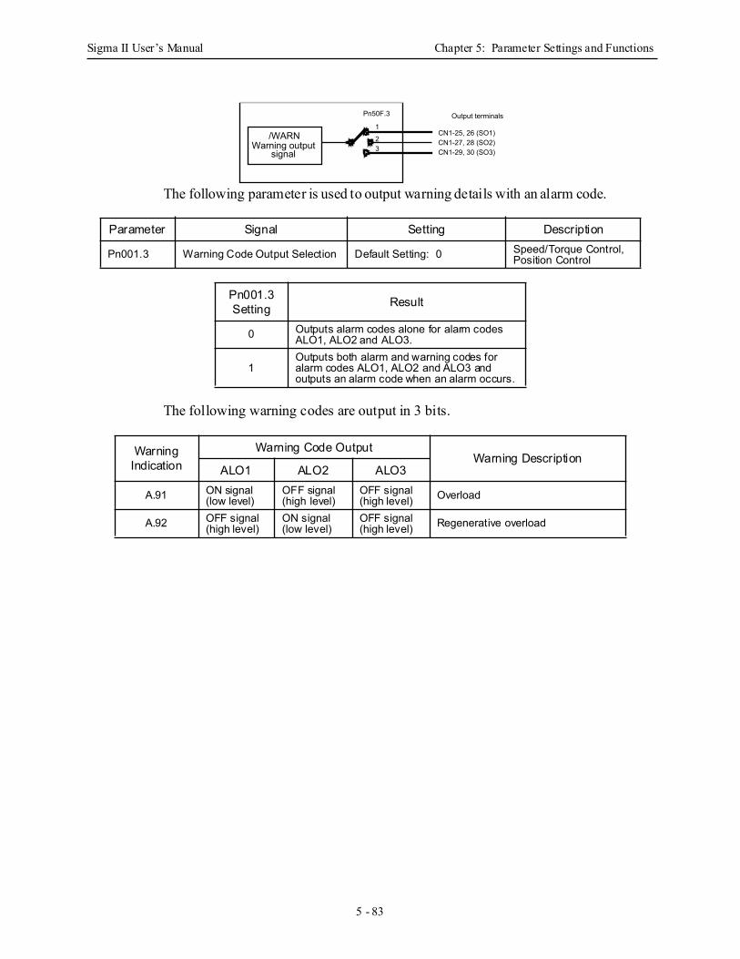
Sigma II User’s Manual Chapter 5: Parameter Settings and Functions
5 - 83
The following parameter is used to output warning details with an alarm code.
The following warning codes are output in 3 bits.
Parameter Signal Setting Description
Pn001.3 Warning Code Output Selection Default Setting: 0 Speed/Torque Control, Position Control
Pn001.3Setting Result
0 Outputs alarm codes alone for alarm codes ALO1, ALO2 and ALO3.
1Outputs both alarm and warning codes for alarm codes ALO1, ALO2 and ALO3 and outputs an alarm code when an alarm occurs.
Warning Indication
Warning Code Output Warning Description
ALO1 ALO2 ALO3
A.91 ON signal (low level)
OFF signal (high level)
OFF signal (high level) Overload
A.92 OFF signal (high level)
ON signal (low level)
OFF signal (high level) Regenerative overload
/WARNWarning output
signal
Pn50F.3
1
23
CN1-25, 26 (SO1)CN1-27, 28 (SO2)CN1-29, 30 (SO3)
Output terminals
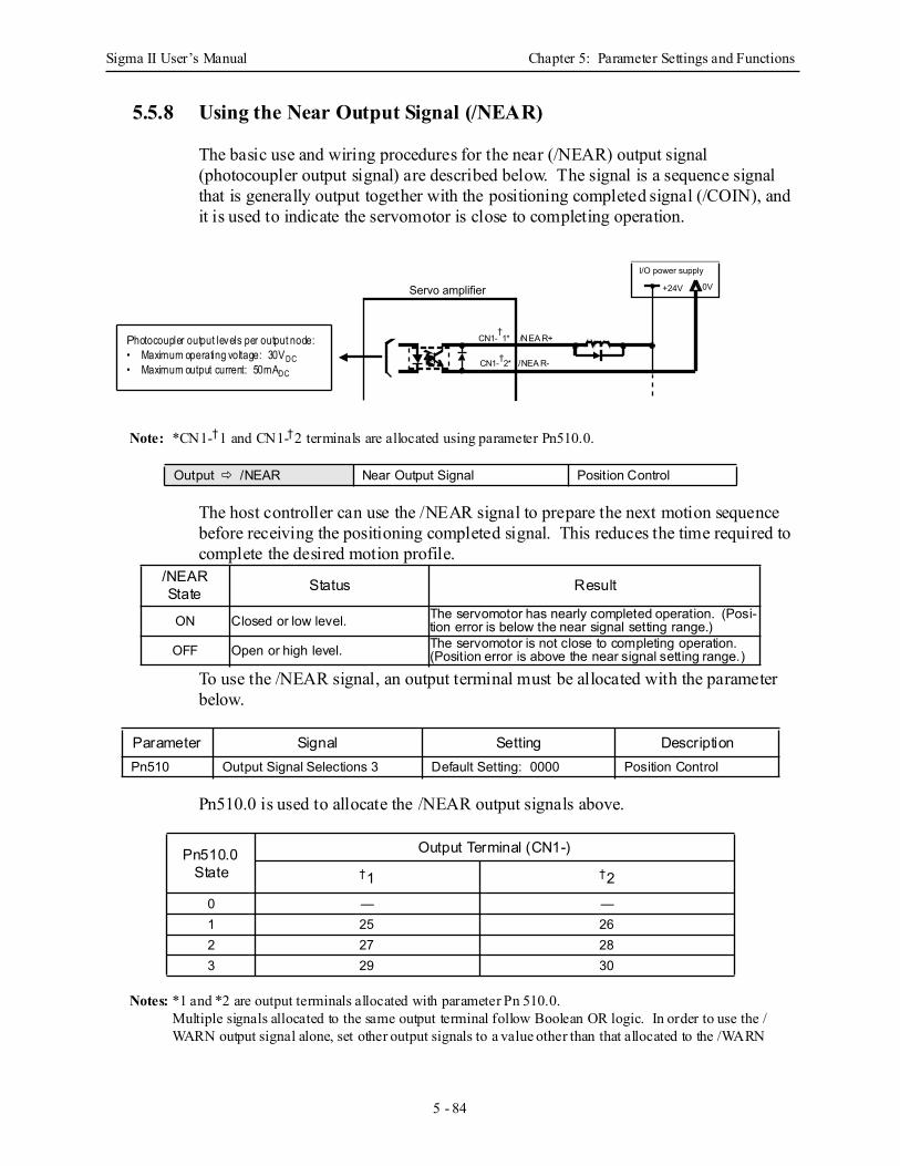
Sigma II User’s Manual Chapter 5: Parameter Settings and Functions
5 - 84
5.5.8 Using the Near Output Signal (/NEAR)
The basic use and wiring procedures for the near (/NEAR) output signal (photocoupler output signal) are described below. The signal is a sequence signal that is generally output together with the positioning completed signal (/COIN), and it is used to indicate the servomotor is close to completing operation.
Note: *CN1-†1 and CN1-†2 terminals are allocated using parameter Pn510.0.
The host controller can use the /NEAR signal to prepare the next motion sequence before receiving the positioning completed signal. This reduces the time required to complete the desired motion profile.
To use the /NEAR signal, an output terminal must be allocated with the parameter below.
Pn510.0 is used to allocate the /NEAR output signals above.
Notes: *1 and *2 are output terminals allocated with parameter Pn 510.0.Multiple signals allocated to the same output terminal follow Boolean OR logic. In order to use the /WARN output signal alone, set other output signals to a value other than that allocated to the /WARN
Output /NEAR Near Output Signal Position Control
/NEARState Status Result
ON Closed or low level. The servomotor has nearly completed operation. (Posi-tion error is below the near signal setting range.)
OFF Open or high level. The servomotor is not close to completing operation. (Position error is above the near signal setting range.)
Parameter Signal Setting DescriptionPn510 Output Signal Selections 3 Default Setting: 0000 Position Control
Pn510.0State
Output Terminal (CN1-)†1 †2
0 — —1 25 262 27 283 29 30
+24V 0VServo amplifier
I/O power supply
CN1-†1* /NEA R+
CN1-†2* /NEA R-
Photocoupler output levels per output node:• Maximum operating voltage: 30VDC• Maximum output current: 50mADC
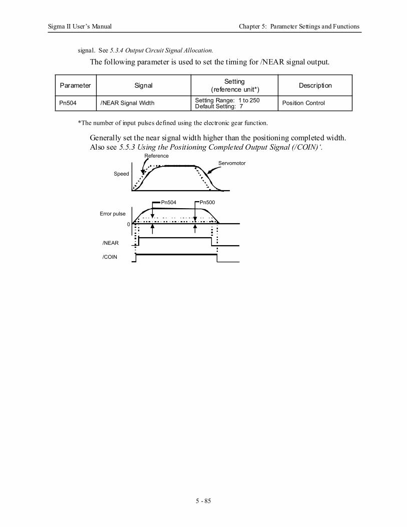
Sigma II User’s Manual Chapter 5: Parameter Settings and Functions
5 - 85
signal. See 5.3.4 Output Circuit Signal Allocation.
The following parameter is used to set the timing for /NEAR signal output.
*The number of input pulses defined using the electronic gear function.
Generally set the near signal width higher than the positioning completed width.Also see 5.5.3 Using the Positioning Completed Output Signal (/COIN)‘.
Parameter Signal Setting(reference unit*) Description
Pn504 /NEAR Signal Width Setting Range: 1 to 250Default Setting: 7 Position Control
/NEAR
/COIN
Pn504 Pn500
0
Speed
Reference Servomotor
Error pulse
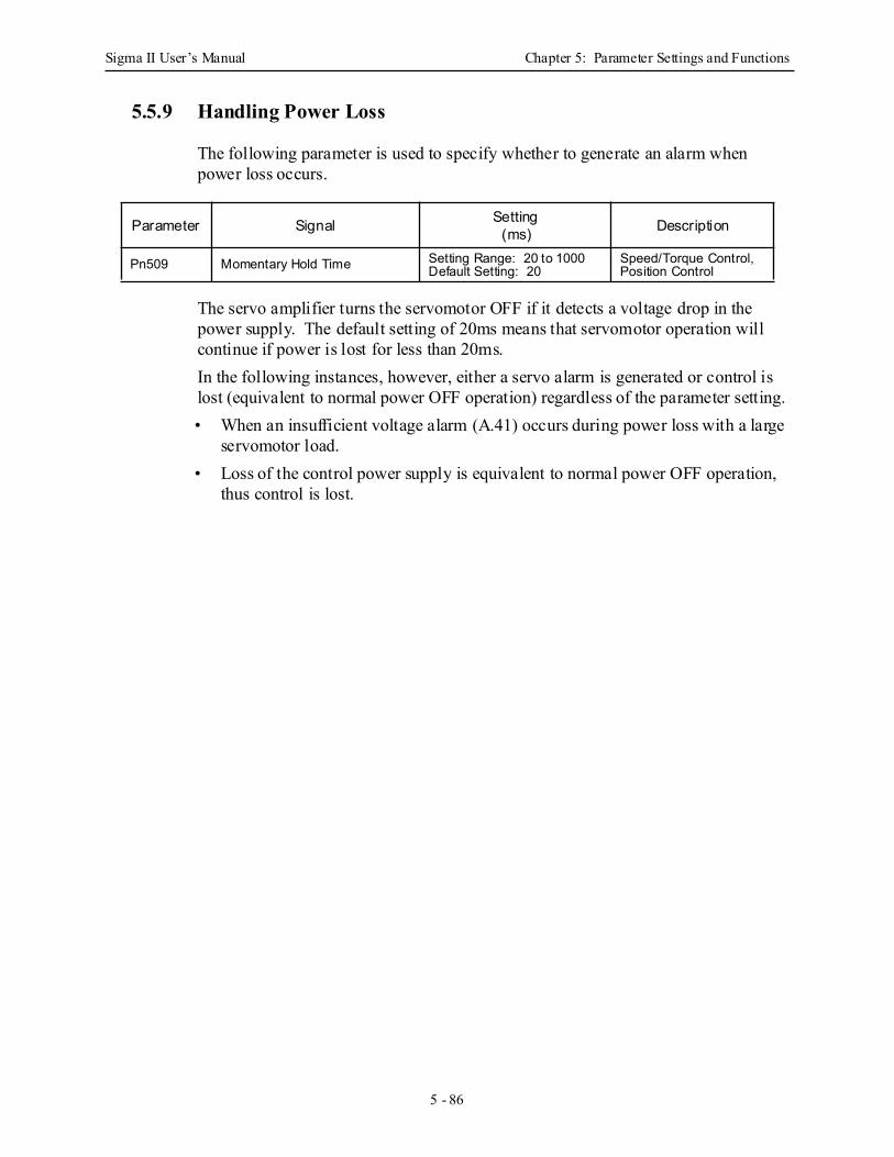
Sigma II User’s Manual Chapter 5: Parameter Settings and Functions
5 - 86
5.5.9 Handling Power Loss
The following parameter is used to specify whether to generate an alarm when power loss occurs.
The servo amplifier turns the servomotor OFF if it detects a voltage drop in the power supply. The default setting of 20ms means that servomotor operation will continue if power is lost for less than 20ms. In the following instances, however, either a servo alarm is generated or control is lost (equivalent to normal power OFF operation) regardless of the parameter setting. • When an insufficient voltage alarm (A.41) occurs during power loss with a large
servomotor load. • Loss of the control power supply is equivalent to normal power OFF operation,
thus control is lost.
Parameter Signal Setting(ms) Description
Pn509 Momentary Hold Time Setting Range: 20 to 1000Default Setting: 20
Speed/Torque Control, Position Control
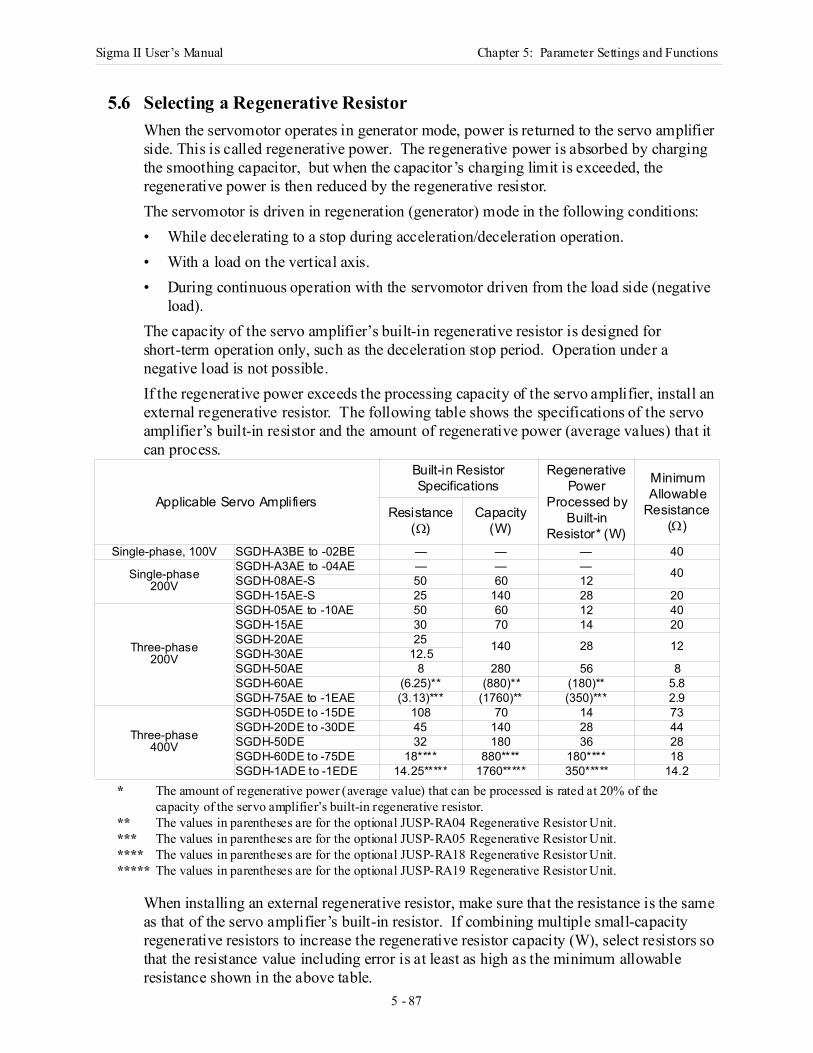
Sigma II User’s Manual Chapter 5: Parameter Settings and Functions
5 - 87
5 Pa rame te r Settings and Functions
5.6 Selecting a Regenerative ResistorWhen the servomotor operates in generator mode, power is returned to the servo amplifier side. This is called regenerative power. The regenerative power is absorbed by charging the smoothing capacitor, but when the capacitor’s charging limit is exceeded, the regenerative power is then reduced by the regenerative resistor. The servomotor is driven in regeneration (generator) mode in the following conditions:• While decelerating to a stop during acceleration/deceleration operation.• With a load on the vertical axis.• During continuous operation with the servomotor driven from the load side (negative
load).The capacity of the servo amplifier’s built-in regenerative resistor is designed for short-term operation only, such as the deceleration stop period. Operation under a negative load is not possible.If the regenerative power exceeds the processing capacity of the servo amplifier, install an external regenerative resistor. The following table shows the specifications of the servo amplifier’s built-in resistor and the amount of regenerative power (average values) that it can process.
* The amount of regenerative power (average value) that can be processed is rated at 20% of the capacity of the servo amplifier’s built-in regenerative resistor.
** The values in parentheses are for the optional JUSP-RA04 Regenerative Resistor Unit.*** The values in parentheses are for the optional JUSP-RA05 Regenerative Resistor Unit.**** The values in parentheses are for the optional JUSP-RA18 Regenerative Resistor Unit.***** The values in parentheses are for the optional JUSP-RA19 Regenerative Resistor Unit.
When installing an external regenerative resistor, make sure that the resistance is the same as that of the servo amplifier’s built-in resistor. If combining multiple small-capacity regenerative resistors to increase the regenerative resistor capacity (W), select resistors so that the resistance value including error is at least as high as the minimum allowable resistance shown in the above table.
Applicable Servo Amplifiers
Built-in ResistorSpecifications
Regenerative Power
Processed by Built-in
Resistor* (W)
Minimum Allowable
Resistance (Ω)
Resistance (Ω)
Capacity (W)
Single-phase, 100V SGDH-A3BE to -02BE — — — 40
Single-phase200V
SGDH-A3AE to -04AE — — — 40SGDH-08AE-S 50 60 12SGDH-15AE-S 25 140 28 20
Three-phase200V
SGDH-05AE to -10AE 50 60 12 40SGDH-15AE 30 70 14 20SGDH-20AE 25 140 28 12SGDH-30AE 12.5SGDH-50AE 8 280 56 8SGDH-60AE (6.25)** (880)** (180)** 5.8SGDH-75AE to -1EAE (3.13)*** (1760)** (350)*** 2.9
Three-phase400V
SGDH-05DE to -15DE 108 70 14 73SGDH-20DE to -30DE 45 140 28 44SGDH-50DE 32 180 36 28SGDH-60DE to -75DE 18**** 880**** 180**** 18SGDH-1ADE to -1EDE 14.25***** 1760***** 350***** 14.2
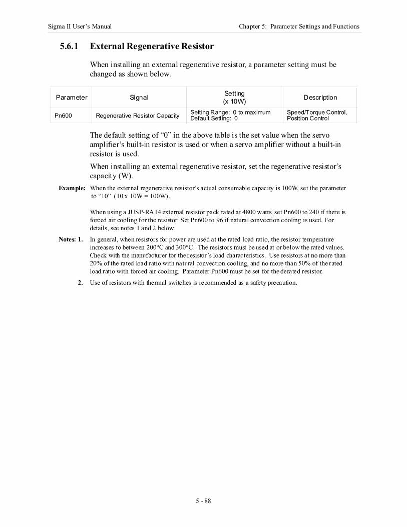
Sigma II User’s Manual Chapter 5: Parameter Settings and Functions
5 - 88
5.6.1 External Regenerative Resistor
When installing an external regenerative resistor, a parameter setting must be changed as shown below.
The default setting of “0” in the above table is the set value when the servo amplifier’s built-in resistor is used or when a servo amplifier without a built-in resistor is used.When installing an external regenerative resistor, set the regenerative resistor’s capacity (W).
Example: When the external regenerative resistor’s actual consumable capacity is 100W, set the parameter to “10” (10 x 10W = 100W).
When using a JUSP-RA14 external resistor pack rated at 4800 watts, set Pn600 to 240 if there is forced air cooling for the resistor. Set Pn600 to 96 if natural convection cooling is used. For details, see notes 1 and 2 below.
Notes: 1. In general, when resistors for power are used at the rated load ratio, the resistor temperature increases to between 200°C and 300°C. The resistors must be used at or below the rated values. Check with the manufacturer for the resistor’s load characteristics. Use resistors at no more than 20% of the rated load ratio with natural convection cooling, and no more than 50% of the rated load ratio with forced air cooling. Parameter Pn600 must be set for the derated resistor.
2. Use of resistors with thermal switches is recommended as a safety precaution.
Parameter Signal Setting(x 10W) Description
Pn600 Regenerative Resistor Capacity Setting Range: 0 to maximumDefault Setting: 0
Speed/Torque Control, Position Control
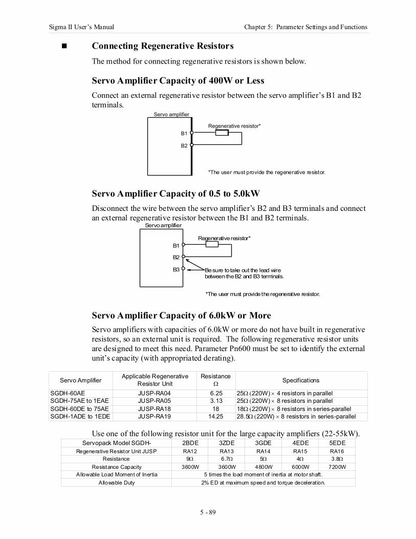
Sigma II User’s Manual Chapter 5: Parameter Settings and Functions
5 - 89
Connecting Regenerative Resistors The method for connecting regenerative resistors is shown below.
Servo Amplifier Capacity of 400W or LessConnect an external regenerative resistor between the servo amplifier’s B1 and B2 terminals.
Servo Amplifier Capacity of 0.5 to 5.0kWDisconnect the wire between the servo amplifier’s B2 and B3 terminals and connect an external regenerative resistor between the B1 and B2 terminals.
Servo Amplifier Capacity of 6.0kW or MoreServo amplifiers with capacities of 6.0kW or more do not have built in regenerative resistors, so an external unit is required. The following regenerative resistor units are designed to meet this need. Parameter Pn600 must be set to identify the external unit’s capacity (with appropriated derating).
Use one of the following resistor unit for the large capacity amplifiers (22-55kW).
Servo Amplifier Applicable Regenerative Resistor Unit
ResistanceΩ Specifications
SGDH-60AE JUSP-RA04 6.25 25Ω (220W) × 4 resistors in parallelSGDH-75AE to 1EAE JUSP-RA05 3.13 25Ω (220W) × 8 resistors in parallelSGDH-60DE to 75AE JUSP-RA18 18 18Ω (220W) × 8 resistors in series-parallelSGDH-1ADE to 1EDE JUSP-RA19 14.25 28.5Ω (220W) × 8 resistors in series-parallel
Servopack Model SGDH- 2BDE 3ZDE 3GDE 4EDE 5EDERegenerative Resistor Unit JUSP RA12 RA13 RA14 RA15 RA16
Resistance 9Ω 6.7Ω 5Ω 4Ω 3.8ΩResistance Capacity 3600W 3600W 4800W 6000W 7200W
Allowable Load Moment of Inertia 5 times the load moment of inertia at motor shaft .Allowable Duty 2% ED at maximum speed and torque decelerat ion.
Servo amplifier
B1
B2
Regenerative resistor*
*The user must provide the regenerative resistor.
Servo amplifier
Regenerative resistor*
Be sure to take out the lead wirebetween the B2 and B3 terminals.
*The user must provide the regenerative resistor.
B3
B2
B1
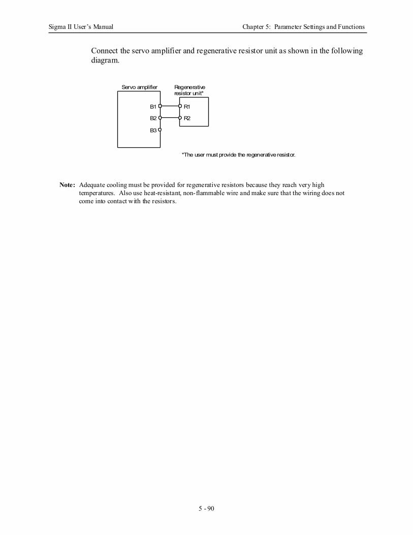
Sigma II User’s Manual Chapter 5: Parameter Settings and Functions
5 - 90
Connect the servo amplifier and regenerative resistor unit as shown in the following diagram.
Note: Adequate cooling must be provided for regenerative resistors because they reach very high temperatures. Also use heat-resistant, non-flammable wire and make sure that the wiring does not come into contact with the resistors.
Servo amplifier Regenerative
*The user must provide the regenerative resistor.
B3
B2
B1
resistor unit*
R2
R1
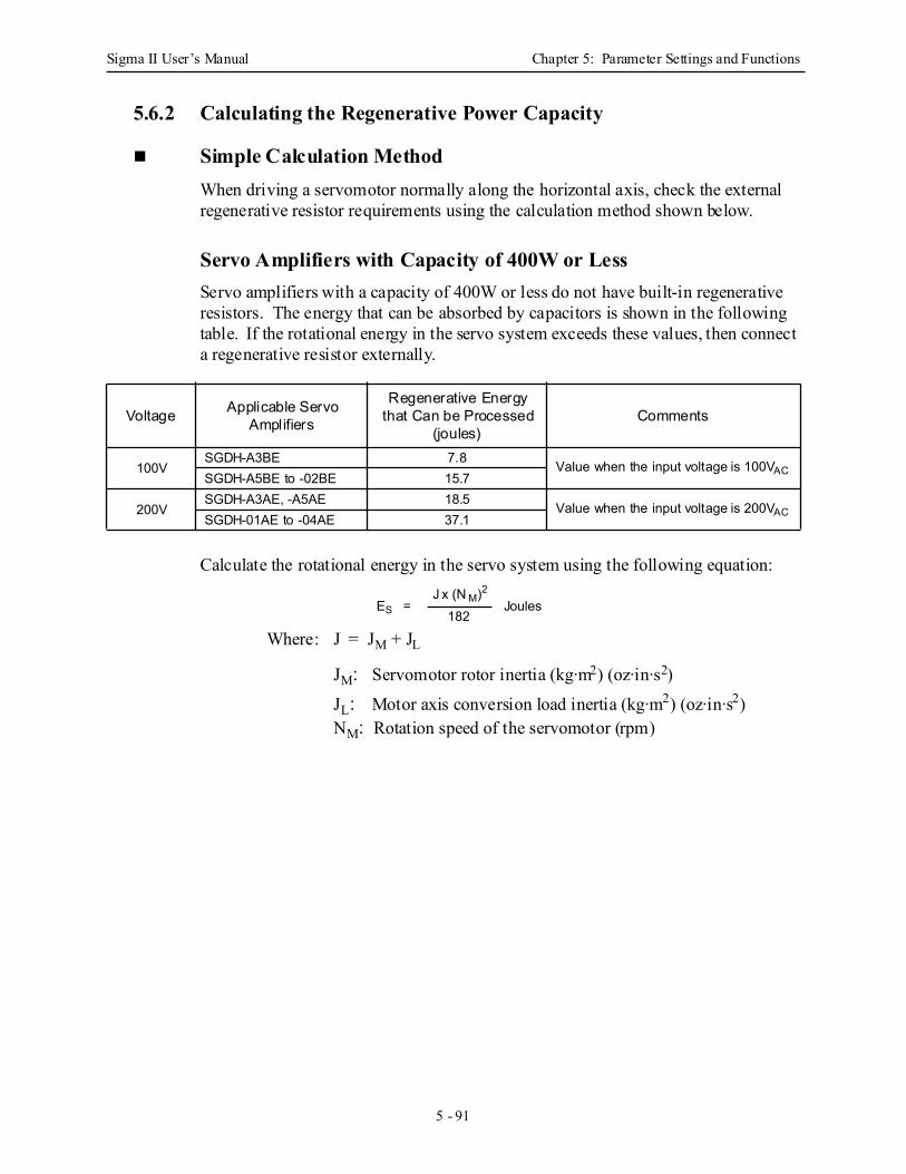
Sigma II User’s Manual Chapter 5: Parameter Settings and Functions
5 - 91
5.6.2 Calculating the Regenerative Power Capacity
Simple Calculation MethodWhen driving a servomotor normally along the horizontal axis, check the external regenerative resistor requirements using the calculation method shown below.
Servo Amplifiers with Capacity of 400W or Less Servo amplifiers with a capacity of 400W or less do not have built-in regenerative resistors. The energy that can be absorbed by capacitors is shown in the following table. If the rotational energy in the servo system exceeds these values, then connect a regenerative resistor externally.
Calculate the rotational energy in the servo system using the following equation:
Where: J = JM + JL
JM: Servomotor rotor inertia (kg·m2) (oz·in·s2)
JL: Motor axis conversion load inertia (kg·m2) (oz·in·s2)NM: Rotation speed of the servomotor (rpm)
Voltage Applicable Servo Amplifiers
Regenerative Energy that Can be Processed
(joules)Comments
100VSGDH-A3BE 7.8 Value when the input voltage is 100VACSGDH-A5BE to -02BE 15.7
200VSGDH-A3AE, -A5AE 18.5 Value when the input voltage is 200VACSGDH-01AE to -04AE 37.1
ES = J x (N M)2
182 Joules
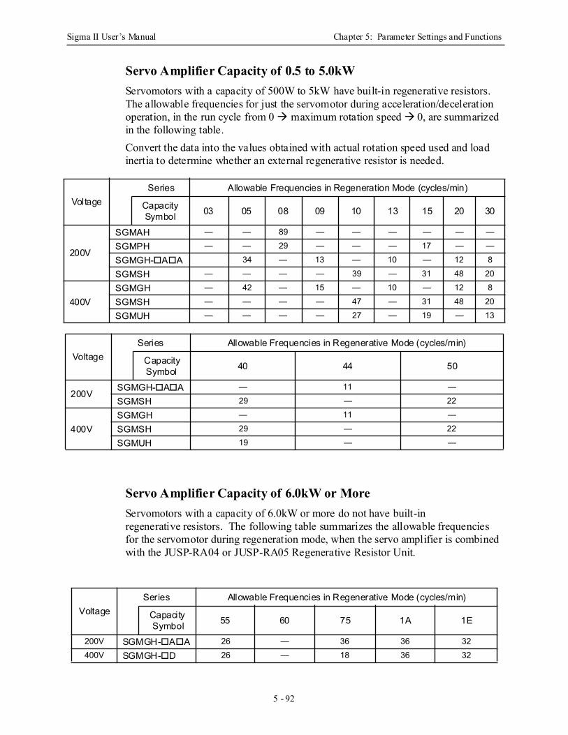
Sigma II User’s Manual Chapter 5: Parameter Settings and Functions
5 - 92
Servo Amplifier Capacity of 0.5 to 5.0kW Servomotors with a capacity of 500W to 5kW have built-in regenerative resistors. The allowable frequencies for just the servomotor during acceleration/deceleration operation, in the run cycle from 0 maximum rotation speed 0, are summarized in the following table.Convert the data into the values obtained with actual rotation speed used and load inertia to determine whether an external regenerative resistor is needed.
Servo Amplifier Capacity of 6.0kW or More Servomotors with a capacity of 6.0kW or more do not have built-in regenerative resistors. The following table summarizes the allowable frequencies for the servomotor during regeneration mode, when the servo amplifier is combined with the JUSP-RA04 or JUSP-RA05 Regenerative Resistor Unit.
VoltageSeries Allowable Frequencies in Regeneration Mode (cycles/min)
Capacity Symbol 03 05 08 09 10 13 15 20 30
200V
SGMAH — — 89 — — — — — —
SGMPH — — 29 — — — 17 — —
SGMGH- A A 34 — 13 — 10 — 12 8
SGMSH — — — — 39 — 31 48 20
400VSGMGH — 42 — 15 — 10 — 12 8
SGMSH — — — — 47 — 31 48 20
SGMUH — — — — 27 — 19 — 13
VoltageSeries Allowable Frequencies in Regenerative Mode (cycles/min)
Capacity Symbol 40 44 50
200VSGMGH- A A — 11 —
SGMSH 29 — 22
400VSGMGH — 11 —
SGMSH 29 — 22
SGMUH 19 — —
VoltageSeries Allowable Frequencies in Regenerative Mode (cycles/min)
Capacity Symbol 55 60 75 1A 1E
200V SGMGH- A A 26 — 36 36 32400V SGMGH- D 26 — 18 36 32
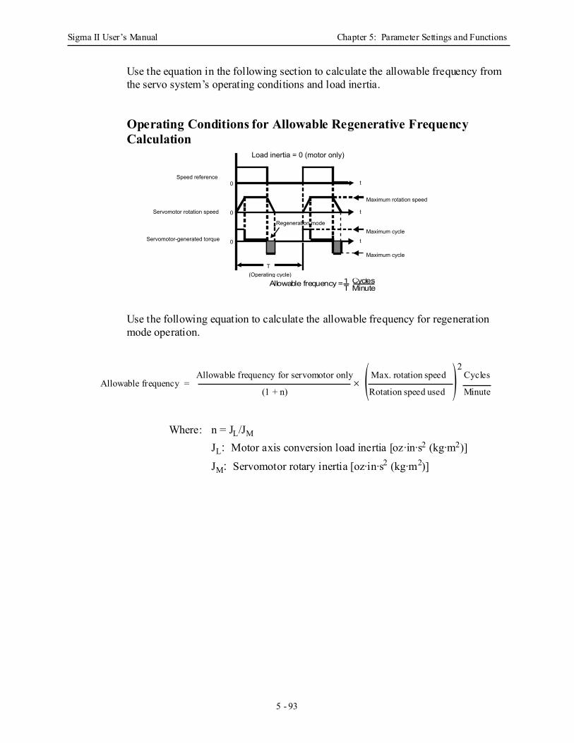
Sigma II User’s Manual Chapter 5: Parameter Settings and Functions
5 - 93
Use the equation in the following section to calculate the allowable frequency from the servo system’s operating conditions and load inertia.
Operating Conditions for Allowable Regenerative FrequencyCalculation
Use the following equation to calculate the allowable frequency for regeneration mode operation.
Where: n = JL/JM
JL: Motor axis conversion load inertia [oz·in·s2 (kg·m2)]
JM: Servomotor rotary inertia [oz·in·s2 (kg·m2)]
Allowable frequency = 1 CyclesT Minute
Speed reference
Servomotor rotation speed
Servomotor-generated torque
Load inertia = 0 (motor only)
Regeneration mode
T(Operating cycle)
Maximum rotation speed
Maximum cycle
0
Maximum cycle
0
0
t
t
t
Allowable frequency = Allowable frequency for servomotor only
(1 + n)× ( )Max. rotation speed
Rotation speed used
2Cycles
Minute
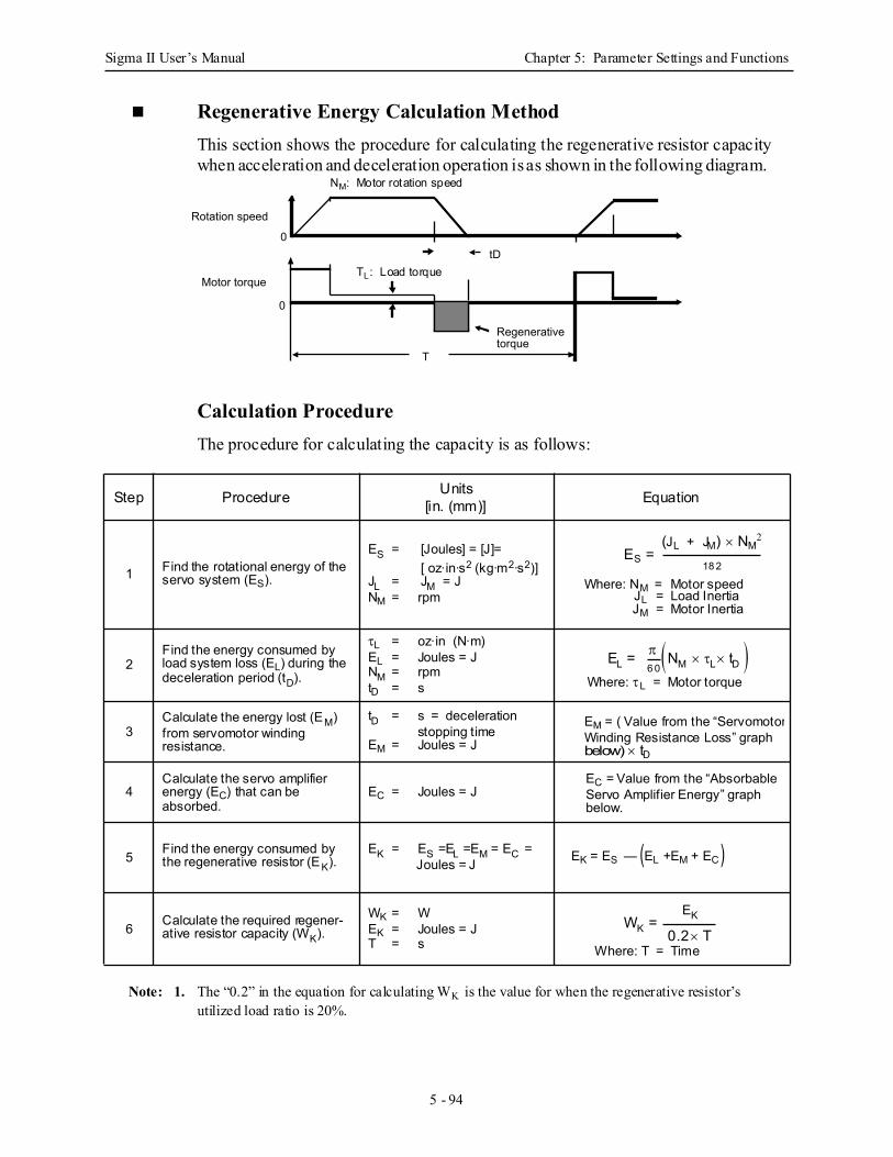
Sigma II User’s Manual Chapter 5: Parameter Settings and Functions
5 - 94
Regenerative Energy Calculation Method This section shows the procedure for calculating the regenerative resistor capacity when acceleration and deceleration operation is as shown in the following diagram.
Calculation Procedure The procedure for calculating the capacity is as follows:
Note: 1. The “0.2” in the equation for calculating WK is the value for when the regenerative resistor’s utilized load ratio is 20%.
Step Procedure Units[in. (mm)] Equation
1 Find the rotational energy of the servo system (ES).
ES = [Joules] = [J]=[ oz·in·s2 (kg·m2·s2)]
JL = JM = J NM = rpm
2Find the energy consumed by load system loss (EL) during the deceleration period (tD).
τL = oz·in (N·m)EL = Joules = JNM = rpmtD = s
3Calculate the energy lost (EM) from servomotor windingresistance.
tD = s = deceleration stopping time
EM = Joules = J
4Calculate the servo amplifier energy (EC) that can be absorbed.
EC = Joules = J
5 Find the energy consumed by the regenerative resistor (EK).
EK = ES =EL =EM = EC = Joules = J
6 Calculate the required regener-ative resistor capacity (WK).
WK = WEK = Joules = JT = s
Rotation speed
Motor torque
tD0
0
Regenerative torque
T
NM: Motor rotation speed
TL: Load torque
ES = (JL + JM) × NM
2
18 2
Where: NM = Motor speed JL = Load Inertia
JM = Motor Inertia
EL = π6 0
NM × τL× tD( )Where: τL = Motor torque
EM = ( Value from the “ServomotorWinding Resistance Loss” graphbelow) × tDEC = Value from the “AbsorbableServo Amplifier Energy” graphbelow.
EK = ES — EL +EM + EC ( )
WK = EK
0.2 × TWhere: T = Time
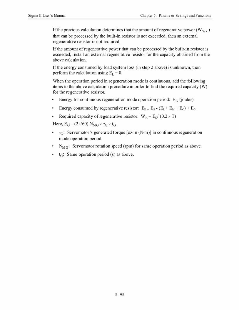
Sigma II User’s Manual Chapter 5: Parameter Settings and Functions
5 - 95
If the previous calculation determines that the amount of regenerative power (WWk.) that can be processed by the built-in resistor is not exceeded, then an external regenerative resistor is not required.If the amount of regenerative power that can be processed by the built-in resistor is exceeded, install an external regenerative resistor for the capacity obtained from the above calculation.If the energy consumed by load system loss (in step 2 above) is unknown, then perform the calculation using EL = 0.
When the operation period in regeneration mode is continuous, add the following items to the above calculation procedure in order to find the required capacity (W) for the regenerative resistor.• Energy for continuous regeneration mode operation period: EG (joules)
• Energy consumed by regenerative resistor: EK = ES - (EL + EM + EC) + EG
• Required capacity of regenerative resistor: WK = EK/ (0.2 × T)Here, EG = (2π/60) NMG × τG × tG
• τG: Servomotor’s generated torque [oz·in (N·m)] in continuous regeneration mode operation period.
• NMG: Servomotor rotation speed (rpm) for same operation period as above.
• tG: Same operation period (s) as above.
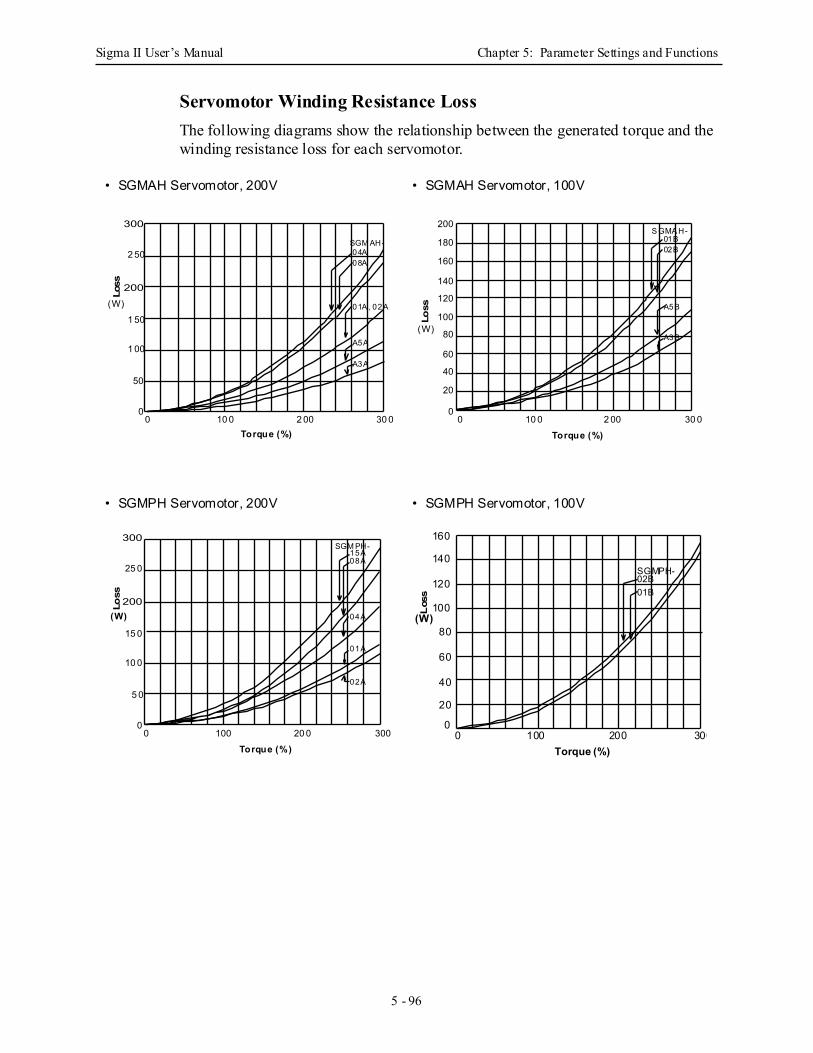
Sigma II User’s Manual Chapter 5: Parameter Settings and Functions
5 - 96
Servomotor Winding Resistance Loss The following diagrams show the relationship between the generated torque and the winding resistance loss for each servomotor.
• SGMAH Servomotor, 200V • SGMAH Servomotor, 100V
• SGMPH Servomotor, 200V • SGMPH Servomotor, 100V
200
2 50
1 50
1 00
50
00 10 0 2 00 30 0
300
Torque (%)
(W)
SGM AH-04A08A
01A , 02A
A5A
A3A
Loss
200
180
160
140
120
100
80
60
40
20
00 10 0 2 00 30 0
Torque (%)
S GMA H-01B02B
A5B
A3B(W)
Loss
200
25 0
15 0
10 0
5 0
00 100 20 0 300
300
Torque (%)
(W)
SGM PH-15A08A
04A
01A
02A
Loss
160
140
120
100
80
60
40
20
00 100 200 300
Torque (%)
(W)
SGMPH-02B01B
Los
s
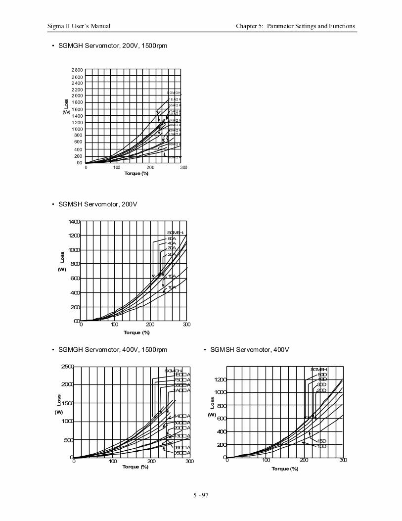
Sigma II User’s Manual Chapter 5: Parameter Settings and Functions
5 - 97
• SGMGH Servomotor, 200V, 1500rpm
• SGMSH Servomotor, 200V
• SGMGH Servomotor, 400V, 1500rpm • SGMSH Servomotor, 400V
S GM GH-
55A A
75A A
44A A30A A20A A13A A
09A A
05A A
2 800
1 8001 6001 4001 2001 000
800600
400200
00
Torque (%)
Loss
(W)
0 100 200 300
2 6002 4002 2002 000
1E A A
1A A A
SGMSH-50A40A30A20A
15A
10A
1400
1200
1000
800
600
400
200
00
Torque (%)
Loss
(W)
0 100 200 300
SGMGH-
30D A20D A
13D A
09D A05D A
2500
2000
1500
1000
500
0
Torque (%)
Lo
ss
(W)
0 100 200 300
1ED A75D A55D A1AD A
44D A
SGMSH-50D40D30D20D
1200
1000
800
600
400
200
0
Torque (%)
Lo
ss
(W)
0 100 200 300
15D10D
400
200
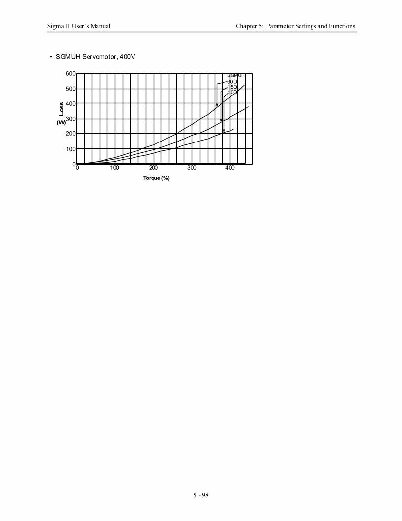
Sigma II User’s Manual Chapter 5: Parameter Settings and Functions
5 - 98
• SGMUH Servomotor, 400V
SGMUH-30D15D10D
600
500
400
300
200
100
0
Torque (%)
Los
s
(W)
0 100 200 300 400
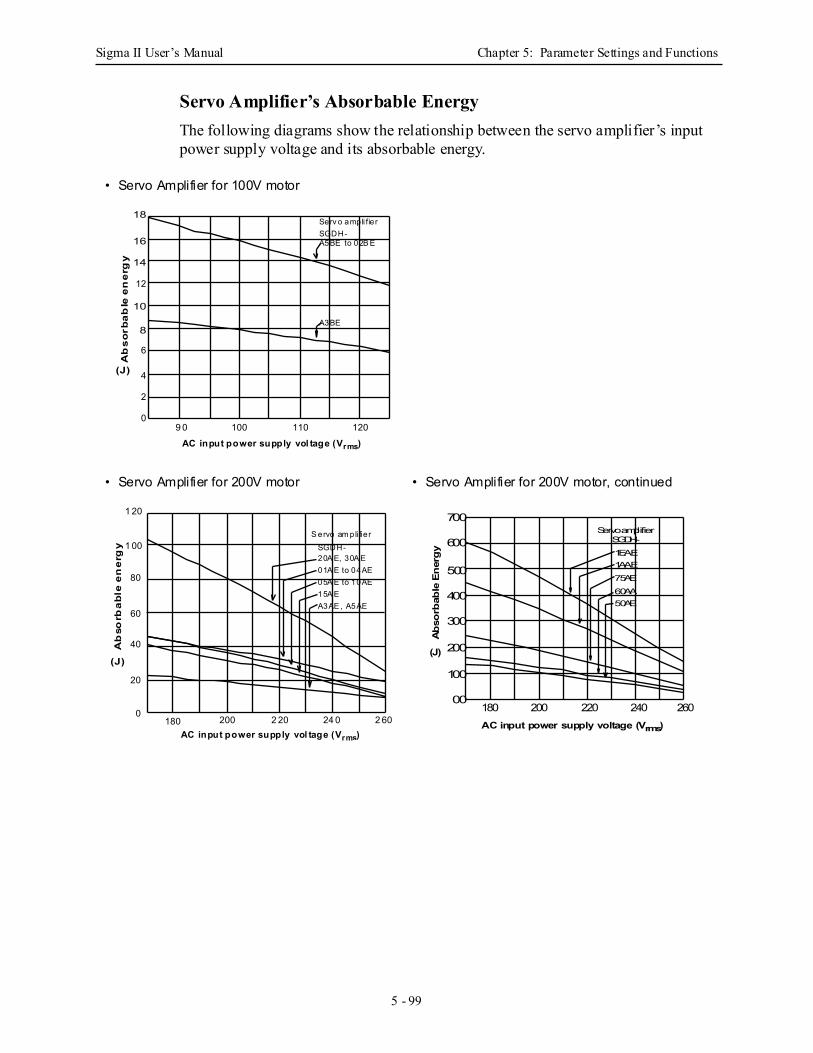
Sigma II User’s Manual Chapter 5: Parameter Settings and Functions
5 - 99
Servo Amplifier’s Absorbable Energy The following diagrams show the relationship between the servo amplifier’s input power supply voltage and its absorbable energy.
• Servo Amplifier for 100V motor
• Servo Amplifier for 200V motor • Servo Amplifier for 200V motor, continued
10
12
6
4
2
09 0 100 110 120
16
8
14
18
AC input power supply vol tage (Vrms)
Serv o ampli fierSGDH-A5BE to 02B E
A3BE
Ab
so
rba
ble
en
erg
y
(J)
Ab
sorb
ab
le e
ne
rgy
(J)
AC input power supply vol tage (Vrms)
1 20
1 00
80
60
40
20
0180 200 24 02 20 2 60
S ervo am pli fierSGDH-20A E, 30A E01A E to 04AE05A E to 10AE15A EA3AE , A5AE
SGDH-Servo amplifier
60AA50AE
700
600
500
400
300
200
100
00
AC input power supply voltage (Vrms)
Ab
sorb
able
En
erg
y
(J)
180 200 220 260240
1EAE1AAE75AE
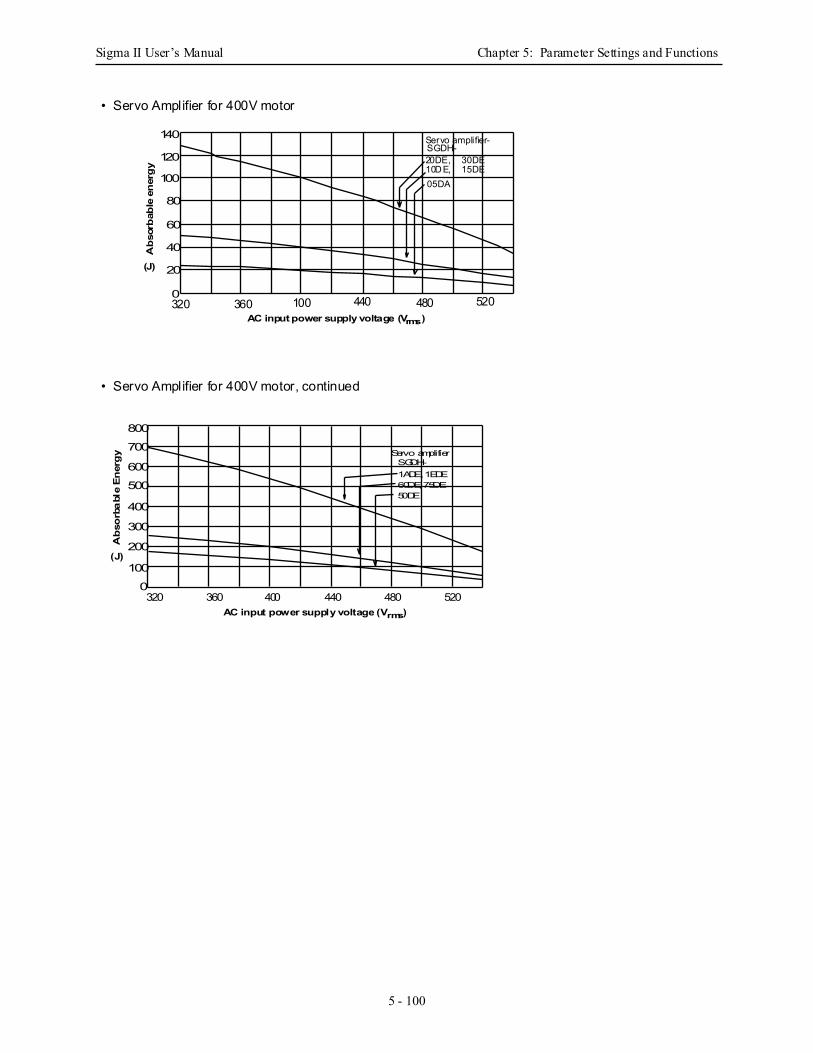
Sigma II User’s Manual Chapter 5: Parameter Settings and Functions
5 - 100
• Servo Amplifier for 400V motor
• Servo Amplifier for 400V motor, continued
SGDH- Servo amplifier-
20DE, 30DE10DE, 15DE05DA
140
120
100
80
60
40
20
0
AC input power supply voltage (Vrms)
Ab
sorb
able
en
erg
y
(J)
320 100 440 480360 520
SGDH- Servo amplifier
50DE
1ADE, 1EDE60DE, 75DE
700
600
500
400
300
200
100
0
AC input power supply voltage (Vrms)
Ab
sorb
abl
e E
ner
gy
(J)
320 360 400 480440 520
800
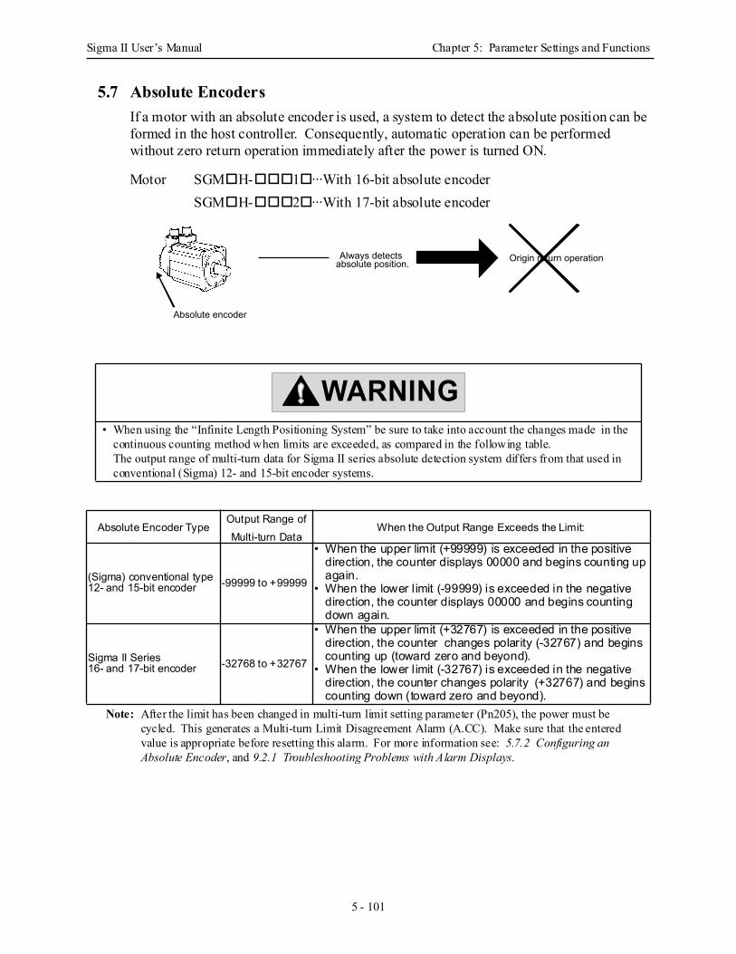
Sigma II User’s Manual Chapter 5: Parameter Settings and Functions
5 - 101
5.7 Absolute EncodersIf a motor with an absolute encoder is used, a system to detect the absolute position can be formed in the host controller. Consequently, automatic operation can be performed without zero return operation immediately after the power is turned ON.
Motor SGM H- 1 ···With 16-bit absolute encoderSGM H- 2 ···With 17-bit absolute encoder
Note: After the limit has been changed in multi-turn limit setting parameter (Pn205), the power must be cycled. This generates a Multi-turn Limit Disagreement Alarm (A.CC). Make sure that the entered value is appropriate before resetting this alarm. For more information see: 5.7.2 Configuring an Absolute Encoder, and 9.2.1 Troubleshooting Problems with Alarm Displays.
• When using the “Infinite Length Positioning System” be sure to take into account the changes made in the continuous counting method when limits are exceeded, as compared in the following table. The output range of multi-turn data for Sigma II series absolute detection system differs from that used in conventional (Sigma) 12- and 15-bit encoder systems.
Absolute Encoder TypeOutput Range of Multi-turn Data
When the Output Range Exceeds the Limit:
(Sigma) conventional type12- and 15-bit encoder -99999 to +99999
• When the upper limit (+99999) is exceeded in the positive direction, the counter displays 00000 and begins counting up again.
• When the lower l imit (-99999) is exceeded in the negative direction, the counter displays 00000 and begins counting down again.
Sigma II Series 16- and 17-bit encoder -32768 to +32767
• When the upper limit (+32767) is exceeded in the positive direction, the counter changes polarity (-32767) and begins counting up (toward zero and beyond).
• When the lower l imit (-32767) is exceeded in the negative direction, the counter changes polarity (+32767) and begins counting down (toward zero and beyond).
Always detects absolute position. Origin return operation
Absolute encoder
WARNING
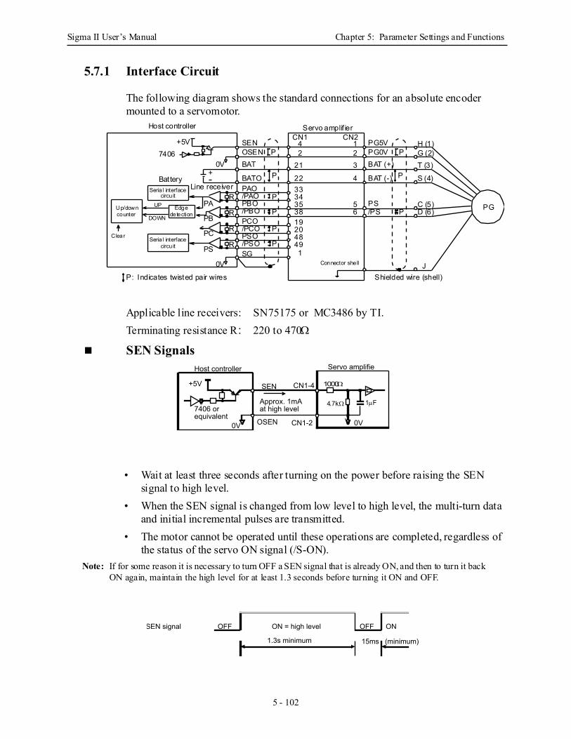
Sigma II User’s Manual Chapter 5: Parameter Settings and Functions
5 - 102
5.7.1 Interface Circuit
The following diagram shows the standard connections for an absolute encoder mounted to a servomotor.
Applicable line receivers: SN75175 or MC3486 by TI.Terminating resistance R: 220 to 470Ω
SEN Signals
• Wait at least three seconds after turning on the power before raising the SEN signal to high level.
• When the SEN signal is changed from low level to high level, the multi-turn data and initial incremental pulses are transmitted.
• The motor cannot be operated until these operations are completed, regardless of the status of the servo ON signal (/S-ON).
Note: If for some reason it is necessary to turn OFF a SEN signal that is already ON, and then to turn it back ON again, maintain the high level for at least 1.3 seconds before turning it ON and OFF.
SENOSENBAT
BATOPAO/PAOPBO/PBOPCO/PCOPSO/PSOSG
BAT (+)
BAT (-)
PG5VPG0V
PS/PS
Servo amplif ierHost controller
+5V7406
Battery
0V
CN1 CN242
21
2233343538192048491
123
4
56
P
P
P
P
P P
P
P P
Seria l interfacecircu it
Edge
Line receiverR
R
R
R
PA
PB
PC
PS
detectionUp/downcounter
UP
DOWN
Clear
H (1)G (2)T (3)
S (4)
C (5)D (6)
JShielded wire (shell)P: Indicates twisted pair wires
Connector shell
+
0V
Seria l interfacecircu it
PG
SEN
OSEN
Host controller Servo amplifie
CN1-2
CN1-4+5V
Approx. 1mA at high level
0V
7406 or equivalent
0V
1000Ω
4.7kΩ 1µF
OFF ON = high level
1.3s minimum
OFF ON
15ms (minimum)
SEN signal
Sigma II User’s Manual Chapter 5: Parameter Settings and Functions
5 - 103
5.7.2 Configuring an Absolute Encoder
Select the absolute encoder’s application with the following parameter.
Either “0” or “1” in the following table must be set in order to enable the absolute encoder.
The following parameter is used to periodically clear the encoder’s counter (return the setting to 0) after a designated ratio of motor to load axis revolutions. This function is called the multi-turn limit.
Note: The term Multi-turn Limit refers to the highest number of rotations the encoder’s counter will dis-play before returning the counter to 0.
• When Pn205 is set to the default (65535), multi-turn data varies in the range of −32768 to +32767.
• With any other Pn205 value entered, data varies from 0 to the set value.
Note: To activate reassignment of this value, the user must first enter the change to the parameter, and then cycle (turn OFF and then turn ON) the power.
Since the encoder’s multi-turn limit value is set as default to 65535, the following alarm occurs if the servo amplifier’s power supply is cycled (turned OFF and ON) after changing parameter Pn205:
Note: O: ON (“L”) signalX: OFF (“H”) signal
In order to set a multi-turn limit value to the encoder, perform the multi-term limit setting operation (Fn-013).
This operation can be executed using the hand-held digital operator or the servo
Parameter Signal Setting Description
Pn002.2 Absolute Encoder Application Setting Range: 0 or 1Default Setting: 0
Speed/Torque Control, Position Control
Pn002.2 Setting Result0 Uses the absolute encoder as an absolute encoder. 1 Uses the absolute encoder as an incremental encoder.
Parameter Signal Setting Description
Pn205 Multi-turn Limit Setting Setting Range: 0 to 65535Default Setting: 65535
Speed/Torque Control, Position Control
Alarm DisplayAlarm Code Output
DescriptionALO1 ALO2 ALO3
A.CC O X O Encoder multi-turn limit value does not match with that of the servo amplifier.
Sigma II User’s Manual Chapter 5: Parameter Settings and Functions
5 - 104
amplifier panel operator. Note: The multi-turn limit setting is enabled only during the multi-turn limit value mismatch alarm. Cycle
the power after performing this operation.
• Connect the ground terminal to a class-3 ground (100Ω or less).Improper grounding may result in electric shock or fire.
WARNING

Sigma II User’s Manual Chapter 5: Parameter Settings and Functions
5 - 105
5.7.3 Handling Batteries
In order for the absolute encoder to retain position data when the power is turned OFF, the data must be backed up by a battery.
Installing the Battery at the Host DeviceLithium battery, by Toshiba: ER6VC3, 3.6V, 2000mAh
Battery Provided for Servo Amplifier Lithium battery: JZSP-BA01 (includes battery and connector)Battery: Toshiba, ER3 V, 3.6V, 1000mAh
• Install the battery at either the host controller or the servo amplifier, NEVER at both simultaneously.Such a connection would create a circuit between the batteries, which could lead to electric shock, injury, or equipment damage.
Battery carrying space
Batter connector (CN8)
CN8
CN5CN3
Batt ery connector (CN8)Batt ery carrying sp ace
For amplif ier of 30W to 5kW
F or amplifier of 6.0 to 55kW
WARNING
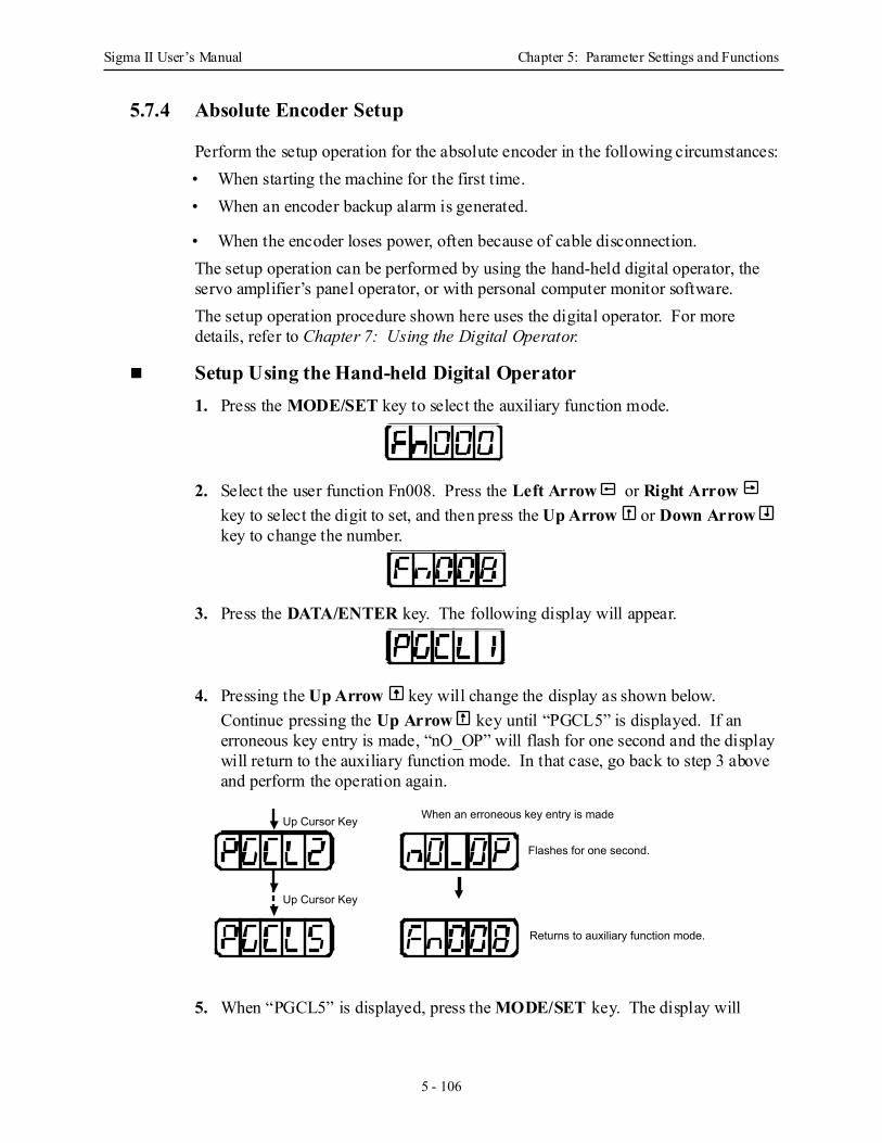
Sigma II User’s Manual Chapter 5: Parameter Settings and Functions
5 - 106
5.7.4 Absolute Encoder Setup
Perform the setup operation for the absolute encoder in the following circumstances:• When starting the machine for the first time.• When an encoder backup alarm is generated.
• When the encoder loses power, often because of cable disconnection.The setup operation can be performed by using the hand-held digital operator, the servo amplifier’s panel operator, or with personal computer monitor software.The setup operation procedure shown here uses the digital operator. For more details, refer to Chapter 7: Using the Digital Operator.
Setup Using the Hand-held Digital Operator 1. Press the MODE/SET key to select the auxiliary function mode.
2. Select the user function Fn008. Press the Left Arrow or Right Arrow key to select the digit to set, and then press the Up Arrow or Down Arrow key to change the number.
3. Press the DATA/ENTER key. The following display will appear.
4. Pressing the Up Arrow key will change the display as shown below. Continue pressing the Up Arrow key until “PGCL5” is displayed. If an erroneous key entry is made, “nO_OP” will flash for one second and the display will return to the auxiliary function mode. In that case, go back to step 3 above and perform the operation again.
5. When “PGCL5” is displayed, press the MODE/SET key. The display will
Up Cursor Key When an erroneous key entry is made
Flashes for one second.
Returns to auxiliary function mode.
Up Cursor Key
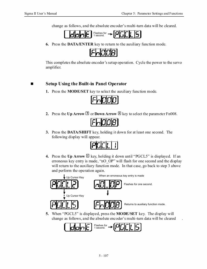
Sigma II User’s Manual Chapter 5: Parameter Settings and Functions
5 - 107
change as follows, and the absolute encoder’s multi-turn data will be cleared.
6. Press the DATA/ENTER key to return to the auxiliary function mode.
This completes the absolute encoder’s setup operation. Cycle the power to the servo amplifier.
Setup Using the Built-in Panel Operator 1. Press the MODE/SET key to select the auxiliary function mode.
2. Press the Up Arrow or Down Arrow key to select the parameter Fn008.
3. Press the DATA/SHIFT key, holding it down for at least one second. The following display will appear.
4. Press the Up Arrow key, holding it down until “PGCL5” is displayed. If an erroneous key entry is made, “nO_OP” will flash for one second and the display will return to the auxiliary function mode. In that case, go back to step 3 above and perform the operation again.
5. When “PGCL5” is displayed, press the MODE/SET key. The display will change as follows, and the absolute encoder’s multi-turn data will be cleared .
Flashes for 1 second.
Up Cursor Key When an erroneous key entry is made
Flashes for one second.
Returns to auxiliary function mode.
Up Cursor Key
Flashes for 1 second.
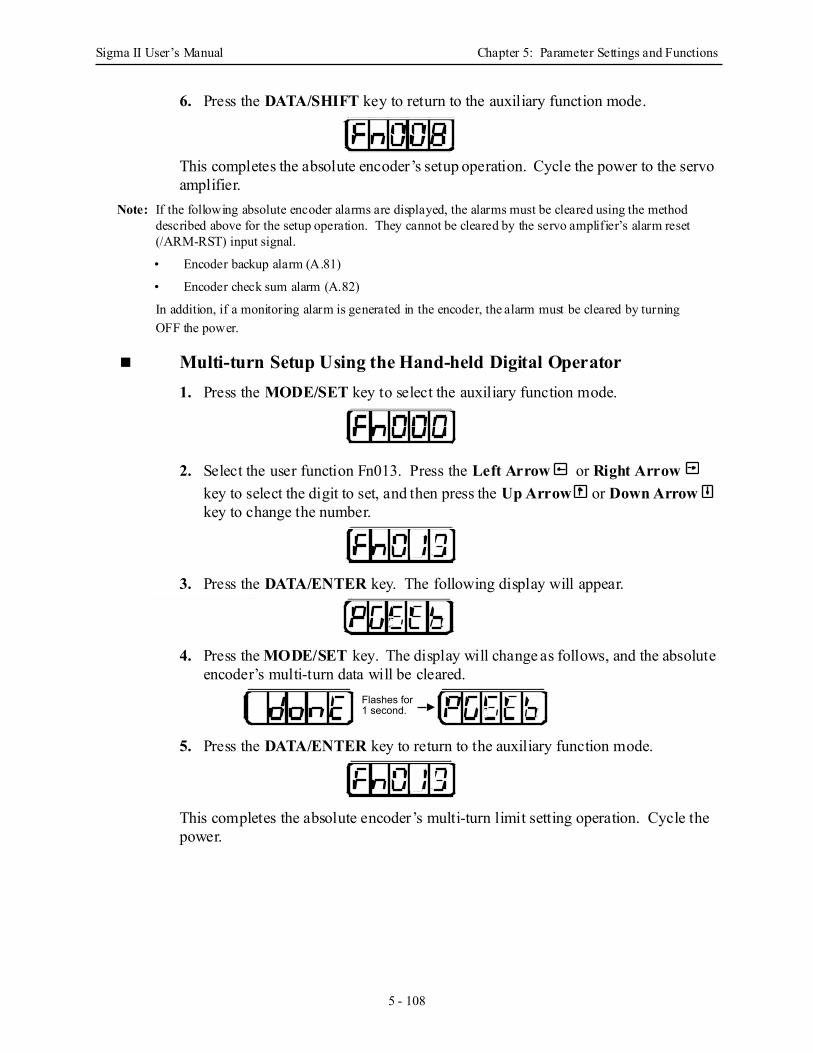
Sigma II User’s Manual Chapter 5: Parameter Settings and Functions
5 - 108
6. Press the DATA/SHIFT key to return to the auxiliary function mode.
This completes the absolute encoder’s setup operation. Cycle the power to the servo amplifier.
Note: If the following absolute encoder alarms are displayed, the alarms must be cleared using the method described above for the setup operation. They cannot be cleared by the servo amplifier’s alarm reset (/ARM-RST) input signal.
• Encoder backup alarm (A.81)
• Encoder check sum alarm (A.82)
In addition, if a monitoring alarm is generated in the encoder, the alarm must be cleared by turning OFF the power.
Multi-turn Setup Using the Hand-held Digital Operator 1. Press the MODE/SET key to select the auxiliary function mode.
2. Select the user function Fn013. Press the Left Arrow or Right Arrow key to select the digit to set, and then press the Up Arrow or Down Arrow key to change the number.
3. Press the DATA/ENTER key. The following display will appear.
4. Press the MODE/SET key. The display will change as follows, and the absolute encoder’s multi-turn data will be cleared.
5. Press the DATA/ENTER key to return to the auxiliary function mode.
This completes the absolute encoder’s multi-turn limit setting operation. Cycle the power.
Flashes for 1 second.
Flashes for 1 second.
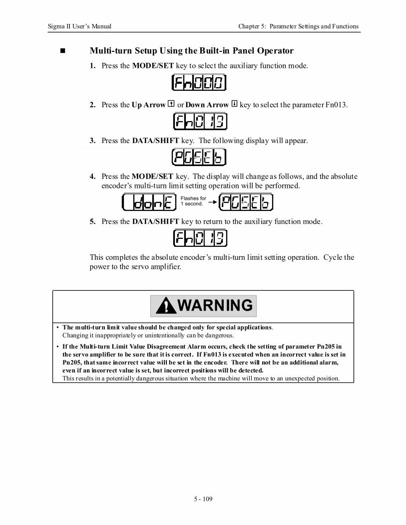
Sigma II User’s Manual Chapter 5: Parameter Settings and Functions
5 - 109
Multi-turn Setup Using the Built-in Panel Operator 1. Press the MODE/SET key to select the auxiliary function mode.
2. Press the Up Arrow or Down Arrow key to select the parameter Fn013.
3. Press the DATA/SHIFT key. The following display will appear.
4. Press the MODE/SET key. The display will change as follows, and the absolute encoder’s multi-turn limit setting operation will be performed.
5. Press the DATA/SHIFT key to return to the auxiliary function mode.
This completes the absolute encoder’s multi-turn limit setting operation. Cycle the power to the servo amplifier.
• The multi-turn limit value should be changed only for special applications. Changing it inappropriately or unintentionally can be dangerous.
• If the Multi-turn Limit Value Disagreement Alarm occurs, check the setting of parameter Pn205 in the servo amplifier to be sure that it is correct. If Fn013 is executed when an incorrect value is set in Pn205, that same incorrect value will be set in the encoder. There will not be an additional alarm, even if an incorrect value is set, but incorrect positions will be detected.This results in a potentially dangerous situation where the machine will move to an unexpected position.
Flashes for 1 second.
Flashes for 1 second.
WARNING
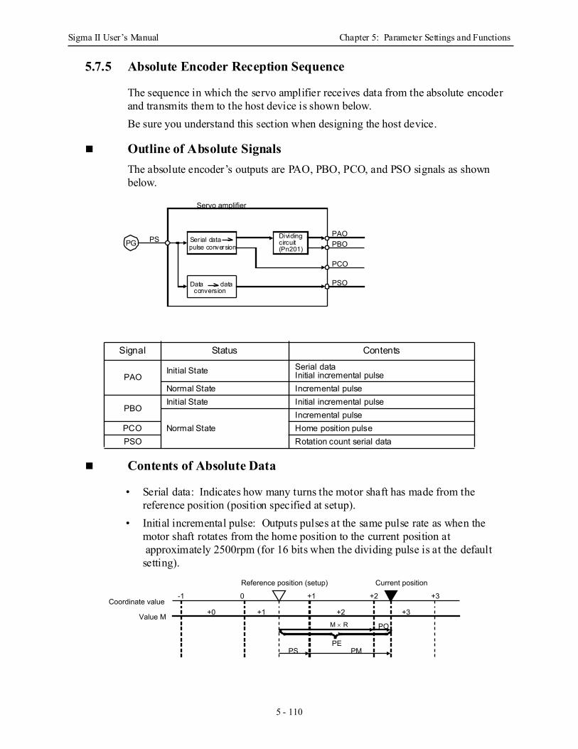
Sigma II User’s Manual Chapter 5: Parameter Settings and Functions
5 - 110
5.7.5 Absolute Encoder Reception Sequence
The sequence in which the servo amplifier receives data from the absolute encoder and transmits them to the host device is shown below. Be sure you understand this section when designing the host device.
Outline of Absolute Signals The absolute encoder’s outputs are PAO, PBO, PCO, and PSO signals as shown below.
Contents of Absolute Data
• Serial data: Indicates how many turns the motor shaft has made from the reference position (position specified at setup).
• Initial incremental pulse: Outputs pulses at the same pulse rate as when the motor shaft rotates from the home position to the current position at approximately 2500rpm (for 16 bits when the dividing pulse is at the default setting).
Signal Status Contents
PAOInitial State Serial data
Initial incremental pulse Normal State Incremental pulse
PBOInitial State Initial incremental pulse
Normal StateIncremental pulse
PCO Home position pulsePSO Rotation count serial data
Servo amplifier
PSPAOPBO
PCO
PSO
PG Serial datapulse conversion
Data dataconversion
Dividingcircuit(Pn201)
Coordinate value
Value M
Reference position (setup)
-1 0 +1 +2 +3
+3
Current position
+2+1+0
PMPE
PS
POM × R
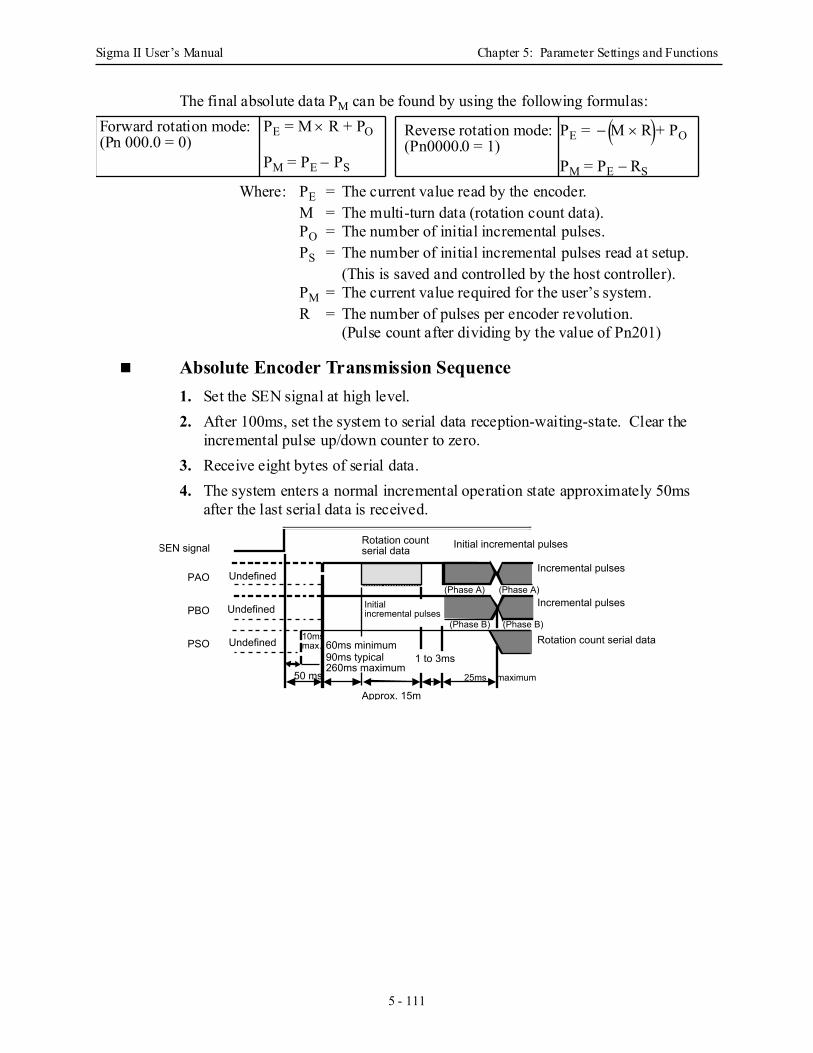
Sigma II User’s Manual Chapter 5: Parameter Settings and Functions
5 - 111
The final absolute data PM can be found by using the following formulas:
Where: PE = The current value read by the encoder.M = The multi-turn data (rotation count data).PO = The number of initial incremental pulses.PS = The number of initial incremental pulses read at setup.
(This is saved and controlled by the host controller).PM = The current value required for the user’s system.R = The number of pulses per encoder revolution.
(Pulse count after dividing by the value of Pn201)
Absolute Encoder Transmission Sequence 1. Set the SEN signal at high level.2. After 100ms, set the system to serial data reception-waiting-state. Clear the
incremental pulse up/down counter to zero.3. Receive eight bytes of serial data.4. The system enters a normal incremental operation state approximately 50ms
after the last serial data is received.
PE = M × R + PO
PM = PE − PS
Forward rotation mode: PE = − M × R + PO
PM = PE − RS
Reverse rotation mode:(Pn0000.0 = 1)
( ) (Pn 000.0 = 0)
SEN signal
PAO
PBO
PSO
Incremental pulses
Incremental pulses
Rotation count serial data
Initial incremental pulses
Undefined
Undefined
Undefined
50 ms
60ms minimum90ms typical260ms maximum
10ms max.
Approx. 15ms
1 to 3ms
25ms maximum
Rotation count serial data
Initialincremental pulses
(Phase A)(Phase A)
(Phase B) (Phase B)
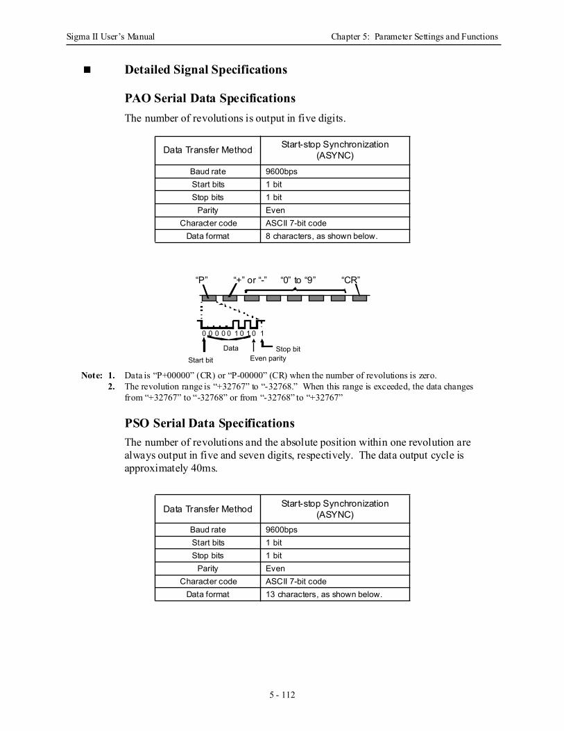
Sigma II User’s Manual Chapter 5: Parameter Settings and Functions
5 - 112
Detailed Signal Specifications
PAO Serial Data Specifications The number of revolutions is output in five digits.
Note: 1. Data is “P+00000” (CR) or “P-00000” (CR) when the number of revolutions is zero.2. The revolution range is “+32767” to “-32768.” When this range is exceeded, the data changes
from “+32767” to “-32768” or from “-32768” to “+32767”
PSO Serial Data Specifications The number of revolutions and the absolute position within one revolution are always output in five and seven digits, respectively. The data output cycle is approximately 40ms.
Data Transfer Method Start-stop Synchronization (ASYNC)
Baud rate 9600bpsStart bits 1 bitStop bits 1 bit
Parity EvenCharacter code ASCII 7-bit code
Data format 8 characters, as shown below.
Data Transfer Method Start-stop Synchronization (ASYNC)
Baud rate 9600bpsStart bits 1 bitStop bits 1 bit
Parity EvenCharacter code ASCII 7-bit code
Data format 13 characters, as shown below.
0 0 0 0 0 1 0 1 0
DataStart bit Even parity
1
Stop bit
“P” “+” or “-” “0” to “9” “CR”
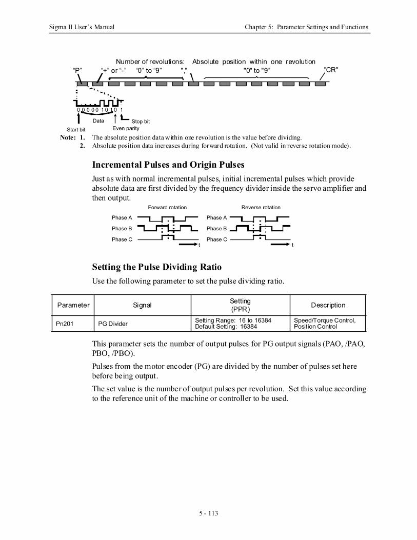
Sigma II User’s Manual Chapter 5: Parameter Settings and Functions
5 - 113
Note: 1. The absolute position data within one revolution is the value before dividing.2. Absolute position data increases during forward rotation. (Not valid in reverse rotation mode).
Incremental Pulses and Origin Pulses Just as with normal incremental pulses, initial incremental pulses which provide absolute data are first divided by the frequency divider inside the servo amplifier and then output.
Setting the Pulse Dividing Ratio Use the following parameter to set the pulse dividing ratio.
This parameter sets the number of output pulses for PG output signals (PAO, /PAO, PBO, /PBO).Pulses from the motor encoder (PG) are divided by the number of pulses set here before being output.The set value is the number of output pulses per revolution. Set this value according to the reference unit of the machine or controller to be used.
Parameter Signal Setting(PPR) Description
Pn201 PG Divider Setting Range: 16 to 16384Default Setting: 16384
Speed/Torque Control, Position Control
0 0 0 0 0 1 0 1 0
DataStart bit Even parity
1
Stop bit
Absolute position within one revolution "0" to "9" "CR"
Number of revolutions:“P” “+” or “-” “0” to “9” ","
Forward rotation
Phase A
Reverse rotation
t t
Phase B
Phase C
Phase A
Phase B
Phase C
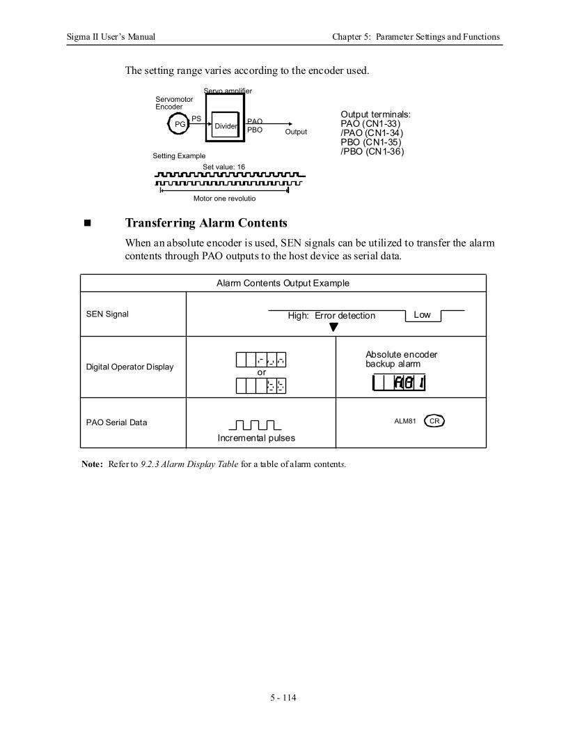
Sigma II User’s Manual Chapter 5: Parameter Settings and Functions
5 - 114
The setting range varies according to the encoder used.
Transferring Alarm Contents When an absolute encoder is used, SEN signals can be utilized to transfer the alarm contents through PAO outputs to the host device as serial data.
Note: Refer to 9.2.3 Alarm Display Table for a table of alarm contents.
Alarm Contents Output Example
SEN Signal
Digital Operator Display
PAO Serial Data
PG PAOOutput
PS
Servomotor Encoder
Servo amplifier
Divider PBO
Setting ExampleSet value: 16
Motor one revolution
Output terminals:PAO (CN1-33)/PAO (CN1-34)PBO (CN1-35)/PBO (CN1-36)
High: Error detection Low
or
Absolute encoderbackup alarm
Incremental pulses
CRALM81
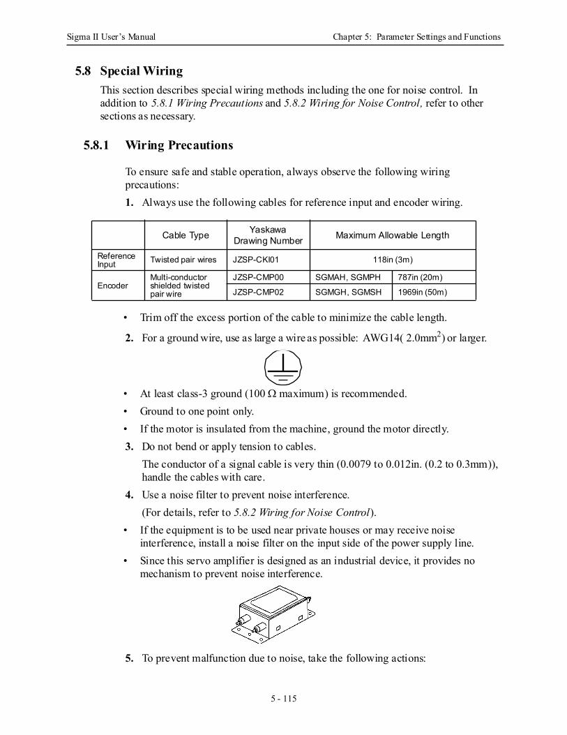
Sigma II User’s Manual Chapter 5: Parameter Settings and Functions
5 - 115
5.8 Special WiringThis section describes special wiring methods including the one for noise control. In addition to 5.8.1 Wiring Precautions and 5.8.2 Wiring for Noise Control, refer to other sections as necessary.
5.8.1 Wiring Precautions
To ensure safe and stable operation, always observe the following wiring precautions: 1. Always use the following cables for reference input and encoder wiring.
• Trim off the excess portion of the cable to minimize the cable length.
2. For a ground wire, use as large a wire as possible: AWG14( 2.0mm2) or larger.
• At least class-3 ground (100 Ω maximum) is recommended.• Ground to one point only.• If the motor is insulated from the machine, ground the motor directly.3. Do not bend or apply tension to cables.
The conductor of a signal cable is very thin (0.0079 to 0.012in. (0.2 to 0.3mm)), handle the cables with care.
4. Use a noise filter to prevent noise interference. (For details, refer to 5.8.2 Wiring for Noise Control).
• If the equipment is to be used near private houses or may receive noise interference, install a noise filter on the input side of the power supply line.
• Since this servo amplifier is designed as an industrial device, it provides no mechanism to prevent noise interference.
5. To prevent malfunction due to noise, take the following actions:
Cable Type Yaskawa Drawing Number Maximum Allowable Length
Reference Input Twisted pair wires JZSP-CKI01 118in (3m)
EncoderMulti-conductor shielded twisted pair wire
JZSP-CMP00 SGMAH, SGMPH 787in (20m)
JZSP-CMP02 SGMGH, SGMSH 1969in (50m)
Sigma II User’s Manual Chapter 5: Parameter Settings and Functions
5 - 116
• Position the input reference device and noise filter as close to the servo amplifier as possible.
• Always install a surge absorber circuit in the relay, solenoid, and electromagnetic contactor coils.
• The distance between a power line (such as a power supply line or motor cable) and a signal line must be at least 11.8in (30cm). Do not put the power and signal lines in the same duct or bundle them together.
• Do not share the power supply with an electric welder or electrical discharge machine. When the servo amplifier is placed near a high-frequency oscillator, install a noise filter on the input side of the power supply line.
Notes: 1. Since the servo amplifier uses high-speed switching elements, signal lines may receive noise.To prevent this, always take the above precautions.
2. For details on grounding and noise filters, refer to 5.8.2 Wiring for Noise Control.
6. Use a UL listed molded-case circuit breaker (MCCB) or fuse in accordance with the National Electrical Code (NEC) to protect the power supply line from high voltage.
• This servo amplifier connects directly to a commercial power supply without a transformer, so always use an MCCB or fuse to protect the servo system from accidental high voltage.
• Select an appropriate MCCB or fuse according to the servo amplifier capacity and the number of servo amplifiers to be used as shown in the following table.
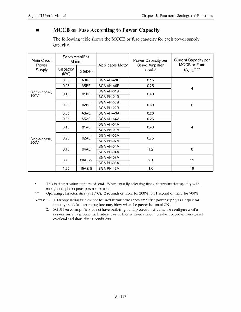
Sigma II User’s Manual Chapter 5: Parameter Settings and Functions
5 - 117
MCCB or Fuse According to Power Capacity The following table shows the MCCB or fuse capacity for each power supply capacity.
* This is the net value at the rated load. When actually selecting fuses, determine the capacity with enough margin for peak power operation.
** Operating characteristics (at 25°C): 2 seconds or more for 200%, 0.01 second or more for 700%
Notes: 1. A fast-operating fuse cannot be used because the servo amplifier power supply is a capacitor input type. A fast-operating fuse may blow when the power is turned ON.
2. SGDH servo amplifiers do not have built-in ground protection circuits. To configure a safer system, install a ground fault interrupter with or without a circuit breaker for protection against overload and short circuit conditions.
Main Circuit Power Supply
Servo Amplifier Model
Applicable MotorPower Capacity per
Servo Amplifier(kVA)*
Current Capacity per MCCB or Fuse
(Arm s)* **Capacity (kW) SGDH-
Single-phase, 100V
0.03 A3BE SGMAH-A3B 0.15
40.05 A5BE SGMAH-A5B 0.25
0.10 01BESGMAH-01B
0.40SGMPH-01B
0.20 02BESGMAH-02B
0.60 6SGMPH-02B
Single-phase, 200V
0.03 A3AE SGMAH-A3A 0.20
4
0.05 A5AE SGMAH-A5A 0.25
0.10 01AESGMAH-01A
0.40SGMPH-01A
0.20 02AESGMAH-02A
0.75SGMPH-02A
0.40 04AESGMAH-04A
1.2 8SGMPH-04A
0.75 08AE-SSGMAH-08A
2.1 11SGMPH-08A
1.50 15AE-S SGMPH-15A 4.0 19
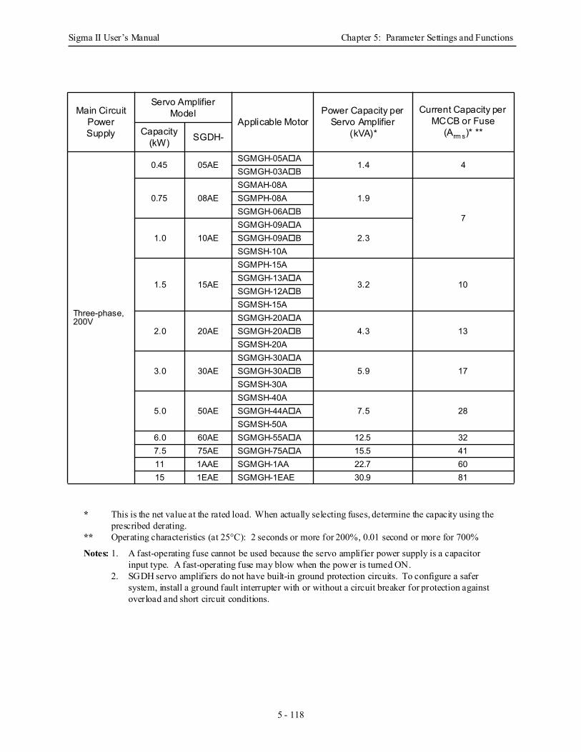
Sigma II User’s Manual Chapter 5: Parameter Settings and Functions
5 - 118
* This is the net value at the rated load. When actually selecting fuses, determine the capacity using the prescribed derating.
** Operating characteristics (at 25°C): 2 seconds or more for 200%, 0.01 second or more for 700%
Notes: 1. A fast-operating fuse cannot be used because the servo amplifier power supply is a capacitor input type. A fast-operating fuse may blow when the power is turned ON.
2. SGDH servo amplifiers do not have built-in ground protection circuits. To configure a safer system, install a ground fault interrupter with or without a circuit breaker for protection against overload and short circuit conditions.
Main Circuit Power Supply
Servo Amplifier Model
Applicable MotorPower Capacity per
Servo Amplifier(kVA)*
Current Capacity per MCCB or Fuse
(Arm s)* **Capacity (kW) SGDH-
Three-phase, 200V
0.45 05AESGMGH-05A A
1.4 4SGMGH-03A B
0.75 08AESGMAH-08A
1.9
7
SGMPH-08ASGMGH-06A B
1.0 10AESGMGH-09A A
2.3SGMGH-09A BSGMSH-10A
1.5 15AE
SGMPH-15A
3.2 10SGMGH-13A ASGMGH-12A BSGMSH-15A
2.0 20AESGMGH-20A A
4.3 13SGMGH-20A BSGMSH-20A
3.0 30AESGMGH-30A A
5.9 17SGMGH-30A BSGMSH-30A
5.0 50AESGMSH-40A
7.5 28SGMGH-44A ASGMSH-50A
6.0 60AE SGMGH-55A A 12.5 327.5 75AE SGMGH-75A A 15.5 4111 1AAE SGMGH-1AA 22.7 6015 1EAE SGMGH-1EAE 30.9 81
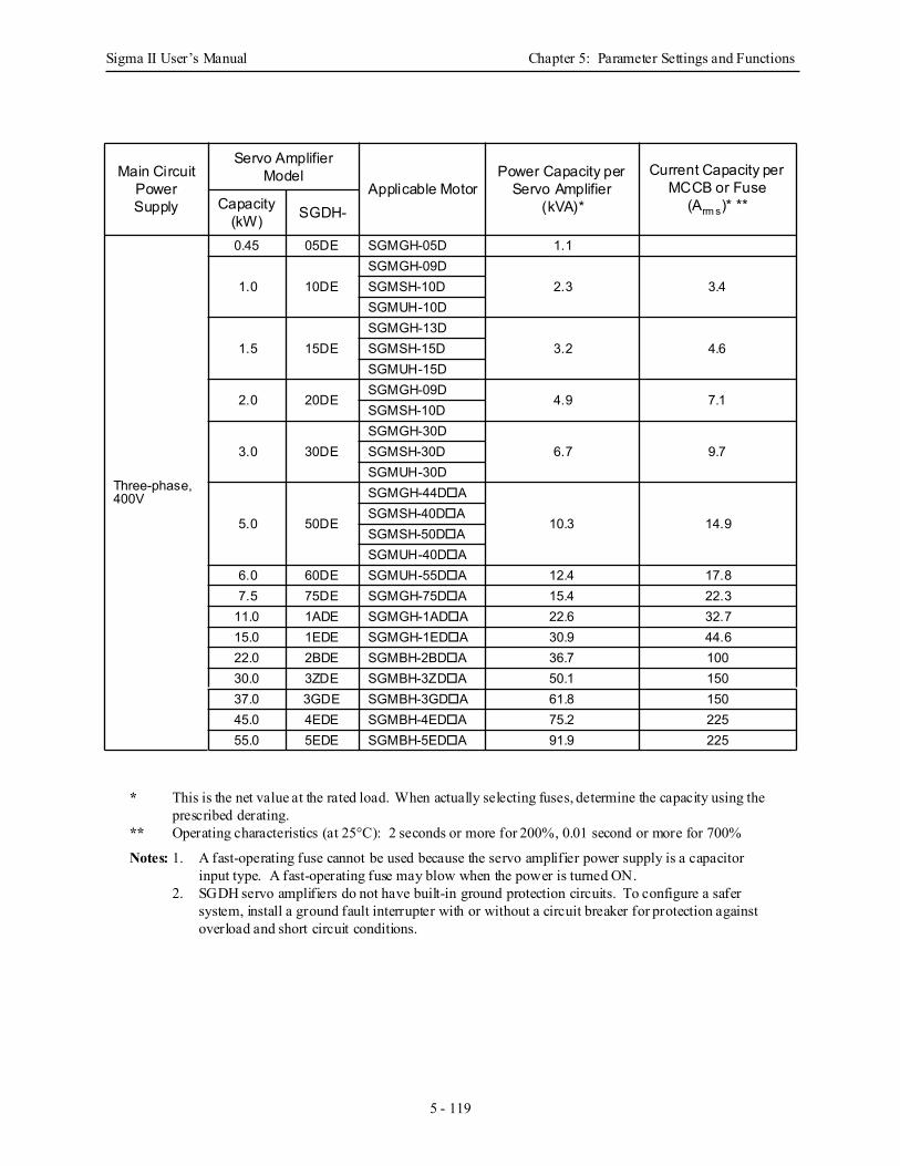
Sigma II User’s Manual Chapter 5: Parameter Settings and Functions
5 - 119
* This is the net value at the rated load. When actually selecting fuses, determine the capacity using the
prescribed derating.** Operating characteristics (at 25°C): 2 seconds or more for 200%, 0.01 second or more for 700%
Notes: 1. A fast-operating fuse cannot be used because the servo amplifier power supply is a capacitor input type. A fast-operating fuse may blow when the power is turned ON.
2. SGDH servo amplifiers do not have built-in ground protection circuits. To configure a safer system, install a ground fault interrupter with or without a circuit breaker for protection against overload and short circuit conditions.
Main Circuit Power Supply
Servo Amplifier Model
Applicable MotorPower Capacity per
Servo Amplifier(kVA)*
Current Capacity per MCCB or Fuse
(Arm s)* **Capacity (kW) SGDH-
Three-phase, 400V
0.45 05DE SGMGH-05D 1.1
1.0 10DESGMGH-09D
2.3 3.4SGMSH-10DSGMUH-10D
1.5 15DESGMGH-13D
3.2 4.6SGMSH-15DSGMUH-15D
2.0 20DESGMGH-09D
4.9 7.1SGMSH-10D
3.0 30DESGMGH-30D
6.7 9.7SGMSH-30DSGMUH-30D
5.0 50DE
SGMGH-44D A
10.3 14.9SGMSH-40D ASGMSH-50D ASGMUH-40D A
6.0 60DE SGMUH-55D A 12.4 17.87.5 75DE SGMGH-75D A 15.4 22.3
11.0 1ADE SGMGH-1AD A 22.6 32.715.0 1EDE SGMGH-1ED A 30.9 44.622.0 2BDE SGMBH-2BD A 36.7 10030.0 3ZDE SGMBH-3ZD A 50.1 15037.0 3GDE SGMBH-3GD A 61.8 15045.0 4EDE SGMBH-4ED A 75.2 22555.0 5EDE SGMBH-5ED A 91.9 225
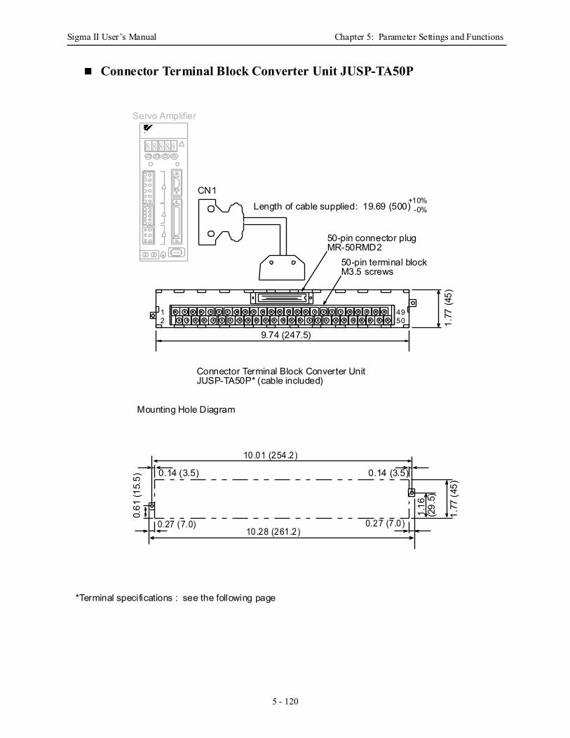
Sigma II User’s Manual Chapter 5: Parameter Settings and Functions
5 - 120
Connector Terminal Block Converter Unit JUSP-TA50P
4950
8 8 8 88
Servo Amplifier
Connector Terminal Block Converter UnitJUSP-TA50P* (cable included)
Length of cable supplied: 19.69 (500) -0%+10%
CN1
50-pin connector plugMR-50RMD2
50-pin terminal blockM3.5 screws
1.77
(45)
9.74 (247.5)
1.16
(29.
5)
Mounting Hole Diagram
10.28 (261.2)0.27 (7.0) 0.27 (7.0)
0.14 (3.5)0.14 (3.5)
1.77
(45)
10 .01 (254.2)
0.61
(15.
5)
12
*Terminal specifications : see the following page
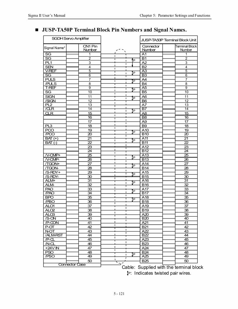
Sigma II User’s Manual Chapter 5: Parameter Settings and Functions
5 - 121
JUSP-TA50P Terminal Block Pin Numbers and Signal Names.
1234567891011121314151617181920212223242526272829303132333435363738394041424344454647484950
SGDH Servo Amplifier
Signal Name* CN1 PinNumber
SGSG
SENV-REF
PULS/PULS
SG
PL1
T-REFSGSIGN/SIGNPL2/CLRCLR
PL3PCO/PCOBAT (+)BAT (-)
/V-CMP+/V-CMP-/TGON+/TGON-/S-RDY+/S-RDY-ALM+ALM-PAO/PAOBPO/PBOALO1ALO2ALO3/S-ON/P-CONP-OTN-OT/ALM-RST/P-CL/N-CL+24V INPSO/PSO
1234567891011121314151617181920212223242526272829303132333435363738394041424344454647484950
JUSP-TA50P Terminal Block Unit
Connector Terminal BlockNumber
A1B1
B2A3
A4B4
B3
A2
A5B5A6B6A7B7A8
B9A10B10A11B11
A13B13A14B14A15B15A16B16A17B17A18B18A19B19A20B20A21B21A22B22A23B23A24B24A25
Number
B8A9
A12B12
B25
: Indicates twisted pair wires.P
P
P
P
P
P
P
P
P
P
P
P
P
P
P
P
Cable: Supplied with the terminal blockConnector Case
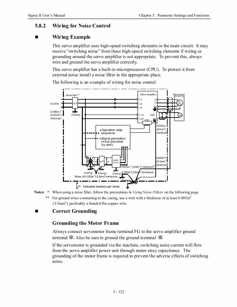
Sigma II User’s Manual Chapter 5: Parameter Settings and Functions
5 - 122
5.8.2 Wiring for Noise Control
Wiring ExampleThis servo amplifier uses high-speed switching elements in the main circuit. It may receive “switching noise” from these high-speed switching elements if wiring or grounding around the servo amplifier is not appropriate. To prevent this, always wire and ground the servo amplifier correctly.This servo amplifier has a built-in microprocessor (CPU). To protect it from external noise install a noise filter in the appropriate place. The following is an example of wiring for noise control.
Notes: * When using a noise filter, follow the precautions in Using Noise Filters on the following page.** For ground wires connecting to the casing, use a wire with a thickness of at least 0.005in2
(3.5mm2), preferably a braided flat copper wire.
Correct Grounding
Grounding the Motor Frame Always connect servomotor frame terminal FG to the servo amplifier ground terminal . Also be sure to ground the ground terminal .If the servomotor is grounded via the machine, switching noise current will flow from the servo amplifier power unit through motor stray capacitance. The grounding of the motor frame is required to prevent the adverse effects of switching noise.
M (FG)
U
WVL2
L1
L3
L2CL1C CN2
CN1
Servomotor
P
PP 1LF* AVR(Ground)
(Casing) (Casing)(Casing)
(Casing)
2LF
(Casing)
AC200V
PG
Noise filter*** Servo amplifier
P: Indicates twisted pair wires
•Operation relay sequence
•Signal generation circuit (provided by user)
0.003in. 2 (2mm 2) minimum**
0.003in.2
0.005in2(3.5mm2)minimum
(2mm2)minimum
0.005in2
(3.5mm 2)minimum
Wires of 0.005in 2(3.5mm2)minimum
0.005in.2(3.5mm2)minimum
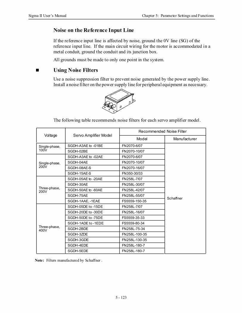
Sigma II User’s Manual Chapter 5: Parameter Settings and Functions
5 - 123
Noise on the Reference Input Line
If the reference input line is affected by noise, ground the 0V line (SG) of the reference input line. If the main circuit wiring for the motor is accommodated in a metal conduit, ground the conduit and its junction box.
All grounds must be made to only one point in the system.
Using Noise Filters Use a noise suppression filter to prevent noise generated by the power supply line. Install a noise filter on the power supply line for peripheral equipment as necessary.
The following table recommends noise filters for each servo amplifier model.
Note: Filters manufactured by Schaffner .
Voltage Servo Amplifier ModelRecommended Noise Filter
Model Manufacturer
Single-phase, 100V
SGDH-A3AE to -01BE FN2070-6/07
Schaffner
SGDH-02BE FN2070-10/07
Single-phase, 200V
SGDH-A3AE to -02AE FN2070-6/07SGDH-04AE FN2070-10/07SGDH-08AE-S FN2070-16/07SGDH-15AE-S FN350-30/33
Three-phase, 200V
SGDH-05AE to -20AE FN258L-7/07SGDH-30AE FN258L-30/07SGDH-50AE to -60AE FN258L-42/07SGDH-75AE FN258L-55/07SGDH-1AAE, -1EAE FS5559-150-35
Three-phase, 400V
SGDH-05DE to -15DE FN258L-7/07SGDH-20DE to -30DE FN258L-16/07SGDH-50DE to -75DE FS5559-35-33SGDH-1ADE to -1EDE FS5559-80-34SGDH-2BDE FN258L-75-34SGDH-3ZDE FN258L-100-35SGDH-3GDE FN258L-130-35SGDH-4EDE FN258L-180-7SGDH-5EDE FN258L-180-7
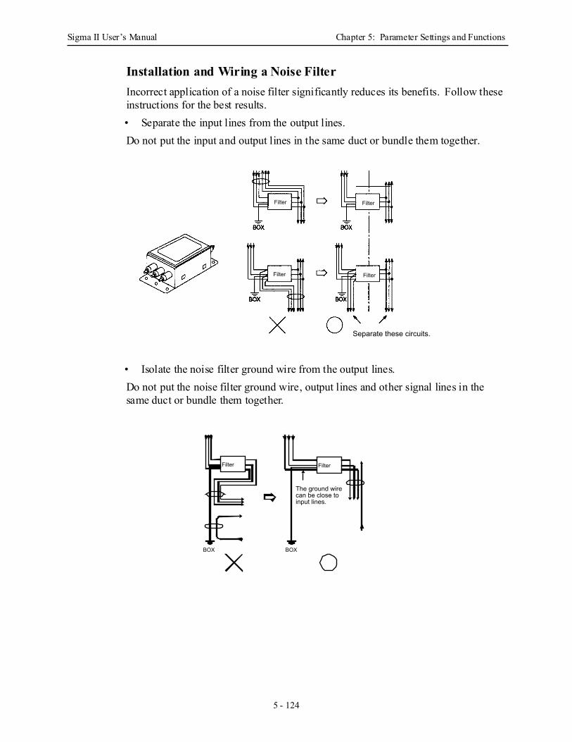
Sigma II User’s Manual Chapter 5: Parameter Settings and Functions
5 - 124
Installation and Wiring a Noise Filter Incorrect application of a noise filter significantly reduces its benefits. Follow these instructions for the best results. • Separate the input lines from the output lines. Do not put the input and output lines in the same duct or bundle them together.
• Isolate the noise filter ground wire from the output lines. Do not put the noise filter ground wire, output lines and other signal lines in the same duct or bundle them together.
Filter Filter
Filter Filter
Separate these circuits.
BOX BOX
The ground wire can be close to input lines.
Filter Filter
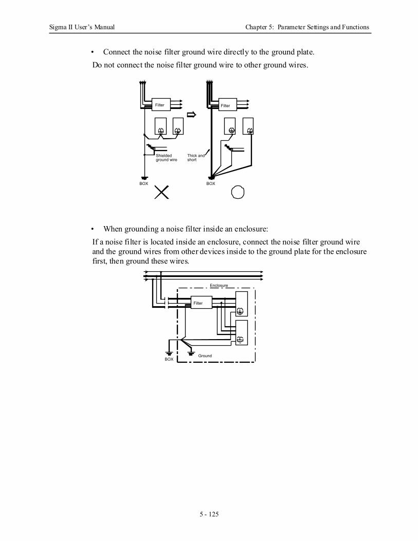
Sigma II User’s Manual Chapter 5: Parameter Settings and Functions
5 - 125
• Connect the noise filter ground wire directly to the ground plate. Do not connect the noise filter ground wire to other ground wires.
• When grounding a noise filter inside an enclosure: If a noise filter is located inside an enclosure, connect the noise filter ground wire and the ground wires from other devices inside to the ground plate for the enclosure first, then ground these wires.
BOX
Shielded ground wire
Thick and short
BOX
Filter Filter
Filter
Enclosure
GroundBOX
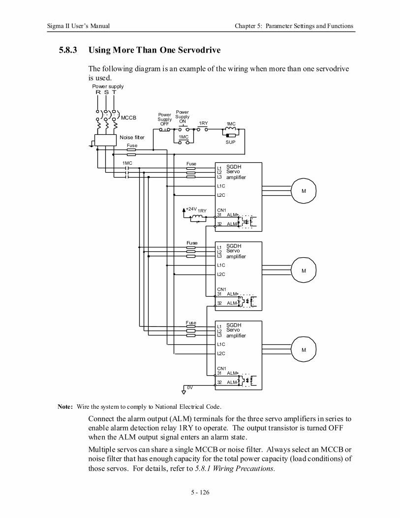
Sigma II User’s Manual Chapter 5: Parameter Settings and Functions
5 - 126
5.8.3 Using More Than One Servodrive
The following diagram is an example of the wiring when more than one servodrive is used.
Note: Wire the system to comply to National Electrical Code.
Connect the alarm output (ALM) terminals for the three servo amplifiers in series to enable alarm detection relay 1RY to operate. The output transistor is turned OFF when the ALM output signal enters an alarm state. Multiple servos can share a single MCCB or noise filter. Always select an MCCB or noise filter that has enough capacity for the total power capacity (load conditions) of those servos. For details, refer to 5.8.1 Wiring Precautions.
SGDHServoamplifier
L1L2L3
L1C
L2C
CN131 ALM+
32 ALM-
M
SGDHServoamplifier
L1L2L3
L1C
L2C
CN131 ALM+
32 ALM-
M
Fuse SGDHServoamplifier
L1L2L3
L1C
L2C
CN131 ALM+
32 ALM-
M
+24V 1RY
1MC
1MC
1MC1RY
Power PowerSupply
OFFSupply
ON
Fuse
Fuse
SUPNoise filter
MCCB
Power supplyR S T
Fuse
0V
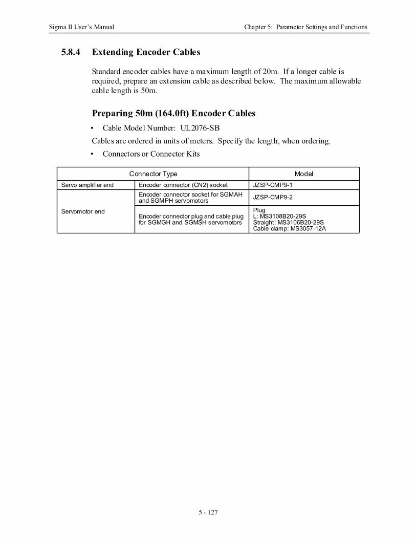
Sigma II User’s Manual Chapter 5: Parameter Settings and Functions
5 - 127
5.8.4 Extending Encoder Cables
Standard encoder cables have a maximum length of 20m. If a longer cable is required, prepare an extension cable as described below. The maximum allowable cable length is 50m.
Preparing 50m (164.0ft) Encoder Cables • Cable Model Number: UL2076-SB Cables are ordered in units of meters. Specify the length, when ordering.• Connectors or Connector Kits
Connector Type ModelServo amplifier end Encoder connector (CN2) socket JZSP-CMP9-1
Servomotor end
Encoder connector socket for SGMAH and SGMPH servomotors JZSP-CMP9-2
Encoder connector plug and cable plug for SGMGH and SGMSH servomotors
PlugL: MS3108B20-29SStraight: MS3106B20-29SCable clamp: MS3057-12A

Sigma II User’s Manual Chapter 5: Parameter Settings and Functions
5 - 128
• Preparing Encoder Cables
• Encoder Connector at Servo Amplifier
• Cable Line • Encoder Connector at Servomotor
For SGMAH and SGMPH servomotors
For SGMGH, SGMSH, and SGMUH servomo-tors
Maximum length: 50 m (1968.50 in)
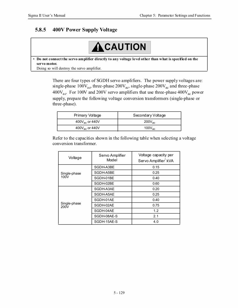
Sigma II User’s Manual Chapter 5: Parameter Settings and Functions
5 - 129
5.8.5 400V Power Supply Voltage
There are four types of SGDH servo amplifiers. The power supply voltages are: single-phase 100Vac, three-phase 200Vac, single-phase 200Vac and three-phase 400Vac. For 100V and 200V servo amplifiers that use three-phase 400Vac power supply, prepare the following voltage conversion transformers (single-phase or three-phase).
Refer to the capacities shown in the following table when selecting a voltage conversion transformer.
• Do not connect the servo amplifier directly to any voltage level other than what is specified on the servo motor.Doing so will destroy the servo amplifier.
Primary Voltage Secondary Voltage400Vac or 440V 200Vac
400Vac or 440V 100Vac
Voltage Servo Amplifier Model
Voltage capacity per Servo Amplifier* kVA
Single-phase 100V
SGDH-A3BE 0.15SGDH-A5BE 0.25SGDH-01BE 0.40SGDH-02BE 0.60
Single-phase 200V
SGDH-A3AE 0.20SGDH-A5AE 0.25SGDH-01AE 0.40SGDH-02AE 0.75SGDH-04AE 1.2SGDH-08AE-S 2.1SGDH-15AE-S 4.0
CAUTION
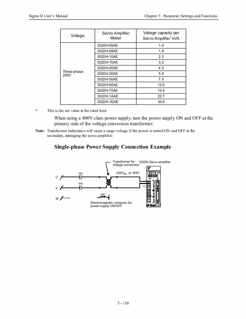
Sigma II User’s Manual Chapter 5: Parameter Settings and Functions
5 - 130
* This is the net value at the rated load.
When using a 400V class power supply, turn the power supply ON and OFF at the primary side of the voltage conversion transformer.
Note: Transformer inductance will cause a surge voltage if the power is turned ON and OFF at the secondary, damaging the servo amplifier.
Single-phase Power Supply Connection Example
Three-phase 200V
SGDH-05AE 1.4SGDH-08AE 1.9SGDH-10AE 2.3SGDH-15AE 3.2SGDH-20AE 4.3SGDH-30AE 5.9SGDH-50AE 7.5SGDH-60AE 12.5SGDH-75AE 15.5SGDH-1AAE 22.7SGDH-1EAE 30.9
Voltage Servo Amplifier Model
Voltage capacity per Servo Amplifier* kVA
U
V
W
1MC
1MC
1MC
Electromagnetic contactor for power supply ON/OFF
Transformer for voltage conversion
L1
L2
SGDH Servo amplifier
200VAC or 100V
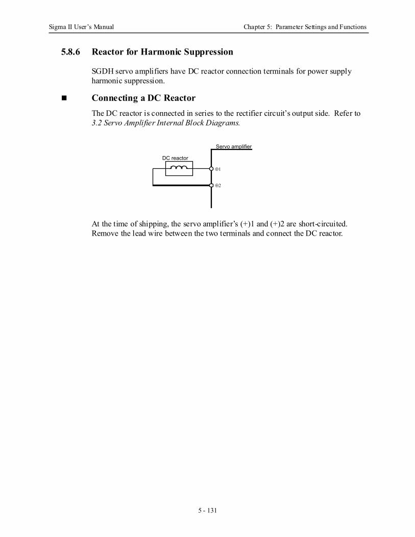
Sigma II User’s Manual Chapter 5: Parameter Settings and Functions
5 - 131
5.8.6 Reactor for Harmonic Suppression
SGDH servo amplifiers have DC reactor connection terminals for power supply harmonic suppression.
Connecting a DC Reactor The DC reactor is connected in series to the rectifier circuit’s output side. Refer to 3.2 Servo Amplifier Internal Block Diagrams.
At the time of shipping, the servo amplifier’s (+)1 and (+)2 are short-circuited. Remove the lead wire between the two terminals and connect the DC reactor.
Servo amplifier
DC reactor
⊕1
⊕2
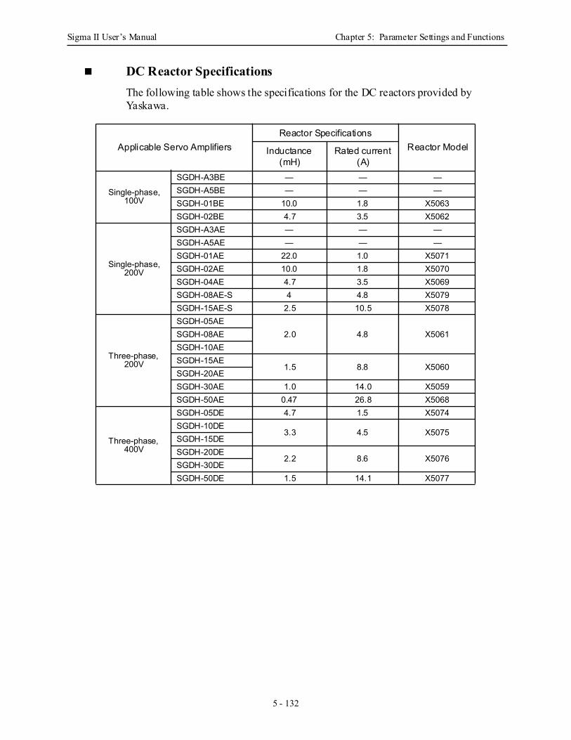
Sigma II User’s Manual Chapter 5: Parameter Settings and Functions
5 - 132
DC Reactor Specifications The following table shows the specifications for the DC reactors provided by Yaskawa.
Applicable Servo AmplifiersReactor Specifications
Reactor ModelInductance(mH)
Rated current(A)
Single-phase, 100V
SGDH-A3BE — — —SGDH-A5BE — — —SGDH-01BE 10.0 1.8 X5063SGDH-02BE 4.7 3.5 X5062
Single-phase, 200V
SGDH-A3AE — — —SGDH-A5AE — — —SGDH-01AE 22.0 1.0 X5071SGDH-02AE 10.0 1.8 X5070SGDH-04AE 4.7 3.5 X5069SGDH-08AE-S 4 4.8 X5079SGDH-15AE-S 2.5 10.5 X5078
Three-phase, 200V
SGDH-05AE2.0 4.8 X5061SGDH-08AE
SGDH-10AESGDH-15AE
1.5 8.8 X5060SGDH-20AESGDH-30AE 1.0 14.0 X5059SGDH-50AE 0.47 26.8 X5068
Three-phase, 400V
SGDH-05DE 4.7 1.5 X5074SGDH-10DE
3.3 4.5 X5075SGDH-15DESGDH-20DE
2.2 8.6 X5076SGDH-30DESGDH-50DE 1.5 14.1 X5077
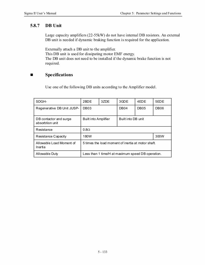
Sigma II User’s Manual Chapter 5: Parameter Settings and Functions
5 - 133
5.8.7 DB Unit
Large capacity amplifiers (22-55kW) do not have internal DB resistors. An external DB unit is needed if dynamic braking function is required for the application.
Externally attach a DB unit to the amplifier.This DB unit is used for dissipating motor EMF energy.The DB unit does not need to be installed if the dynamic brake function is not required.
Specifications
Use one of the following DB units according to the Amplifier model.
SDGH- 2BDE 3ZDE 3GDE 4EDE 5EDE
Regenerative DB Unit JUSP- DB03 DB04 DB05 DB06
DB contactor and surge absorbtion unit
Built into Amplifier Built into DB unit
Resistance 0.8Ω
Resistance Capacity 180W 300W
Allowable Load Moment of Inertia
5 times the load moment of inertia at motor shaft.
Allowable Duty Less than 1 time/H at maximum speed DB operation.
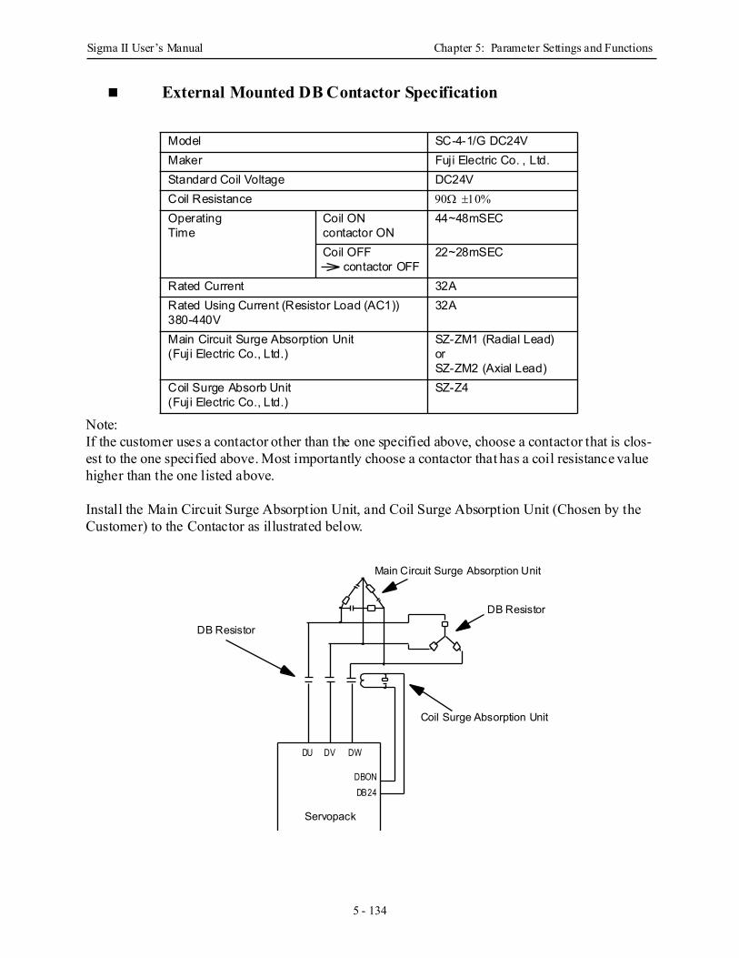
Sigma II User’s Manual Chapter 5: Parameter Settings and Functions
5 - 134
External Mounted DB Contactor Specification
Note:If the customer uses a contactor other than the one specified above, choose a contactor that is clos-est to the one specified above. Most importantly choose a contactor that has a coil resistance value higher than the one listed above.
Install the Main Circuit Surge Absorption Unit, and Coil Surge Absorption Unit (Chosen by the Customer) to the Contactor as illustrated below.
Model SC-4-1/G DC24VMaker Fuji Electric Co. , Ltd.Standard Coil Voltage DC24VCoil Resistance 90Ω ±10%
Operating Time
Coil ONcontactor ON
44~48mSEC
Coil OFF contactor OFF
22~28mSEC
Rated Current 32ARated Using Current (Resistor Load (AC1))380-440V
32A
Main Circuit Surge Absorption Unit(Fuji Electric Co., Ltd.)
SZ-ZM1 (Radial Lead)orSZ-ZM2 (Axial Lead)
Coil Surge Absorb Unit(Fuji Electric Co., Ltd.)
SZ-Z4
Main Circuit Surge Absorption Unit
DB Resistor
Coil Surge Absorption Unit
DB Resistor
Servopack
DU DV DW
DBONDB24
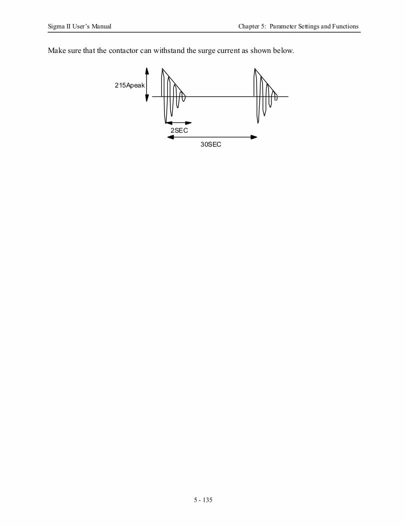
Sigma II User’s Manual Chapter 5: Parameter Settings and Functions
5 - 135
Make sure that the contactor can withstand the surge current as shown below.
215Apeak
2SEC
30SEC
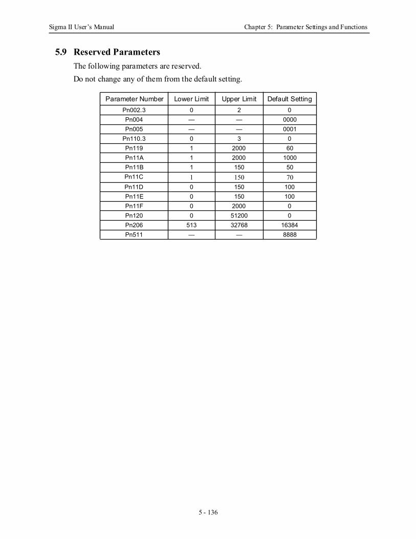
Sigma II User’s Manual Chapter 5: Parameter Settings and Functions
5 - 136
5.9 Reserved ParametersThe following parameters are reserved.Do not change any of them from the default setting.
Parameter Number Lower Limit Upper Limit Default SettingPn002.3 0 2 0Pn004 — — 0000Pn005 — — 0001
Pn110.3 0 3 0Pn119 1 2000 60Pn11A 1 2000 1000Pn11B 1 150 50Pn11C 1 150 70Pn11D 0 150 100Pn11E 0 150 100Pn11F 0 2000 0Pn120 0 51200 0Pn206 513 32768 16384Pn511 — — 8888
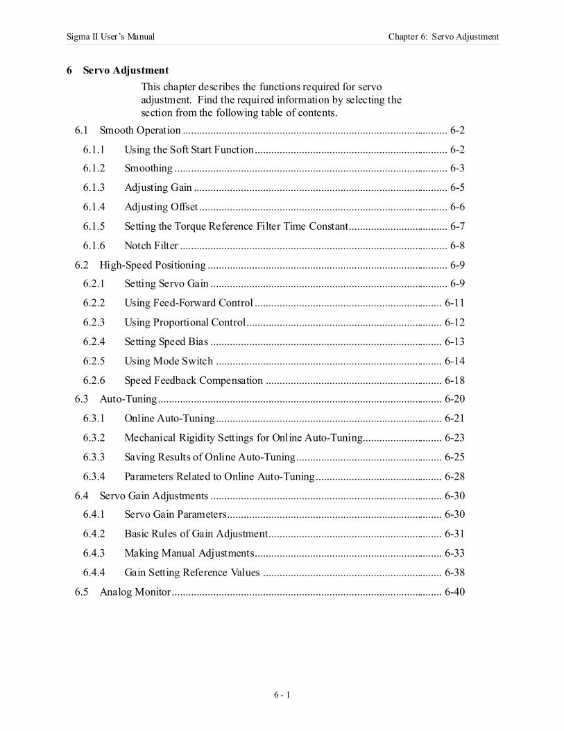
Sigma II User’s Manual Chapter 6: Servo Adjustment
6 - 1
6 Servo AdjustmentThis chapter describes the functions required for servo adjustment. Find the required information by selecting the section from the following table of contents.
6.1 Smooth Operation ................................................................................................ 6-2
6.1.1 Using the Soft Start Function...................................................................... 6-2
6.1.2 Smoothing ................................................................................................... 6-3
6.1.3 Adjusting Gain ............................................................................................ 6-5
6.1.4 Adjusting Offset .......................................................................................... 6-6
6.1.5 Setting the Torque Reference Filter Time Constant.................................... 6-7
6.1.6 Notch Filter ................................................................................................. 6-8
6.2 High-Speed Positioning ....................................................................................... 6-9
6.2.1 Setting Servo Gain ...................................................................................... 6-9
6.2.2 Using Feed-Forward Control .................................................................... 6-11
6.2.3 Using Proportional Control....................................................................... 6-12
6.2.4 Setting Speed Bias .................................................................................... 6-13
6.2.5 Using Mode Switch .................................................................................. 6-14
6.2.6 Speed Feedback Compensation ................................................................ 6-18
6.3 Auto-Tuning....................................................................................................... 6-20
6.3.1 Online Auto-Tuning.................................................................................. 6-21
6.3.2 Mechanical Rigidity Settings for Online Auto-Tuning............................. 6-23
6.3.3 Saving Results of Online Auto-Tuning..................................................... 6-25
6.3.4 Parameters Related to Online Auto-Tuning.............................................. 6-28
6.4 Servo Gain Adjustments .................................................................................... 6-30
6.4.1 Servo Gain Parameters.............................................................................. 6-30
6.4.2 Basic Rules of Gain Adjustment............................................................... 6-31
6.4.3 Making Manual Adjustments.................................................................... 6-33
6.4.4 Gain Setting Reference Values ................................................................. 6-38
6.5 Analog Monitor.................................................................................................. 6-40
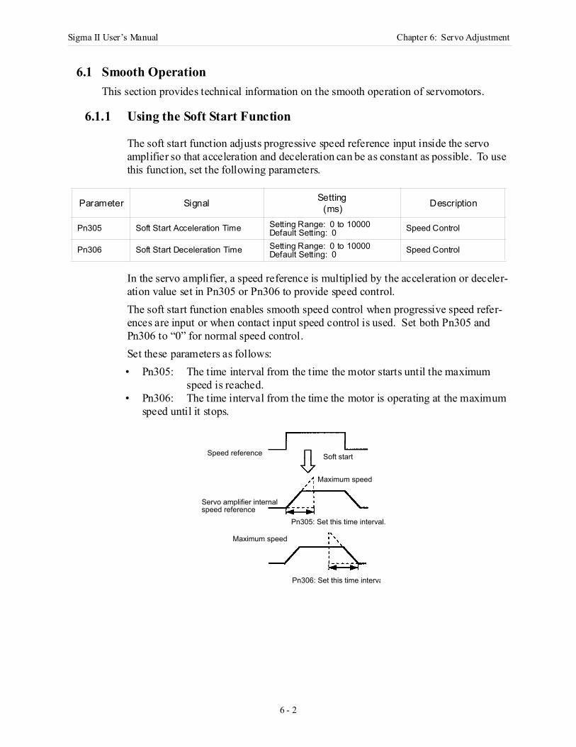
Sigma II User’s Manual Chapter 6: Servo Adjustment
6 - 2
6.1 Smooth OperationThis section provides technical information on the smooth operation of servomotors.
6.1.1 Using the Soft Start Function
The soft start function adjusts progressive speed reference input inside the servo amplifier so that acceleration and deceleration can be as constant as possible. To use this function, set the following parameters.
In the servo amplifier, a speed reference is multiplied by the acceleration or deceler-ation value set in Pn305 or Pn306 to provide speed control.The soft start function enables smooth speed control when progressive speed refer-ences are input or when contact input speed control is used. Set both Pn305 and Pn306 to “0” for normal speed control.Set these parameters as follows:• Pn305: The time interval from the time the motor starts until the maximum
speed is reached.• Pn306: The time interval from the time the motor is operating at the maximum
speed until it stops.
Parameter Signal Setting(ms) Description
Pn305 Soft Start Acceleration Time Setting Range: 0 to 10000Default Setting: 0 Speed Control
Pn306 Soft Start Deceleration Time Setting Range: 0 to 10000Default Setting: 0 Speed Control
Speed reference Soft start
Maximum speed
Servo amplifier internal speed reference
Pn305: Set this time interval.
Pn306: Set this time interva
Maximum speed
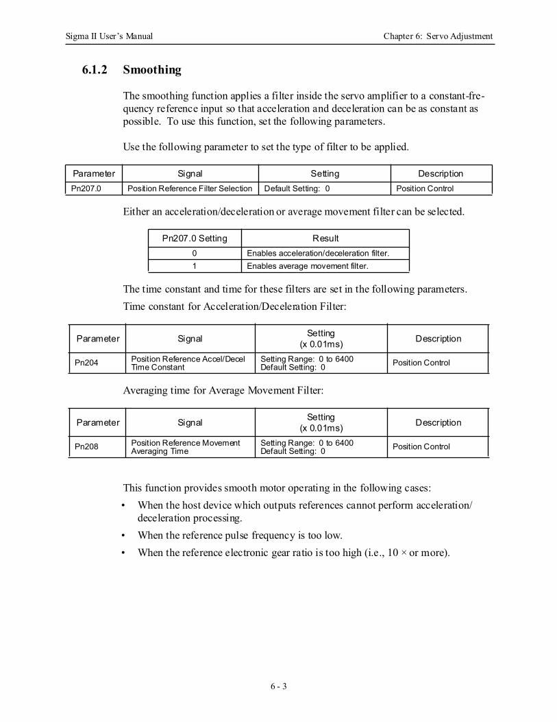
Sigma II User’s Manual Chapter 6: Servo Adjustment
6 - 3
6.1.2 Smoothing
The smoothing function applies a filter inside the servo amplifier to a constant-fre-quency reference input so that acceleration and deceleration can be as constant as possible. To use this function, set the following parameters.
Use the following parameter to set the type of filter to be applied.
Either an acceleration/deceleration or average movement filter can be selected.
The time constant and time for these filters are set in the following parameters.Time constant for Acceleration/Deceleration Filter:
Averaging time for Average Movement Filter:
This function provides smooth motor operating in the following cases:• When the host device which outputs references cannot perform acceleration/
deceleration processing.• When the reference pulse frequency is too low.• When the reference electronic gear ratio is too high (i.e., 10 × or more).
Parameter Signal Setting DescriptionPn207.0 Position Reference Filter Selection Default Setting: 0 Position Control
Pn207.0 Setting Result0 Enables acceleration/deceleration filter.1 Enables average movement filter.
Parameter Signal Setting(x 0.01ms) Description
Pn204 Position Reference Accel/Decel Time Constant
Setting Range: 0 to 6400Default Setting: 0 Position Control
Parameter Signal Setting(x 0.01ms) Description
Pn208 Position Reference Movement Averaging Time
Setting Range: 0 to 6400Default Setting: 0 Position Control
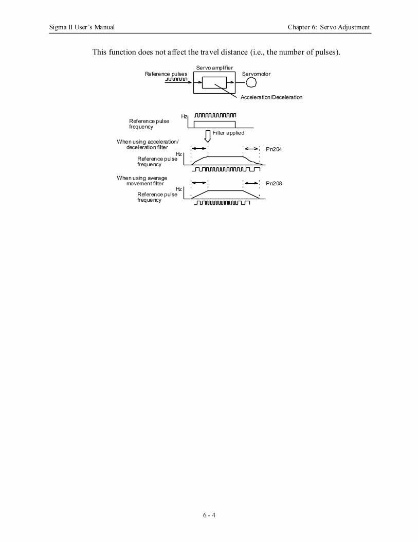
Sigma II User’s Manual Chapter 6: Servo Adjustment
6 - 4
This function does not affect the travel distance (i.e., the number of pulses).
ServomotorServo amplif ier
Acceleration/Deceleration
Reference pulses
Reference pulsefrequency
Hz
Filter applied
Pn204
Pn208Hz
Hz
Reference pulsefrequency
Reference pulsefrequency
When using acceleration/deceleration f ilter
When using averagemovement filter

Sigma II User’s Manual Chapter 6: Servo Adjustment
6 - 5
6.1.3 Adjusting Gain
If speed loop gain or position loop gain exceeds the allowable limit for the servo sys-tem (including the machine to be controlled), the system will tend to vibrate or become too sensitive. Smooth operation is not possible under such conditions. Reduce each loop gain value to an appropriate value.
Refer to 6.2.1 Setting Servo Gain for details regarding servo gain adjustment.
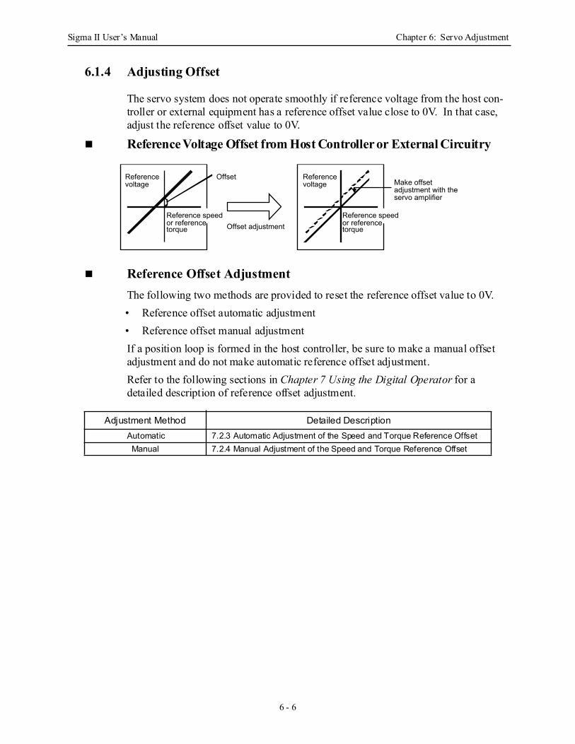
Sigma II User’s Manual Chapter 6: Servo Adjustment
6 - 6
6.1.4 Adjusting Offset
The servo system does not operate smoothly if reference voltage from the host con-troller or external equipment has a reference offset value close to 0V. In that case, adjust the reference offset value to 0V.
Reference Voltage Offset from Host Controller or External Circuitry
Reference Offset Adjustment The following two methods are provided to reset the reference offset value to 0V. • Reference offset automatic adjustment• Reference offset manual adjustment
If a position loop is formed in the host controller, be sure to make a manual offset adjustment and do not make automatic reference offset adjustment.
Refer to the following sections in Chapter 7 Using the Digital Operator for a detailed description of reference offset adjustment.
Adjustment Method Detailed DescriptionAutomatic 7.2.3 Automatic Adjustment of the Speed and Torque Reference OffsetManual 7.2.4 Manual Adjustment of the Speed and Torque Reference Offset
Offset
Offset adjustment Reference speed or reference torque
Reference voltage
Reference voltage
Reference speed or reference torque
Make offset adjustment with the servo amplifier

Sigma II User’s Manual Chapter 6: Servo Adjustment
6 - 7
6.1.5 Setting the Torque Reference Filter Time Constant
If there is machine vibration which may be caused by the servodrive, try adjusting the filter time constant in Pn401. This may stop the vibration.
The above constant is the filter time constant of the torque reference to be set in the servo amplifier. The smaller the value, the faster the speed control response will be. There is, however, a limit, depending on machine conditions.
Parameter Signal Setting(x 0.01ms) Application
Pn401 Torque Reference Filter Time Constant
Setting Range: 0 to 65535Default Setting: 100
Speed/Torque Control, Position Control
Sigma II User’s Manual Chapter 6: Servo Adjustment
6 - 8
6.1.6 Notch Filter
Vibration in the machine can sometimes be eliminated by using a notch filter for the frequency at which the vibration is occurring.
This parameter can be set to enable the notch filter.
Use the following parameter to set the frequency at which the filter is effective.
Parameter Signal Setting Description
Pn408.0 Notch Filter Selection Default Setting: 0 Speed/Torque Control, Position Control
Pn408.0 Setting Result0 None.1 Enables notch filter for torque reference.
Parameter Signal Setting(Hz) Description
Pn409 Notch Filter Frequency Setting Range: 50 to 2000Default Setting: 2000
Speed/Torque Control, Position Control
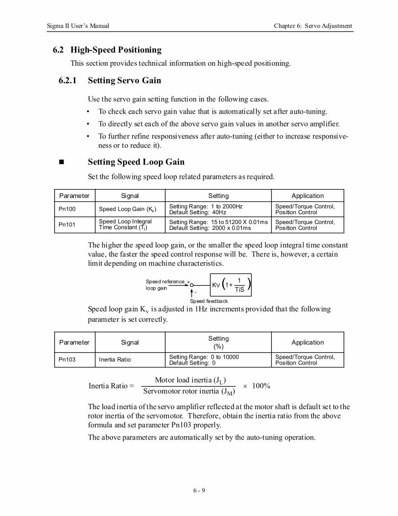
Sigma II User’s Manual Chapter 6: Servo Adjustment
6 - 9
6.2 High-Speed PositioningThis section provides technical information on high-speed positioning.
6.2.1 Setting Servo Gain
Use the servo gain setting function in the following cases.• To check each servo gain value that is automatically set after auto-tuning.• To directly set each of the above servo gain values in another servo amplifier.• To further refine responsiveness after auto-tuning (either to increase responsive-
ness or to reduce it).
Setting Speed Loop Gain Set the following speed loop related parameters as required.
The higher the speed loop gain, or the smaller the speed loop integral time constant value, the faster the speed control response will be. There is, however, a certain limit depending on machine characteristics.
Speed loop gain Kv is adjusted in 1Hz increments provided that the following parameter is set correctly.
The load inertia of the servo amplifier reflected at the motor shaft is default set to the rotor inertia of the servomotor. Therefore, obtain the inertia ratio from the above formula and set parameter Pn103 properly. The above parameters are automatically set by the auto-tuning operation.
Parameter Signal Setting Application
Pn100 Speed Loop Gain (Kv) Setting Range: 1 to 2000HzDefault Setting: 40Hz
Speed/Torque Control, Position Control
Pn101 Speed Loop Integral Time Constant (Ti)
Setting Range: 15 to 51200 X 0.01msDefault Setting: 2000 x 0.01ms
Speed/Torque Control, Position Control
Parameter Signal Setting(%) Application
Pn103 Inertia Ratio Setting Range: 0 to 10000Default Setting: 0
Speed/Torque Control, Position Control
KV (1+ )1TiSloop gain
Speed feedback
Speed reference +
-
Inertia Ratio = × 100%Motor load inertia (JL)
Servomotor rotor inertia (JM)
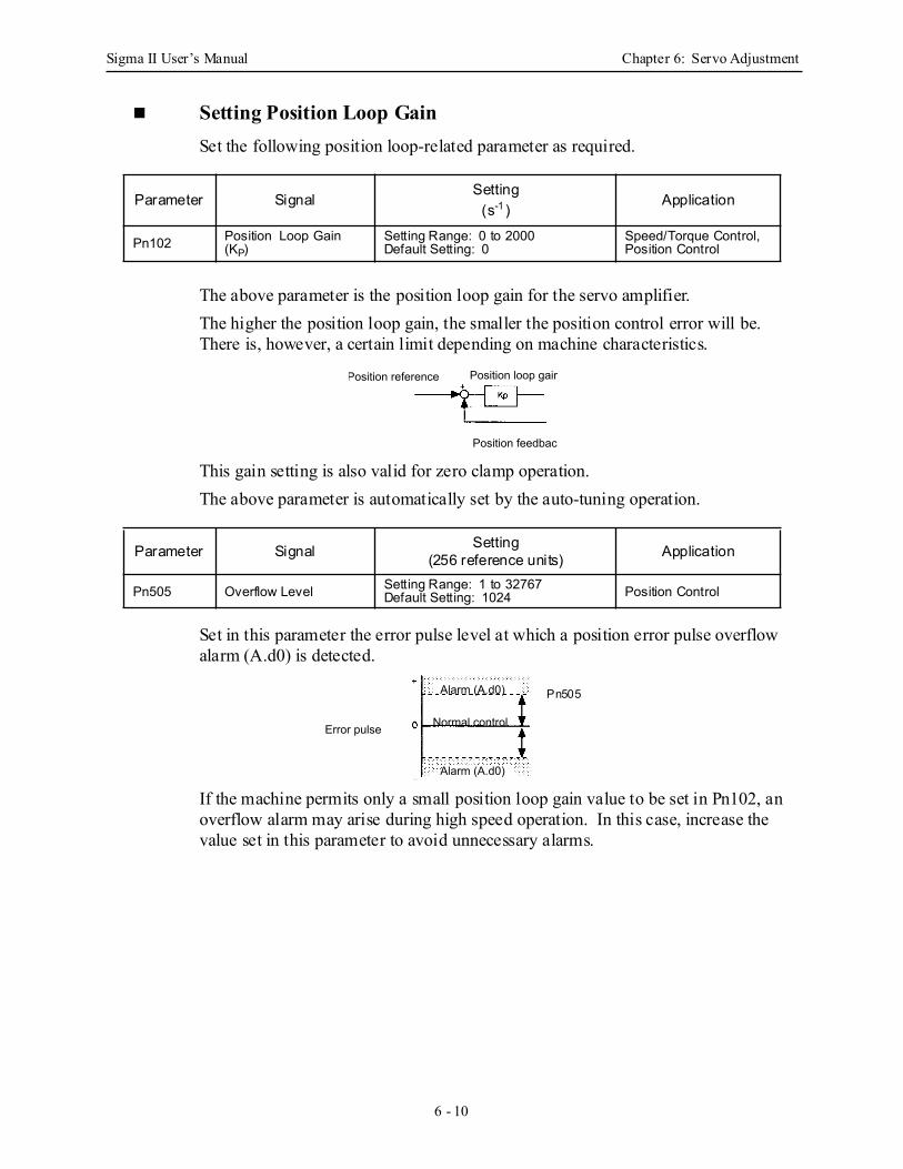
Sigma II User’s Manual Chapter 6: Servo Adjustment
6 - 10
Setting Position Loop Gain Set the following position loop-related parameter as required.
The above parameter is the position loop gain for the servo amplifier.The higher the position loop gain, the smaller the position control error will be. There is, however, a certain limit depending on machine characteristics.
This gain setting is also valid for zero clamp operation.The above parameter is automatically set by the auto-tuning operation.
Set in this parameter the error pulse level at which a position error pulse overflow alarm (A.d0) is detected.
If the machine permits only a small position loop gain value to be set in Pn102, an overflow alarm may arise during high speed operation. In this case, increase the value set in this parameter to avoid unnecessary alarms.
Parameter SignalSetting
(s-1 )Application
Pn102 Position Loop Gain (KP)
Setting Range: 0 to 2000Default Setting: 0
Speed/Torque Control, Position Control
Parameter Signal Setting(256 reference units) Application
Pn505 Overflow Level Setting Range: 1 to 32767Default Setting: 1024 Position Control
Position reference Position loop gain
Position feedback
Normal controlError pulse
Alarm (A.d0)
Alarm (A.d0)
Pn505
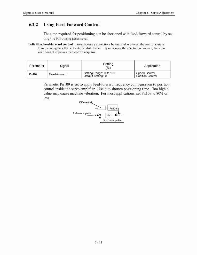
Sigma II User’s Manual Chapter 6: Servo Adjustment
6 - 11
6.2.2 Using Feed-Forward Control
The time required for positioning can be shortened with feed-forward control by set-ting the following parameter.
Definition:Feed-forward control makes necessary corrections beforehand to prevent the control system from receiving the effects of external disturbance. By increasing the effective servo gain, feed-for-ward control improves the system’s response.
Parameter Pn109 is set to apply feed-forward frequency compensation to position control inside the servo amplifier. Use it to shorten positioning time. Too high a value may cause machine vibration. For most applications, set Pn109 to 80% or less.
Parameter Signal Setting(%) Application
Pn109 Feed-forward Setting Range: 0 to 100Default Setting: 0
Speed Control,Position Control
Reference pulse
Pn109
Differential
Feedback pulse
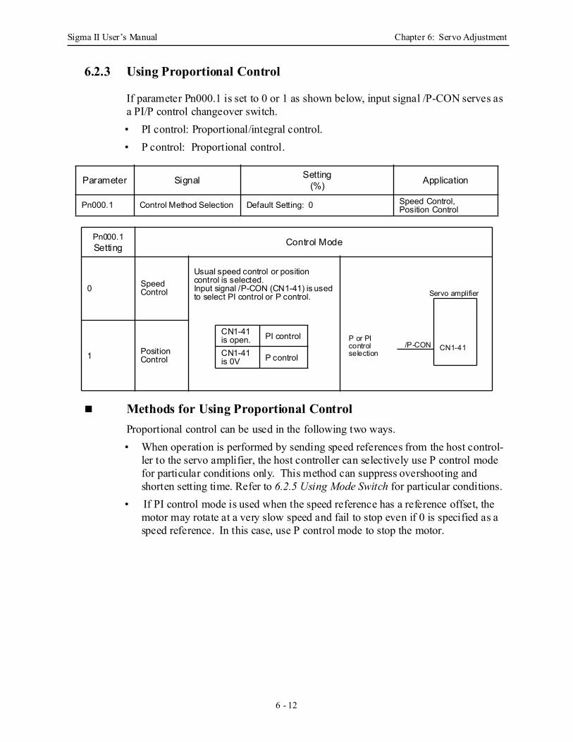
Sigma II User’s Manual Chapter 6: Servo Adjustment
6 - 12
6.2.3 Using Proportional Control
If parameter Pn000.1 is set to 0 or 1 as shown below, input signal /P-CON serves as a PI/P control changeover switch.• PI control: Proportional/integral control. • P control: Proportional control.
Methods for Using Proportional ControlProportional control can be used in the following two ways.• When operation is performed by sending speed references from the host control-
ler to the servo amplifier, the host controller can selectively use P control mode for particular conditions only. This method can suppress overshooting and shorten setting time. Refer to 6.2.5 Using Mode Switch for particular conditions.
• If PI control mode is used when the speed reference has a reference offset, the motor may rotate at a very slow speed and fail to stop even if 0 is specified as a speed reference. In this case, use P control mode to stop the motor.
Parameter Signal Setting(%) Application
Pn000.1 Control Method Selection Default Setting: 0 Speed Control,Position Control
Pn000.1 Setting Control Mode
0 Speed Control
Usual speed control or position control is selected. Input signal /P-CON (CN1-41) is used to select PI control or P control.
1 Position Control
CN1-41 is open. PI control
CN1-41 is 0V P control
P or PIcontrolselection
CN1-41/P-CON
Servo amplifier
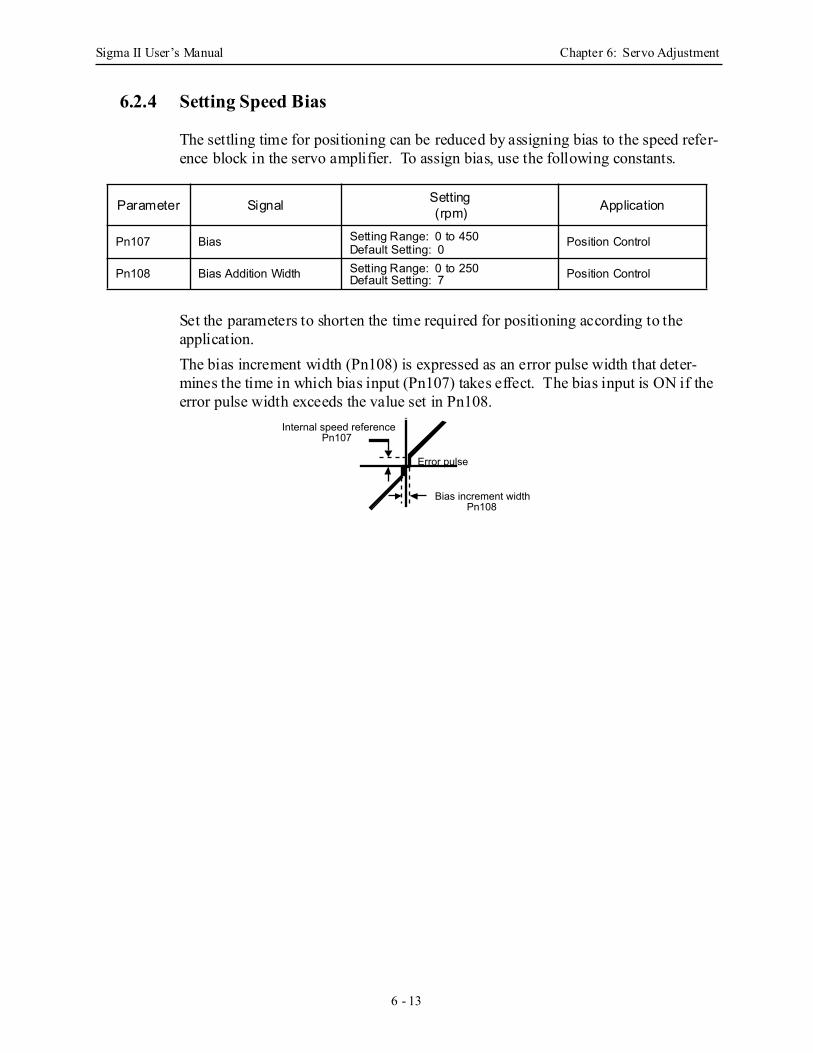
Sigma II User’s Manual Chapter 6: Servo Adjustment
6 - 13
6.2.4 Setting Speed Bias
The settling time for positioning can be reduced by assigning bias to the speed refer-ence block in the servo amplifier. To assign bias, use the following constants.
Set the parameters to shorten the time required for positioning according to the application.The bias increment width (Pn108) is expressed as an error pulse width that deter-mines the time in which bias input (Pn107) takes effect. The bias input is ON if the error pulse width exceeds the value set in Pn108.
Parameter Signal Setting(rpm) Application
Pn107 Bias Setting Range: 0 to 450Default Setting: 0 Position Control
Pn108 Bias Addition Width Setting Range: 0 to 250Default Setting: 7 Position Control
Error pulse
Internal speed referencePn107
Bias increment widthPn108
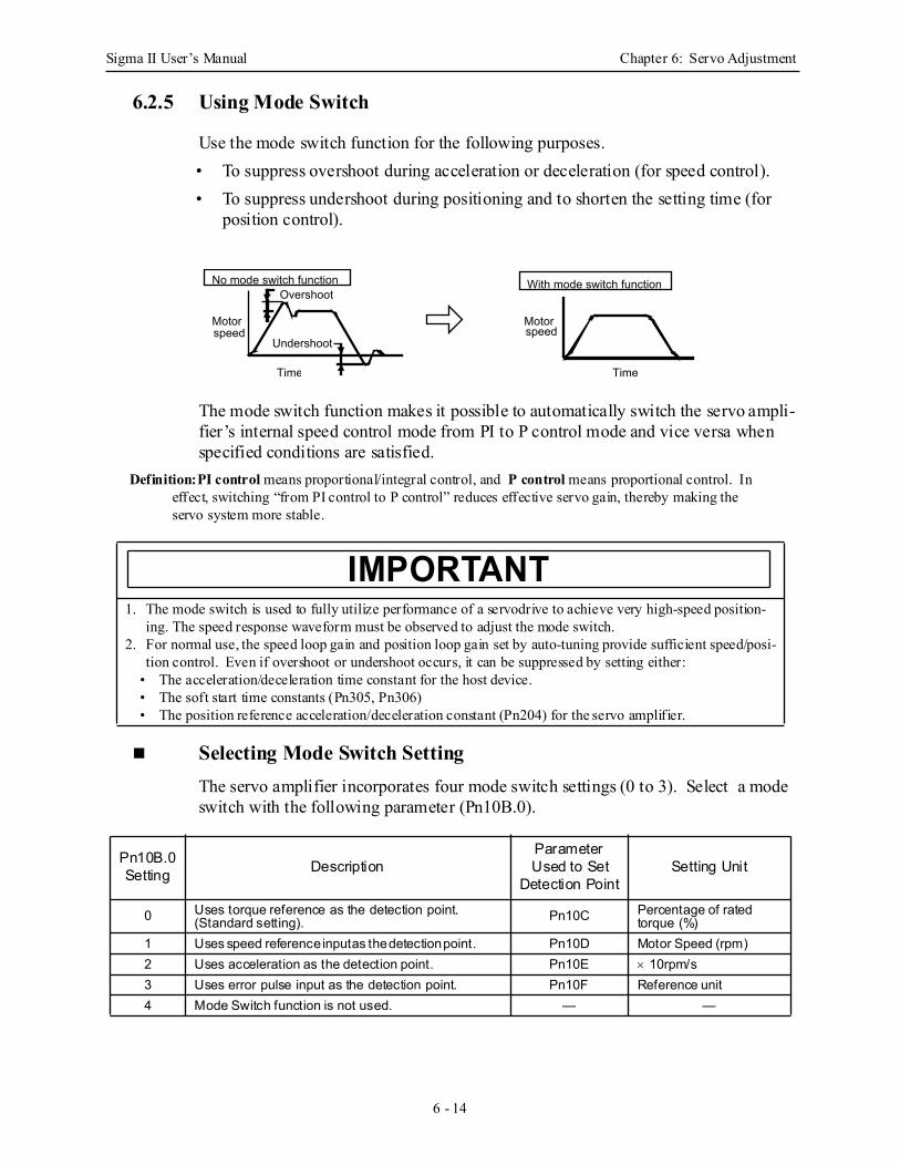
Sigma II User’s Manual Chapter 6: Servo Adjustment
6 - 14
6.2.5 Using Mode Switch
Use the mode switch function for the following purposes.• To suppress overshoot during acceleration or deceleration (for speed control).• To suppress undershoot during positioning and to shorten the setting time (for
position control).
The mode switch function makes it possible to automatically switch the servo ampli-fier’s internal speed control mode from PI to P control mode and vice versa when specified conditions are satisfied.
Definition:PI control means proportional/integral control, and P control means proportional control. In effect, switching “from PI control to P control” reduces effective servo gain, thereby making the servo system more stable.
Selecting Mode Switch Setting The servo amplifier incorporates four mode switch settings (0 to 3). Select a mode switch with the following parameter (Pn10B.0).
1. The mode switch is used to fully utilize performance of a servodrive to achieve very high-speed position-ing. The speed response waveform must be observed to adjust the mode switch.
2. For normal use, the speed loop gain and position loop gain set by auto-tuning provide sufficient speed/posi-tion control. Even if overshoot or undershoot occurs, it can be suppressed by setting either:
• The acceleration/deceleration time constant for the host device.• The soft start time constants (Pn305, Pn306)• The position reference acceleration/deceleration constant (Pn204) for the servo amplifier.
Pn10B.0Setting Description
Parameter Used to Set
Detection PointSetting Unit
0 Uses torque reference as the detection point. (Standard setting). Pn10C Percentage of rated
torque (%)1 Uses speed reference input as the detection point. Pn10D Motor Speed (rpm)2 Uses acceleration as the detection point. Pn10E × 10rpm/s3 Uses error pulse input as the detection point. Pn10F Reference unit4 Mode Switch function is not used. — —
Overshoot
Undershoot
Motor speed
Time
No mode switch function With mode switch function
Motor speed
Time
IMPORTANT
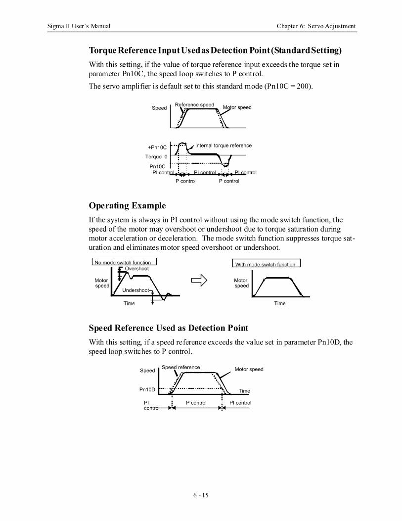
Sigma II User’s Manual Chapter 6: Servo Adjustment
6 - 15
Torque Reference Input Used as Detection Point (Standard Setting) With this setting, if the value of torque reference input exceeds the torque set in parameter Pn10C, the speed loop switches to P control.The servo amplifier is default set to this standard mode (Pn10C = 200).
Operating Example If the system is always in PI control without using the mode switch function, the speed of the motor may overshoot or undershoot due to torque saturation during motor acceleration or deceleration. The mode switch function suppresses torque sat-uration and eliminates motor speed overshoot or undershoot.
Speed Reference Used as Detection Point With this setting, if a speed reference exceeds the value set in parameter Pn10D, the speed loop switches to P control.
Motor speedReference speedSpeed
Internal torque reference+Pn10C
Torque 0
-Pn10CPI control PI control PI control
P control P control
Overshoot
Undershoot
Motor speed
Time
No mode switch function With mode switch function
Motor speed
Time
Speed referenceSpeed
Pn10D
Motor speed
Time
P controlPI control
PI control
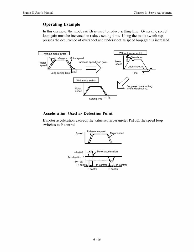
Sigma II User’s Manual Chapter 6: Servo Adjustment
6 - 16
Operating ExampleIn this example, the mode switch is used to reduce setting time. Generally, speed loop gain must be increased to reduce setting time. Using the mode switch sup-presses the occurrence of overshoot and undershoot as speed loop gain is increased.
Acceleration Used as Detection Point If motor acceleration exceeds the value set in parameter Pn10E, the speed loop switches to P control.
Motor speedSpeed reference
Without mode switch
Long setting time
Increase speed loop gain.
OvershootWithout mode switch
With mode switch
Setting time
Suppress overshooting and undershooting.
Motor speed
Motor speed
Motor speed
Undershoot
Time
Motor speedReference speedSpeed
Motor acceleration+Pn10E
Acceleration 0
-Pn10EPI control PI control PI control
P control P control
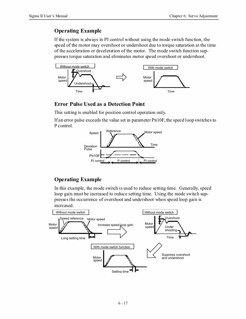
Sigma II User’s Manual Chapter 6: Servo Adjustment
6 - 17
Operating ExampleIf the system is always in PI control without using the mode switch function, the speed of the motor may overshoot or undershoot due to torque saturation at the time of the acceleration or deceleration of the motor. The mode switch function sup-presses torque saturation and eliminates motor speed overshoot or undershoot.
Error Pulse Used as a Detection Point This setting is enabled for position control operation only.If an error pulse exceeds the value set in parameter Pn10F, the speed loop switches to P control.
Operating ExampleIn this example, the mode switch is used to reduce setting time. Generally, speed loop gain must be increased to reduce setting time. Using the mode switch sup-presses the occurrence of overshoot and undershoot when speed loop gain is increased.
Overshoot
Undershoot
Motor speed
Time
Without mode switch With mode switch
Motor speed
Time
Motor speedReferenceSpeed
Pn10F
DeviationPulse
Time
P controlPI control PI control
Motor speedSpeed reference
Without mode switch
Long setting time
Increase speed loop gain.
Overshoot
Without mode switch
With mode switch function
Setting time
Motor speed
Motor speed
Motor speed Under
shooting
Time
Suppress overshoot and undershoot
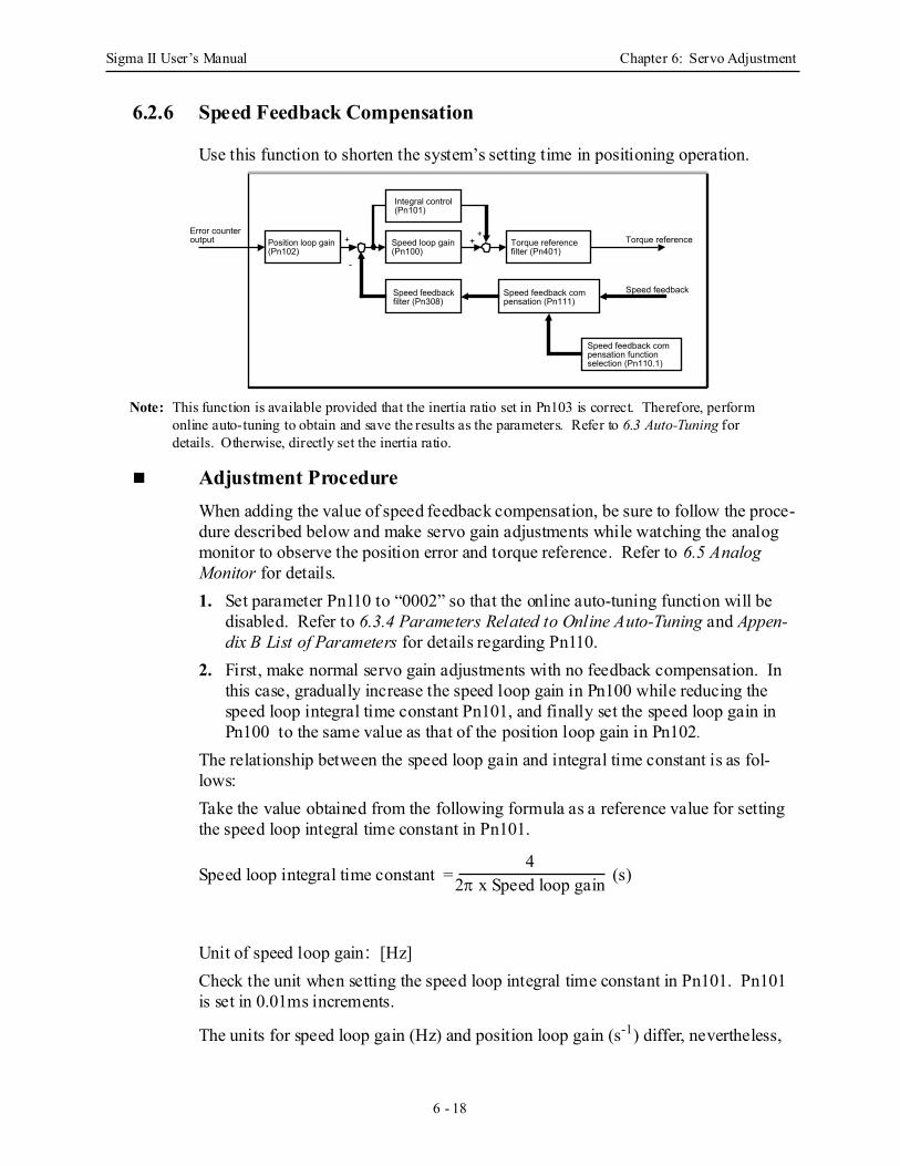
Sigma II User’s Manual Chapter 6: Servo Adjustment
6 - 18
6.2.6 Speed Feedback Compensation
Use this function to shorten the system’s setting time in positioning operation.
Note: This function is available provided that the inertia ratio set in Pn103 is correct. Therefore, perform online auto-tuning to obtain and save the results as the parameters. Refer to 6.3 Auto-Tuning for details. Otherwise, directly set the inertia ratio.
Adjustment Procedure When adding the value of speed feedback compensation, be sure to follow the proce-dure described below and make servo gain adjustments while watching the analog monitor to observe the position error and torque reference. Refer to 6.5 Analog Monitor for details. 1. Set parameter Pn110 to “0002” so that the online auto-tuning function will be
disabled. Refer to 6.3.4 Parameters Related to Online Auto-Tuning and Appen-dix B List of Parameters for details regarding Pn110.
2. First, make normal servo gain adjustments with no feedback compensation. In this case, gradually increase the speed loop gain in Pn100 while reducing the speed loop integral time constant Pn101, and finally set the speed loop gain in Pn100 to the same value as that of the position loop gain in Pn102.
The relationship between the speed loop gain and integral time constant is as fol-lows:Take the value obtained from the following formula as a reference value for setting the speed loop integral time constant in Pn101.
Unit of speed loop gain: [Hz]Check the unit when setting the speed loop integral time constant in Pn101. Pn101 is set in 0.01ms increments.
The units for speed loop gain (Hz) and position loop gain (s-1) differ, nevertheless,
Error counter output Position loop gain
(Pn102)
Integral control (Pn101)
Speed loop gain (Pn100)
Speed feedback filter (Pn308)
Torque reference filter (Pn401)
Torque reference
Speed feedbackSpeed feedback compensation (Pn111)
Speed feedback compensation function selection (Pn110.1)
+
-
++
Speed loop integral time constant = (s)4
2π x Speed loop gain
Sigma II User’s Manual Chapter 6: Servo Adjustment
6 - 19
set these gains to the same numerical value. 3. Repeat step 2 to increase the speed loop gain while watching the position error of
the analog monitor to observe the setting time and the torque reference of the analog monitor to observe any occurrence of vibration. If there is any oscillating noise or noticeable vibration, gradually increase the time constant of the torque reference filter in Pn401.
4. Gradually increase only the position loop gain. When it has been increased about as far as possible, then decrease the speed feedback compensation in Pn111 from 100% to 90%. Then repeat steps 2 and 3.
5. Decrease the speed feedback compensation to a value lower than 90%. Then repeat steps 2 through 4 to shorten the setting time. If the speed feedback com-pensation is too low, however, the response waveform will vibrate.
6. Find the condition in which the shortest setting time is obtainable within the range where the position error or torque reference waveform observed through the analog monitor is not vibrating or unstable.
7. The servo gain adjustment is completed when no further shortening of the posi-tioning time is possible.
• Speed feedback compensation usually makes it possible to increase the speed loop gain and position loop gain. The machinery may vibrate excessively if the compensation value greatly changes or Pn110.1 is set to “1” (i.e., speed feedback compensation disabled) after increasing the speed loop gain or position loop gain.
IMPORTANT
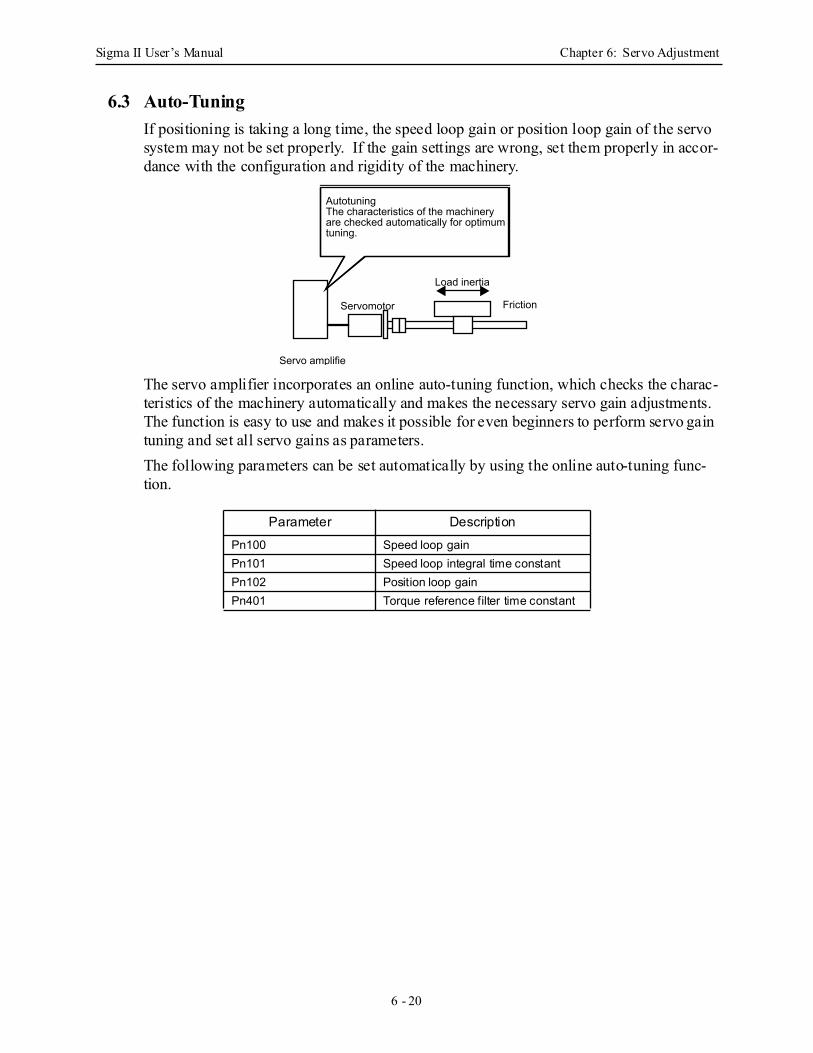
Sigma II User’s Manual Chapter 6: Servo Adjustment
6 - 20
6.3 Auto-TuningIf positioning is taking a long time, the speed loop gain or position loop gain of the servo system may not be set properly. If the gain settings are wrong, set them properly in accor-dance with the configuration and rigidity of the machinery.
The servo amplifier incorporates an online auto-tuning function, which checks the charac-teristics of the machinery automatically and makes the necessary servo gain adjustments. The function is easy to use and makes it possible for even beginners to perform servo gain tuning and set all servo gains as parameters. The following parameters can be set automatically by using the online auto-tuning func-tion.
Parameter DescriptionPn100 Speed loop gainPn101 Speed loop integral time constantPn102 Position loop gainPn401 Torque reference filter time constant
Load inertia
Servomotor
Servo amplifie
Friction
AutotuningThe characteristics of the machinery are checked automatically for optimum tuning.
Sigma II User’s Manual Chapter 6: Servo Adjustment
6 - 21
6.3.1 Online Auto-Tuning
Online auto-tuning is a control function which enables the servo amplifier to check changes in the load inertia during operation in order to maintain the target value for speed loop gain or position loop gain.Online auto-tuning may not work well in the following cases.• When the cycle for load inertia change is 200ms or shorter (when the load
changes rapidly).• When the application has slow acceleration or deceleration using the soft start
function, and the speed error of the servomotor being driven is small.• When adjusting the servomotor manually and operating at low gain (a machine
rigidity of 1 or less).Disable the online auto-tuning function if tuning is not possible. (See 6.4.3 Making Manual Adjustments).
• Do not use online auto-tuning in the following cases:
• When using Torque Control Mode. • When using IP control (only when using parameter Pn10B.1 = 1) for the speed loop. • When using the torque feed–forward function. • When switching gain using /G–SEL.
IMPORTANT
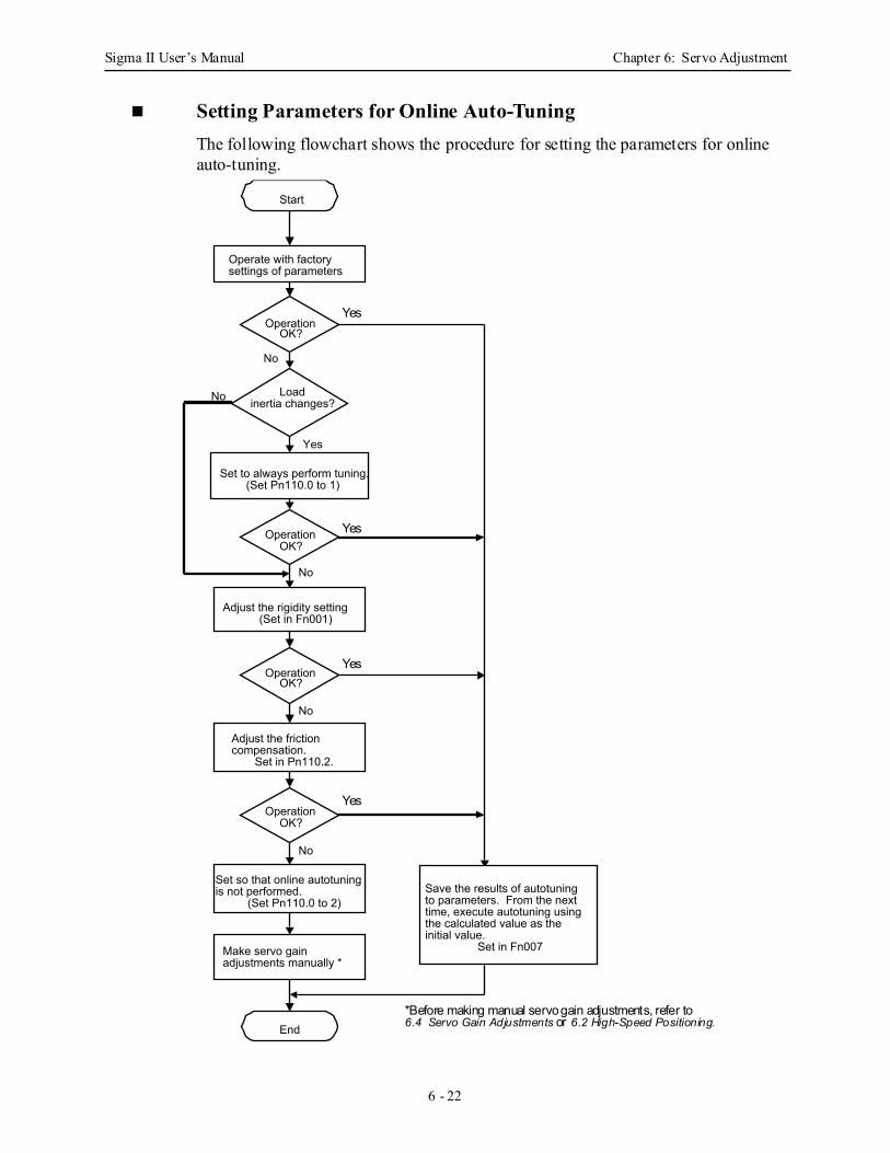
Sigma II User’s Manual Chapter 6: Servo Adjustment
6 - 22
Setting Parameters for Online Auto-Tuning The following flowchart shows the procedure for setting the parameters for online auto-tuning.
Start
Operate with factory settings of parameters
Set to always perform tuning.(Set Pn110.0 to 1)
Adjust the rigidity setting(Set in Fn001)
Set so that online autotuning is not performed.
(Set Pn110.0 to 2)
Loadinertia changes?
Operation OK?
Adjust the friction compensation.
Set in Pn110.2.
End
Make servo gain adjustments manually *
No
Yes
No
No
No
No
Save the results of autotuning to parameters. From the next time, execute autotuning using the calculated value as the initial value.
Set in Fn007
Operation OK?
Operation OK?
Operation OK?
Yes
Yes
Yes
*Before making manual servo gain adjustments, refer to6.4 Servo Gain Adjustments or 6.2 High-Speed Positioning.
Yes
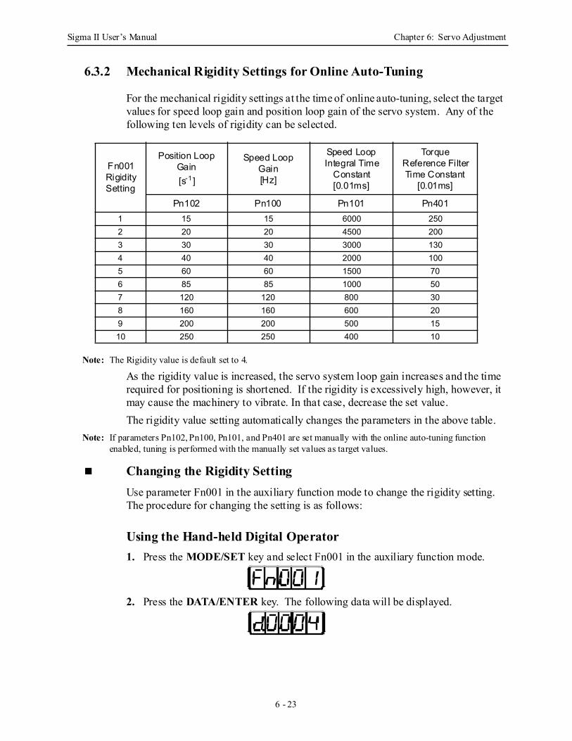
Sigma II User’s Manual Chapter 6: Servo Adjustment
6 - 23
6.3.2 Mechanical Rigidity Settings for Online Auto-Tuning
For the mechanical rigidity settings at the time of online auto-tuning, select the target values for speed loop gain and position loop gain of the servo system. Any of the following ten levels of rigidity can be selected.
Note: The Rigidity value is default set to 4.
As the rigidity value is increased, the servo system loop gain increases and the time required for positioning is shortened. If the rigidity is excessively high, however, it may cause the machinery to vibrate. In that case, decrease the set value.The rigidity value setting automatically changes the parameters in the above table.
Note: If parameters Pn102, Pn100, Pn101, and Pn401 are set manually with the online auto-tuning function enabled, tuning is performed with the manually set values as target values.
Changing the Rigidity Setting Use parameter Fn001 in the auxiliary function mode to change the rigidity setting.The procedure for changing the setting is as follows:
Using the Hand-held Digital Operator 1. Press the MODE/SET key and select Fn001 in the auxiliary function mode.
2. Press the DATA/ENTER key. The following data will be displayed.
Fn001Rigidity Setting
Position Loop Gain[s-1 ]
Speed Loop Gain[Hz]
Speed Loop Integral Time
Constant [0.01ms]
Torque Reference Filter Time Constant
[0.01ms]
Pn102 Pn100 Pn101 Pn4011 15 15 6000 2502 20 20 4500 2003 30 30 3000 1304 40 40 2000 1005 60 60 1500 706 85 85 1000 507 120 120 800 308 160 160 600 209 200 200 500 1510 250 250 400 10
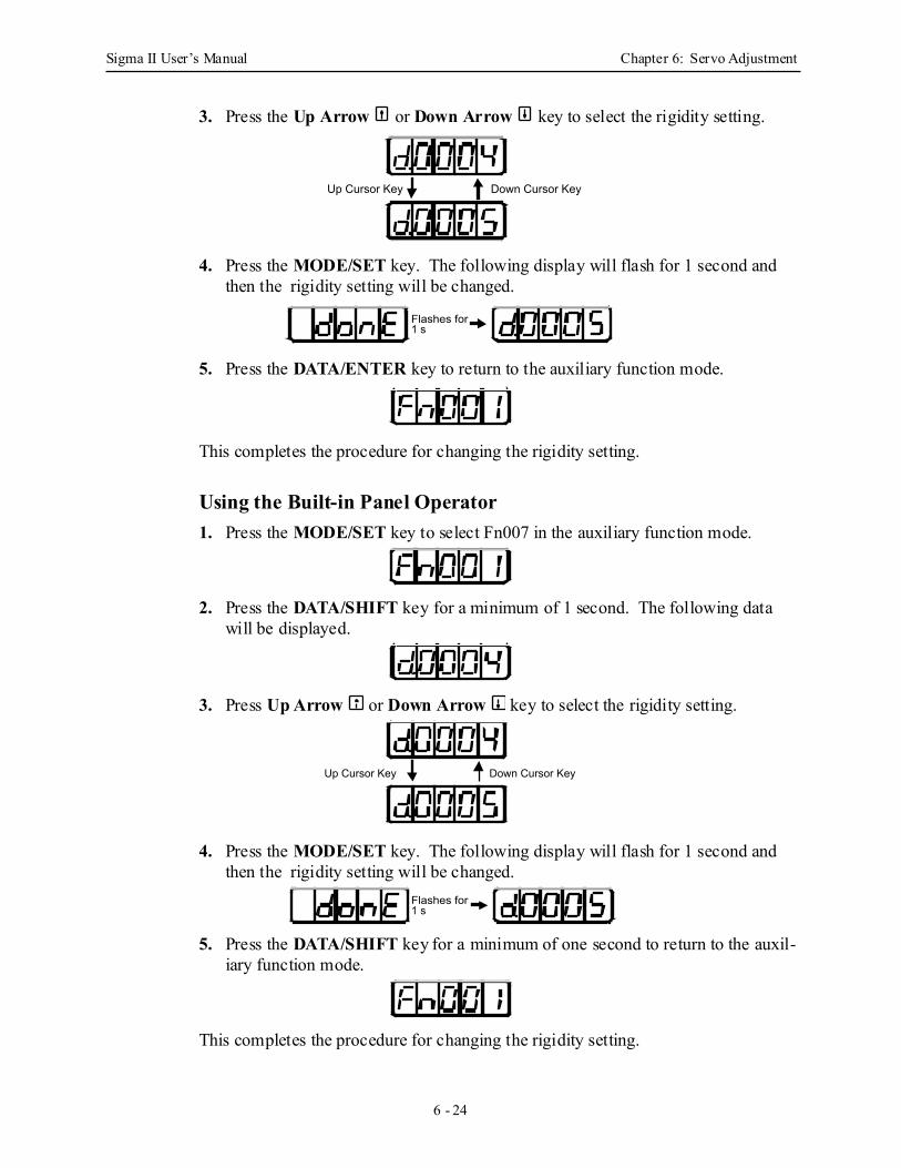
Sigma II User’s Manual Chapter 6: Servo Adjustment
6 - 24
3. Press the Up Arrow or Down Arrow key to select the rigidity setting.
4. Press the MODE/SET key. The following display will flash for 1 second and then the rigidity setting will be changed.
5. Press the DATA/ENTER key to return to the auxiliary function mode.
This completes the procedure for changing the rigidity setting.
Using the Built-in Panel Operator 1. Press the MODE/SET key to select Fn007 in the auxiliary function mode.
2. Press the DATA/SHIFT key for a minimum of 1 second. The following data will be displayed.
3. Press Up Arrow or Down Arrow key to select the rigidity setting.
4. Press the MODE/SET key. The following display will flash for 1 second and then the rigidity setting will be changed.
5. Press the DATA/SHIFT key for a minimum of one second to return to the auxil-iary function mode.
This completes the procedure for changing the rigidity setting.
Up Cursor Key Down Cursor Key
Flashes for 1 s
Up Cursor Key Down Cursor Key
Flashes for 1 s
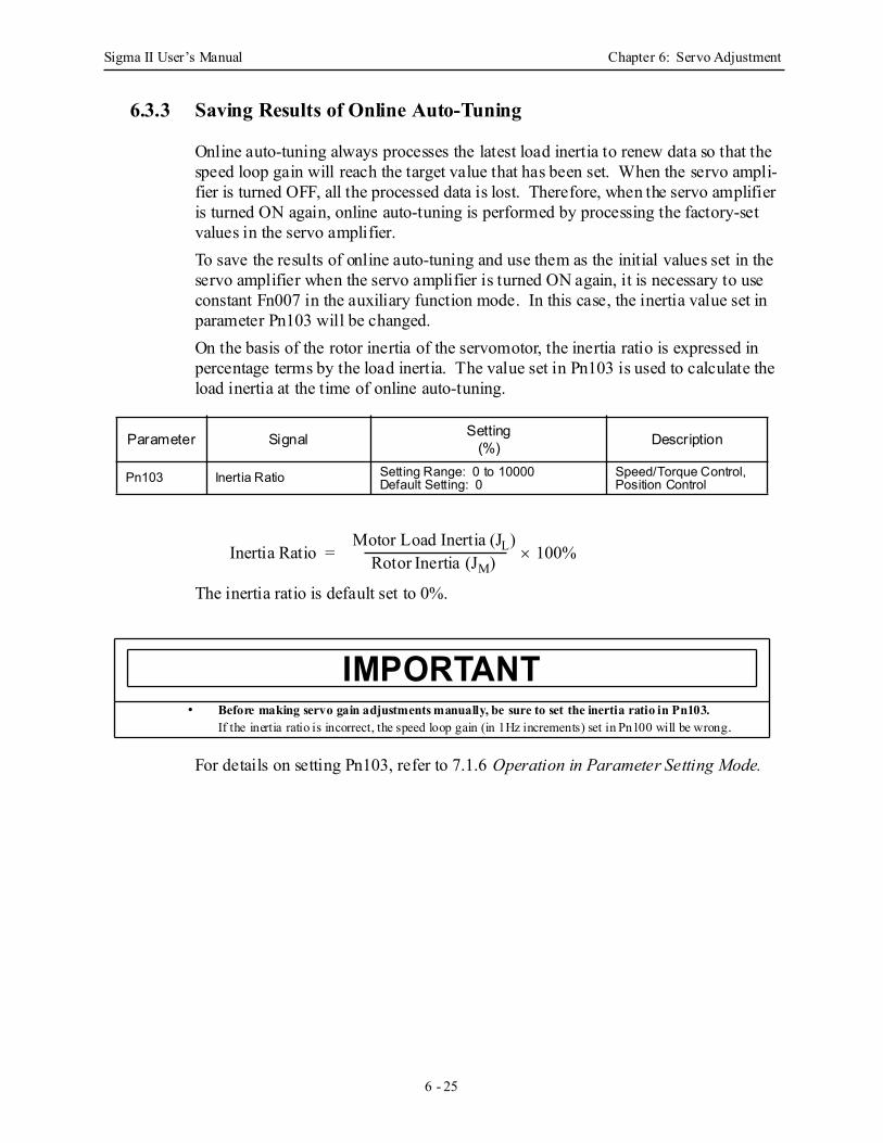
Sigma II User’s Manual Chapter 6: Servo Adjustment
6 - 25
6.3.3 Saving Results of Online Auto-Tuning
Online auto-tuning always processes the latest load inertia to renew data so that the speed loop gain will reach the target value that has been set. When the servo ampli-fier is turned OFF, all the processed data is lost. Therefore, when the servo amplifier is turned ON again, online auto-tuning is performed by processing the factory-set values in the servo amplifier.To save the results of online auto-tuning and use them as the initial values set in the servo amplifier when the servo amplifier is turned ON again, it is necessary to use constant Fn007 in the auxiliary function mode. In this case, the inertia value set in parameter Pn103 will be changed.On the basis of the rotor inertia of the servomotor, the inertia ratio is expressed in percentage terms by the load inertia. The value set in Pn103 is used to calculate the load inertia at the time of online auto-tuning.
The inertia ratio is default set to 0%.
For details on setting Pn103, refer to 7.1.6 Operation in Parameter Setting Mode.
Parameter Signal Setting(%) Description
Pn103 Inertia Ratio Setting Range: 0 to 10000Default Setting: 0
Speed/Torque Control, Position Control
• Before making servo gain adjustments manually, be sure to set the inertia ratio in Pn103.If the inertia ratio is incorrect, the speed loop gain (in 1Hz increments) set in Pn100 will be wrong.
Inertia Ratio = × 100%Motor Load Inertia (JL)
Rotor Inertia (JM)
IMPORTANT
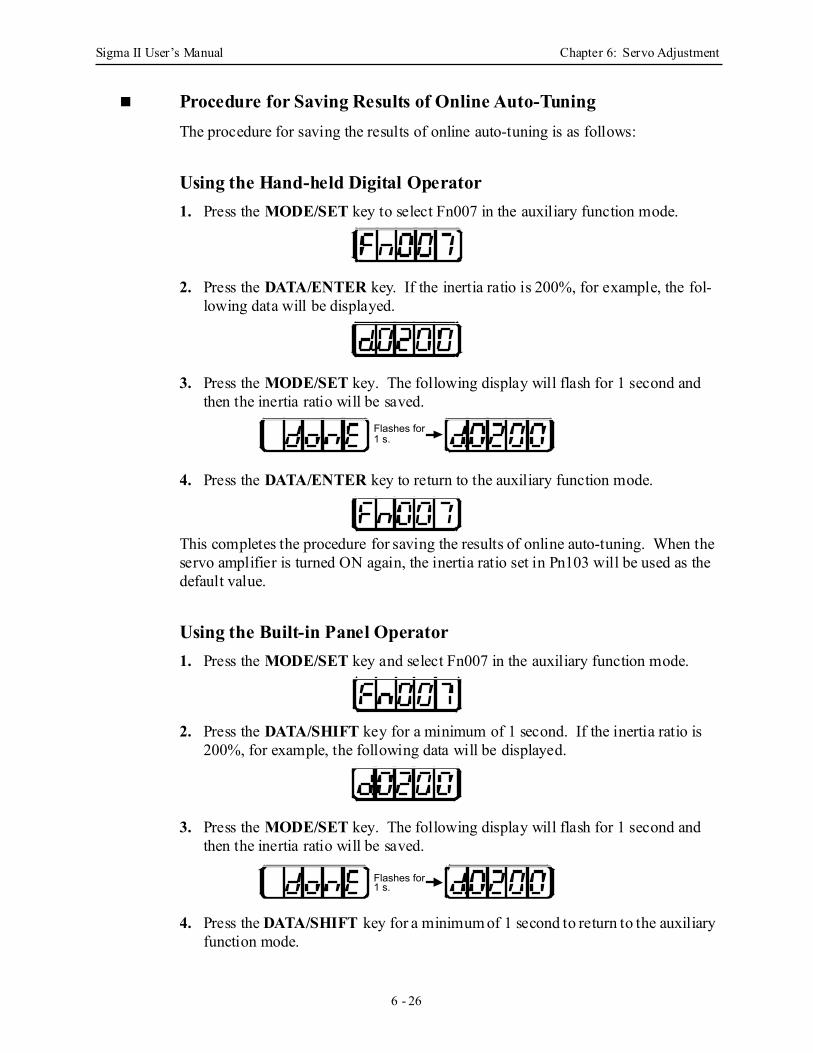
Sigma II User’s Manual Chapter 6: Servo Adjustment
6 - 26
Procedure for Saving Results of Online Auto-TuningThe procedure for saving the results of online auto-tuning is as follows:
Using the Hand-held Digital Operator 1. Press the MODE/SET key to select Fn007 in the auxiliary function mode.
2. Press the DATA/ENTER key. If the inertia ratio is 200%, for example, the fol-lowing data will be displayed.
3. Press the MODE/SET key. The following display will flash for 1 second and then the inertia ratio will be saved.
4. Press the DATA/ENTER key to return to the auxiliary function mode.
This completes the procedure for saving the results of online auto-tuning. When the servo amplifier is turned ON again, the inertia ratio set in Pn103 will be used as the default value.
Using the Built-in Panel Operator 1. Press the MODE/SET key and select Fn007 in the auxiliary function mode.
2. Press the DATA/SHIFT key for a minimum of 1 second. If the inertia ratio is 200%, for example, the following data will be displayed.
3. Press the MODE/SET key. The following display will flash for 1 second and then the inertia ratio will be saved.
4. Press the DATA/SHIFT key for a minimum of 1 second to return to the auxiliary function mode.
Flashes for 1 s.
Flashes for 1 s.

Sigma II User’s Manual Chapter 6: Servo Adjustment
6 - 27
This completes the procedure for saving the results of online auto-tuning. When the servo amplifier is turned ON again, the inertia ratio set in Pn103 will be used as the default value.
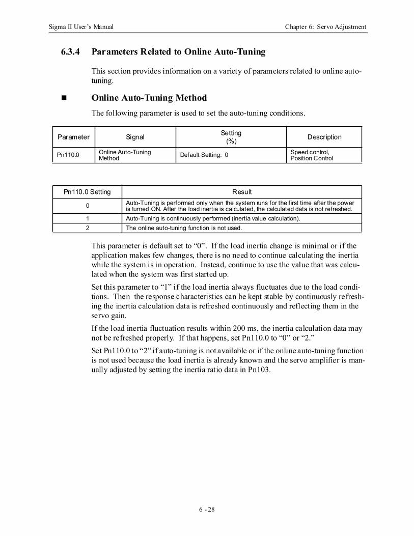
Sigma II User’s Manual Chapter 6: Servo Adjustment
6 - 28
6.3.4 Parameters Related to Online Auto-Tuning
This section provides information on a variety of parameters related to online auto-tuning.
Online Auto-Tuning Method The following parameter is used to set the auto-tuning conditions.
This parameter is default set to “0”. If the load inertia change is minimal or if the application makes few changes, there is no need to continue calculating the inertia while the system is in operation. Instead, continue to use the value that was calcu-lated when the system was first started up.Set this parameter to “1” if the load inertia always fluctuates due to the load condi-tions. Then the response characteristics can be kept stable by continuously refresh-ing the inertia calculation data is refreshed continuously and reflecting them in the servo gain.If the load inertia fluctuation results within 200 ms, the inertia calculation data may not be refreshed properly. If that happens, set Pn110.0 to “0” or “2.”Set Pn110.0 to “2” if auto-tuning is not available or if the online auto-tuning function is not used because the load inertia is already known and the servo amplifier is man-ually adjusted by setting the inertia ratio data in Pn103.
Parameter Signal Setting(%) Description
Pn110.0 Online Auto-Tuning Method Default Setting: 0 Speed control,
Position Control
Pn110.0 Setting Result
0 Auto-Tuning is performed only when the system runs for the first time after the power is turned ON. After the load inertia is calculated, the calculated data is not refreshed.
1 Auto-Tuning is continuously performed (inertia value calculation).2 The online auto-tuning function is not used.
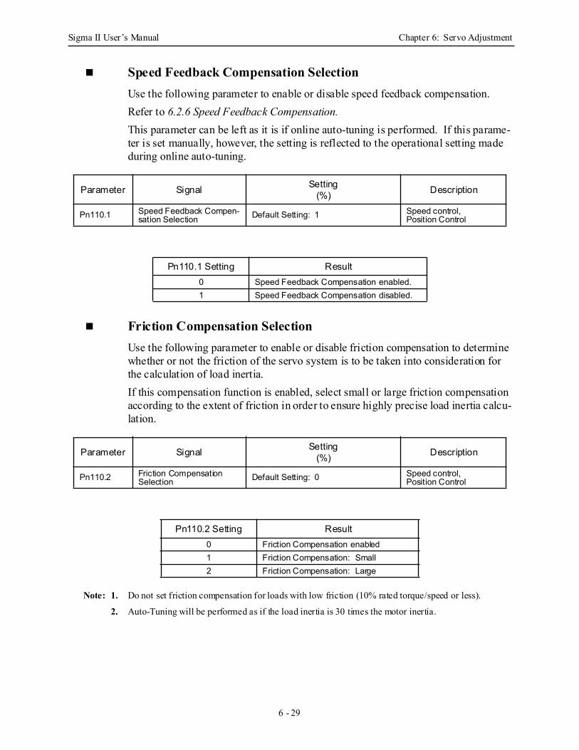
Sigma II User’s Manual Chapter 6: Servo Adjustment
6 - 29
Speed Feedback Compensation SelectionUse the following parameter to enable or disable speed feedback compensation.Refer to 6.2.6 Speed Feedback Compensation.This parameter can be left as it is if online auto-tuning is performed. If this parame-ter is set manually, however, the setting is reflected to the operational setting made during online auto-tuning.
Friction Compensation Selection Use the following parameter to enable or disable friction compensation to determine whether or not the friction of the servo system is to be taken into consideration for the calculation of load inertia.If this compensation function is enabled, select small or large friction compensation according to the extent of friction in order to ensure highly precise load inertia calcu-lation.
Note: 1. Do not set friction compensation for loads with low friction (10% rated torque/speed or less).
2. Auto-Tuning will be performed as if the load inertia is 30 times the motor inertia.
Parameter Signal Setting(%) Description
Pn110.1 Speed Feedback Compen-sation Selection Default Setting: 1 Speed control,
Position Control
Pn110.1 Setting Result0 Speed Feedback Compensation enabled.1 Speed Feedback Compensation disabled.
Parameter Signal Setting(%) Description
Pn110.2 Friction Compensation Selection Default Setting: 0 Speed control,
Position Control
Pn110.2 Setting Result0 Friction Compensation enabled1 Friction Compensation: Small2 Friction Compensation: Large
Sigma II User’s Manual Chapter 6: Servo Adjustment
6 - 30
6.4 Servo Gain AdjustmentsThis section describes information on the basic rules of gain adjustments in the servo amplifier, adjustment methods in a variety of cases, and reference set values.
6.4.1 Servo Gain Parameters
The following parameters must be set properly for servo gain adjustments.• Pn100: Speed loop gain • Pn101: Speed loop integral time constant • Pn102: Position loop gain • Pn401: Torque reference filter time constant If the servo amplifier is used in the speed control mode with the analog voltage refer-ence, the position loop is controlled by the host device. Therefore, position loop gain is adjusted through the host device. If the host is not available for adjustments of position loop gain, set the speed refer-ence input gain in parameter Pn300. If the set value is improper, the servomotor may not run at top speed.
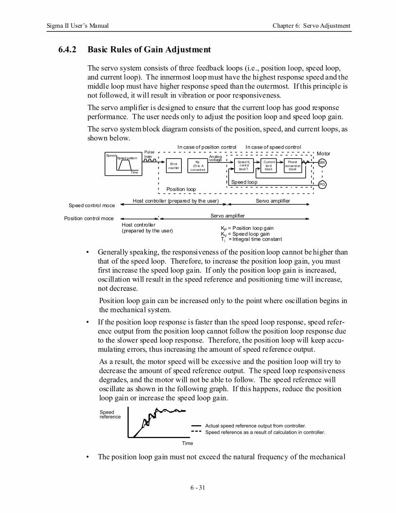
Sigma II User’s Manual Chapter 6: Servo Adjustment
6 - 31
6.4.2 Basic Rules of Gain Adjustment
The servo system consists of three feedback loops (i.e., position loop, speed loop, and current loop). The innermost loop must have the highest response speed and the middle loop must have higher response speed than the outermost. If this principle is not followed, it will result in vibration or poor responsiveness. The servo amplifier is designed to ensure that the current loop has good response performance. The user needs only to adjust the position loop and speed loop gain. The servo system block diagram consists of the position, speed, and current loops, as shown below.
• Generally speaking, the responsiveness of the position loop cannot be higher than that of the speed loop. Therefore, to increase the position loop gain, you must first increase the speed loop gain. If only the position loop gain is increased, oscillation will result in the speed reference and positioning time will increase, not decrease. Position loop gain can be increased only to the point where oscillation begins in the mechanical system.
• If the position loop response is faster than the speed loop response, speed refer-ence output from the position loop cannot follow the position loop response due to the slower speed loop response. Therefore, the position loop will keep accu-mulating errors, thus increasing the amount of speed reference output. As a result, the motor speed will be excessive and the position loop will try to decrease the amount of speed reference output. The speed loop responsiveness degrades, and the motor will not be able to follow. The speed reference will oscillate as shown in the following graph. If this happens, reduce the position loop gain or increase the speed loop gain.
• The position loop gain must not exceed the natural frequency of the mechanical
Speed KVc ontrolblock Ti
KP = Position loop gainKV = Speed loop gainTi = Integral time constant
SpeedSpeed pattern
Time
Error Current
counter
Kp(D to A lim it
block
Powerconversi on
blockconverter)
Analogvoltage
Pulsetrain
In case of position control In case of speed control
Position loopSpeed loop
Host controller (prepared by the user) Servo amplifier
Host controller
Servo amplifier
(prepared by the user)
Position control moce
Speed control moce
MotorSM
PG
Speed reference
Time
Actual speed reference output from controller.Speed reference as a result of calculation in controller.
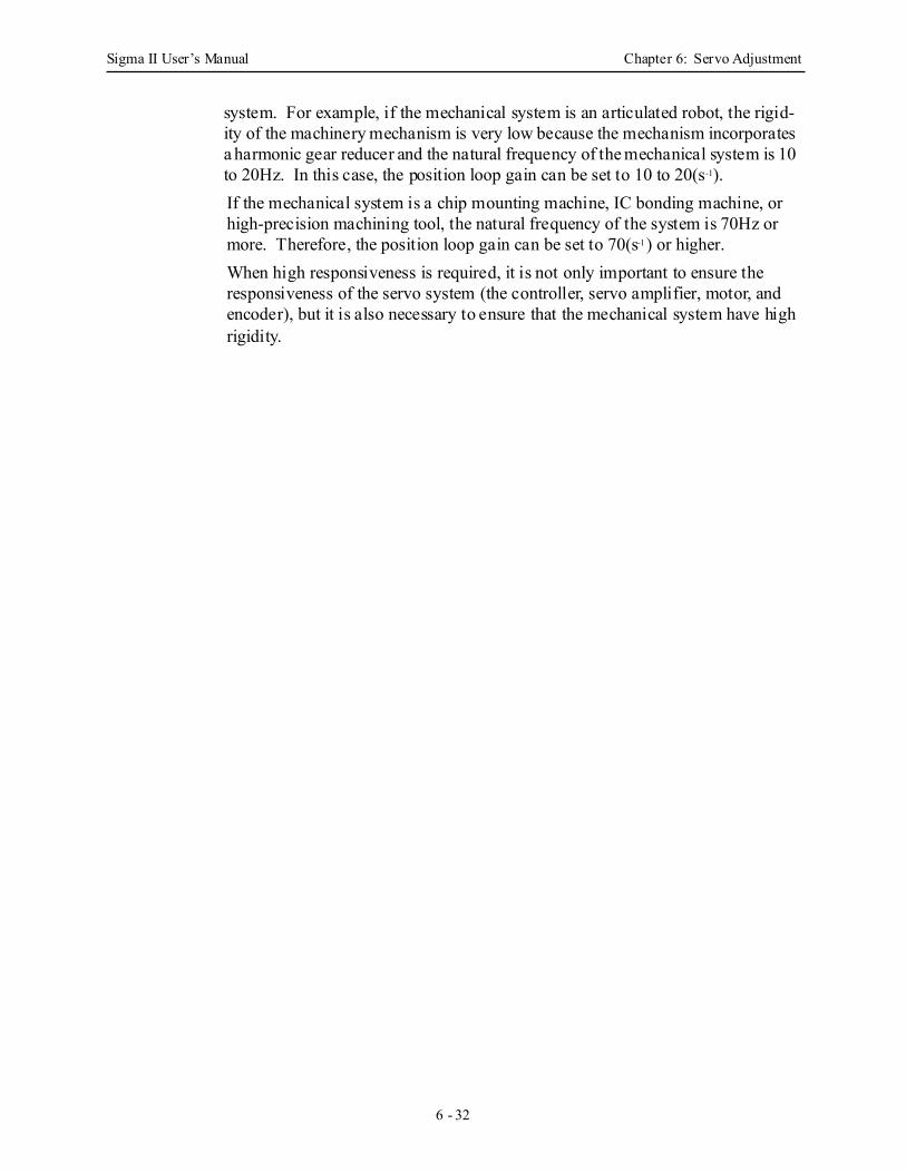
Sigma II User’s Manual Chapter 6: Servo Adjustment
6 - 32
system. For example, if the mechanical system is an articulated robot, the rigid-ity of the machinery mechanism is very low because the mechanism incorporates a harmonic gear reducer and the natural frequency of the mechanical system is 10 to 20Hz. In this case, the position loop gain can be set to 10 to 20(s-1).If the mechanical system is a chip mounting machine, IC bonding machine, or high-precision machining tool, the natural frequency of the system is 70Hz or more. Therefore, the position loop gain can be set to 70(s-1) or higher.When high responsiveness is required, it is not only important to ensure the responsiveness of the servo system (the controller, servo amplifier, motor, and encoder), but it is also necessary to ensure that the mechanical system have high rigidity.
Sigma II User’s Manual Chapter 6: Servo Adjustment
6 - 33
6.4.3 Making Manual Adjustments
The auto-tuning function uses a gain adjustment algorithm with a comparatively large safety margin by considering a variety of mechanical systems to which the servo amplifier is applied. Therefore, the servo amplifier may not satisfy the response characteristics of some applications. The auto-tuning function is not avail-able to machines with low rigidity or high fluctuation.In such cases, observe the mechanical systems and make manual adjustments of parameters.
Speed Control
Required ParametersThe following parameters are used.• Speed Loop Gain (Pn100)
This parameter is used for determining the responsiveness of the speed loop. For the best response, set this parameter as high as possible, without exceeding the point where the mechanical system vibrates. The value of speed loop gain is the same as the set value of Pn100 if the inertia ratio set in Pn103 is correct.Speed loop gain Kv = Set value of Pn100 (Hz)Set Pn103 to the following value.
Note: In the case of manual adjustments of parameters, the user must set the value of parameter Pn103. The inertia ratio can be obtained if the servo gain constant is written with parameter Fn007 after auto-tun-ing has been performed. For details regarding Fn007, refer to 6.3 Auto-Tuning.
• Speed Loop Integral Time Constant (Pn101) The speed loop has an integral element so that the speed loop can respond to minute inputs. This integral element delays the operation of the servo system, resulting in a longer positioning settling time. As the value of the time constant increases, the response becomes slower. If the load inertia is large or the mechanical system is likely to vibrate, make sure that the speed loop integral time constant is large enough. Use the following formula to calculate the opti-mum integral time constant.
Where: Ti = Integral time constant [s]Kv = Speed loop gain (calculated from the above) [Hz]
Pn103 Setting Value = × 100%Motor load inertia (JL)
Servomotor rotor inertia (JM)
Ti ≥ 2.3 × 1
2π × Kv
Sigma II User’s Manual Chapter 6: Servo Adjustment
6 - 34
• Torque Reference Filter Time Constant (Pn401) If the mechanical system uses ball screws, torsional resonance may result. In this case, the oscillation noise will be a high-pitched tone. The oscillation may be minimized by increasing the time constant of the torque reference filter. Like the integral time constant, this filter causes a delay in the operation of the servo system. Therefore, this constant must not be set to an excessively large value.
• Speed Reference Input Gain (Pn300)
Changing the speed reference input gain set in Pn300 is equivalent to changing the position loop gain. In other words, an increase in the speed reference input gain set in Pn300 is equivalent to a decrease in the position loop gain and vice versa. Use this parameter in the following cases.• When the host controller does not have a function for adjusting the position
loop gain. (The host incorporates a D/A converter to change the number of bits but cannot make fine adjustments of position loop gain.)
• When it is necessary to clamp the full range of the speed reference output of the host device to a specified rotation speed.
In normal operation, the default setting can be used as is.Note: If the servo amplifier is used for speed control, the position loop gain set in Pn102 is enabled in zero–
clamp mode only. In normal control operation, change the position loop gain through the host or change the speed reference input gain in Pn300 in the servo amplifier. The position loop gain remains the same if the setting in Pn102 is changed.
Adjustment Method1. Set the position loop gain to a low value in the host controller. Then increase the
speed loop gain set in Pn100 to within a range where there is no noise or oscilla-tion. If the position loop gain cannot be changed through the host controller, increase the speed reference input gain set in Pn300 to a larger value.
2. Decrease the speed loop gain a little from the value set in step 1. Then increase the position loop gain through the host controller to a range where there is no noise or oscillation. Decrease the set value of Pn300 even if the position loop gain cannot be changed through the host controller.
3. Set the speed loop integral time constant in Pn101 while observing the position-ing settling time and the vibration of the mechanical system. If the constant is too large, positioning settling time will be long.
4. Set the torque reference filter to a small value in Pn401 if the mechanical system has no apparent shaft torsional resonance. If the mechanical system generates oscillation noise in a high-pitched tone, shaft torsional resonance may be occur-ring. In that case, set Pn401 to a larger value.
5. Finally, progressively make fine adjustments to parameters such as the position loop gain, speed loop gain, and integral time constant to find the optimal point.
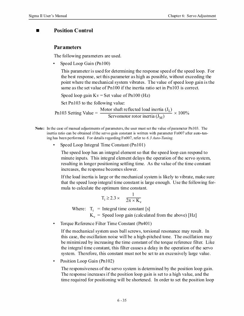
Sigma II User’s Manual Chapter 6: Servo Adjustment
6 - 35
Position Control
ParametersThe following parameters are used.• Speed Loop Gain (Pn100)
This parameter is used for determining the response speed of the speed loop. For the best response, set this parameter as high as possible, without exceeding the point where the mechanical system vibrates. The value of speed loop gain is the same as the set value of Pn100 if the inertia ratio set in Pn103 is correct.Speed loop gain Kv = Set value of Pn100 (Hz)Set Pn103 to the following value:
Note: In the case of manual adjustments of parameters, the user must set the value of parameter Pn103. The inertia ratio can be obtained if the servo gain constant is written with parameter Fn007 after auto-tun-ing has been performed. For details regarding Fn007, refer to 6.3 Auto-Tuning.
• Speed Loop Integral Time Constant (Pn101) The speed loop has an integral element so that the speed loop can respond to minute inputs. This integral element delays the operation of the servo system, resulting in longer positioning settling time. As the value of the time constant increases, the response becomes slower. If the load inertia is large or the mechanical system is likely to vibrate, make sure that the speed loop integral time constant is large enough. Use the following for-mula to calculate the optimum time constant.
Where: Ti = Integral time constant [s]Kv = Speed loop gain (calculated from the above) [Hz]
• Torque Reference Filter Time Constant (Pn401) If the mechanical system uses ball screws, torsional resonance may result. In this case, the oscillation noise will be a high-pitched tone. The oscillation may be minimized by increasing the time constant of the torque reference filter. Like the integral time constant, this filter causes a delay in the operation of the servo system. Therefore, this constant must not be set to an excessively large value.
• Position Loop Gain (Pn102) The responsiveness of the servo system is determined by the position loop gain. The response increases if the position loop gain is set to a high value, and the time required for positioning will be shortened. In order to set the position loop
Pn103 Setting Value = × 100%Motor shaft reflected load inertia (JL)
Servomotor rotor inertia (JM)
Ti ≥ 2.3 × 1
2π × Kv
Sigma II User’s Manual Chapter 6: Servo Adjustment
6 - 36
gain to a high value, the rigidity and natural frequency of the mechanical system must be high.The responsiveness of the whole servo system may become unstable if only the position loop gain is increased. Because the speed reference, as output from the position loop, is likely to become unstable. Increase the speed loop gain while observing the response.
Adjustment Method 1. Set the position loop gain to a comparatively low value. Then increase the speed
loop gain set in Pn100 to within a range where there is no noise or oscillation. 2. Decrease the speed loop gain a little from the value set in step 1. Then increase
the position loop gain to within a range where there is no overshooting or oscilla-tion.
3. Set the speed loop integral time constant in Pn101 while observing the position-ing settling time and the vibration of the mechanical system. If the constant is too large, the positioning settling time will be too long.
4. Set the torque reference filter to a small value in Pn401 if the mechanical system has shaft torsional resonance. If the mechanical system generates oscillation noise in a high-pitched tone, shaft torsional resonance may occur. In that case, set Pn401 to a larger value.
5. Finally, progressively make fine adjustments to parameters such as the position loop gain, speed loop gain, and integral time constant to find the optimal points.
Function to Improve Response CharacteristicsThe mode switch, feed-forward, and bias functions can improve the response of the servo system only if they are used properly. If they are used improperly, they will worsen the response. Refer to the following instructions and make adjustments to these functions while observing the change in the actual response.
Mode Switch Use the mode switch function to improve the transient characteristics of the servo system if there is torque reference saturation at the time of acceleration or decelera-tion. The speed loop in PI (proportional and integral) control is switched over to P (proportional) control when the operation speed exceeds the set value in this func-tion.
Feed-forward Function The responsiveness is increased by using the feed-forward function. This function is not effective if the position loop gain is set to a high value. Adjust the feed-forward set value of Pn109 as described below.
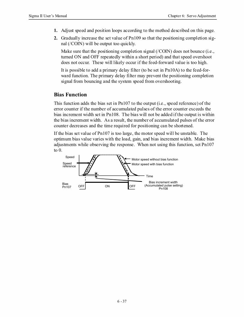
Sigma II User’s Manual Chapter 6: Servo Adjustment
6 - 37
1. Adjust speed and position loops according to the method described on this page.2. Gradually increase the set value of Pn109 so that the positioning completion sig-
nal (/COIN) will be output too quickly.Make sure that the positioning completion signal (/COIN) does not bounce (i.e., turned ON and OFF repeatedly within a short period) and that speed overshoot does not occur. These will likely occur if the feed-forward value is too high.It is possible to add a primary delay filter (to be set in Pn10A) to the feed-for-ward function. The primary delay filter may prevent the positioning completion signal from bouncing and the system speed from overshooting.
Bias Function This function adds the bias set in Pn107 to the output (i.e., speed reference) of the error counter if the number of accumulated pulses of the error counter exceeds the bias increment width set in Pn108. The bias will not be added if the output is within the bias increment width. As a result, the number of accumulated pulses of the error counter decreases and the time required for positioning can be shortened.If the bias set value of Pn107 is too large, the motor speed will be unstable. The optimum bias value varies with the load, gain, and bias increment width. Make bias adjustments while observing the response. When not using this function, set Pn107 to 0.
Speed
Speed reference
Bias Pn107
Motor speed without bias functionMotor speed with bias function
Time
ONOFF OFFBias increment width
(Accumulated pulse setting)Pn108
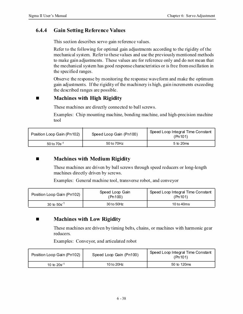
Sigma II User’s Manual Chapter 6: Servo Adjustment
6 - 38
6.4.4 Gain Setting Reference Values
This section describes servo gain reference values.Refer to the following for optimal gain adjustments according to the rigidity of the mechanical system. Refer to these values and use the previously mentioned methods to make gain adjustments. These values are for reference only and do not mean that the mechanical system has good response characteristics or is free from oscillation in the specified ranges.Observe the response by monitoring the response waveform and make the optimum gain adjustments. If the rigidity of the machinery is high, gain increments exceeding the described ranges are possible.
Machines with High Rigidity These machines are directly connected to ball screws.Examples: Chip mounting machine, bonding machine, and high-precision machine tool
Machines with Medium Rigidity These machines are driven by ball screws through speed reducers or long-length machines directly driven by screws.Examples: General machine tool, transverse robot, and conveyor
Machines with Low Rigidity These machines are driven by timing belts, chains, or machines with harmonic gear reducers.Examples: Conveyor, and articulated robot
Position Loop Gain (Pn102) Speed Loop Gain (Pn100) Speed Loop Integral Time Constant (Pn101)
50 to 70s-1 50 to 70Hz 5 to 20ms
Position Loop Gain (Pn102) Speed Loop Gain(Pn100)
Speed Loop Integral Time Constant (Pn101)
30 to 50s-1 30 to 50Hz 10 to 40ms
Position Loop Gain (Pn102) Speed Loop Gain (Pn100) Speed Loop Integral Time Constant (Pn101)
10 to 20s-1 10 to 20Hz 50 to 120ms
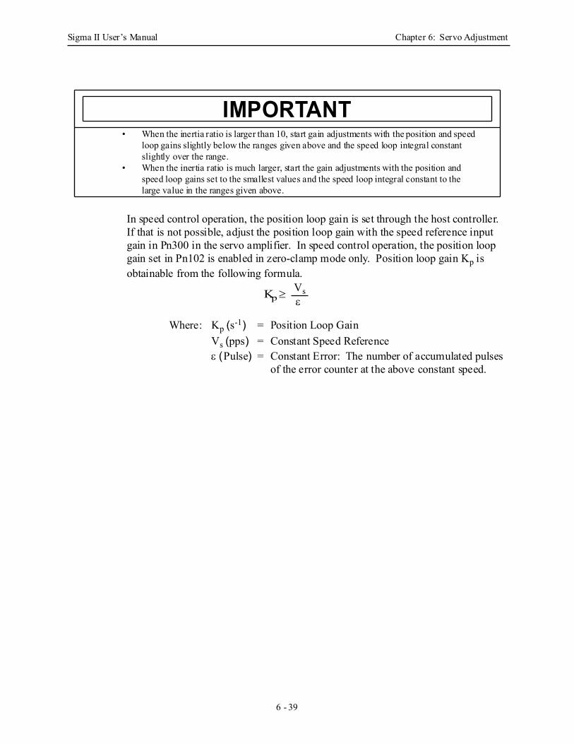
Sigma II User’s Manual Chapter 6: Servo Adjustment
6 - 39
In speed control operation, the position loop gain is set through the host controller. If that is not possible, adjust the position loop gain with the speed reference input gain in Pn300 in the servo amplifier. In speed control operation, the position loop gain set in Pn102 is enabled in zero-clamp mode only. Position loop gain Kp is obtainable from the following formula.
Where: Kp (s-1) = Position Loop Gain Vs (pps) = Constant Speed Reference ε (Pulse) = Constant Error: The number of accumulated pulses
of the error counter at the above constant speed.
• When the inertia ratio is larger than 10, start gain adjustments with the position and speed loop gains slightly below the ranges given above and the speed loop integral constant slightly over the range.
• When the inertia ratio is much larger, start the gain adjustments with the position and speed loop gains set to the smallest values and the speed loop integral constant to the large value in the ranges given above.
IMPORTANT
Kp ≥ Vs ε
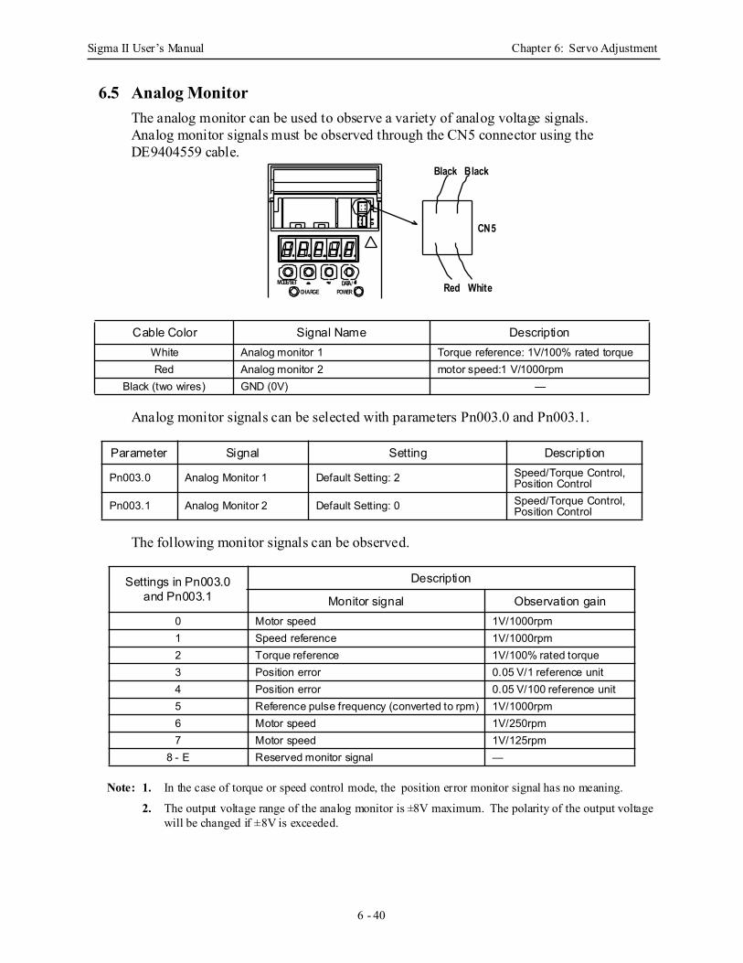
Sigma II User’s Manual Chapter 6: Servo Adjustment
6 - 40
6.5 Analog MonitorThe analog monitor can be used to observe a variety of analog voltage signals.Analog monitor signals must be observed through the CN5 connector using the DE9404559 cable.
Analog monitor signals can be selected with parameters Pn003.0 and Pn003.1.
The following monitor signals can be observed.
Note: 1. In the case of torque or speed control mode, the position error monitor signal has no meaning.
2. The output voltage range of the analog monitor is ±8V maximum. The polarity of the output voltage will be changed if ±8V is exceeded.
Cable Color Signal Name DescriptionWhite Analog monitor 1 Torque reference: 1V/100% rated torqueRed Analog monitor 2 motor speed:1 V/1000rpm
Black (two wires) GND (0V) —
Parameter Signal Setting Description
Pn003.0 Analog Monitor 1 Default Setting: 2 Speed/Torque Control, Position Control
Pn003.1 Analog Monitor 2 Default Setting: 0 Speed/Torque Control, Position Control
Settings in Pn003.0 and Pn003.1
Description
Monitor signal Observation gain0 Motor speed 1V/1000rpm1 Speed reference 1V/1000rpm2 Torque reference 1V/100% rated torque3 Position error 0.05 V/1 reference unit4 Position error 0.05 V/100 reference unit5 Reference pulse frequency (converted to rpm) 1V/1000rpm6 Motor speed 1V/250rpm7 Motor speed 1V/125rpm
8 - E Reserved monitor signal —
MODE/SETCHARGE
DATA/POWER
CN5
Red White
Black Black
Sigma II User’s Manual Chapter 7: Using the Digital Operator
7 - 1
7 Using the Digital OperatorThis chapter describes the basic operation of the digital operator and the features it offers. All parameter settings and motor operations can be executed by simple, convenient operations. Operate the digital operator as you read through this chapter.
7.1 Basic Operation............................................................................................................. 7-2
7.1.1 Connecting the Digital Operator.......................................................................... 7-2
7.1.2 Functions .............................................................................................................. 7-3
7.1.3 Resetting Servo Alarms ....................................................................................... 7-5
7.1.4 Basic Mode Selection .......................................................................................... 7-6
7.1.5 Status Display Mode ............................................................................................ 7-7
7.1.6 Operation in Parameter Setting Mode ............................................................... 7-10
7.1.7 Operation in Monitor Mode ............................................................................... 7-18
7.2 Applied Operation....................................................................................................... 7-24
7.2.1 Operation in Alarm Traceback Mode ................................................................ 7-25
7.2.2 JOG Operation Using the Digital Operator ....................................................... 7-27
7.2.3 Automatic Adjustment of the Speed and Torque Reference Offset ................... 7-30
7.2.4 Manual Adjustment of the Speed and Torque Reference Offset ....................... 7-33
7.2.5 Clearing Alarm Traceback Data ........................................................................ 7-38
7.2.6 Checking the Motor Model ................................................................................ 7-40
7.2.7 Checking the Software Version.......................................................................... 7-43
7.2.8 Origin Search Model.......................................................................................... 7-44
7.2.9 Initializing Parameter Settings ........................................................................... 7-47
7.2.10 Manual Zero Adjustment and Gain Adjustment of Analog Monitor Output .... 7-49
7.2.11 Adjusting the Motor Current Detection Offset .................................................. 7-54
7.2.12 Write Protected Setting ...................................................................................... 7-58
7.2.13 Clearing the Option Unit Detection Alarm ........................................................ 7-60
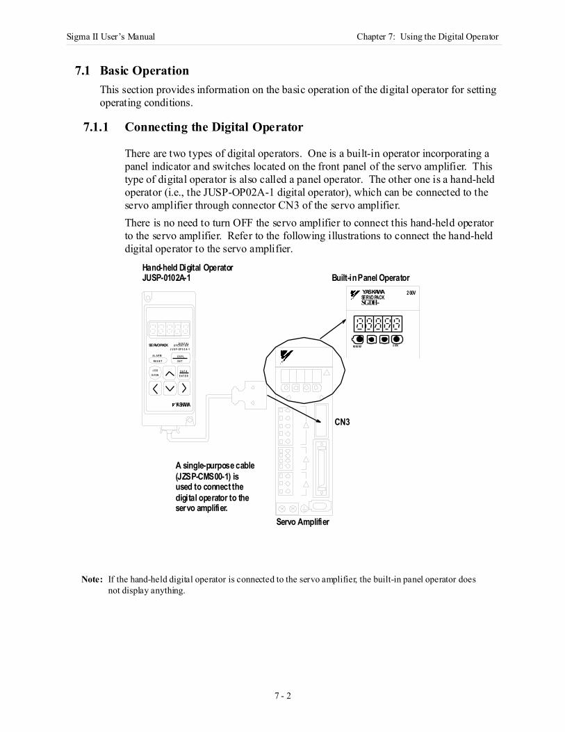
Sigma II User’s Manual Chapter 7: Using the Digital Operator
7 - 2
7.1 Basic OperationThis section provides information on the basic operation of the digital operator for setting operating conditions.
7.1.1 Connecting the Digital Operator
There are two types of digital operators. One is a built-in operator incorporating a panel indicator and switches located on the front panel of the servo amplifier. This type of digital operator is also called a panel operator. The other one is a hand-held operator (i.e., the JUSP-OP02A-1 digital operator), which can be connected to the servo amplifier through connector CN3 of the servo amplifier. There is no need to turn OFF the servo amplifier to connect this hand-held operator to the servo amplifier. Refer to the following illustrations to connect the hand-held digital operator to the servo amplifier.
Note: If the hand-held digital operator is connected to the servo amplifier, the built-in panel operator does not display anything.
YASKAWA 2 00V
MO DE/ SET D ATA/SERVOPACK
A L A R M
R E S E T
D I G I T A LO P E R A T O RJ U S P - O P 0 2 A - 1
D S P LS E T
D A T AE N T E R
J O GS V O N
YASKAWA
Hand-held Digital Operator JUSP-0102A-1 Built-in Panel Operator
CN3
Servo Amplifier
A single-purpose cable(JZSP-CMS00-1) isused to connect the
SGDH-SERVO PACK
servo amplifier.digital operator to the
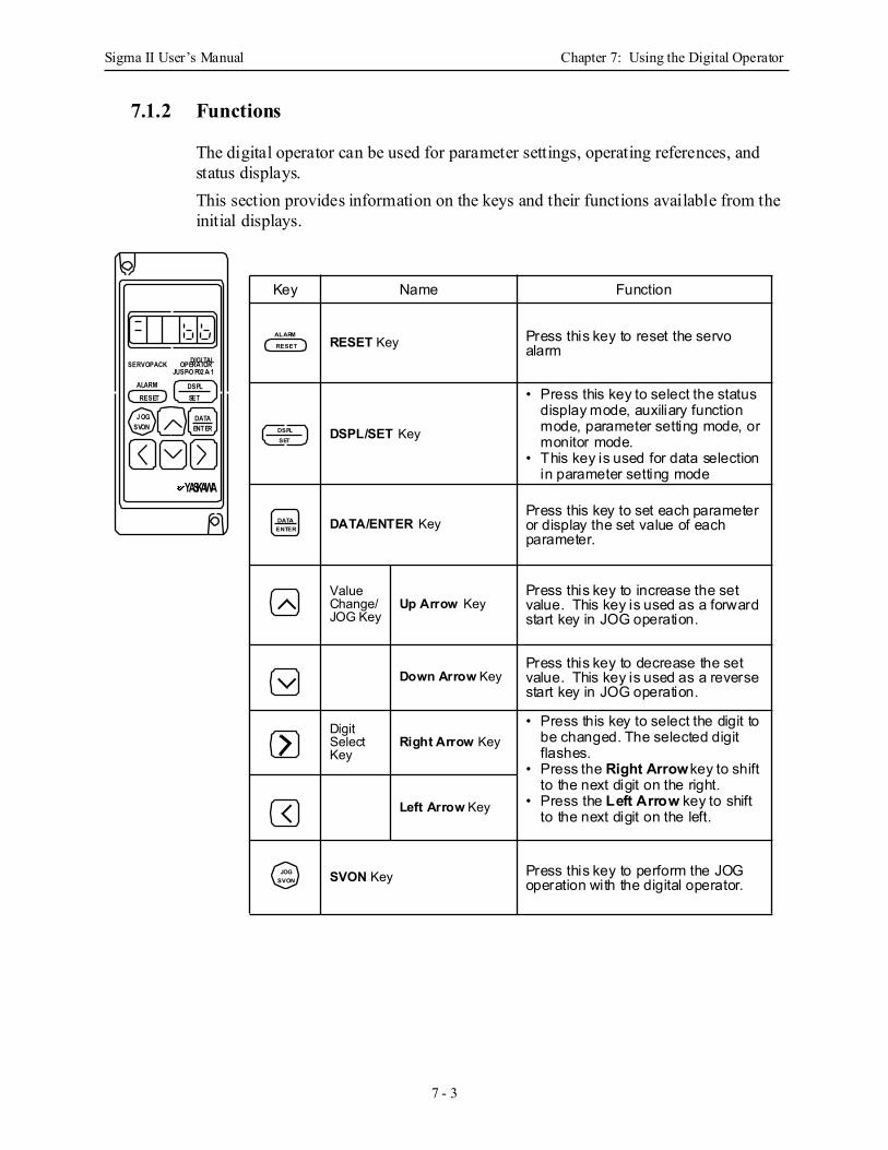
Sigma II User’s Manual Chapter 7: Using the Digital Operator
7 - 3
7.1.2 Functions
The digital operator can be used for parameter settings, operating references, and status displays.This section provides information on the keys and their functions available from the initial displays.
Key Name Function
RESET Key Press this key to reset the servo alarm
DSPL/SET Key
• Press this key to select the status display mode, auxiliary function mode, parameter setting mode, or monitor mode.
• This key is used for data selection in parameter setting mode
DATA/ENTER KeyPress this key to set each parameter or display the set value of each parameter.
Value Change/JOG Key
Up Arrow KeyPress this key to increase the set value. This key is used as a forward start key in JOG operation.
Down Arrow KeyPress this key to decrease the set value. This key is used as a reverse start key in JOG operation.
Digit Select Key
Right Arrow Key• Press this key to select the digit to
be changed. The selected digit flashes.
• Press the Right Arrow key to shift to the next digit on the right.
• Press the Left Arrow key to shift to the next digit on the left.
Left Arrow Key
SVON Key Press this key to perform the JOG operation with the digital operator.
ALARM
RESET
DSPLSET
DATAENTER
JOGSVON
SERVOPACK
ALARM
RESET
DIGI TALOPERATORJUSP-O P02 A- 1
DSPLSET
DATAENTER
J OGSVON
YASKAWA

Sigma II User’s Manual Chapter 7: Using the Digital Operator
7 - 4
SGDM-
MODE/SET DATA/
SERVOPACK200VYASKAWA
Built-in Panel Operator
Key Name Function
Up Arrow Key
• Press this key to set parame-ters or display the set values of parameters.
• Press the Up Arrow key to increase the set value.
• Press the Down Arrow key to decrease the set value.
• Press the Up and Down Arrow keys together to reset a servo alarm.
Down Arrow Key
MODE/SET KeyPress this key to select the status indicator mode, auxiliary function mode, parameter setting mode, or monitor mode.
DATA/SHIFT Key
• Press this key to set each parameter or display the set value of each parameter.
• This key is used for selecting the editing (flashing) digit or data setting.
MODE/SET
DATA/
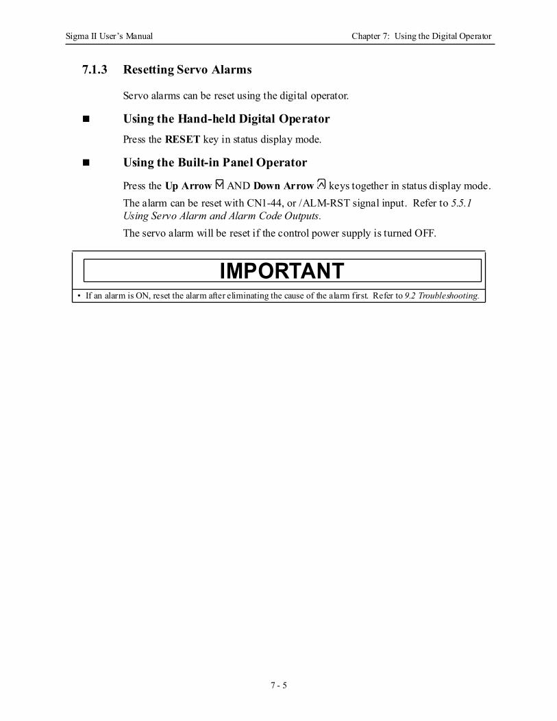
Sigma II User’s Manual Chapter 7: Using the Digital Operator
7 - 5
7.1.3 Resetting Servo Alarms
Servo alarms can be reset using the digital operator.
Using the Hand-held Digital OperatorPress the RESET key in status display mode.
Using the Built-in Panel Operator
Press the Up Arrow AND Down Arrow keys together in status display mode.The alarm can be reset with CN1-44, or /ALM-RST signal input. Refer to 5.5.1 Using Servo Alarm and Alarm Code Outputs.The servo alarm will be reset if the control power supply is turned OFF.
• If an alarm is ON, reset the alarm after eliminating the cause of the alarm first. Refer to 9.2 Troubleshooting.
IMPORTANT
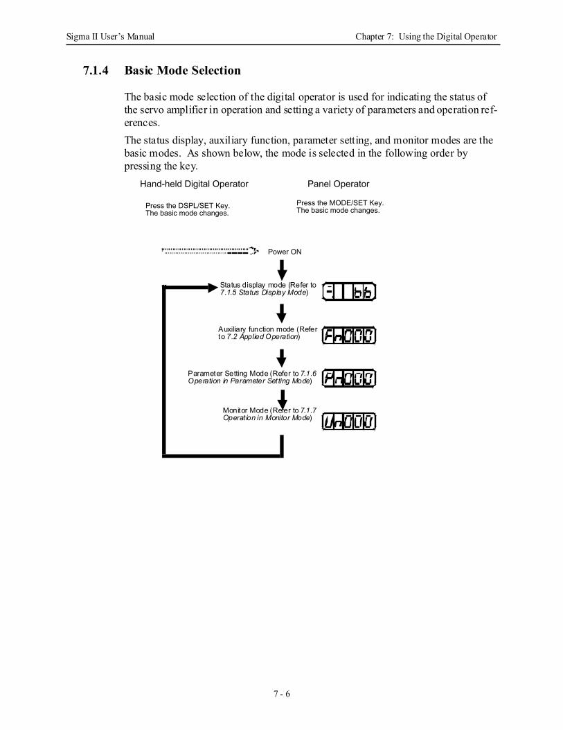
Sigma II User’s Manual Chapter 7: Using the Digital Operator
7 - 6
7.1.4 Basic Mode Selection
The basic mode selection of the digital operator is used for indicating the status of the servo amplifier in operation and setting a variety of parameters and operation ref-erences.The status display, auxiliary function, parameter setting, and monitor modes are the basic modes. As shown below, the mode is selected in the following order by pressing the key.
Power ON
Hand-held Digital Operator Panel Operator
Press the DSPL/SET Key.The basic mode changes.
Press the MODE/SET Key.The basic mode changes.
Status display mode (Refer to7.1.5 Status Display Mode)
Auxiliary function mode (Referto 7.2 Applied Operation)
Parameter Setting Mode (Refer to 7.1.6Operation in Parameter Setting Mode)
Monitor Mode (Refer to 7.1.7Operat ion in Monitor Mode)
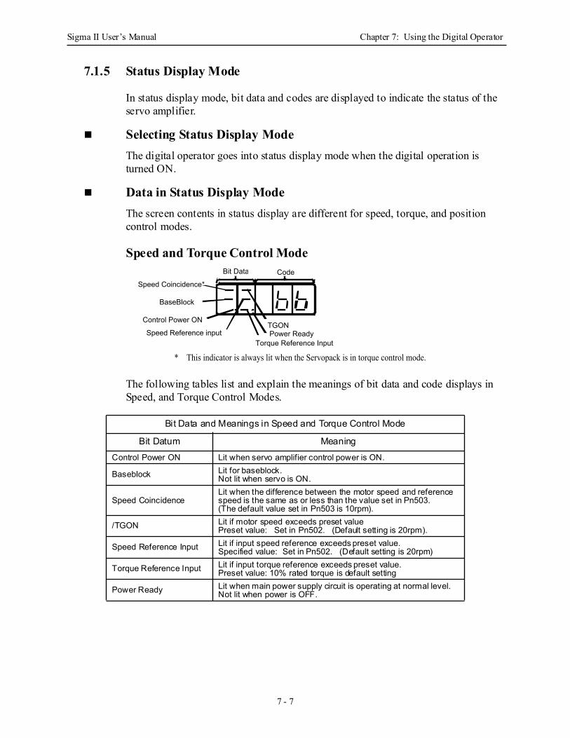
Sigma II User’s Manual Chapter 7: Using the Digital Operator
7 - 7
7.1.5 Status Display Mode
In status display mode, bit data and codes are displayed to indicate the status of the servo amplifier.
Selecting Status Display ModeThe digital operator goes into status display mode when the digital operation is turned ON.
Data in Status Display ModeThe screen contents in status display are different for speed, torque, and position control modes.
Speed and Torque Control Mode
The following tables list and explain the meanings of bit data and code displays in Speed, and Torque Control Modes.
Bit Data and Meanings in Speed and Torque Control Mode
Bit Datum MeaningControl Power ON Lit when servo amplifier control power is ON.
Baseblock Lit for baseblock.Not lit when servo is ON.
Speed CoincidenceLit when the difference between the motor speed and reference speed is the same as or less than the value set in Pn503.(The default value set in Pn503 is 10rpm).
/TGON Lit if motor speed exceeds preset valuePreset value: Set in Pn502. (Default setting is 20rpm).
Speed Reference Input Lit if input speed reference exceeds preset value.Specified value: Set in Pn502. (Default setting is 20rpm)
Torque Reference Input Lit if input torque reference exceeds preset value.Preset value: 10% rated torque is default setting
Power Ready Lit when main power supply circuit is operating at normal level. Not lit when power is OFF.
Bit Data CodeSpeed Coincidence*
Speed Reference input
BaseBlock
Control Power ONTGON
Torque Reference InputPower Ready
* This indicator is always lit when the Servopack is in torque control mode.
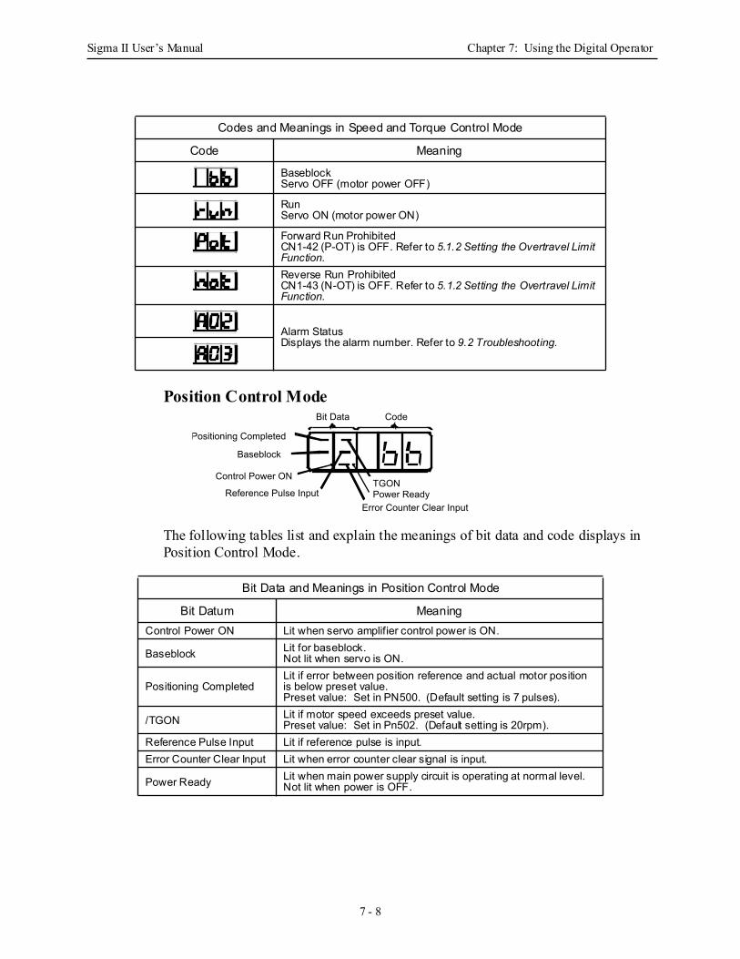
Sigma II User’s Manual Chapter 7: Using the Digital Operator
7 - 8
Position Control Mode
The following tables list and explain the meanings of bit data and code displays in Position Control Mode.
Codes and Meanings in Speed and Torque Control Mode
Code Meaning
BaseblockServo OFF (motor power OFF)
RunServo ON (motor power ON)
Forward Run ProhibitedCN1-42 (P-OT) is OFF. Refer to 5.1.2 Setting the Overtravel Limit Function.Reverse Run ProhibitedCN1-43 (N-OT) is OFF. Refer to 5.1.2 Setting the Overtravel Limit Function.
Alarm StatusDisplays the alarm number. Refer to 9.2 Troubleshooting.
Bit Data and Meanings in Position Control Mode
Bit Datum MeaningControl Power ON Lit when servo amplifier control power is ON.
Baseblock Lit for baseblock.Not lit when servo is ON.
Positioning Completed Lit if error between position reference and actual motor position is below preset value.Preset value: Set in PN500. (Default setting is 7 pulses).
/TGON Lit if motor speed exceeds preset value.Preset value: Set in Pn502. (Default setting is 20rpm).
Reference Pulse Input Lit if reference pulse is input.Error Counter Clear Input Lit when error counter clear signal is input.
Power Ready Lit when main power supply circuit is operating at normal level. Not lit when power is OFF.
CodeBit Data
Positioning Completed
Baseblock
Control Power ON
Reference Pulse InputTGONPower Ready
Error Counter Clear Input
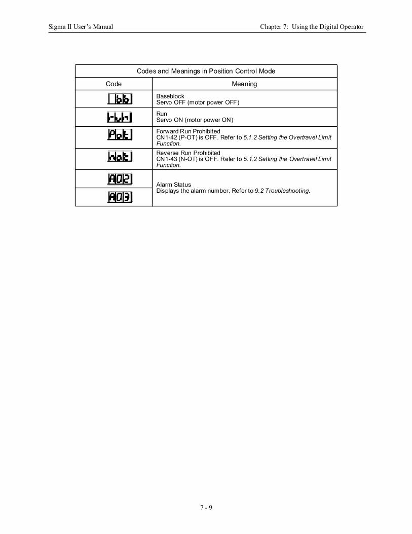
Sigma II User’s Manual Chapter 7: Using the Digital Operator
7 - 9
Codes and Meanings in Position Control Mode
Code Meaning
BaseblockServo OFF (motor power OFF)
RunServo ON (motor power ON)
Forward Run ProhibitedCN1-42 (P-OT) is OFF. Refer to 5.1.2 Setting the Overtravel Limit Function.Reverse Run ProhibitedCN1-43 (N-OT) is OFF. Refer to 5.1.2 Setting the Overtravel Limit Function.
Alarm StatusDisplays the alarm number. Refer to 9.2 Troubleshooting.
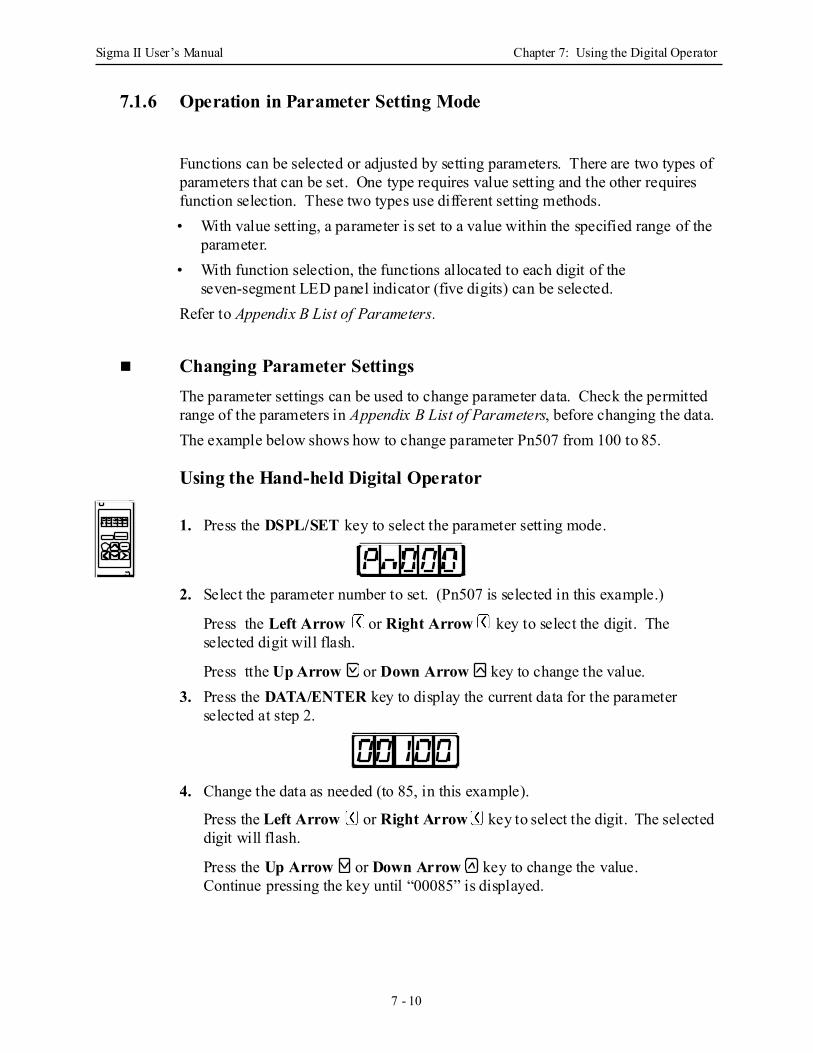
Sigma II User’s Manual Chapter 7: Using the Digital Operator
7 - 10
7.1.6 Operation in Parameter Setting Mode
Functions can be selected or adjusted by setting parameters. There are two types of parameters that can be set. One type requires value setting and the other requires function selection. These two types use different setting methods.• With value setting, a parameter is set to a value within the specified range of the
parameter.• With function selection, the functions allocated to each digit of the
seven-segment LED panel indicator (five digits) can be selected. Refer to Appendix B List of Parameters.
Changing Parameter Settings The parameter settings can be used to change parameter data. Check the permitted range of the parameters in Appendix B List of Parameters, before changing the data. The example below shows how to change parameter Pn507 from 100 to 85.
Using the Hand-held Digital Operator
1. Press the DSPL/SET key to select the parameter setting mode.
2. Select the parameter number to set. (Pn507 is selected in this example.)
Press the Left Arrow or Right Arrow key to select the digit. The selected digit will flash.
Press tthe Up Arrow or Down Arrow key to change the value.3. Press the DATA/ENTER key to display the current data for the parameter
selected at step 2.
4. Change the data as needed (to 85, in this example).
Press the Left Arrow or Right Arrow key to select the digit. The selected digit will flash.
Press the Up Arrow or Down Arrow key to change the value. Continue pressing the key until “00085” is displayed.
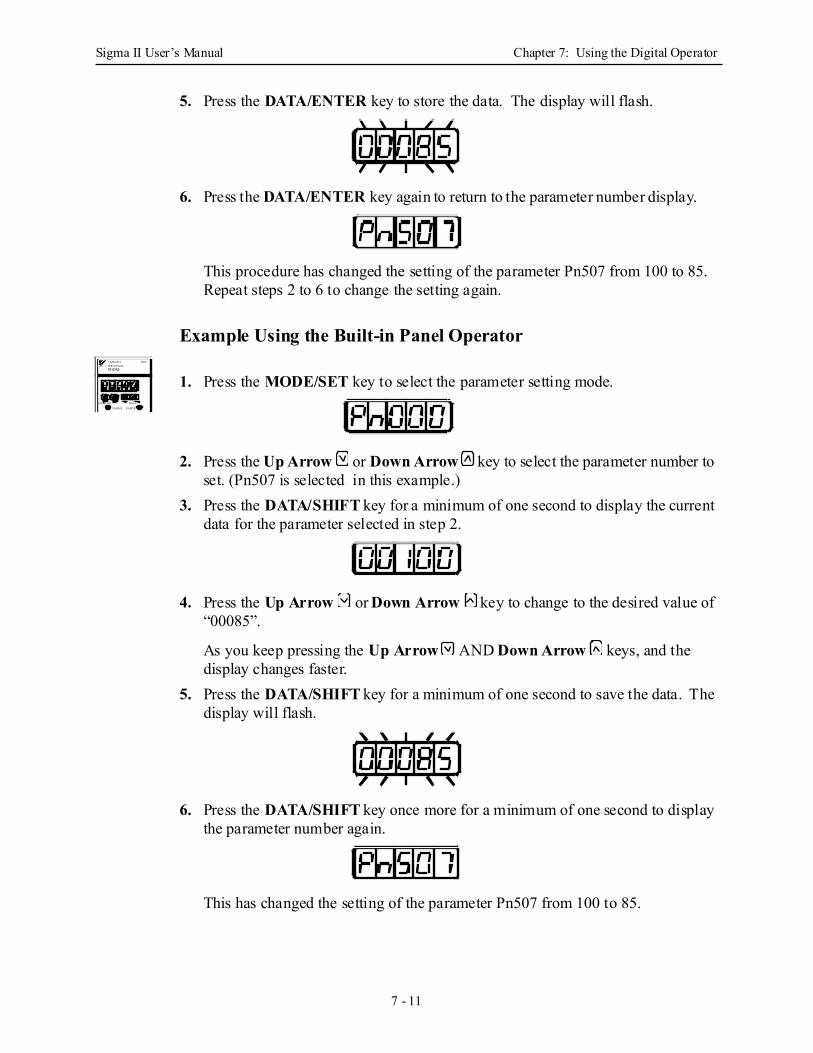
Sigma II User’s Manual Chapter 7: Using the Digital Operator
7 - 11
5. Press the DATA/ENTER key to store the data. The display will flash.
6. Press the DATA/ENTER key again to return to the parameter number display.
This procedure has changed the setting of the parameter Pn507 from 100 to 85. Repeat steps 2 to 6 to change the setting again.
Example Using the Built-in Panel Operator
1. Press the MODE/SET key to select the parameter setting mode.
2. Press the Up Arrow or Down Arrow key to select the parameter number to set. (Pn507 is selected in this example.)
3. Press the DATA/SHIFT key for a minimum of one second to display the current data for the parameter selected in step 2.
4. Press the Up Arrow or Down Arrow key to change to the desired value of “00085”.
As you keep pressing the Up Arrow AND Down Arrow keys, and the display changes faster.
5. Press the DATA/SHIFT key for a minimum of one second to save the data. The display will flash.
6. Press the DATA/SHIFT key once more for a minimum of one second to display the parameter number again.
This has changed the setting of the parameter Pn507 from 100 to 85.
SGDM-
MODE/SET DATA/
CHARGE POWER
SERVOPACK200VYASKAWA

Sigma II User’s Manual Chapter 7: Using the Digital Operator
7 - 12
Repeat steps 2 to 6 to change the setting again.Note: Parameter numbers that are not defined are skipped during Operator operations.
• Press the DATA/SHIFT Key for a maximum of one second to shift to a higher (left) digit.
IMPORTANT
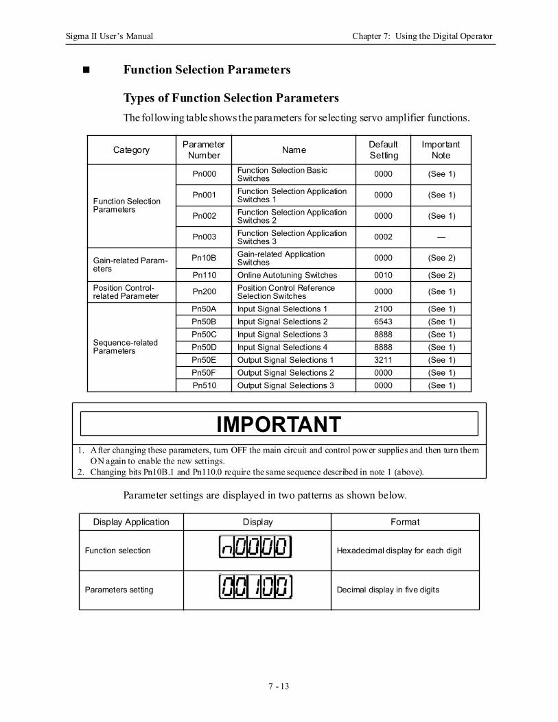
Sigma II User’s Manual Chapter 7: Using the Digital Operator
7 - 13
Function Selection Parameters
Types of Function Selection Parameters The following table shows the parameters for selecting servo amplifier functions.
Parameter settings are displayed in two patterns as shown below.
Category Parameter Number Name Default
SettingImportant
Note
Function Selection Parameters
Pn000 Function Selection Basic Switches 0000 (See 1)
Pn001 Function Selection Application Switches 1 0000 (See 1)
Pn002 Function Selection Application Switches 2 0000 (See 1)
Pn003 Function Selection Application Switches 3 0002 —
Gain-related Param-eters
Pn10B Gain-related Application Switches 0000 (See 2)
Pn110 Online Autotuning Switches 0010 (See 2)Position Control-related Parameter Pn200 Position Control Reference
Selection Switches 0000 (See 1)
Sequence-related Parameters
Pn50A Input Signal Selections 1 2100 (See 1)Pn50B Input Signal Selections 2 6543 (See 1)Pn50C Input Signal Selections 3 8888 (See 1)Pn50D Input Signal Selections 4 8888 (See 1)Pn50E Output Signal Selections 1 3211 (See 1)Pn50F Output Signal Selections 2 0000 (See 1)Pn510 Output Signal Selections 3 0000 (See 1)
1. After changing these parameters, turn OFF the main circuit and control power supplies and then turn them ON again to enable the new settings.
2. Changing bits Pn10B.1 and Pn110.0 require the same sequence described in note 1 (above).
Display Application Display Format
Function selection Hexadecimal display for each digit
Parameters setting Decimal display in five digits
IMPORTANT
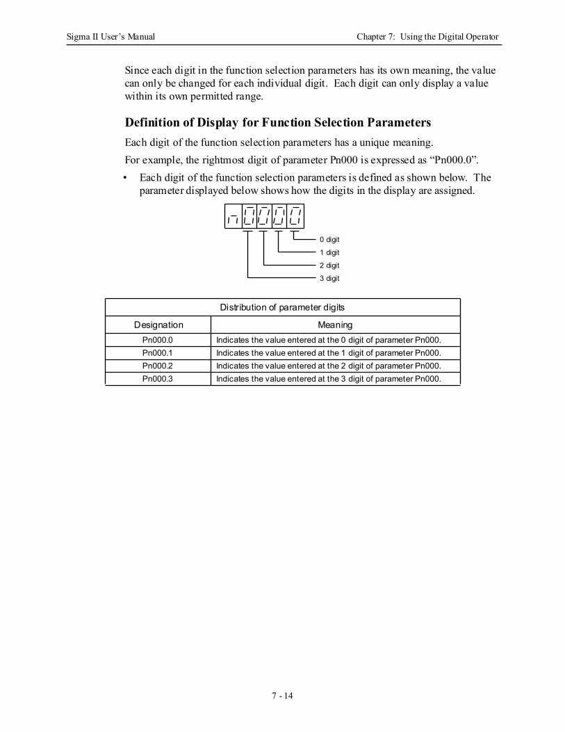
Sigma II User’s Manual Chapter 7: Using the Digital Operator
7 - 14
Since each digit in the function selection parameters has its own meaning, the value can only be changed for each individual digit. Each digit can only display a value within its own permitted range.
Definition of Display for Function Selection Parameters Each digit of the function selection parameters has a unique meaning.For example, the rightmost digit of parameter Pn000 is expressed as “Pn000.0”.• Each digit of the function selection parameters is defined as shown below. The
parameter displayed below shows how the digits in the display are assigned.
Distribution of parameter digits
Designation MeaningPn000.0 Indicates the value entered at the 0 digit of parameter Pn000.Pn000.1 Indicates the value entered at the 1 digit of parameter Pn000.Pn000.2 Indicates the value entered at the 2 digit of parameter Pn000.Pn000.3 Indicates the value entered at the 3 digit of parameter Pn000.
1 digit
0 digit
2 digit
3 digit
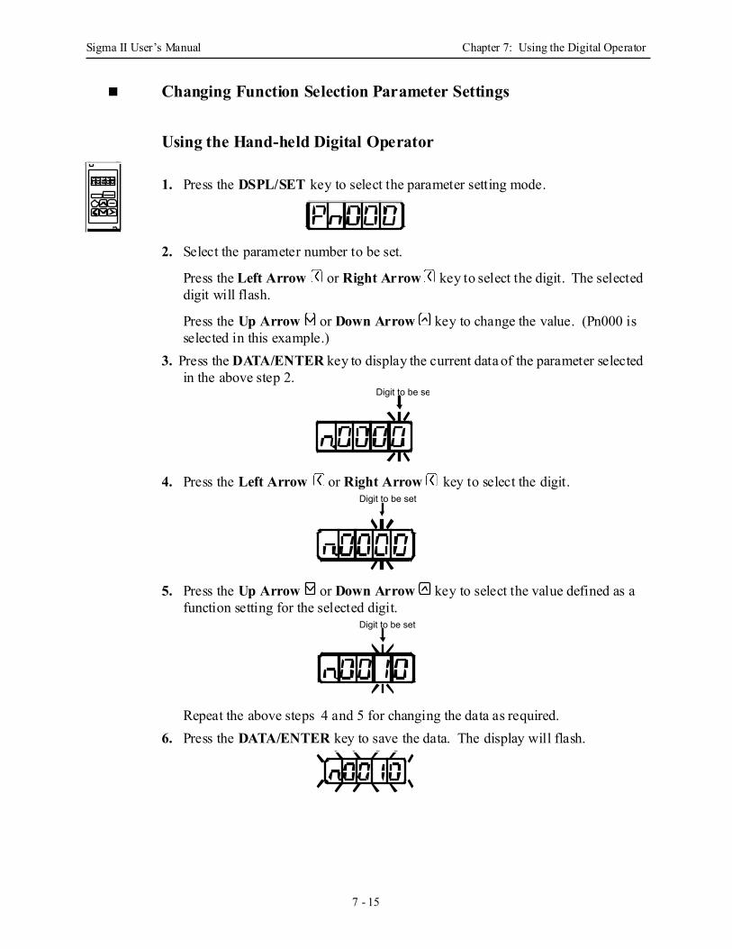
Sigma II User’s Manual Chapter 7: Using the Digital Operator
7 - 15
Changing Function Selection Parameter Settings
Using the Hand-held Digital Operator
1. Press the DSPL/SET key to select the parameter setting mode.
2. Select the parameter number to be set.
Press the Left Arrow or Right Arrow key to select the digit. The selected digit will flash.
Press the Up Arrow or Down Arrow key to change the value. (Pn000 is selected in this example.)
3. Press the DATA/ENTER key to display the current data of the parameter selected in the above step 2.
4. Press the Left Arrow or Right Arrow key to select the digit.
5. Press the Up Arrow or Down Arrow key to select the value defined as a function setting for the selected digit.
Repeat the above steps 4 and 5 for changing the data as required.6. Press the DATA/ENTER key to save the data. The display will flash.
Digit to be se
Digit to be set
Digit to be set
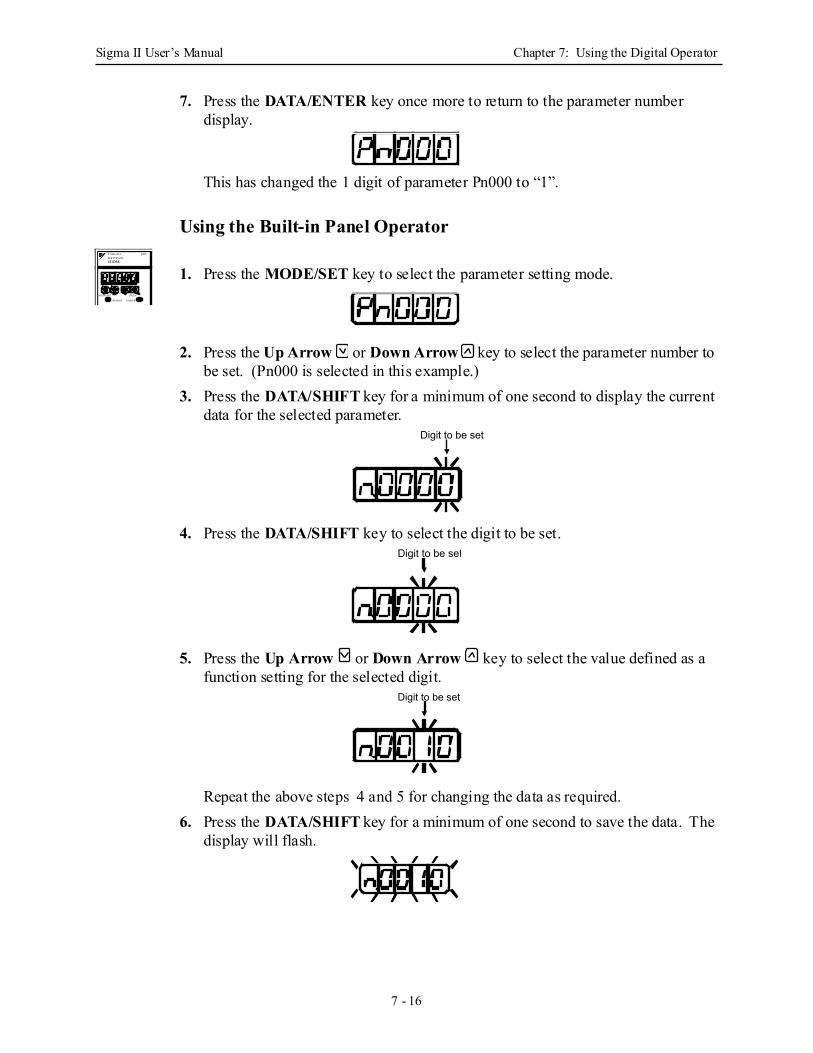
Sigma II User’s Manual Chapter 7: Using the Digital Operator
7 - 16
7. Press the DATA/ENTER key once more to return to the parameter number display.
This has changed the 1 digit of parameter Pn000 to “1”.
Using the Built-in Panel Operator
1. Press the MODE/SET key to select the parameter setting mode.
2. Press the Up Arrow or Down Arrow key to select the parameter number to be set. (Pn000 is selected in this example.)
3. Press the DATA/SHIFT key for a minimum of one second to display the current data for the selected parameter.
4. Press the DATA/SHIFT key to select the digit to be set.
5. Press the Up Arrow or Down Arrow key to select the value defined as a function setting for the selected digit.
Repeat the above steps 4 and 5 for changing the data as required.6. Press the DATA/SHIFT key for a minimum of one second to save the data. The
display will flash.
SGDM-
MODE/SET DATA/
CHARGE POWER
SERVOPACK200VYASKAWA
Digit to be set
Digit to be set
Digit to be set

Sigma II User’s Manual Chapter 7: Using the Digital Operator
7 - 17
7. Press the DATA/SHIFT key once more for a minimum of one second to return to the parameter number display.
This has changed the 1 digit of parameter Pn000 to “1”.
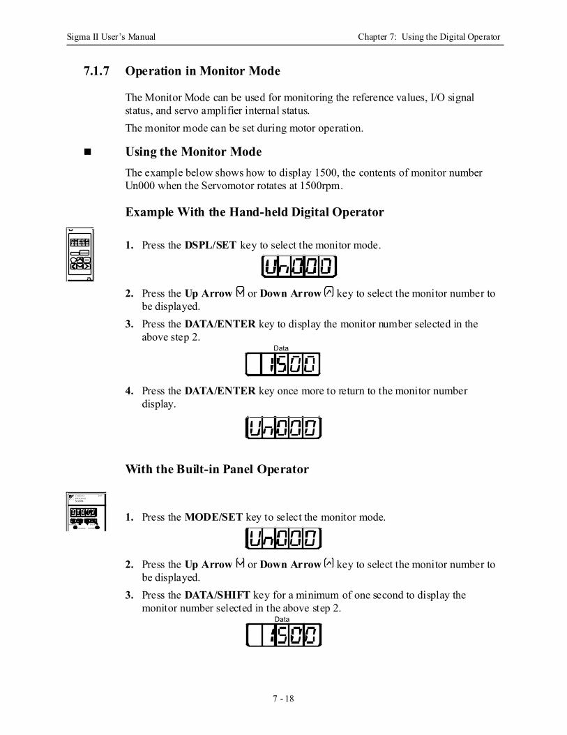
Sigma II User’s Manual Chapter 7: Using the Digital Operator
7 - 18
7.1.7 Operation in Monitor Mode
The Monitor Mode can be used for monitoring the reference values, I/O signal status, and servo amplifier internal status.The monitor mode can be set during motor operation.
Using the Monitor ModeThe example below shows how to display 1500, the contents of monitor number Un000 when the Servomotor rotates at 1500rpm.
Example With the Hand-held Digital Operator
1. Press the DSPL/SET key to select the monitor mode.
2. Press the Up Arrow or Down Arrow key to select the monitor number to be displayed.
3. Press the DATA/ENTER key to display the monitor number selected in the above step 2.
4. Press the DATA/ENTER key once more to return to the monitor number display.
With the Built-in Panel Operator
1. Press the MODE/SET key to select the monitor mode.
2. Press the Up Arrow or Down Arrow key to select the monitor number to be displayed.
3. Press the DATA/SHIFT key for a minimum of one second to display the monitor number selected in the above step 2.
Data
SGDM-
MODE/SET DATA/
CHARGE POWER
SERVOPACK200VYASKAWA
Data
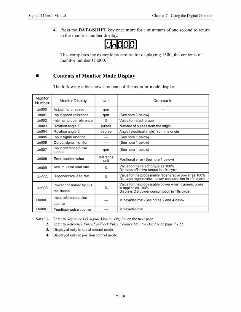
Sigma II User’s Manual Chapter 7: Using the Digital Operator
7 - 19
4. Press the DATA/SHIFT key once more for a minimum of one second to return to the monitor number display.
This completes the example procedure for displaying 1500, the contents of monitor number Un000.
Contents of Monitor Mode Display
The following table shows contents of the monitor mode display.
Note: 1. Refer to Sequence I/O Signal Monitor Display on the next page.2. Refer to Reference Pulse/Feedback Pulse Counter Monitor Display on page 7 - 22.3. Displayed only in speed control mode.4. Displayed only in position control mode.
Monitor Number Monitor Display Unit Comments
Un000 Actual motor speed rpm —Un001 Input speed reference rpm (See note 3 below)Un002 Internal torque reference % Value for rated torqueUn003 Rotation angle 1 pulses Number of pulses from the originUn004 Rotation angle 2 degree Angle (electrical angle) from the originUn005 Input signal monitor — (See note 1 below)Un006 Output signal monitor — (See note 1 below)
Un007 Input reference pulse speed rpm (See note 4 below)
Un008 Error counter value reference unit Positional error (See note 4 below)
Un009 Accumulated load rate % Value for the rated torque as 100%Displays effective torque in 10s cycle.
Un00A Regenerative load rate % Value for the processable regenerative power as 100%Displays regenerative power consumption in 10s cycle.
Un00BPower consumed by DB resistance
%Value for the processable power when dynamic brake is applied as 100%Displays DB power consumption in 10s cycle.
Un00C Input reference pulse counter
— In hexadecimal (See notes 2 and 4)below
Un00D Feedback pulse counter — In hexadecimal
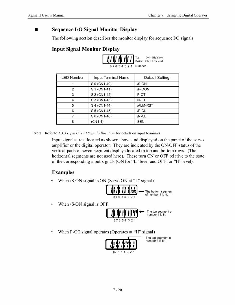
Sigma II User’s Manual Chapter 7: Using the Digital Operator
7 - 20
Sequence I/O Signal Monitor Display The following section describes the monitor display for sequence I/O signals.
Input Signal Monitor Display
Note Refer to 5.3.3 Input Circuit Signal Allocation for details on input terminals.
Input signals are allocated as shown above and displayed on the panel of the servo amplifier or the digital operator. They are indicated by the ON/OFF status of the vertical parts of seven-segment displays located in top and bottom rows. (The horizontal segments are not used here). These turn ON or OFF relative to the state of the corresponding input signals (ON for “L” level and OFF for “H” level).
Examples• When /S-ON signal is ON (Servo ON at “L” signal)
• When /S-ON signal is OFF
• When P-OT signal operates (Operates at “H” signal)
LED Number Input Terminal Name Default Setting1 SI0 (CN1-40) /S-ON2 SI1 (CN1-41) /P-CON3 SI2 (CN1-42) P-OT4 SI3 (CN1-43) N-OT5 SI4 (CN1-44) /ALM-RST6 SI5 (CN1-45) /P-CL7 SI6 (CN1-46) /N-CL8 (CN1-4) SEN
7 6 5 4 3 2 1 Number8
Top: ON = High levelBottom: ON = Low level
The bottom segmentof number 1 is lit.
7 6 5 4 3 2 18
7 6 5 4 3 2 18
The top segment ofnumber 1 is lit.
The top segment ofnumber 3 is lit.
7 6 5 4 3 2 18
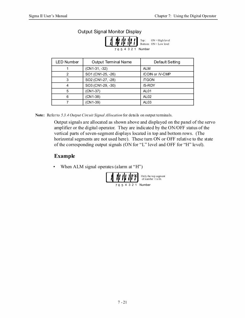
Sigma II User’s Manual Chapter 7: Using the Digital Operator
7 - 21
Output Signal Monitor Display
Note: Refer to 5.3.4 Output Circuit Signal Allocation for details on output terminals.
Output signals are allocated as shown above and displayed on the panel of the servo amplifier or the digital operator. They are indicated by the ON/OFF status of the vertical parts of seven-segment displays located in top and bottom rows. (The horizontal segments are not used here). These turn ON or OFF relative to the state of the corresponding output signals (ON for “L” level and OFF for “H” level).
Example
• When ALM signal operates (alarm at “H”)
LED Number Output Terminal Name Default Setting1 (CN1-31, -32) ALM2 SO1 (CN1-25, -26) /COIN or /V-CMP3 SO2 (CN1-27, -28) /TGON4 SO3 (CN1-29, -30) /S-RDY5 (CN1-37) AL016 (CN1-38) AL027 (CN1-39) AL03
4 3 2 1 Number7 6 5
Top: ON = High levelBottom: ON = Low level
4 3 2 1 Number7 6 5
Only the top segment of number 1 is lit.

Sigma II User’s Manual Chapter 7: Using the Digital Operator
7 - 22
Reference Pulse/Feedback Pulse Counter Monitor Display
The monitor display of reference pulse counter and feedback pulse counter is expressed in 32-bit hexadecimal.
The display procedure is as follows:
Using the Hand-held Digital Operator
1. Press the DSPL/SET key to select the monitor mode.
2. Press the Up Arrow or Down Arrow key to select “Un00C” or “Un00D”.3. Press the DATA/ENTER key to display the data for the monitor number
selected in the above step.
4. Press the Up Arrow or Down Arrow key to alternately display the leftmost and the rightmost 16-bit data.
5. Press both the Up Arrow AND Down Arrow keys simultaneously to clear the 32-bit counter data.
6. Press the DATA/ENTER key once more to return to the monitor number display.
Using the Built-in Panel Operator
1. Press the MODE/SET key to select the monitor mode.
2. Press the Up Arrow AND Down Arrow keys to select “Un00C” or “Un00D”.
3. Press the DATA/SHIFT key for a minimum of one second to display the data for the monitor number selected in the above step.
4. Press the Up Arrow or Down Arrow key to alternately display the leftmost 16-bit data and rightmost 16-bit data.
Leftmost 16-bit Data Rightmost 16-bit Data
SGDM-
MODE/SET DATA/
CHARGE POWER
SERVOPACK200VYASKAWA
Leftmost 16-bit Data Rightmost 16-bit Data

Sigma II User’s Manual Chapter 7: Using the Digital Operator
7 - 23
5. Press both the Up Arrow AND Down Arrow keys simultaneously to clear the 32-bit counter data.
6. Press the DATA/SHIFT key once more for a minimum of one second to return to the monitor number display.
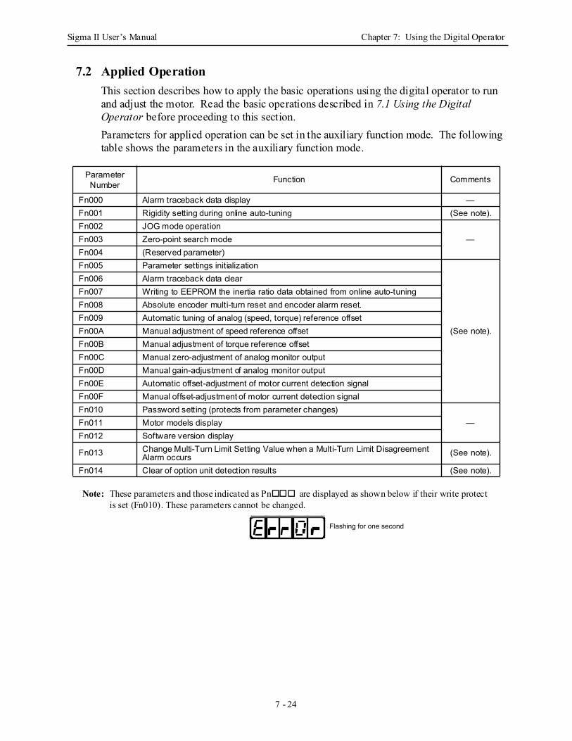
Sigma II User’s Manual Chapter 7: Using the Digital Operator
7 - 24
7.2 Applied OperationThis section describes how to apply the basic operations using the digital operator to run and adjust the motor. Read the basic operations described in 7.1 Using the Digital Operator before proceeding to this section.Parameters for applied operation can be set in the auxiliary function mode. The following table shows the parameters in the auxiliary function mode.
Note: These parameters and those indicated as Pn are displayed as shown below if their write protect is set (Fn010). These parameters cannot be changed.
Parameter Number Function Comments
Fn000 Alarm traceback data display —Fn001 Rigidity setting during online auto-tuning (See note).Fn002 JOG mode operation
—Fn003 Zero-point search modeFn004 (Reserved parameter)Fn005 Parameter settings initialization
(See note).
Fn006 Alarm traceback data clearFn007 Writing to EEPROM the inertia ratio data obtained from online auto-tuningFn008 Absolute encoder multi-turn reset and encoder alarm reset.Fn009 Automatic tuning of analog (speed, torque) reference offsetFn00A Manual adjustment of speed reference offsetFn00B Manual adjustment of torque reference offsetFn00C Manual zero-adjustment of analog monitor outputFn00D Manual gain-adjustment of analog monitor outputFn00E Automatic offset-adjustment of motor current detection signalFn00F Manual offset-adjustment of motor current detection signalFn010 Password setting (protects from parameter changes)
—Fn011 Motor models displayFn012 Software version display
Fn013 Change Multi-Turn Limit Setting Value when a Multi-Turn Limit Disagreement Alarm occurs (See note).
Fn014 Clear of option unit detection results (See note).
Flashing for one second
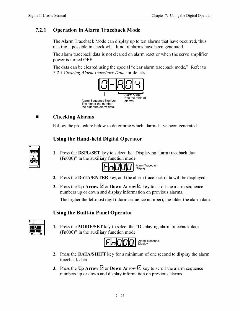
Sigma II User’s Manual Chapter 7: Using the Digital Operator
7 - 25
7.2.1 Operation in Alarm Traceback Mode
The Alarm Traceback Mode can display up to ten alarms that have occurred, thus making it possible to check what kind of alarms have been generated.The alarm traceback data is not cleared on alarm reset or when the servo amplifier power is turned OFF. The data can be cleared using the special “clear alarm traceback mode.” Refer to 7.2.5 Clearing Alarm Traceback Data for details.
Checking Alarms Follow the procedure below to determine which alarms have been generated.
Using the Hand-held Digital Operator
1. Press the DSPL/SET key to select the “Displaying alarm traceback data (Fn000)” in the auxiliary function mode.
2. Press the DATA/ENTER key, and the alarm traceback data will be displayed.
3. Press the Up Arrow or Down Arrow key to scroll the alarm sequence numbers up or down and display information on previous alarms.The higher the leftmost digit (alarm sequence number), the older the alarm data.
Using the Built-in Panel Operator
1. Press the MODE/SET key to select the “Displaying alarm traceback data (Fn000)” in the auxiliary function mode.
2. Press the DATA/SHIFT key for a minimum of one second to display the alarm traceback data.
3. Press the Up Arrow or Down Arrow key to scroll the alarm sequence numbers up or down and display information on previous alarms.
Alarm CodeSee the table of alarms.Alarm Sequence Number
The higher the number, the older the alarm data.
Alarm Traceback Display
SGDM-
MODE/SET DATA/
CHARGE POWER
SERVOPACK200VYASKAWA
Alarm Traceback Display
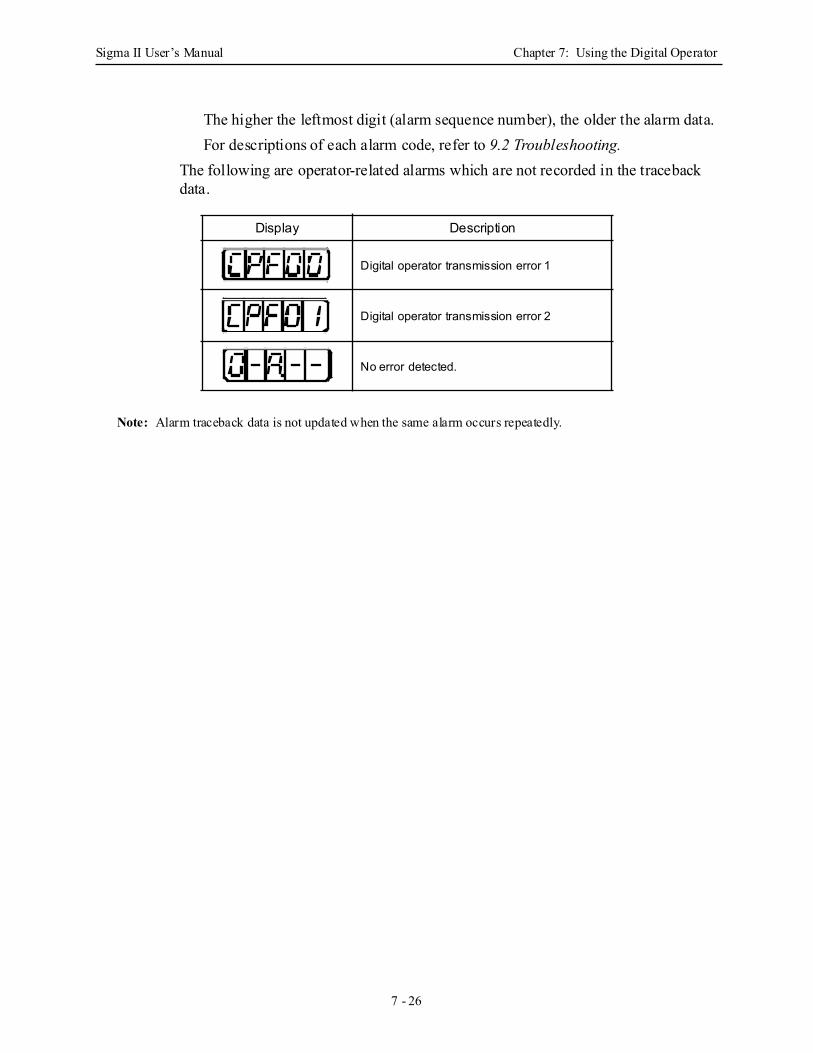
Sigma II User’s Manual Chapter 7: Using the Digital Operator
7 - 26
The higher the leftmost digit (alarm sequence number), the older the alarm data.For descriptions of each alarm code, refer to 9.2 Troubleshooting.
The following are operator-related alarms which are not recorded in the traceback data.
Note: Alarm traceback data is not updated when the same alarm occurs repeatedly.
Display Description
Digital operator transmission error 1
Digital operator transmission error 2
No error detected.
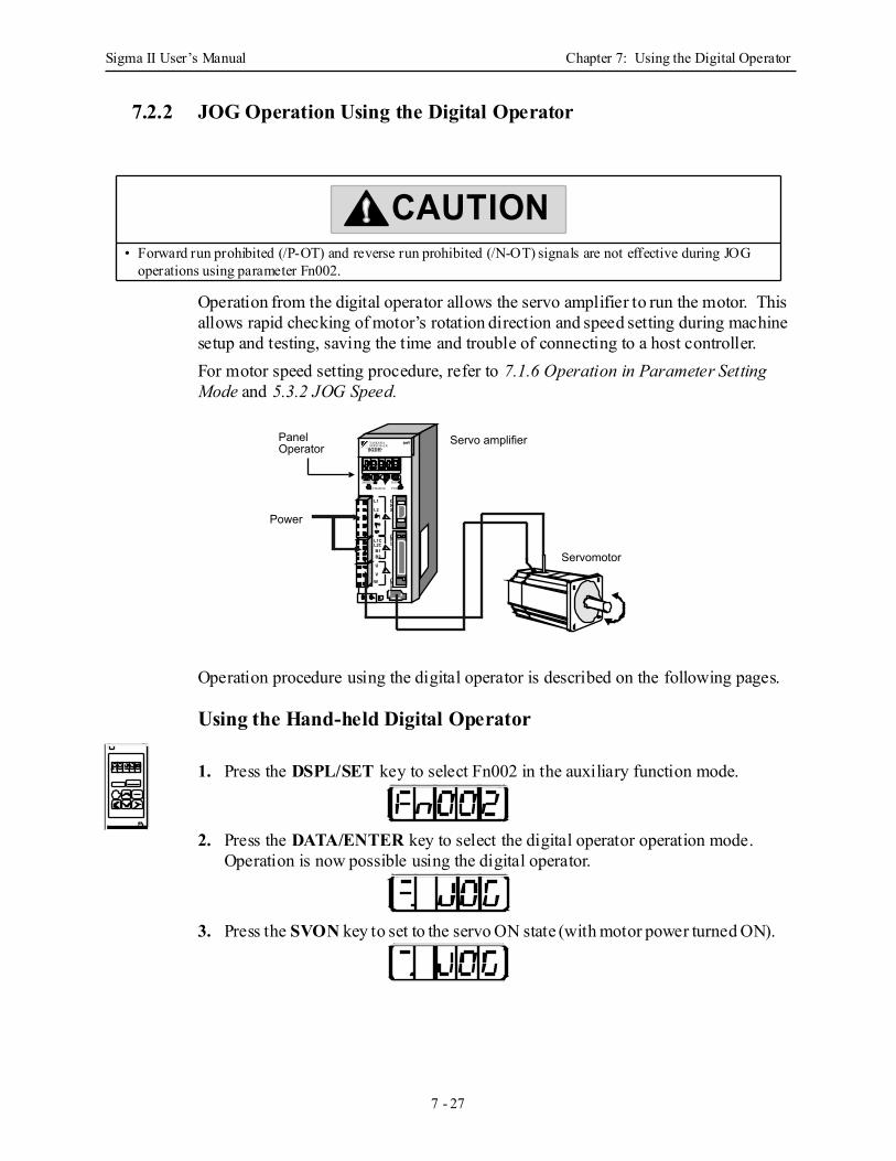
Sigma II User’s Manual Chapter 7: Using the Digital Operator
7 - 27
7.2.2 JOG Operation Using the Digital Operator
Operation from the digital operator allows the servo amplifier to run the motor. This allows rapid checking of motor’s rotation direction and speed setting during machine setup and testing, saving the time and trouble of connecting to a host controller. For motor speed setting procedure, refer to 7.1.6 Operation in Parameter Setting Mode and 5.3.2 JOG Speed.
Operation procedure using the digital operator is described on the following pages.
Using the Hand-held Digital Operator
1. Press the DSPL/SET key to select Fn002 in the auxiliary function mode.
2. Press the DATA/ENTER key to select the digital operator operation mode. Operation is now possible using the digital operator.
3. Press the SVON key to set to the servo ON state (with motor power turned ON).
• Forward run prohibited (/P-OT) and reverse run prohibited (/N-OT) signals are not effective during JOG operations using parameter Fn002.
CAUTION
CN3
CN1L1C
L2CB1B2
U
VW
L1
L212
CN2
SGDH-
MODE/SET DATA/
CHARGE POWER
SERVOPaCK200VYASKAWA
Power
Servo amplifier
Servomotor
Panel Operator
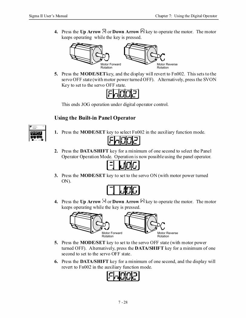
Sigma II User’s Manual Chapter 7: Using the Digital Operator
7 - 28
4. Press the Up Arrow or Down Arrow key to operate the motor. The motor keeps operating while the key is pressed.
5. Press the MODE/SET key, and the display will revert to Fn002. This sets to the servo OFF state (with motor power turned OFF). Alternatively, press the SVON Key to set to the servo OFF state.
This ends JOG operation under digital operator control.
Using the Built-in Panel Operator
1. Press the MODE/SET key to select Fn002 in the auxiliary function mode.
2. Press the DATA/SHIFT key for a minimum of one second to select the Panel Operator Operation Mode. Operation is now possible using the panel operator.
3. Press the MODE/SET key to set to the servo ON (with motor power turned ON).
4. Press the Up Arrow or Down Arrow key to operate the motor. The motor keeps operating while the key is pressed.
5. Press the MODE/SET key to set to the servo OFF state (with motor power turned OFF). Alternatively, press the DATA/SHIFT key for a minimum of one second to set to the servo OFF state.
6. Press the DATA/SHIFT key for a minimum of one second, and the display will revert to Fn002 in the auxiliary function mode.
Motor Forward Rotation
Motor Reverse Rotation
SGDM-
MODE/SET DATA/
CHARGE POWER
SERVOPACK200VYASKAWA
Motor Forward Rotation
Motor Reverse Rotation
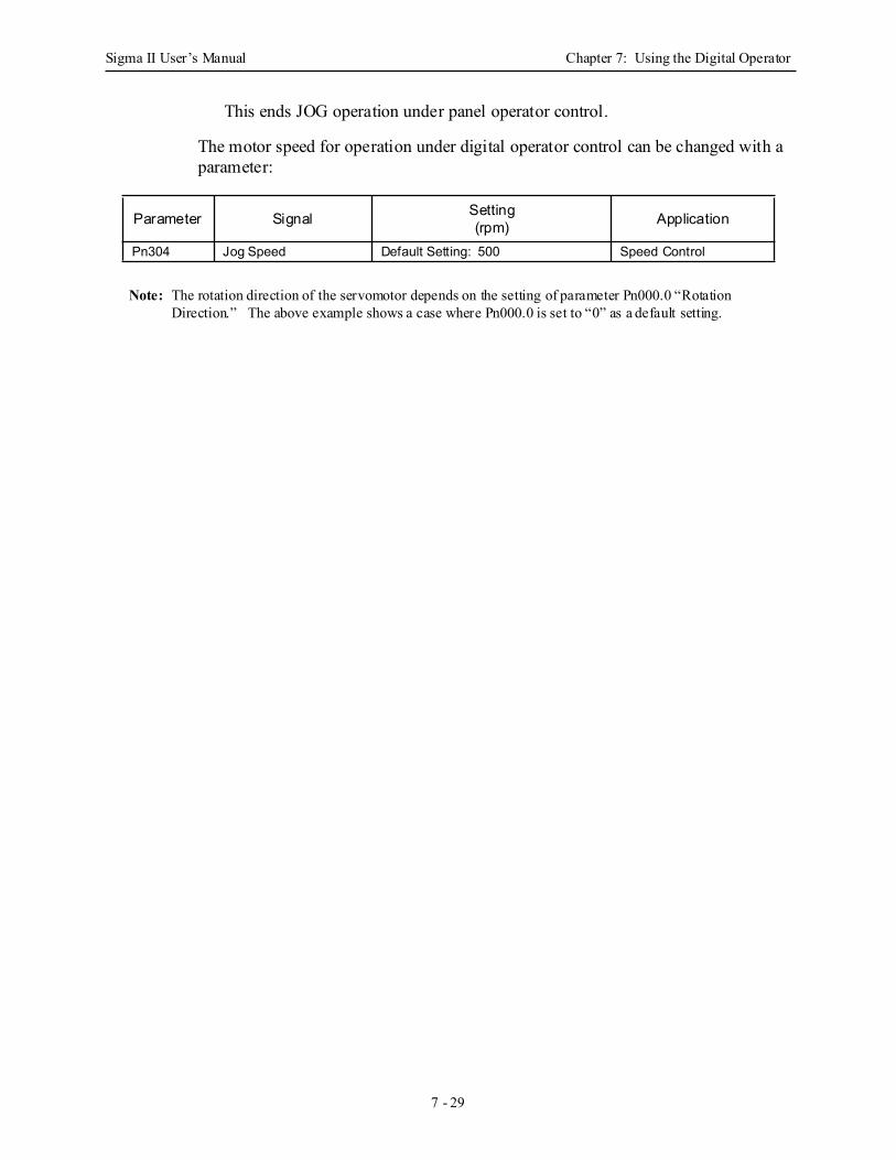
Sigma II User’s Manual Chapter 7: Using the Digital Operator
7 - 29
This ends JOG operation under panel operator control.
The motor speed for operation under digital operator control can be changed with a parameter:
Note: The rotation direction of the servomotor depends on the setting of parameter Pn000.0 “Rotation Direction.” The above example shows a case where Pn000.0 is set to “0” as a default setting.
Parameter Signal Setting(rpm) Application
Pn304 Jog Speed Default Setting: 500 Speed Control
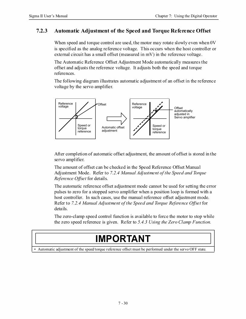
Sigma II User’s Manual Chapter 7: Using the Digital Operator
7 - 30
7.2.3 Automatic Adjustment of the Speed and Torque Reference Offset
When speed and torque control are used, the motor may rotate slowly even when 0V is specified as the analog reference voltage. This occurs when the host controller or external circuit has a small offset (measured in mV) in the reference voltage. The Automatic Reference Offset Adjustment Mode automatically measures the offset and adjusts the reference voltage. It adjusts both the speed and torque references. The following diagram illustrates automatic adjustment of an offset in the reference voltage by the servo amplifier.
After completion of automatic offset adjustment, the amount of offset is stored in the servo amplifier.The amount of offset can be checked in the Speed Reference Offset Manual Adjustment Mode. Refer to 7.2.4 Manual Adjustment of the Speed and Torque Reference Offset for details.The automatic reference offset adjustment mode cannot be used for setting the error pulses to zero for a stopped servo amplifier when a position loop is formed with a host controller. In such cases, use the manual reference offset adjustment mode. Refer to 7.2.4 Manual Adjustment of the Speed and Torque Reference Offset for details.The zero-clamp speed control function is available to force the motor to stop while the zero speed reference is given. Refer to 5.4.3 Using the Zero Clamp Function.
• Automatic adjustment of the speed/torque reference offset must be performed under the servo OFF state.
OffsetReference voltage
Reference voltage Offset
automatically adjusted in Servo amplifier
Automatic offset adjustment
Speed or torque reference
Speed or torque reference
IMPORTANT
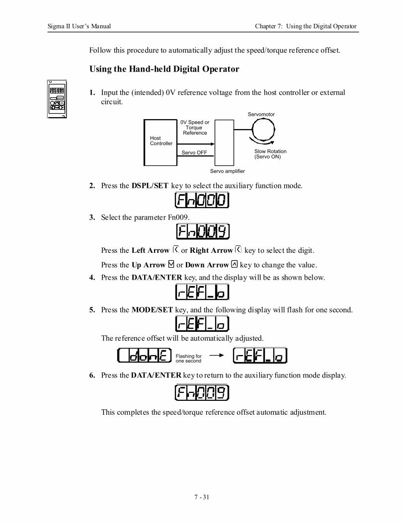
Sigma II User’s Manual Chapter 7: Using the Digital Operator
7 - 31
Follow this procedure to automatically adjust the speed/torque reference offset.
Using the Hand-held Digital Operator
1. Input the (intended) 0V reference voltage from the host controller or external circuit.
2. Press the DSPL/SET key to select the auxiliary function mode.
3. Select the parameter Fn009.
Press the Left Arrow or Right Arrow key to select the digit.
Press the Up Arrow or Down Arrow key to change the value.4. Press the DATA/ENTER key, and the display will be as shown below.
5. Press the MODE/SET key, and the following display will flash for one second.
The reference offset will be automatically adjusted.
6. Press the DATA/ENTER key to return to the auxiliary function mode display.
This completes the speed/torque reference offset automatic adjustment.
Servomotor
Slow Rotation (Servo ON)
Servo amplifier
Servo OFF
0V Speed or Torque
ReferenceHost Controller
Flashing for one second
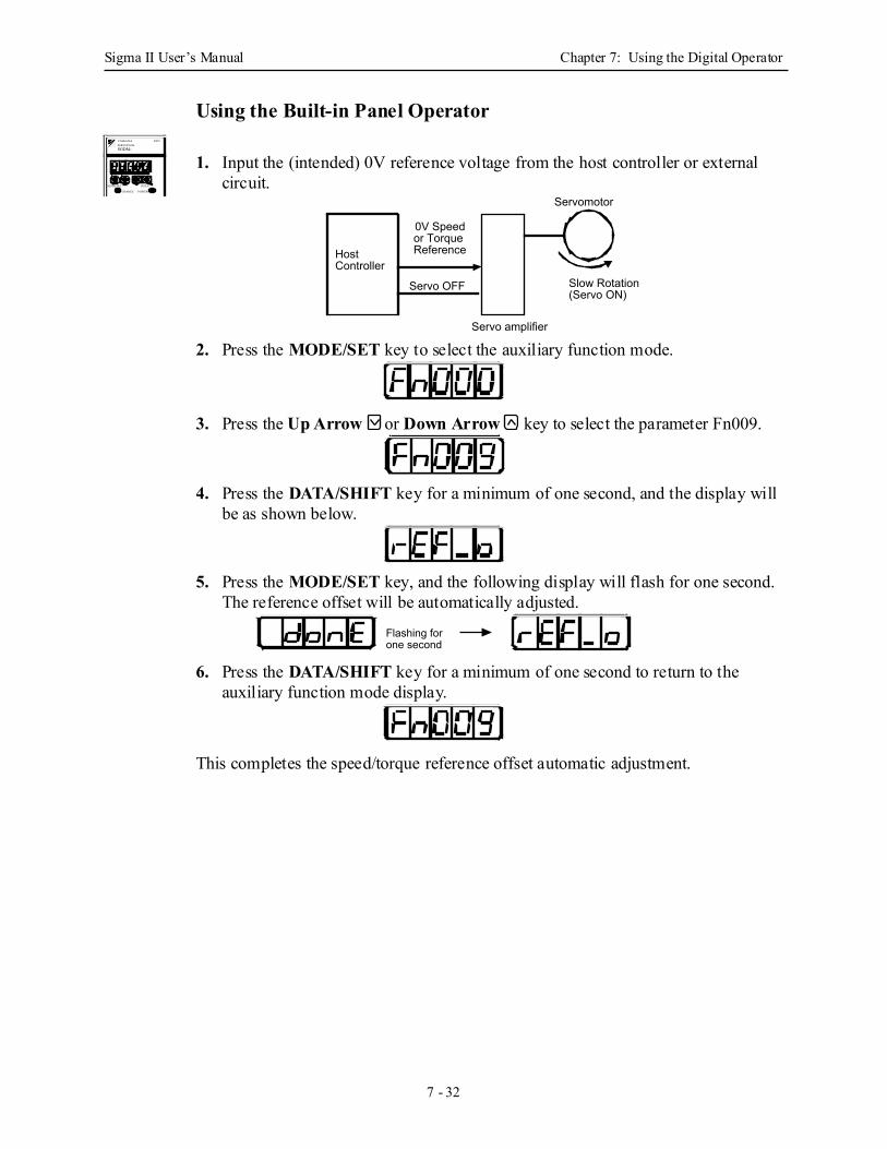
Sigma II User’s Manual Chapter 7: Using the Digital Operator
7 - 32
Using the Built-in Panel Operator
1. Input the (intended) 0V reference voltage from the host controller or external circuit.
2. Press the MODE/SET key to select the auxiliary function mode.
3. Press the Up Arrow or Down Arrow key to select the parameter Fn009.
4. Press the DATA/SHIFT key for a minimum of one second, and the display will be as shown below.
5. Press the MODE/SET key, and the following display will flash for one second. The reference offset will be automatically adjusted.
6. Press the DATA/SHIFT key for a minimum of one second to return to the auxiliary function mode display.
This completes the speed/torque reference offset automatic adjustment.
SGDM-
MODE/SET DATA/
CHARGE POWER
SERVOPACK200VYASKAWA
Servomotor
Slow Rotation (Servo ON)
Servo amplifier
Servo OFF
Host Controller
0V Speed or Torque Reference
Flashing for one second
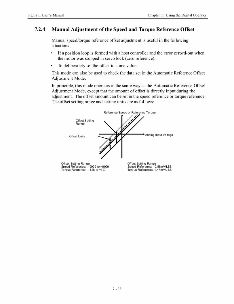
Sigma II User’s Manual Chapter 7: Using the Digital Operator
7 - 33
7.2.4 Manual Adjustment of the Speed and Torque Reference Offset
Manual speed/torque reference offset adjustment is useful in the following situations:• If a position loop is formed with a host controller and the error zeroed-out when
the motor was stopped in servo lock (zero reference).• To deliberately set the offset to some value. This mode can also be used to check the data set in the Automatic Reference Offset Adjustment Mode.In principle, this mode operates in the same way as the Automatic Reference Offset Adjustment Mode, except that the amount of offset is directly input during the adjustment. The offset amount can be set in the speed reference or torque reference. The offset setting range and setting units are as follows:
Reference Speed or Reference Torque
Offset Setting Range
Offset Units Analog Input Voltage
Offset Setting RangeSpeed Reference: -9999 to +9999Torque Reference:
Offset Setting RangeSpeed Reference: 0.58mV/LSBTorque Reference: 1.47mV/LSB-128 to +127
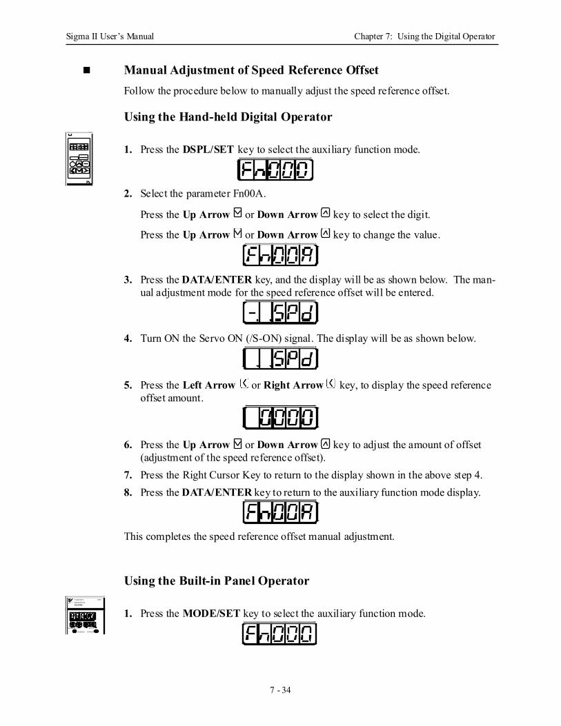
Sigma II User’s Manual Chapter 7: Using the Digital Operator
7 - 34
Manual Adjustment of Speed Reference Offset Follow the procedure below to manually adjust the speed reference offset.
Using the Hand-held Digital Operator
1. Press the DSPL/SET key to select the auxiliary function mode.
2. Select the parameter Fn00A.
Press the Up Arrow or Down Arrow key to select the digit.
Press the Up Arrow or Down Arrow key to change the value.
3. Press the DATA/ENTER key, and the display will be as shown below. The man-ual adjustment mode for the speed reference offset will be entered.
4. Turn ON the Servo ON (/S-ON) signal. The display will be as shown below.
5. Press the Left Arrow or Right Arrow key, to display the speed reference offset amount.
6. Press the Up Arrow or Down Arrow key to adjust the amount of offset (adjustment of the speed reference offset).
7. Press the Right Cursor Key to return to the display shown in the above step 4.8. Press the DATA/ENTER key to return to the auxiliary function mode display.
This completes the speed reference offset manual adjustment.
Using the Built-in Panel Operator
1. Press the MODE/SET key to select the auxiliary function mode. SGDM-
MODE/SET DATA/
CHARGE POWER
SERVOPACK200VYASKAWA
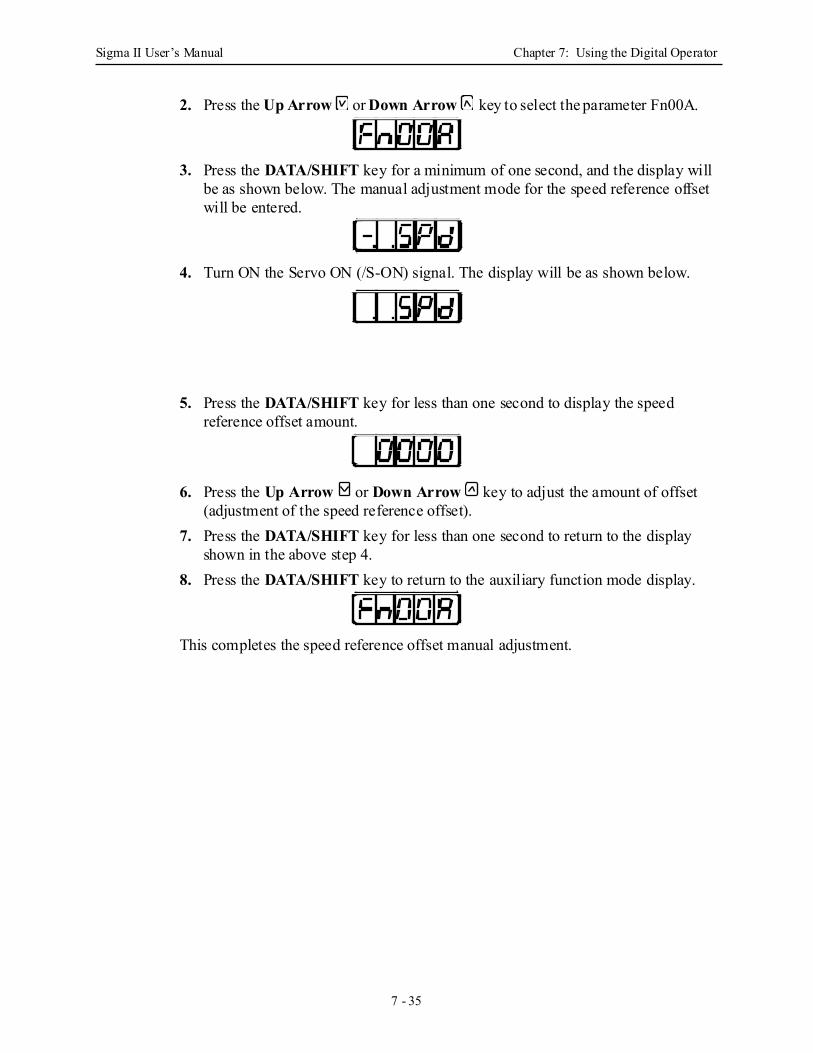
Sigma II User’s Manual Chapter 7: Using the Digital Operator
7 - 35
2. Press the Up Arrow or Down Arrow key to select the parameter Fn00A.
3. Press the DATA/SHIFT key for a minimum of one second, and the display will be as shown below. The manual adjustment mode for the speed reference offset will be entered.
4. Turn ON the Servo ON (/S-ON) signal. The display will be as shown below.
5. Press the DATA/SHIFT key for less than one second to display the speed reference offset amount.
6. Press the Up Arrow or Down Arrow key to adjust the amount of offset (adjustment of the speed reference offset).
7. Press the DATA/SHIFT key for less than one second to return to the display shown in the above step 4.
8. Press the DATA/SHIFT key to return to the auxiliary function mode display.
This completes the speed reference offset manual adjustment.
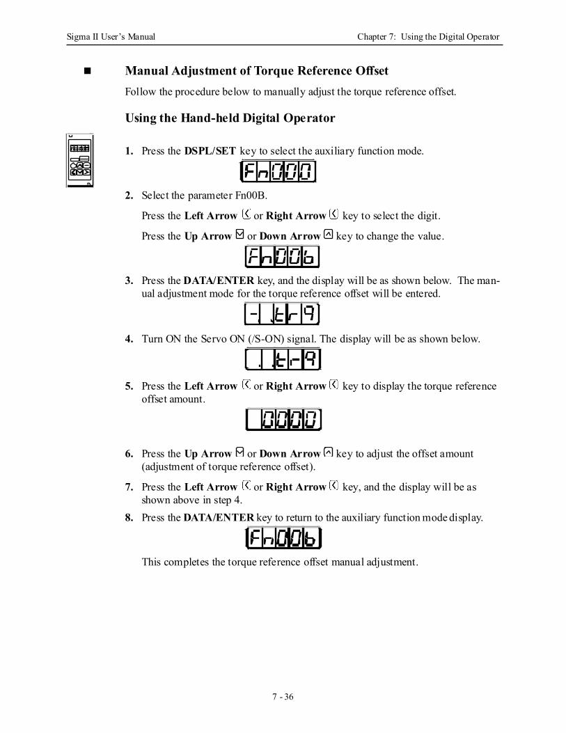
Sigma II User’s Manual Chapter 7: Using the Digital Operator
7 - 36
Manual Adjustment of Torque Reference Offset Follow the procedure below to manually adjust the torque reference offset.
Using the Hand-held Digital Operator
1. Press the DSPL/SET key to select the auxiliary function mode.
2. Select the parameter Fn00B.
Press the Left Arrow or Right Arrow key to select the digit.
Press the Up Arrow or Down Arrow key to change the value.
3. Press the DATA/ENTER key, and the display will be as shown below. The man-ual adjustment mode for the torque reference offset will be entered.
4. Turn ON the Servo ON (/S-ON) signal. The display will be as shown below.
5. Press the Left Arrow or Right Arrow key to display the torque reference offset amount.
6. Press the Up Arrow or Down Arrow key to adjust the offset amount (adjustment of torque reference offset).
7. Press the Left Arrow or Right Arrow key, and the display will be as shown above in step 4.
8. Press the DATA/ENTER key to return to the auxiliary function mode display.
This completes the torque reference offset manual adjustment.
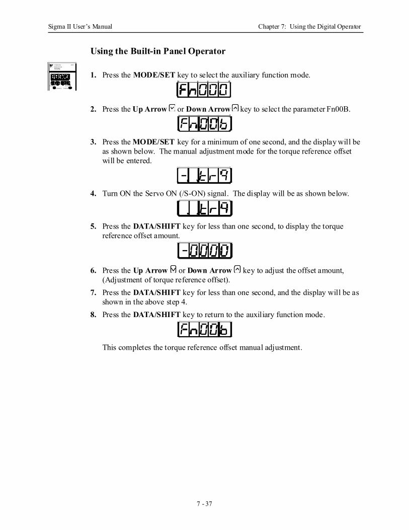
Sigma II User’s Manual Chapter 7: Using the Digital Operator
7 - 37
Using the Built-in Panel Operator
1. Press the MODE/SET key to select the auxiliary function mode.
2. Press the Up Arrow or Down Arrow key to select the parameter Fn00B.
3. Press the MODE/SET key for a minimum of one second, and the display will be as shown below. The manual adjustment mode for the torque reference offset will be entered.
4. Turn ON the Servo ON (/S-ON) signal. The display will be as shown below.
5. Press the DATA/SHIFT key for less than one second, to display the torque reference offset amount.
6. Press the Up Arrow or Down Arrow key to adjust the offset amount, (Adjustment of torque reference offset).
7. Press the DATA/SHIFT key for less than one second, and the display will be as shown in the above step 4.
8. Press the DATA/SHIFT key to return to the auxiliary function mode.
This completes the torque reference offset manual adjustment.
SGDM-
MODE/SET DATA/
CHARGE POWER
SERVOPACK200VYASKAWA
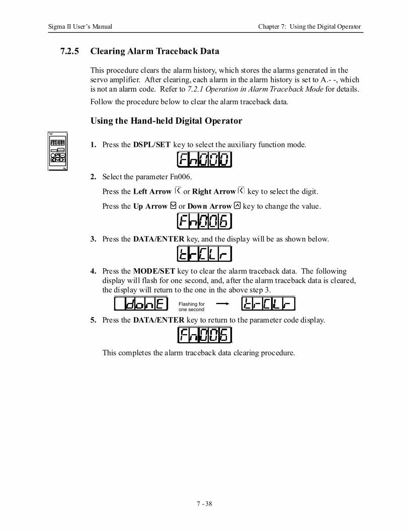
Sigma II User’s Manual Chapter 7: Using the Digital Operator
7 - 38
7.2.5 Clearing Alarm Traceback Data
This procedure clears the alarm history, which stores the alarms generated in the servo amplifier. After clearing, each alarm in the alarm history is set to A.- -, which is not an alarm code. Refer to 7.2.1 Operation in Alarm Traceback Mode for details. Follow the procedure below to clear the alarm traceback data.
Using the Hand-held Digital Operator
1. Press the DSPL/SET key to select the auxiliary function mode.
2. Select the parameter Fn006.
Press the Left Arrow or Right Arrow key to select the digit.
Press the Up Arrow or Down Arrow key to change the value.
3. Press the DATA/ENTER key, and the display will be as shown below.
4. Press the MODE/SET key to clear the alarm traceback data. The following display will flash for one second, and, after the alarm traceback data is cleared, the display will return to the one in the above step 3.
5. Press the DATA/ENTER key to return to the parameter code display.
This completes the alarm traceback data clearing procedure.
Flashing for one second
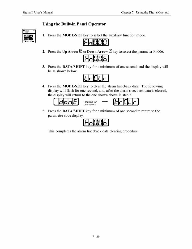
Sigma II User’s Manual Chapter 7: Using the Digital Operator
7 - 39
Using the Built-in Panel Operator
1. Press the MODE/SET key to select the auxiliary function mode.
2. Press the Up Arrow or Down Arrow key to select the parameter Fn006.
3. Press the DATA/SHIFT key for a minimum of one second, and the display will be as shown below.
4. Press the MODE/SET key to clear the alarm traceback data. The following display will flash for one second, and, after the alarm traceback data is cleared, the display will return to the one shown above in step 3.
5. Press the DATA/SHIFT key for a minimum of one second to return to the parameter code display.
This completes the alarm traceback data clearing procedure.
SGDM-
MODE/SET DATA/
CHARGE POWER
SERVOPACK200VYASKAWA
Flashing for one second
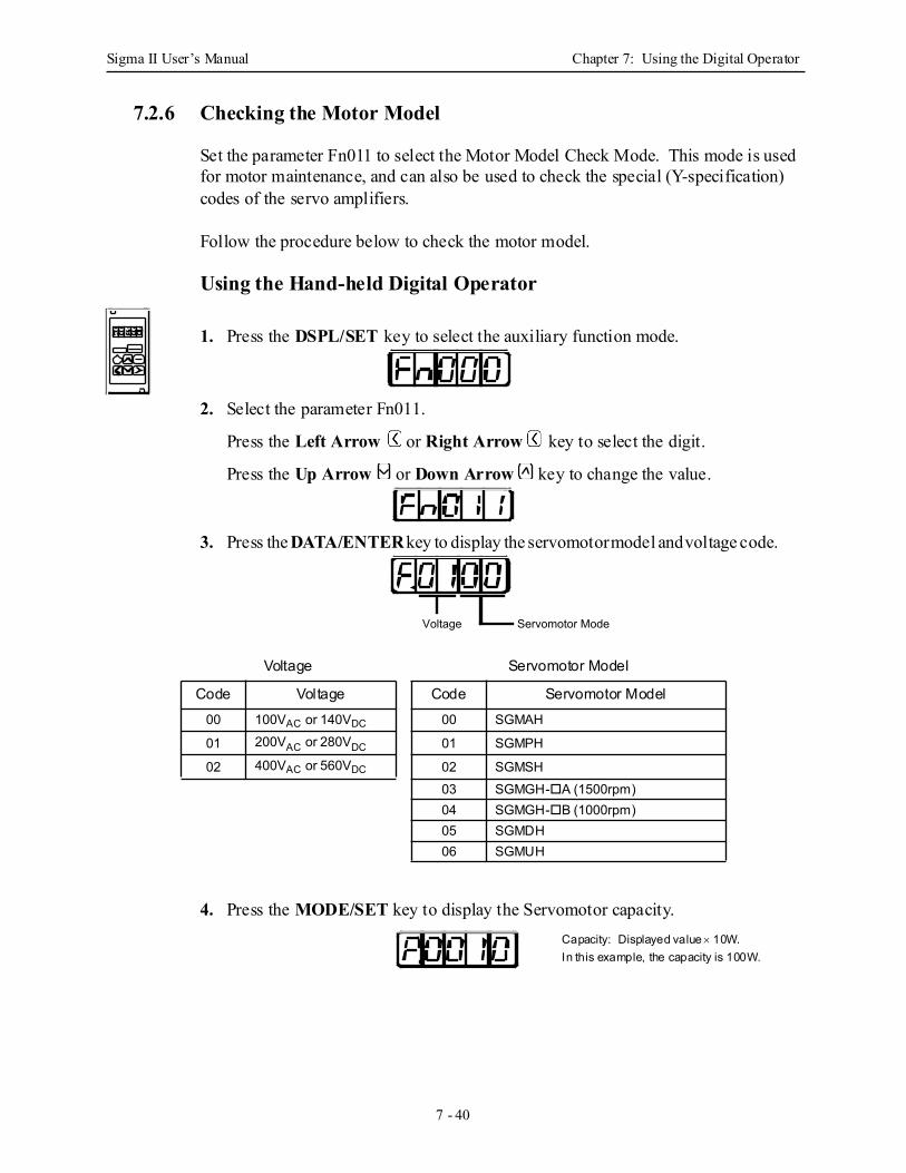
Sigma II User’s Manual Chapter 7: Using the Digital Operator
7 - 40
7.2.6 Checking the Motor Model
Set the parameter Fn011 to select the Motor Model Check Mode. This mode is used for motor maintenance, and can also be used to check the special (Y-specification) codes of the servo amplifiers.
Follow the procedure below to check the motor model.
Using the Hand-held Digital Operator
1. Press the DSPL/SET key to select the auxiliary function mode.
2. Select the parameter Fn011.
Press the Left Arrow or Right Arrow key to select the digit.
Press the Up Arrow or Down Arrow key to change the value.
3. Press the DATA/ENTER key to display the servomotor model and voltage code.
4. Press the MODE/SET key to display the Servomotor capacity.
Voltage Servomotor Model
Code Voltage Code Servomotor Model00 100VAC or 140VDC 00 SGMAH
01 200VAC or 280VDC 01 SGMPH
02 400VAC or 560VDC 02 SGMSH03 SGMGH- A (1500rpm)04 SGMGH- B (1000rpm)05 SGMDH06 SGMUH
Servomotor ModeVoltage
Capacity: Displayed value × 10W.In this example, the capacity is 100W.
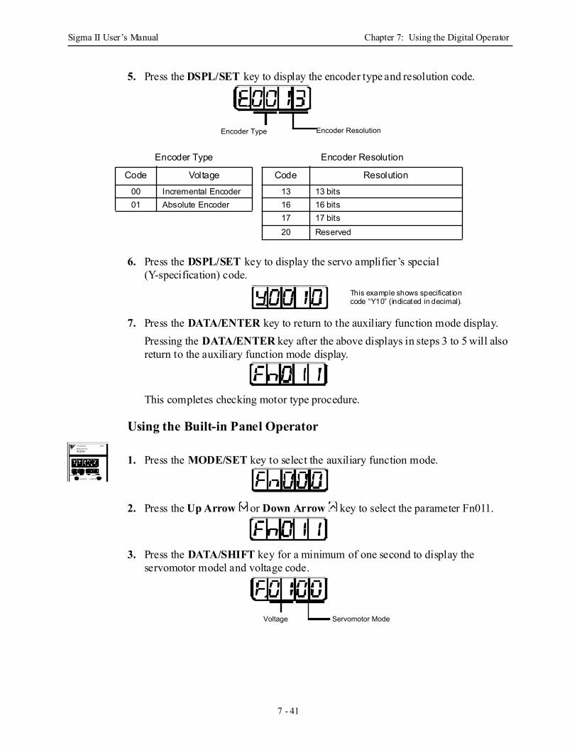
Sigma II User’s Manual Chapter 7: Using the Digital Operator
7 - 41
5. Press the DSPL/SET key to display the encoder type and resolution code.
6. Press the DSPL/SET key to display the servo amplifier’s special (Y-specification) code.
7. Press the DATA/ENTER key to return to the auxiliary function mode display.Pressing the DATA/ENTER key after the above displays in steps 3 to 5 will also return to the auxiliary function mode display.
This completes checking motor type procedure.
Using the Built-in Panel Operator
1. Press the MODE/SET key to select the auxiliary function mode.
2. Press the Up Arrow or Down Arrow key to select the parameter Fn011.
3. Press the DATA/SHIFT key for a minimum of one second to display the servomotor model and voltage code.
Encoder Type Encoder Resolution
Code Voltage Code Resolution00 Incremental Encoder 13 13 bits01 Absolute Encoder 16 16 bits
17 17 bits20 Reserved
Encoder Type Encoder Resolution
This example shows specificat ion code “Y10” (indicated in decimal).
SGDM-
MODE/SET DATA/
CHARGE POWER
SERVOPACK200VYASKAWA
Servomotor ModeVoltage
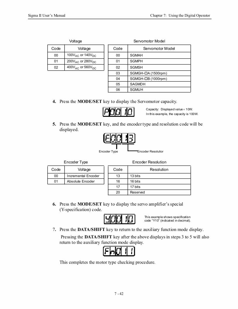
Sigma II User’s Manual Chapter 7: Using the Digital Operator
7 - 42
4. Press the MODE/SET key to display the Servomotor capacity.
5. Press the MODE/SET key, and the encoder type and resolution code will be displayed.
6. Press the MODE/SET key to display the servo amplifier’s special (Y-specification) code.
7. Press the DATA/SHIFT key to return to the auxiliary function mode display. Pressing the DATA/SHIFT key after the above displays in steps 3 to 5 will also return to the auxiliary function mode display.
This completes the motor type checking procedure.
Voltage Servomotor Model
Code Voltage Code Servomotor Model00 100VAC or 140VDC 00 SGMAH01 200VAC or 280VDC 01 SGMPH
02 400VAC or 560VDC 02 SGMSH03 SGMGH- A (1500rpm)04 SGMGH- B (1000rpm)05 SAGMDH06 SGMUH
Encoder Type Encoder Resolution
Code Voltage Code Resolution00 Incremental Encoder 13 13 bits01 Absolute Encoder 16 16 bits
17 17 bits20 Reserved
Capacity: Displayed value × 10W.In this example, the capacity is 100W.
Encoder Type Encoder Resolution
This example shows specificat ion code “Y10” (indicated in decimal).
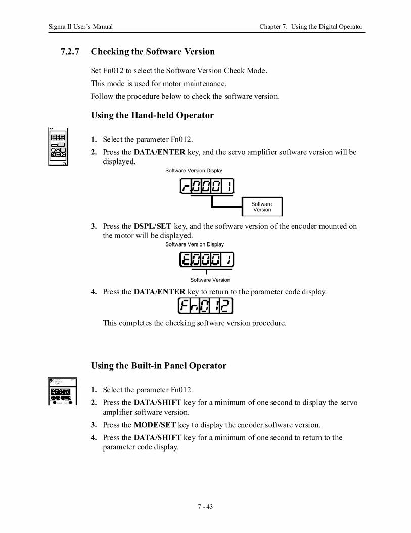
Sigma II User’s Manual Chapter 7: Using the Digital Operator
7 - 43
7.2.7 Checking the Software Version
Set Fn012 to select the Software Version Check Mode. This mode is used for motor maintenance.Follow the procedure below to check the software version.
Using the Hand-held Operator
1. Select the parameter Fn012.2. Press the DATA/ENTER key, and the servo amplifier software version will be
displayed.
3. Press the DSPL/SET key, and the software version of the encoder mounted on the motor will be displayed.
4. Press the DATA/ENTER key to return to the parameter code display.
This completes the checking software version procedure.
Using the Built-in Panel Operator
1. Select the parameter Fn012.2. Press the DATA/SHIFT key for a minimum of one second to display the servo
amplifier software version.3. Press the MODE/SET key to display the encoder software version.4. Press the DATA/SHIFT key for a minimum of one second to return to the
parameter code display.
Software Version Display
Software Version
Software Version Display
Software Version
SGDM-
MODE/SET DATA/
CHARGE POWER
SERVOPACK200VYASKAWA
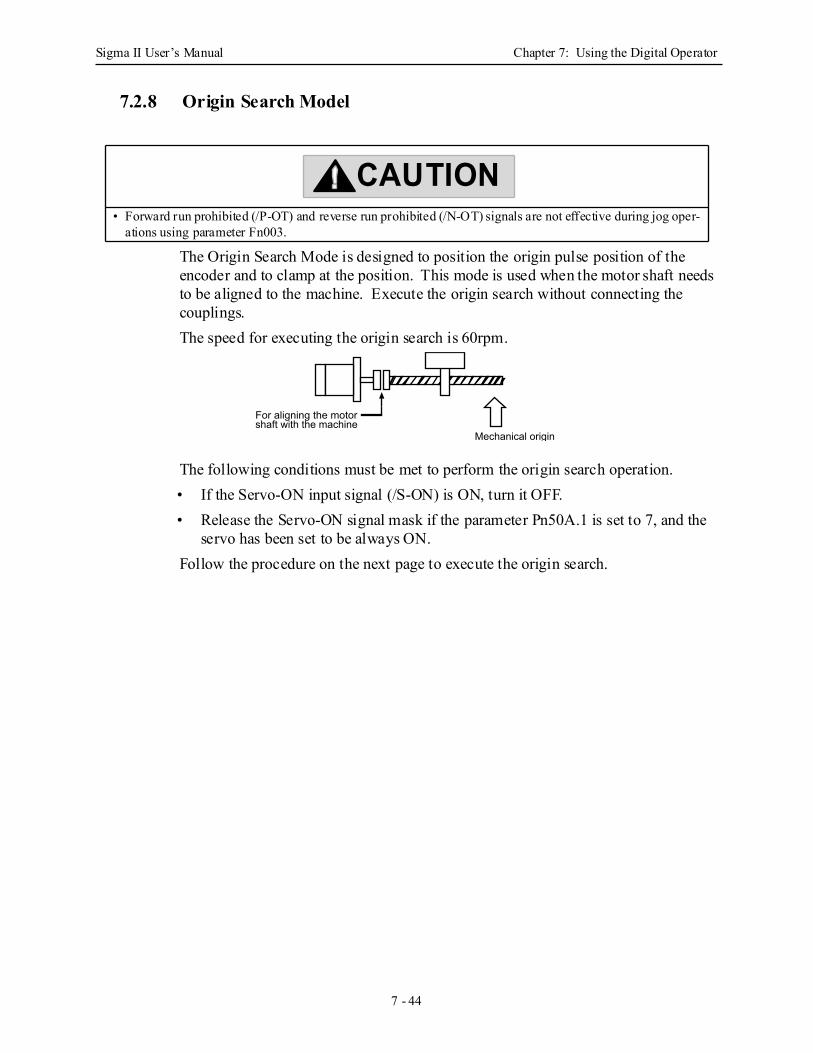
Sigma II User’s Manual Chapter 7: Using the Digital Operator
7 - 44
7.2.8 Origin Search Model
The Origin Search Mode is designed to position the origin pulse position of the encoder and to clamp at the position. This mode is used when the motor shaft needs to be aligned to the machine. Execute the origin search without connecting the couplings.The speed for executing the origin search is 60rpm.
The following conditions must be met to perform the origin search operation.• If the Servo-ON input signal (/S-ON) is ON, turn it OFF.• Release the Servo-ON signal mask if the parameter Pn50A.1 is set to 7, and the
servo has been set to be always ON.Follow the procedure on the next page to execute the origin search.
• Forward run prohibited (/P-OT) and reverse run prohibited (/N-OT) signals are not effective during jog oper-ations using parameter Fn003.
CAUTION
Mechanical origin
For aligning the motor shaft with the machine
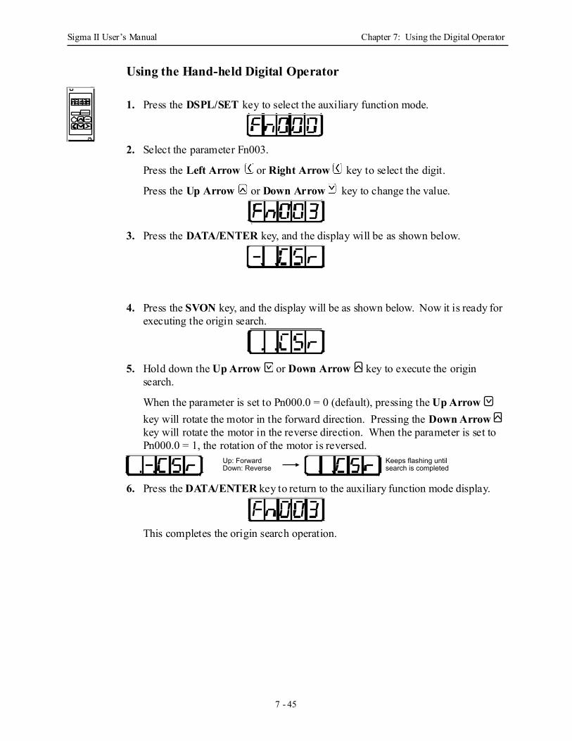
Sigma II User’s Manual Chapter 7: Using the Digital Operator
7 - 45
Using the Hand-held Digital Operator
1. Press the DSPL/SET key to select the auxiliary function mode.
2. Select the parameter Fn003.
Press the Left Arrow or Right Arrow key to select the digit.
Press the Up Arrow or Down Arrow key to change the value.
3. Press the DATA/ENTER key, and the display will be as shown below.
4. Press the SVON key, and the display will be as shown below. Now it is ready for executing the origin search.
5. Hold down the Up Arrow or Down Arrow key to execute the origin search.
When the parameter is set to Pn000.0 = 0 (default), pressing the Up Arrow key will rotate the motor in the forward direction. Pressing the Down Arrow key will rotate the motor in the reverse direction. When the parameter is set to Pn000.0 = 1, the rotation of the motor is reversed.
6. Press the DATA/ENTER key to return to the auxiliary function mode display.
This completes the origin search operation.
Keeps flashing until search is completed
Up: ForwardDown: Reverse
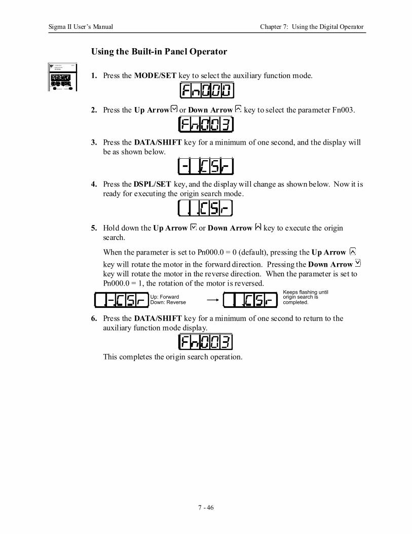
Sigma II User’s Manual Chapter 7: Using the Digital Operator
7 - 46
Using the Built-in Panel Operator
1. Press the MODE/SET key to select the auxiliary function mode.
2. Press the Up Arrow or Down Arrow key to select the parameter Fn003.
3. Press the DATA/SHIFT key for a minimum of one second, and the display will be as shown below.
4. Press the DSPL/SET key, and the display will change as shown below. Now it is ready for executing the origin search mode.
5. Hold down the Up Arrow or Down Arrow key to execute the origin search.
When the parameter is set to Pn000.0 = 0 (default), pressing the Up Arrow key will rotate the motor in the forward direction. Pressing the Down Arrow key will rotate the motor in the reverse direction. When the parameter is set to Pn000.0 = 1, the rotation of the motor is reversed.
6. Press the DATA/SHIFT key for a minimum of one second to return to the auxiliary function mode display.
This completes the origin search operation.
SGDM-
MODE/SET DATA/
CHARGE POWER
SERVOPACK200VYASKAWA
Keeps flashing until origin search is completed.
Up: ForwardDown: Reverse
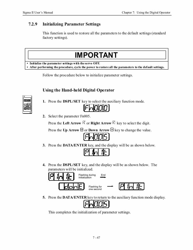
Sigma II User’s Manual Chapter 7: Using the Digital Operator
7 - 47
7.2.9 Initializing Parameter Settings
This function is used to restore all the parameters to the default settings (standard factory settings).
Follow the procedure below to initialize parameter settings.
Using the Hand-held Digital Operator
1. Press the DSPL/SET key to select the auxiliary function mode.
2. Select the parameter Fn005.
Press the Left Arrow or Right Arrow key to select the digit.
Press the Up Arrow or Down Arrow key to change the value.
3. Press the DATA/ENTER key, and the display will be as shown below.
4. Press the DSPL/SET key, and the display will be as shown below. The parameters will be initialized.
5. Press the DATA/ENTER key to return to the auxiliary function mode display.
This completes the initialization of parameter settings.
• Initialize the parameter settings with the servo OFF.• After performing the procedure, cycle the power to restore all the parameters to the default settings.
IMPORTANT
Flashing for one second
Flashing during initialization
End
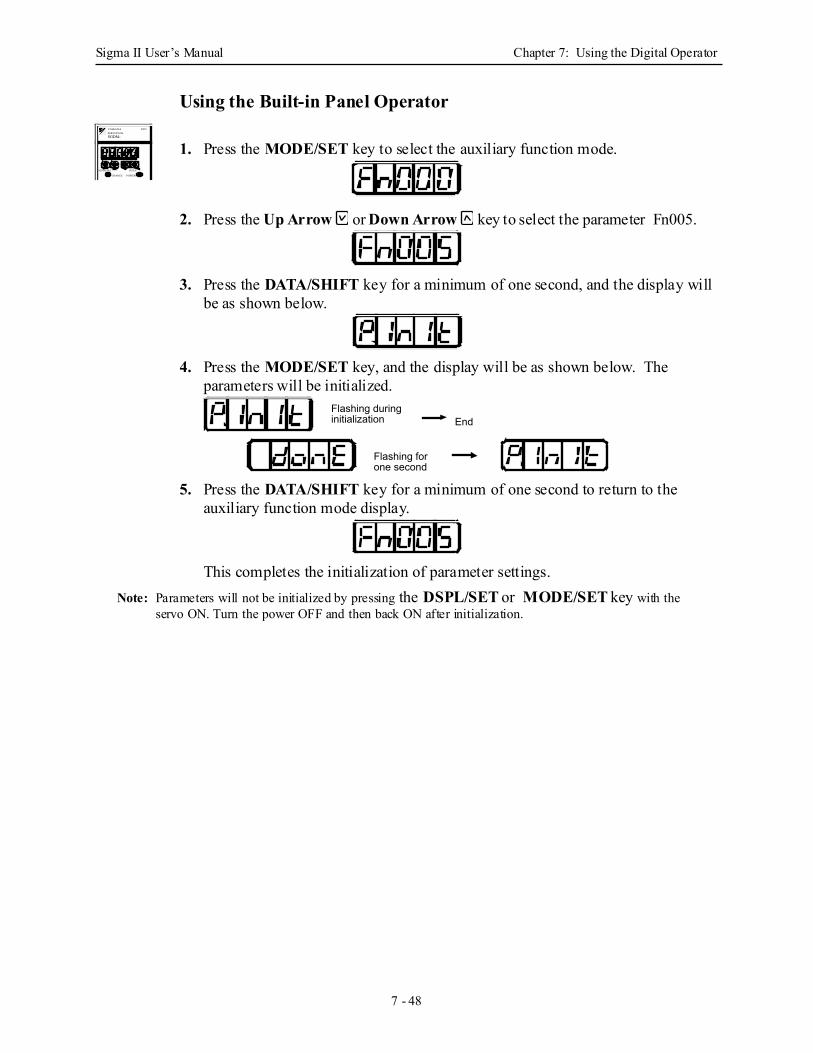
Sigma II User’s Manual Chapter 7: Using the Digital Operator
7 - 48
Using the Built-in Panel Operator
1. Press the MODE/SET key to select the auxiliary function mode.
2. Press the Up Arrow or Down Arrow key to select the parameter Fn005.
3. Press the DATA/SHIFT key for a minimum of one second, and the display will be as shown below.
4. Press the MODE/SET key, and the display will be as shown below. The parameters will be initialized.
5. Press the DATA/SHIFT key for a minimum of one second to return to the auxiliary function mode display.
This completes the initialization of parameter settings.Note: Parameters will not be initialized by pressing the DSPL/SET or MODE/SET key with the
servo ON. Turn the power OFF and then back ON after initialization.
SGDM-
MODE/SET DATA/
CHARGE POWER
SERVOPACK200VYASKAWA
Flashing for one second
Flashing during initialization End
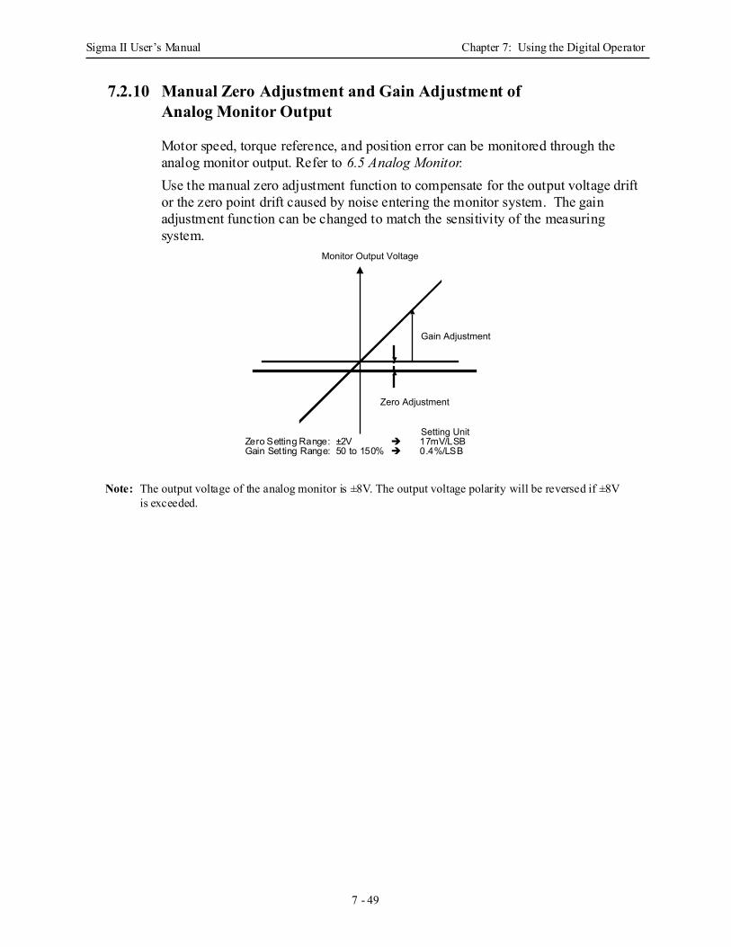
Sigma II User’s Manual Chapter 7: Using the Digital Operator
7 - 49
7.2.10 Manual Zero Adjustment and Gain Adjustment ofAnalog Monitor Output
Motor speed, torque reference, and position error can be monitored through the analog monitor output. Refer to 6.5 Analog Monitor.Use the manual zero adjustment function to compensate for the output voltage drift or the zero point drift caused by noise entering the monitor system. The gain adjustment function can be changed to match the sensitivity of the measuring system.
Note: The output voltage of the analog monitor is ±8V. The output voltage polarity will be reversed if ±8V is exceeded.
Monitor Output Voltage
Zero Adjustment
Gain Adjustment
Setting UnitZero Setting Range: ±2V 17mV/LSBGain Setting Range: 50 to 150% 0.4%/LSB
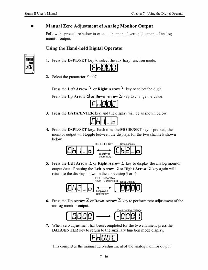
Sigma II User’s Manual Chapter 7: Using the Digital Operator
7 - 50
Manual Zero Adjustment of Analog Monitor OutputFollow the procedure below to execute the manual zero adjustment of analog monitor output.
Using the Hand-held Digital Operator
1. Press the DSPL/SET key to select the auxiliary function mode.
2. Select the parameter Fn00C.
Press the Left Arrow or Right Arrow key to select the digit.
Press the Up Arrow or Down Arrow key to change the value.
3. Press the DATA/ENTER key, and the display will be as shown below.
4. Press the DSPL/SET key. Each time the MODE/SET key is pressed, the monitor output will toggle between the displays for the two channels shown below.
5. Press the Left Arrow or Right Arrow key to display the analog monitor output data. Pressing the Left Arrow or Right Arrow key again will return to the display shown in the above step 3 or 4.
6. Press the Up Arrow or Down Arrow key to perform zero adjustment of the analog monitor output.
7. When zero adjustment has been completed for the two channels, press the DATA/ENTER key to return to the auxiliary function mode display.
This completes the manual zero adjustment of the analog monitor output.
DSPL/SET Key
Displayed alternately
Data Display
Displayed alternately
LEFT Cursor Key(RIGHT Cursor Key) Data Display
Data Setting Change
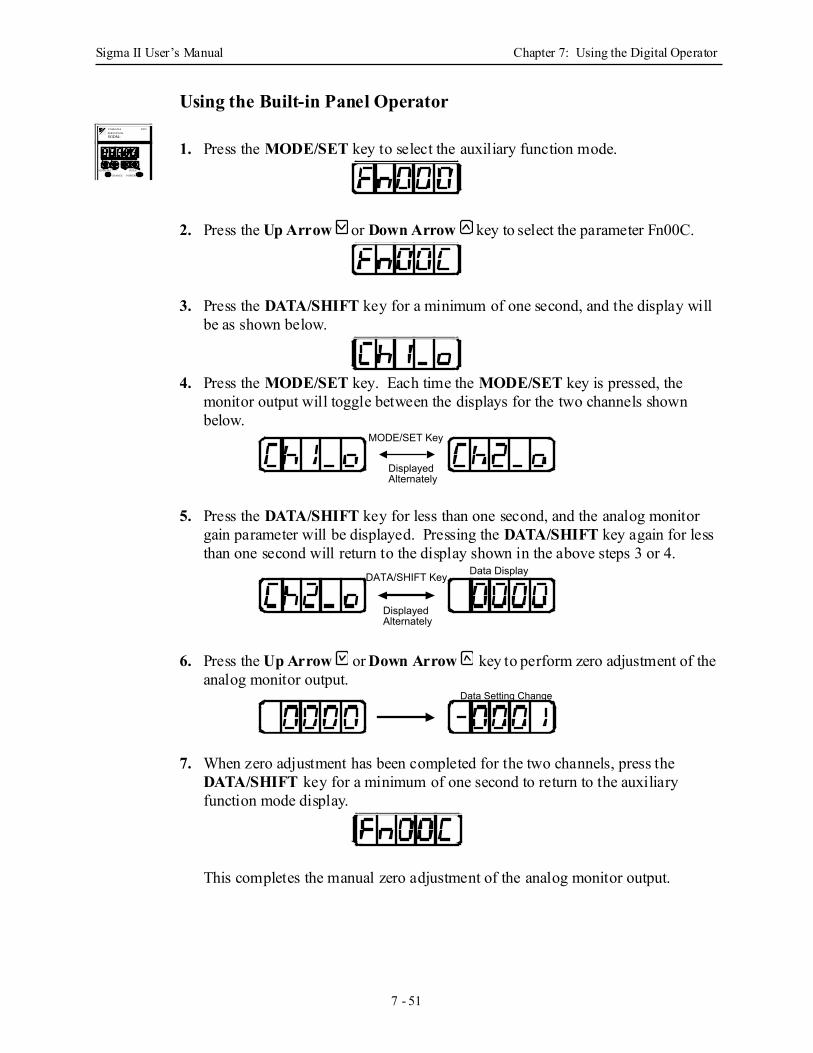
Sigma II User’s Manual Chapter 7: Using the Digital Operator
7 - 51
Using the Built-in Panel Operator
1. Press the MODE/SET key to select the auxiliary function mode.
2. Press the Up Arrow or Down Arrow key to select the parameter Fn00C.
3. Press the DATA/SHIFT key for a minimum of one second, and the display will be as shown below.
4. Press the MODE/SET key. Each time the MODE/SET key is pressed, the monitor output will toggle between the displays for the two channels shown below.
5. Press the DATA/SHIFT key for less than one second, and the analog monitor gain parameter will be displayed. Pressing the DATA/SHIFT key again for less than one second will return to the display shown in the above steps 3 or 4.
6. Press the Up Arrow or Down Arrow key to perform zero adjustment of the analog monitor output.
7. When zero adjustment has been completed for the two channels, press the DATA/SHIFT key for a minimum of one second to return to the auxiliary function mode display.
This completes the manual zero adjustment of the analog monitor output.
SGDM-
MODE/SET DATA/
CHARGE POWER
SERVOPACK200VYASKAWA
MODE/SET Key
Displayed Alternately
Data DisplayDATA/SHIFT Key
Displayed Alternately
Data Setting Change
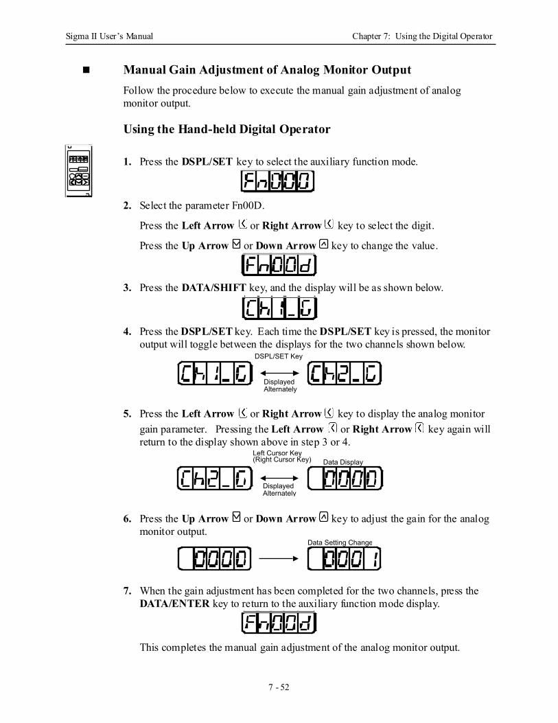
Sigma II User’s Manual Chapter 7: Using the Digital Operator
7 - 52
Manual Gain Adjustment of Analog Monitor Output Follow the procedure below to execute the manual gain adjustment of analog monitor output.
Using the Hand-held Digital Operator
1. Press the DSPL/SET key to select the auxiliary function mode.
2. Select the parameter Fn00D.
Press the Left Arrow or Right Arrow key to select the digit.
Press the Up Arrow or Down Arrow key to change the value.
3. Press the DATA/SHIFT key, and the display will be as shown below.
4. Press the DSPL/SET key. Each time the DSPL/SET key is pressed, the monitor output will toggle between the displays for the two channels shown below.
5. Press the Left Arrow or Right Arrow key to display the analog monitor gain parameter. Pressing the Left Arrow or Right Arrow key again will return to the display shown above in step 3 or 4.
6. Press the Up Arrow or Down Arrow key to adjust the gain for the analog monitor output.
7. When the gain adjustment has been completed for the two channels, press the DATA/ENTER key to return to the auxiliary function mode display.
This completes the manual gain adjustment of the analog monitor output.
DSPL/SET Key
Displayed Alternately
Left Cursor Key(Right Cursor Key) Data Display
Displayed Alternately
Data Setting Change
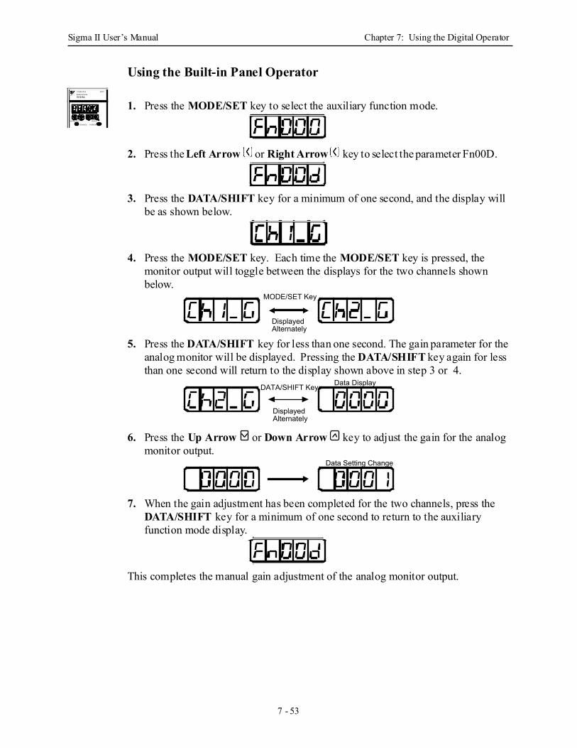
Sigma II User’s Manual Chapter 7: Using the Digital Operator
7 - 53
Using the Built-in Panel Operator
1. Press the MODE/SET key to select the auxiliary function mode.
2. Press the Left Arrow or Right Arrow key to select the parameter Fn00D.
3. Press the DATA/SHIFT key for a minimum of one second, and the display will be as shown below.
4. Press the MODE/SET key. Each time the MODE/SET key is pressed, the monitor output will toggle between the displays for the two channels shown below.
5. Press the DATA/SHIFT key for less than one second. The gain parameter for the analog monitor will be displayed. Pressing the DATA/SHIFT key again for less than one second will return to the display shown above in step 3 or 4.
6. Press the Up Arrow or Down Arrow key to adjust the gain for the analog monitor output.
7. When the gain adjustment has been completed for the two channels, press the DATA/SHIFT key for a minimum of one second to return to the auxiliary function mode display.
This completes the manual gain adjustment of the analog monitor output.
SGDM-
MODE/SET DATA/
CHARGE POWER
SERVOPACK200VYASKAWA
MODE/SET Key
Displayed Alternately
Data DisplayDATA/SHIFT Key
Displayed Alternately
Data Setting Change
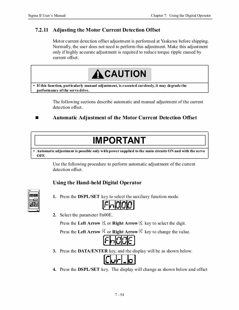
Sigma II User’s Manual Chapter 7: Using the Digital Operator
7 - 54
7.2.11 Adjusting the Motor Current Detection Offset
Motor current detection offset adjustment is performed at Yaskawa before shipping. Normally, the user does not need to perform this adjustment. Make this adjustment only if highly accurate adjustment is required to reduce torque ripple caused by current offset.
The following sections describe automatic and manual adjustment of the current detection offset.
Automatic Adjustment of the Motor Current Detection Offset
Use the following procedure to perform automatic adjustment of the current detection offset.
Using the Hand-held Digital Operator
1. Press the DSPL/SET key to select the auxiliary function mode.
2. Select the parameter Fn00E.
Press the Left Arrow or Right Arrow key to select the digit.
Press the Left Arrow or Right Arrow key to change the value.
3. Press the DATA/ENTER key, and the display will be as shown below.
4. Press the DSPL/SET key. The display will change as shown below and offset
• If this function, particularly manual adjustment, is executed carelessly, it may degrade the performance of the servo drive.
• Automatic adjustment is possible only with power supplied to the main circuits ON and with the servo OFF.
CAUTION
IMPORTANT
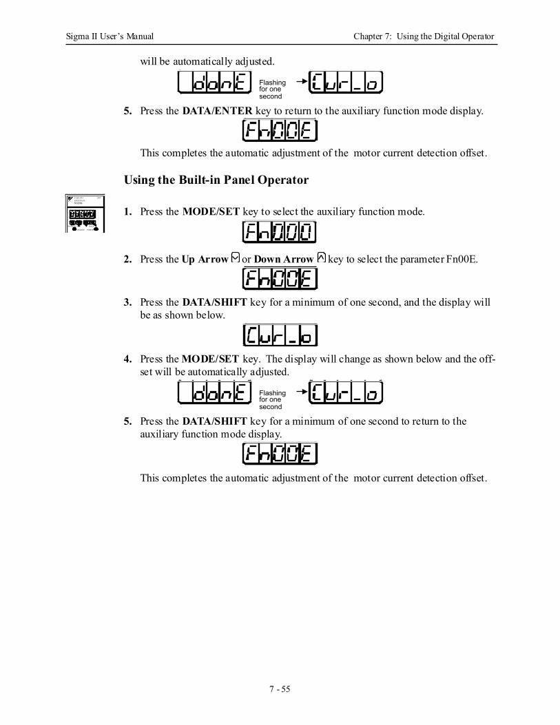
Sigma II User’s Manual Chapter 7: Using the Digital Operator
7 - 55
will be automatically adjusted.
5. Press the DATA/ENTER key to return to the auxiliary function mode display.
This completes the automatic adjustment of the motor current detection offset.
Using the Built-in Panel Operator
1. Press the MODE/SET key to select the auxiliary function mode.
2. Press the Up Arrow or Down Arrow key to select the parameter Fn00E.
3. Press the DATA/SHIFT key for a minimum of one second, and the display will be as shown below.
4. Press the MODE/SET key. The display will change as shown below and the off-set will be automatically adjusted.
5. Press the DATA/SHIFT key for a minimum of one second to return to the auxiliary function mode display.
This completes the automatic adjustment of the motor current detection offset.
Flashing for one second
SGDM-
MODE/SET DATA/
CHARGE POWER
SERVOPACK200VYASKAWA
Flashing for one second
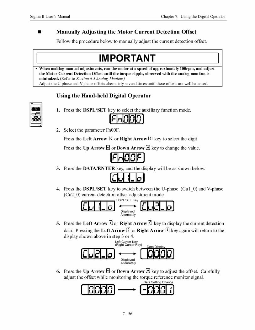
Sigma II User’s Manual Chapter 7: Using the Digital Operator
7 - 56
Manually Adjusting the Motor Current Detection Offset Follow the procedure below to manually adjust the current detection offset.
Using the Hand-held Digital Operator
1. Press the DSPL/SET key to select the auxiliary function mode.
2. Select the parameter Fn00F.
Press the Left Arrow or Right Arrow key to select the digit.
Press the Up Arrow or Down Arrow key to change the value.
3. Press the DATA/ENTER key, and the display will be as shown below.
4. Press the DSPL/SET key to switch between the U-phase (Cu1_0) and V-phase (Cu2_0) current detection offset adjustment mode
5. Press the Left Arrow or Right Arrow key to display the current detection data. Pressing the Left Arrow or Right Arrow key again will return to the display shown above in step 3 or 4.
6. Press the Up Arrow or Down Arrow key to adjust the offset. Carefully adjust the offset while monitoring the torque reference monitor signal.
• When making manual adjustments, run the motor at a speed of approximately 100rpm, and adjust the Motor Current Detection Offset until the torque ripple, observed with the analog monitor, is minimized. (Refer to Section 6.5 Analog Monitor.)Adjust the U-phase and V-phase offsets alternately several times until these offsets are well balanced.
IMPORTANT
DSPL/SET Key
Displayed Alternately
Data DisplayLeft Cursor Key(Right Cursor Key)
Displayed Alternately
Data Setting Change
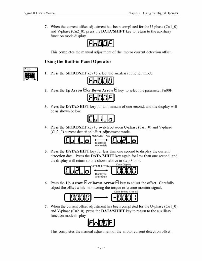
Sigma II User’s Manual Chapter 7: Using the Digital Operator
7 - 57
7. When the current offset adjustment has been completed for the U-phase (Cu1_0) and V-phase (Cu2_0), press the DATA/SHIFT key to return to the auxiliary function mode display.
This completes the manual adjustment of the motor current detection offset.
Using the Built-in Panel Operator
1. Press the MODE/SET key to select the auxiliary function mode.
2. Press the Up Arrow or Down Arrow key to select the parameter Fn00F.
3. Press the DATA/SHIFT key for a minimum of one second, and the display will be as shown below.
4. Press the MODE/SET key to switch between U-phase (Cu1_0) and V-phase (Cu2_0) current detection offset adjustment mode.
5. Press the DATA/SHIFT key for less than one second to display the current detection data. Press the DATA/SHIFT key again for less than one second, and the display will return to one shown above in step 3 or 4.
6. Press the Up Arrow or Down Arrow key to adjust the offset. Carefully adjust the offset while monitoring the torque reference monitor signal.
7. When the current offset adjustment has been completed for the U-phase (Cu1_0) and V-phase (Cu2_0), press the DATA/SHIFT key to return to the auxiliary function mode display
This completes the manual adjustment of the motor current detection offset.
SGDM-
MODE/SET DATA/
CHARGE POWER
SERVOPACK200VYASKAWA
MODE/SET Key
Displayed Alternately
Data DisplayDATA/SHIFT Key
Displayed Alternately
Data Setting Change
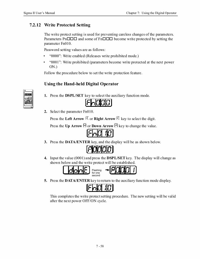
Sigma II User’s Manual Chapter 7: Using the Digital Operator
7 - 58
7.2.12 Write Protected Setting
The write protect setting is used for preventing careless changes of the parameters. Parameters Pn and some of Fn become write protected by setting the parameter Fn010.Password setting values are as follows:• “0000”: Write enabled (Releases write prohibited mode.)• “0001”: Write prohibited (parameters become write protected at the next power
ON.)Follow the procedure below to set the write protection feature.
Using the Hand-held Digital Operator
1. Press the DSPL/SET key to select the auxiliary function mode.
2. Select the parameter Fn010.
Press the Left Arrow or Right Arrow key to select the digit.
Press the Up Arrow or Down Arrow key to change the value.
3. Press the DATA/ENTER key, and the display will be as shown below.
4. Input the value (0001) and press the DSPL/SET key. The display will change as shown below and the write protect will be established.
5. Press the DATA/ENTER key to return to the auxiliary function mode display.
This completes the write protect setting procedure. The new setting will be valid after the next power OFF/ON cycle.
Flashing for one second
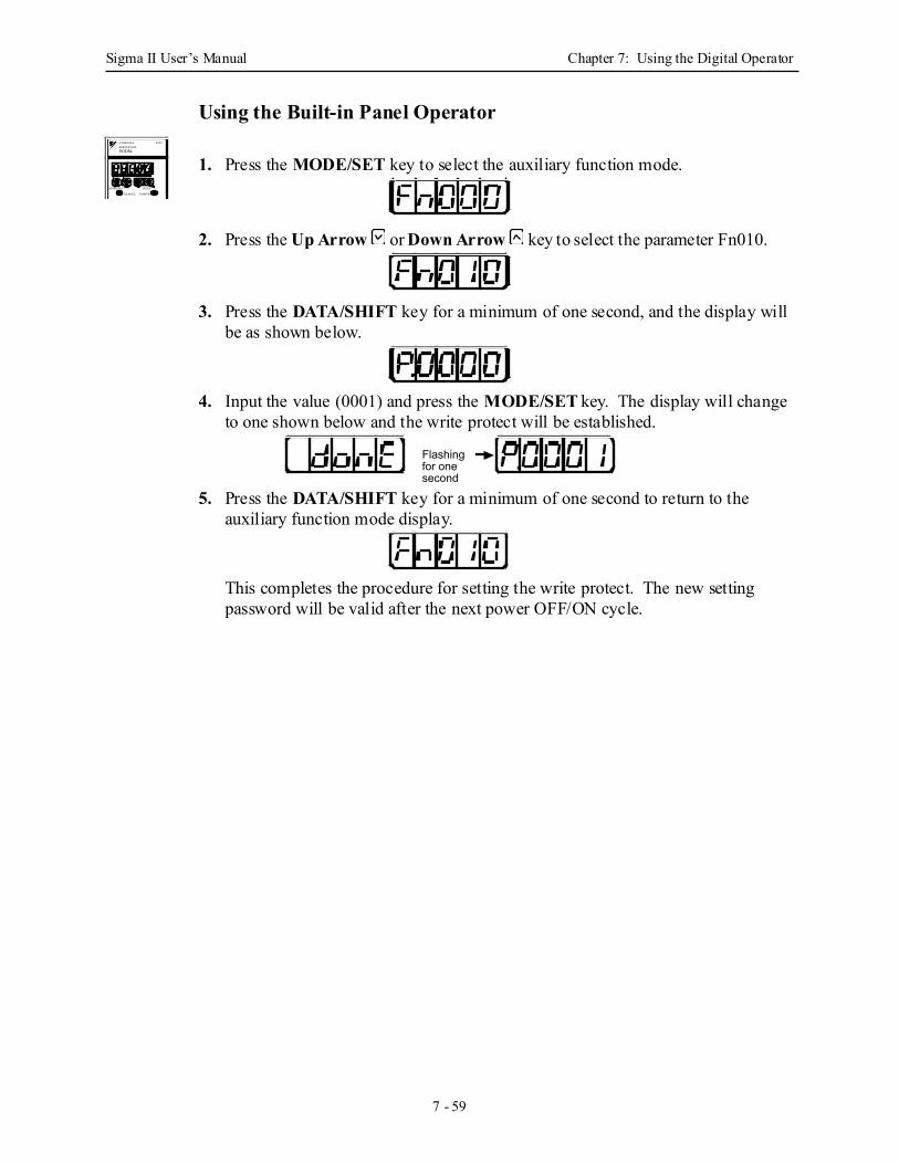
Sigma II User’s Manual Chapter 7: Using the Digital Operator
7 - 59
Using the Built-in Panel Operator
1. Press the MODE/SET key to select the auxiliary function mode.
2. Press the Up Arrow or Down Arrow key to select the parameter Fn010.
3. Press the DATA/SHIFT key for a minimum of one second, and the display will be as shown below.
4. Input the value (0001) and press the MODE/SET key. The display will change to one shown below and the write protect will be established.
5. Press the DATA/SHIFT key for a minimum of one second to return to the auxiliary function mode display.
This completes the procedure for setting the write protect. The new setting password will be valid after the next power OFF/ON cycle.
SGDM-
MODE/SET DATA/
CHARGE POWER
SERVOPACK200VYASKAWA
Flashing for one second
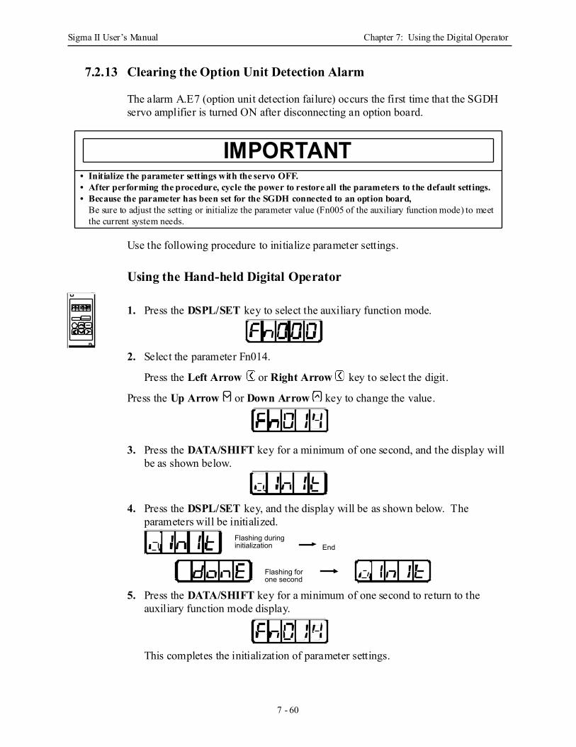
Sigma II User’s Manual Chapter 7: Using the Digital Operator
7 - 60
7.2.13 Clearing the Option Unit Detection Alarm
The alarm A.E7 (option unit detection failure) occurs the first time that the SGDH servo amplifier is turned ON after disconnecting an option board.
Use the following procedure to initialize parameter settings.
Using the Hand-held Digital Operator
1. Press the DSPL/SET key to select the auxiliary function mode.
2. Select the parameter Fn014.
Press the Left Arrow or Right Arrow key to select the digit.
Press the Up Arrow or Down Arrow key to change the value.
3. Press the DATA/SHIFT key for a minimum of one second, and the display will be as shown below.
4. Press the DSPL/SET key, and the display will be as shown below. The parameters will be initialized.
5. Press the DATA/SHIFT key for a minimum of one second to return to the auxiliary function mode display.
This completes the initialization of parameter settings.
• Initialize the parameter settings with the servo OFF.• After performing the procedure, cycle the power to restore all the parameters to the default settings.• Because the parameter has been set for the SGDH connected to an option board,
Be sure to adjust the setting or initialize the parameter value (Fn005 of the auxiliary function mode) to meet the current system needs.
IMPORTANT
Flashing for one second
Flashing during initialization End
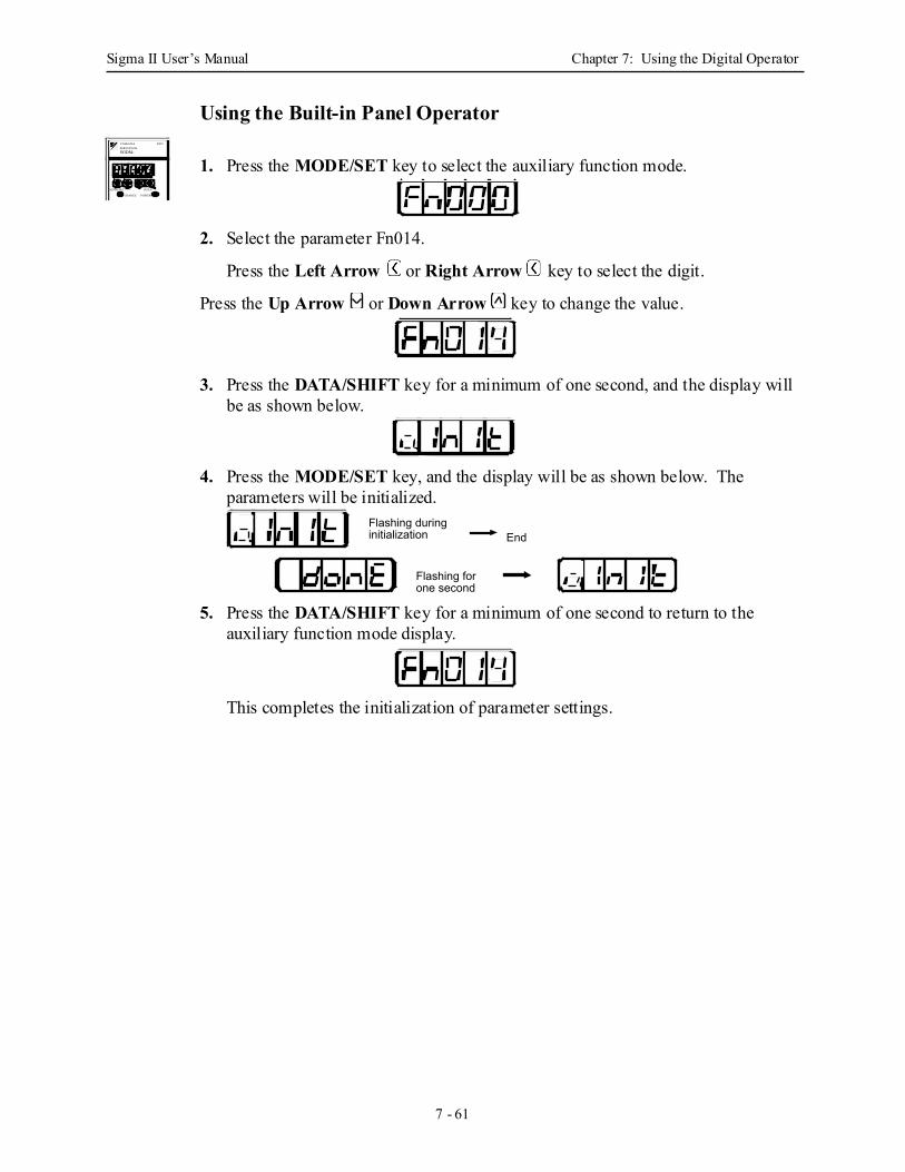
Sigma II User’s Manual Chapter 7: Using the Digital Operator
7 - 61
Using the Built-in Panel Operator
1. Press the MODE/SET key to select the auxiliary function mode.
2. Select the parameter Fn014.
Press the Left Arrow or Right Arrow key to select the digit.
Press the Up Arrow or Down Arrow key to change the value.
3. Press the DATA/SHIFT key for a minimum of one second, and the display will be as shown below.
4. Press the MODE/SET key, and the display will be as shown below. The parameters will be initialized.
5. Press the DATA/SHIFT key for a minimum of one second to return to the auxiliary function mode display.
This completes the initialization of parameter settings.
SGDM-
MODE/SET DATA/
CHARGE POWER
SERVOPACK200VYASKAWA
Flashing for one second
Flashing during initialization End

Sigma II User’s Manual Chapter 7: Using the Digital Operator
7 - 62
Notes
Sigma II User’s Manual Chapter 8: Ratings and Characteristics
8 - 1
8 Ratings and CharacteristicsThis chapter provides the ratings, torque-speed characteristics diagrams, and dimensional drawings of the Sigma II series servo drives.
8.1 Servomotors: Ratings, Specifications, and Dimensional Drawings .................... 8-2
8.1.1 SGMAH Servomotors................................................................................. 8-2
8.1.2 SGMPH Servomotors ................................................................................. 8-7
8.1.3 SGMGH Servomotors for 1500rpm ......................................................... 8-11
8.1.4 SGMSH Servomotors ............................................................................... 8-15
8.1.5 SGMUH Servomotors............................................................................... 8-19
8.1.6 SGMBH Servomotors ............................................................................... 8-22
8.2 Servo Amplifiers ................................................................................................ 8-28
8.2.1 Combined Specifications .......................................................................... 8-28
8.2.2 Ratings and Specifications ........................................................................ 8-34
8.2.3 Base-Mounted Servo Amplifier Dimensions in inches (mm) .................. 8-43
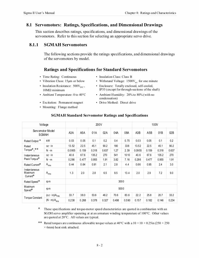
Sigma II User’s Manual Chapter 8: Ratings and Characteristics
8 - 2
8.1 Servomotors: Ratings, Specifications, and Dimensional DrawingsThis section describes ratings, specifications, and dimensional drawings of the servomotors. Refer to this section for selecting an appropriate servo drive.
8.1.1 SGMAH Servomotors
The following sections provide the ratings specifications, and dimensional drawings of the servomotors by model.
Ratings and Specifications for Standard Servomotors
SGMAH Standard Servomotor Ratings and Specifications
* These specifications and torque-motor speed characteristics are quoted in combination with an SGDH servo amplifier operating at at an armature winding temperature of 100°C. Other values are quoted at 20°C. All values are typical.
** Rated torques are continuous allowable torque values at 40°C with a 10 × 10 × 0.25in (250 × 250 × 6mm) heat sink attached.
• Time Rating: Continuous • Insulation Class: Class B• Vibration Class: 15µm or below • Withstand Voltage: 1500Va c for one minute• Insulation Resistance: 500VD C ,
10MΩ minimum• Enclosure: Totally enclosed, self-cooled,
IP55 (except for through-sections of the shaft)• Ambient Temperature: 0 to 40°C • Ambient Humidity: 20% to 80% (with no
condensation)• Excitation: Permanent magnet • Drive Method: Direct drive• Mounting: Flange method
Voltage 200V 100V
Servomotor ModelSGMAH A3A A5A 01A 02A 04A 08A A3B A5B 01B 02B
Rated Output * kW 0.03 0.05 0.1 0.2 0.4 0.75 0.03 0.05 0.1 0.2
Rated Torque*,**
oz · in 13 .52 22.5 45.1 90.2 180 338 13.52 22.5 45.1 90.2N · m 0.0955 0.159 0.318 0.637 1.27 2.39 0.0955 0.159 0.318 0.637
Instan taneous Peak Torque*
oz · in 40 .6 67.6 135.2 270 541 1010 40.6 67.6 135.2 270N · m 0.286 0.477 0.955 1.91 3.82 7.16 0.286 0.477 0.955 1.91
Rated Current* Arms 0.44 0.64 0.91 2.1 2.8 4 .4 0.66 0.95 2.4 3.0
Instan taneousMaximum Current*
Arms 1 .3 2.0 2.8 6.5 8.5 13.4 2.0 2.9 7.2 9.0
Rated Speed* rpm 3000
Maximum Speed* rpm 5000
Torque Constant(oz · in)/Arms 33 .7 38.0 53.6 46.2 70.6 83.6 22.2 25.8 20.7 33.2(N · m)/Arms 0.238 0.268 0.378 0.327 0.498 0.590 0.157 0.182 0.146 0.234
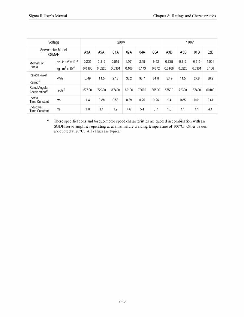
Sigma II User’s Manual Chapter 8: Ratings and Characteristics
8 - 3
* These specifications and torque-motor speed characteristics are quoted in combination with an SGDH servo amplifier operating at at an armature winding temperature of 100°C. Other values are quoted at 20°C. All values are typical.
Voltage 200V 100V
Servomotor ModelSGMAH A3A A5A 01A 02A 04A 08A A3B A5B 01B 02B
Moment of Inertia
oz · in · s2 x 10 -3 0.235 0.312 0.515 1.501 2.45 9.52 0.235 0.312 0.515 1.501
kg · m2 x 10-4 0.0166 0.0220 0.0364 0.106 0.173 0.672 0.0166 0.0220 0.0364 0.106
Rated Power
Rating*kW/s 5.49 11.5 27.8 38.2 93.7 84.8 5.49 11.5 27.8 38.2
Rated Angular Accele ration* rad/s2 57500 72300 87400 60100 73600 35500 57500 72300 87400 60100
InertiaTime Constant ms 1.4 0 .88 0.53 0.39 0.25 0.26 1.4 0.85 0.61 0.41
Induct iveTime Constant ms 1.0 1.1 1.2 4.6 5.4 8 .7 1.0 1.1 1.1 4.4
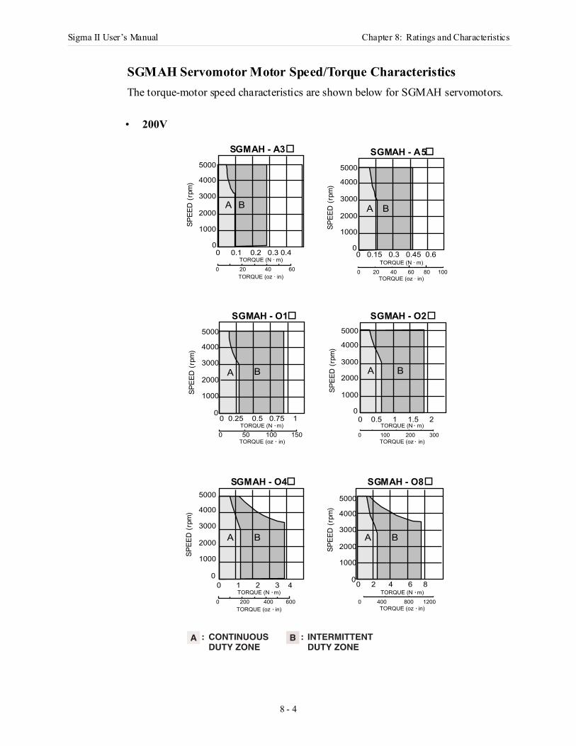
Sigma II User’s Manual Chapter 8: Ratings and Characteristics
8 - 4
SGMAH Servomotor Motor Speed/Torque Characteristics The torque-motor speed characteristics are shown below for SGMAH servomotors.
• 200V
BA
SPEE
D (r
pm) 4000
3000
2000
1000
5000
0
BA
SPEE
D (r
pm)
4000
3000
2000
1000
5000
00 1 2 3 4
0 200 400 600
TORQUE (N · m)
TORQUE (oz · in)
0 2 4 6 8
0 400 800 1200
TORQUE (N · m)
TORQUE (oz · in)
BA
SPEE
D (r
pm) 4000
3000
2000
1000
5000
00 0.5 1 1.5 2
0 100 200 300
TORQUE (N · m)
TORQUE (oz · in)
SPEE
D (r
pm) 4000
3000
2000
1000
5000
0
BA
0 50 100 150TORQUE (N · m)
TORQUE (oz · in)
0 0.25 0.5 0.75 1
SPEE
D (r
pm) 4000
3000
2000
1000
5000
0
BA
0 0.15 0.3 0.45 0.6
0 20 40 60 80 100
TORQUE (N · m)
TORQUE (oz · in)
BA
SPEE
D (r
pm) 4000
3000
2000
1000
5000
00 0.1 0.2 0.3 0.4
0 20 40 60
TORQUE (N · m)
TORQUE (oz · in)
CONTINUOUSDUTY ZONE
INTERMITTENTDUTY ZONE
A : B :
SGMAH - A3 SGMAH - A5
SGMAH - O1 SGMAH - O2
SGMAH - O4 SGMAH - O8
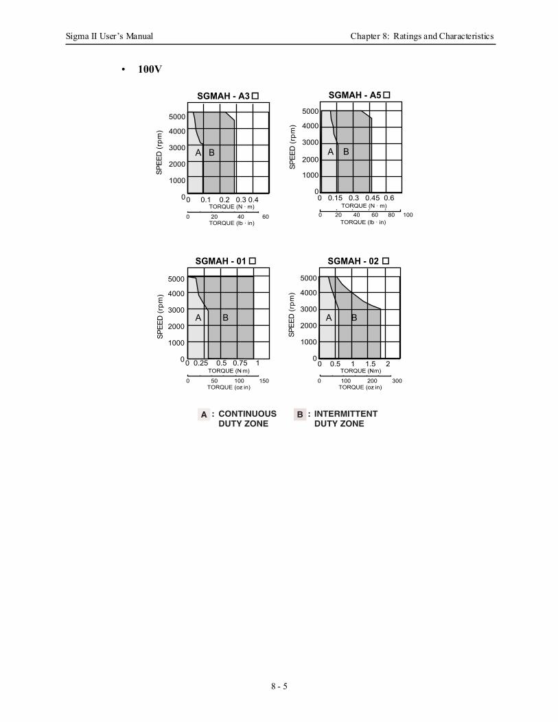
Sigma II User’s Manual Chapter 8: Ratings and Characteristics
8 - 5
• 100V
0 0.25 0.5 0.75 1
BA
SGMAH - 02
SPEE
D (r
pm) 4000
3000
2000
1000
5000
00 0.5 1 1.5 2
0 100 200 300
TORQUE (N · m)
TORQUE (oz · in)0 50 100 150
TORQUE (oz · in)
TORQUE (N · m)
SGMAH - 01
SPEE
D (r
pm) 4000
3000
2000
1000
5000
0
BA
SGMAH - A3
BA
0 0.1 0.2 0.3 0.4
0 20 40 60
TORQUE (N · m)
TORQUE (lb · in)
SPEE
D (r
pm) 4000
3000
2000
1000
5000
0
SGMAH - A5
BA
0 0.15 0.3 0.45 0.6
0 20 40 60 80 100TORQUE (N · m)
TORQUE (lb · in)
SPEE
D (r
pm) 4000
3000
2000
1000
5000
0
CONTINUOUSDUTY ZONE
INTERMITTENTDUTY ZONE
A : B :
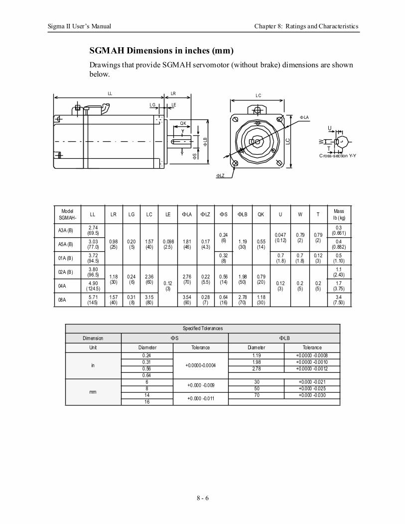
Sigma II User’s Manual Chapter 8: Ratings and Characteristics
8 - 6
SGMAH Dimensions in inches (mm)Drawings that provide SGMAH servomotor (without brake) dimensions are shown below.
ModelSGMAH- LL LR LG LC LE ΦLA ΦLZ ΦS ΦLB QK U W T Mass
lb (kg)
A3A (B) 2.74(69.5)
0.98(25)
0.20(5)
1.57(40)
0.098(2.5)
1.81(46)
0.17(4.3)
0.24(6) 1.19
(30)0.55(14)
0.047(0.12)
0.79(2)
0.79(2)
0.3(0.661)
A5A (B) 3.03(77.0)
0.4(0.882)
01A (B) 3.72(94.5)
0.32(8)
0.7(1.8)
0.7(1.8)
0.12(3)
0.5(1.10)
02A (B) 3.80(96.5) 1.18
(30)0.24(6)
2.36(60) 0.12
(3)
2.76(70)
0.22(5.5)
0.56(14)
1.98(50)
0.79(20) 0.12
(3)0.2(5)
0.2(5)
1.1(2.43)
04A 4.90(124.5)
1.7(3.75)
08A 5.71(145)
1.57(40)
0.31(8)
3.15(80)
3.54(90)
0.28 (7)
0.64(16)
2.78(70)
1.18(30)
3.4(7.50)
Specified Tolerances
Dimension ΦS ΦLB
Unit Diameter Tolerance Diameter Tolerance
in
0.24
+0.0000-0.0004
1.19 +0.0000 -0.00080.31 1.98 +0.0000 -0.00100.56 2.78 +0.0000 -0.00120.64
mm
6 +0.000 -0.009 30 +0.000 -0.0218 50 +0.000 -0.025
14 +0.000 -0.011 70 +0.000 -0.03016
Cross-section Y-Y
U
W
T
L C
Y
YQK
ΦLB
ΦLA
ΦLZ
LC
Y
Y
LL
ΦS
LR
LEL G
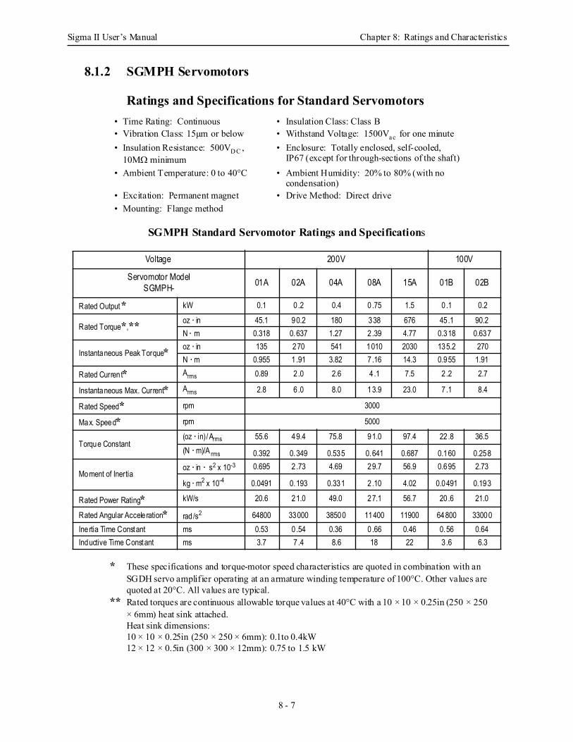
Sigma II User’s Manual Chapter 8: Ratings and Characteristics
8 - 7
8.1.2 SGMPH Servomotors
Ratings and Specifications for Standard Servomotors
SGMPH Standard Servomotor Ratings and Specifications
* These specifications and torque-motor speed characteristics are quoted in combination with an SGDH servo amplifier operating at an armature winding temperature of 100°C. Other values are quoted at 20°C. All values are typical.
** Rated torques are continuous allowable torque values at 40°C with a 10 × 10 × 0.25in (250 × 250 × 6mm) heat sink attached.Heat sink dimensions:10 × 10 × 0.25in (250 × 250 × 6mm): 0.1to 0.4kW12 × 12 × 0.5in (300 × 300 × 12mm): 0.75 to 1.5 kW
• Time Rating: Continuous • Insulation Class: Class B• Vibration Class: 15µm or below • Withstand Voltage: 1500Va c for one minute• Insulation Resistance: 500VD C ,
10MΩ minimum• Enclosure: Totally enclosed, self-cooled,
IP67 (except for through-sections of the shaft)• Ambient Temperature: 0 to 40°C • Ambient Humidity: 20% to 80% (with no
condensation)• Excitation: Permanent magnet • Drive Method: Direct drive• Mounting: Flange method
Voltage 200V 100V
Servomotor ModelSGMPH- 01A 02A 04A 08A 15A 01B 02B
Rated Output * kW 0.1 0.2 0.4 0 .75 1.5 0 .1 0.2
Rated Torque*,** oz · in 45.1 90.2 180 338 676 45.1 90.2N · m 0.318 0.637 1.27 2.39 4.77 0.318 0.637
Instantaneous Peak Torque* oz · in 135 270 541 1010 2030 135.2 270N · m 0.955 1.91 3.82 7.16 14.3 0.955 1.91
Rated Curren t* Arms 0.89 2.0 2.6 4 .1 7.5 2 .2 2.7
Instantaneous Max. Current* Arms 2.8 6 .0 8.0 13.9 23.0 7 .1 8.4
Rated Speed* rpm 3000
Max. Speed* rpm 5000
Torque Constant(oz · in)/Arms 55.6 49.4 75.8 91.0 97.4 22.8 36.5(N · m)/A rms 0.392 0.349 0.535 0.641 0.687 0.160 0.258
Moment of Inertiaoz · in · s2 x 10-3 0.695 2.73 4.69 29.7 56.9 0.695 2.73
kg · m2 x 10-4 0.0491 0.193 0.331 2.10 4.02 0.0491 0.193
Rated Power Rating* kW/s 20.6 21.0 49.0 27.1 56.7 20.6 21.0
Rated Angular Accele ration* rad /s2 64800 33000 38500 11400 11900 64800 33000Inertia Time Constant ms 0.53 0.54 0.36 0.66 0.46 0.56 0.64Inductive Time Constant ms 3.7 7 .4 8.6 18 22 3.6 6.3

Sigma II User’s Manual Chapter 8: Ratings and Characteristics
8 - 8
SGMPH Servomotor Motor Speed/Torque Characteristics The torque-motor speed characteristics are shown below for SGMPH servomotors.• 200V
SGMPH - 04
SP
EE
D (r
pm) 4000
3000
2000
1000
5000
0
BA
0 1 2 3 4TORQUE (N · m)
0 200 400 600TORQUE (oz · in)
BA
SGMPH - 15
SP
EE
D (r
pm) 4000
3000
2000
1000
5000
0
0 800 1600 2400TORQUE (oz · in)
0 4 8 12 16TORQUE (N · m)
BA
SGMPH - 08S
PE
ED
(rpm
) 4000
3000
2000
1000
5000
00 2 4 6 8
TORQUE (N · m)
0 400 800 1200TORQUE (oz · in)
SGMPH - 02
SP
EE
D (r
pm) 4000
3000
2000
1000
5000
0
BA
0 0.5 1 1.5 2
0 100 200 300
TORQUE (N · m)
TORQUE (oz · in)
SGMPH - 01S
PE
ED
(rpm
) 4000
3000
2000
1000
5000
0
BA
TORQUE (oz · in)0 50 100 150
0 0.25 0.5 0.75 1.0TORQUE (N · m)
CONTINUOUSDUTY ZONE
INTERMITTENTDUTY ZONE
A : B :
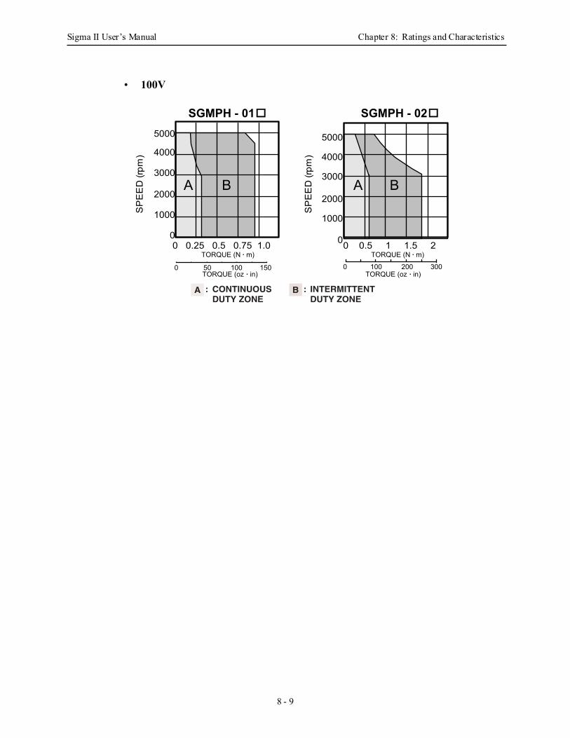
Sigma II User’s Manual Chapter 8: Ratings and Characteristics
8 - 9
• 100V
BA
TORQUE (oz · in)0 50 100 150
0 0.25 0.5 0.75 1.0TORQUE (N · m)
SGMPH - 01
SP
EE
D (r
pm)
SGMPH - 02
BA
0 100 200 300TORQUE (oz · in)
0 0.5 1 1.5 2TORQUE (N · m)
SP
EE
D (r
pm) 4000
3000
2000
1000
5000
0
4000
3000
2000
1000
5000
0
CONTINUOUSDUTY ZONE
INTERMITTENTDUTY ZONE
A : B :
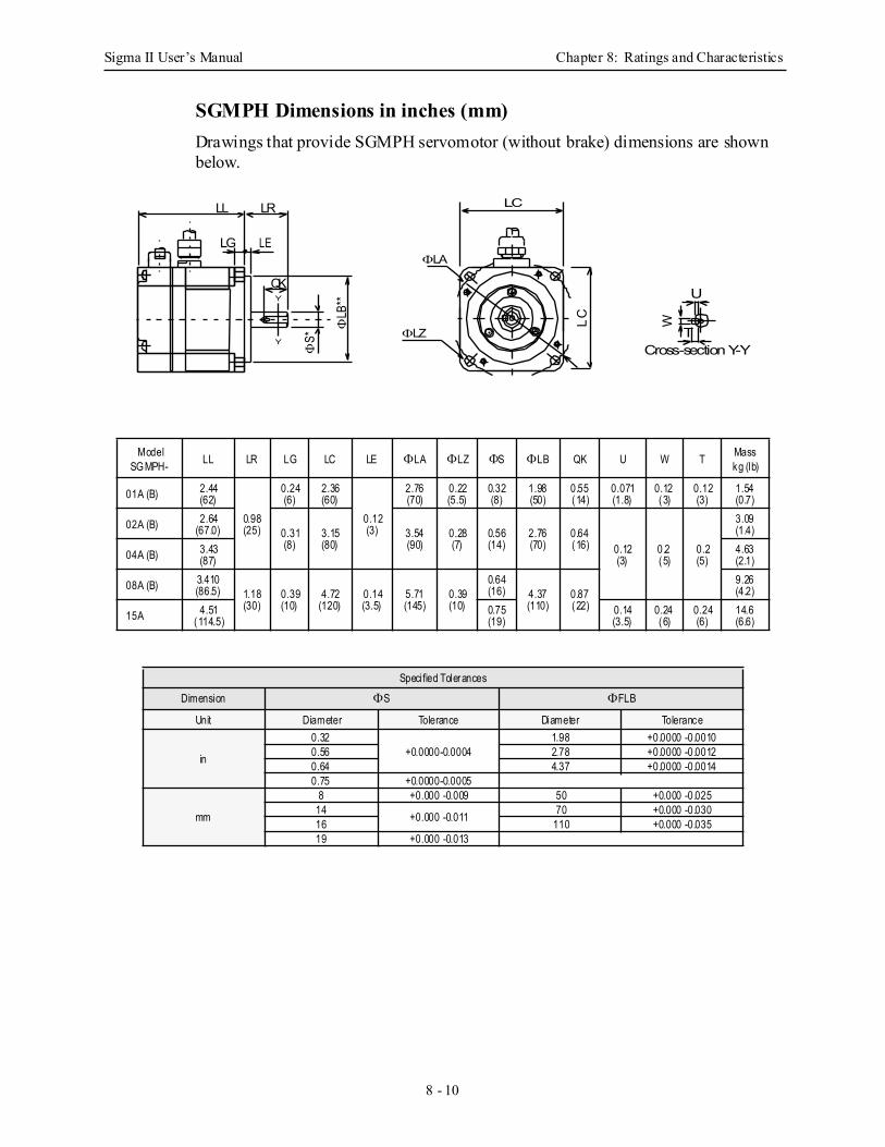
Sigma II User’s Manual Chapter 8: Ratings and Characteristics
8 - 10
SGMPH Dimensions in inches (mm)Drawings that provide SGMPH servomotor (without brake) dimensions are shown below.
ModelSGMPH- LL LR LG LC LE ΦLA ΦLZ ΦS ΦLB QK U W T Mass
kg (lb)
01A (B) 2.44(62)
0.98(25)
0.24(6)
2.36(60)
0.12(3)
2.76(70)
0.22(5.5)
0.32(8)
1.98(50)
0.55(14)
0.071(1.8)
0.12(3)
0.12(3)
1.54(0.7)
02A (B) 2.64(67.0) 0.31
(8)3.15(80)
3.54(90)
0.28(7)
0.56(14)
2.76(70)
0.64(16) 0.12
(3)0.2(5)
0.2(5)
3.09(1.4)
04A (B) 3.43(87)
4.63(2.1)
08A (B) 3.410(86.5) 1.18
(30)0.39 (10)
4.72(120)
0.14(3.5)
5.71(145)
0.39 (10)
0.64(16) 4.37
(110)0.87(22)
9.26(4.2)
15A 4.51(114.5)
0.75(19)
0.14(3.5)
0.24(6)
0.24(6)
14.6(6.6)
Specified Tolerances
Dimension ΦS ΦFLB
Unit Diameter Tolerance Diameter Tolerance
in
0.32+0.0000-0.0004
1.98 +0.0000 -0.00100.56 2.78 +0.0000 -0.00120.64 4.37 +0.0000 -0.00140.75 +0.0000-0.0005
mm
8 +0.000 -0.009 50 +0.000 -0.02514 +0.000 -0.011 70 +0.000 -0.03016 110 +0.000 -0.03519 +0.000 -0.013
LC
ΦLA
LC
ΦLZ
LL LR
Y
Y
LG LE
QK
ΦS*
ΦLB
**T
U
W
Cross-section Y-Y
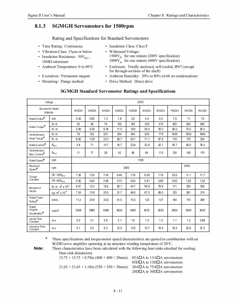
Sigma II User’s Manual Chapter 8: Ratings and Characteristics
8 - 11
8.1.3 SGMGH Servomotors for 1500rpm
Rating and Specifications for Standard Servomotors
SGMGH Standard Servomotor Ratings and Specifications
* These specifications and torque-motor speed characteristics are quoted in combination with an SGDH servo amplifier operating at an armature winding temperature of 20°C.
Note: These characteristics have been calculated with the following heat sinks attached for cooling:Heat sink dimensions15.75 × 15.75 × 0.79in (400 × 400 × 20mm): 05A A to 13A A servomotors
05D A to 13D A servomotors21.65 × 21.65 × 1.18in (550 × 550 × 30mm): 20A A to 75A A servomotors
20D A to 30D A servomotors
• Time Rating: Continuous • Insulation Class: Class F• Vibration Class: 15µm or below • Withstand Voltage:
1500Vac for one minute (200V specification)1800Vac for one minute (400V specification)
• Insulation Resistance: 50VDC , 10MΩ minimum
• Enclosure: Totally enclosed, self-cooled, IP67 (except for through-sections of the shaft)
• Ambient Temperature: 0 to 40°C
• Excitation: Permanent magnet • Ambient Humidity: 20% to 80% (with no condensation)• Mounting: Flange method • Drive Method: Direct drive
Volta ge 200V
Se rvomo to r Mode lSGM GH -
05 A A 0 9A A 13 A A 2 0A A 3 0A A 44 A A 55 A A 7 5A A 1AA A 1EA A
R ated Ou tp ut* kW 0.45 0.85 1.3 1.8 2.9 4.4 5.5 7.5 11 15
R ated To rque* lb · in 25 48 74 102 165 252 310 425 620 845N · m 2.84 5.39 8.34 11.5 18.6 28.4 35.0 48.0 70.0 95.4
Ins ta ntan eou s Pe ak Torq ue*
lb · in 79 122 207 254 404 630 775 1050 1550 1984N · m 8.92 13.8 23.3 28.7 45.1 71.1 87.6 119 175 224
R ated C urre nt* Arm s 3.8 7.1 10.7 16.7 23.8 32.8 42.1 54.7 58.6 78.0
Ins ta ntan eou s Ma x. C urre nt* Arm s 11 17 28 42 56 84 110 130 140 170
R ated S pee d* rpm 1500
Ma ximu m Sp ee d* rpm 3000 2000
Tor queC on sta nt
( lb · in)/Arm s 7.26 7.35 7.43 6.46 7.35 8.05 7.79 8.23 11.1 11.7
(N · m)/Arm s 0.82 0.83 0.84 0.73 0.83 0.91 0.88 0.93 1.25 1.32
Mo men t o fIne rtia
lb · in · s2 x 10-3 6.41 12.3 18.2 28.1 40.7 59.8 78.8 111 250 355
kg · m2 x 10-4 7.24 13.9 20.5 31.7 46.0 67.5 89.0 125 281 315R ated P owe r R atin g* kW/s 11.2 20.9 33.8 41.5 75.3 120 137 184 174 289
R ated An gu larAcc ele ratio n* rad/s2 3930 3880 4060 3620 4050 4210 3930 3850 2490 3030
Ine rtia Time C on sta nt m s 5.0 3.1 2.8 2.1 1.9 1.3 1.3 1.1 1.2 0.98
Ind uctiv e Time C on sta nt m s 5.1 5.3 6.3 12.5 12.5 15.7 16.4 18.4 22.6 27.2
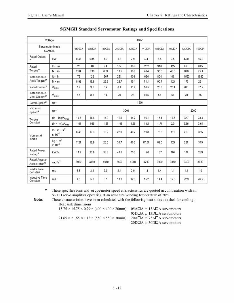
Sigma II User’s Manual Chapter 8: Ratings and Characteristics
8 - 12
SGMGH Standard Servomotor Ratings and Specifications
* These specifications and torque-motor speed characteristics are quoted in combination with an SGDH servo amplifier operating at an armature winding temperature of 20°C.
Note: These characteristics have been calculated with the following heat sinks attached for cooling:Heat sink dimensions15.75 × 15.75 × 0.79in (400 × 400 × 20mm): 05A A to 13A A servomotors
05D A to 13D A servomotors21.65 × 21.65 × 1.18in (550 × 550 × 30mm): 20A A to 75A A servomotors
20D A to 30D A servomotors
Voltage 400V
Servomotor ModelSGMGH-
05D A 09 D A 13 D A 20D A 30 D A 44 D A 55 D A 7 5D A 1 AD A 1 ED A
Rated Output * kW 0.45 0.85 1.3 1.8 2.9 4.4 5.5 7.5 44.0 15.0
Rated T orque*
lb · in 25 48 74 102 165 252 310 425 620 845N · m 2.84 5.39 8.34 11.5 18.6 28.4 35.0 48.0 70.0 95.4
Instantaneous Peak T orque*
lb · in 79 122 207 254 404 630 804 1091 1550 1960N · m 8.92 13.8 23.3 28.7 45.1 71.1 90.7 123 175 221
Rated Curren* Ar ms 1.9 3.5 5.4 8.4 11.9 16.5 20.8 25.4 28.1 37.2
Instantaneous Max. C ur rent* Ar ms 5.5 8.5 14 20 28 40.5 55 65 70 85
Rated Speed* rpm 1500
Maximum Speed* rpm 3000 2000
T orqueConstant
(lb · in)/Arm s 14.5 14.6 14.9 12.6 14.7 16.1 15.4 17.7 22.7 23.4
(N · m)/Arm s 1.64 1.65 1.68 1.46 1.66 1.82 1.74 2.0 2.56 2.64
Moment ofInertia
lb · in · s 2
x 10-3 6.42 12.3 18.2 28.0 40.7 59.8 78.8 111 250 355
kg · m2
x 10-4 7.24 13.9 20.5 31.7 46.0 67.54 89.0 125 281 315
Rated Power Rating* kW/s 11.2 20.9 33.8 41.5 75.3 120 137 184 174 289
Rated Angular Acceleration* rad/s 2 3930 3880 4060 3620 4050 4210 3930 3850 2490 3030
Inertia Time Constant ms 5.6 3.1 2.9 2.4 2.0 1.4 1.4 1.1 1.1 1.0
Inductive T ime Constant ms 4.5 5.3 6.1 11.1 12.3 15.2 14.4 17.6 22.9 26.2
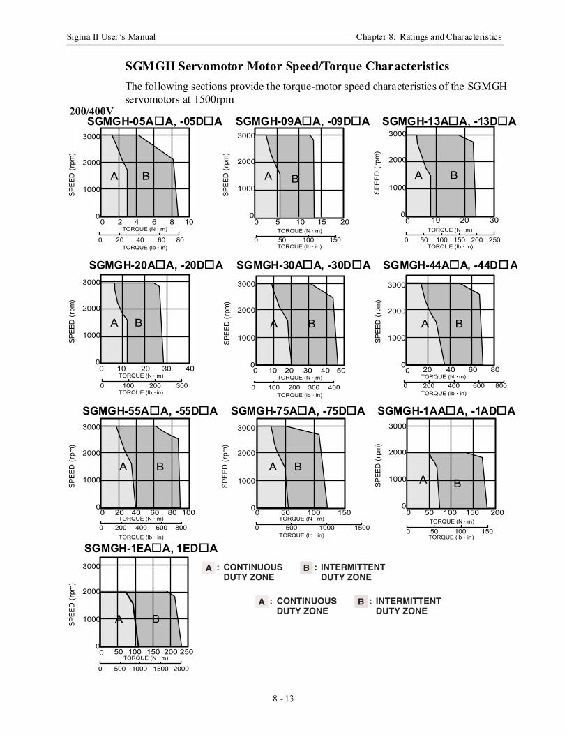
Sigma II User’s Manual Chapter 8: Ratings and Characteristics
8 - 13
SGMGH Servomotor Motor Speed/Torque Characteristics The following sections provide the torque-motor speed characteristics of the SGMGH servomotors at 1500rpm
SPEE
D (r
pm)
0 50 100 150TORQUE (N · m)
TORQUE (lb · in)
SPEE
D (r
pm)
3000
2000
1000
00 5 10 15 20
BA
0 50 100 150TORQUE (N · m)
TORQUE (lb · in)
SPEE
D (r
pm)
3000
2000
1000
00 50 100 150 200
BA
SPEE
D (r
pm)
3000
2000
1000
0
BA
0 50 100 150 200 250TORQUE (N · m)
0 500 1000 1500 2000
3000
2000
1000
0
B A
0 20 40 60 80 100TORQUE (N · m)
TORQUE (lb · in)
0 200 400 600 800
0 50 100 150TORQUE (N · m)
TORQUE (lb · in)0 500 1000 1500
BA
SPEE
D (r
pm)
3000
2000
1000
0
TORQUE (N · m)
TORQUE (lb · in)
0 20 40 60 80
0 200 400 600 800SP
EED
(rpm
)
3000
2000
1000
0
BA
SPEE
D (r
pm)
3000
2000
1000
0TORQUE (N · m)
TORQUE (lb · in)0 100 200 300 400
0 10 20 30 40 50
BA
SPEE
D (r
pm)
3000
2000
1000
0
BA
0 10 20 30 40
0 100 200 300TORQUE (N · m)
TORQUE (lb · in)
SPEE
D (r
pm)
3000
2000
1000
0
BA
TORQUE (N · m)
TORQUE (lb · in)0 50 100 150 200
0 10 20 30
250
SPEE
D (r
pm)
3000
2000
1000
0
BA
0 2 4 6 8 10TORQUE (N · m)
TORQUE (lb · in)0 20 40 60 80
CONTINUOUSDUTY ZONE
INTERMITTENTDUTY ZONE
A : B :
CONTINUOUSDUTY ZONE
INTERMITTENTDUTY ZONE
A : B :
200/400VSGMGH-05A A, -05D A SGMGH-09A A, -09D A SGMGH-13A A, -13D A
SGMGH-20A A, -20D A SGMGH-30A A, -30D A SGMGH-44A A, -44D A
SGMGH-55A A, -55D A SGMGH-75A A, -75D A SGMGH-1AA A, -1AD A
SGMGH-1EA A, 1ED A
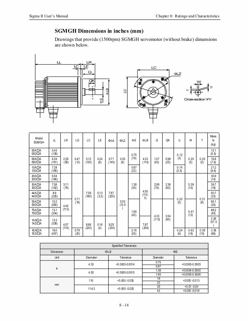
Sigma II User’s Manual Chapter 8: Ratings and Characteristics
8 - 14
SGMGH Dimensions in inches (mm) Drawings that provide (1500rpm) SGMGH servomotor (without brake) dimensions are shown below.
ModelSGMGH- LL LR LG LC LE ΦLA ΦLZ ΦS ΦLB Q QK U W T
Mass lb
(kg)
05A A05D A
5.43(138)
2.28(58)
0.47(12)
5.12(130)
0.24(6)
5.71(145)
0.35(9)
0.75(19) 4.33
(110)1.57(40)
0.98(25)
0.12(3) 0.20
(5)0.20(5)
12.1(5.5)
09A A09D A
6.34(161)
16.8(7.6)
13A A13D A
7.28(185)
0.87(22)
0.14(3.5)
21.2(9.6)
20A A20D A
6.54(166)
3.11(79)
0.71(18)
7.09(180)
0.13(3.2)
7.87(200)
0.53(13.5
)
1.38(35)
4.50(114.
3)
2.99(76)
2.36(60)
0.20(5)
0.39(10)
0.31(8)
30.9(14)
30A A30D A
7.56(192)
39.7(18)
44A A44D A
8.9(226)
50.7(23)
55A A55D A
10.2(260) 4.45
(113)1.65(42) 4.33
(110)3.54(90)
0.47(12)
66.1(30)
75A A75D A
13.1(334)
88.2(40)
1AA A1AD A
13.3(338) 4.57
(116)8.66(220)
0.16(4)
9.25(235)
7.87(200)
2.26(57.5
)1EA A1ED A
18.0(457)
0.79(20)
2.16(55)
0.24(6)
0.63(16)
0.39(10)
3.39(86)
Specified Tolerances
Dimension ΦLB ΦS
Unit Diameter Tolerance Diameter Tolerance
in4.33 +0.0000-0.0014 0.75 +0.0000-0.00050.87
4.50 +0.0000-0.0010 1.38 +0.0004-0.00001.65 +0.0000-0.0006
mm110 +0.000 -0.035 19 +0.000 -0.01322
114.3 +0.000 -0.025 35 +0.01 -0.0042 +0.000 -0.016
W
U
T
LC
LC
ΦLZ
ΦLB
ΦS
LL LRLC LE
Q
QK
Y
Y Cross-section Y-Y
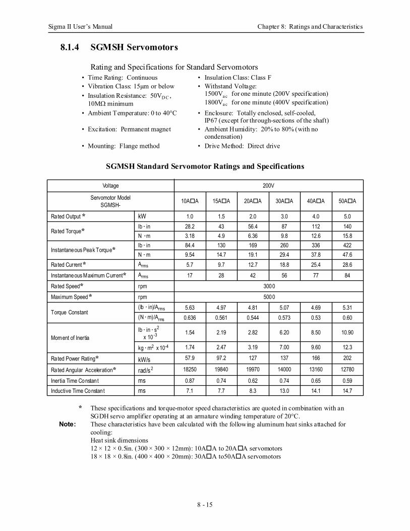
Sigma II User’s Manual Chapter 8: Ratings and Characteristics
8 - 15
8.1.4 SGMSH Servomotors
Rating and Specifications for Standard Servomotors
SGMSH Standard Servomotor Ratings and Specifications
* These specifications and torque-motor speed characteristics are quoted in combination with an SGDH servo amplifier operating at an armature winding temperature of 20°C.
Note: These characteristics have been calculated with the following aluminum heat sinks attached for cooling:Heat sink dimensions12 × 12 × 0.5in. (300 × 300 × 12mm): 10A A to 20A A servomotors18 × 18 × 0.8in. (400 × 400 × 20mm): 30A A to50A A servomotors
• Time Rating: Continuous • Insulation Class: Class F• Vibration Class: 15µm or below • Withstand Voltage:
1500Va c for one minute (200V specification)1800Va c for one minute (400V specification)
• Insulation Resistance: 50VD C , 10MΩ minimum
• Ambient Temperature: 0 to 40°C • Enclosure: Totally enclosed, self-cooled, IP67 (except for through-sections of the shaft)
• Excitation: Permanent magnet • Ambient Humidity: 20% to 80% (with no condensation)
• Mounting: Flange method • Drive Method: Direct drive
Voltage 200V
Servomotor ModelSGMSH- 10A A 15A A 20A A 30A A 40A A 50A A
Rated Output * kW 1.0 1.5 2.0 3.0 4.0 5.0
Rated Torque* lb · in 28.2 43 56.4 87 112 140N · m 3.18 4.9 6.36 9.8 12.6 15.8
Instantaneous Peak Torque* lb · in 84.4 130 169 260 336 422N · m 9.54 14.7 19.1 29.4 37.8 47.6
Rated Current* Arms 5.7 9.7 12.7 18.8 25.4 28.6
Instantaneous Maximum Current* Arms 17 28 42 56 77 84
Rated Speed* rpm 3000
Maximum Speed* rpm 5000
Torque Constant(lb · in)/Arms 5.63 4.97 4.81 5.07 4.69 5.31(N · m)/Arms 0.636 0.561 0.544 0.573 0.53 0.60
Moment of Inertialb · in · s2 x 10 -3 1.54 2.19 2.82 6.20 8.50 10.90
kg · m2 x 10-4 1.74 2.47 3.19 7.00 9.60 12.3
Rated Power Rating* kW/s 57.9 97.2 127 137 166 202
Rated Angular Acceleration* rad/s2 18250 19840 19970 14000 13160 12780
Inertia Time Constan t ms 0.87 0.74 0.62 0.74 0.65 0.59Inductive Time Constan t ms 7.1 7.7 8.3 13.0 14.1 14.7
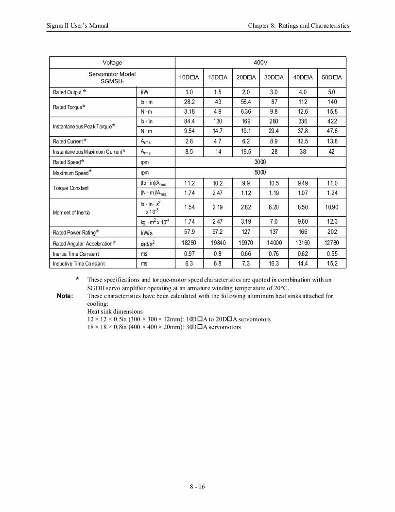
Sigma II User’s Manual Chapter 8: Ratings and Characteristics
8 - 16
* These specifications and torque-motor speed characteristics are quoted in combination with an SGDH servo amplifier operating at an armature winding temperature of 20°C.
Note: These characteristics have been calculated with the following aluminum heat sinks attached for cooling:Heat sink dimensions12 × 12 × 0.5in (300 × 300 × 12mm): 10D A to 20D A servomotors18 × 18 × 0.8in (400 × 400 × 20mm): 30D A servomotors
Voltage 400V
Servomotor ModelSGMSH- 10D A 15D A 20D A 30D A 40D A 50D A
Rated Output * kW 1.0 1.5 2.0 3.0 4.0 5.0
Rated Torque*lb · in 28.2 43 56.4 87 112 140N · m 3.18 4.9 6.36 9.8 12.6 15.8
Instantaneous Peak Torque*lb · in 84.4 130 169 260 336 422N · m 9.54 14.7 19.1 29.4 37.8 47.6
Rated Current* Arms 2.8 4.7 6.2 8.9 12.5 13.8Instantaneous Maximum Current* Arms 8.5 14 19.5 28 38 42Rated Speed* rpm 3000Maximum Speed* rpm 5000
Torque Constant(lb · in)/Arms 11.2 10.2 9.9 10.5 9.49 11.0(N · m)/Arms 1.74 2.47 1.12 1.19 1.07 1.24
Moment of Inertialb · in · s2
x 10-3 1.54 2.19 2.82 6.20 8.50 10.90
kg · m2 x 10-4 1.74 2.47 3.19 7.0 9.60 12.3Rated Power Rating* kW/s 57.9 97.2 127 137 166 202
Rated Angular Acceleration* rad/s2 18250 19840 19970 14000 13160 12780Inertia Time Constan t ms 0.97 0.8 0.66 0.76 0.62 0.55Inductive Time Constan t ms 6.3 6.8 7.3 16.3 14.4 15.2
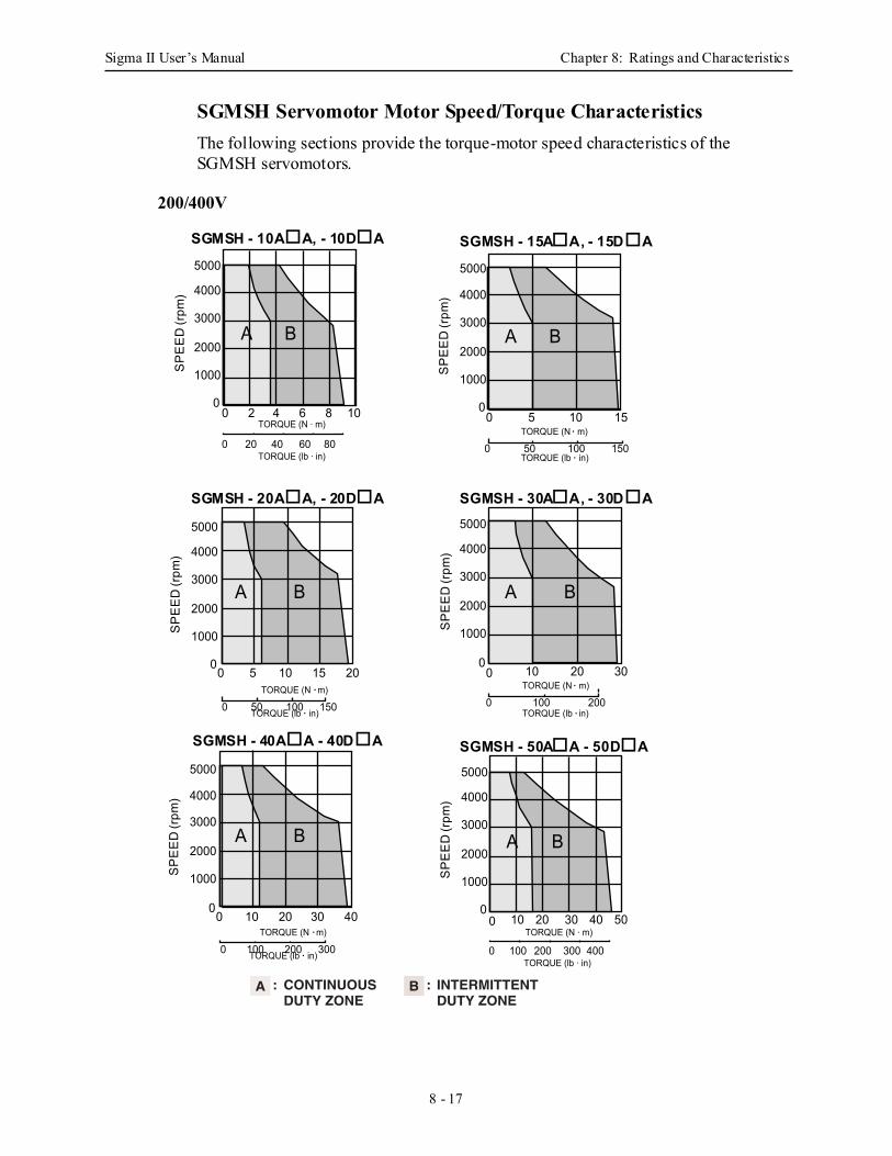
Sigma II User’s Manual Chapter 8: Ratings and Characteristics
8 - 17
SGMSH Servomotor Motor Speed/Torque Characteristics The following sections provide the torque-motor speed characteristics of the SGMSH servomotors.
0 100 200
BA
0 5 10 15
SP
EE
D (r
pm) 4000
3000
2000
1000
5000
0
TORQUE (N · m)
TORQUE (lb · in)0 50 100 150
BA
SP
EE
D (r
pm) 4000
3000
2000
1000
5000
00 2 4 6 8 10
TORQUE (N · m)
TORQUE (lb · in)0 20 40 60 80
TORQUE (N · m)
TORQUE (lb · in)
0 10 20 30
SP
EE
D (r
pm) 4000
3000
2000
1000
5000
0
BA
SP
EE
D (r
pm) 4000
3000
2000
1000
5000
0
BA
0 5 10 2015TORQUE (N · m)
0 50 100 150TORQUE (lb · in)
SP
EE
D (r
pm) 4000
3000
2000
1000
5000
0
BA
0 10 20 4030TORQUE (N · m)
0 100 200 300TORQUE (lb · in)
BA
SP
EE
D (r
pm) 4000
3000
2000
1000
5000
00 10 20 30 40 50
TORQUE (N · m)
TORQUE (lb · in)0 100 200 300 400
200/400V
CONTINUOUSDUTY ZONE
INTERMITTENTDUTY ZONE
A : B :
SGMSH - 10A A, - 10D A SGMSH - 15A A, - 15D A
SGMSH - 30A A, - 30D ASGMSH - 20A A, - 20D A
SGMSH - 40A A - 40D A SGMSH - 50A A - 50D A
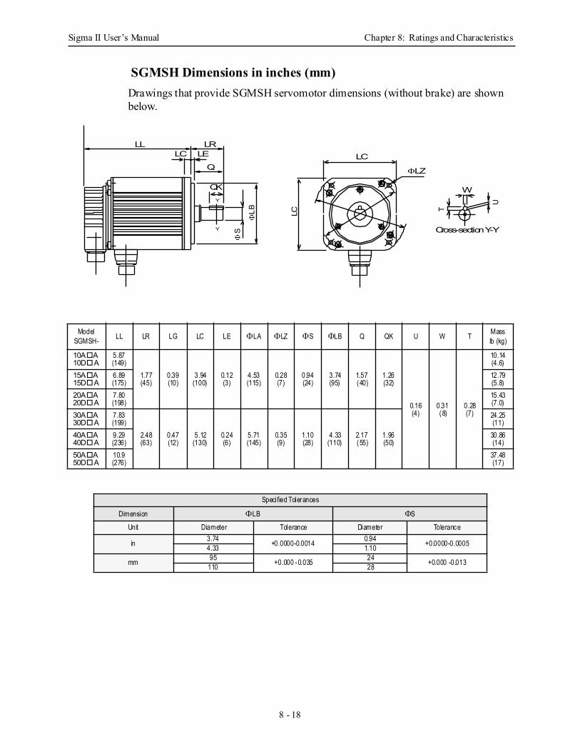
Sigma II User’s Manual Chapter 8: Ratings and Characteristics
8 - 18
SGMSH Dimensions in inches (mm)Drawings that provide SGMSH servomotor dimensions (without brake) are shown below.
ModelSGMSH- LL LR LG LC LE ΦLA ΦLZ ΦS ΦLB Q QK U W T Mass
lb (kg)
10A A10D A
5.87(149)
1.77(45)
0.39(10)
3.94(100)
0.12(3)
4.53(115)
0.28(7)
0.94(24)
3.74(95)
1.57(40)
1.26(32)
0.16(4)
0.31(8)
0.28(7)
10.14(4.6)
15A A15D A
6.89(175)
12.79(5.8)
20A A20D A
7.80(198)
15.43(7.0)
30A A30D A
7.83(199)
2.48(63)
0.47(12)
5.12(130)
0.24(6)
5.71(145)
0.35(9)
1.10(28)
4.33(110)
2.17(55)
1.96(50)
24.25(11)
40A A40D A
9.29(236)
30.86(14)
50A A50D A
10.9(276)
37.48(17)
Specified Tolerances
Dimension ΦLB ΦS
Unit Diameter Tolerance Diameter Tolerance
in 3.74 +0.0000-0.0014 0.94 +0.0000-0.00054.33 1.10
mm 95 +0.000 -0.035 24 +0.000 -0.013110 28
W
U
T
LC
LC
ΦLZ
ΦLB
ΦS
LL LRLC LE
Q
QKY
Y Cross-section Y-Y
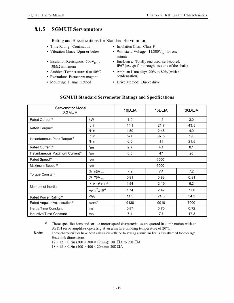
Sigma II User’s Manual Chapter 8: Ratings and Characteristics
8 - 19
8.1.5 SGMUH Servomotors
Rating and Specifications for Standard Servomotors
SGMUH Standard Servomotor Ratings and Specifications
* These specifications and torque-motor speed characteristics are quoted in combination with an SGDH servo amplifier operating at an armature winding temperature of 20°C.
Note: These characteristics have been calculated with the following aluminum heat sinks attached for cooling:Heat sink dimensions12 × 12 × 0.5in (300 × 300 × 12mm): 10D A to 20D A18 × 18 × 0.8in (400 × 400 × 20mm): 30D A
• Time Rating: Continuous • Insulation Class: Class F• Vibration Class: 15µm or below • Withstand Voltage: 11,800Vac for one
minute• Insulation Resistance: 500VD C ,
10MΩ minimum• Enclosure: Totally enclosed, self-cooled,
IP67 (except for through-sections of the shaft)• Ambient Temperature: 0 to 40°C • Ambient Humidity: 20% to 80% (with no
condensation)• Excitation: Permanent magnet• Mounting: Flange method • Drive Method: Direct drive
Servomotor ModelSGMUH- 10D A 15D A 30D A
Rated Output * kW 1.0 1.5 3.0
Rated Torque* lb · in 14.1 21.7 43.5N · m 1.59 2.45 4.9
Instantaneous Peak Torque* lb · in 57.6 97.5 190N · m 6.5 11 21.5
Rated Current* Arms 2.7 4.1 8.1
Instantaneous Maximum Current* Arms 8.5 47 28
Rated Speed* rpm 6000
Maximum Speed* rpm 6000
Torque Constant(lb · in)/Arms 7.2 7.4 7.2(N · m)/Arms 0.81 0.83 0.81
Moment of Inertialb · in · s2 x 10-3 1.54 2.19 6.2
kg · m2 x 10-4 1.74 2.47 7.00
Rated Power Rating* kW/s 14.5 24.3 34.3
Rated Angular Acceleration* rad/s2 9130 9910 7000Inertia Time Constant ms 0.87 0.70 0.72Inductive Time Constant ms 7.1 7.7 17.3
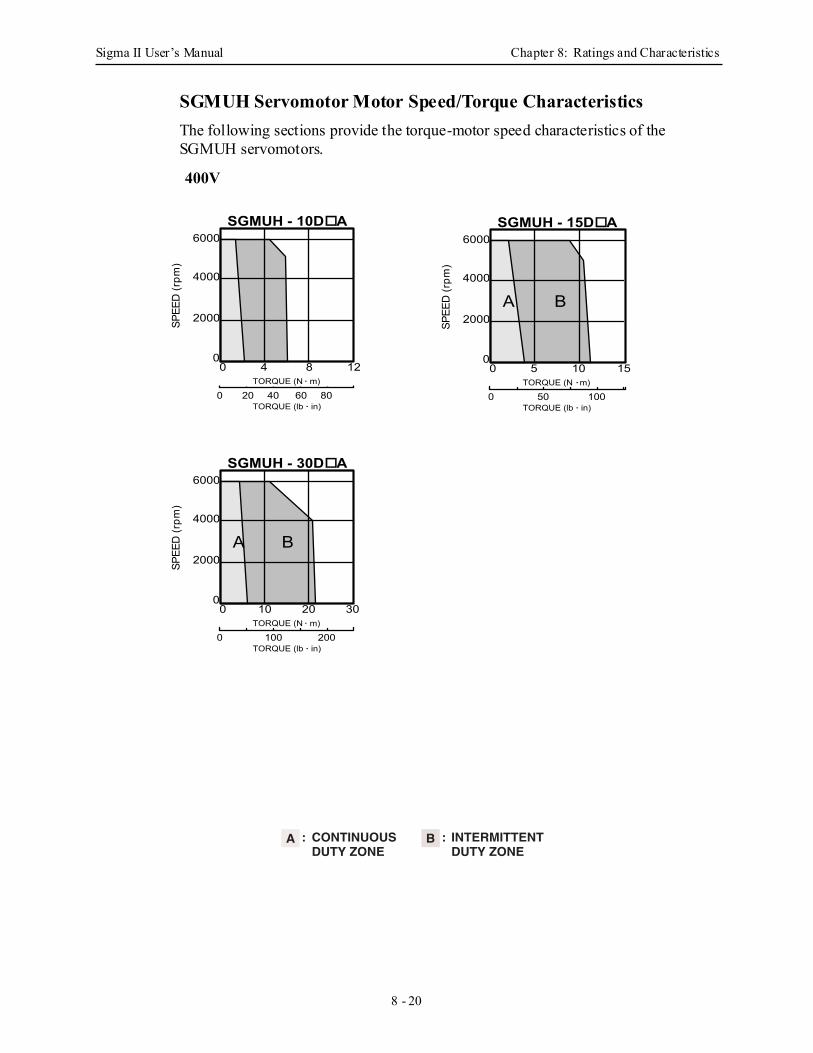
Sigma II User’s Manual Chapter 8: Ratings and Characteristics
8 - 20
SGMUH Servomotor Motor Speed/Torque Characteristics The following sections provide the torque-motor speed characteristics of the SGMUH servomotors.
TORQUE (N · m)
TORQUE (lb · in)0 20 40 60 80
SPEE
D (r
pm)
6000
4000
2000
00 4 8 12
SGMUH - 10D A
TORQUE (N · m)
TORQUE (lb · in)0 100 200
SPEE
D (r
pm)
6000
4000
2000
00 10 20 30
BA
SGMUH - 30D A
TORQUE (N · m)
TORQUE (lb · in)0 50 100
SPEE
D (r
pm)
6000
4000
2000
00 5 10 15
BA
SGMUH - 15D A
CONTINUOUSDUTY ZONE
INTERMITTENTDUTY ZONE
A : B :
400V
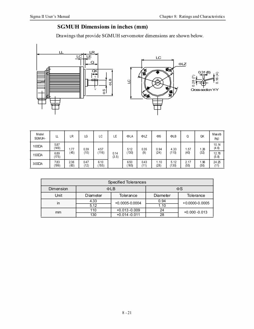
Sigma II User’s Manual Chapter 8: Ratings and Characteristics
8 - 21
SGMUH Dimensions in inches (mm) Drawings that provide SGMUH servomotor dimensions are shown below.
ModelSGMUH- LL LR LG LC LE ΦLA ΦLZ ΦS ΦLB Q QK Mass lb
(kg)
10D A 5.87(149) 1.77
(45)0.39(10)
4.57(116) 0.14
(3.5)
5.12(130)
0.35(9)
0.94(24)
4.33(110)
1.57(40)
1.26(32)
10.14(4.6)
15D A 6.89(175)
12.78(5.8)
30D A 7.83(199)
2.36(60)
0.47(12)
6.10(155)
6.50(165)
0.43(11)
1.10(28)
5.12(130)
2.17(55)
1.96(50)
24.25(11)
Specified TolerancesDimension ΦLB ΦS
Unit Diameter Tolerance Diameter Tolerance
in 4.33 +0.0005-0.0004 0.94 +0.0000-0.00055.12 1.10
mm 110 +0.013 -0.009 24 +0.000 -0.013130 +0.014 -0.011 28
0.31 (8)
0.16
(4)
0.28
(7)
LC
LC
ΦLZ
ΦLB
ΦS
LL LRLC LE
Q
QKY
Y Cross-section Y-Y
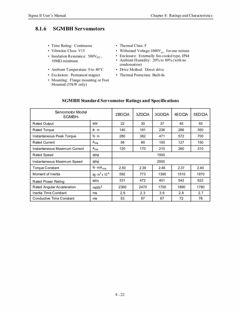
Sigma II User’s Manual Chapter 8: Ratings and Characteristics
8 - 22
8.1.6 SGMBH Servomotors
SGMBH Standard Servomotor Ratings and Specifications
• Time Rating: Continuous • Thermal Class: F• Vibration Class: V15 • Withstand Voltage:1800Va c for one minute
• Enclosure: Externally fan cooled type, IP44 • Ambient Humidity: 20% to 80% (with no
condensation)
• Insulation Resistance: 500VD C , 10MΩ minimum
• Ambient Temperature: 0 to 40°C • Drive Method: Direct drive• Excitation: Permanent magnet • Thermal Protection: Built-In• Mounting: Flange mounting or Foot
Mounted (55kW only)
Servomotor ModelSGMBH- 2BD A 3ZD A 3GD A 4ED A 5ED A
Rated Output kW 22 30 37 45 55
Rated Torque lb · in 140 191 236 286 350
Instantaneous Peak Torque N · m 280 382 471 572 700
Rated Current Arms 58 80 100 127 150
Instantaneous Maximum Current Arms 120 170 210 260 310
Rated Speed RPM 1500
Instantaneous Maximum Speed RPM 2000
Torque Constant N · m/A rms 2.50 2.39 2.46 2.37 2.40
Moment of Inertia kg · m2 x 10-4 592 773 1390 1510 1970
Rated Power Rating kW/s 331 472 401 542 622
Rated Angular Acceleration rad/s2 2360 2470 1700 1890 1780Inertia Time Constant ms 2.6 2.3 3.6 2.8 2.7Conductive Time Constant ms 53 57 67 72 78
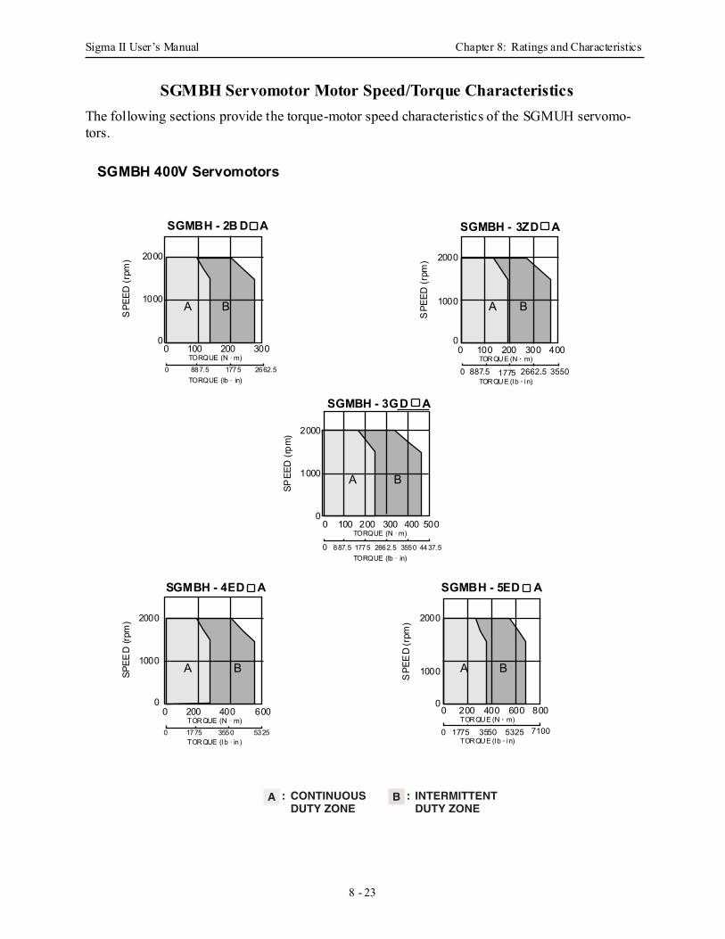
Sigma II User’s Manual Chapter 8: Ratings and Characteristics
8 - 23
SGMBH Servomotor Motor Speed/Torque Characteristics The following sections provide the torque-motor speed characteristics of the SGMUH servomo-tors.
CONTINUOUSDUTY ZONE
INTERMITTENTDUTY ZONE
A : B :
0 200 400 600
SPE
ED
(rpm
) 2000
1000
0
0 1775 3550 5325 7100TORQUE (N · m)
TORQUE (lb · in)
0 200 400 600 800
SGMBH - 5EA D
BASPEE
D (r
pm) 2000
1000
0
0 1775 3550 5325TORQUE (N · m)
TORQUE (lb · in)
SGMBH - 4EA D
BA
SGMBH - 3GA D
SPEE
D (r
pm) 2000
1000
0
TORQUE (N · m)
TORQUE (lb · in)0 887.5 1775 3550 4437.52662.5
0 100 200 300 400 500
B A
SPE
ED (r
pm) 2000
1000
0
0 887.5 1775 2662.5 3550TORQUE (N · m)
TORQUE (lb · in)
0 100 200 300 400
SGMBH - 3ZA D
B A
SPE
ED (r
pm) 2000
1000
00 100 200 300
0 887.5 1775 2662.5TORQUE (N · m)
TORQUE (lb · in)
SGMBH - 2BA D
BA
SGMBH 400V Servomotors
D A
D A D A
D A
D A
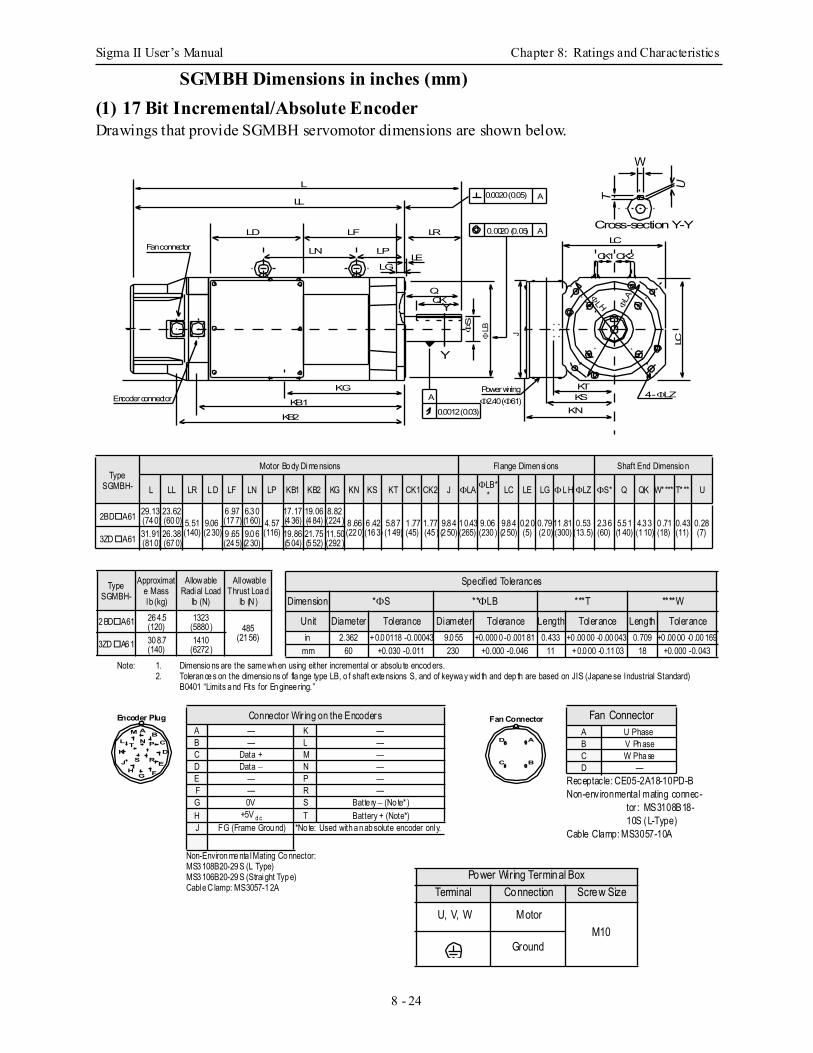
Sigma II User’s Manual Chapter 8: Ratings and Characteristics
8 - 24
SGMBH Dimensions in inches (mm) (1) 17 Bit Incremental/Absolute EncoderDrawings that provide SGMBH servomotor dimensions are shown below.
Note: 1. Dimensio ns are the same wh en using either incremental or absolu te encod ers.2. Toleran ce s on the dimensio ns of fla nge type LB, o f shaft exte nsions S, and of keywa y wid th and dep th are based on JIS (Japane se Industrial Standard)
B0401 “Limits a nd Fits for En ginee ring.”
Type SGMBH-
Motor Bo dy Dime nsions Flange Dimen sions Shaft End Dimensio n
L LL LR L D LF LN LP KB1 KB2 KG KN KS KT CK1 CK2 J ΦLA ΦLB** LC LE LG ΦL H ΦLZ ΦS* Q QK W**** T* ** U
2BD A61 29.13(74 0)
23.62(60 0) 5.51
(140)9.06(2 30)
6 .97(17 7)
6.3 0(1 60) 4.57
(116)
17.17(4 36)
19.06(4 84)
8.82(224 ) 8 .66
(22 0)6 .42(16 3)
5.8 7(1 49)
1 .77(45)
1.77(45 )
9.8 4(2 50)
1 0.43(265)
9.06(230 )
9.8 4(2 50)
0.2 0(5)
0.79(2 0)
11 .81(300)
0.53(13.5)
2.3 6(60)
5.5 1(1 40)
4.3 3(1 10)
0 .71(18)
0.43(11)
0.28(7)
3ZD A61 31.91(81 0)
26.38(67 0)
9 .65(24 5)
9.0 6(2 30)
19.86(5 04)
21.75(5 52)
11.50(292 )
A
A
0.0020 (0.05)
0.0020 (0.05)
0.0012 (0.03)
A
W
T
U
Y
Y
Cross-section Y-Y
KTKS
KN
LC
QQK
ΦS
ΦLB J
LC
4 - ΦLZ
LELG
LN
LF
LP
LD
LL
L
KG
KB1
KB2
CK1CK2
ΦLH ΦLA
Fan connector
Encoder connectorPower wiring
LR
Φ2.40 (Φ61)
Specified Tolerances
Dimension *ΦS **ΦLB ***T ****W
Unit Diameter Tolerance Diameter Tolerance Length Tolerance Length Tolerancein 2.362 +0.0 0118 -0.00043 9.0 55 +0.000 0 -0 .001 81 0.433 +0 .00 00 -0 .00 043 0.709 +0 .00 00 -0 .00 169
mm 60 +0.030 -0.011 230 +0.000 -0.046 11 +0.0 00 -0 .11 03 18 +0.000 -0.043
Type SGMBH-
Approximate Mass lb (kg)
Allow able Radial Load
lb (N)
Allowable Thrust Loa d
lb (N )
2 BD A61 26 4.5(120)
1323(5880 ) 485
(21 56)3ZD A6 1 30 8.7
(140)1410
(6272 )
AB
CD
MN PT
E
K
G F
J S R
L
H
Encoder Plug Fan Connector
Receptac le: CE05-2A18-10PD-BNon-environmental mating connec-
tor : MS3108B18-10S (L-Type)
Cable Clamp: MS3057-10A
Fan ConnectorA U PhaseB V Ph aseC W Pha seD —
A
B
D
C
Power Wiring Terminal Box
Terminal Connection Screw Size
U, V, W MotorM10
Ground
Non-Environ me nta l Mating Co nnector: MS3 108B20-29 S (L Type)MS3 106B20-29 S (Straight Typ e)Cable C lamp: MS3057-1 2A
Connector Wir ing on the EncodersA — K —B — L —C Data + M —D Data − N —E — P —F — R —G 0V S Batte ry − (No te* )H +5V d c T Battery + (Note*)J FG (Frame Grou nd) *No te: Used with a n ab solute encoder only.
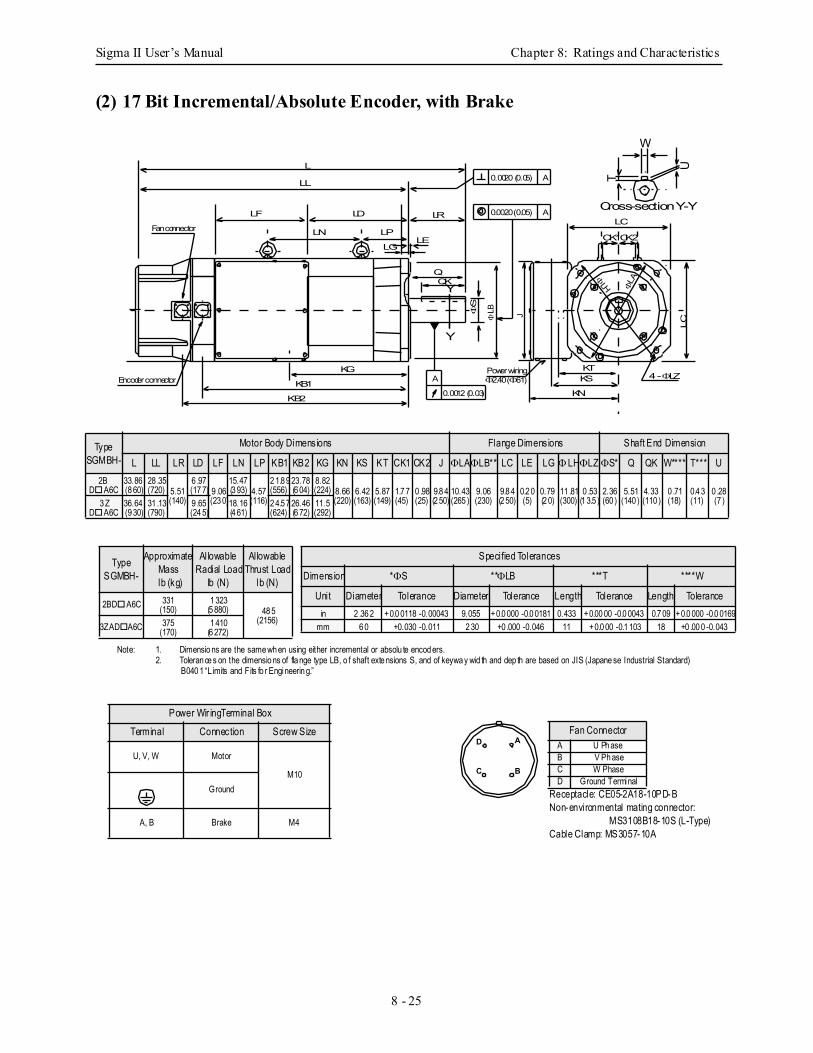
Sigma II User’s Manual Chapter 8: Ratings and Characteristics
8 - 25
(2) 17 Bit Incremental/Absolute Encoder, with Brake
Note: 1. Dimensio ns are the same wh en using either incremental or absolu te encod ers.2. Toleran ce s on the dimensio ns of fla nge type LB, o f shaft exte nsions S, and of keywa y wid th and dep th are based on JIS (Japane se Industrial Standard)
B040 1 “L imits and Fits fo r Engineerin g.”
Type SGMBH-
Motor Body Dimensions Flange Dimensions Shaft End Dimension
L LL LR LD LF LN LP KB1 KB2 KG KN KS KT CK1 CK2 J ΦLAΦLB** LC LE LG ΦLHΦLZ ΦS* Q QK W**** T*** U2B
D A6C33.86(8 60)
28 .35(720) 5.51
(140)
6 .97(17 7) 9 .06
(23 0)
15.47(3 93) 4.57
(116)
2 1.8 9(556)
23.78(6 04)
8.82(224) 8.66
(220)6.42(163)
5.87(149)
1.7 7(45)
0 .98(25)
9.8 4(2 50)
10.43(265 )
9.06(230)
9.8 4(2 50)
0.2 0(5)
0.79(2 0)
11 .81(300)
0 .53(1 3.5 )
2.36(60 )
5.51(140 )
4.33(110 )
0 .71(18)
0.4 3(11)
0 .28(7 )3 Z
D A6C36.64(9 30)
31 .13(790)
9 .65(24 5)
18.16(4 61)
2 4.5 7(624)
26.46(6 72)
11.5(292)
A
A
0.0020 (0.05)
0.0020 (0.05)
0.0012 (0.03)
A
W
T
U
Y
Y
Cross-section Y-Y
KTKS
KN
LC
QQK
ΦS
ΦLB J
LC
4 - ΦLZ
LELG
LN
LD
LP
LF
LL
L
KG
KB1
KB2
CK1CK2
ΦLH ΦLA
Fan connector
Encoder connectorPower wiring
LR
Φ2.40 (Φ61)
Type SGMBH-
Approximate Mass
lb (kg)
Allowable Radial Load
lb (N)
Allowable Thrust Load
lb (N)
2BD A6C 331(150)
1 323(5 880) 48 5
(2156)3ZAD A6C 375
(170)1 410
(6 272)
Specified Tolerances
Dimension *ΦS **ΦLB ***T ****W
Unit Diameter Tolerance Diameter Tolerance Length Tolerance Length Tolerancein 2 .36 2 +0.0 0118 -0.00043 9.055 +0.0 000 -0.0 0181 0.433 +0.00 00 -0.0 0043 0.7 09 +0.0 000 -0.0 0169
mm 6 0 +0.030 -0.011 2 30 +0 .000 -0.046 11 +0.0 00 -0.1 103 18 +0 .00 0 -0.043
Receptacle: CE05-2A18-10PD-BNon-environmental mating connector:
MS3108B18-10S (L-Type)Cable Clamp: MS3057-10A
Fan ConnectorA U Ph aseB V Ph aseC W PhaseD Ground Terminal
A
B
D
C
Power Wir ingTerminal Box
Terminal Connection Screw Size
U, V, W Motor
M10Ground
A, B Brake M4
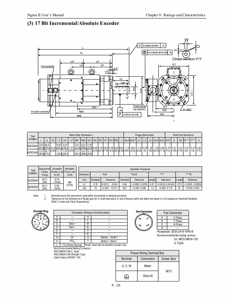
Sigma II User’s Manual Chapter 8: Ratings and Characteristics
8 - 26
(3) 17 Bit Incremental/Absolute Encoder
Note: 1. Dimensio ns are the same wh en using either incremental or absolu te encod ers.2. Toleran ce s on the dimensio ns of fla nge type LB, o f shaft exte nsions S, and of keywa y wid th and dep th are based on JIS (Japane se Industrial Standard)
B040 1 “L imits and Fits fo r Engineerin g.”
Type SGMBH-
Mo tor Body Dimension s Flange Dimen sions Shaft End Dimension
L LL LD L F LN L P KB1 KB2 KG KN KS KT CK1 CK2 J ΦLA ΦLB** LC L E LG ΦLH ΦLZ ΦS* Q QK W**** T** * U
3GD A61 3 2.0(81 4)
26 .5(674 ) 9.2 9
(2 36)
9.45(240 )
5.91(150 ) 7 .87
(20 0)
2 0.1(51 0)
22.0(558)
1 1.6(29 5) 8 .66
(22 0)7.91(201)
6.8 5(1 74)
2.36(6 0)
2.36(60)
8.6 6(2 20)
1 1.8(300 )
9.8 4(2 50)
11.8(3 00)
0.20(5)
1.38(35)
1 3.8(35 0)
0.69(17 .5)
2.76(7 0)
5.51(140)
4.33(110)
0.7 9(20)
0.47(12)
0.29(7.5 )
4ED A61 3 3.7(85 5)
28 .1(715 )
11 .1 (281)
7.87(200 )
2 1.7(55 1)
23.6(599)
13..2(33 6)
KTKS
KN
LC
QQK
ΦS
ΦLA
ΦLB J
LC
4 - ΦLZ
LELG
LNLF
LPLD
LL
L
KG
KB1
KB2
0.0020 (0.05) A
Φ0.0020 (Φ0.05) A
A
0.0012 (0.03)
Fan connector
Encoder connector
Power wiring
W
T
U
Y
Y
Cross-section Y-Y
CK1CK2
ΦLH
Φ2.40 (Φ61)
Type SGMBH-
Approximate Mass lb (kg)
Allowable Ra dial Lo ad
lb (N)
Allo wable Thrust Load
lb (N)
3GD A61 50 7.1(230)
16 74(74 48) 485
(215 6)4ED A61 55 1.1
(250)17 62(78 40)
Specified Tolerances
Dimensio n *ΦS **ΦLB ** *T *** *W
Un it Diame ter Tolerance Diameter Tole ra nce Leng th Tole rance L ength To lerancein 2.76 +0 .001 2 -0.0 04 9 .84 +0.0000 -0.0018 0.47 +0 .00 00 -0 .00 433 0.7 9 +0.0000 -0.00204
mm 70 +0.030 +0.011 25 0 +0.000 -0.046 1 2 +0.000 -0.110 20 +0.0 00 -0 .05 2
A BC
D
MN PT
E
K
G F
J S R
L
H
Encoder Plug Fan Connector
Receptacle: CE05-2A18-10PD-BNon-environmental mating connec-
tor: MS3108B18-10S (L-Type)
Fan ConnectorA U PhaseB V PhaseC W Ph aseD —
A
B
D
C
Power Wiring Terminal BoxTerminal Connection Screw Size
U, V, W MotorM10
Ground
Non -Envi ro nmental Ma tin g C onnector: MS3108B20 -2 9S (L Type)MS3106B20 -2 9S (Stra ight Type)Cab le Clamp: MS3057 -12A
Connector Wiring on the EncodersA — K —B — L —C Data + M —D Data − N —E — P —F — R —G 0V S Battery − (N ote *)H +5 Vd c T Ba ttery + (Note*)J FG (Frame Grou nd) *N ote : Used with an a bsolute encode r only.
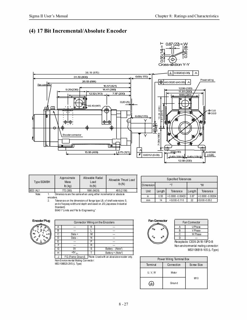
Sigma II User’s Manual Chapter 8: Ratings and Characteristics
8 - 27
(4) 17 Bit Incremental/Absolute Encoder
Fan connector
Power wiring
38.19 (970)
31.50 (800)
26.93 (684)
16.57 (421)
12.32 (313) 7.87 (200)14.41 (366)9.29 (236)
6.69 (170)
12.99 (330)11.81 (300)8.66 (220)
5.49 (139.5)
3.54 (90)15.98 (406) 4.75 (121) 4-Φ0.94
12.99 (330)5.49 (139.5) (Φ24)
6.69 (170)
Φ3.
15(Φ
80)
7.09
(180
)10
.24
(260
)7.
91 (2
01)
0.0020 (0.05) A
Φ0.0020 (Φ0.05) A
A
0.0012 (0.03)
0.87 (22) = W
0.55
(14)
= T
0.35
(9)
Y
Y
Cross-section Y-Y
0.20 (5)
Encoder connector
Φ2.40 (Φ61)
Ι 13.8Ι 350( )
Type SGMBHApproximate
Mass lb (kg)
Allowable RadialLoadlb (N)
Allowable Thrust Loadlb (N)
5ED AL1 772 (350) 1895 (842 8) 48 5 (2 156)Note : 1. Dimensio ns are the same wh en using either incremental or absolu te
encode rs.2. Toleran ce s on the dimension s of fla nge type LB, o f shaft exte nsions S,
an d o f keyway w idth a nd depth are b ased on JIS (Jap anese In dustrial Standard) B040 1 “Limits and Fits fo r Engineerin g.”
Specified Tolerances
Dimension *T *W
Unit Length Tolerance Length Tolerancein 0.55 +0.0000 -0.00433 0.87 +0.0000 -0.00204
mm 14 +0.0 00 -0 .11 0 22 +0.0 00 -0 .05 2
A BC
D
MN PT
E
K
G F
J S R
L
H
Encoder Plug Fan Connector
A
B
D
C
Power Wiring Terminal Box
Terminal Connection Screw Size
U , V, W Moto r
M1 0Groun d
Receptacle: CE05-2A18-10PD-BNon-environmental mating connector:
MS3108B18-10S (L-Type)
Fan ConnectorA U Pha seB V PhaseC W PhaseD —
Non-Environ me ntal Mating Con necto r: MS3 108B20-29 S (L Type)
Connector Wiring on the EncodersA — K —B — L —C Data + M —D Data − N —E — P —F — R —G 0V S Battery − (Note*)H +5V d c T Batte ry + (Note*)J FG (Frame Groun d) *No te: U sed w ith an ab so lute e ncoder only.
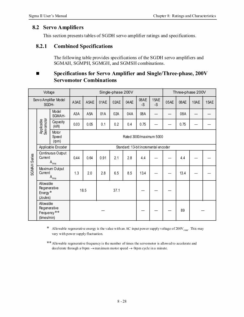
Sigma II User’s Manual Chapter 8: Ratings and Characteristics
8 - 28
8.2 Servo AmplifiersThis section presents tables of SGDH servo amplifier ratings and specifications.
8.2.1 Combined Specifications
The following table provides specifications of the SGDH servo amplifiers and SGMAH, SGMPH, SGMGH, and SGMSH combinations.
Specifications for Servo Amplifier and Single/Three-phase, 200V Servomotor Combinations
* Allowable regenerative energy is the value with an AC input power supply voltage of 200Vrms. This may vary with power supply fluctuation.
**Allowable regenerative frequency is the number of times the servomotor is allowed to accelerate and decelerate through a 0rpm → maximum motor speed → 0rpm cycle in a minute.
Voltage Single-phase 200V Three-phase 200V
Servo Amplifier ModelSGDH- A3AE A5AE 01AE 02AE 04AE 08AE
-S15AE
-S 05AE 08AE 10AE 15AE
SGMA
H Se
ries
Appli
cable
Serv
omot
or
ModelSGMAH- A3A A5A 01A 02A 04A 08A — — 08A — —
Capacity (kW) 0.03 0.05 0.1 0.2 0.4 0.75 — — 0.75 — —
Motor Speed (rpm)
Rated 3000/maximum 5000
Applicable Encoder Standard: 13-bit incremental encoderContinuous Output Current
Arms
0.44 0.64 0.91 2.1 2.8 4.4 — — 4.4 — —
Maximum Output Current
Arms1.3 2.0 2.8 6.5 8.5 13.4 — — 13.4 — —
Allowable Regenerative Energy*(Joules)
18.5 37.1 — — —
Allowable Regenerative Frequency**(t imes/min)
— — — — 89 —
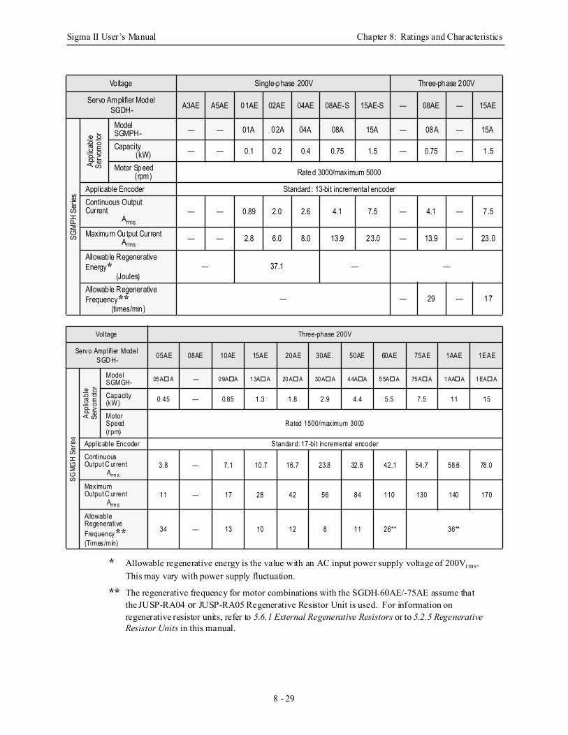
Sigma II User’s Manual Chapter 8: Ratings and Characteristics
8 - 29
* Allowable regenerative energy is the value with an AC input power supply voltage of 200Vrms. This may vary with power supply fluctuation.
** The regenerative frequency for motor combinations with the SGDH-60AE/-75AE assume that
the JUSP-RA04 or JUSP-RA05 Regenerative Resistor Unit is used. For information on regenerative resistor units, refer to 5.6.1 External Regenerative Resistors or to 5.2.5 Regenerative Resistor Units in this manual.
Voltage Single-phase 200V Three-phase 200V
Servo Amplifier ModelSGDH- A3AE A5AE 01AE 02AE 04AE 08AE-S 15AE-S — 08AE — 15AE
SGMP
H Se
ries
Appli
cable
Servo
motor
ModelSGMPH- — — 01A 02A 04A 08A 15A — 08A — 15A
Capacity(kW) — — 0.1 0.2 0.4 0.75 1.5 — 0.75 — 1.5
Motor Speed(rpm) Rated 3000/maximum 5000
Applicable Encoder Standard : 13-bit incrementa l encoderContinuous Output Current
Arms— — 0.89 2.0 2.6 4.1 7.5 — 4.1 — 7.5
Maximum Output CurrentArms
— — 2.8 6.0 8.0 13.9 23.0 — 13.9 — 23.0
Allowab le Regenerative Energy*
(Joules)— 37.1 — —
Allowab le Regenerative Frequency**
(times/min)— — 29 — 17
Voltage Three-phase 200V
Servo Amplifier ModelSGD H- 05AE 08AE 10AE 15AE 20AE 30AE. 50AE 60AE 75AE 1AAE 1EAE
SGMG
H Se
ries
Appli
cabl
eSe
rvom
otor
ModelSGMGH- 05 A A — 0 9A A 1 3A A 20 A A 30 A A 4 4A A 5 5A A 75 A A 1 AA A 1 EA A
Capacity (kW) 0.45 — 0.85 1.3 1.8 2.9 4.4 5.5 7.5 11 15
Motor Speed (rpm)
Rated 1500/maximum 3000
Applicable Encoder Standard: 17-bit incremental encoder
ContinuousOutput C ur rent
Arm s3.8 — 7.1 10.7 16.7 23.8 32.8 42.1 54.7 58.6 78.0
MaximumOutput C ur rent
Arm s11 — 17 28 42 56 84 110 130 140 170
AllowableRegenerative Frequency**(Times/min)
34 — 13 10 12 8 11 26** 36**
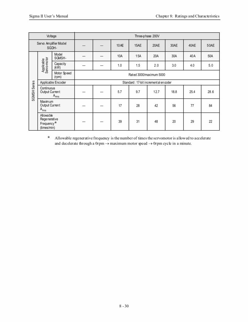
Sigma II User’s Manual Chapter 8: Ratings and Characteristics
8 - 30
* Allowable regenerative frequency is the number of times the servomotor is allowed to accelerate and decelerate through a 0rpm → maximum motor speed → 0rpm cycle in a minute.
Voltage Three-phase 200V
Servo Amplifier ModelSGDH- — — 10AE 15AE 20AE 30AE 40AE 50AE
SGMS
H Se
ries
Appli
cable
Servo
-mot
or
ModelSGMSH- — — 10A 15A 20A 30A 40A 50A
Capacity (kW) — — 1.0 1.5 2 .0 3.0 4.0 5.0
Motor Speed (rpm) Rated 3000/maximum 5000
Applicable Encoder Standard : 17-bit incremental encoderContinuous Output Curren t
Arms— — 5.7 9.7 12.7 18.8 25.4 28.6
Maximum Output Curren tArms
— — 17 28 42 56 77 84
Allowable Regenerative Frequency*(times/min)
— — 39 31 48 20 29 22
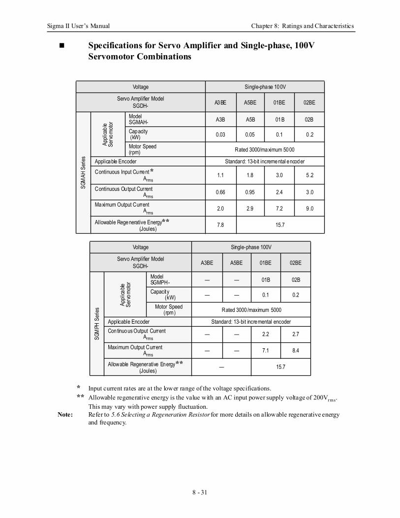
Sigma II User’s Manual Chapter 8: Ratings and Characteristics
8 - 31
Specifications for Servo Amplifier and Single-phase, 100V Servomotor Combinations
* Input current rates are at the lower range of the voltage specifications.** Allowable regenerative energy is the value with an AC input power supply voltage of 200Vrms.
This may vary with power supply fluctuation.Note: Refer to 5.6 Selecting a Regeneration Resistor for more details on allowable regenerative energy
and frequency.
Voltage Single-phase 100V
Servo Amplifier ModelSGDH- A3BE A5BE 01BE 02BE
SGM
AH S
eries
Appli
cable
Servo
motor
ModelSGMAH- A3B A5B 01B 02B
Capacity (kW) 0.03 0.05 0.1 0 .2
Motor Speed(rpm) Rated 3000/maximum 5000
Applicable Encoder Standard: 13-b it incremental encoder
Continuous Input Current *Arms
1.1 1.8 3.0 5 .2
Continuous Output Current Arms
0.66 0.95 2.4 3 .0
Maximum Output CurrentArms
2.0 2.9 7.2 9 .0
Allowable Regenerative Energy**(Joules) 7.8 15.7
Voltage Single-phase 100V
Servo Amplifier ModelSGDH- A3BE A5BE 01BE 02BE
SGM
PH S
eries
Appli
cable
Servo
motor
ModelSGMPH- — — 01B 02B
Capacit y (kW) — — 0.1 0.2
Motor Speed (rpm) Rated 3000/maximum 5000
Applicable Encoder Standard: 13-bit incremental encoderContinuous Output Current
Arms— — 2.2 2.7
Maximum Output CurrentArms
— — 7.1 8.4
Allowable Regenerative Energy**(Joules) — 15.7
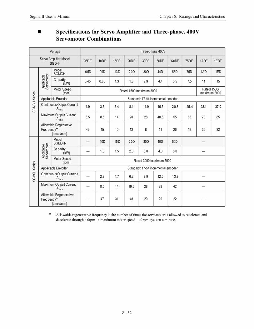
Sigma II User’s Manual Chapter 8: Ratings and Characteristics
8 - 32
Specifications for Servo Amplifier and Three-phase, 400V Servomotor Combinations
* Allowable regenerative frequency is the number of times the servomotor is allowed to accelerate and decelerate through a 0rpm → maximum motor speed → 0rpm cycle in a minute.
Voltage Three-phase 400V
Servo Amplifier ModelSGDH- 05DE 10DE 15DE 20DE 30DE 50DE 60DE 75DE 1ADE 1EDE
SGMG
H Se
ries
Appli
cable
Serv
omoto
r
Mode lSGMGH- 05D 09D 13D 20D 30D 44D 55D 75D 1AD 1ED
Capacity (kW) 0.45 0.85 1.3 1.8 2.9 4.4 5.5 7.5 11 15
Motor Speed (rpm) Rated 1500/maximum 3000 Rated 1500/
maximum 2000App licable Encoder Standard : 17-bit incrementa l encoderContinuous Output Curren t
Arms1.9 3.5 5.4 8.4 11.9 16.5 20.8 25.4 28.1 37.2
Maximum Outpu t CurrentArms
5.5 8.5 14 20 28 40.5 55 65 70 85
Allowable Regenrative Frequency*
(times/min)42 15 10 12 8 11 26 18 36 32
SGMS
H Se
ries
Appli
cable
Servo
moto
r
Mode lSGMSH- — 10D 15D 20D 30D 40D 50D —
Capacity (kW) — 1.0 1.5 2.0 3.0 4.0 5.0 —
Motor Speed (rpm) Rated 3000/maximum 5000
App licable Encoder Standard : 17-bit incrementa l encoderContinuous Output Curren t
Arms— 2.8 4.7 6.2 8.9 12.5 13.8 —
Maximum Outpu t CurrentArms
— 8.5 14 19.5 28 38 42 —
Allowable Regenerative Frequency*
(times/min)— 47 31 48 20 29 22 —
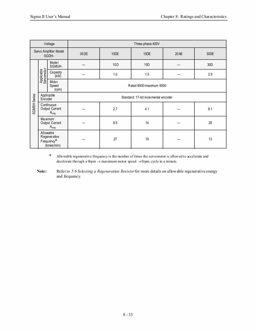
Sigma II User’s Manual Chapter 8: Ratings and Characteristics
8 - 33
* Allowable regenerative frequency is the number of times the servomotor is allowed to accelerate and decelerate through a 0rpm → maximum motor speed → 0rpm cycle in a minute.
Note: Refer to 5.6 Selecting a Regeneration Resistor for more details on allowable regenerative energy and frequency.
Voltage Three-phase 400V
Servo Amplifier ModelSGDH- 05DE 10DE 15DE 20AE 30DE
SGMS
H Se
ries
Appli
cable
Servo
moto
r
Mode lSGMUH- — 10D 15D — 30D
Capacity (kW) — 1.0 1.5 — 2.9
Motor Speed
(rpm)Rated 6000/maximum 6000
Applicable Encoder Standard: 17-bit incremental encoder
Continuous Output Current
Arms— 2.7 4.1 — 8.1
MaximumOutput Current
Arms— 8.5 14 — 28
Allowable Regenerative Frequency*
(times/min)— 27 19 — 13
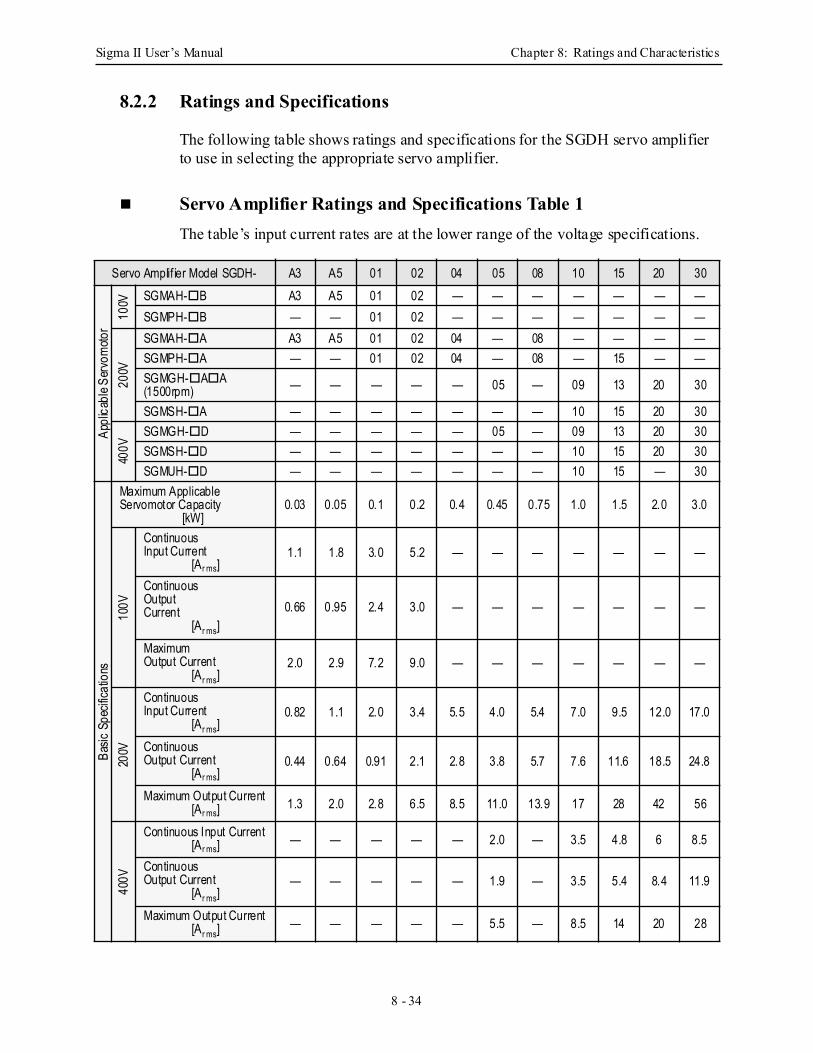
Sigma II User’s Manual Chapter 8: Ratings and Characteristics
8 - 34
8.2.2 Ratings and Specifications
The following table shows ratings and specifications for the SGDH servo amplifier to use in selecting the appropriate servo amplifier.
Servo Amplifier Ratings and Specifications Table 1The table’s input current rates are at the lower range of the voltage specifications.
Servo Amplif ier Model SGDH- A3 A5 01 02 04 05 08 10 15 20 30
Appl
icabl
e Ser
vom
otor
100V SGMAH- B A3 A5 01 02 — — — — — — —
SGMPH- B — — 01 02 — — — — — — —
200V
SGMAH- A A3 A5 01 02 04 — 08 — — — —SGMPH- A — — 01 02 04 — 08 — 15 — —SGMGH- A A (1500rpm) — — — — — 05 — 09 13 20 30
SGMSH- A — — — — — — — 10 15 20 30
400V
SGMGH- D — — — — — 05 — 09 13 20 30SGMSH- D — — — — — — — 10 15 20 30SGMUH- D — — — — — — — 10 15 — 30
Basic
Spe
cifica
tions
Maximum ApplicableServomotor Capacity
[kW]0.03 0.05 0.1 0.2 0.4 0.45 0.75 1.0 1.5 2.0 3.0
100V
ContinuousInput Current
[Ar ms]1.1 1.8 3.0 5.2 — — — — — — —
ContinuousOutputCurrent
[Ar ms]0.66 0.95 2.4 3.0 — — — — — — —
MaximumOutput Current
[Ar ms]2.0 2.9 7.2 9.0 — — — — — — —
200V
ContinuousInput Current
[Ar ms]0.82 1.1 2.0 3.4 5.5 4.0 5.4 7.0 9.5 12.0 17.0
Continuous Output Current
[Ar ms]0.44 0.64 0.91 2.1 2.8 3.8 5.7 7.6 11.6 18.5 24.8
Maximum Output Current[Ar ms] 1.3 2.0 2.8 6.5 8.5 11.0 13.9 17 28 42 56
400V
Continuous Input Current[Ar ms] — — — — — 2.0 — 3.5 4.8 6 8.5
Continuous Output Current
[Ar ms]— — — — — 1.9 — 3.5 5.4 8.4 11.9
Maximum Output Current[Ar ms]
— — — — — 5.5 — 8.5 14 20 28
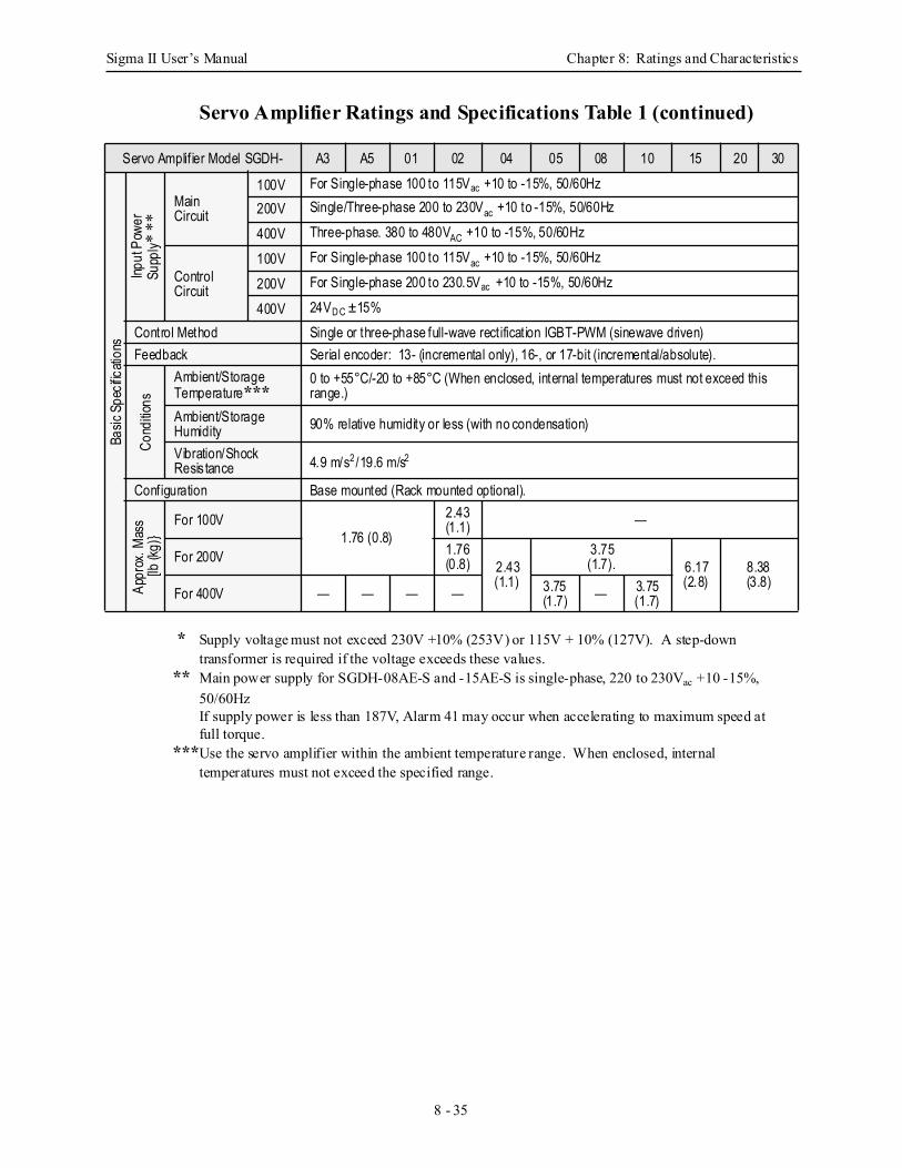
Sigma II User’s Manual Chapter 8: Ratings and Characteristics
8 - 35
Servo Amplifier Ratings and Specifications Table 1 (continued)
* Supply voltage must not exceed 230V +10% (253V) or 115V + 10% (127V). A step-down transformer is required if the voltage exceeds these values.
** Main power supply for SGDH-08AE-S and -15AE-S is single-phase, 220 to 230Vac +10 -15%, 50/60HzIf supply power is less than 187V, Alarm 41 may occur when accelerating to maximum speed at full torque.
***Use the servo amplifier within the ambient temperature range. When enclosed, internal temperatures must not exceed the specified range.
Servo Amplif ier Model SGDH- A3 A5 01 02 04 05 08 10 15 20 30
Basic
Spe
cifica
tions
Input
Pow
erSu
pply*
**
MainCircuit
100V For Single-phase 100 to 115Vac +10 to -15%, 50/60Hz200V Single/Three-phase 200 to 230Vac +10 to -15%, 50/60Hz
400V Three-phase. 380 to 480VAC +10 to -15%, 50/60Hz
ControlCircuit
100V For Single-phase 100 to 115Vac +10 to -15%, 50/60Hz
200V For Single-phase 200 to 230.5Vac +10 to -15%, 50/60Hz
400V 24VD C ±15%Control Method Single or three-phase full-wave rectification IGBT-PWM (sinewave driven)Feedback Serial encoder: 13- (incremental only), 16-, or 17-bit (incremental/absolute).
Cond
itions
Ambient/StorageTemperature***
0 to +55°C/-20 to +85°C (When enclosed, internal temperatures must not exceed this range.)
Ambient/StorageHumidity 90% relative humidity or less (with no condensation)
Vibration/ShockResis tance 4.9 m/s2/19.6 m/s2
Configuration Base mounted (Rack mounted optional).
Appr
ox. M
ass
[lb (k
g)
For 100V1.76 (0.8)
2.43(1.1) —
For 200V 1.76 (0.8) 2.43
(1.1)
3.75(1.7). 6.17
(2.8)8.38(3.8)
For 400V — — — — 3.75(1.7) — 3.75
(1.7)
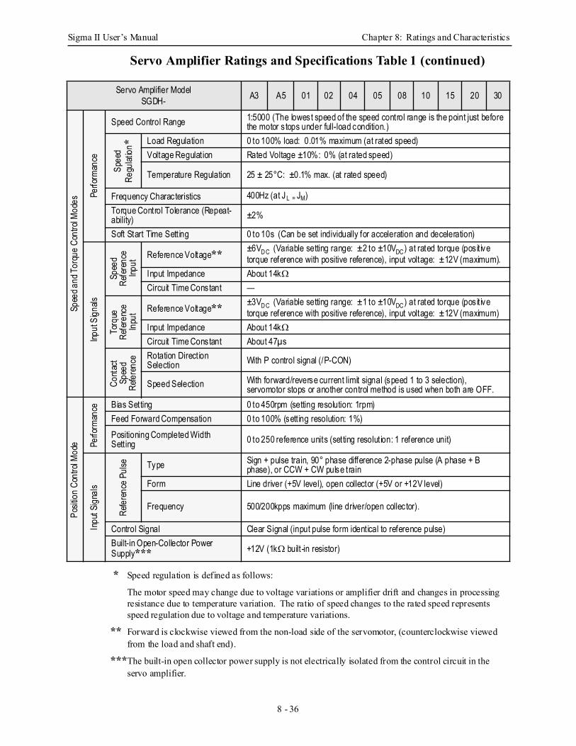
Sigma II User’s Manual Chapter 8: Ratings and Characteristics
8 - 36
Servo Amplifier Ratings and Specifications Table 1 (continued)
* Speed regulation is defined as follows:
The motor speed may change due to voltage variations or amplifier drift and changes in processing resistance due to temperature variation. The ratio of speed changes to the rated speed represents speed regulation due to voltage and temperature variations.
** Forward is clockwise viewed from the non-load side of the servomotor, (counterclockwise viewed from the load and shaft end).
***The built-in open collector power supply is not electrically isolated from the control circuit in the servo amplifier.
Servo Amplifier ModelSGDH- A3 A5 01 02 04 05 08 10 15 20 30
Spee
d and
Tor
que
Cont
rol M
odes
Perfo
rman
ce
Speed Control Range 1:5000 (The lowest speed of the speed control range is the point just before the motor s tops under full-load condition.)
Spee
dRe
gulat
ion* Load Regulation 0 to 100% load: 0.01% maximum (at rated speed)
Voltage Regulation Rated Voltage ±10%: 0% (at rated speed)
Temperature Regulation 25 ± 25°C: ±0.1% max. (at rated speed)
Frequency Characteristics 400Hz (at JL = JM)Torque Control Tolerance (Repeat-ability) ±2%
Soft Start Time Sett ing 0 to 10s (Can be set individually for acceleration and deceleration)
Input
Sign
als
Spee
dRe
fere
nce
Input
Reference Voltage** ±6VD C (Variable setting range: ±2 to ±10VDC) at rated torque (pos it ive torque reference with positive reference), input voltage: ±12V (maximum).
Input Impedance About 14kΩCircuit Time Constant —
Torq
ueRe
fere
nce
Inpu
t Reference Voltage** ±3VD C (Variable setting range: ±1 to ±10VDC) at rated torque (pos it ive torque reference with positive reference), input voltage: ±12V (maximum)
Input Impedance About 14kΩCircuit Time Constant About 47µs
Cont
act
Spee
dRe
fere
nce Rotation Direction
Selection With P control signal (/P-CON)
Speed Selection With forward/reverse current limit signal (speed 1 to 3 selection), servomotor stops or another control method is used when both are OFF.
Posit
ion
Cont
rol M
ode Pe
rform
ance Bias Setting 0 to 450rpm (setting resolution: 1rpm)
Feed Forward Compensation 0 to 100% (sett ing resolution: 1%)Positioning Completed WidthSett ing 0 to 250 reference units (setting resolution: 1 reference unit)
Inpu
t Sig
nals
Refe
renc
e Pu
lse Type Sign + pulse train, 90° phase difference 2-phase pulse (A phase + B phase), or CCW + CW pulse train
Form Line driver (+5V level), open collector (+5V or +12V level)
Frequency 500/200kpps maximum (line driver/open collector).
Control Signal Clear Signal (input pulse form identical to reference pulse)Built-in Open-Collector PowerSupply*** +12V (1kΩ built-in resistor)
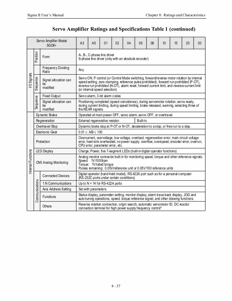
Sigma II User’s Manual Chapter 8: Ratings and Characteristics
8 - 37
Servo Amplifier Ratings and Specifications Table 1 (continued)
Servo Amplifier ModelSGDH- A3 A5 01 02 04 05 08 10 15 20 30
I/O S
ignals
Posit
ion
Form A-, B-, C-phase line driverS-phase line driver (only with an absolute encoder)
Frequency Dividing Ratio Any
Sequ
ence Signal allocation can
bemodified
Servo ON, P control (or Control Mode switching, forward/reverse motor rotation by internal speed sett ing, zero clamping, reference pulse prohibited), forward run prohibited (P-OT), reverse run prohibited (N-OT), alarm reset, forward current limit, and reverse current limit (or internal speed selection)
Sequ
ence Fixed Output Servo alarm, 3-bit alarm codes
Signal allocation can bemodified
Positioning completed (speed coincidence), during servomotor rotation, servo ready, during current limiting, during speed limiting, brake released, warning, selecting three of the NEAR s ignals.
Inte
rnal
Fun
ction
s
Dynamic Brake Operated at main power OFF, servo alarm, servo OFF, or overtravel.Regeneration External regenerative resistor. Built-in.Overtravel Stop Dynamic brake stop at P-OT or N-OT, deceleration to a s top, or free run to a stop.Electronic Gear 0.01 ≤ A/B ≤ 100
ProtectionOvercurrent, overvoltage, low voltage, overload, regeneration error, main circuit voltage error, heat sink overheated, no power supply, overflow, overspeed, encoder error, overrun, CPU error, parameter error, etc.
LED Display Charge, Power, five 7-segment LEDs (built-in digital operator functions)
CN5 Analog MonitoringAnalog monitor connector built in for monitoring speed, torque and other reference signals.Speed: 1V/1000rpmTorque: 1V/rated torquePulses remaining: 0.05V/reference unit or 0.05V/100 reference units
Com
mun
icatio
ns
Connected Devices Digital operator (hand-held model), RS-422A port such as for a personal computer (RS-232C ports under certain conditions)
1:N Communications Up to N = 14 for RS-422A portsAxis Address Sett ing Set with parameters.
Functions Status display, parameter setting, monitor display, alarm trace-back display, JOG and auto-tuning operations, speed, torque reference signal, and other drawing functions.
Others Reverse rotation connection, origin search, automatic servomotor ID, DC reactor connection terminal for high power supply frequency control*
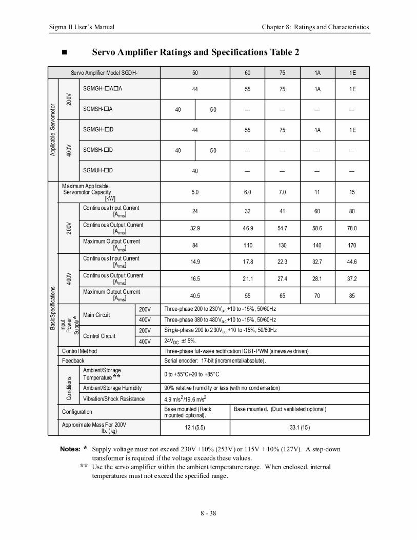
Sigma II User’s Manual Chapter 8: Ratings and Characteristics
8 - 38
Servo Amplifier Ratings and Specifications Table 2
Notes: * Supply voltage must not exceed 230V +10% (253V) or 115V + 10% (127V). A step-down transformer is required if the voltage exceeds these values.
** Use the servo amplifier within the ambient temperature range. When enclosed, internal temperatures must not exceed the specified range.
Servo Amplifier Model SGDH- 50 60 75 1A 1E
Appli
cable
Serv
omot
or 200V
SGMGH- A A 44 55 75 1A 1E
SGMSH- A 40 50 — — — —
400V
SGMGH- D 44 55 75 1A 1E
SGMSH- D 40 50 — — — —
SGMUH- D 40 — — — —
Basic
Spec
ificati
ons
Maximum App licable. Servomotor Capacity
[kW]5.0 6.0 7.0 11 15
200V
Continuous Input Current[Arms] 24 32 41 60 80
Continuous Outpu t Current[Arms] 32.9 46.9 54.7 58.6 78.0
Maximum Output Current[Arms] 84 110 130 140 170
400V
Continuous Input Current[Arms] 14.9 17.8 22.3 32.7 44.6
Continuous Outpu t Current[Arms] 16.5 21.1 27.4 28.1 37.2
Maximum Output Current[Arms] 40.5 55 65 70 85
Input
Powe
rSu
pply *
Main Circuit200V Three-phase 200 to 230Va c +10 to -15%, 50/60Hz
400V Three-phase 380 to 480Va c +10 to -15%, 50/60Hz
Control Circuit200V Single-phase 200 to 230Vac +10 to -15%, 50/60Hz
400V 24VDC ±15%.Contro l Method Three-phase full-wave rectification IGBT-PWM (sinewave driven)Feedback Serial encoder: 17-bit (incremental/abso lute).
Cond
itions
Ambient/Storage Temperature** 0 to +55°C/-20 to +85°C
Ambient/Storage Humidity 90% relative humid ity or less (with no condensation)
Vibration/Shock Resistance 4.9 m/s2/19 .6 m/s2
Configuration Base mounted (Rack mounted optional).
Base mounted. (Duct ventilated optional)
Approximate Mass For 200Vlb. (kg) 12.1(5.5) 33.1 (15)
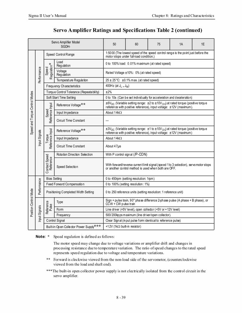
Sigma II User’s Manual Chapter 8: Ratings and Characteristics
8 - 39
Servo Amplifier Ratings and Specifications Table 2 (continued)
Note: * Speed regulation is defined as follows:
The motor speed may change due to voltage variations or amplifier drift and changes in processing resistance due to temperature variation. The ratio of speed changes to the rated speed represents speed regulation due to voltage and temperature variations.
** Forward is clockwise viewed from the non-load side of the servomotor, (counterclockwise viewed from the load and shaft end).
***The built-in open collector power supply is not electrically isolated from the control circuit in the servo amplifier.
Servo Amplifier ModelSGDH- 50 60 75 1A 1E
Spee
d and
Torq
ue C
ontro
l Mod
es
Perfo
rman
ce
Speed Control Range 1:5000 (The lowest speed of the speed control range is the po int just before the motor stops under full-load condition.)
Spee
dRe
gulat
ion* Load
Regulation 0 to 100% load: 0 .01% maximum (at rated speed)
Voltage Regulation Rated Voltage ±10%: 0% (at rated speed)
Temperature Regula tion 25 ± 25°C: ±0.1% max. (at rated speed)Frequency Characteristics 400Hz (at JL = JM)
Torque Control Tolerance (Repeatability) ±2%Soft Start Time Set ting 0 to 10s (Can be se t individually for acceleration and deceleration)
Input
Sign
als
Spee
dRe
feren
ce In
put
Refe rence Voltage** ±6VDC (Variable setting range: ±2 to ±10V D C) at rated torque (positive torque reference with positive reference), input voltage: ±12V (maximum).
Input Impedance About 14kΩ
Circuit Time Constant —
Torqu
eRe
feren
ce In
put
Refe rence Voltage** ±3VDC (Variable setting range: ±1 to ±10V D C) at rated torque (positive torque reference with positive reference), input voltage: ±12V (maximum)
Input Impedance About 14kΩ
Circuit Time Constant About 47µs
Conta
ct Sp
eed
Refer
ence
Rota tion Direction Selection With P control signal (/P-CON)
Speed Selection With forward/reverse curren t limit signal (speed 1 to 3 selection), servomotor stops or another control method is used when both are OFF.
Posit
ion C
ontro
l Mod
e
Perfo
rman
ce Bias Setting 0 to 450rpm (setting resolution: 1rpm)Feed Forward Compensation 0 to 100% (setting resolution : 1%)
Positioning Completed Width Setting 0 to 250 refe rence units (setting resolution: 1 reference unit)
Input
Sign
als
Refer
ence
Pulse
Type Sign + pu lse tra in, 90° phase difference 2-phase pulse (A phase + B phase), or CCW + CW pulse train
Form Line driver (+5V level), open collecto r (+5V or +12V level)Frequency 500/200kpps maximum (line driver/open collector).
Control Signal Clear Signal (input pulse form identical to reference pulse)
Built-in Open Collector Power Supply*** +12V (1kΩ built-in resistor)
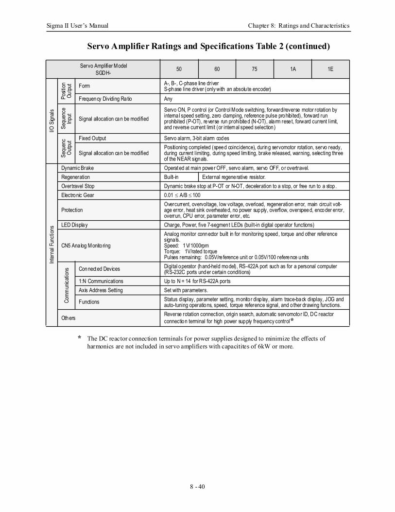
Sigma II User’s Manual Chapter 8: Ratings and Characteristics
8 - 40
Servo Amplifier Ratings and Specifications Table 2 (continued)
* The DC reactor connection terminals for power supplies designed to minimize the effects of harmonics are not included in servo amplifiers with capacitites of 6kW or more.
Servo Amplifier ModelSGDH- 50 60 75 1A 1E
I/O S
ignals
Posit
ionOu
tput Form A-, B-, C-phase line driver
S-phase line driver (only with an absolu te encoder)Frequency Dividing Ratio Any
Sequ
ence
Input Signal allocation can be modified
Servo ON, P control (or Control Mode switching, forward/reverse motor rotation by interna l speed setting, zero clamping, reference pulse prohibited), forward run prohibited (P-OT), reverse run prohibited (N-OT), ala rm rese t, forward current limit, and reverse current limit (or internal speed selection)
Sequ
enc
Outp
ut
Fixed Output Servo alarm, 3-bit alarm codes
Signal allocation can be modifiedPositioning completed (speed coincidence), during servomotor rotation, servo ready, during current limiting, during speed limiting, brake released, warning, selecting three of the NEAR signals.
Inter
nal F
uncti
ons
Dynamic Brake Operated at main power OFF, servo alarm, servo OFF, o r overtravel.Regeneration Built-in External regenerative resistor.Overtravel Stop Dynamic brake stop at P-OT or N-OT, deceleration to a stop, or free run to a stop .Electronic Gear 0.01 ≤ A/B ≤ 100
ProtectionOvercurrent, overvoltage, low voltage, overload, regeneration error, main circuit volt-age error, heat sink overheated, no power supply, overflow, overspeed, encoder error, overrun, CPU error, parameter error, etc.
LED Display Charge, Power, five 7-segment LEDs (built-in digital operator functions)
CN5 Ana log Monito ring
Analog monitor connector built in for monitoring speed, torque and other referencesigna ls.Speed: 1V/1000rpmTorque: 1V/rated to rquePulses remaining: 0.05V/re ference unit or 0.05V/100 reference units
Comm
unica
tions Connected Devices Digital operator (hand-held model), RS-422A port such as for a personal computer
(RS-232C ports under certain conditions)1:N Communications Up to N = 14 for RS-422A portsAxis Address Setting Set with parameters.
Functions Status display, parameter setting, monito r disp lay, alarm trace-back display, JOG and auto-tuning operations, speed, torque reference signal, and o ther drawing functions.
Others Reverse rotation connection, origin search, automatic servomotor ID, DC reactor connection terminal for high power supply frequency control*
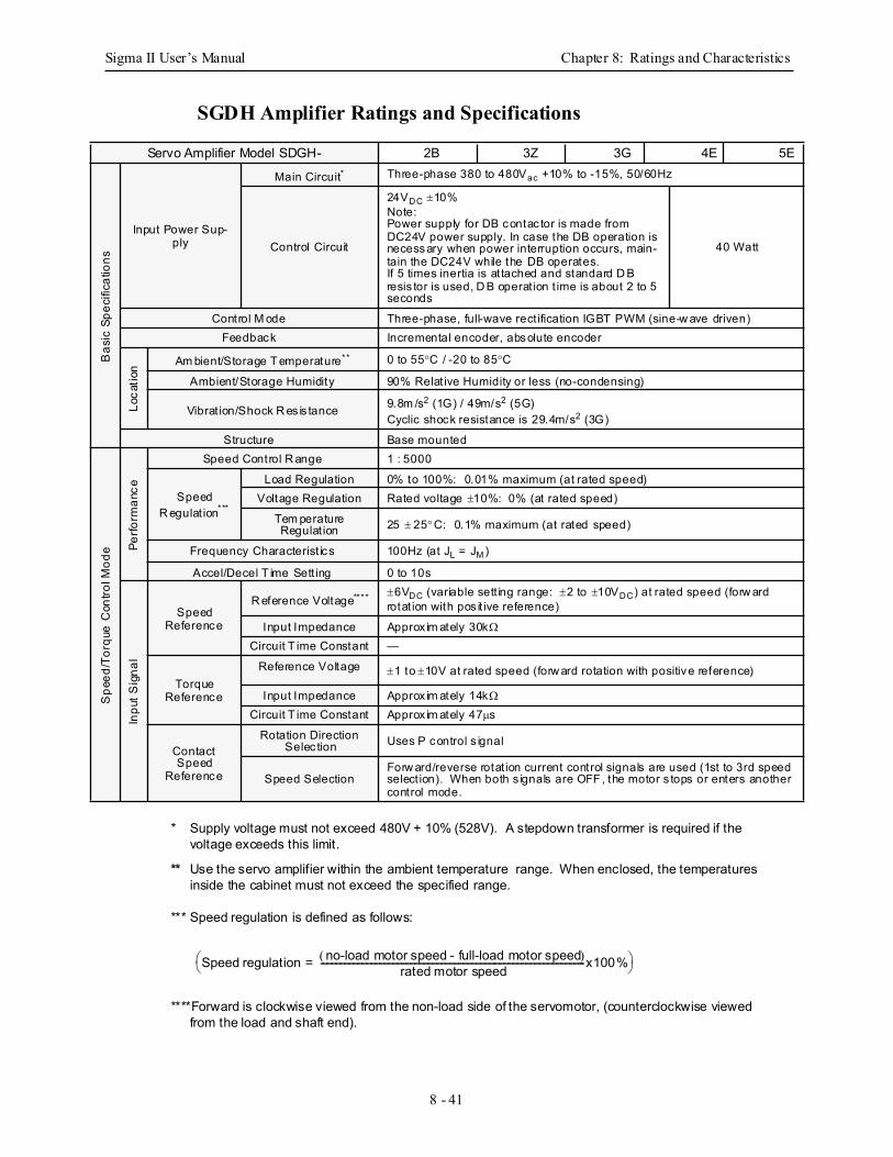
Sigma II User’s Manual Chapter 8: Ratings and Characteristics
8 - 41
SGDH Amplifier Ratings and Specifications
* Supply voltage must not exceed 480V + 10% (528V). A stepdown transformer is required if the voltage exceeds this limit.
** Use the servo amplifier within the ambient temperature range. When enclosed, the temperatures inside the cabinet must not exceed the specified range.
*** Speed regulation is defined as follows:
****Forward is clockwise viewed from the non-load side of the servomotor, (counterclockwise viewed from the load and shaft end).
Servo Amplifier Model SDGH- 2B 3Z 3G 4E 5E
Bas
ic S
peci
ficat
ions
Input Power Sup-ply
Main Circuit* Three-phase 380 to 480Vac +10% to -15%, 50/60Hz
Control Circuit
24VDC ±10% Note:Power supply for DB contac tor is made from DC24V power supply. In case the DB operation is necessary when power interruption occurs, main-tain the DC24V while the DB operates.If 5 times inertia is at tached and standard D B resis tor is used, D B operat ion t ime is about 2 to 5 seconds
40 Watt
Control M ode Three-phase, full-wave rect ification IGBT PWM (sine-w ave driven)Feedback Incremental encoder, absolute encoder
Loca
tion Am bient/Storage T emperature** 0 to 55°C / -20 to 85°C
Ambient/Storage Humidity 90% Relat ive Humidity or less (no-condensing)
Vibrat ion/Shock R es is tance 9.8m /s2 (1G) / 49m/s2 (5G) Cyclic shock resistance is 29.4m/s2 (3G)
Structure Base mounted
Spe
ed/T
orqu
e C
ontro
l Mod
e Perfo
rman
ce
Speed Control R ange 1 : 5000
SpeedR egulat ion***
Load Regulation 0% to 100%: 0.01% maximum (at rated speed)Voltage Regulation Rated voltage ±10%: 0% (at rated speed)
Tem peratureRegulat ion 25 ± 25°C: 0.1% maximum (at rated speed)
Frequency Characterist ics 100Hz (at JL = JM )
Accel/Decel T ime Sett ing 0 to 10s
Inpu
t Sig
nal
SpeedReference
R eference Voltage**** ±6VDC (variable sett ing range: ±2 to ±10VDC) at rated speed (forw ard rotat ion with pos it ive reference)
Input Impedance Approx im ately 30kΩ
Circuit T ime Constant —
TorqueReference
Reference Voltage ±1 to ±10V at rated speed (forw ard rotation with positive reference)
Input Impedance Approx im ately 14kΩ
Circuit T ime Constant Approx im ately 47µs
Contact Speed
Reference
Rotation Direction Selec tion Uses P control s ignal
Speed SelectionForw ard/reverse rotat ion current control signals are used (1st to 3rd speed select ion). When both s ignals are OFF , the motor s tops or enters another control mode.
Speed regulation no-load motor speed - full-load motor speed( )rated motor speed-------------------------------------------------------------------------------------------------------------------------x100%=
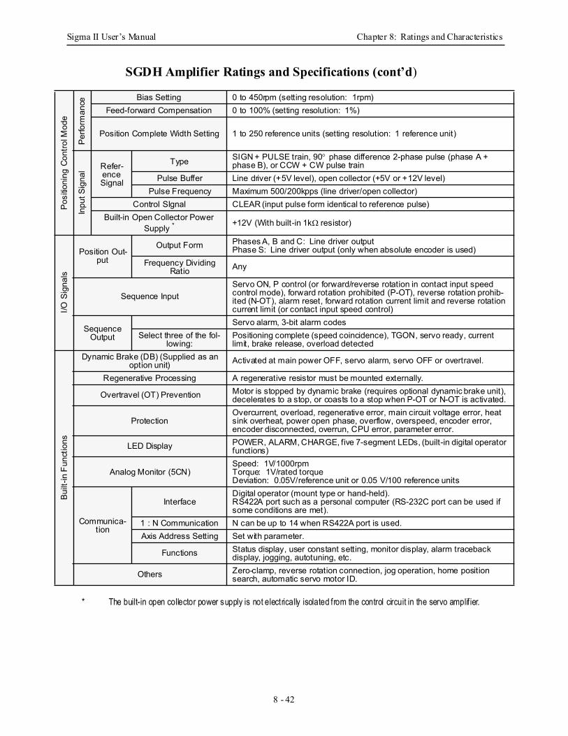
Sigma II User’s Manual Chapter 8: Ratings and Characteristics
8 - 42
SGDH Amplifier Ratings and Specifications (cont’d)
* The built-in open collector power supply is not electrically isolated from the control circuit in the servo amplif ier.
Posi
tioni
ng C
ontro
l Mod
e
Perfo
rman
ce Bias Setting 0 to 450rpm (setting resolution: 1rpm)Feed-forward Compensation 0 to 100% (setting resolution: 1%)
Position Complete Width Setting 1 to 250 reference units (setting resolution: 1 reference unit)
Inpu
t Sig
nal Refer-
ence Signal
Type SIGN + PULSE train, 90° phase difference 2-phase pulse (phase A + phase B), or CCW + CW pulse train
Pulse Buffer Line driver (+5V level), open collector (+5V or +12V level)Pulse Frequency Maximum 500/200kpps (line driver/open collector)
Control SIgnal CLEAR (input pulse form identical to reference pulse)Built-in Open Collector Power
Supply * +12V (With built-in 1kΩ resistor)
I/O S
igna
ls
Position Out-put
Output Form Phases A, B and C: Line driver outputPhase S: Line driver output (only when absolute encoder is used)
Frequency Dividing Ratio Any
Sequence InputServo ON, P control (or forward/reverse rotation in contact input speed control mode), forward rotation prohibited (P-OT), reverse rotation prohib-ited (N-OT), alarm reset, forward rotation current limit and reverse rotation current limit (or contact input speed control)
Sequence Output
Servo alarm, 3-bit alarm codesSelect three of the fol-
lowing:Positioning complete (speed coincidence), TGON, servo ready, current limit, brake release, overload detected
Built
-in F
unct
ions
Dynamic Brake (DB) (Supplied as an option unit) Activated at main power OFF, servo alarm, servo OFF or overtravel.
Regenerative Processing A regenerative resistor must be mounted externally.
Overtravel (OT) Prevention Motor is stopped by dynamic brake (requires optional dynamic brake unit), decelerates to a stop, or coasts to a stop when P-OT or N-OT is activated.
ProtectionOvercurrent, overload, regenerative error, main circuit voltage error, heat sink overheat, power open phase, overflow, overspeed, encoder error, encoder disconnected, overrun, CPU error, parameter error.
LED Display POWER, ALARM, CHARGE, five 7-segment LEDs, (built-in digital operator functions)
Analog Monitor (5CN)Speed: 1V/1000rpmTorque: 1V/rated torqueDeviation: 0.05V/reference unit or 0.05 V/100 reference units
Communica-tion
InterfaceDigital operator (mount type or hand-held).RS422A port such as a personal computer (RS-232C port can be used if some conditions are met).
1 : N Communication N can be up to 14 when RS422A port is used.Axis Address Setting Set with parameter.
Functions Status display, user constant setting, monitor display, alarm traceback display, jogging, autotuning, etc.
Others Zero-clamp, reverse rotation connection, jog operation, home position search, automatic servo motor ID.
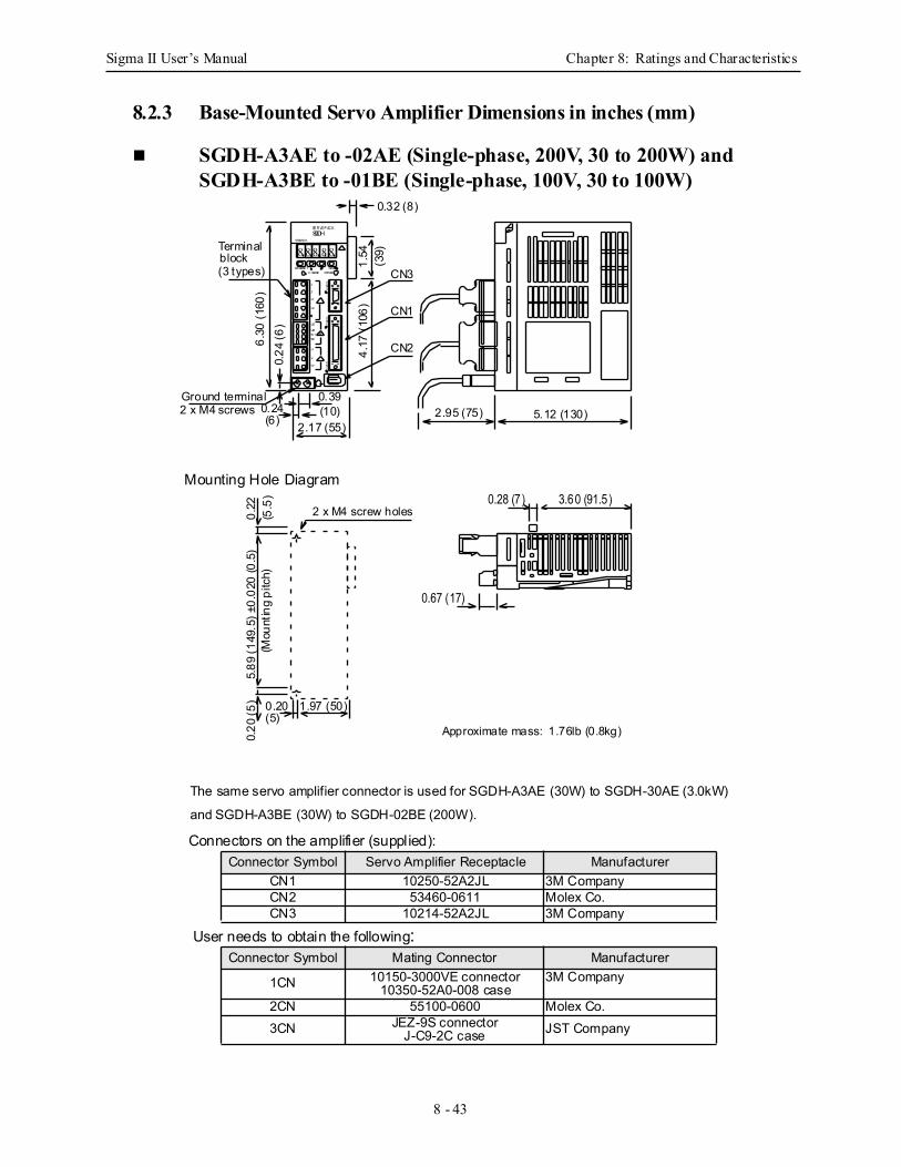
Sigma II User’s Manual Chapter 8: Ratings and Characteristics
8 - 43
8.2.3 Base-Mounted Servo Amplifier Dimensions in inches (mm)
SGDH-A3AE to -02AE (Single-phase, 200V, 30 to 200W) andSGDH-A3BE to -01BE (Single-phase, 100V, 30 to 100W)
8 8 8 88
CN3
CN1
CN2
L1
L2
⊕2
⊕1
L1C
L2C
B2B 1
U
V
W
MODE/SE TC HARGE
DATA/POWER
YASKAWA
SE R VOP AC KSGDH
Terminalblock(3 types) CN3
CN1
CN26.30
(160
)0.
24 (6
)
5.12 (130)2.95 (75)
0.67 (17)
2 x M4 screw holes
2.17 (55)2 x M4 screws 0.24Ground terminal 0.39
(10)
Mounting Hole Diagram
0.22
5.89
(149
.5) ±
0.02
0 (0
.5)
(Mou
ntin
g pi
tch)
0.20
0.20
(5)
Approximate mass: 1.76lb (0.8kg)
The same servo amplifier connector is used for SGDH-A3AE (30W) to SGDH-30AE (3.0kW)
and SGDH-A3BE (30W) to SGDH-02BE (200W).
1.97 (50)
0.32 (8)
(5)
(6)
(5.5
) 0.28 (7 ) 3.60 (91.5 )
4.17
(106
)1.
54(3
9)
Connectors on the amplifier (supplied):
User needs to obtain the following:
Connector Symbol Servo Amplifier Receptacle ManufacturerCN1 10250-52A2JL 3M CompanyCN2 53460-0611 Molex Co.CN3 10214-52A2JL 3M Company
Connector Symbol Mating Connector Manufacturer
1CN 10150-3000VE connector10350-52A0-008 case
3M Company
2CN 55100-0600 Molex Co.3CN JEZ-9S connector
J-C9-2C case JST Company
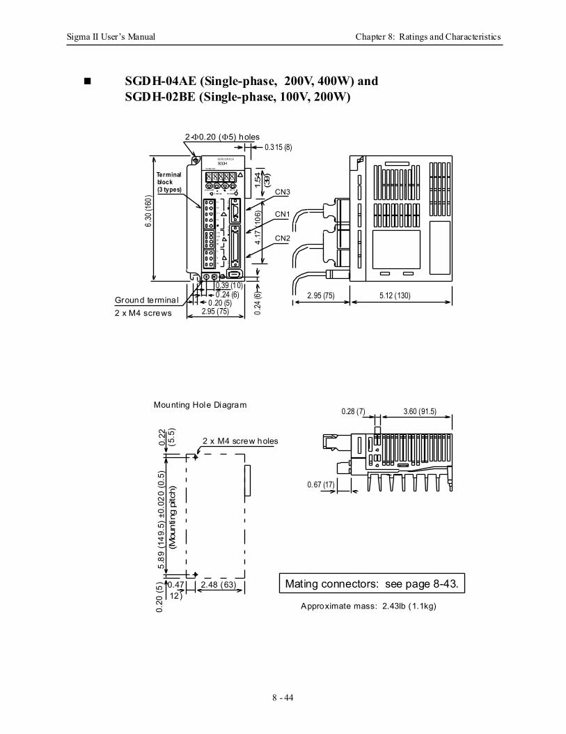
Sigma II User’s Manual Chapter 8: Ratings and Characteristics
8 - 44
SGDH-04AE (Single-phase, 200V, 400W) andSGDH-02BE (Single-phase, 100V, 200W)
8 88 88
CN3
CN1
CN2
L1
L2
⊕2
⊕ 1
L1C
L2C
B2
B1
U
V
W
MOD E/ SET
C HAR GE
DAT A/
POWER
YA SKA WA
S E R V OP A C KSGDH
5.12 (130)2.95 (75)
2.95 (75) 0.24
(6)0 .24 (6)
0.39 (10)
0 .20 (5)Ground terminal2 x M4 screws
6.30
(160
)2-Φ0.20 (Φ5) holes
Terminalblock(3 types)
Mounting Hole Diagram
0.22 2 x M4 screw holes
0.67 (17)
5.89
(149
.5) ±
0.02
0 (0
.5)
(Mou
ntin
g pi
tch)
2.48 (63)0.47
0.20
(5)
Approximate mass: 2.43lb (1.1kg)
0.315 (8)
12)
(5.5
)
CN3
CN1
CN2
0.28 (7) 3.60 (91.5)
4.17
(106
)1.
54(3
9)
Mating connectors: see page 8-43.
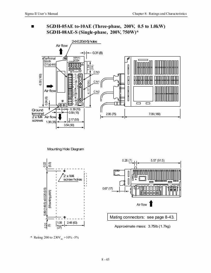
Sigma II User’s Manual Chapter 8: Ratings and Characteristics
8 - 45
SGDH-05AE to-10AE (Three-phase, 200V, 0.5 to 1.0kW)SGDH-08AE-S (Single-phase, 200V, 750W)*
* Rating 200 to 230Vac +10% -5%
8 8 8 88
CN3
CN1
CN2
L1
L2
⊕2
⊕1
L1CL2C
B2B1
UV
W
MODE/SETCHARGE
DATA/POWER
YASKAWA
SERVOSGDH
3.54 (90)
7.09 (180)
1.06
0.39 (10)
1.38 (35)
2.95 (75)Ground
2 x M4
0.24 (
6)
6.30 (
160)
Terminalblock(3 types)
L3
B3
Air flow
0.59 (15)Air flow
2.17 (55)
Air flow
0.67 (17)
Mounting Hole Diagram
0.22
2 x M4screw holes
5.89 (
149.5
) ±0.0
20 (0
.5)(M
ounti
ng pi
tch)
2.48 (63)
0.20
Approximate mass: 3.75lb (1.7kg)
Air flow
0.31 (8)
2-Φ0.20 (Φ5) holes
(5.5)
(27)(5)
terminal
screws
C N3
C N1
C N2
0.28 (7) 5.57 (91.5)
4.17
(10
6)1.
54(3
9)
Mating connectors: see page 8-43.
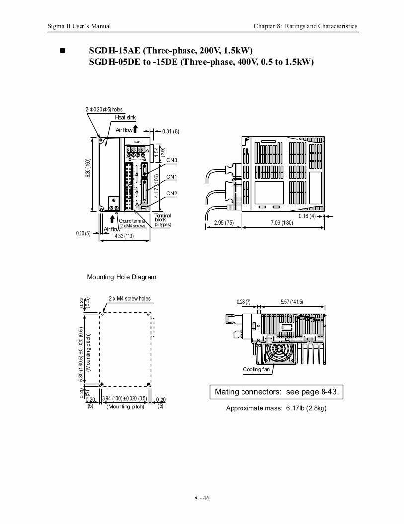
Sigma II User’s Manual Chapter 8: Ratings and Characteristics
8 - 46
SGDH-15AE (Three-phase, 200V, 1.5kW)SGDH-05DE to -15DE (Three-phase, 400V, 0.5 to 1.5kW)
8 8 8 88
CN3
CN1
CN2
L1
L2
⊕ 2
⊕1
L1CL2C
B 2B1
U
V
W
MODE/SE TCHA RGE
DATA/POWER
YASKAWASGDH
7.09 (180)2.95 (75)
0.20 (5) 4.33 (110)
2 x M4 screws
Terminalblock(3 types)
6.30 (
160)
Air flow
Air flow
Heat sink2-Φ0.20 (Φ5) holes
Mounting Hole Diagram
0.22 2 x M4 screw holes
5.89 (
149.5
) ±0.
020 (
0.5)
(Mou
ntin
g pi
tch)
0.20(Mounting pitch)
3.94 (100) ±0.020 (0.5)
Cooling fan
Approximate mass: 6.17lb (2.8kg)
0.16 (4)
(5)
5.57 (141.5)0.28 (7)
0.31 (8)
0 .20(5)
(5.5
)
Ground terminal
0.20 (5)
CN3
CN1
CN24.17
(106
)1.
54(3
9)
Mating connectors: see page 8-43.
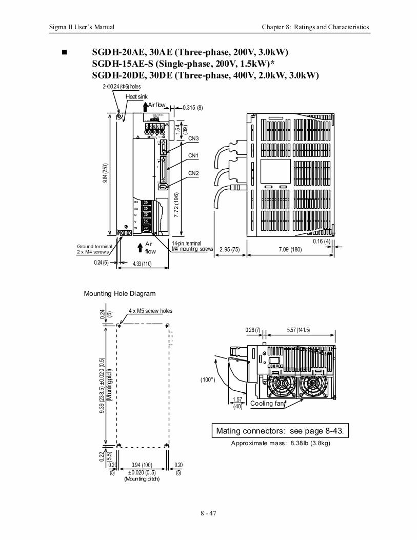
Sigma II User’s Manual Chapter 8: Ratings and Characteristics
8 - 47
SGDH-20AE, 30AE (Three-phase, 200V, 3.0kW)SGDH-15AE-S (Single-phase, 200V, 1.5kW)*SGDH-20DE, 30DE (Three-phase, 400V, 2.0kW, 3.0kW)
8 8 8 88
C N3
C N1
C N2
MODE/ SE T
C HAR GE
D ATA/
POWER
YA SKA WA
S ER V OPA C KSGDH
7.09 (180)2.95 (75)
Mounting Hole Diagram
0.24 4 x M5 screw holes
9.39 (
238.5
) ±0.0
20 (0
.5)(M
ounti
ng pi
tch)
0.22
±0.020 (0 .5)(Mounting pitch)
Cooling fan
Approximate mass: 8.38 lb (3.8kg)
0.16 (4)
(100°)
1.57
Heat sinkAir flow
2-Φ0.24 (Φ6) holes
9.84 (
250)
B2
B3
U
V
W
Airflow
0.24 (6)
M4 mounting screws
4.33 (110)
Ground terminal2 x M4 screws
5.57 (141.5)0.28 (7)
0.315 (8)
14-pin terminal
3.94 (100)
(6)
0.20(5)
(40)
(5.5)
0.20(5)
CN3
CN1
CN27.
72 (1
96)
1.54
(39)
Mating connectors: see page 8-43.
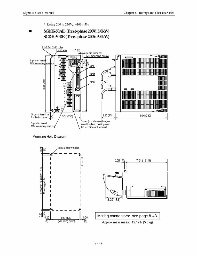
Sigma II User’s Manual Chapter 8: Ratings and Characteristics
8 - 48
* Rating 200 to 230Va c +10% -5%
SGDH-50AE (Three-phase 200V, 5.0kW) SGDH-50DE (Three-phase 200V, 5.0kW)
Approximate mass: 12.12lb (5.5kg)
SGDH-50AEVer.
YASKAWA SERVOPACK 200V
MODE/SET DATA/CHARGEPOWER
CN3
L1CL2CB1
V
U
CN1
CN2
B1B1
W
L 1
L 2
L 3
2
1
0.31 (8)
1.54
9.84 (
250)
5.31 (135)
4.92 (125) 0.20
4 x M5 screw holes
0.24
0.22
(Mounting pitch)
Heat sink2 Φ0.24 (Φ6) holes
Ground terminal2 × M4 screws
5-pin terminalM6 mount ing screw
3-pin terminalM5 mounting screws
6-pin terminalM5 mounting screws
2.95 (75) 9.06 (230)
Cover (not shown) hingesfrom this line, closing overthe lef t side of the front.
9.39 (
238.5
) ±0.0
20 (0
.5)Mo
untin
g pitc
h(6
)
(5)0.20(5)
(5.5)
Mounting Hole Diagram
(100°)
3.27 (83)
7.54 (191.5)0.28 (7)
CN3
CN1
CN2
(39)
Mating connectors: see page 8-43.
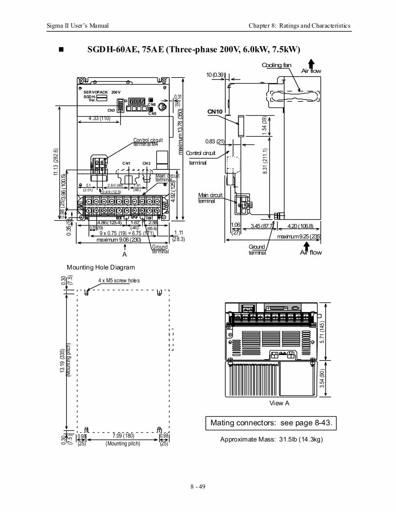
Sigma II User’s Manual Chapter 8: Ratings and Characteristics
8 - 49
SGDH-60AE, 75AE (Three-phase 200V, 6.0kW, 7.5kW)
L1 L2 L3 B1+ - B2 U V W
4 x M5 screw holes
Main circuit
0.75 (19)
51
4.86 (123.4) 1.67(65.6)2.58
(41)
2.60 (66)0.49 (12.5)(2.01)
1.81(46)
4.33 (110)
Control circuitterminal M4
CN2
CN3CN5
CN8
0.31(8)
CN1
maximum 9.06 (230)9 x 0.75 (19) = 6.75 (171) 1 .11
4.92 (
125)
maxim
um 13
.78 (3
50)
0.98 (
25)
terminal
A
Main circuitterminal
maximum 9.25 (235)
4.20 (106.8)3.45 (87.7)1.06(27)
10 (0.39)
CN10
Control circuitterminal
0.83 (21)
1.54
(39)
8.31 (
211.1
)
Groundterminal
Groundterminal
3.54 (
90)
5.71
(145
)
0.98(25)
7.09 (180)
13.19
(335
) 0.3
0(7.
5)0.3
0(7
.5)(M
ount
ing pi
tch)
Cooling fanAir flow
Air flow
Approximate Mass: 31.5lb (14.3kg)
View A
Mounting Hole Diagram
(Mounting pitch)
SERVOPACK 200VSGDH-
Ver.
11.13
(282
.6)3.9
6 (10
0.5)
0.35
(9)
0.98(25)
(28.3)
Mating connectors: see page 8-43.
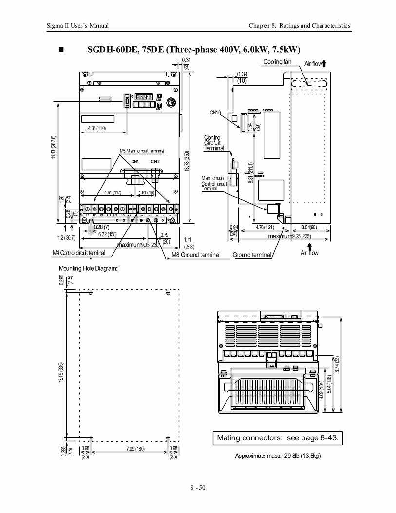
Sigma II User’s Manual Chapter 8: Ratings and Characteristics
8 - 50
SGDH-60DE, 75DE (Three-phase 400V, 6.0kW, 7.5kW)
8. 8. 8. 8 . 8 .
ControlCirc‘uitTerminal
Main circuit/
Terminal
Ground terminal
3.54(90)4.76 (121)0.94
8.74
(22)
13.78
(350
)
0.39
4.33 (110)
11.13
(282
.6)
CN8
CN 5
CN2CN1
4.61 (117) 1.81 (46)
0.28 (7)
0.28
1.2 (30.7) 1.110.79
maximum 9.05 (230)
6.22 (158)
M8 Ground terminal
M5 Main circuit terminal
maximum 9.25 (235)
Cooling fan Air flow
Air flow
CN10
L1 L2 L3 + − B1 B2 U V W
0.31
(24) (20)
(28.3)M4 Control circuit terminal
8.31 (
211.1
)
Control circuit
(10)
(8)(7)
1.26
(32)
7.09 (180)0.98
L1 L2 L3
Mounting Hole Diagram::
13.19
(335
)0.2
950.2
95(7.
5)(7.
5)
(25)0.98(25)
5.04 (
128)
4.09 (
104)
1.54
(39)
Approximate mass: 29.8lb (13.5kg)
Mating connectors: see page 8-43.

Sigma II User’s Manual Chapter 8: Ratings and Characteristics
8 - 51
SGDH-1AAE, 1EAE (Three-phase 200V, 11.0kW, 15.0kW)
17.13
(435
)
Cooling fan Air flow
1.54
9.69 (246)
L1 L2 L3 +1 B1 B2 U V W+2
0.295
(7.5)
4.92 (125)
maxim
um 17
.72 (4
50)
0.39 (10)12
.60 (3
20)
M4 Controlcircuit terminal
0.28 (7)
4.62 (117)0.94(24)11.22 (285)
Air flow
0.68 (17)
0.75
S E R V O P A C K 2 0 0 VS G D H —
V er.
Y A S K A W A
7.87 (200)
0.295
0.295
(7.5)
(19)
0.28 (7)
1.42 (
36)
0.35 (
9)
1.181.18
0.31
(30)(30)
0.28
M4 Mounting screws
(7) 0.295 (7.5)
17.13
(435
)
8. 8. 8. 8. 8.
5.51 (140)
CN2CN1
CN3
DATA
(8)
5.59 (
142) 8.2
3 (20
9)8.7
4 (2.2
2)10
.67 (2
71)
CN10
Main/Control circuit terminalM8 Ground terminal
(39)
10.55 (268)M8 Ground terminalM5 Main circuit terminal
0.28 2.91 (74) 5.28 (134)(7) 2.05 (52)
(7.5)
5.59 (
142)
Mounting Hole DiagramA
View A:
Approximate mass: 31.53lb (14.3kg)
Mating connectors: see page 8-43.
9.76 (
248)
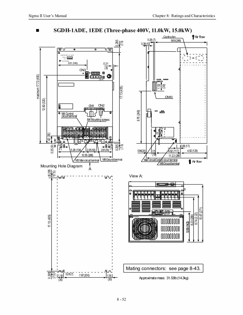
Sigma II User’s Manual Chapter 8: Ratings and Characteristics
8 - 52
SGDH-1ADE, 1EDE (Three-phase 400V, 11.0kW, 15.0kW)
17.13
(435
)
Cooling fan Air flow
1.53
9.69 (246)
L1 L2 L3 +1 B1 B2 U V W+2
0.295
(7.5)
4.92 (125)
maxim
um 17
.72 (4
50)
0.39 (10)12
.60 (3
20)
M4 Controlcircuit terminal
Approximate mass: 31.53lb (14.3kg)
0.28 (7)
4.62 (117)0.94(24)11.22 (285)
Air flow
0.68 (17)0.75
S E R V O P A C K 2 0 0 VS G D H —
V er.
Y A S K A W A
7.87 (200)
0.295
0.295
(7.5)
(19)
0.28 (7)
1.42 (
36)
0.35 (
9)
1.181.18
0.31
(30)(30)
0.28
M4 Mounting screws
(7) 0.295 (7.5)
17.13
(435
)
8. 8. 8. 8. 8.
5.51 (140)
CN2CN1
CN3
DATA
(8)
5.59 (
142) 8.2
3 (209
)8.7
4 (2.2
2)10
.67 (2
71)
CN10
Main circuit/Control circuit terminalM8 Ground terminal
(39)
10.55 (268)M8 Ground terminalM5 Main circuit terminal
0.28 2.91 (74) 5.28 (134)(7) 2.05 (52)
(7.5)
5.59 (
142)
Mounting Hole DiagramA
View A:
Mating connectors: see page 8-43.
9.76 (
248)
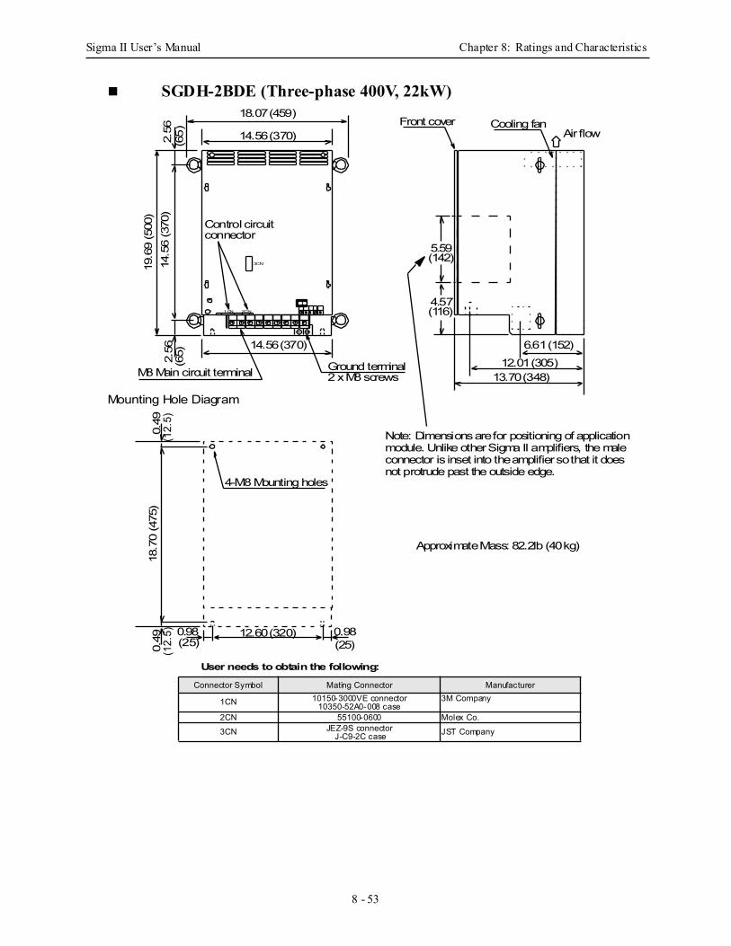
Sigma II User’s Manual Chapter 8: Ratings and Characteristics
8 - 53
SGDH-2BDE (Three-phase 400V, 22kW)
3CN
2CN1CN
14.56 (370)
14.5
6 (3
70)
18.07 (459)
14.56 (370)
0.49
0.49
(12.
5)(1
2.5)
12.60 (320)0.98(25)
0.98(25)
2.56
(65)
2.56
(65)
13.70 (348)12.01 (305)
6.61 (152)
18.7
0 (4
75)
4-M8 Mounting holes
Mounting Hole Diagram
M8 Main circuit terminal Ground terminal2 x M8 screws
Cooling fanFront coverAir flow
Control circuitconnector
19.6
9 (5
00)
4.57(116)
5.59(142)
Note: Dimensions are for positioning of application module. Unlike other Sigma II amplifiers, the maleconnector is inset into the amplifier so that it does not protrude past the outside edge.
Connector Symbol Mating Connector Manufacturer
1CN 10150-3000VE connector10350-52A0-008 case
3M Company
2CN 55100-0600 Molex Co.
3CN JEZ-9S connectorJ-C9-2C case JST Company
User needs to obtain the following:
Approximate Mass: 82.2lb (40 kg)
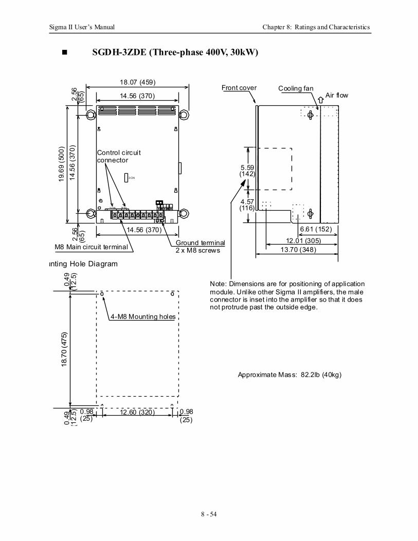
Sigma II User’s Manual Chapter 8: Ratings and Characteristics
8 - 54
SGDH-3ZDE (Three-phase 400V, 30kW)
3 CN
2CN1 CN
14.56 (370)
14.5
6 (3
70)
18.07 (459)
14.56 (370)
0.49
0.49
(12.
5)(1
2.5)
12.60 (320)0.98(25)
0.98(25)
2.56
(65)
2.56
(65)
13.70 (348)12.01 (305)
6.61 (152)
18.7
0 (4
75)
4-M8 Mounting holes
unting Hole Diagram
M8 Main circuit terminal Ground terminal2 x M8 screws
Cooling fanFront coverAir flow
Control c ircuitconnector
19.6
9 (5
00)
4.57(116)
5.59(142)
Approximate Mass: 82.2lb (40kg)
Note: Dimensions are for positioning of applicationmodule. Unlike other Sigma II amplifiers, the maleconnector is inset into the amplifier so that it does not protrude past the outside edge.
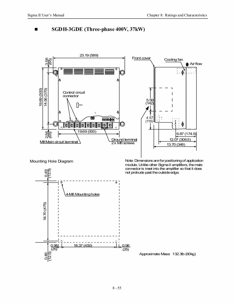
Sigma II User’s Manual Chapter 8: Ratings and Characteristics
8 - 55
SGDH-3GDE (Three-phase 400V, 37kW)
19.69 (500)
14.5
6 (3
70)
23.19 (589)
0.49
0.49
(12.
5)(1
2.5)
18.37 (450)0.98(25)
0.98(25)
2.56
(65)
13.70 (348)12.07 (306.5)
6.87 (174.5)
18.7
0 (4
75)
4-M8 Mounting holes
Mounting Hole Diagram
M8 Main circuit terminal Ground terminal2 x M8 screws
Cooling fanFront coverAir flow
3CN
2CN1CN
3.56
(65)
Approximate Mass: 132.3lb (60kg)
Control circuitconnector
Mating connectors: see page 17.
19.6
9 (5
00)
5.59(142)
4.57(116)
Note: Dimensions are for positioning of applicationmodule. Unlike other Sigma II amplifiers, the maleconnector is inset into the amplifier so that it doesnot protrude past the outside edge.
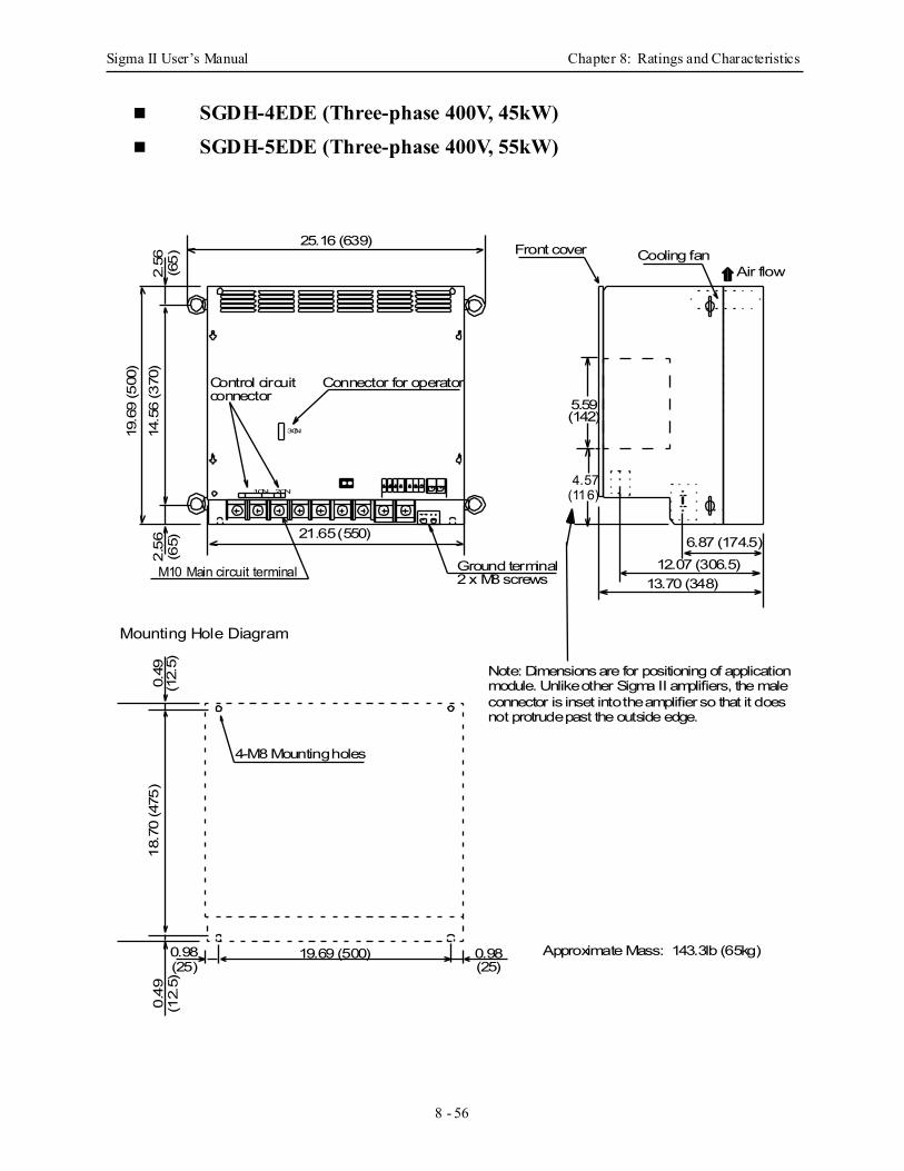
Sigma II User’s Manual Chapter 8: Ratings and Characteristics
8 - 56
SGDH-4EDE (Three-phase 400V, 45kW)
SGDH-5EDE (Three-phase 400V, 55kW)
3CN
2CN1CN
21.65 (550)
14.5
6 (3
70)
25.16 (639)
0.49
0.49
(12.
5)(1
2.5)
19.69 (500)0.98(25)
0.98(25)
2.56
(65)
13.70 (348)12.07 (306.5)
6.87 (174.5)
18.7
0 (4
75)
4-M8 Mounting holes
Mounting Hole Diagram
M10 Main circuit terminal Ground terminal2 x M8 screws
Cooling fanFront coverAir flow2.
56(6
5)
Approximate Mass: 143.3lb (65kg)
Control circuit Connector for operatorconnector
Mating connectors: see page 17.
19.6
9 (5
00)
5.59(142)
4.57(116)
Note: Dimensions are for positioning of applicationmodule. Unlike other Sigma II amplifiers, the maleconnector is inset into the amplifier so that it doesnot protrude past the outside edge.
Sigma II User’s Manual Chapter 9: Inspection, Maintenance, and Troubleshooting
9 - 1
9 Inspection, Maintenance, and TroubleshootingThis chapter describes the basic inspection and maintenance to be carried out by the user. In addition, troubleshooting proce-dures are described for problems which generate an alarm dis-play and for problems which result in no alarm display.
9.1 Servodrive Inspection and Maintenance .............................................................. 9-2
9.1.1 Servomotor Inspection ................................................................................ 9-2
9.1.2 Servo Amplifier Inspection......................................................................... 9-3
9.1.3 Replacing the Battery for the Absolute Encoder ........................................ 9-4
9.2 Troubleshooting ................................................................................................... 9-5
9.2.1 Troubleshooting Problems with Alarm Displays ........................................ 9-5
9.2.2 Troubleshooting Problems with No Alarm Display ................................. 9-39
9.2.3 Alarm Display Table ................................................................................. 9-41
9.2.4 Warning Displays ...................................................................................... 9-43
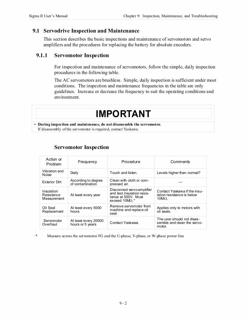
Sigma II User’s Manual Chapter 9: Inspection, Maintenance, and Troubleshooting
9 - 2
9.1 Servodrive Inspection and MaintenanceThis section describes the basic inspections and maintenance of servomotors and servo amplifiers and the procedures for replacing the battery for absolute encoders.
9.1.1 Servomotor Inspection
For inspection and maintenance of servomotors, follow the simple, daily inspection procedures in the following table.The AC servomotors are brushless. Simple, daily inspection is sufficient under most conditions. The inspection and maintenance frequencies in the table are only guidelines. Increase or decrease the frequency to suit the operating conditions and environment.
Servomotor Inspection
* Measure across the servomotor FG and the U-phase, V-phase, or W-phase power line
• During inspection and maintenance, do not disassemble the servomotor.If disassembly of the servomotor is required, contact Yaskawa.
Action or Problem Frequency Procedure Comments
Vibration and Noise Daily Touch and listen. Levels higher than normal?
Exterior Dirt According to degree of contamination
Clean with cloth or com-pressed air. —
Insulation ResistanceMeasurement
At least every yearDisconnect servo amplifier and test insulation resis-tance at 500V. Must exceed 10MΩ.*
Contact Yaskawa if the insu-lation resistance is below 10MΩ.
Oil Seal Replacement
At least every 5000 hours
Remove servomotor from machine and replace oil seal.
Applies only to motors with oil seals.
Servomotor Overhaul
At least every 20000 hours or 5 years Contact Yaskawa.
The user should not disas-semble and clean the servo-motor.
IMPORTANT
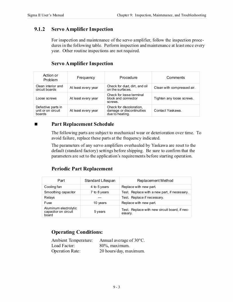
Sigma II User’s Manual Chapter 9: Inspection, Maintenance, and Troubleshooting
9 - 3
9.1.2 Servo Amplifier Inspection
For inspection and maintenance of the servo amplifier, follow the inspection proce-dures in the following table. Perform inspection and maintenance at least once every year. Other routine inspections are not required.
Servo Amplifier Inspection
Part Replacement Schedule The following parts are subject to mechanical wear or deterioration over time. To avoid failure, replace these parts at the frequency indicated. The parameters of any servo amplifiers overhauled by Yaskawa are reset to the default (standard factory) settings before shipping. Be sure to confirm that the parameters are set to the application’s requirements before starting operation.
Periodic Part Replacement
Operating Conditions: Ambient Temperature: Annual average of 30°C.Load Factor: 80%, maximum.Operation Rate: 20 hours/day, maximum.
Action or Problem Frequency Procedure Comments
Clean interior and circuit boards At least every year Check for dust, dirt, and oil
on the surfaces. Clean with compressed air.
Loose screws At least every yearCheck for loose terminal block and connector screws.
Tighten any loose screws.
Defective parts in unit or on circuit boards
At least every yearCheck for discoloration, damage or discontinuities due to heating.
Contact Yaskawa.
Part Standard Lifespan Replacement MethodCooling fan 4 to 5 years Replace with new part.Smoothing capacitor 7 to 8 years Test. Replace with a new part, if necessary.Relays — Test. Replace if necessary.Fuse 10 years Replace with new part. Aluminum electrolytic capacitor on circuit board
5 years Test. Replace with new circuit board, if nec-essary.
Sigma II User’s Manual Chapter 9: Inspection, Maintenance, and Troubleshooting
9 - 4
9.1.3 Replacing the Battery for the Absolute Encoder
If the voltage of the battery for an absolute encoder drops to about 2.7V or less, an Absolute Encoder Battery Alarm (A. 83*) will occur in the servo amplifier. This alarm occurs when the servo amplifier receives a signal from the absolute encoder when the power to the servo amplifier is turned ON. Therefore, the servo amplifier will not give an alarm when the battery voltage drops below the minimum voltage level while the power is being supplied to the servo amplifier.Refer to 5.7.3 Handling Batteries for the battery type recommended for absolute encoders.Replace the battery using the following procedure if the battery voltage drops below the minimum required battery voltage.
Battery Replacement Procedure1. Replace the battery while the control power to the servo amplifier is ON.2. After replacement, turn OFF the power to the servo amplifier in order to clear the
Absolute Encoder Battery Alarm (A. 83).3. Turn ON the power to the servo amplifier again and confirm that it operates
properly.
Note: The absolute encoder data will be lost when the control power to the servo amplifier is turned OFF and the encoder cable is disconnected from the battery. If the data is lost, refer to 5.7.4 I. Absolute Encoder Setup and follow the procedure to initialize the absolute encoder.
*Alarm A.83 is described in greater detail on page 9 - 22.
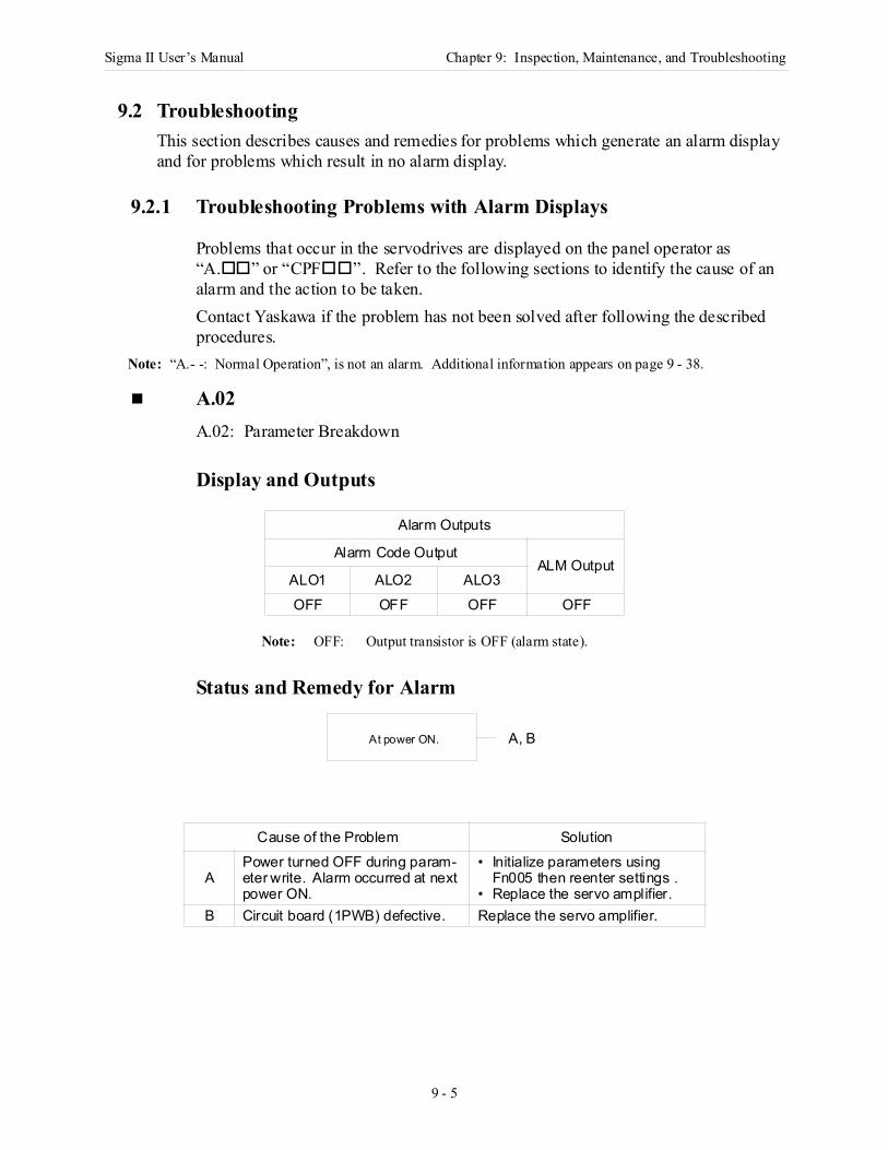
Sigma II User’s Manual Chapter 9: Inspection, Maintenance, and Troubleshooting
9 - 5
9.2 TroubleshootingThis section describes causes and remedies for problems which generate an alarm display and for problems which result in no alarm display.
9.2.1 Troubleshooting Problems with Alarm Displays
Problems that occur in the servodrives are displayed on the panel operator as “A. ” or “CPF ”. Refer to the following sections to identify the cause of an alarm and the action to be taken.Contact Yaskawa if the problem has not been solved after following the described procedures.
Note: “A.- -: Normal Operation”, is not an alarm. Additional information appears on page 9 - 38.
A.02A.02: Parameter Breakdown
Display and Outputs
Note: OFF: Output transistor is OFF (alarm state).
Status and Remedy for Alarm
Alarm Outputs
Alarm Code OutputALM Output
ALO1 ALO2 ALO3OFF OFF OFF OFF
Cause of the Problem Solution
APower turned OFF during param-eter write. Alarm occurred at next power ON.
• Initialize parameters using Fn005 then reenter settings .
• Replace the servo amplifier.B Circuit board (1PWB) defective. Replace the servo amplifier.
At power ON. A, B
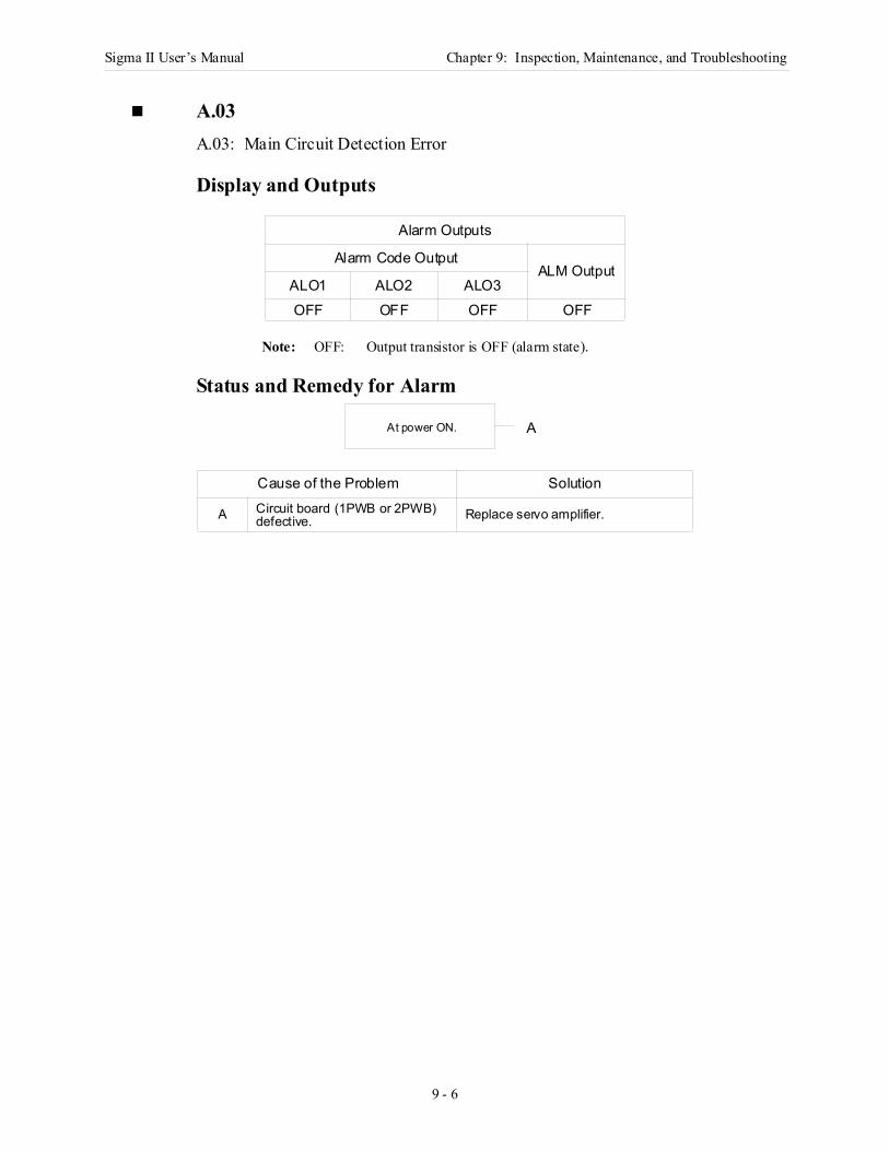
Sigma II User’s Manual Chapter 9: Inspection, Maintenance, and Troubleshooting
9 - 6
A.03A.03: Main Circuit Detection Error
Display and Outputs
Note: OFF: Output transistor is OFF (alarm state).
Status and Remedy for Alarm
Alarm Outputs
Alarm Code OutputALM Output
ALO1 ALO2 ALO3OFF OFF OFF OFF
Cause of the Problem Solution
A Circuit board (1PWB or 2PWB) defective. Replace servo amplifier.
At power ON. A
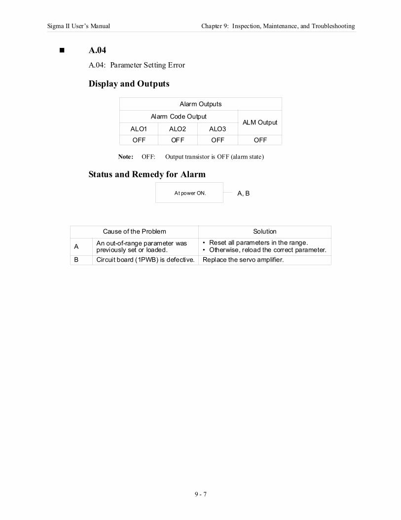
Sigma II User’s Manual Chapter 9: Inspection, Maintenance, and Troubleshooting
9 - 7
A.04A.04: Parameter Setting Error
Display and Outputs
Note: OFF: Output transistor is OFF (alarm state)
Status and Remedy for Alarm
Alarm Outputs
Alarm Code OutputALM Output
ALO1 ALO2 ALO3OFF OFF OFF OFF
Cause of the Problem Solution
A An out-of-range parameter was previously set or loaded.
• Reset all parameters in the range.• Otherwise, reload the correct parameter.
B Circuit board (1PWB) is defective. Replace the servo amplifier.
At power ON. A, B
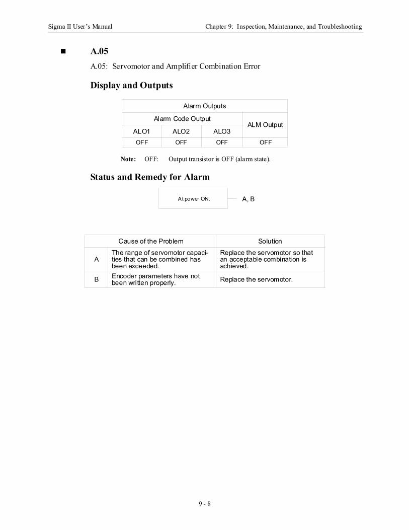
Sigma II User’s Manual Chapter 9: Inspection, Maintenance, and Troubleshooting
9 - 8
A.05A.05: Servomotor and Amplifier Combination Error
Display and Outputs
Note: OFF: Output transistor is OFF (alarm state).
Status and Remedy for Alarm
Alarm Outputs
Alarm Code OutputALM Output
ALO1 ALO2 ALO3OFF OFF OFF OFF
Cause of the Problem Solution
AThe range of servomotor capaci-ties that can be combined has been exceeded.
Replace the servomotor so that an acceptable combination is achieved.
B Encoder parameters have not been written properly. Replace the servomotor.
At power ON. A, B
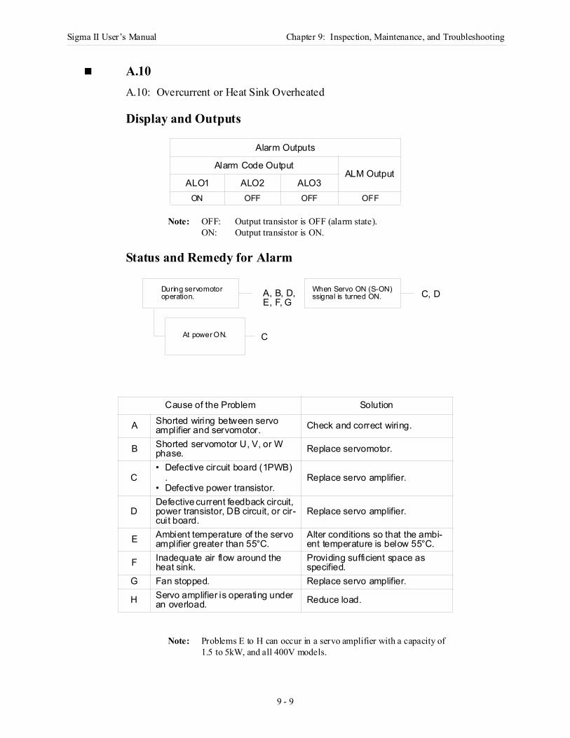
Sigma II User’s Manual Chapter 9: Inspection, Maintenance, and Troubleshooting
9 - 9
A.10A.10: Overcurrent or Heat Sink Overheated
Display and Outputs
Note: OFF: Output transistor is OFF (alarm state).ON: Output transistor is ON.
Status and Remedy for Alarm
Note: Problems E to H can occur in a servo amplifier with a capacity of 1.5 to 5kW, and all 400V models.
Alarm Outputs
Alarm Code OutputALM Output
ALO1 ALO2 ALO3ON OFF OFF OFF
Cause of the Problem Solution
A Shorted wiring between servo amplifier and servomotor. Check and correct wiring.
B Shorted servomotor U, V, or W phase. Replace servomotor.
C• Defective circuit board (1PWB)
.• Defective power transistor.
Replace servo amplifier.
DDefective current feedback circuit, power transistor, DB circuit, or cir-cuit board.
Replace servo amplifier.
E Ambient temperature of the servo amplifier greater than 55°C.
Alter conditions so that the ambi-ent temperature is below 55°C.
F Inadequate air flow around the heat sink.
Providing sufficient space as specified.
G Fan stopped. Replace servo amplifier.
H Servo amplifier is operating under an overload. Reduce load.
When Servo ON (S-ON)
At power ON.
During servomotoroperation. ssignal is turned ON.A, B, D,
C
C, DE, F, G
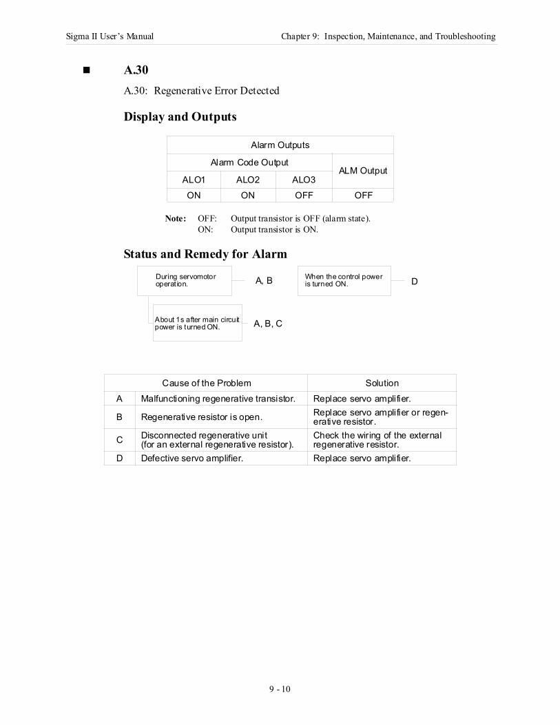
Sigma II User’s Manual Chapter 9: Inspection, Maintenance, and Troubleshooting
9 - 10
A.30A.30: Regenerative Error Detected
Display and Outputs
Note: OFF: Output transistor is OFF (alarm state).ON: Output transistor is ON.
Status and Remedy for Alarm
Alarm Outputs
Alarm Code OutputALM Output
ALO1 ALO2 ALO3ON ON OFF OFF
Cause of the Problem SolutionA Malfunctioning regenerative transistor. Replace servo amplifier.
B Regenerative resistor is open. Replace servo amplifier or regen-erative resistor.
C Disconnected regenerative unit (for an external regenerative resistor).
Check the wiring of the external regenerative resistor.
D Defective servo amplifier. Replace servo amplifier.
When the control power
About 1s after main circuit
During servomotoroperat ion. is turned ON.A, B
A, B, C
D
power is turned ON.
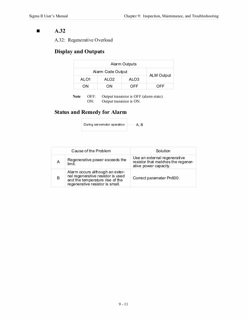
Sigma II User’s Manual Chapter 9: Inspection, Maintenance, and Troubleshooting
9 - 11
A.32A.32: Regenerative Overload
Display and Outputs
Note OFF: Output transistor is OFF (alarm state).ON: Output transistor is ON.
Status and Remedy for Alarm
Alarm Outputs
Alarm Code OutputALM Output
ALO1 ALO2 ALO3ON ON OFF OFF
Cause of the Problem Solution
A Regenerative power exceeds the limit.
Use an external regenerative resistor that matches the regener-ative power capacity.
BAlarm occurs although an exter-nal regenerative resistor is used and the temperature rise of the regenerative resistor is small.
Correct parameter Pn600.
During servomotor operation. A, B
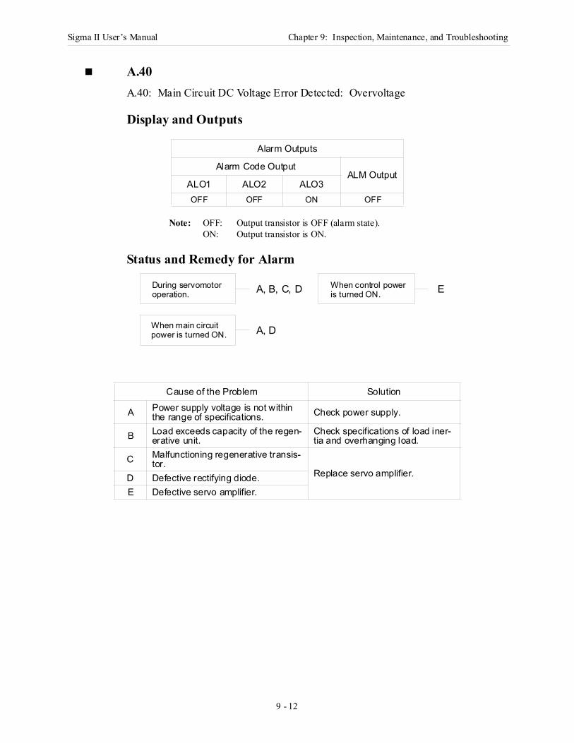
Sigma II User’s Manual Chapter 9: Inspection, Maintenance, and Troubleshooting
9 - 12
A.40A.40: Main Circuit DC Voltage Error Detected: Overvoltage
Display and Outputs
Note: OFF: Output transistor is OFF (alarm state).ON: Output transistor is ON.
Status and Remedy for Alarm
Alarm Outputs
Alarm Code OutputALM Output
ALO1 ALO2 ALO3OFF OFF ON OFF
Cause of the Problem Solution
A Power supply voltage is not within the range of specifications. Check power supply.
B Load exceeds capacity of the regen-erative unit.
Check specifications of load iner-tia and overhanging load.
C Malfunctioning regenerative transis-tor.
Replace servo amplifier.D Defective rectifying diode.E Defective servo amplifier.
A, B, C, D E
A, D
During servomotoroperation.
When main circuitpower is turned ON.
When control poweris turned ON.
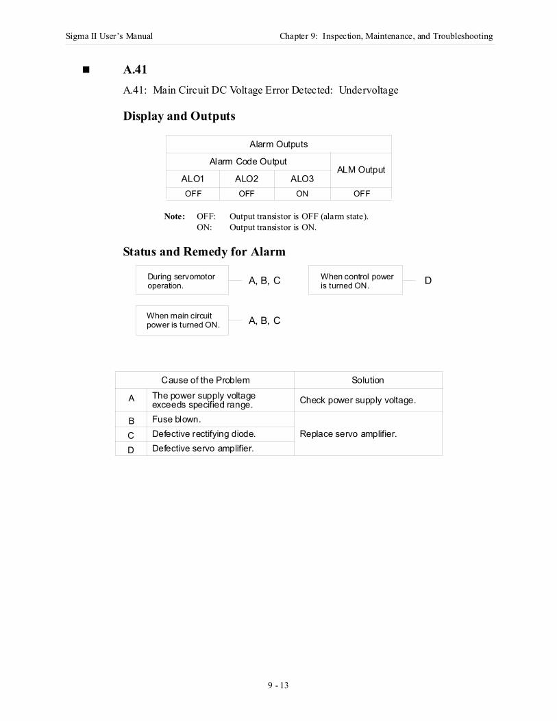
Sigma II User’s Manual Chapter 9: Inspection, Maintenance, and Troubleshooting
9 - 13
A.41A.41: Main Circuit DC Voltage Error Detected: Undervoltage
Display and Outputs
Note: OFF: Output transistor is OFF (alarm state).ON: Output transistor is ON.
Status and Remedy for Alarm
Alarm Outputs
Alarm Code OutputALM Output
ALO1 ALO2 ALO3OFF OFF ON OFF
Cause of the Problem Solution
A The power supply voltage exceeds specified range. Check power supply voltage.
B Fuse blown.Replace servo amplifier.C Defective rectifying diode.
D Defective servo amplifier.
A, B, C D
A, B, C
During servomotoroperation.
When main circuitpower is turned ON.
When control poweris turned ON.
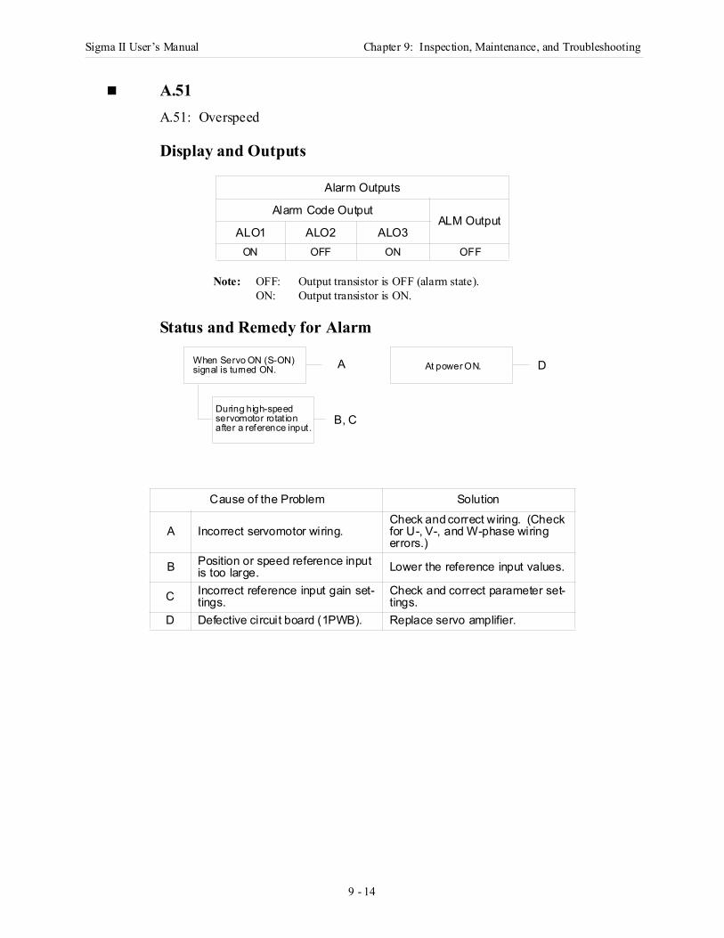
Sigma II User’s Manual Chapter 9: Inspection, Maintenance, and Troubleshooting
9 - 14
A.51A.51: Overspeed
Display and Outputs
Note: OFF: Output transistor is OFF (alarm state).ON: Output transistor is ON.
Status and Remedy for Alarm
Alarm Outputs
Alarm Code OutputALM Output
ALO1 ALO2 ALO3ON OFF ON OFF
Cause of the Problem Solution
A Incorrect servomotor wiring.Check and correct wiring. (Check for U-, V-, and W-phase wiring errors.)
B Position or speed reference input is too large. Lower the reference input values.
C Incorrect reference input gain set-tings.
Check and correct parameter set-tings.
D Defective circuit board (1PWB). Replace servo amplifier.
During high-speed
At power ON.When Servo ON (S-ON)signal is turned ON.
servomotor rotat ionafter a reference input.
A
B, C
D

Sigma II User’s Manual Chapter 9: Inspection, Maintenance, and Troubleshooting
9 - 15
A.71, A.72A.71: Overload: High LoadA.72: Overload: Low Load.
The alarm output, status, and remedy for A.71 are the same as for A.72.
Display and Outputs
Note: OFF: Output transistor is OFF (alarm state).ON: Output transistor is ON.
Status and Remedy for Alarm
Alarm Outputs
Alarm Code OutputALM Output
ALO1 ALO2 ALO3ON ON ON OFF
Cause of the Problem Solution
A Incorrect or disconnected servo-motor wiring.
Check wiring and connectors at the servomotor.
B Load greatly exceeds rated torque.
Reduce load torque and inertia. Otherwise, replace with a larger capacity servomotor.
C Defective circuit board (1PWB). Replace servo amplifier.
When Servo ON (S-ON)signal is turned ON.
When speed referenceis entered.
At power ON. C
B
B
A
No servomotor rotation.
During servomotoroperation.
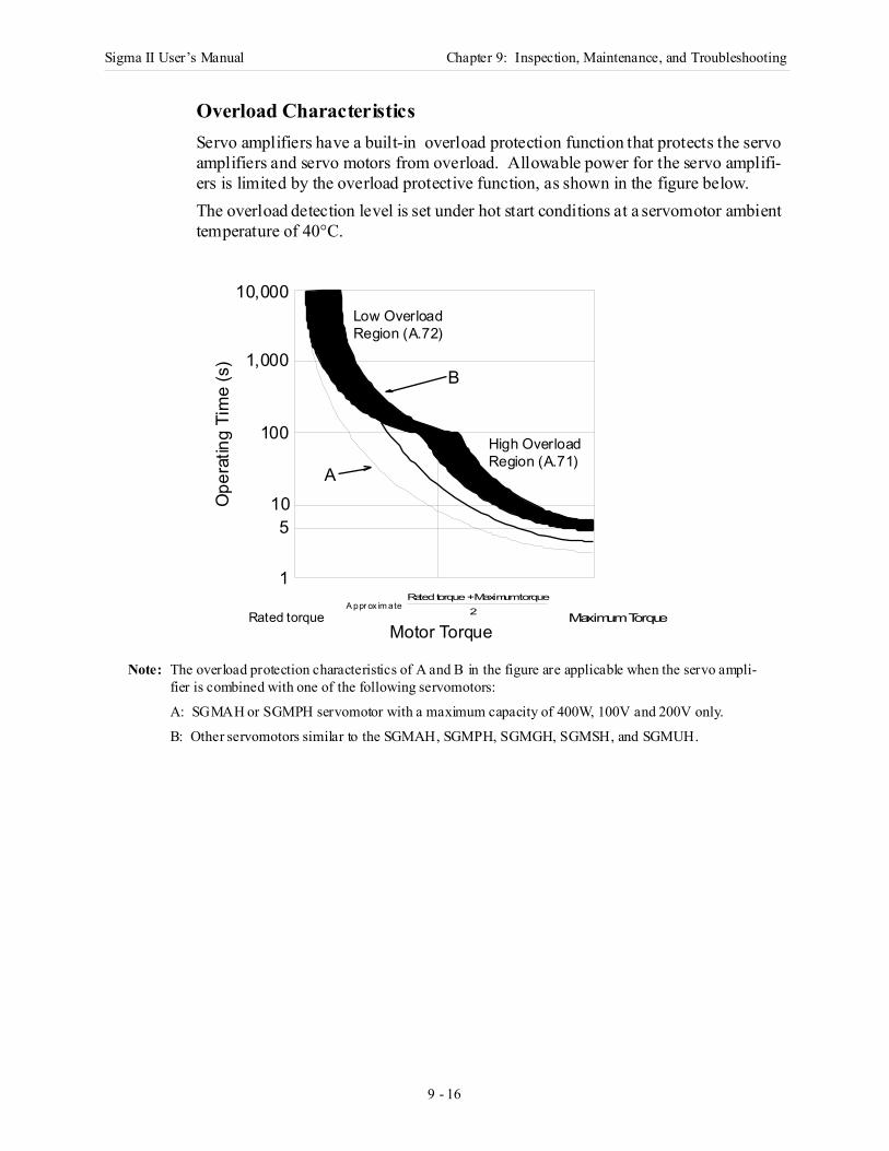
Sigma II User’s Manual Chapter 9: Inspection, Maintenance, and Troubleshooting
9 - 16
Overload Characteristics Servo amplifiers have a built-in overload protection function that protects the servo amplifiers and servo motors from overload. Allowable power for the servo amplifi-ers is limited by the overload protective function, as shown in the figure below.The overload detection level is set under hot start conditions at a servomotor ambient temperature of 40°C.
Note: The overload protection characteristics of A and B in the figure are applicable when the servo ampli-fier is combined with one of the following servomotors:
A: SGMAH or SGMPH servomotor with a maximum capacity of 400W, 100V and 200V only.
B: Other servomotors similar to the SGMAH, SGMPH, SGMGH, SGMSH, and SGMUH.
Rated torqueA ppr ox im ate
Rated torque + Maximum torque2 Maximum Torque
B
A
10,000
1,000
100
105
1
Ope
ratin
g Ti
me
(s)
Motor Torque
Low Overload Region (A.72)
High OverloadRegion (A.71)
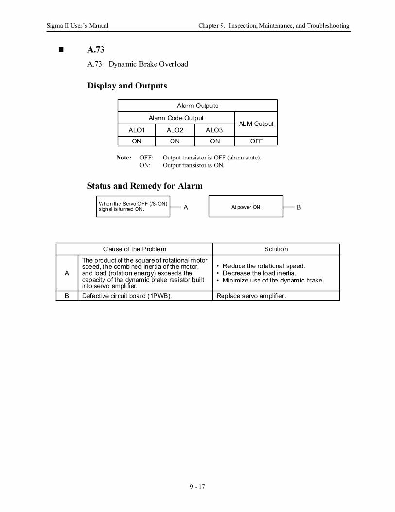
Sigma II User’s Manual Chapter 9: Inspection, Maintenance, and Troubleshooting
9 - 17
A.73A.73: Dynamic Brake Overload
Display and Outputs
Note: OFF: Output transistor is OFF (alarm state).ON: Output transistor is ON.
Status and Remedy for Alarm
Alarm Outputs
Alarm Code OutputALM Output
ALO1 ALO2 ALO3ON ON ON OFF
Cause of the Problem Solution
A
The product of the square of rotational motor speed, the combined inertia of the motor, and load (rotation energy) exceeds the capacity of the dynamic brake resistor built into servo amplifier.
• Reduce the rotational speed.• Decrease the load inertia.• Minimize use of the dynamic brake.
B Defective circuit board (1PWB). Replace servo amplifier.
When the Servo OFF (/S-ON)signal is turned ON. At power ON.A B
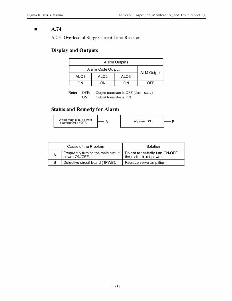
Sigma II User’s Manual Chapter 9: Inspection, Maintenance, and Troubleshooting
9 - 18
A.74A.74: Overload of Surge Current Limit Resistor
Display and Outputs
Note: OFF: Output transistor is OFF (alarm state).ON: Output transistor is ON.
Status and Remedy for Alarm
Alarm Outputs
Alarm Code OutputALM Output
ALO1 ALO2 ALO3ON ON ON OFF
Cause of the Problem Solution
A Frequently turning the main circuit power ON/OFF.
Do not repeatedly turn ON/OFF the main circuit power.
B Defective circuit board (1PWB). Replace servo amplifier.
When main circuit poweris turned ON or OFF. At power ON.A B
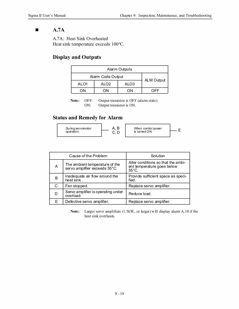
Sigma II User’s Manual Chapter 9: Inspection, Maintenance, and Troubleshooting
9 - 19
A.7AA.7A: Heat Sink OverheatedHeat sink temperature exceeds 100°C.
Display and Outputs
Note: OFF: Output transistor is OFF (alarm state).ON: Output transistor is ON.
Status and Remedy for Alarm
Note: Larger servo amplifiers (1.5kW., or larger) will display alarm A.10 if the heat sink overheats.
Alarm Outputs
Alarm Code OutputALM Output
ALO1 ALO2 ALO3ON ON ON OFF
Cause of the Problem Solution
A The ambient temperature of the servo amplifier exceeds 55°C.
Alter conditions so that the ambi-ent temperature goes below 55°C.
B Inadequate air flow around the heat sink .
Provide sufficient space as speci-fied.
C Fan stopped. Replace servo amplifier.
D Servo amplifier is operating under overload. Reduce load.
E Defective servo amplifier. Replace servo amplifier.
During servomotoroperation.
When control poweris turned ON. EA, B
C, D
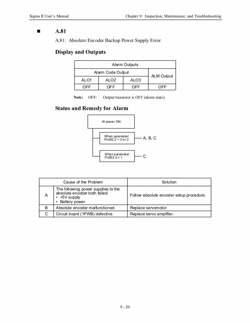
Sigma II User’s Manual Chapter 9: Inspection, Maintenance, and Troubleshooting
9 - 20
A.81A.81: Absolute Encoder Backup Power Supply Error
Display and Outputs
Note: OFF: Output transistor is OFF (alarm state).
Status and Remedy for Alarm
Alarm Outputs
Alarm Code OutputALM Output
ALO1 ALO2 ALO3OFF OFF OFF OFF
Cause of the Problem Solution
AThe following power supplies to the absolute encoder both failed:• +5V supply• Battery power
Follow absolute encoder setup procedure.
B Absolute encoder malfunctioned. Replace servomotor.C Circuit board (1PWB) defective. Replace servo amplifier.
A, B, C
At power ON.
When parameterPn002.2 = 0 or 2
When parameterPn002.2 = 1 C
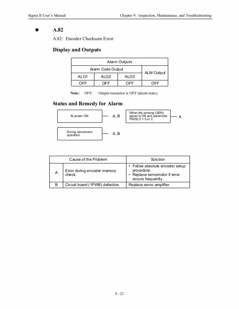
Sigma II User’s Manual Chapter 9: Inspection, Maintenance, and Troubleshooting
9 - 21
A.82 A.82: Encoder Checksum Error
Display and Outputs
Note: OFF: Output transistor is OFF (alarm state).
Status and Remedy for Alarm
Alarm Outputs
Alarm Code OutputALM Output
ALO1 ALO2 ALO3OFF OFF OFF OFF
Cause of the Problem Solution
A Error during encoder memory check.
• Follow absolute encoder setup procedure.
• Replace servomotor if error occurs frequently.
B Circuit board (1PWB) defective. Replace servo amplifier.
At power ON.
During servomotor
When the sensing (SEN)signal is ON and parameterPn002.2 = 0 or 2.
operat ion.
AA, B
A, B
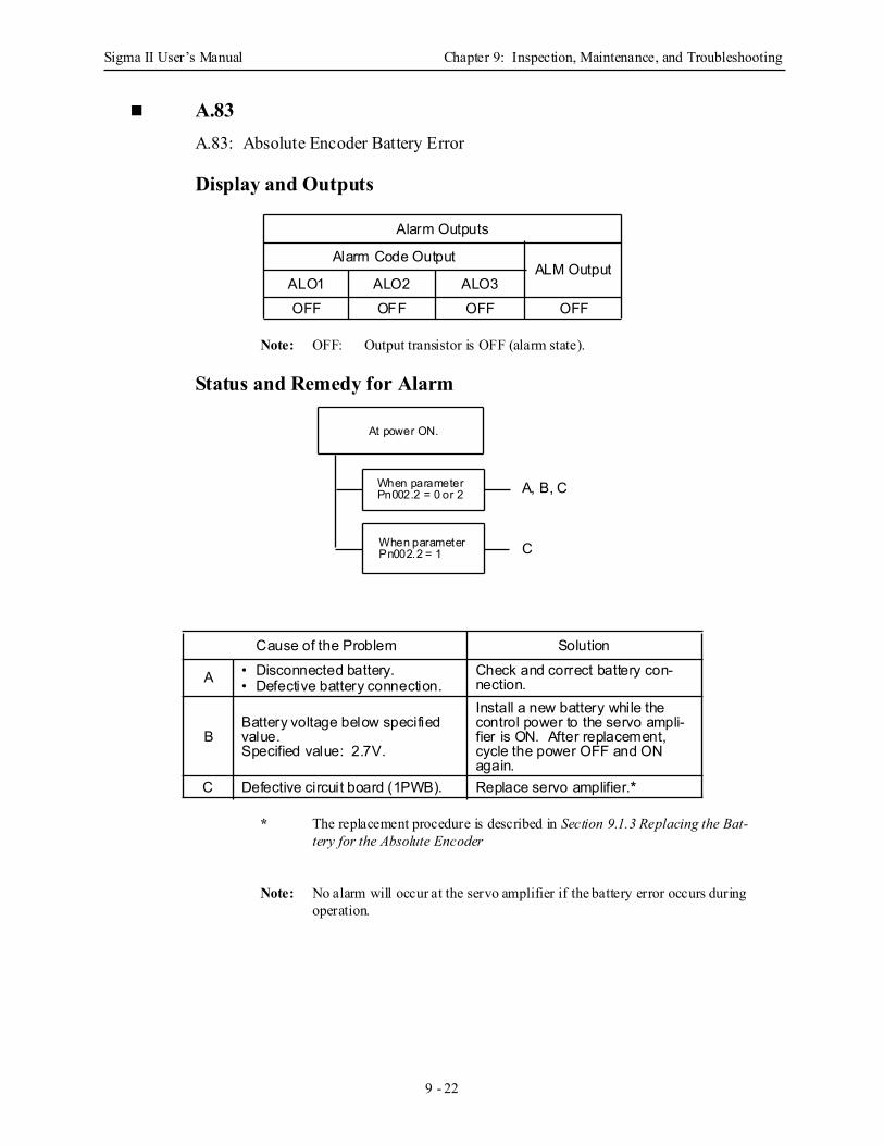
Sigma II User’s Manual Chapter 9: Inspection, Maintenance, and Troubleshooting
9 - 22
A.83A.83: Absolute Encoder Battery Error
Display and Outputs
Note: OFF: Output transistor is OFF (alarm state).
Status and Remedy for Alarm
* The replacement procedure is described in Section 9.1.3 Replacing the Bat-tery for the Absolute Encoder
Note: No alarm will occur at the servo amplifier if the battery error occurs during operation.
Alarm Outputs
Alarm Code OutputALM Output
ALO1 ALO2 ALO3OFF OFF OFF OFF
Cause of the Problem Solution
A • Disconnected battery.• Defective battery connection.
Check and correct battery con-nection.
BBattery voltage below specified value.Specified value: 2.7V.
Install a new battery while the control power to the servo ampli-fier is ON. After replacement, cycle the power OFF and ON again.
C Defective circuit board (1PWB). Replace servo amplifier.*
A, B, C
At power ON.
When parameterPn002.2 = 0 or 2
When parameterPn002.2 = 1 C
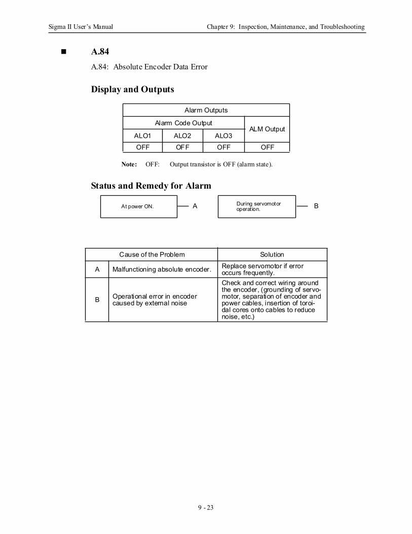
Sigma II User’s Manual Chapter 9: Inspection, Maintenance, and Troubleshooting
9 - 23
A.84A.84: Absolute Encoder Data Error
Display and Outputs
Note: OFF: Output transistor is OFF (alarm state).
Status and Remedy for Alarm
Alarm Outputs
Alarm Code OutputALM Output
ALO1 ALO2 ALO3OFF OFF OFF OFF
Cause of the Problem Solution
A Malfunctioning absolute encoder. Replace servomotor if error occurs frequently.
B Operational error in encoder caused by external noise
Check and correct wiring around the encoder, (grounding of servo-motor, separation of encoder and power cables, insertion of toroi-dal cores onto cables to reduce noise, etc.)
At power ON. During servomotoroperat ion.A B

Sigma II User’s Manual Chapter 9: Inspection, Maintenance, and Troubleshooting
9 - 24
A.85A.85: Absolute Encoder Overspeed
Display and Outputs
Not: OFF: Output transistor is OFF (alarm state).
Status and Remedy for Alarm
Alarm Outputs
Alarm Code OutputALM Output
ALO1 ALO2 ALO3OFF OFF OFF OFF
Cause of the Problem Solution
A Absolute encoder turned ON at motor speed exceeding 200rpm.
Turn ON power supply with the servomotor stopped.
B Circuit board (1PWB) defective. Replace servo amplifier.
At power ON. A, B
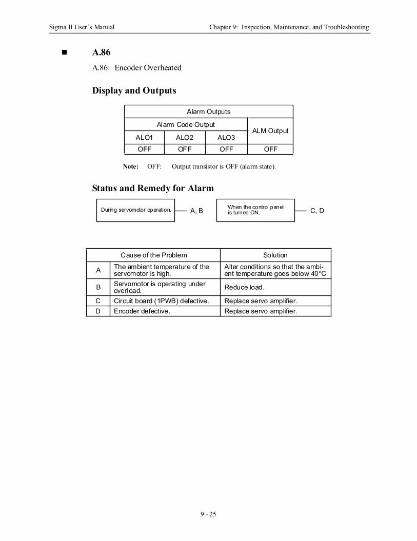
Sigma II User’s Manual Chapter 9: Inspection, Maintenance, and Troubleshooting
9 - 25
A.86A.86: Encoder Overheated
Display and Outputs
Note: OFF: Output transistor is OFF (alarm state).
Status and Remedy for Alarm
Alarm Outputs
Alarm Code OutputALM Output
ALO1 ALO2 ALO3OFF OFF OFF OFF
Cause of the Problem Solution
A The ambient temperature of the servomotor is high.
Alter conditions so that the ambi-ent temperature goes below 40°C
B Servomotor is operating under overload. Reduce load.
C Circuit board (1PWB) defective. Replace servo amplifier.D Encoder defective. Replace servo amplifier.
During servomotor operation. When the control panelis turned ON.A, B C, D
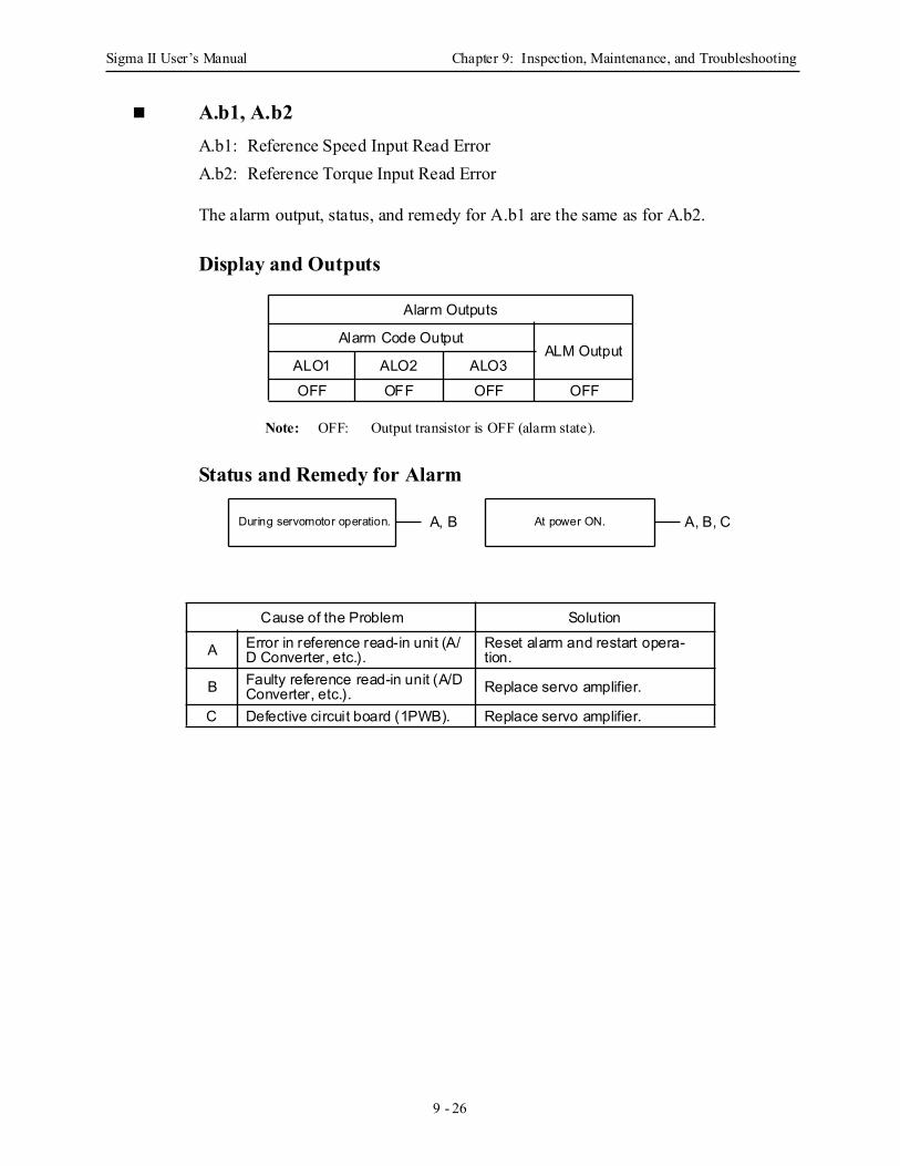
Sigma II User’s Manual Chapter 9: Inspection, Maintenance, and Troubleshooting
9 - 26
A.b1, A.b2A.b1: Reference Speed Input Read ErrorA.b2: Reference Torque Input Read Error
The alarm output, status, and remedy for A.b1 are the same as for A.b2.
Display and Outputs
Note: OFF: Output transistor is OFF (alarm state).
Status and Remedy for Alarm
Alarm Outputs
Alarm Code OutputALM Output
ALO1 ALO2 ALO3OFF OFF OFF OFF
Cause of the Problem Solution
A Error in reference read-in unit (A/D Converter, etc.).
Reset alarm and restart opera-tion.
B Faulty reference read-in unit (A/D Converter, etc.). Replace servo amplifier.
C Defective circuit board (1PWB). Replace servo amplifier.
During servomotor operation. At power ON.A, B A, B, C
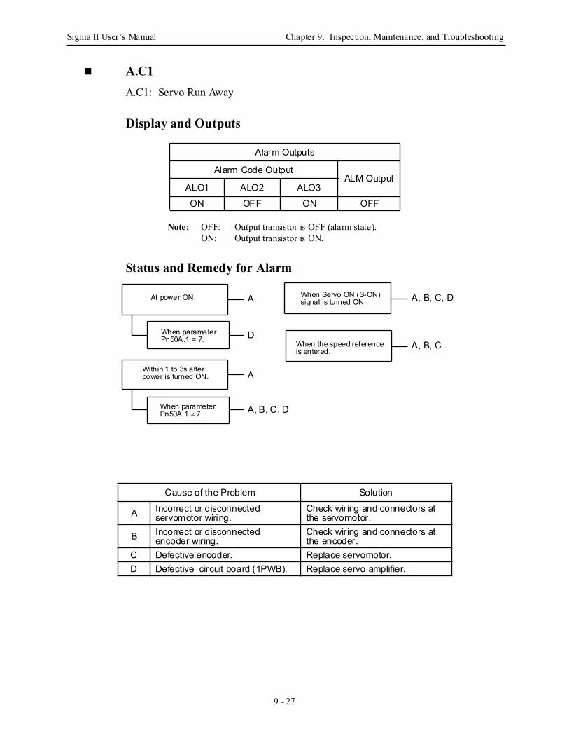
Sigma II User’s Manual Chapter 9: Inspection, Maintenance, and Troubleshooting
9 - 27
A.C1A.C1: Servo Run Away
Display and Outputs
Note: OFF: Output transistor is OFF (alarm state).ON: Output transistor is ON.
Status and Remedy for Alarm
Alarm Outputs
Alarm Code OutputALM Output
ALO1 ALO2 ALO3ON OFF ON OFF
Cause of the Problem Solution
A Incorrect or disconnected servomotor wiring.
Check wiring and connectors at the servomotor.
B Incorrect or disconnected encoder wiring.
Check wiring and connectors at the encoder.
C Defective encoder. Replace servomotor.D Defective circuit board (1PWB). Replace servo amplifier.
A A, B, C, D
A, B, C
A
D
A, B, C, D
At power ON.
When parameterPn50A.1 = 7.
Within 1 to 3s afterpower is turned ON.
When parameterPn50A.1 ≠ 7.
When Servo ON (S-ON) signal is turned ON.
When the speed referenceis entered.
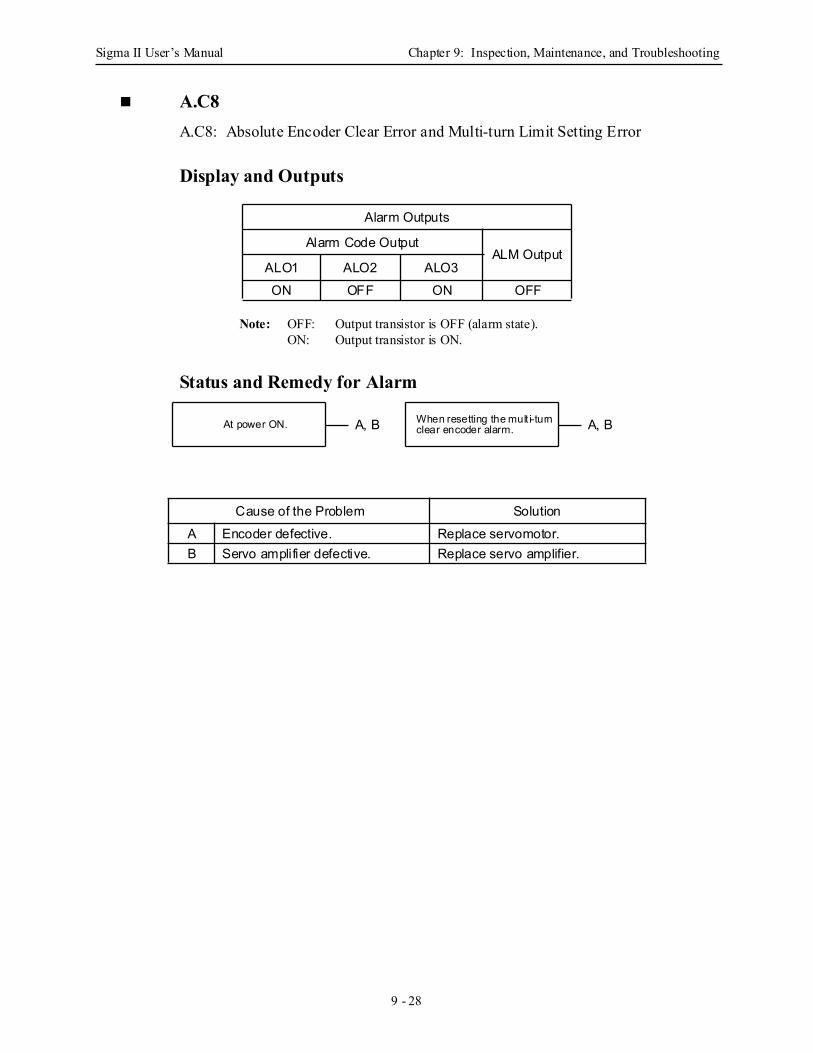
Sigma II User’s Manual Chapter 9: Inspection, Maintenance, and Troubleshooting
9 - 28
A.C8A.C8: Absolute Encoder Clear Error and Multi-turn Limit Setting Error
Display and Outputs
Note: OFF: Output transistor is OFF (alarm state).ON: Output transistor is ON.
Status and Remedy for Alarm
Alarm Outputs
Alarm Code OutputALM Output
ALO1 ALO2 ALO3ON OFF ON OFF
Cause of the Problem SolutionA Encoder defective. Replace servomotor.B Servo amplifier defective. Replace servo amplifier.
At power ON. When resetting the mult i-turnclear encoder alarm. A, BA, B
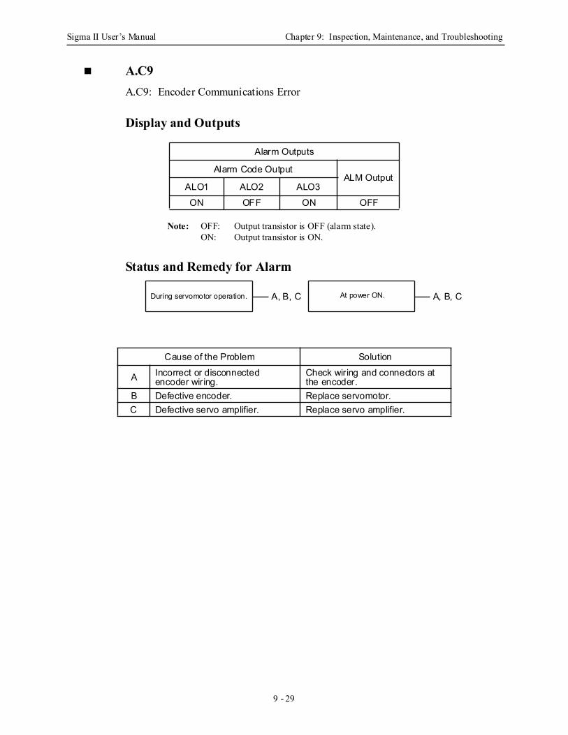
Sigma II User’s Manual Chapter 9: Inspection, Maintenance, and Troubleshooting
9 - 29
A.C9A.C9: Encoder Communications Error
Display and Outputs
Note: OFF: Output transistor is OFF (alarm state).ON: Output transistor is ON.
Status and Remedy for Alarm
Alarm Outputs
Alarm Code OutputALM Output
ALO1 ALO2 ALO3ON OFF ON OFF
Cause of the Problem Solution
A Incorrect or disconnected encoder wiring.
Check wiring and connectors at the encoder.
B Defective encoder. Replace servomotor.C Defective servo amplifier. Replace servo amplifier.
During servomotor operation. At power ON. A, B, CA, B, C
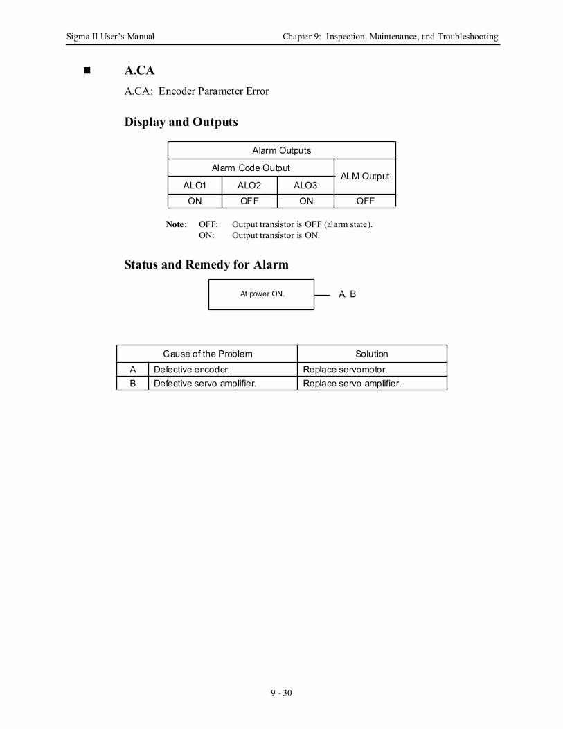
Sigma II User’s Manual Chapter 9: Inspection, Maintenance, and Troubleshooting
9 - 30
A.CAA.CA: Encoder Parameter Error
Display and Outputs
Note: OFF: Output transistor is OFF (alarm state).ON: Output transistor is ON.
Status and Remedy for Alarm
Alarm Outputs
Alarm Code OutputALM Output
ALO1 ALO2 ALO3ON OFF ON OFF
Cause of the Problem SolutionA Defective encoder. Replace servomotor.B Defective servo amplifier. Replace servo amplifier.
At power ON. A, B

Sigma II User’s Manual Chapter 9: Inspection, Maintenance, and Troubleshooting
9 - 31
A.CbA.Cb: Encoder Echoback Error
Display and Outputs
Note: OFF: Output transistor is OFF (alarm state).ON: Output transistor is ON.
Status and Remedy for Alarm
Alarm Outputs
Alarm Code OutputALM Output
ALO1 ALO2 ALO3ON OFF ON OFF
Cause of the Problem Solution
A Incorrect or disconnected encoder wiring.
Check wiring and connectors at encoder.
B Defective encoder. Replace servomotor.C Defective servo amplifier. Replace servo amplifier.
At power ON. A, B
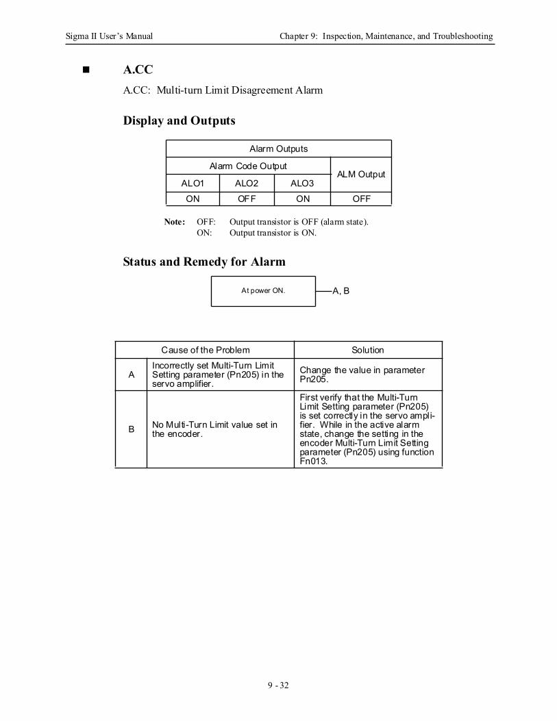
Sigma II User’s Manual Chapter 9: Inspection, Maintenance, and Troubleshooting
9 - 32
A.CCA.CC: Multi-turn Limit Disagreement Alarm
Display and Outputs
Note: OFF: Output transistor is OFF (alarm state).ON: Output transistor is ON.
Status and Remedy for Alarm
Alarm Outputs
Alarm Code OutputALM Output
ALO1 ALO2 ALO3ON OFF ON OFF
Cause of the Problem Solution
AIncorrectly set Multi-Turn Limit Setting parameter (Pn205) in the servo amplifier.
Change the value in parameter Pn205.
B No Multi-Turn Limit value set in the encoder.
First verify that the Multi-Turn Limit Setting parameter (Pn205) is set correctly in the servo ampli-fier. While in the active alarm state, change the setting in the encoder Multi-Turn Limit Setting parameter (Pn205) using function Fn013.
At power ON. A, B
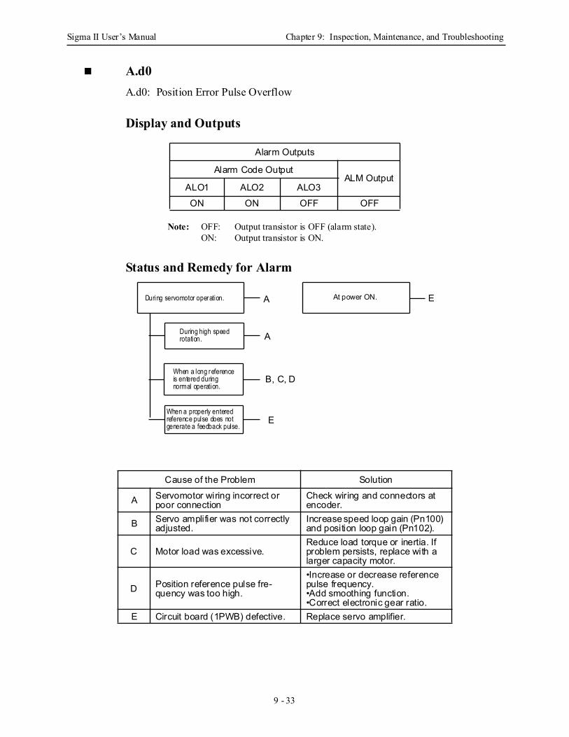
Sigma II User’s Manual Chapter 9: Inspection, Maintenance, and Troubleshooting
9 - 33
A.d0A.d0: Position Error Pulse Overflow
Display and Outputs
Note: OFF: Output transistor is OFF (alarm state).ON: Output transistor is ON.
Status and Remedy for Alarm
Alarm Outputs
Alarm Code OutputALM Output
ALO1 ALO2 ALO3ON ON OFF OFF
Cause of the Problem Solution
A Servomotor wiring incorrect or poor connection
Check wiring and connectors at encoder.
B Servo amplifier was not correctly adjusted.
Increase speed loop gain (Pn100) and position loop gain (Pn102).
C Motor load was excessive.Reduce load torque or inertia. If problem persists, replace with a larger capacity motor.
D Position reference pulse fre-quency was too high.
•Increase or decrease reference pulse frequency.•Add smoothing function.•Correct electronic gear ratio.
E Circuit board (1PWB) defective. Replace servo amplifier.
EADuring servomotor operation.
During high speed
When a long reference
rotation.
is entered duringnormal operation.
When a properly enteredreference pulse does notgenerate a feedback pulse.
At power ON.
A
B, C, D
E
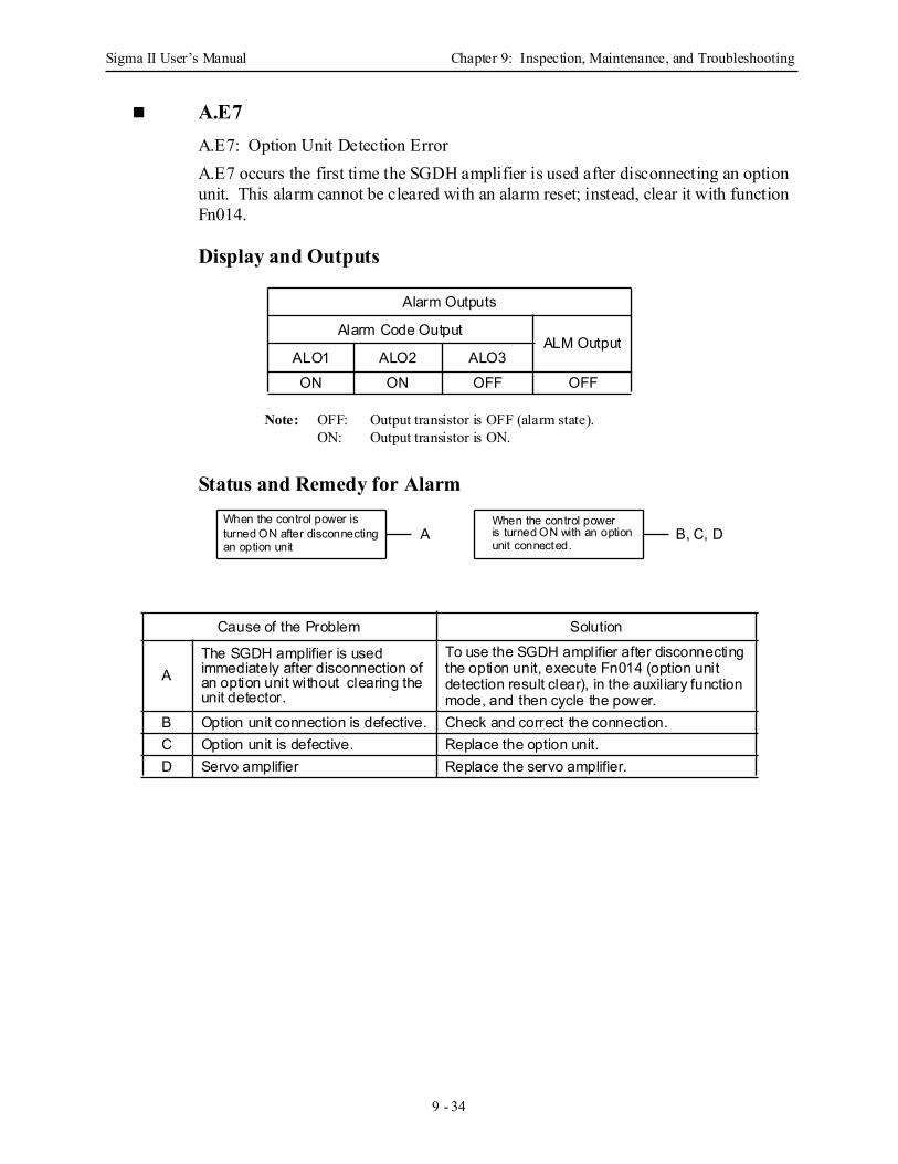
Sigma II User’s Manual Chapter 9: Inspection, Maintenance, and Troubleshooting
9 - 34
A.E7 A.E7: Option Unit Detection ErrorA.E7 occurs the first time the SGDH amplifier is used after disconnecting an option unit. This alarm cannot be cleared with an alarm reset; instead, clear it with function Fn014.
Display and Outputs
Note: OFF: Output transistor is OFF (alarm state).ON: Output transistor is ON.
Status and Remedy for Alarm
Alarm Outputs
Alarm Code OutputALM Output
ALO1 ALO2 ALO3ON ON OFF OFF
Cause of the Problem Solution
AThe SGDH amplifier is used immediately after disconnection of an option unit without clearing the unit detector.
To use the SGDH amplifier after disconnecting the option unit, execute Fn014 (option unit detection result clear), in the auxil iary function mode, and then cycle the power.
B Option unit connection is defective. Check and correct the connection.C Option unit is defective. Replace the option unit.D Servo amplifier Replace the servo amplifier.
When the control power isturned ON after disconnecting
When the control poweris turned ON with an option
an option unit unit connected.B, C, DA
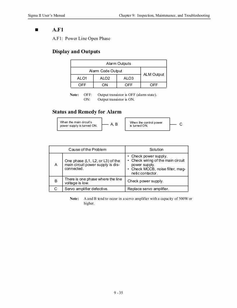
Sigma II User’s Manual Chapter 9: Inspection, Maintenance, and Troubleshooting
9 - 35
A.F1A.F1: Power Line Open Phase
Display and Outputs
Note: OFF: Output transistor is OFF (alarm state).ON: Output transistor is ON.
Status and Remedy for Alarm
Note: A and B tend to occur in a servo amplifier with a capacity of 500W or higher.
Alarm Outputs
Alarm Code OutputALM Output
ALO1 ALO2 ALO3OFF ON OFF OFF
Cause of the Problem Solution
AOne phase (L1, L2, or L3) of the main circuit power supply is dis-connected.
• Check power supply.• Check wiring of the main circuit
power supply.• Check MCCB, noise filter, mag-
netic contactor.
B There is one phase where the line voltage is low. Check power supply.
C Servo amplifier defective. Replace servo amplifier.
When the main circuit’spower supply is turned ON.
When the control poweris turned ON. CA, B
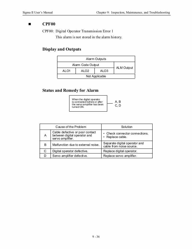
Sigma II User’s Manual Chapter 9: Inspection, Maintenance, and Troubleshooting
9 - 36
CPF00CPF00: Digital Operator Transmission Error 1
This alarm is not stored in the alarm history.
Display and Outputs
Status and Remedy for Alarm
Alarm Outputs
Alarm Code OutputALM Output
ALO1 ALO2 ALO3Not Applicable
Cause of the Problem Solution
ACable defective or poor contact between digital operator and servo amplifier.
• Check connector connections.• Replace cable.
B Malfunction due to external noise. Separate digital operator and cable from noise source.
C Digital operator defective. Replace digital operator.D Servo amplifier defective. Replace servo amplifier.
When the digital operatoris connected before or afterthe servo amplifier has beenturned ON.
A, BC, D
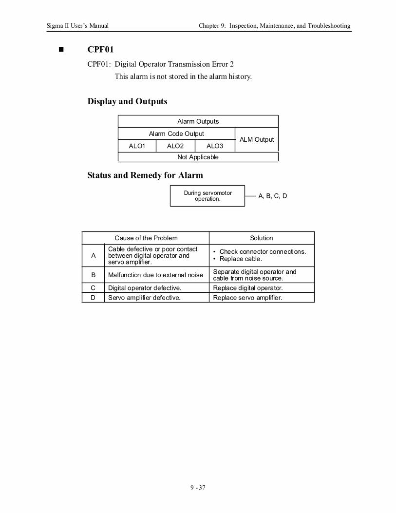
Sigma II User’s Manual Chapter 9: Inspection, Maintenance, and Troubleshooting
9 - 37
CPF01CPF01: Digital Operator Transmission Error 2
This alarm is not stored in the alarm history.
Display and Outputs
Status and Remedy for Alarm
Alarm Outputs
Alarm Code OutputALM Output
ALO1 ALO2 ALO3Not Applicable
Cause of the Problem Solution
ACable defective or poor contact between digital operator and servo amplifier.
• Check connector connections.• Replace cable.
B Malfunction due to external noise Separate digital operator and cable from noise source.
C Digital operator defective. Replace digital operator.D Servo amplifier defective. Replace servo amplifier.
During servomotoroperation. A, B, C, D

Sigma II User’s Manual Chapter 9: Inspection, Maintenance, and Troubleshooting
9 - 38
A.- -A.- -: Normal Operation This is not an alarm display.
Display and Outputs
Note: OFF: Output transistor is OFF (alarm state).ON: Output transistor is ON.
Alarm Outputs
Alarm Code OutputALM Output
ALO1 ALO2 ALO3OFF OFF OFF ON
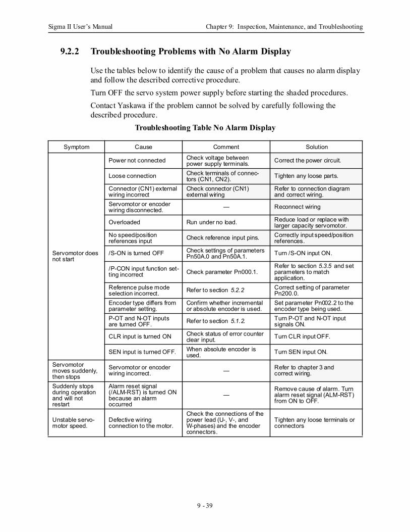
Sigma II User’s Manual Chapter 9: Inspection, Maintenance, and Troubleshooting
9 - 39
9.2.2 Troubleshooting Problems with No Alarm Display
Use the tables below to identify the cause of a problem that causes no alarm display and follow the described corrective procedure. Turn OFF the servo system power supply before starting the shaded procedures.Contact Yaskawa if the problem cannot be solved by carefully following the described procedure.
Troubleshooting Table No Alarm Display
Symptom Cause Comment Solution
Servomotor does not start
Power not connected Check voltage between power supply terminals. Correct the power circuit.
Loose connection Check terminals of connec-tors (CN1, CN2). Tighten any loose parts.
Connector (CN1) external wiring incorrect
Check connector (CN1) external wiring
Refer to connection diagram and correct wiring.
Servomotor or encoder wiring disconnected. — Reconnect wiring
Overloaded Run under no load. Reduce load or replace with larger capacity servomotor.
No speed/position references input Check reference input pins. Correctly input speed/position
references.
/S-ON is turned OFF Check settings of parameters Pn50A.0 and Pn50A.1. Turn /S-ON input ON.
/P-CON input function set-ting incorrect Check parameter Pn000.1.
Refer to section 5.3.5 and set parameters to match application.
Reference pulse mode selection incorrect. Refer to section 5.2.2 Correct setting of parameter
Pn200.0.Encoder type differs from parameter setting.
Confirm whether incremental or absolute encoder is used.
Set parameter Pn002.2 to the encoder type being used.
P-OT and N-OT inputs are turned OFF. Refer to section 5.1.2. Turn P-OT and N-OT input
signals ON.
CLR input is turned ON Check status of error counter clear input. Turn CLR input OFF.
SEN input is turned OFF. When absolute encoder is used. Turn SEN input ON.
Servomotor moves suddenly, then stops
Servomotor or encoder wiring incorrect. — Refer to chapter 3 and
correct wiring.
Suddenly stops during operation and will not restart
Alarm reset signal (/ALM-RST) is turned ON because an alarm occurred
—Remove cause of alarm. Turn alarm reset signal (ALM-RST) from ON to OFF.
Unstable servo-motor speed.
Defective wiring connection to the motor.
Check the connections of the power lead (U-, V-, and W-phases) and the encoder connectors.
Tighten any loose terminals or connectors
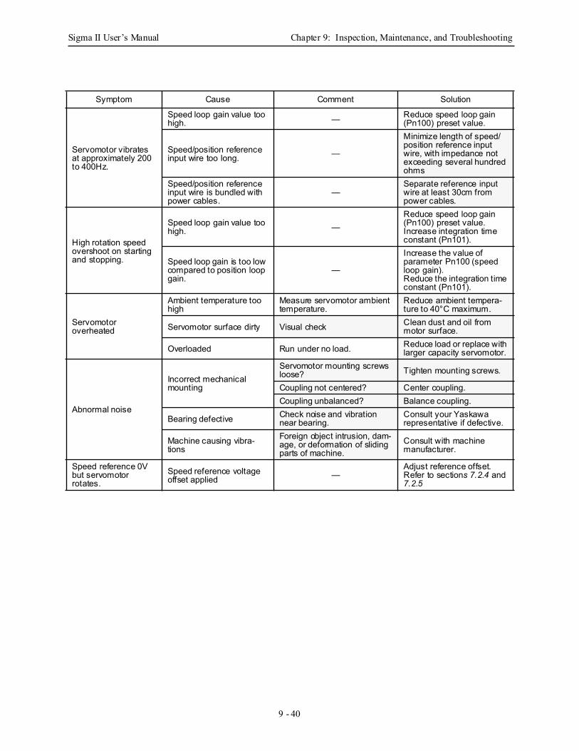
Sigma II User’s Manual Chapter 9: Inspection, Maintenance, and Troubleshooting
9 - 40
Symptom Cause Comment Solution
Servomotor vibrates at approximately 200 to 400Hz.
Speed loop gain value too high. — Reduce speed loop gain
(Pn100) preset value.
Speed/position reference input wire too long. —
Minimize length of speed/position reference input wire, with impedance not exceeding several hundred ohms
Speed/position reference input wire is bundled with power cables.
—Separate reference input wire at least 30cm from power cables.
High rotation speed overshoot on starting and stopping.
Speed loop gain value too high. —
Reduce speed loop gain (Pn100) preset value.Increase integration time constant (Pn101).
Speed loop gain is too low compared to position loop gain.
—
Increase the value of parameter Pn100 (speed loop gain).Reduce the integration time constant (Pn101).
Servomotor overheated
Ambient temperature too high
Measure servomotor ambient temperature.
Reduce ambient tempera-ture to 40°C maximum.
Servomotor surface dirty Visual check Clean dust and oil from motor surface.
Overloaded Run under no load. Reduce load or replace with larger capacity servomotor.
Abnormal noise
Incorrect mechanical mounting
Servomotor mounting screws loose? Tighten mounting screws.
Coupling not centered? Center coupling.Coupling unbalanced? Balance coupling.
Bearing defective Check noise and vibration near bearing.
Consult your Yaskawa representative if defective.
Machine causing vibra-tions
Foreign object intrusion, dam-age, or deformation of sliding parts of machine.
Consult with machine manufacturer.
Speed reference 0V but servomotor rotates.
Speed reference voltage offset applied —
Adjust reference offset. Refer to sections 7.2.4 and 7.2.5
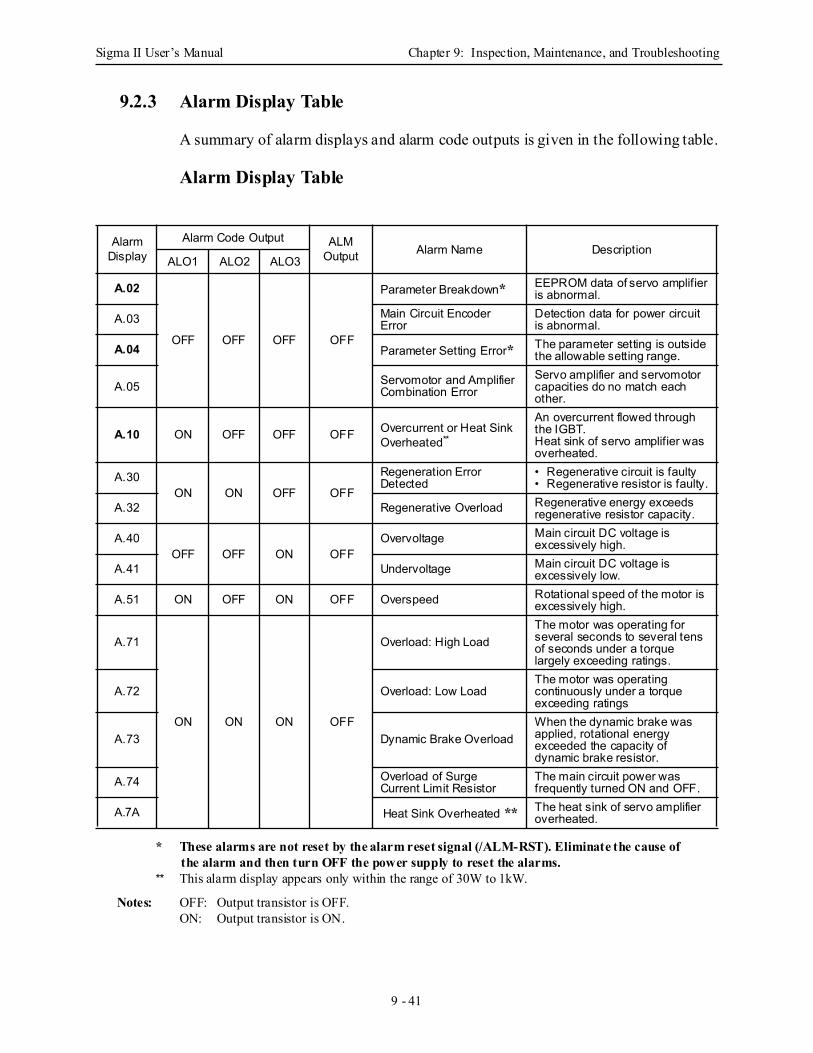
Sigma II User’s Manual Chapter 9: Inspection, Maintenance, and Troubleshooting
9 - 41
9.2.3 Alarm Display Table
A summary of alarm displays and alarm code outputs is given in the following table.
Alarm Display Table
* These alarms are not reset by the alarm reset signal (/ALM-RST). Eliminate the cause of the alarm and then turn OFF the power supply to reset the alarms.
** This alarm display appears only within the range of 30W to 1kW.
Notes: OFF: Output transistor is OFF.ON: Output transistor is ON.
Alarm Display
Alarm Code Output ALMOutput Alarm Name Description
ALO1 ALO2 ALO3
A.02
OFF OFF OFF OFF
Parameter Breakdown* EEPROM data of servo amplifier is abnormal.
A.03 Main Circuit Encoder Error
Detection data for power circuit is abnormal.
A.04 Parameter Setting Error* The parameter setting is outside the allowable setting range.
A.05 Servomotor and Amplifier Combination Error
Servo amplifier and servomotor capacities do no match each other.
A.10 ON OFF OFF OFF Overcurrent or Heat Sink Overheated**
An overcurrent flowed through the IGBT.Heat sink of servo amplifier was overheated.
A.30ON ON OFF OFF
Regeneration Error Detected
• Regenerative circuit is faulty• Regenerative resistor is faulty.
A.32 Regenerative Overload Regenerative energy exceeds regenerative resistor capacity.
A.40OFF OFF ON OFF
Overvoltage Main circuit DC voltage is excessively high.
A.41 Undervoltage Main circuit DC voltage is excessively low.
A.51 ON OFF ON OFF Overspeed Rotational speed of the motor is excessively high.
A.71
ON ON ON OFF
Overload: High LoadThe motor was operating for several seconds to several tens of seconds under a torque largely exceeding ratings.
A.72 Overload: Low LoadThe motor was operating continuously under a torque exceeding ratings
A.73 Dynamic Brake OverloadWhen the dynamic brake was applied, rotational energy exceeded the capacity of dynamic brake resistor.
A.74 Overload of Surge Current Limit Resistor
The main circuit power was frequently turned ON and OFF.
A.7A Heat Sink Overheated ** The heat sink of servo amplifier overheated.
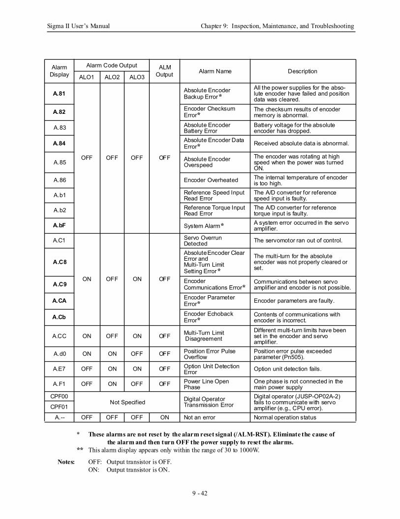
Sigma II User’s Manual Chapter 9: Inspection, Maintenance, and Troubleshooting
9 - 42
* These alarms are not reset by the alarm reset signal (/ALM-RST). Eliminate the cause of
the alarm and then turn OFF the power supply to reset the alarms.** This alarm display appears only within the range of 30 to 1000W.
Notes: OFF: Output transistor is OFF.
ON: Output transistor is ON.
Alarm Display
Alarm Code Output ALMOutput Alarm Name Description
ALO1 ALO2 ALO3
A.81
OFF OFF OFF OFF
Absolute Encoder Backup Error*
All the power supplies for the abso-lute encoder have failed and position data was cleared.
A.82 Encoder Checksum Error*
The checksum results of encoder memory is abnormal.
A.83 Absolute Encoder Battery Error
Battery voltage for the absolute encoder has dropped.
A.84 Absolute Encoder Data Error* Received absolute data is abnormal.
A.85 Absolute Encoder Overspeed
The encoder was rotating at high speed when the power was turned ON.
A.86 Encoder Overheated The internal temperature of encoder is too high.
A.b1 Reference Speed Input Read Error
The A/D converter for reference speed input is faulty.
A.b2 Reference Torque Input Read Error
The A/D converter for reference torque input is faulty.
A.bF System Alarm* A system error occurred in the servo amplifier.
A.C1
ON OFF ON OFF
Servo Overrun Detected The servomotor ran out of control.
A.C8Absolute Encoder Clear Error and Multi-Turn Limit Setting Error*
The multi-turn for the absolute encoder was not properly cleared or set.
A.C9 Encoder Communications Error*
Communications between servo amplifier and encoder is not possible.
A.CA Encoder Parameter Error* Encoder parameters are faulty.
A.Cb Encoder Echoback Error*
Contents of communications with encoder is incorrect.
A.CC ON OFF ON OFF Multi-Turn Limit Disagreement
Different multi-turn limits have been set in the encoder and servo amplifier.
A.d0 ON ON OFF OFF Position Error Pulse Overflow
Position error pulse exceeded parameter (Pn505).
A.E7 OFF ON ON OFF Option Unit Detection Error Option unit detection fails.
A.F1 OFF ON OFF OFF Power Line Open Phase
One phase is not connected in the main power supply
CPF00Not Specified Digital Operator
Transmission Error Digital operator (JUSP-OP02A-2) fails to communicate with servo amplifier (e.g., CPU error).CPF01
A.-- OFF OFF OFF ON Not an error Normal operation status
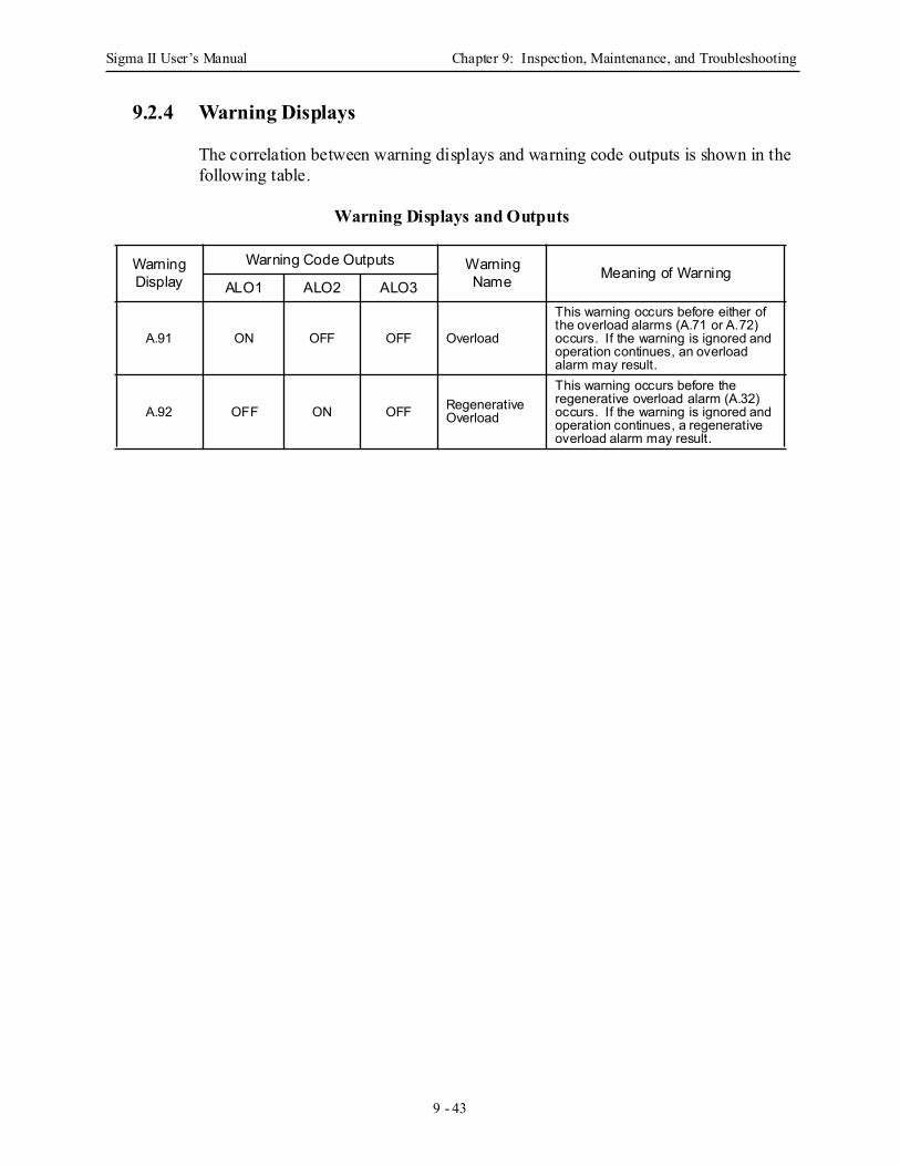
Sigma II User’s Manual Chapter 9: Inspection, Maintenance, and Troubleshooting
9 - 43
9.2.4 Warning Displays
The correlation between warning displays and warning code outputs is shown in the following table.
Warning Displays and Outputs
Warning Display
Warning Code Outputs Warning Name Meaning of Warning
ALO1 ALO2 ALO3
A.91 ON OFF OFF Overload
This warning occurs before either of the overload alarms (A.71 or A.72) occurs. If the warning is ignored and operation continues, an overload alarm may result.
A.92 OFF ON OFF Regenerative Overload
This warning occurs before the regenerative overload alarm (A.32) occurs. If the warning is ignored and operation continues, a regenerative overload alarm may result.
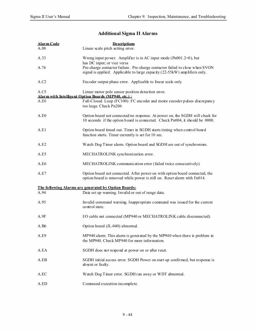
Sigma II User’s Manual Chapter 9: Inspection, Maintenance, and Troubleshooting
9 - 44
Additional Sigma II Alarms Alarm Code Descriptions A.08 Linear scale pitch setting error. A.33 Wrong input power. Amplifier is in AC input mode (Pn001.2=0), but
has DC input; or vice versa A.76 Pre-charge contactor failure. Pre-charge contactor failed to close when SVON
signal is applied. Applicable to large capacity (22-55kW) amplifiers only.
A.C2 Encoder output phase error. Applicable to linear scale only A.C5 Linear motor pole sensor position detection error. Alarm with Intelligent Option Boards (MP940, etc.) : A.D1 Full-Closed Loop (FC100): FC encoder and motor encoder pulses discrepancy
too large. Check Pn206 A.E0 Option board not connected/no response. At power on, the SGDH will check for
10 seconds if the option board is connected. Check Pn004, it should be 0000. A.E1 Option board timed out. Timer in SGDH starts timing when control board
function starts. Timer currently is set for 10 sec. A.E2 Watch Dog Timer alarm. Option board and SGDH are out of synchronism. A.E5 MECHATROLINK synchronization error. A.E6 MECHATROLINK communication error (failed twice consecutively). A.E7 Option board not connected. After power on with option board connected, the
option board is removed while power is still on. Reset alarm with Fn014. The following Alarms are generated by Option Boards: A.94 Data set up warning. Invalid or out of range data. A.95 Invalid command warning. Inappropriate command was issued for the current
control state. A.9F I/O cable not connected (MP940 or MECHATROLINK cable disconnected). A.B6 Option board (JL-040) abnormal. A.E9 MP940 alarm. This alarm is generated by the MP940 when there is problem in
the MP940. Check MP940 for more information. A.EA SGDH does not respond at power on or after reset. A.EB SGDH initial access error. SGDH Power on start up confirmed, but response is
absent or faulty. A.EC Watch Dog Timer error. SGDH ran away or WDT abnormal. A.ED Command execution incomplete.
Sigma II User’s Manual Appendix A: Host Controller Connection Examples
A - 1
A Host Controller Connection ExamplesThis appendix provides examples SGDH servo amplifiers con-nected to typical host controllers. Refer to the manuals for the host controller when actually connecting to them.
A.1 Connecting the GL-series MC20 Motion Module .............................................. A-2
A.2 Connecting the CP-9200SH Servo Controller Module (SVA) ........................... A-3
A.3 Connecting the GL-series B2813 Positioning Module ....................................... A-4
A.4 Connecting OMRON's C500-NC221 Position Control Unit .............................. A-5
A.5 Connecting OMRON's C500-NC112 Position Control Unit .............................. A-6
A.6 Connecting MITSUBISHI's AD72 Positioning Unit .......................................... A-7
A.7 Connecting MITSUBISHI's AD75 Positioning Unit .......................................... A-8
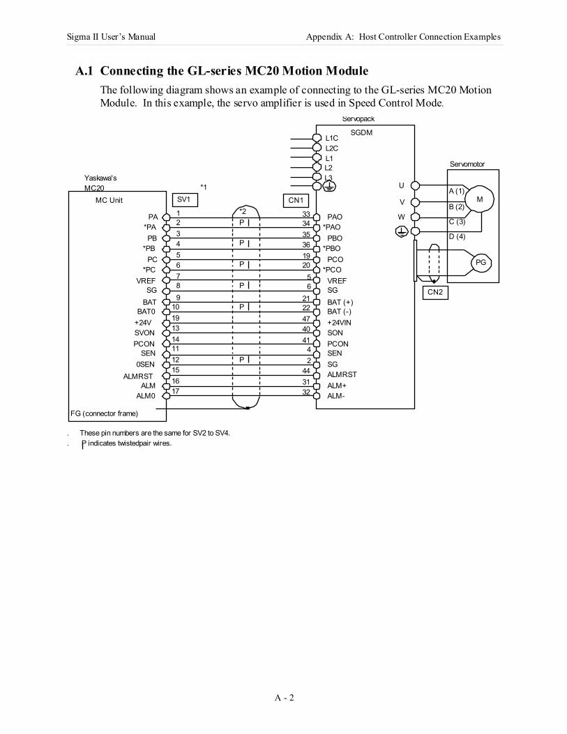
Sigma II User’s Manual Appendix A: Host Controller Connection Examples
A - 2
A.1 Connecting the GL-series MC20 Motion ModuleThe following diagram shows an example of connecting to the GL-series MC20 Motion Module. In this example, the servo amplifier is used in Speed Control Mode.
M
PG
Yaskawa's MC20
Servopack
SGDML1C
W
V
UL3L2L1L2C
P
CN1
PA PAO1 33
*PAO2 34
PB PBO3 35
*PBO4 36
PC PCO5 19
*PCO6 20
VREF VREF7 5
SG SG8 6
BAT BAT (+)9 21
BAT0 BAT (-)10 22
+24V +24VIN19 47
SVON SON13 40
PCON PCON14 41
SEN SEN11 412 20SEN SG
ALMRST15 44
ALM ALM+ALM0 ALM-17 32
P
P
SV1
3116ALMRST
*1
FG (connector frame)
MC Unit
PCN2
Servomotor
A (1)
B (2)
C (3)
D (4)*PA
*PB
*PC
*2
. These pin numbers are the same for SV2 to SV4.
. P indicates twistedpair wires.
P
P
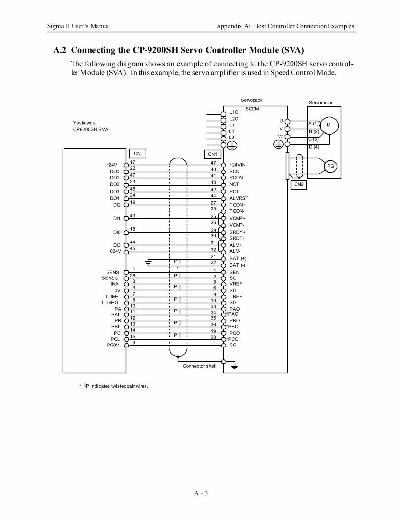
Sigma II User’s Manual Appendix A: Host Controller Connection Examples
A - 3
A.2 Connecting the CP-9200SH Servo Controller Module (SVA)The following diagram shows an example of connecting to the CP-9200SH servo control-ler Module (SVA). In this example, the servo amplifier is used in Speed Control Mode.
* P indicates twistedpair wires.
CN1
+24V +24VIN17 47
DO0 SON22 40
DO1 PCON47 41
DO2 NOT23 43
DO3 POT48 42
DO4 ALMRST24 44
DI2 TGON+19 27
TGON-28
DI1 VCMP+43 25
VCMP-26
DI0 SRDY+18 29
SRDT-30
DI3 ALM+44 31
024V ALM-45 3221 BAT (+)
BAT (-)22
SENS SENSENSG SG26 2
CN
41
TLIMPGPA
TLIMP0V
INA
PG0VPCL
PCPBL
PBPAL
91514131211108743
SG
PCO
PBO
TREFSGVREF
SGPAO
193635343310965
201
Connector shell
*
Yaskawa's CP9200SH SVA
M
PG
WVU
CN2
Servomotor
A (1)B (2)C (3)D (4)
Servopack
SGDML1C
L3L2L1L2C
P
P
P
P
P
P
P*PCO
*PBO
*PAO
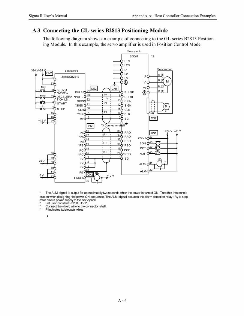
Sigma II User’s Manual Appendix A: Host Controller Connection Examples
A - 4
A.3 Connecting the GL-series B2813 Positioning ModuleThe following diagram shows an example of connecting to the GL-series B2813 Position-ing Module. In this example, the servo amplifier is used in Position Control Mode.
1Ry
CN2
CN1
M
PG
CN2
CN1
024 V+24 V
+12 V
+5 V
0 VERROR
FG
PA
PB
0V
PC
Yaskawa's
JAMSCB2813
SERVO NORMALDECELERATION LSSTART
STOP
Servopack
W
V
PAO
SG
PCO
PBO+24VIN
SON
POT
NOT
ALM+
ALM-
A (1)
B (2)
C (3)
D (4)
+24 V
3Ry
4Ry
1
33
35
20
474645
2
3
4948
121110
50
19
181716
3
21
1514
36
20
+12 V
1936
35
201
3433
43
42
40
47
32
31
P
P
P
P
P
P
CN1CN2PULSE
0V
CLR
SIGN
PULSE
SG
CLR
SIGN
24
65
3821
2223
2141512
1187
*1
*2
2Ry
L1C
L3L2L1
L2C
U
SGDM
1Ry
*3 Connector shell
CN2
Servomotor
*4*PULSE
*CLR
*SIGN
*PA
*PB
*PC
0V0V
*PULSE
*CLR
*SIGN
*PAO
*PCO
*PBO
024 V
* . The ALM signal is output for approximately two seconds when the power is turned ON. Take this into consideration when designing the power ON sequence. The ALM signal actuates the alarm detection relay 1Ry to stop main circuit power supply to the Servopack.* . Set user constant Pn200.0 to 1".* . Connect the shield wire to the connector shell.* . P indicates twistedpair wires.
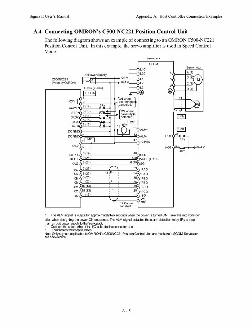
Sigma II User’s Manual Appendix A: Host Controller Connection Examples
A - 5
A.4 Connecting OMRON's C500-NC221 Position Control UnitThe following diagram shows an example of connecting to an OMRON C500-NC221 Position Control Unit. In this example, the servo amplifier is used in Speed Control Mode.
P
P
P
CN2
193635
201
3433
CCWLXSTPXORGXEMGX
DC GNDDC GND
CWLX
XAGXOUT
OUT1X
+24V
0V
XB
XC
XA
+24V +-
I/O Power Supply
EXT INX axis (Y axis)
+24V3Ry
4Ry
M/D
CN1
ALM+
ALM-
VREF (TREF)SG
POT
NOT
3Ry
4RY
3 (13)4 (14)5 (15)6 (16)
1
11
2 (12)98
6 (22)
1 (17)15 (13)16 (14)4 (20)5 (21)
7 (23)
8 (24)9 (25)3 (19)
5 (9)6 (10)
31
32
47
40
43
42
C500NC221(Made by OMRON)
*1
ON when positioning is canceled.
ON when proximity is detected.
1Ry
L1C
L3L2L1
L2C
SON
+24VIN
*2 Connector shell
CN1
Servomotor
*3
11
12
XB
XC
XA
024 V+24 V
PAO
SG
PCO
PBO*PAO
*PCO
*PBO
024 V
M
PG
Servopack
W
V
A (1)B (2)
C (3)
D (4)
U
SGDM
* . The ALM signal is output for approximately two seconds when the power is turned ON. Take this into consideration when designing the power ON sequence. The ALM signal actuates the alarm detection relay 1Ry to stop main circuit power supply to the Servopack.* . Connect the shield wire of the I/O cable to the connector shell.* . P indicates twistedpair wires.Note Only signals applicable to OMRON's C500NC221 Position Control Unit and Yaskawa's SGDM Servopack are shown here.
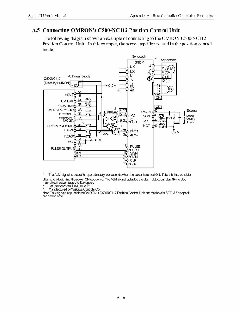
Sigma II User’s Manual Appendix A: Host Controller Connection Examples
A - 6
A.5 Connecting OMRON's C500-NC112 Position Control UnitThe following diagram shows an example of connecting to the OMRON C500-NC112 Position Con trol Unit. In this example, the servo amplifier is used in the position control mode.
CN1
CN2
+-+12V
I/O Power SupplyC500NC112 (Made by OMRON)
+12V
CW LIMITCCW LIMIT
EMERGENCY STOP
ORIGINORIGIN PROXIMITY
LOCAL
READY+5V
PULSE OUTPUT
1A
4A3B3A2B2A1B
10B10A
9B9A8B8A5B
5A4B
4Ry3Ry
1Ry
+5 V
+24V8 7
12V*1
6 LRX01/A2*3
012 V
+24VIN
POTNOT
SON10
9
3132
20
19
15121187
14
47
434240
3Ry +24 V
4Ry1Ry
CN1
0V
EXTERNAL INTERRUPT
Servopack
SGDML1C
L3L2L1L2C
PCO
*PCO
ALM+ALM-
PULSE
CLR
SIGN*PULSE
*CLR
*SIGN
012 V
M
PG
WVU
A (1)B (2)C (3)D (4)
Servomotor
* . The ALM signal is output for approximately two seconds when the power is turned ON. Take this into consideration when designing the power ON sequence. The ALM signal actuates the alarm detection relay 1Ry to stop main circuit power supply to Servopack.* . Set user constant Pn200.0 to 1".* . Manufactured by Yaskawa Controls Co.Note Only signals applicable to OMRON's C500NC112 Position Control Unit and Yaskawa's SGDM Servopack are shown here.
*2
External power supply +24 V*4
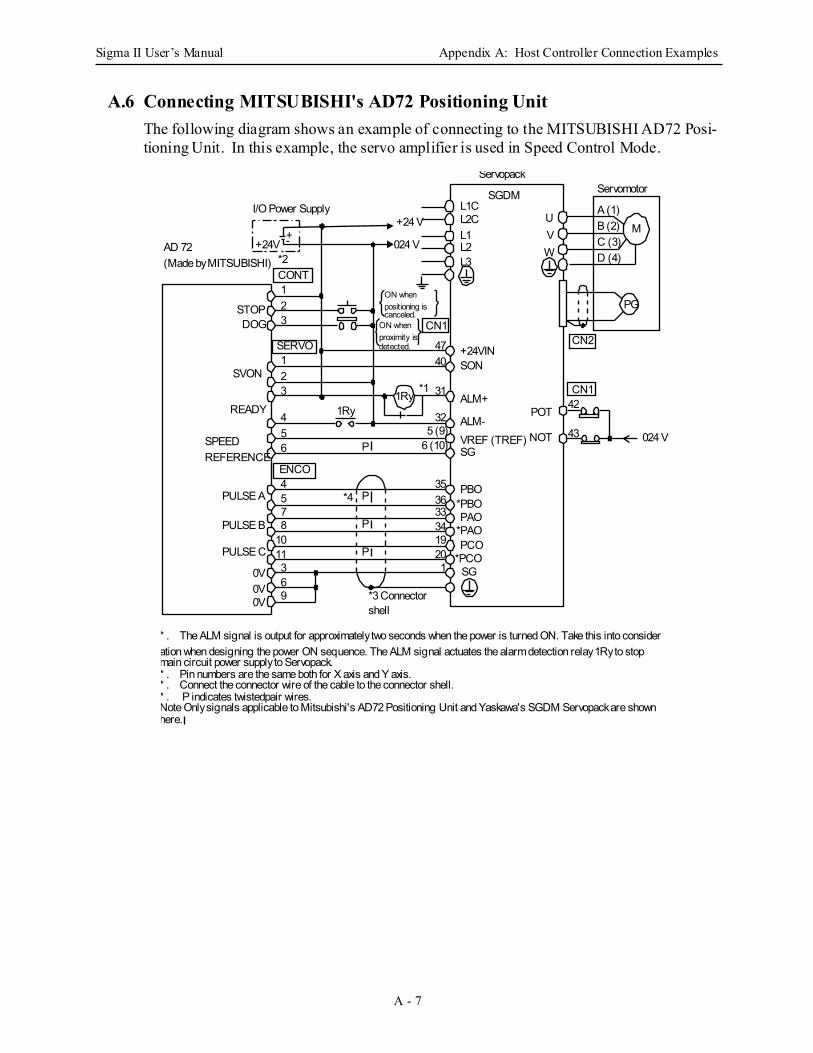
Sigma II User’s Manual Appendix A: Host Controller Connection Examples
A - 7
A.6 Connecting MITSUBISHI's AD72 Positioning UnitThe following diagram shows an example of connecting to the MITSUBISHI AD72 Posi-tioning Unit. In this example, the servo amplifier is used in Speed Control Mode.
+-+24V
I/O Power Supply
024 V
+24 V
CONT
SERVO
CN1
ENCO
P
P
P
L1C
L3L2L1L2C
M
PG
CN1
WVU
A (1)B (2)C (3)D (4)
AD 72 (Made by MITSUBISHI)
SPEED REFERENCE
STOPDOG
SVON
READY
PULSE A
PULSE C
PULSE B
0V
0V0V
*2
1
32
1
32
4
65
4
75
8
1110
3
96
1Ry
P
ON when positioning is canceled.
ON when proximity is detected.
*1
+24VIN
POT
NOT
ALM+
ALM-VREF (TREF)SG
PAO
SG*PCOPCO
*PBOPBO
*PAO
47
32
31
40
1201934333635
5 (9)6 (10)
43
42
SON
*3 Connector shell
1Ry
CN2
*4
024 V
Servopack
SGDM Servomotor
* . The ALM signal is output for approximately two seconds when the power is turned ON. Take this into consideration when designing the power ON sequence. The ALM signal actuates the alarm detection relay 1Ry to stop main circuit power supply to Servopack.* . Pin numbers are the same both for X axis and Y axis.* . Connect the connector wire of the cable to the connector shell.* . P indicates twistedpair wires.Note Only signals applicable to Mitsubishi's AD72 Positioning Unit and Yaskawa's SGDM Servopack are shown here.
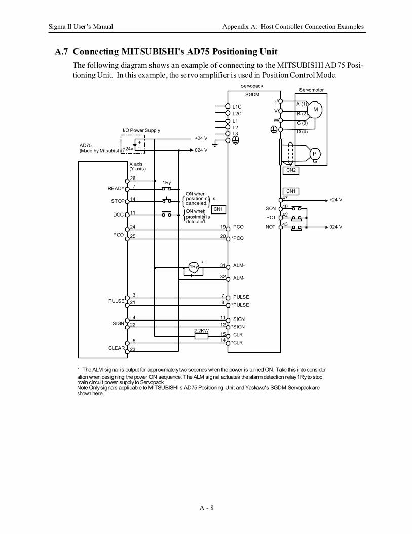
Sigma II User’s Manual Appendix A: Host Controller Connection Examples
A - 8
A.7 Connecting MITSUBISHI's AD75 Positioning UnitThe following diagram shows an example of connecting to the MITSUBISHI AD75 Posi-tioning Unit. In this example, the servo amplifier is used in Position Control Mode.
+-+24v 024 V
1Ry
CN1
CN1
AD75 (Made by Mitsubishi)
STOP
DOG
READY
PGO
PULSE
SIGN
CLEAR
1Ry
*
2.2KW
19
1415
1211
87
32
31
20
42
43
40
47
SON
POT
NOT
25
24
11
14
726
23
5
224
213
+24 V
ON when proximity is detected.
ON when positioning is canceled.
CN2
I/O Power Supply
X axis (Y axis)
L1C
L3L2L1L2C
Servomotor
M
PG
Servopack
W
VA (1)
B (2)
C (3)
D (4)
USGDM
024 V
+24 V
PULSE
CLR
SIGN
*PULSE
*CLR
*SIGN
ALM+
ALM-
PCO
*PCO
* The ALM signal is output for approximately two seconds when the power is turned ON. Take this into consideration when designing the power ON sequence. The ALM signal actuates the alarm detection relay 1Ry to stop main circuit power supply to Servopack.Note Only signals applicable to MITSUBISHI's AD75 Positioning Unit and Yaskawa's SGDM Servopack are shown here.
Sigma II User’s Manual Appendix B: List of Parameters
B - 1
B List of ParametersThis appendix lists the parameters, switches, input signal selections, out put signal selections, auxiliary functions, and monitor modes for SGDH servo amplifiers.
B.1 Parameters ............................................................................................................B-2
B.2 Switches ...............................................................................................................B-5
B.3 Input Signal Selections ........................................................................................B-9
B.4 Output Signal Selections ....................................................................................B-11
B.5 Auxiliary Functions ...........................................................................................B-12
B.6 Monitor Modes ..................................................................................................B-13
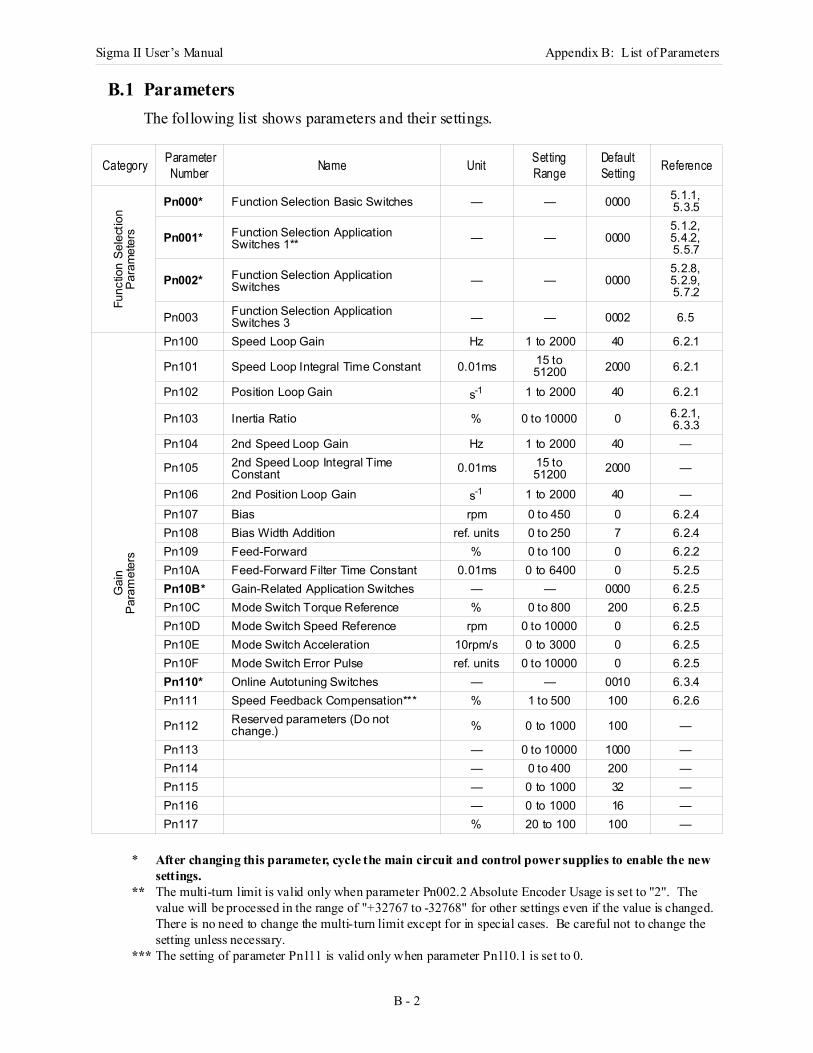
Sigma II User’s Manual Appendix B: List of Parameters
B - 2
B.1 ParametersThe following list shows parameters and their settings.
Category Parameter Number Name Unit Setting
RangeDefault Setting Reference
Func
tion
Sele
ctio
n Pa
ram
eter
s
Pn000* Function Selection Basic Switches — — 0000 5.1.1,5.3.5
Pn001* Function Selection Application Switches 1** — — 0000
5.1.2,5.4.2,5.5.7
Pn002* Function Selection Application Switches — — 0000
5.2.8,5.2.9,5.7.2
Pn003 Function Selection Application Switches 3 — — 0002 6.5
Gai
nPa
ram
eter
s
Pn100 Speed Loop Gain Hz 1 to 2000 40 6.2.1
Pn101 Speed Loop Integral Time Constant 0.01ms 15 to 51200 2000 6.2.1
Pn102 Position Loop Gain s-1 1 to 2000 40 6.2.1
Pn103 Inertia Ratio % 0 to 10000 0 6.2.1,6.3.3
Pn104 2nd Speed Loop Gain Hz 1 to 2000 40 —
Pn105 2nd Speed Loop Integral Time Constant 0.01ms 15 to
51200 2000 —
Pn106 2nd Position Loop Gain s-1 1 to 2000 40 —Pn107 Bias rpm 0 to 450 0 6.2.4Pn108 Bias Width Addition ref. units 0 to 250 7 6.2.4Pn109 Feed-Forward % 0 to 100 0 6.2.2Pn10A Feed-Forward Filter Time Constant 0.01ms 0 to 6400 0 5.2.5Pn10B* Gain-Related Application Switches — — 0000 6.2.5Pn10C Mode Switch Torque Reference % 0 to 800 200 6.2.5Pn10D Mode Switch Speed Reference rpm 0 to 10000 0 6.2.5Pn10E Mode Switch Acceleration 10rpm/s 0 to 3000 0 6.2.5Pn10F Mode Switch Error Pulse ref. units 0 to 10000 0 6.2.5Pn110* Online Autotuning Switches — — 0010 6.3.4Pn111 Speed Feedback Compensation*** % 1 to 500 100 6.2.6
Pn112 Reserved parameters (Do not change.) % 0 to 1000 100 —
Pn113 — 0 to 10000 1000 —Pn114 — 0 to 400 200 —Pn115 — 0 to 1000 32 —Pn116 — 0 to 1000 16 —Pn117 % 20 to 100 100 —
* After changing this parameter, cycle the main circuit and control power supplies to enable the new settings.
** The multi-turn limit is valid only when parameter Pn002.2 Absolute Encoder Usage is set to "2". The value will be processed in the range of "+32767 to -32768" for other settings even if the value is changed.There is no need to change the multi-turn limit except for in special cases. Be careful not to change the setting unless necessary.
*** The setting of parameter Pn111 is valid only when parameter Pn110.1 is set to 0.
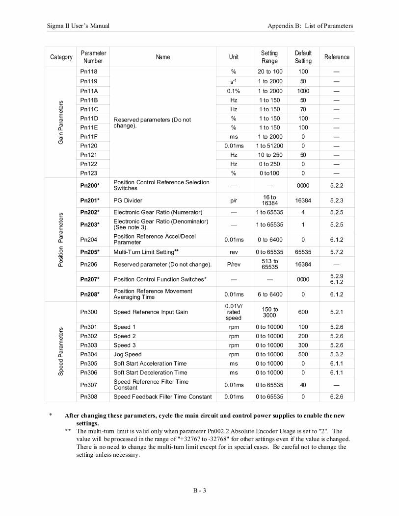
Sigma II User’s Manual Appendix B: List of Parameters
B - 3
Gai
n Pa
ram
eter
s
Pn118
Reserved parameters (Do not change).
% 20 to 100 100 —Pn119 s-1 1 to 2000 50 —Pn11A 0.1% 1 to 2000 1000 —Pn11B Hz 1 to 150 50 —Pn11C Hz 1 to 150 70 —Pn11D % 1 to 150 100 —Pn11E % 1 to 150 100 —Pn11F ms 1 to 2000 0 —Pn120 0.01ms 1 to 51200 0 —Pn121 Hz 10 to 250 50 —Pn122 Hz 0 to 250 0 —Pn123 % 0 to100 0 —
Posit
ion
Par
amet
ers
Pn200* Position Control Reference Selection Switches — — 0000 5.2.2
Pn201* PG Divider p/r 16 to 16384 16384 5.2.3
Pn202* Electronic Gear Ratio (Numerator) — 1 to 65535 4 5.2.5
Pn203* Electronic Gear Ratio (Denominator) (See note 3). — 1 to 65535 1 5.2.5
Pn204 Position Reference Accel/Decel Parameter 0.01ms 0 to 6400 0 6.1.2
Pn205* Multi-Turn Limit Setting** rev 0 to 65535 65535 5.7.2
Pn206 Reserved parameter (Do not change). P/rev 513 to 65535 16384 —
Pn207* Position Control Function Switches* — — 0000 5.2.96.1.2
Pn208* Position Reference Movement Averaging Time 0.01ms 6 to 6400 0 6.1.2
Spee
d Pa
ram
eter
s
Pn300 Speed Reference Input Gain0.01V/ rated speed
150 to 3000 600 5.2.1
Pn301 Speed 1 rpm 0 to 10000 100 5.2.6Pn302 Speed 2 rpm 0 to 10000 200 5.2.6Pn303 Speed 3 rpm 0 to 10000 300 5.2.6Pn304 Jog Speed rpm 0 to 10000 500 5.3.2Pn305 Soft Start Acceleration Time ms 0 to 10000 0 6.1.1Pn306 Soft Start Deceleration Time ms 0 to 10000 0 6.1.1
Pn307 Speed Reference Filter Time Constant 0.01ms 0 to 65535 40 —
Pn308 Speed Feedback Filter Time Constant 0.01ms 0 to 65535 0 6.2.6
* After changing these parameters, cycle the main circuit and control power supplies to enable the new settings.
** The multi-turn limit is valid only when parameter Pn002.2 Absolute Encoder Usage is set to "2". The value will be processed in the range of "+32767 to -32768" for other settings even if the value is changed.There is no need to change the multi-turn limit except for in special cases. Be careful not to change the setting unless necessary.
Category Parameter Number Name Unit Setting
RangeDefault Setting Reference
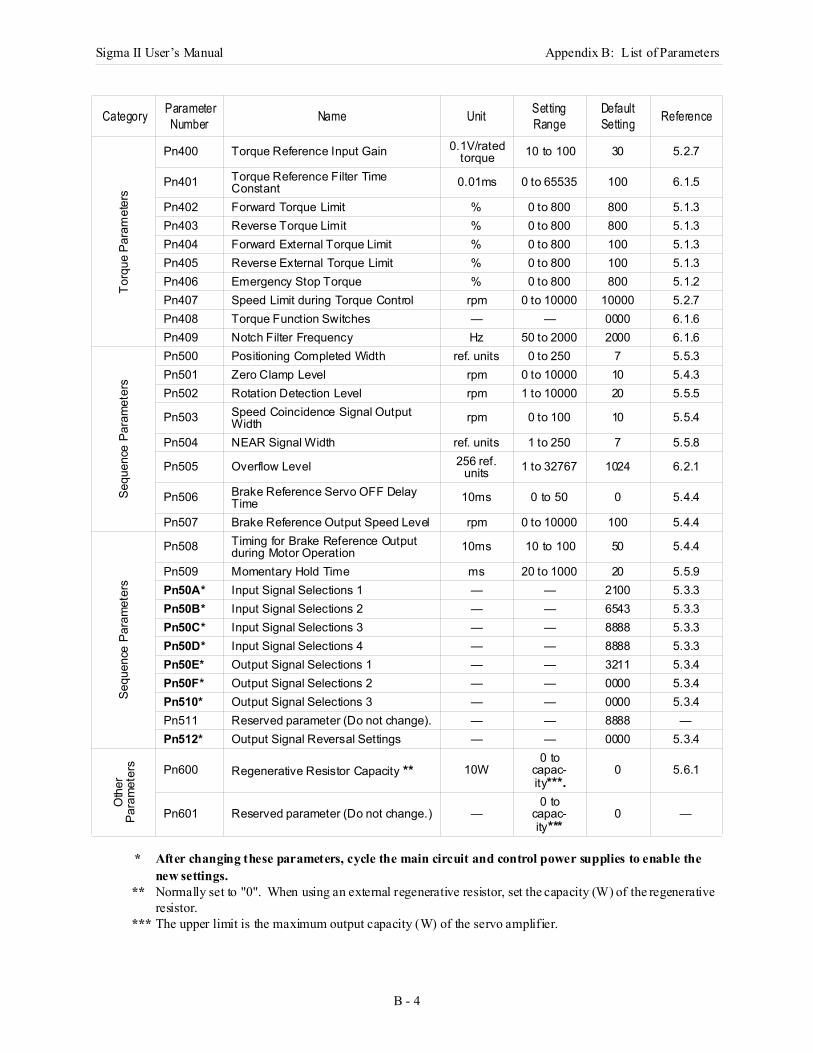
Sigma II User’s Manual Appendix B: List of Parameters
B - 4
* After changing these parameters, cycle the main circuit and control power supplies to enable the new settings.
** Normally set to "0". When using an external regenerative resistor, set the capacity (W) of the regenerative resistor.
*** The upper limit is the maximum output capacity (W) of the servo amplifier.
Torq
ue P
aram
eter
s
Pn400 Torque Reference Input Gain 0.1V/rated torque 10 to 100 30 5.2.7
Pn401 Torque Reference Filter Time Constant 0.01ms 0 to 65535 100 6.1.5
Pn402 Forward Torque Limit % 0 to 800 800 5.1.3Pn403 Reverse Torque Limit % 0 to 800 800 5.1.3Pn404 Forward External Torque Limit % 0 to 800 100 5.1.3Pn405 Reverse External Torque Limit % 0 to 800 100 5.1.3Pn406 Emergency Stop Torque % 0 to 800 800 5.1.2Pn407 Speed Limit during Torque Control rpm 0 to 10000 10000 5.2.7Pn408 Torque Function Switches — — 0000 6.1.6Pn409 Notch Filter Frequency Hz 50 to 2000 2000 6.1.6
Sequ
ence
Par
amet
ers
Pn500 Positioning Completed Width ref. units 0 to 250 7 5.5.3Pn501 Zero Clamp Level rpm 0 to 10000 10 5.4.3Pn502 Rotation Detection Level rpm 1 to 10000 20 5.5.5
Pn503 Speed Coincidence Signal Output Width rpm 0 to 100 10 5.5.4
Pn504 NEAR Signal Width ref. units 1 to 250 7 5.5.8
Pn505 Overflow Level 256 ref. units 1 to 32767 1024 6.2.1
Pn506 Brake Reference Servo OFF Delay Time 10ms 0 to 50 0 5.4.4
Pn507 Brake Reference Output Speed Level rpm 0 to 10000 100 5.4.4
Sequ
ence
Par
amet
ers
Pn508 Timing for Brake Reference Output during Motor Operation 10ms 10 to 100 50 5.4.4
Pn509 Momentary Hold Time ms 20 to 1000 20 5.5.9Pn50A* Input Signal Selections 1 — — 2100 5.3.3Pn50B* Input Signal Selections 2 — — 6543 5.3.3Pn50C* Input Signal Selections 3 — — 8888 5.3.3Pn50D* Input Signal Selections 4 — — 8888 5.3.3Pn50E* Output Signal Selections 1 — — 3211 5.3.4Pn50F* Output Signal Selections 2 — — 0000 5.3.4Pn510* Output Signal Selections 3 — — 0000 5.3.4Pn511 Reserved parameter (Do not change). — — 8888 —Pn512* Output Signal Reversal Settings — — 0000 5.3.4
Oth
erPa
ram
eter
s Pn600 Regenerative Resistor Capacity ** 10W0 to
capac-ity***.
0 5.6.1
Pn601 Reserved parameter (Do not change.) —0 to
capac-ity***
0 —
Category Parameter Number Name Unit Setting
RangeDefault Setting Reference
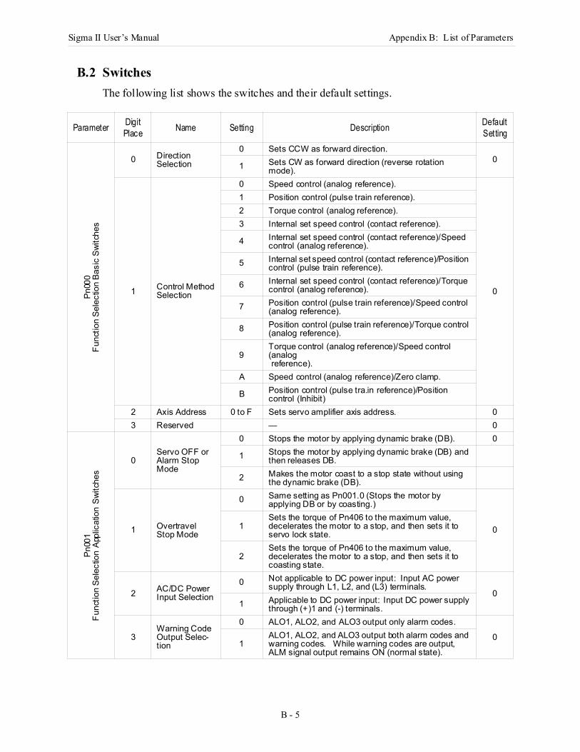
Sigma II User’s Manual Appendix B: List of Parameters
B - 5
B.2 SwitchesThe following list shows the switches and their default settings.
Parameter Digit Place Name Setting Description Default
Setting
Pn00
0Fu
nctio
n Se
lect
ion
Basi
c Sw
itche
s
0 DirectionSelection
0 Sets CCW as forward direction.0
1 Sets CW as forward direction (reverse rotation mode).
1 Control Method Selection
0 Speed control (analog reference).
0
1 Position control (pulse train reference).2 Torque control (analog reference).3 Internal set speed control (contact reference).
4 Internal set speed control (contact reference)/Speed control (analog reference).
5 Internal set speed control (contact reference)/Position control (pulse train reference).
6 Internal set speed control (contact reference)/Torque control (analog reference).
7 Position control (pulse train reference)/Speed control (analog reference).
8 Position control (pulse train reference)/Torque control (analog reference).
9Torque control (analog reference)/Speed control (analog reference).
A Speed control (analog reference)/Zero clamp.
B Position control (pulse tra.in reference)/Position control (Inhibit)
2 Axis Address 0 to F Sets servo amplifier axis address. 03 Reserved — 0
Pn00
1Fu
nctio
n Se
lect
ion
Appl
icat
ion
Switc
hes
0Servo OFF or Alarm Stop Mode
0 Stops the motor by applying dynamic brake (DB). 0
1 Stops the motor by applying dynamic brake (DB) and then releases DB.
2 Makes the motor coast to a stop state without using the dynamic brake (DB).
1 Overtravel Stop Mode
0 Same setting as Pn001.0 (Stops the motor by applying DB or by coasting.)
01Sets the torque of Pn406 to the maximum value, decelerates the motor to a stop, and then sets it to servo lock state.
2Sets the torque of Pn406 to the maximum value, decelerates the motor to a stop, and then sets it to coasting state.
2 AC/DC Power Input Selection
0 Not applicable to DC power input: Input AC power supply through L1, L2, and (L3) terminals.
01 Applicable to DC power input: Input DC power supply
through (+)1 and (-) terminals.
3Warning Code Output Selec-tion
0 ALO1, ALO2, and ALO3 output only alarm codes.
01
ALO1, ALO2, and ALO3 output both alarm codes and warning codes. While warning codes are output, ALM signal output remains ON (normal state).
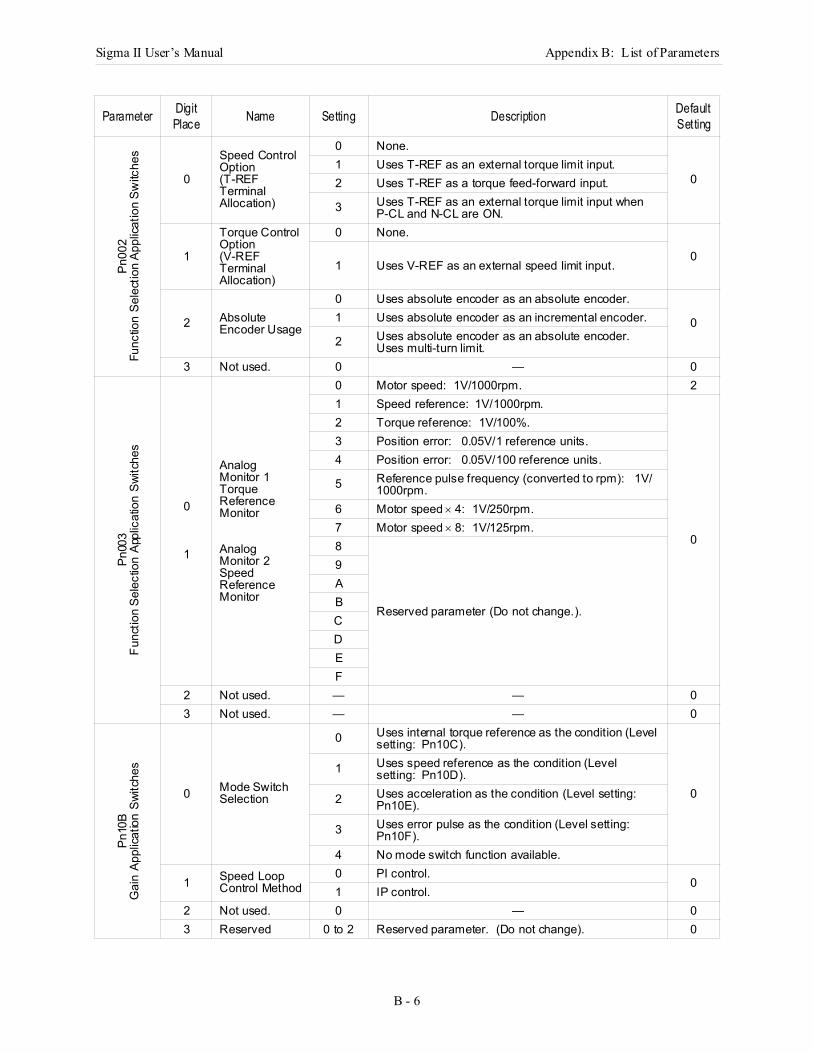
Sigma II User’s Manual Appendix B: List of Parameters
B - 6
Pn00
2Fu
nctio
n Se
lect
ion
Appl
icatio
n Sw
itche
s
0
Speed Control Option (T-REF Terminal Allocation)
0 None.
01 Uses T-REF as an external torque limit input.2 Uses T-REF as a torque feed-forward input.
3 Uses T-REF as an external torque limit input when P-CL and N-CL are ON.
1
Torque Control Option (V-REF Terminal Allocation)
0 None.
01 Uses V-REF as an external speed limit input.
2 Absolute Encoder Usage
0 Uses absolute encoder as an absolute encoder.
01 Uses absolute encoder as an incremental encoder.
2 Uses absolute encoder as an absolute encoder.Uses multi-turn limit.
3 Not used. 0 — 0
Pn00
3Fu
nctio
n Se
lect
ion
Appl
icat
ion
Switc
hes
0
1
Analog Monitor 1Torque Reference Monitor
Analog Monitor 2Speed Reference Monitor
0 Motor speed: 1V/1000rpm. 21 Speed reference: 1V/1000rpm.
0
2 Torque reference: 1V/100%.3 Position error: 0.05V/1 reference units.4 Position error: 0.05V/100 reference units.
5 Reference pulse frequency (converted to rpm): 1V/1000rpm.
6 Motor speed × 4: 1V/250rpm.7 Motor speed × 8: 1V/125rpm.8
Reserved parameter (Do not change.).
9ABCDEF
2 Not used. — — 03 Not used. — — 0
Pn10
BG
ain
Appl
icatio
n Sw
itche
s
0 Mode Switch Selection
0 Uses internal torque reference as the condition (Level setting: Pn10C).
0
1 Uses speed reference as the condition (Level setting: Pn10D).
2 Uses acceleration as the condition (Level setting: Pn10E).
3 Uses error pulse as the condition (Level setting: Pn10F).
4 No mode switch function available.
1 Speed Loop Control Method
0 PI control.0
1 IP control.2 Not used. 0 — 03 Reserved 0 to 2 Reserved parameter. (Do not change). 0
Parameter Digit Place Name Setting Description Default
Setting
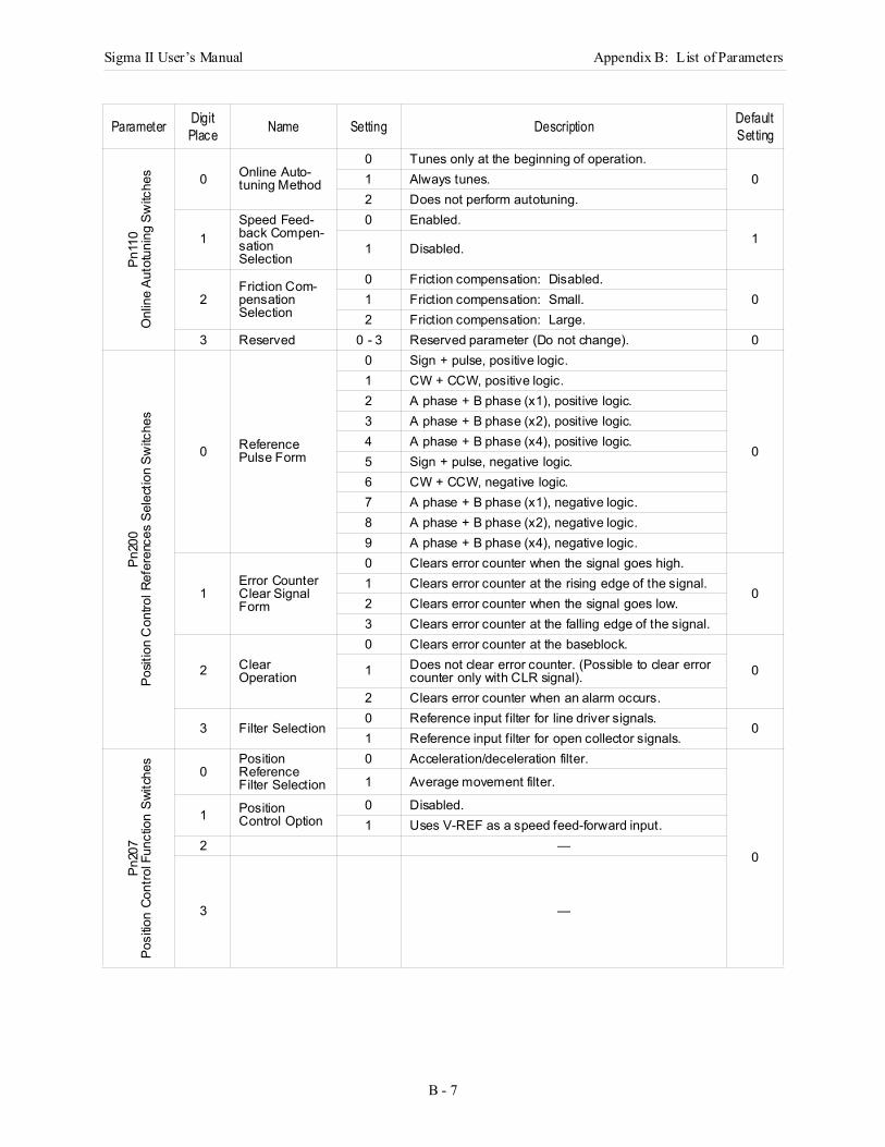
Sigma II User’s Manual Appendix B: List of Parameters
B - 7
Pn11
0 O
nlin
e Au
totu
ning
Sw
itche
s 0 Online Auto-tuning Method
0 Tunes only at the beginning of operation.01 Always tunes.
2 Does not perform autotuning.
1Speed Feed-back Compen-sation Selection
0 Enabled.1
1 Disabled.
2Friction Com-pensation Selection
0 Friction compensation: Disabled.01 Friction compensation: Small.
2 Friction compensation: Large.3 Reserved 0 - 3 Reserved parameter (Do not change). 0
Pn20
0Po
sitio
n C
ontro
l Ref
eren
ces
Sele
ctio
n Sw
itche
s
0 Reference Pulse Form
0 Sign + pulse, positive logic.
0
1 CW + CCW, positive logic.2 A phase + B phase (x1), positive logic.3 A phase + B phase (x2), positive logic.4 A phase + B phase (x4), positive logic.5 Sign + pulse, negative logic.6 CW + CCW, negative logic.7 A phase + B phase (x1), negative logic.8 A phase + B phase (x2), negative logic.9 A phase + B phase (x4), negative logic.
1Error Counter Clear Signal Form
0 Clears error counter when the signal goes high.
01 Clears error counter at the rising edge of the signal.2 Clears error counter when the signal goes low.3 Clears error counter at the falling edge of the signal.
2 Clear Operation
0 Clears error counter at the baseblock.
01 Does not clear error counter. (Possible to clear error counter only with CLR signal).
2 Clears error counter when an alarm occurs.
3 Filter Selection0 Reference input filter for line driver signals.
01 Reference input filter for open collector signals.
Pn20
7Po
sitio
n Co
ntro
l Fun
ctio
n Sw
itche
s
0Position Reference Filter Selection
0 Acceleration/deceleration filter.
0
1 Average movement filter.
1 Position Control Option
0 Disabled.1 Uses V-REF as a speed feed-forward input.
2 —
3 —
Parameter Digit Place Name Setting Description Default
Setting
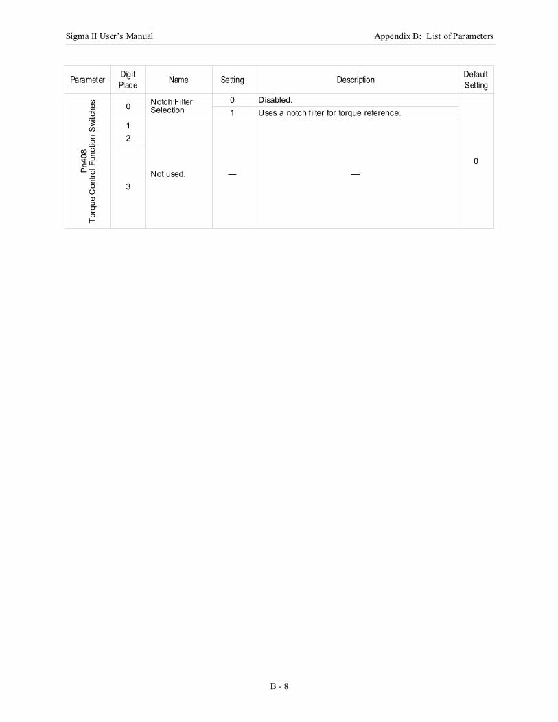
Sigma II User’s Manual Appendix B: List of Parameters
B - 8
Pn40
8To
rque
Con
trol F
unct
ion
Switc
hes 0 Notch Filter
Selection0 Disabled.
0
1 Uses a notch filter for torque reference.1
Not used. — —
2
3
Parameter Digit Place Name Setting Description Default
Setting
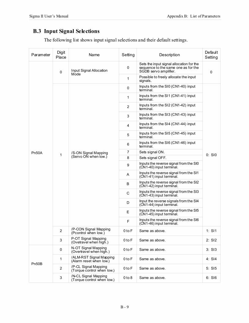
Sigma II User’s Manual Appendix B: List of Parameters
B - 9
B.3 Input Signal SelectionsThe following list shows input signal selections and their default settings.
Parameter Digit Place Name Setting Description Default
Setting
Pn50A
0 Input Signal Allocation Mode
0Sets the input signal allocation for the sequence to the same one as for the SGDB servo amplifier. 0
1 Possible to freely allocate the input signals.
1 /S-ON Signal Mapping (Servo ON when low.)
0 Inputs from the SI0 (CN1-40) input terminal.
0: SI0
1 Inputs from the SI1 (CN1-41) input terminal.
2 Inputs from the SI2 (CN1-42) input terminal.
3 Inputs from the SI3 (CN1-43) input terminal.
4 Inputs from the SI4 (CN1-44) input terminal.
5 Inputs from the SI5 (CN1-45) input terminal.
6 Inputs from the SI6 (CN1-46) input terminal.
7 Sets signal ON.8 Sets signal OFF.
9 Inputs the reverse signal from the SI0 (CN1-40) input terminal.
A Inputs the reverse signal from the SI1 (CN1-41) input terminal.
B Inputs the reverse signal from the SI2 (CN1-42) input terminal.
C Inputs the reverse signal from the SI3 (CN1-43) input terminal.
D Input the reverse signals from the SI4 (CN1-44) input terminal.
E Inputs the reverse signal from the SI5 (CN1-45) input terminal.
F Inputs the reverse signal from the SI6 (CN1-46) input terminal.
2 /P-CON Signal Mapping (Pcontrol when low.) 0 to F Same as above. 1: SI1
3 P-OT Signal Mapping (Ovetravel when high.) 0 to F Same as above. 2: SI2
Pn50B
0 N-OT Signal Mapping (Overtravel when high.) 0 to F Same as above. 3: SI3
1 /ALM-RST Signal Mapping (Alarm reset when low.) 0 to F Same as above. 4: SI4
2 /P-CL Signal Mapping (Torque control when low.) 0 to F Same as above. 5: SI5
3 /N-CL Signal Mapping (Torque control when low.) 0 to 8 Same as above. 6: SI6
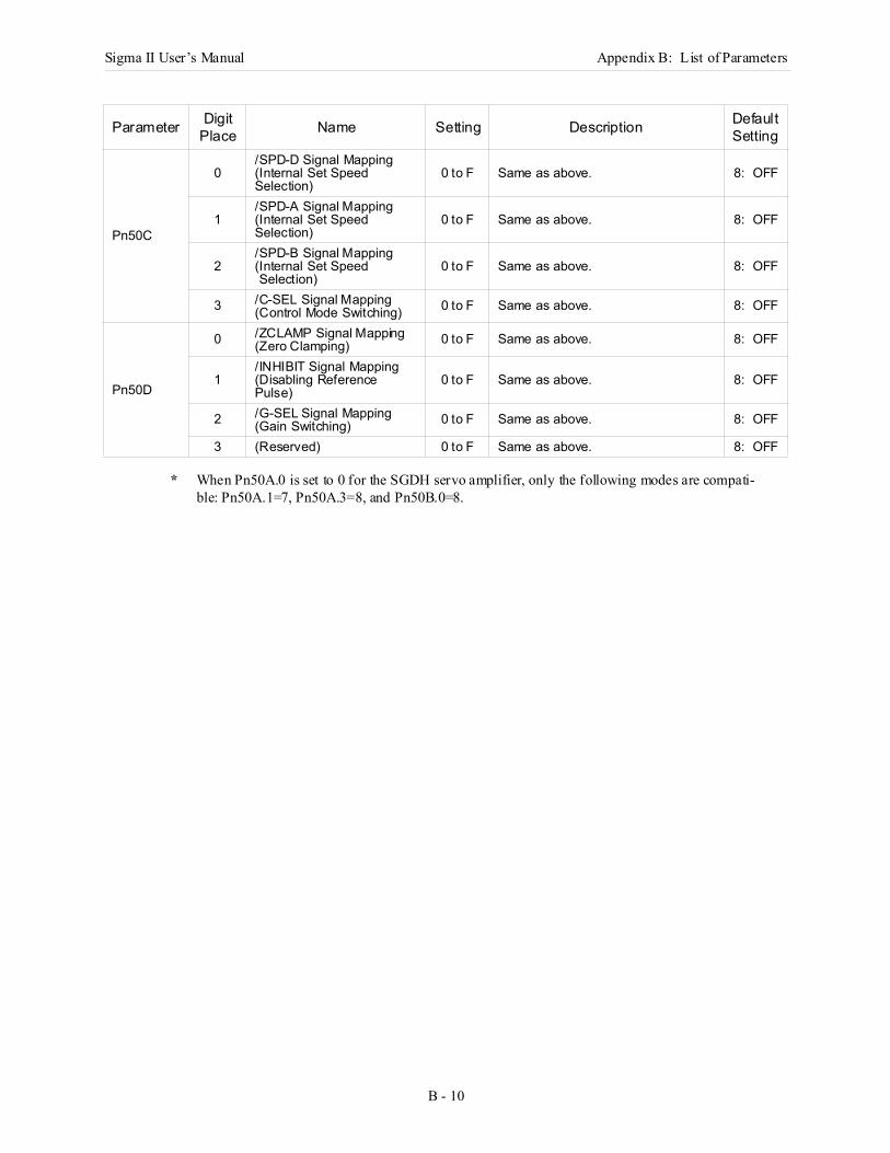
Sigma II User’s Manual Appendix B: List of Parameters
B - 10
* When Pn50A.0 is set to 0 for the SGDH servo amplifier, only the following modes are compati-ble: Pn50A.1=7, Pn50A.3=8, and Pn50B.0=8.
Pn50C
0/SPD-D Signal Mapping (Internal Set Speed Selection)
0 to F Same as above. 8: OFF
1/SPD-A Signal Mapping (Internal Set Speed Selection)
0 to F Same as above. 8: OFF
2/SPD-B Signal Mapping (Internal Set Speed Selection)
0 to F Same as above. 8: OFF
3 /C-SEL Signal Mapping (Control Mode Switching) 0 to F Same as above. 8: OFF
Pn50D
0 /ZCLAMP Signal Mapping (Zero Clamping) 0 to F Same as above. 8: OFF
1/INHIBIT Signal Mapping (Disabling Reference Pulse)
0 to F Same as above. 8: OFF
2 /G-SEL Signal Mapping (Gain Switching) 0 to F Same as above. 8: OFF
3 (Reserved) 0 to F Same as above. 8: OFF
Parameter Digit Place Name Setting Description Default
Setting
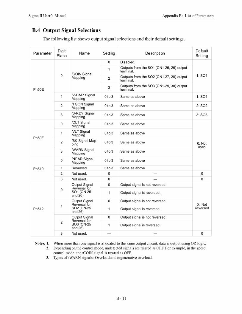
Sigma II User’s Manual Appendix B: List of Parameters
B - 11
B.4 Output Signal SelectionsThe following list shows output signal selections and their default settings.
Notes: 1. When more than one signal is allocated to the same output circuit, data is output using OR logic.2. Depending on the control mode, undetected signals are treated as OFF. For example, in the speed
control mode, the /COIN signal is treated as OFF.3. Types of /WARN signals: Overload and regenerative overload.
Parameter Digit Place Name Setting Description Default
Setting
Pn50E
0 /COIN Signal Mapping
0 Disabled.
1: SO1
1 Outputs from the SO1 (CN1-25, 26) output terminal.
2 Outputs from the SO2 (CN1-27, 28) output terminal.
3 Outputs from the SO3 (CN1-29, 30) output terminal.
1 /V-CMP Signal Mapping 0 to 3 Same as above 1: SO1
2 /TGON Signal Mapping 0 to 3 Same as above 2: SO2
3 /S-RDY Signal Mapping 0 to 3 Same as above 3: SO3
Pn50F
0 /CLT Signal Mapping 0 to 3 Same as above
0: Not used
1 /VLT Signal Mapping 0 to 3 Same as above
2 /BK Signal Map ping 0 to 3 Same as above
3 /WARN Signal Mapping 0 to 3 Same as above
Pn510
0 /NEAR Signal Mapping 0 to 3 Same as above
1 Reserved 0 to 3 Same as above2 Not used. 0 — 03 Not used. 0 — 0
Pn512
0Output Signal Reversal for SO1 (CN-25 and 26)
0 Output signal is not reversed.
0: Not reversed
1 Output signal is reversed.
1Output Signal Reversal for SO2 (CN-25 and 26)
0 Output signal is not reversed.
1 Output signal is reversed.
2Output Signal Reversal for SO3 (CN-25 and 26)
0 Output signal is not reversed.
1 Output signal is reversed.
3 Not used. — — 0

Sigma II User’s Manual Appendix B: List of Parameters
B - 12
B.5 Auxiliary FunctionsThe following list shows the available auxiliary functions.
Parameter FunctionFn000 Alarm traceback data display.Fn001 Rigidity setting for online autotuning.Fn002 JOG mode operation.Fn003 Zero-point search mode.Fn004 (Reserved parameter).Fn005 Parameter settings initialization.Fn006 Alarm traceback data clear.Fn007 Writing to EEPROM inertia ratio data obtained from online autotuning.Fn008 Absolute encoder multi-turn reset and encoder alarm reset.Fn009 Automatic tuning of analog (speed, torque) reference offset.Fn00A Manual adjustment of speed reference offset.Fn00B Manual adjustment of torque reference offset.Fn00C Manual zero-adjustment of analog monitor output.Fn00D Manual adjustment of analog monitor output gain.Fn00E Automatic adjustment of motor current detection signal offset.Fn00F Manual adjustment of motor current detection signal offset.Fn010 Write protect setting (protects parameters from being changed).Fn011 Motor model display.Fn012 Software version display.Fn013 Multi-Turn Limit Setting: Change when a Multi-Turn Limit Disagreement Alarm (A.CC) occurs.Fn014 Clear Option Unit Detection Alarm (A.E7).
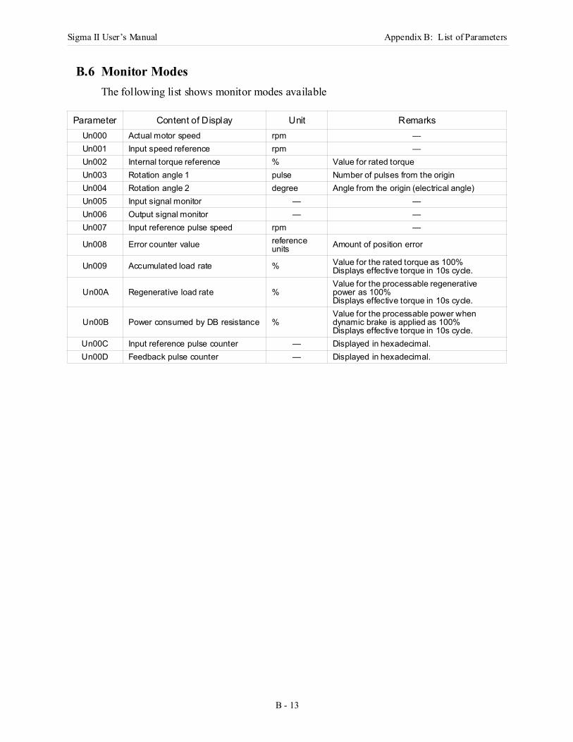
Sigma II User’s Manual Appendix B: List of Parameters
B - 13
B.6 Monitor ModesThe following list shows monitor modes available
Parameter Content of Display Unit RemarksUn000 Actual motor speed rpm —Un001 Input speed reference rpm —Un002 Internal torque reference % Value for rated torqueUn003 Rotation angle 1 pulse Number of pulses from the originUn004 Rotation angle 2 degree Angle from the origin (electrical angle)Un005 Input signal monitor — —Un006 Output signal monitor — —Un007 Input reference pulse speed rpm —
Un008 Error counter value reference units Amount of position error
Un009 Accumulated load rate % Value for the rated torque as 100%Displays effective torque in 10s cycle.
Un00A Regenerative load rate %Value for the processable regenerative power as 100%Displays effective torque in 10s cycle.
Un00B Power consumed by DB resistance %Value for the processable power when dynamic brake is applied as 100%Displays effective torque in 10s cycle.
Un00C Input reference pulse counter — Displayed in hexadecimal.Un00D Feedback pulse counter — Displayed in hexadecimal.

Sigma II User’s Manual Appendix B: List of Parameters
B - 14
Notes:
Sigma II User’s Manual Appendix C: Examples of Standard Connections
C - 1
C Examples of Standard ConnectionsThe following diagrams show examples of standard servo amplifier connections by specifications and type of control.
C.1 Single-Phase Power Supply Specifications .........................................................C-2
C.2 Three-Phase Power Supply Specifications (200V)..............................................C-3
C.3 Three-Phase Power Supply Specifications (400V)..............................................C-4
Large Capacity Power Supply Specifications (400V) .........................................C-5
C.4 Position Control Mode .........................................................................................C-7
C.5 Speed Control Mode ............................................................................................C-8
C.6 Torque Control Mode...........................................................................................C-9
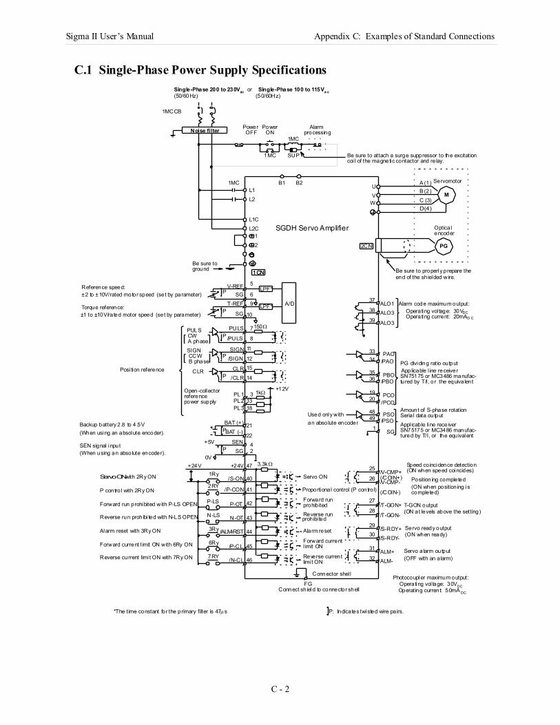
Sigma II User’s Manual Appendix C: Examples of Standard Connections
C - 2
C.1 Single-Phase Power Supply Specifications
Photocoupler maximum output:Operating vol tage: 30VDCOperating current: 50mA DC
3.3kΩ
1kΩ
Reference speed:±2 to ±10V/rated motor speed (set by parameter) Torque reference:±1 to ±10V/rated motor speed (set by parameter)
Alarm code maximum output:Operating vol tage: 30VDC
Backup battery 2.8 to 4 .5V(When using an absolute encoder).
SEN signal input(When using an absolute encoder).
Operating current: 20mAD C
P: Indicates twisted wire pa irs.*The time constant for the primary filter is 47µs
LPF*
1CN
PG
M
Noise filter
SGDH Servo Amplifier
Single-Phase 200 to 230Vac or Single-Phase 100 to 115Va c(50/60Hz) (50/60Hz)
1MCCB
Power Power
1MC
1MC
1MC
SUP
Alarm
Be sure to attach a surge suppressor to the excitation
B1 B2L1L2
UV
L1CL2C
W
12
1CN
2CN
V-REFP SG
9
10
A/D
PULS/PULS
PULS
P
SIGN
CLR
7
/SIGNP
P
/CLR
PL1PL2
8
11
1215
14
31318
150Ω
PL3
+12V
38
39
3334
3536
1920
49
121
48
37
BAT (+)P
SENSG
2242
47
40
41
42
43
44
45
25
26
27
28
2930
31
1Ry
2RY
P-LS
N-LS
3Ry
6Ry
7RY 46
P
BAT (-)
+24V
+5V
0V+24V
Used only withan absolute encoder
Servo ON
Proportional control (P contro l)
Forward run
Reverse run
Alarm reset
Forward current
/S-ON
/P-CON
P-OT
N-OT
/ALM-RST
/P-CL
/N-CL
/V-CMP+
/T-GON+
/S-RDY+/S-RDY-
/T-GON-
/V-CMP-
Reverse current
prohib ited
prohibi ted
l imit ON
limi t ON
ALO1ALO3
ALO3
PAO/PAO
PBO/PBO
PCO/PCO
PSO/PSO
SG
Amount of S-phase rotation
PG dividing ratio output
Be sure to properly prepare the
Optica l
coi l of the magnetic contactor and re lay.
end of the sh ielded wire.
Servomotor
encoder
Applicable l ine receiverSN75175 or MC3486 manufac-tured by T/I, or the equiva lent
Seria l data outputAppl icable line receiverSN75175 or MC3486 manufac-tured by T/I, or the equivalent
Position ing completed(ON when position ing iscompleted)
T-GON output
Servo ready output
Servo a larm output
(ON at levels above the setting)
(ON when ready)
(OFF with an a larm)
Connect sh ield to connector shell
Connector shel l
Forward run prohibited with P-LS OPEN
Reverse run prohibi ted with N-LS OPEN
Alarm reset with 3Ry ON
P contro l with 2Ry ON
Reverse current limi t ON with 7Ry ON
Forward current l imit ON with 6Ry ON
Servo ON with 2Ry ON
Posi tion reference
Open-collector
SIGN
CW
CCW
CLR
B phase
referencepower supply
A phase
A (1)B (2)C (3)D (4)
Be sure toground
OFF ON processing
ALM+ALM-
FG
32
T-REF LPF*SG
5
6
P
(/COIN+)
(/COIN-)
Speed co incidence detection(ON when speed coincides)
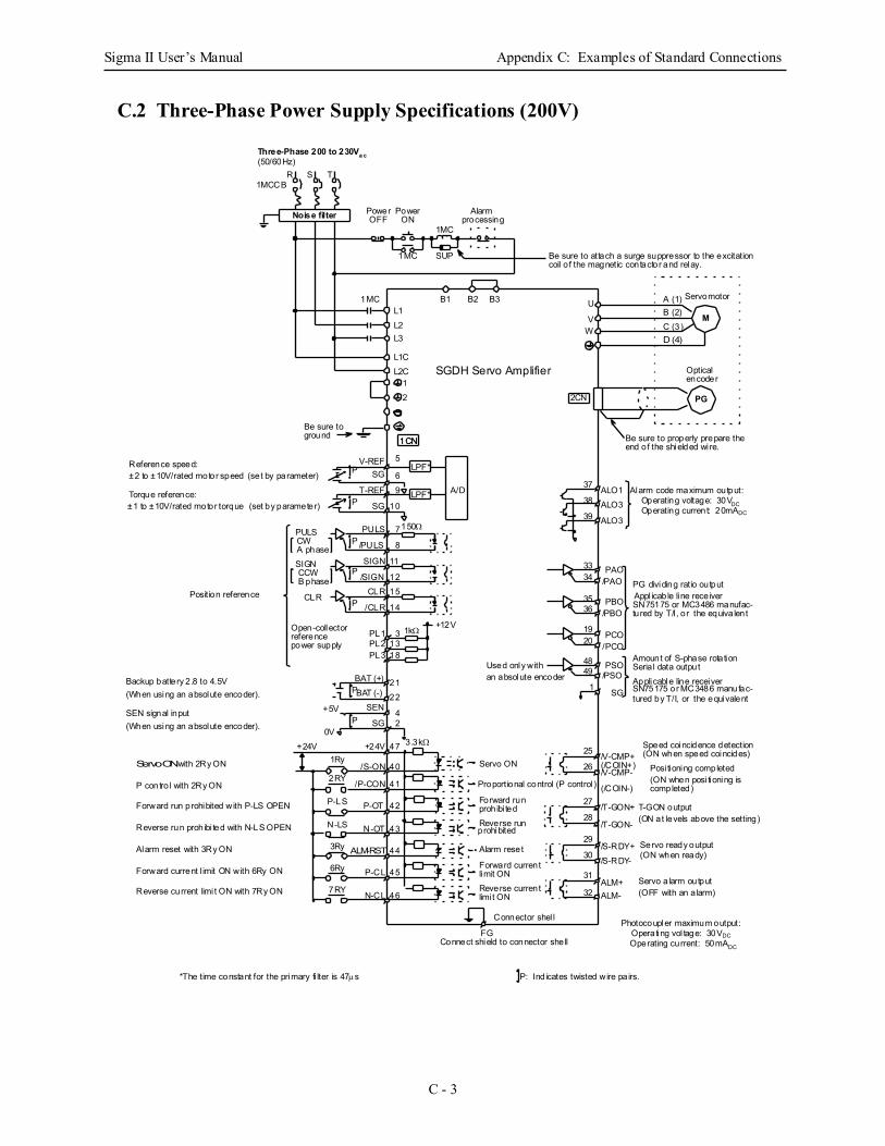
Sigma II User’s Manual Appendix C: Examples of Standard Connections
C - 3
C.2 Three-Phase Power Supply Specifications (200V)
Photocoupler maximum output:Operating vol tage: 30VDCOperating current: 50mADC
1kΩ
Reference speed:±2 to ±10V/rated motor speed (set by parameter) Torque reference:±1 to ±10V/rated motor torque (set by parameter)
Alarm code maximum output:Operating voltage: 30VDC
Backup battery 2.8 to 4.5V(When using an absolute encoder).
SEN signal input(When using an absolute encoder).
Operating current: 20mADC
P: Ind icates twisted wire pa irs.*The time constant for the primary fi lter is 47µs
LPF*
1CN
PG
M
Noise filter
SGDH Servo Amplifier
Three-Phase 200 to 230Va c(50/60Hz)
R S T1MCCB
Power Power
1MC
1MC
1MC
SUP
Alarm
Be sure to attach a surge suppressor to the excitation
B1 B2 B3L1L2
U
V
L1CL2C
L3W
12
1CN
2CN
V-REFP SG
9
10
A/D
PULS/PULS
PULS
P
SIGN
CLR
7
/SIGNP
P
/CLR
PL1PL2
8
11
1215
14
31318
150Ω
PL3
+12V
38
39
3334
3536
1920
49
121
48
37
BAT (+)P
SEN
SG
22
42
47
40
41
42
43
44
45
25
26
27
28
29
30
31
1Ry
2RY
P-LS
N-LS
3Ry
6Ry
7RY 46
P
BAT (-)
+24V
+5V
0V+24V
Used only withan absolute encoder
Servo ON
Proportional control (P control )
Forward run
Reverse run
Alarm reset
Forward current
/S-ON
/P-CON
P-OT
N-OT
ALM-RST
P-CL
N-CL
/V-CMP+
/T-GON+
/S-RDY+/S-RDY-
/T-GON-
/V-CMP-
Reverse current
prohibi ted
prohibited
limit ON
limi t ON
ALO1ALO3
ALO3
PAO/PAO
PBO/PBO
PCO/PCO
PSO/PSO
SG
Amount of S-phase rotation
PG dividing ratio output
Optical
coil o f the magnetic contactor and relay.
Servomotor
encoder
Appl icable line receiverSN75175 or MC3486 manufac-tured by T/I, or the equiva lent
Seria l data outputApplicable line receiverSN75175 or MC3486 manufac-tured by T/I, or the equivalent
Posi tioning completed(ON when posi tioning iscompleted)
T-GON output
Servo ready output
Servo a larm output
(ON at levels above the setting)
(ON when ready)
(OFF with an a larm)
Connect shield to connector shell
Connector shel l
Forward run prohibited with P-LS OPEN
Reverse run prohibi ted with N-LS OPEN
Alarm reset with 3Ry ON
P contro l with 2Ry ON
Reverse current limi t ON with 7Ry ON
Forward current l imit ON with 6Ry ON
Servo ON with 2Ry ON
Position reference
Open-collector
SIGN
CW
CCW
CLR
B phase
referencepower supply
A phase
A (1)B (2)C (3)D (4)
Be sure toground
OFF ON processing
ALM+ALM-
3.3kΩ
FG
32
T-REF LPF*SG
5
6
P
(/COIN+)
(/COIN-)
Speed coincidence detection(ON when speed coincides)
Be sure to properly prepare theend of the shielded wi re.
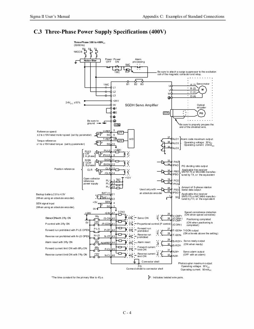
Sigma II User’s Manual Appendix C: Examples of Standard Connections
C - 4
C.3 Three-Phase Power Supply Specifications (400V)
Photocoupler maximum output:Operating vol tage: 30VDCOperating current: 50mADC
1kΩ
Reference speed:±2 to ±10V/rated motor speed (set by parameter) Torque reference:±1 to ±10V/rated torque (set by parameter)
Alarm code maximum output:Operating voltage: 30VDC
Backup battery 2.8 to 4.5V(When using an absolute encoder).
SEN signal input(When using an absolute encoder).
Operating current: 20mADC
P: Ind icates twisted wire pa irs.*The time constant for the primary fi lter is 47µs
LPF*
1CN
PG
M
Noise filter
SGDH Servo Amplifier
Three-Phase 380 to 480Va c(50/60Hz)
R S T1MCCB
Power Power
1MC
1MC
1MC
SUP
Alarm
Be sure to attach a surge suppressor to the excitation
B1 B2 B3L1L2
U
V
+24V0V
L3 W
12
1CN
2CN
V-REFP SG
9
10
A/D
PULS/PULS
PULS
P
SIGN
CLR
7
/SIGNP
P
/CLR
PL1PL2
8
11
1215
14
31318
150Ω
PL3
+12V
38
39
3334
3536
1920
49
121
48
37
BAT (+)P
SEN
SG
2242
47
40
41
42
43
44
45
25
26
27
28
29
30
31
1Ry
2RY
P-LS
N-LS
3Ry
6Ry
7RY 46
P
BAT (-)
+24V
+5V
0V+24V
Used only withan absolute encoder
Servo ON
Proportional control (P control )
Forward run
Reverse run
Alarm reset
Forward current
/S-ON
/P-CON
P-OT
N-OT
ALM-RST
P-CL
N-CL
/V-CMP+
/T-GON+
/S-RDY+/S-RDY-
/T-GON-
/V-CMP-
Reverse current
prohibi ted
prohibited
limit ON
limi t ON
ALO1ALO3
ALO3
PAO/PAO
PBO/PBO
PCO/PCO
PSO/PSO
SG
Amount of S-phase rotation
PG dividing ratio output
Be sure to properly prepare the
Optical
coil o f the magnetic contactor and relay.
end of the shielded wi re.
Servomotor
encoder
Appl icable line receiverSN75175 or MC3486 manufac-tured by T/I, or the equiva lent
Seria l data outputApplicable line receiverSN75175 or MC3486 manufac-tured by T/I, or the equivalent
Posi tioning completed(ON when posi tioning iscompleted)
T-GON output
Servo ready output
Servo a larm output
(ON at levels above the setting)
(ON when ready)
(OFF with an a larm)
Connect shield to connector shell
Connector shel l
Forward run prohibi ted with P-LS OPEN
Reverse run prohib ited wi th N-LS OPEN
Alarm reset wi th 3Ry ON
P control wi th 2Ry ON
Reverse current limit ON wi th 7Ry ON
Forward current limi t ON with 6Ry ON
Servo ON with 2Ry ON
Position reference
Open-collector
SIGN
CW
CCW
CLR
B phase
referencepower supply
A phase
A (1)B (2)C (3)D (4)
Be sure toground
OFF ON processing
ALM+ALM-
3.3kΩ
FG
32
T-REF LPF*SG
5
6
P
(/COIN+)
(/COIN-)
Speed coincidence detection(ON when speed coincides)
24VD C ±15%
0V
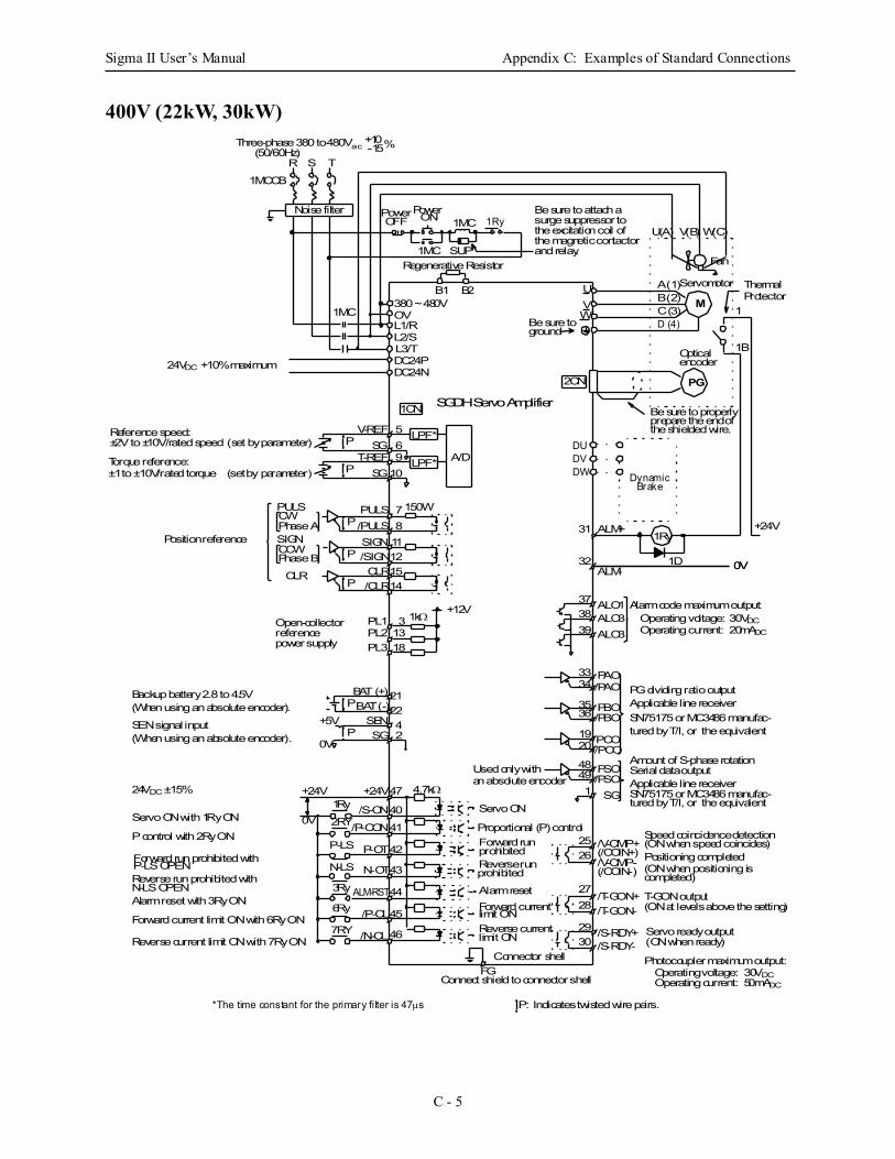
Sigma II User’s Manual Appendix C: Examples of Standard Connections
C - 5
400V (22kW, 30kW)
Servomotor
Fan
U(A) V(B) W(C)
P LPF*
P LPF*
Photocoupler maximum output:Operating voltage: 30VDCOperating current: 50mADC
Reference speed:±2V to ±10V/rated speed (set by parameter)
Torque reference:±1 to ±10V/rated torque (set by parameter)
Alarm code maximum output:Operating voltage: 30VDC
Backup battery 2.8 to 4.5V(When using an absolute encoder).
SEN signal input(When using an absolute encoder).
Operating current: 20mADC
P: Indicates twisted wire pairs.
1CN
PG
M
Noise filter
SGDH Servo Amplifier
Three-phase 380 to 480Vac(50/60Hz)
R S T
1MCCB
PowerPower1MC
1MC
1MC
SUP
Be sure to attach a
B1 B2
L1/RL2/S
UV
DC24PDC24N
L3/T
W
V-REF
910
A/D
PULS
/PULSPULS
P
SIGN
CLR
7
/SIGNP
P
/CLR
811121514
150W
3839
3334
3536
1920
491
48
37
BAT (+)P
SENSG
47
40
41
42
43
44
45
2526
2728
2930
31
46
P
BAT (-)
+24V
+5V
0V
+24V
Used only withan absolute encoder
Servo ON
Proportional (P) controlForward run
Reverse run
Alarm resetForward current
/S-ON
/P-CON
P-OT
N-OT
ALM-RST
/P-CL
/N-CL
/V-CMP+
/T-GON+
/S-RDY+/S-RDY-
/T-GON-
/V-CMP-
Reverse current
prohibited
prohibited
limit ON
limit ON
ALO1ALO3ALO3
PAO/PAO
PBO/PBO
PCO/PCO
PSO/PSO
SG
Amount of S-phase rotation
PG dividing ratio output
Be sure to properly
Optical
prepare the end of
encoder
Applicable line receiverSN75175 or MC3486 manufac-tured by T/I, or the equivalent
Serial data outputApplicable line receiverSN75175 or MC3486 manufac-tured by T/I, or the equivalent
Positioning completed(ON when positioning iscompleted)
T-GON output
Servo ready output
(ON at levels above the setting)
(ON when ready)
Connect shield to connector shell
Connector shell
Forward run prohibited with
Reverse run prohibited with
Alarm reset with 3Ry ON
P control with 2Ry ON
Reverse current limit ON with 7Ry ON
Forward current limit ON with 6Ry ON
N-LS OPEN
P-LS OPEN
Servo ON with 1Ry ON
Position reference
CW
CLR
Phase A
A (1)B (2)C (3)D (4)Be sure to
ground
OFF ON 1Ry
ALM+
FG
56
(/COIN+)
(/COIN-)
Speed coincidence detection(ON when speed coincides)
24VDC ±15%
Regenerative Resistor
SGT-REF
SG
1Ry
2RY
P-LS
N-LS
3Ry
6Ry
7RY
4.7kΩ
the shielded wire.
1
1B
+24V1Ry
1D 0VALM-32
0V
+10-15%
24VDC +10% maximum
DU
DWDV
DynamicBrake
*The time constant for the primary filter is 47µs
2CN
SIGNCCWPhase B
surge suppressor to the excitation coil of the magnetic contactor and relay.
0V
1kΩPL1PL2
31318PL3
+12VOpen-collectorreferencepower supply
212242
ThermalProtector
OV380 ~ 480V
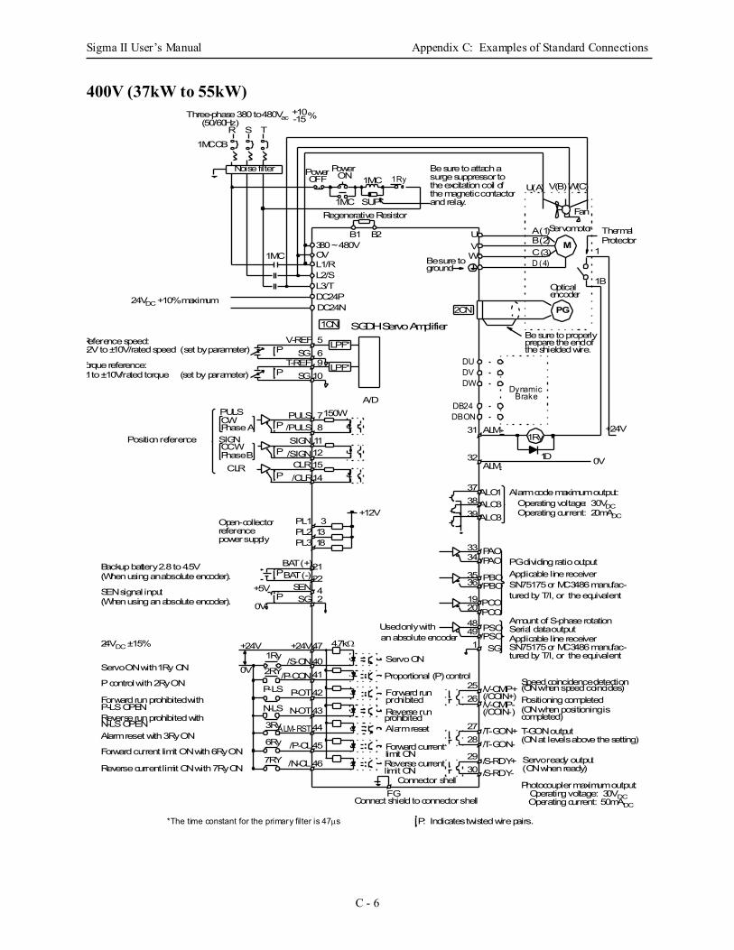
Sigma II User’s Manual Appendix C: Examples of Standard Connections
C - 6
400V (37kW to 55kW)
Photocoupler maximum output:Operating voltage: 30VDCOperating current: 50mADC
Reference speed:±2V to ±10V/rated speed (set by parameter)
Torque reference:±1 to ±10V/rated torque (set by parameter)
Alarm code maximum output:Operating voltage: 30VDCOperating current: 20mADC
P: Indicates twisted wire pairs.
1CN
PG
M
Noise filter
SGDH Servo Amplifier
Three-phase 380 to 480Vac(50/60Hz)
R S T
1MCCB
Power Power1MC
1MC
1MC
SUP
Be sure to attach a
B1 B2
L1/RL2/S
UV
DC24PDC24N
L3/T
W
PULS
/PULSPULS
P
SIGN
CLR
7
/SIGNP
P
/CLR
811121514
150W
3839
3334
3536
1920
491
48
37
2526
2728
2930
31
Used only withan absolute encoder
Servo ON
Proportional (P) control
Forward run
Reverse run
Alarm reset
Forward current
/V-CMP+
/T-GON+
/S-RDY+/S-RDY-
/T-GON-
/V-CMP-
Reverse current
prohibited
prohibited
limit ON
limit ON
ALO1ALO3ALO3
PAO/PAO
PBO/PBO
PCO/PCO
PSO/PSO
SG
Amount of S-phase rotation
PG dividing ratio output
Be sure to properly
Optical
prepare the end of
Servomotor
encoder
Applicable line receiverSN75175 or MC3486 manufac-tured by T/I, or the equivalent
Serial data outputApplicable line receiverSN75175 or MC3486 manufac-tured by T/I, or the equivalent
Positioning completed(ON when positioning iscompleted)
T-GON output
Servo ready output
(ON at levels above the setting)
(ON when ready)
Connect shield to connector shell
Connector shell
Position reference
CW
CLR
Phase A
A (1)B (2)C (3)D (4)Be sure to
ground
OFF ON 1Ry
ALM+
FG
(/COIN+)
(/COIN-)
Speed coincidence detection(ON when speed coincides)
Fan
U(A) V(B)W(C)
Regenerative Resistor
the shielded wire.
1
1B
+24V1Ry
1D 0VALM-32
0V
+10-15%
DU
DWDV
DBONDB24
DynamicBrake
*The time constant for the primary filter is 47µs
2CN
SIGNCCWPhase B
surge suppressor to the excitation coil of the magnetic contactor and relay.
P LPF*
P LPF*
V-REF
910
56SG
T-REFSG
A/D
24VDC +10% maximum
PL1PL2
31318PL3
+12VOpen-collectorreferencepower supply
Backup battery 2.8 to 4.5V(When using an absolute encoder).
SEN signal input(When using an absolute encoder).
21BAT (+)P
SENSG
2242
47
4041
42
43
44
45
46
P
BAT (-)
+24V
+5V
0V
+24V
/S-ON
/P-CON
P-OT
N-OT
ALM-RST
/P-CL
/N-CL
Forward run prohibited with
Reverse run prohibited with
Alarm reset with 3Ry ON
P control with 2Ry ON
Reverse current limit ON with 7Ry ON
Forward current limit ON with 6Ry ON
N-LS OPEN
P-LS OPEN
Servo ON with 1Ry ON
24VDC ±15%1Ry
2RY
P-LS
N-LS
3Ry
6Ry
7RY
4.7kΩ
380 ~ 480VOV
ThermalProtector
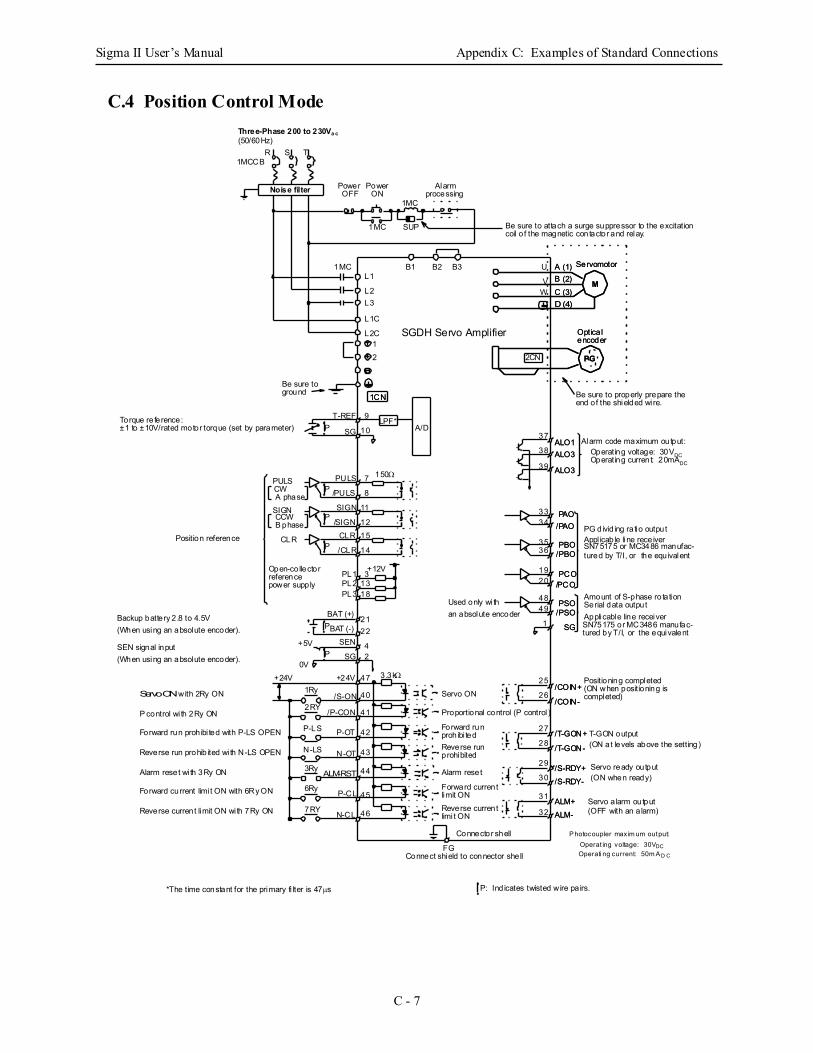
Sigma II User’s Manual Appendix C: Examples of Standard Connections
C - 7
C.4 Position Control Mode
Alarm code maximum output:Operating voltage: 30VDC
Photocoupler maxim um output:Operat ing voltage: 30VDCOperati ng current: 50m A D C
Backup battery 2.8 to 4.5V(When using an absolute encoder).
SEN signal input(When using an absolute encoder).
Operating current: 20mADC
P: Ind icates twisted wire pa irs.*The time constant for the primary fi lter is 47µs
Torque reference:±1 to ±10V/rated motor torque (set by parameter)
LPF*
1CN
PG
M
Noise filter
SGDH Servo Amplifier
Three-Phase 200 to 230Va c(50/60Hz)
R S T1MCCB
Power Power
1MC
1MC
1MC
SUP
Alarm
Be sure to attach a surge suppressor to the excitation
B1 B2 B3L1
L2
U
V
L1C
L2C
L3W
12
1CN
2CN
T-REFP SG
9
10 A/D
PULS/PULS
PULS
P
SIGN
CLR
7
/SIGNP
P
/CLR
PL1PL2
8
11
1215
14
31318
150Ω
PL3
+12V
38
39
3334
3536
1920
49
121
48
37
BAT (+)P
SEN
SG
22
42
47
40
41
42
43
44
45
25
26
27
28
29
30
31
1Ry
2RY
P-LS
N-LS
3Ry
6Ry
7RY 46
P
BAT (-)
+24V
+5V
0V+24V
Used only wi than absolute encoder
Servo ON
Proportional control (P control )
Forward run
Reverse run
Alarm reset
Forward current
/S-ON
/P-CON
P-OT
N-OT
ALM-RST
P-CL
N-CL
/COIN+
/T-GON+
/S-RDY+/S-RDY-
/T-GON-
/COIN-
Reverse current
prohibi ted
prohibited
limit ON
limi t ON
ALO1ALO3
ALO3
PAO/PAO
PBO/PBO
PCO/PCO
PSO/PSO
SG
Amount of S-phase rotation
PG divid ing ra tio output
Optica l
coil o f the magnetic contactor and relay.
Servomotor
encoder
Appl icable line receiverSN75175 or MC3486 manufac-tured by T/I, or the equivalent
Serial data outputApplicable line receiverSN75175 or MC3486 manufac-tured by T/I, or the equivalent
Positioning completed(ON when positioning iscompleted)
T-GON output
Servo ready output
Servo a larm output
(ON at levels above the setting)
(ON when ready)
(OFF with an a larm)
Connect shield to connector shell
Connector shell
Forward run prohibi ted with P-LS OPEN
Reverse run prohib ited wi th N-LS OPEN
Alarm reset wi th 3Ry ON
P control wi th 2Ry ON
Reverse current limit ON wi th 7Ry ON
Forward current limi t ON with 6Ry ON
Servo ON with 2Ry ON
Position reference
Open-collector
SIGN
CW
CCW
CLR
B phase
referencepower supply
A phase
A (1)B (2)C (3)D (4)
Be sure toground
OFF ON processing
ALM+ALM-
3.3kΩ
FG
32
Be sure to properly prepare theend of the shielded wi re.
PG
M
/COIN+
/T-GON+
/S-RDY+/S-RDY-
/T-GON-
/COIN-
ALO1ALO3
ALO3
PAO/PAO
PBO/PBO
PCO/PCO
PSO/PSO
SG
Optica l
Servomotor
encoder
A (1)B (2)C (3)D (4)
ALM+ALM-
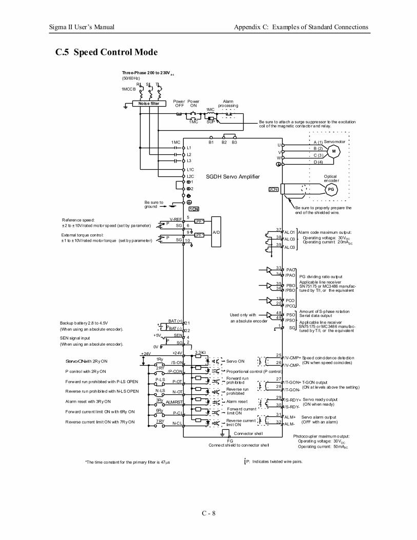
Sigma II User’s Manual Appendix C: Examples of Standard Connections
C - 8
C.5 Speed Control Mode
Photocoupler maximum output:Operating voltage: 30VDCOperating current: 50mADC
Reference speed:±2 to ±10V/rated motor speed (set by parameter) External torque contro l:±1 to ±10V/rated motor torque (set by parameter)
Alarm code maximum output:Operating voltage: 30VDC
Backup battery 2.8 to 4.5V(When using an absolute encoder).
SEN signal input(When using an absolute encoder).
Operating current: 20mADC
P: Ind icates twisted wire pa irs.*The time constant for the primary fi lter is 47µs
LPF*
1CN
PG
M
Noise filter
SGDH Servo Amplifier
Three-Phase 200 to 230V a c(50/60Hz)
R S T1MCCB
Power Power
1MC
1MC
1MC
SUP
Alarm
Be sure to attach a surge suppressor to the excitation
B1 B2 B3L1L2
U
V
L1CL2C
L3 W
12
1CN
2CN
V-REFP SG
9
10
A/D38
39
3334
3536
1920
49
121
48
37
BAT (+)P
SEN
SG
2242
25
26
27
28
29
30
31
1Ry
2RY
P-LS
N-LS
3Ry
6Ry
7RY
P
BAT (-)
+24V
+5V
0V+24V
Used only wi than absolute encoder
Servo ON
Proportional control (P control )Forward run
Reverse run
Alarm reset
Forward current
/S-ON
/P-CON
P-OT
N-OT
ALM-RST
P-CL
N-CL
/V-CMP+
/T-GON+
/S-RDY+/S-RDY-
/T-GON-
/V-CMP-
Reverse current
prohibi ted
prohibited
limit ON
limi t ON
ALO1ALO3
ALO3
PAO/PAO
PBO/PBO
PCO/PCO
PSO/PSO
SG
Amount of S-phase rotation
PG dividing ratio output
Be sure to properly prepare the
Optical
coil o f the magnetic contactor and relay.
end of the shielded wi re.
Servomotor
encoder
Appl icable line receiverSN75175 or MC3486 manufac-tured by T/I, or the equivalent
Serial data outputApplicable line receiverSN75175 or MC3486 manufac-tured by T/I, or the equivalent
T-GON output
Servo ready output
Servo a larm output
(ON at levels above the setting)
(ON when ready)
(OFF with an a larm)
Connect shield to connector shell
Connector shel l
Forward run prohibited with P-LS OPEN
Reverse run prohibi ted with N-LS OPEN
Alarm reset with 3Ry ON
P contro l with 2Ry ON
Reverse current limi t ON with 7Ry ON
Forward current l imit ON with 6Ry ON
Servo ON with 2Ry ON
A (1)B (2)C (3)D (4)
Be sure toground
OFF ON processing
ALM+ALM-
3.3kΩ
FG
32
LPF*SG
5
6
P
Speed coincidence detection(ON when speed co incides)
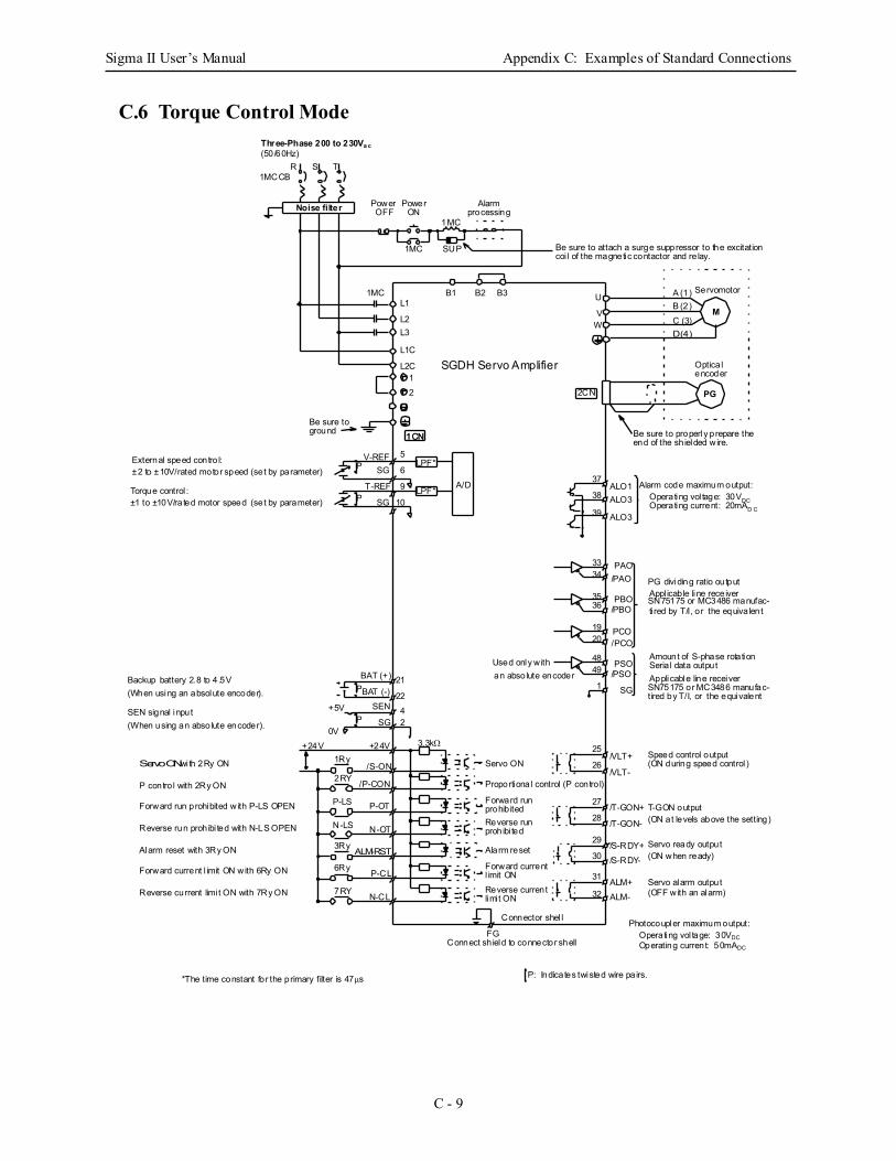
Sigma II User’s Manual Appendix C: Examples of Standard Connections
C - 9
C.6 Torque Control Mode
Photocoupler maximum output:Operating vol tage: 30VDCOperating current: 50mADC
External speed contro l:±2 to ±10V/rated motor speed (set by parameter) Torque control :±1 to ±10V/rated motor speed (set by parameter)
Alarm code maximum output:Operating vol tage: 30VDC
Backup battery 2.8 to 4 .5V(When using an absolute encoder).
SEN signal input(When using an absolute encoder).
Operating current: 20mAD C
P: Indicates twisted wire pa irs.*The time constant for the primary filter is 47µs
LPF*
1CN
PG
M
Noise filter
SGDH Servo Amplifier
Three-Phase 200 to 230Va c(50/60Hz)
R S T1MCCB
Power Power
1MC
1MC
1MC
SUP
Alarm
Be sure to attach a surge suppressor to the excitation
B1 B2 B3L1
L2
U
V
L1C
L2C
L3W
12
1CN
2CN
V-REFP SG
9
10
A/D38
39
3334
3536
1920
49
121
48
37
BAT (+)P
SEN
SG
2242
25
26
27
28
29
30
31
1Ry
2RY
P-LS
N-LS
3Ry
6Ry
7RY
P
BAT (-)
+24V
+5V
0V+24V
Used only withan absolute encoder
Servo ON
Proportional control (P contro l)
Forward run
Reverse run
Alarm reset
Forward current
/S-ON
/P-CON
P-OT
N-OT
ALM-RST
P-CL
N-CL
/VLT+
/T-GON+
/S-RDY+/S-RDY-
/T-GON-
/VLT-
Reverse current
prohib ited
prohibi ted
l imit ON
limi t ON
ALO1ALO3
ALO3
PAO/PAO
PBO/PBO
PCO/PCO
PSO/PSO
SG
Amount of S-phase rotation
PG dividing ratio output
Be sure to properly prepare the
Optica l
coi l of the magnetic contactor and re lay.
end of the sh ielded wire.
Servomotor
encoder
Appl icable line receiverSN75175 or MC3486 manufac-ti red by T/I, or the equiva lent
Seria l data outputApplicable line receiverSN75175 or MC3486 manufac-tired by T/I, or the equivalent
T-GON output
Servo ready output
Servo alarm output
(ON at levels above the setting)
(ON when ready)
(OFF with an alarm)
Connect sh ield to connector shell
Connector shel l
Forward run prohibited with P-LS OPEN
Reverse run prohibi ted with N-LS OPEN
Alarm reset with 3Ry ON
P contro l with 2Ry ON
Reverse current limi t ON with 7Ry ON
Forward current l imit ON with 6Ry ON
Servo ON with 2Ry ON
A (1)B (2)C (3)D (4)
Be sure toground
OFF ON processing
ALM+ALM-
3.3kΩ
FG
32
T-REF LPF*SG
5
6
P
Speed control output(ON during speed control )

Sigma II User’s Manual Appendix C: Examples of Standard Connections
C - 10
Notes:
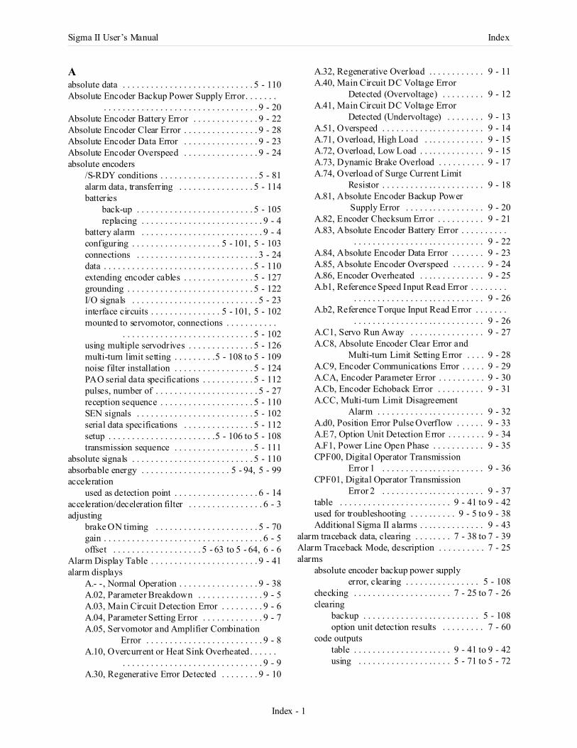
Sigma II User’s Manual Index
Index - 1
Aabsolute data . . . . . . . . . . . . . . . . . . . . . . . . . . . . 5 - 110Absolute Encoder Backup Power Supply Error. . . . . . .
. . . . . . . . . . . . . . . . . . . . . . . . . . . . . . . . . 9 - 20Absolute Encoder Battery Error . . . . . . . . . . . . . . 9 - 22Absolute Encoder Clear Error . . . . . . . . . . . . . . . . 9 - 28Absolute Encoder Data Error . . . . . . . . . . . . . . . . 9 - 23Absolute Encoder Overspeed . . . . . . . . . . . . . . . . 9 - 24absolute encoders
/S-RDY conditions . . . . . . . . . . . . . . . . . . . . . 5 - 81alarm data, transferring . . . . . . . . . . . . . . . . 5 - 114batteries
back-up . . . . . . . . . . . . . . . . . . . . . . . . . 5 - 105replacing . . . . . . . . . . . . . . . . . . . . . . . . . . 9 - 4
battery alarm . . . . . . . . . . . . . . . . . . . . . . . . . . 9 - 4configuring . . . . . . . . . . . . . . . . . . . 5 - 101, 5 - 103connections . . . . . . . . . . . . . . . . . . . . . . . . . . 3 - 24data . . . . . . . . . . . . . . . . . . . . . . . . . . . . . . . . 5 - 110extending encoder cables . . . . . . . . . . . . . . . 5 - 127grounding . . . . . . . . . . . . . . . . . . . . . . . . . . . 5 - 122I/O signals . . . . . . . . . . . . . . . . . . . . . . . . . . . 5 - 23interface circuits . . . . . . . . . . . . . . . 5 - 101, 5 - 102mounted to servomotor, connections . . . . . . . . . . .
. . . . . . . . . . . . . . . . . . . . . . . . . . . . 5 - 102using multiple servodrives . . . . . . . . . . . . . . 5 - 126multi-turn limit setting . . . . . . . . .5 - 108 to 5 - 109noise filter installation . . . . . . . . . . . . . . . . . 5 - 124PAO serial data specifications . . . . . . . . . . . 5 - 112pulses, number of . . . . . . . . . . . . . . . . . . . . . . 5 - 27reception sequence . . . . . . . . . . . . . . . . . . . . 5 - 110SEN signals . . . . . . . . . . . . . . . . . . . . . . . . . 5 - 102serial data specifications . . . . . . . . . . . . . . . 5 - 112setup . . . . . . . . . . . . . . . . . . . . . . .5 - 106 to 5 - 108transmission sequence . . . . . . . . . . . . . . . . . 5 - 111
absolute signals . . . . . . . . . . . . . . . . . . . . . . . . . . 5 - 110absorbable energy . . . . . . . . . . . . . . . . . . . 5 - 94, 5 - 99acceleration
used as detection point . . . . . . . . . . . . . . . . . . 6 - 14acceleration/deceleration filter . . . . . . . . . . . . . . . . 6 - 3adjusting
brake ON timing . . . . . . . . . . . . . . . . . . . . . . 5 - 70gain . . . . . . . . . . . . . . . . . . . . . . . . . . . . . . . . . . 6 - 5offset . . . . . . . . . . . . . . . . . . . 5 - 63 to 5 - 64, 6 - 6
Alarm Display Table . . . . . . . . . . . . . . . . . . . . . . . 9 - 41alarm displays
A.- -, Normal Operation . . . . . . . . . . . . . . . . . 9 - 38A.02, Parameter Breakdown . . . . . . . . . . . . . . 9 - 5A.03, Main Circuit Detection Error . . . . . . . . . 9 - 6A.04, Parameter Setting Error . . . . . . . . . . . . . 9 - 7A.05, Servomotor and Amplifier Combination
Error . . . . . . . . . . . . . . . . . . . . . . . . . 9 - 8A.10, Overcurrent or Heat Sink Overheated. . . . . .
. . . . . . . . . . . . . . . . . . . . . . . . . . . . . . 9 - 9A.30, Regenerative Error Detected . . . . . . . . 9 - 10
A.32, Regenerative Overload . . . . . . . . . . . . 9 - 11A.40, Main Circuit DC Voltage Error
Detected (Overvoltage) . . . . . . . . . 9 - 12A.41, Main Circuit DC Voltage Error
Detected (Undervoltage) . . . . . . . . 9 - 13A.51, Overspeed . . . . . . . . . . . . . . . . . . . . . . 9 - 14A.71, Overload, High Load . . . . . . . . . . . . . 9 - 15A.72, Overload, Low Load . . . . . . . . . . . . . . 9 - 15A.73, Dynamic Brake Overload . . . . . . . . . . 9 - 17A.74, Overload of Surge Current Limit
Resistor . . . . . . . . . . . . . . . . . . . . . . 9 - 18A.81, Absolute Encoder Backup Power
Supply Error . . . . . . . . . . . . . . . . . 9 - 20A.82, Encoder Checksum Error . . . . . . . . . . 9 - 21A.83, Absolute Encoder Battery Error . . . . . . . . . .
. . . . . . . . . . . . . . . . . . . . . . . . . . . . 9 - 22A.84, Absolute Encoder Data Error . . . . . . . 9 - 23A.85, Absolute Encoder Overspeed . . . . . . . 9 - 24A.86, Encoder Overheated . . . . . . . . . . . . . . 9 - 25A.b1, Reference Speed Input Read Error . . . . . . . .
. . . . . . . . . . . . . . . . . . . . . . . . . . . . 9 - 26A.b2, Reference Torque Input Read Error . . . . . . .
. . . . . . . . . . . . . . . . . . . . . . . . . . . . 9 - 26A.C1, Servo Run Away . . . . . . . . . . . . . . . . 9 - 27A.C8, Absolute Encoder Clear Error and
Multi-turn Limit Setting Error . . . . 9 - 28A.C9, Encoder Communications Error . . . . . 9 - 29A.CA, Encoder Parameter Error . . . . . . . . . . 9 - 30A.Cb, Encoder Echoback Error . . . . . . . . . . 9 - 31A.CC, Multi-turn Limit Disagreement
Alarm . . . . . . . . . . . . . . . . . . . . . . . 9 - 32A.d0, Position Error Pulse Overflow . . . . . . 9 - 33A.E7, Option Unit Detection Error . . . . . . . . 9 - 34A.F1, Power Line Open Phase . . . . . . . . . . . 9 - 35CPF00, Digital Operator Transmission
Error 1 . . . . . . . . . . . . . . . . . . . . . . 9 - 36CPF01, Digital Operator Transmission
Error 2 . . . . . . . . . . . . . . . . . . . . . . 9 - 37table . . . . . . . . . . . . . . . . . . . . . . . . 9 - 41 to 9 - 42used for troubleshooting . . . . . . . . . . 9 - 5 to 9 - 38Additional Sigma II alarms . . . . . . . . . . . . . . 9 - 43
alarm traceback data, clearing . . . . . . . . 7 - 38 to 7 - 39Alarm Traceback Mode, description . . . . . . . . . . 7 - 25alarms
absolute encoder backup power supply error, clearing . . . . . . . . . . . . . . . . 5 - 108
checking . . . . . . . . . . . . . . . . . . . . . 7 - 25 to 7 - 26clearing
backup . . . . . . . . . . . . . . . . . . . . . . . . . 5 - 108option unit detection results . . . . . . . . . 7 - 60
code outputstable . . . . . . . . . . . . . . . . . . . . . 9 - 41 to 9 - 42using . . . . . . . . . . . . . . . . . . . . 5 - 71 to 5 - 72
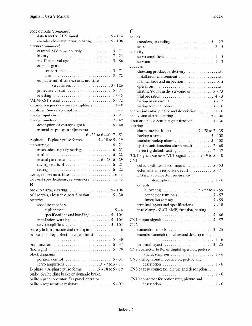
Sigma II User’s Manual Index
Index - 2
code outputs (continued)data transfer, SEN signal . . . . . . . . . . . . . . . 5 - 114encoder checksum error, clearing . . . . . . . . 5 - 108
alarms (continued)external 24V power supply . . . . . . . . . . . . . . 5 - 71history . . . . . . . . . . . . . . . . . . . . . . . . . . . . . . 7 - 25insufficient voltage . . . . . . . . . . . . . . . . . . . . 5 - 86output signals
connections . . . . . . . . . . . . . . . . . . . . . . . 5 - 71uses . . . . . . . . . . . . . . . . . . . . . . . . . . . . . 5 - 72
output terminal connections, multiple servodrives . . . . . . . . . . . . . . . . . . . 5 - 126
protective circuit . . . . . . . . . . . . . . . . . . . . . . 5 - 71resetting . . . . . . . . . . . . . . . . . . . . . . . . . . . . . . 7 - 5
/ALM-RST signal . . . . . . . . . . . . . . . . . . . . . . . . . 5 - 72ambient temperature, servo amplifiers . . . . . . . . . . 2 - 8amplifier. See servo amplifier. . . . . . . . . . . . . . . . . 1 - 4analog input circuit . . . . . . . . . . . . . . . . . . . . . . . . 3 - 21analog monitors . . . . . . . . . . . . . . . . . . . . . . . . . . . 7 - 49
description of voltage signals . . . . . . . . . . . . 6 - 40manual output gain adjustment . . . . . . . . . . . . . . . .
. . . . . . . . . . . . . . . . 6 - 33 to 6 - 40, 7 - 52A-phase + B-phase pulse forms . . . . . . .5 - 18 to 5 - 19auto-tuning . . . . . . . . . . . . . . . . . . . . . . . . . . . . . . 6 - 21
mechanical rigidity settings . . . . . . . . . . . . . . 6 - 23method . . . . . . . . . . . . . . . . . . . . . . . . . . . . . . 6 - 28related parameters . . . . . . . . . . . . . . . 6 - 28, 6 - 29saving results of . . . . . . . . . . . . . . . . . . . . . . . 6 - 25setting . . . . . . . . . . . . . . . . . . . . . . . . . . . . . . . 6 - 22
average movement filter . . . . . . . . . . . . . . . . . . . . . 6 - 3axis end specifications, servomotors . . . . . . . . . . . . 1 - 3Bbackup alarm, clearing . . . . . . . . . . . . . . . . . . . . 5 - 108ball screws, electronic gear function . . . . . . . . . . . 5 - 30batteries
absolute encodersreplacement . . . . . . . . . . . . . . . . . . . . . . . . 9 - 4specifications and handling . . . . . . . . . . 5 - 105
installation warning . . . . . . . . . . . . . . . . . . . 5 - 105servo amplifiers . . . . . . . . . . . . . . . . . . . . . . 5 - 105
battery holder, picture and description . . . . . . . . . . 1 - 6belts and pulleys, electronic gear function. . . . . . . . . . .
. . . . . . . . . . . . . . . . . . . . . . . . . . . . . . . . . 5 - 30bias function . . . . . . . . . . . . . . . . . . . . . . . . . . . . . 6 - 37/BK signal . . . . . . . . . . . . . . . . . . . . . . . . . . . . . . . 5 - 70block diagrams
position control . . . . . . . . . . . . . . . . . . . . . . . 5 - 31servo amplifiers . . . . . . . . . . . . . . . . .3 - 7 to 3 - 11
B-phase + A-phase pulse forms . . . . . . .5 - 18 to 5 - 19brake. See holding brake or dynamic brake.built-in panel operator. See panel operator.built-in regenerative resistors . . . . . . . . . . . . . . . . 5 - 92
Ccables
encoders, extending . . . . . . . . . . . . . . . . . . 5 - 127stress . . . . . . . . . . . . . . . . . . . . . . . . . . . . . . . . 2 - 5
capacityservo amplifiers . . . . . . . . . . . . . . . . . . . . . . . 1 - 5servomotors . . . . . . . . . . . . . . . . . . . . . . . . . . 1 - 3
cautionschecking product on delivery . . . . . . . . . . . . . . . .xiinstallation environment . . . . . . . . . . . . . . . . . . . .ximaintenance and inspection . . . . . . . . . . . . . . . xiiioperation . . . . . . . . . . . . . . . . . . . . . . . . . . . . . . . xiistarting/stopping the servomotor . . . . . . . . . 5 - 73trial operation . . . . . . . . . . . . . . . . . . . . . . . . . 4 - 3wiring main circuit . . . . . . . . . . . . . . . . . . . . 3 - 12wiring terminal block . . . . . . . . . . . . . . . . . . 3 - 16
charge indicator, picture and description . . . . . . . . 1 - 6check sum alarm, clearing . . . . . . . . . . . . . . . . . 5 - 108circular table, electronic gear function . . . . . . . . 5 - 30clearing
alarm traceback data . . . . . . . . . . . . 7 - 38 to 7 - 39backup alarms . . . . . . . . . . . . . . . . . . . . . . . 5 - 108encoder backup alarm . . . . . . . . . . . . . . . . . 5 - 108option unit detection alarm results . . . . . . . . 7 - 60restoring default settings . . . . . . . . . . . . . . . . 7 - 47
/CLT signal, see also /VLT signal . . . . . . 5 - 9 to 5 - 10CN1
default settings, list of inputs . . . . . . . . . . . . 5 - 53external alarm response circuit . . . . . . . . . . . 5 - 71I/O signal connector, picture and
description . . . . . . . . . . . . . . . . . . . . 1 - 6outputs
allocating . . . . . . . . . . . . . . . . . 5 - 57 to 5 - 59connector terminals . . . . . . . . . . . . . . . . 5 - 57inversion settings . . . . . . . . . . . . . . . . . . 5 - 59
terminal layout and specifications . . . . . . . . 3 - 18zero clamp (/Z-CLAMP) function, setting . . . . . . .
. . . . . . . . . . . . . . . . . . . . . . . . . . . . 5 - 66CN1 output signals . . . . . . . . . . . . . . . . . . . . . . . . 5 - 57CN2
connector models . . . . . . . . . . . . . . . . . . . . . 3 - 25encoder connector, picture and description . . . . . . .
. . . . . . . . . . . . . . . . . . . . . . . . . . . . . 1 - 6terminal layout . . . . . . . . . . . . . . . . . . . . . . . 3 - 25
CN3 connector to PC or digital operator, picture and description . . . . . . . . . . . . . . . . . . . . . 1 - 6
CN5 analog monitor connector, picture and description . . . . . . . . . . . . . . . . . . . . . . . . . 1 - 6
CN8 battery connector, picture and description . . . . . . . . . . . . . . . . . . . . . . . . . . . . . . . . . . . . . . . . . 1 - 6
CN10 connector for option unit, picture and description . . . . . . . . . . . . . . . . . . . . . . . . . 1 - 6
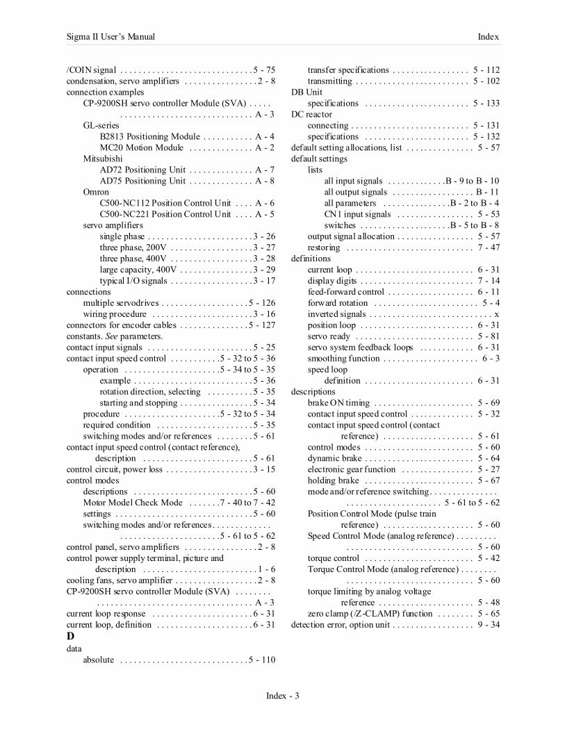
Sigma II User’s Manual Index
Index - 3
/COIN signal . . . . . . . . . . . . . . . . . . . . . . . . . . . . . 5 - 75condensation, servo amplifiers . . . . . . . . . . . . . . . . 2 - 8connection examples
CP-9200SH servo controller Module (SVA) . . . . . . . . . . . . . . . . . . . . . . . . . . . . . . . . . . A - 3
GL-seriesB2813 Positioning Module . . . . . . . . . . . A - 4MC20 Motion Module . . . . . . . . . . . . . . A - 2
MitsubishiAD72 Positioning Unit . . . . . . . . . . . . . . A - 7AD75 Positioning Unit . . . . . . . . . . . . . . A - 8
OmronC500-NC112 Position Control Unit . . . . A - 6C500-NC221 Position Control Unit . . . . A - 5
servo amplifierssingle phase . . . . . . . . . . . . . . . . . . . . . . . 3 - 26three phase, 200V . . . . . . . . . . . . . . . . . . 3 - 27three phase, 400V . . . . . . . . . . . . . . . . . . 3 - 28large capacity, 400V . . . . . . . . . . . . . . . . 3 - 29typical I/O signals . . . . . . . . . . . . . . . . . . 3 - 17
connectionsmultiple servodrives . . . . . . . . . . . . . . . . . . . 5 - 126wiring procedure . . . . . . . . . . . . . . . . . . . . . . 3 - 16
connectors for encoder cables . . . . . . . . . . . . . . . 5 - 127constants. See parameters.contact input signals . . . . . . . . . . . . . . . . . . . . . . . 5 - 25contact input speed control . . . . . . . . . . .5 - 32 to 5 - 36
operation . . . . . . . . . . . . . . . . . . . . .5 - 34 to 5 - 35example . . . . . . . . . . . . . . . . . . . . . . . . . . 5 - 36rotation direction, selecting . . . . . . . . . . 5 - 35starting and stopping . . . . . . . . . . . . . . . . 5 - 34
procedure . . . . . . . . . . . . . . . . . . . . .5 - 32 to 5 - 34required condition . . . . . . . . . . . . . . . . . . . . . 5 - 35switching modes and/or references . . . . . . . . 5 - 61
contact input speed control (contact reference), description . . . . . . . . . . . . . . . . . . . . . . . . 5 - 61
control circuit, power loss . . . . . . . . . . . . . . . . . . . 3 - 15control modes
descriptions . . . . . . . . . . . . . . . . . . . . . . . . . . 5 - 60Motor Model Check Mode . . . . . . .7 - 40 to 7 - 42settings . . . . . . . . . . . . . . . . . . . . . . . . . . . . . . 5 - 60switching modes and/or references . . . . . . . . . . . . .
. . . . . . . . . . . . . . . . . . . . . .5 - 61 to 5 - 62control panel, servo amplifiers . . . . . . . . . . . . . . . . 2 - 8control power supply terminal, picture and
description . . . . . . . . . . . . . . . . . . . . . . . . . 1 - 6cooling fans, servo amplifier . . . . . . . . . . . . . . . . . . 2 - 8CP-9200SH servo controller Module (SVA) . . . . . . . .
. . . . . . . . . . . . . . . . . . . . . . . . . . . . . . . . . . A - 3current loop response . . . . . . . . . . . . . . . . . . . . . . 6 - 31current loop, definition . . . . . . . . . . . . . . . . . . . . . 6 - 31Ddata
absolute . . . . . . . . . . . . . . . . . . . . . . . . . . . . 5 - 110
transfer specifications . . . . . . . . . . . . . . . . . 5 - 112transmitting . . . . . . . . . . . . . . . . . . . . . . . . . 5 - 102
DB Unitspecifications . . . . . . . . . . . . . . . . . . . . . . . 5 - 133
DC reactorconnecting . . . . . . . . . . . . . . . . . . . . . . . . . . 5 - 131specifications . . . . . . . . . . . . . . . . . . . . . . . 5 - 132
default setting allocations, list . . . . . . . . . . . . . . . 5 - 57default settings
listsall input signals . . . . . . . . . . . . .B - 9 to B - 10all output signals . . . . . . . . . . . . . . . . . . B - 11all parameters . . . . . . . . . . . . . . .B - 2 to B - 4CN1 input signals . . . . . . . . . . . . . . . . . 5 - 53switches . . . . . . . . . . . . . . . . . . . .B - 5 to B - 8
output signal allocation . . . . . . . . . . . . . . . . . 5 - 57restoring . . . . . . . . . . . . . . . . . . . . . . . . . . . . 7 - 47
definitionscurrent loop . . . . . . . . . . . . . . . . . . . . . . . . . . 6 - 31display digits . . . . . . . . . . . . . . . . . . . . . . . . . 7 - 14feed-forward control . . . . . . . . . . . . . . . . . . . 6 - 11forward rotation . . . . . . . . . . . . . . . . . . . . . . . 5 - 4inverted signals . . . . . . . . . . . . . . . . . . . . . . . . . . . xposition loop . . . . . . . . . . . . . . . . . . . . . . . . . 6 - 31servo ready . . . . . . . . . . . . . . . . . . . . . . . . . . 5 - 81servo system feedback loops . . . . . . . . . . . . 6 - 31smoothing function . . . . . . . . . . . . . . . . . . . . . 6 - 3speed loop
definition . . . . . . . . . . . . . . . . . . . . . . . . 6 - 31descriptions
brake ON timing . . . . . . . . . . . . . . . . . . . . . . 5 - 69contact input speed control . . . . . . . . . . . . . . 5 - 32contact input speed control (contact
reference) . . . . . . . . . . . . . . . . . . . . 5 - 61control modes . . . . . . . . . . . . . . . . . . . . . . . . 5 - 60dynamic brake . . . . . . . . . . . . . . . . . . . . . . . . 5 - 64electronic gear function . . . . . . . . . . . . . . . . 5 - 27holding brake . . . . . . . . . . . . . . . . . . . . . . . . 5 - 67mode and/or reference switching. . . . . . . . . . . . . . .
. . . . . . . . . . . . . . . . . . . . . 5 - 61 to 5 - 62Position Control Mode (pulse train
reference) . . . . . . . . . . . . . . . . . . . . 5 - 60Speed Control Mode (analog reference) . . . . . . . . .
. . . . . . . . . . . . . . . . . . . . . . . . . . . . 5 - 60torque control . . . . . . . . . . . . . . . . . . . . . . . . 5 - 42Torque Control Mode (analog reference) . . . . . . . .
. . . . . . . . . . . . . . . . . . . . . . . . . . . . 5 - 60torque limiting by analog voltage
reference . . . . . . . . . . . . . . . . . . . . . 5 - 48zero clamp (/Z-CLAMP) function . . . . . . . . 5 - 65
detection error, option unit . . . . . . . . . . . . . . . . . . 9 - 34
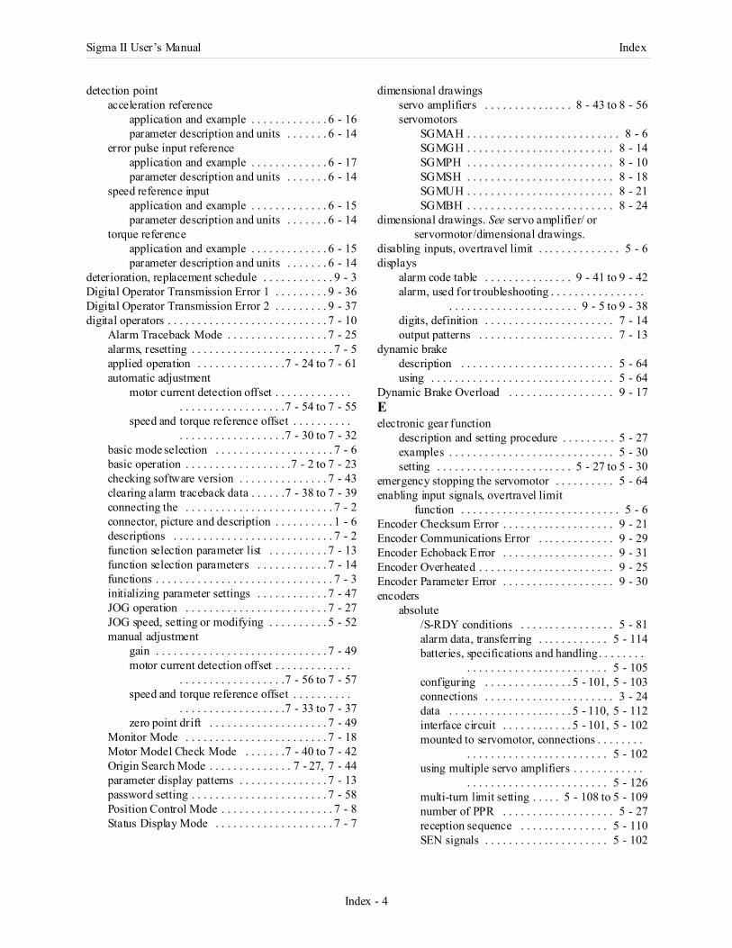
Sigma II User’s Manual Index
Index - 4
detection pointacceleration reference
application and example . . . . . . . . . . . . . 6 - 16parameter description and units . . . . . . . 6 - 14
error pulse input referenceapplication and example . . . . . . . . . . . . . 6 - 17parameter description and units . . . . . . . 6 - 14
speed reference inputapplication and example . . . . . . . . . . . . . 6 - 15parameter description and units . . . . . . . 6 - 14
torque referenceapplication and example . . . . . . . . . . . . . 6 - 15parameter description and units . . . . . . . 6 - 14
deterioration, replacement schedule . . . . . . . . . . . . 9 - 3Digital Operator Transmission Error 1 . . . . . . . . . 9 - 36Digital Operator Transmission Error 2 . . . . . . . . . 9 - 37digital operators . . . . . . . . . . . . . . . . . . . . . . . . . . . 7 - 10
Alarm Traceback Mode . . . . . . . . . . . . . . . . . 7 - 25alarms, resetting . . . . . . . . . . . . . . . . . . . . . . . . 7 - 5applied operation . . . . . . . . . . . . . . .7 - 24 to 7 - 61automatic adjustment
motor current detection offset . . . . . . . . . . . . . . . . . . . . . . . . . . . . . . .7 - 54 to 7 - 55
speed and torque reference offset . . . . . . . . . . . . . . . . . . . . . . . . . . . .7 - 30 to 7 - 32
basic mode selection . . . . . . . . . . . . . . . . . . . . 7 - 6basic operation . . . . . . . . . . . . . . . . . .7 - 2 to 7 - 23checking software version . . . . . . . . . . . . . . . 7 - 43clearing alarm traceback data . . . . . .7 - 38 to 7 - 39connecting the . . . . . . . . . . . . . . . . . . . . . . . . . 7 - 2connector, picture and description . . . . . . . . . . 1 - 6descriptions . . . . . . . . . . . . . . . . . . . . . . . . . . . 7 - 2function selection parameter list . . . . . . . . . . 7 - 13function selection parameters . . . . . . . . . . . . 7 - 14functions . . . . . . . . . . . . . . . . . . . . . . . . . . . . . . 7 - 3initializing parameter settings . . . . . . . . . . . . 7 - 47JOG operation . . . . . . . . . . . . . . . . . . . . . . . . 7 - 27JOG speed, setting or modifying . . . . . . . . . . 5 - 52manual adjustment
gain . . . . . . . . . . . . . . . . . . . . . . . . . . . . . 7 - 49motor current detection offset . . . . . . . . . . . . .
. . . . . . . . . . . . . . . . . .7 - 56 to 7 - 57speed and torque reference offset . . . . . . . . . .
. . . . . . . . . . . . . . . . . .7 - 33 to 7 - 37zero point drift . . . . . . . . . . . . . . . . . . . . 7 - 49
Monitor Mode . . . . . . . . . . . . . . . . . . . . . . . . 7 - 18Motor Model Check Mode . . . . . . .7 - 40 to 7 - 42Origin Search Mode . . . . . . . . . . . . . . 7 - 27, 7 - 44parameter display patterns . . . . . . . . . . . . . . . 7 - 13password setting . . . . . . . . . . . . . . . . . . . . . . . 7 - 58Position Control Mode . . . . . . . . . . . . . . . . . . . 7 - 8Status Display Mode . . . . . . . . . . . . . . . . . . . . 7 - 7
dimensional drawingsservo amplifiers . . . . . . . . . . . . . . . 8 - 43 to 8 - 56servomotors
SGMAH . . . . . . . . . . . . . . . . . . . . . . . . . . 8 - 6SGMGH . . . . . . . . . . . . . . . . . . . . . . . . . 8 - 14SGMPH . . . . . . . . . . . . . . . . . . . . . . . . . 8 - 10SGMSH . . . . . . . . . . . . . . . . . . . . . . . . . 8 - 18SGMUH . . . . . . . . . . . . . . . . . . . . . . . . . 8 - 21SGMBH . . . . . . . . . . . . . . . . . . . . . . . . . 8 - 24
dimensional drawings. See servo amplifier/ or servormotor/dimensional drawings.
disabling inputs, overtravel limit . . . . . . . . . . . . . . 5 - 6displays
alarm code table . . . . . . . . . . . . . . . 9 - 41 to 9 - 42alarm, used for troubleshooting . . . . . . . . . . . . . . . .
. . . . . . . . . . . . . . . . . . . . . . 9 - 5 to 9 - 38digits, definition . . . . . . . . . . . . . . . . . . . . . . 7 - 14output patterns . . . . . . . . . . . . . . . . . . . . . . . 7 - 13
dynamic brakedescription . . . . . . . . . . . . . . . . . . . . . . . . . . 5 - 64using . . . . . . . . . . . . . . . . . . . . . . . . . . . . . . . 5 - 64
Dynamic Brake Overload . . . . . . . . . . . . . . . . . . 9 - 17Eelectronic gear function
description and setting procedure . . . . . . . . . 5 - 27examples . . . . . . . . . . . . . . . . . . . . . . . . . . . . 5 - 30setting . . . . . . . . . . . . . . . . . . . . . . . 5 - 27 to 5 - 30
emergency stopping the servomotor . . . . . . . . . . 5 - 64enabling input signals, overtravel limit
function . . . . . . . . . . . . . . . . . . . . . . . . . . . 5 - 6Encoder Checksum Error . . . . . . . . . . . . . . . . . . . 9 - 21Encoder Communications Error . . . . . . . . . . . . . 9 - 29Encoder Echoback Error . . . . . . . . . . . . . . . . . . . 9 - 31Encoder Overheated . . . . . . . . . . . . . . . . . . . . . . . 9 - 25Encoder Parameter Error . . . . . . . . . . . . . . . . . . . 9 - 30encoders
absolute/S-RDY conditions . . . . . . . . . . . . . . . . 5 - 81alarm data, transferring . . . . . . . . . . . . 5 - 114batteries, specifications and handling. . . . . . . .
. . . . . . . . . . . . . . . . . . . . . . . . 5 - 105configuring . . . . . . . . . . . . . . . 5 - 101, 5 - 103connections . . . . . . . . . . . . . . . . . . . . . . 3 - 24data . . . . . . . . . . . . . . . . . . . . . 5 - 110, 5 - 112interface circuit . . . . . . . . . . . . 5 - 101, 5 - 102mounted to servomotor, connections . . . . . . . .
. . . . . . . . . . . . . . . . . . . . . . . . 5 - 102using multiple servo amplifiers . . . . . . . . . . . .
. . . . . . . . . . . . . . . . . . . . . . . . 5 - 126multi-turn limit setting . . . . . 5 - 108 to 5 - 109number of PPR . . . . . . . . . . . . . . . . . . . 5 - 27reception sequence . . . . . . . . . . . . . . . 5 - 110SEN signals . . . . . . . . . . . . . . . . . . . . . 5 - 102

Sigma II User’s Manual Index
Index - 5
encoders (continued)serial data specifications . . . . . . . . . . . . 5 - 112setup . . . . . . . . . . . . . . . . . . .5 - 106 to 5 - 108transmission sequence . . . . . . . . . . . . . 5 - 111
alarmsbackup, clearing . . . . . . . . . . . . . . . . . . 5 - 108checksum error . . . . . . . . . . . . . . . . . . . . 9 - 21resetting . . . . . . . . . . . . . . . . . . . . . . . . . . 5 - 72
cable connector kits . . . . . . . . . . . . . . . . . . . 5 - 127cables, preparing . . . . . . . . . . . . . . . . . . . . . 5 - 128check sum alarm, clearing . . . . . . . . . . . . . . 5 - 108connector models for servomotors . . . . . . . . . 3 - 25connector terminal layout and specifications,
CN1 . . . . . . . . . . . . . . . . . . . . . . . . . 3 - 18connector terminal layout, CN2 . . . . . . . . . . . 3 - 25connector, picture and description . . . . . . . . . . 1 - 6electronic gear function . . . . . . . . . . . . . . . . . 5 - 27extending cables . . . . . . . . . . . . . . . . . . . . . . 5 - 127incremental
connections . . . . . . . . . . . . . . . . . . . . . . . 3 - 24number of PPR . . . . . . . . . . . . . . . . . . . . 5 - 27
signal output . . . . . . . . . . . . . . . . . . . . . . . . . . 5 - 21I/O signals . . . . . . . . . . . . . . . . . . . . . . . . 5 - 22pulse divider setting . . . . . . . . . . . . . . . . 5 - 23
wiring to servo amplifier . . . . . . . . . . . . . . . . 3 - 24error counter, clear signal . . . . . . . . . . . . . . . . . . . 5 - 20error pulse
used as detection point . . . . . . . . . . . . . . . . . . 6 - 14overflow alarm . . . . . . . . . . . . . . . . . . . . . . . . 6 - 10setting . . . . . . . . . . . . . . . . . . . . . . . . . . . . . . . 5 - 76used as detection point . . . . . . . . . . . . . . . . . . 6 - 17
external interlock, /TGON signal . . . . . . . . . . . . . 5 - 79external power supply input, 24V . . . . . . . . . . . . . 5 - 25external regenerative resistors
terminal picture and description . . . . . . . . . . . 1 - 6external speed limit function . . . . . . . . . . . . . . . . . 5 - 43external torque limit
contact input . . . . . . . . . . . . . . . . . . . . . . . . . . 5 - 10forward run side . . . . . . . . . . . . . . . . . . . . . . . 5 - 49reverse run side . . . . . . . . . . . . . . . . . . . . . . . 5 - 49
Ffans, servo amplifier cooling . . . . . . . . . . . . . . . . . . 2 - 8feedback loops, definition . . . . . . . . . . . . . . . . . . . 6 - 31feedback pulse counter monitor display . . . . . . . . 7 - 22feed-forward control . . . . . . . . . . . . . . . . . . . . . . . 6 - 11feed-forward function . . . . . . . . . . . . . . . . . . . . . . 6 - 36
speed . . . . . . . . . . . . . . . . . . . . . . . . . . . . . . . 5 - 46torque . . . . . . . . . . . . . . . . . . . . . . . . . . . . . . . 5 - 44
filters, smoothing function . . . . . . . . . . . . . . . . . . . 6 - 3forward or forward external torque limit . . . . . . . . 5 - 9forward overtravel . . . . . . . . . . . . . . . . . . . . . . . . . . 5 - 5forward rotation
definition . . . . . . . . . . . . . . . . . . . . . . . . . . . . . 5 - 4reference pulse form . . . . . . . . . . . . . . . . . . . 5 - 18
forward run prohibited (/P-OT) signal . . . .7 - 27, 7 - 44friction compensation selection . . . . . . . . . . . . . . 6 - 29full-wave rectification . . . . . . . . . . . . . . . . . . . . . 8 - 35functions
list of auxiliary functions . . . . . . . . . . . . . . . B - 12bias, description . . . . . . . . . . . . . . . . . . . . . . 6 - 37selection
changing . . . . . . . . . . . . . . . . . 7 - 15 to 7 - 17list of parameter types . . . . . . . . . . . . . . 7 - 13
soft start . . . . . . . . . . . . . . . . . . . . . . . . . . . . . 6 - 2fuse capacity . . . . . . . . . . . . . . . . . . . . . . . . . . . 5 - 117Ggain
adjustmentconditions . . . . . . . . . . . . . . . . . . . . . . . . 6 - 5matching sensitivity . . . . . . . . . . . . . . . . 7 - 49procedure . . . . . . . . . . . . . . . . . . . . . . . . 6 - 18
position loop . . . . . . . . . . . . . . . . . . . . 6 - 5, 6 - 10, . . . . . . . . . . . . . . . . . 6 - 19, 6 - 20, 6 - 30
servo gain adjustment . . . . . . . . . . . 6 - 30 to 6 - 40setting
reference values . . . . . . . . . . . . . . . . . . . 6 - 38servo gain . . . . . . . . . . . . . . . . . . . . . . . . 6 - 9speed loop . . . . . . . . . . . . . . . . . . . . . . . . 6 - 9
speed loop . . . . . . . . . . . . . . . . . 6 - 5, 6 - 18, 6 - 20zero clamp . . . . . . . . . . . . . . . . . . . . . . . . . . . 6 - 10
gain adjustment functionmanual . . . . . . . . . . . . . . . . . . . . . . . . . . . . . 7 - 52using . . . . . . . . . . . . . . . . . . . . . . . . . . . . . . . 7 - 49
gear ratio, electronic gear function . . . . . . . . . . . 5 - 27general precautions . . . . . . . . . . . . . . . . . . . . . . . . . xiiiGL-series
B2813 Positioning Module . . . . . . . . . . . . . . . A - 4MC20 Motion Module . . . . . . . . . . . . . . . . . . A - 2
ground terminalspicture and description . . . . . . . . . . . . . . . . . . 1 - 6warning . . . . . . . . . . . . . . . . . . . . . . . . . . . . 5 - 104
groundingisolation of ground from output lines . . . . . . . . . . .
. . . . . . . . . . . . . . . . . . . . . . . . . . . 5 - 124motor frame . . . . . . . . . . . . . . . . . . . . . . . . 5 - 122noise control . . . . . . . . . . . . . . . . . . . . . . . . 5 - 123noise filter in an enclosure . . . . . . . . . . . . . 5 - 125servo alarm . . . . . . . . . . . . . . . . . . . . . . . . . . 5 - 71
Hhand-held digital operator. See digital operator.harmonic suppression . . . . . . . . . . . . . . . . . . . . 5 - 131High Load . . . . . . . . . . . . . . . . . . . . . . . . . . . . . . 9 - 15high rigidity, setting gain . . . . . . . . . . . . . . . . . . . 6 - 38high-speed positioning . . . . . . . . . . . . . . . . . . . . . . 6 - 9history, alarms . . . . . . . . . . . . . . . . . . . . . . . . . . . 7 - 25
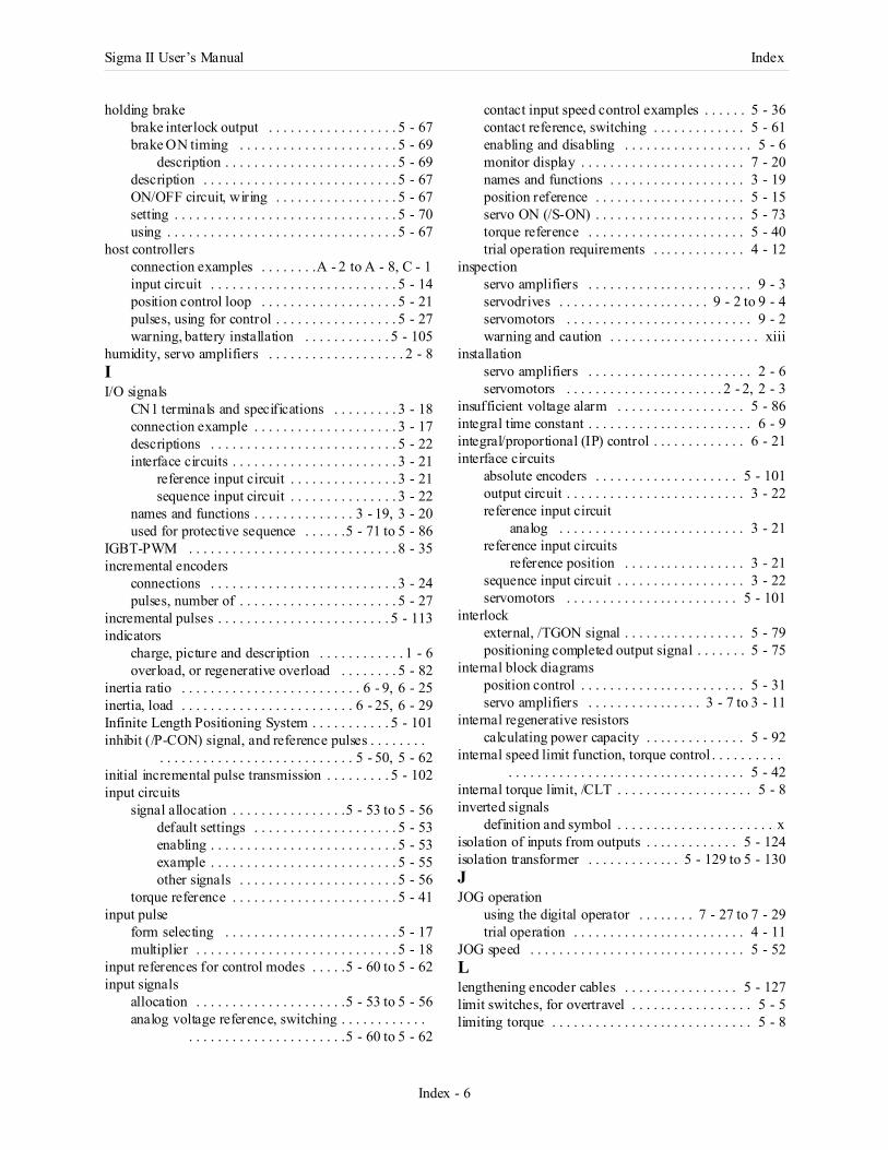
Sigma II User’s Manual Index
Index - 6
holding brakebrake interlock output . . . . . . . . . . . . . . . . . . 5 - 67brake ON timing . . . . . . . . . . . . . . . . . . . . . . 5 - 69
description . . . . . . . . . . . . . . . . . . . . . . . . 5 - 69description . . . . . . . . . . . . . . . . . . . . . . . . . . . 5 - 67ON/OFF circuit, wiring . . . . . . . . . . . . . . . . . 5 - 67setting . . . . . . . . . . . . . . . . . . . . . . . . . . . . . . . 5 - 70using . . . . . . . . . . . . . . . . . . . . . . . . . . . . . . . . 5 - 67
host controllersconnection examples . . . . . . . .A - 2 to A - 8, C - 1input circuit . . . . . . . . . . . . . . . . . . . . . . . . . . 5 - 14position control loop . . . . . . . . . . . . . . . . . . . 5 - 21pulses, using for control . . . . . . . . . . . . . . . . . 5 - 27warning, battery installation . . . . . . . . . . . . 5 - 105
humidity, servo amplifiers . . . . . . . . . . . . . . . . . . . 2 - 8II/O signals
CN1 terminals and specifications . . . . . . . . . 3 - 18connection example . . . . . . . . . . . . . . . . . . . . 3 - 17descriptions . . . . . . . . . . . . . . . . . . . . . . . . . . 5 - 22interface circuits . . . . . . . . . . . . . . . . . . . . . . . 3 - 21
reference input circuit . . . . . . . . . . . . . . . 3 - 21sequence input circuit . . . . . . . . . . . . . . . 3 - 22
names and functions . . . . . . . . . . . . . . 3 - 19, 3 - 20used for protective sequence . . . . . .5 - 71 to 5 - 86
IGBT-PWM . . . . . . . . . . . . . . . . . . . . . . . . . . . . . 8 - 35incremental encoders
connections . . . . . . . . . . . . . . . . . . . . . . . . . . 3 - 24pulses, number of . . . . . . . . . . . . . . . . . . . . . . 5 - 27
incremental pulses . . . . . . . . . . . . . . . . . . . . . . . . 5 - 113indicators
charge, picture and description . . . . . . . . . . . . 1 - 6overload, or regenerative overload . . . . . . . . 5 - 82
inertia ratio . . . . . . . . . . . . . . . . . . . . . . . . . 6 - 9, 6 - 25inertia, load . . . . . . . . . . . . . . . . . . . . . . . . 6 - 25, 6 - 29Infinite Length Positioning System . . . . . . . . . . . 5 - 101inhibit (/P-CON) signal, and reference pulses . . . . . . . .
. . . . . . . . . . . . . . . . . . . . . . . . . . . 5 - 50, 5 - 62initial incremental pulse transmission . . . . . . . . . 5 - 102input circuits
signal allocation . . . . . . . . . . . . . . . .5 - 53 to 5 - 56default settings . . . . . . . . . . . . . . . . . . . . 5 - 53enabling . . . . . . . . . . . . . . . . . . . . . . . . . . 5 - 53example . . . . . . . . . . . . . . . . . . . . . . . . . . 5 - 55other signals . . . . . . . . . . . . . . . . . . . . . . 5 - 56
torque reference . . . . . . . . . . . . . . . . . . . . . . . 5 - 41input pulse
form selecting . . . . . . . . . . . . . . . . . . . . . . . . 5 - 17multiplier . . . . . . . . . . . . . . . . . . . . . . . . . . . . 5 - 18
input references for control modes . . . . .5 - 60 to 5 - 62input signals
allocation . . . . . . . . . . . . . . . . . . . . .5 - 53 to 5 - 56analog voltage reference, switching . . . . . . . . . . . .
. . . . . . . . . . . . . . . . . . . . . .5 - 60 to 5 - 62
contact input speed control examples . . . . . . 5 - 36contact reference, switching . . . . . . . . . . . . . 5 - 61enabling and disabling . . . . . . . . . . . . . . . . . . 5 - 6monitor display . . . . . . . . . . . . . . . . . . . . . . . 7 - 20names and functions . . . . . . . . . . . . . . . . . . . 3 - 19position reference . . . . . . . . . . . . . . . . . . . . . 5 - 15servo ON (/S-ON) . . . . . . . . . . . . . . . . . . . . . 5 - 73torque reference . . . . . . . . . . . . . . . . . . . . . . 5 - 40trial operation requirements . . . . . . . . . . . . . 4 - 12
inspectionservo amplifiers . . . . . . . . . . . . . . . . . . . . . . . 9 - 3servodrives . . . . . . . . . . . . . . . . . . . . . 9 - 2 to 9 - 4servomotors . . . . . . . . . . . . . . . . . . . . . . . . . . 9 - 2warning and caution . . . . . . . . . . . . . . . . . . . . . xiii
installationservo amplifiers . . . . . . . . . . . . . . . . . . . . . . . 2 - 6servomotors . . . . . . . . . . . . . . . . . . . . . . 2 - 2, 2 - 3
insufficient voltage alarm . . . . . . . . . . . . . . . . . . 5 - 86integral time constant . . . . . . . . . . . . . . . . . . . . . . . 6 - 9integral/proportional (IP) control . . . . . . . . . . . . . 6 - 21interface circuits
absolute encoders . . . . . . . . . . . . . . . . . . . . 5 - 101output circuit . . . . . . . . . . . . . . . . . . . . . . . . . 3 - 22reference input circuit
analog . . . . . . . . . . . . . . . . . . . . . . . . . . 3 - 21reference input circuits
reference position . . . . . . . . . . . . . . . . . 3 - 21sequence input circuit . . . . . . . . . . . . . . . . . . 3 - 22servomotors . . . . . . . . . . . . . . . . . . . . . . . . 5 - 101
interlockexternal, /TGON signal . . . . . . . . . . . . . . . . . 5 - 79positioning completed output signal . . . . . . . 5 - 75
internal block diagramsposition control . . . . . . . . . . . . . . . . . . . . . . . 5 - 31servo amplifiers . . . . . . . . . . . . . . . . 3 - 7 to 3 - 11
internal regenerative resistorscalculating power capacity . . . . . . . . . . . . . . 5 - 92
internal speed limit function, torque control . . . . . . . . . . . . . . . . . . . . . . . . . . . . . . . . . . . . . . . . . . . 5 - 42
internal torque limit, /CLT . . . . . . . . . . . . . . . . . . . 5 - 8inverted signals
definition and symbol . . . . . . . . . . . . . . . . . . . . . . xisolation of inputs from outputs . . . . . . . . . . . . . 5 - 124isolation transformer . . . . . . . . . . . . . 5 - 129 to 5 - 130JJOG operation
using the digital operator . . . . . . . . 7 - 27 to 7 - 29trial operation . . . . . . . . . . . . . . . . . . . . . . . . 4 - 11
JOG speed . . . . . . . . . . . . . . . . . . . . . . . . . . . . . . 5 - 52Llengthening encoder cables . . . . . . . . . . . . . . . . 5 - 127limit switches, for overtravel . . . . . . . . . . . . . . . . . 5 - 5limiting torque . . . . . . . . . . . . . . . . . . . . . . . . . . . . 5 - 8
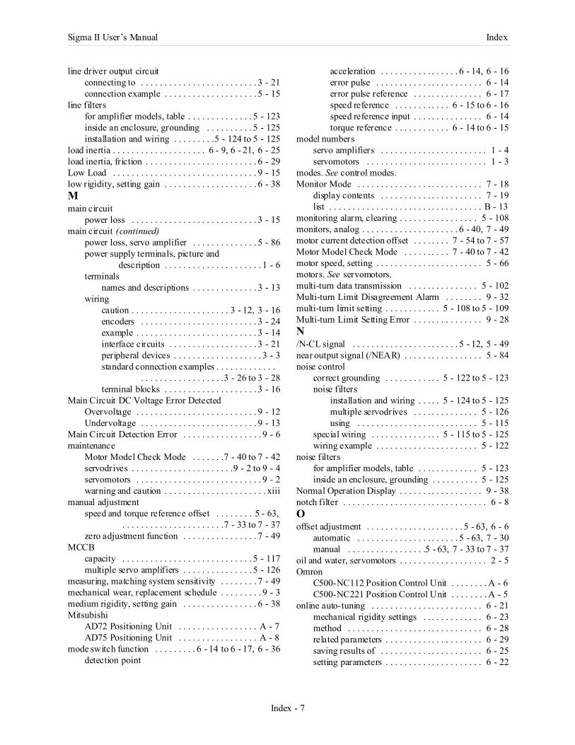
Sigma II User’s Manual Index
Index - 7
line driver output circuitconnecting to . . . . . . . . . . . . . . . . . . . . . . . . . 3 - 21connection example . . . . . . . . . . . . . . . . . . . . 5 - 15
line filtersfor amplifier models, table . . . . . . . . . . . . . . 5 - 123inside an enclosure, grounding . . . . . . . . . . 5 - 125installation and wiring . . . . . . . . .5 - 124 to 5 - 125
load inertia . . . . . . . . . . . . . . . . . . . . 6 - 9, 6 - 21, 6 - 25load inertia, friction . . . . . . . . . . . . . . . . . . . . . . . . 6 - 29Low Load . . . . . . . . . . . . . . . . . . . . . . . . . . . . . . . 9 - 15low rigidity, setting gain . . . . . . . . . . . . . . . . . . . . 6 - 38Mmain circuit
power loss . . . . . . . . . . . . . . . . . . . . . . . . . . . 3 - 15main circuit (continued)
power loss, servo amplifier . . . . . . . . . . . . . . 5 - 86power supply terminals, picture and
description . . . . . . . . . . . . . . . . . . . . . 1 - 6terminals
names and descriptions . . . . . . . . . . . . . . 3 - 13wiring
caution . . . . . . . . . . . . . . . . . . . . . 3 - 12, 3 - 16encoders . . . . . . . . . . . . . . . . . . . . . . . . . 3 - 24example . . . . . . . . . . . . . . . . . . . . . . . . . . 3 - 14interface circuits . . . . . . . . . . . . . . . . . . . 3 - 21peripheral devices . . . . . . . . . . . . . . . . . . . 3 - 3standard connection examples . . . . . . . . . . . . .
. . . . . . . . . . . . . . . . . .3 - 26 to 3 - 28terminal blocks . . . . . . . . . . . . . . . . . . . . 3 - 16
Main Circuit DC Voltage Error DetectedOvervoltage . . . . . . . . . . . . . . . . . . . . . . . . . . 9 - 12Undervoltage . . . . . . . . . . . . . . . . . . . . . . . . . 9 - 13
Main Circuit Detection Error . . . . . . . . . . . . . . . . . 9 - 6maintenance
Motor Model Check Mode . . . . . . .7 - 40 to 7 - 42servodrives . . . . . . . . . . . . . . . . . . . . . .9 - 2 to 9 - 4servomotors . . . . . . . . . . . . . . . . . . . . . . . . . . . 9 - 2warning and caution . . . . . . . . . . . . . . . . . . . . . . xiii
manual adjustmentspeed and torque reference offset . . . . . . . . 5 - 63,
. . . . . . . . . . . . . . . . . . . . . .7 - 33 to 7 - 37zero adjustment function . . . . . . . . . . . . . . . . 7 - 49
MCCBcapacity . . . . . . . . . . . . . . . . . . . . . . . . . . . . 5 - 117multiple servo amplifiers . . . . . . . . . . . . . . . 5 - 126
measuring, matching system sensitivity . . . . . . . . 7 - 49mechanical wear, replacement schedule . . . . . . . . . 9 - 3medium rigidity, setting gain . . . . . . . . . . . . . . . . 6 - 38Mitsubishi
AD72 Positioning Unit . . . . . . . . . . . . . . . . . A - 7AD75 Positioning Unit . . . . . . . . . . . . . . . . . A - 8
mode switch function . . . . . . . . . 6 - 14 to 6 - 17, 6 - 36detection point
acceleration . . . . . . . . . . . . . . . . . 6 - 14, 6 - 16error pulse . . . . . . . . . . . . . . . . . . . . . . . 6 - 14error pulse reference . . . . . . . . . . . . . . . 6 - 17speed reference . . . . . . . . . . . . 6 - 15 to 6 - 16speed reference input . . . . . . . . . . . . . . . 6 - 14torque reference . . . . . . . . . . . . 6 - 14 to 6 - 15
model numbersservo amplifiers . . . . . . . . . . . . . . . . . . . . . . . 1 - 4servomotors . . . . . . . . . . . . . . . . . . . . . . . . . . 1 - 3
modes. See control modes.Monitor Mode . . . . . . . . . . . . . . . . . . . . . . . . . . . 7 - 18
display contents . . . . . . . . . . . . . . . . . . . . . . 7 - 19list . . . . . . . . . . . . . . . . . . . . . . . . . . . . . . . . . B - 13
monitoring alarm, clearing . . . . . . . . . . . . . . . . . 5 - 108monitors, analog . . . . . . . . . . . . . . . . . . . . . 6 - 40, 7 - 49motor current detection offset . . . . . . . . 7 - 54 to 7 - 57Motor Model Check Mode . . . . . . . . . . 7 - 40 to 7 - 42motor speed, setting . . . . . . . . . . . . . . . . . . . . . . . 5 - 66motors. See servomotors.multi-turn data transmission . . . . . . . . . . . . . . . 5 - 102Multi-turn Limit Disagreement Alarm . . . . . . . . 9 - 32multi-turn limit setting . . . . . . . . . . . . 5 - 108 to 5 - 109Multi-turn Limit Setting Error . . . . . . . . . . . . . . . 9 - 28N/N-CL signal . . . . . . . . . . . . . . . . . . . . . . . 5 - 12, 5 - 49near output signal (/NEAR) . . . . . . . . . . . . . . . . . 5 - 84noise control
correct grounding . . . . . . . . . . . . 5 - 122 to 5 - 123noise filters
installation and wiring . . . . . 5 - 124 to 5 - 125multiple servodrives . . . . . . . . . . . . . . 5 - 126using . . . . . . . . . . . . . . . . . . . . . . . . . . 5 - 115
special wiring . . . . . . . . . . . . . . . 5 - 115 to 5 - 125wiring example . . . . . . . . . . . . . . . . . . . . . . 5 - 122
noise filtersfor amplifier models, table . . . . . . . . . . . . . 5 - 123inside an enclosure, grounding . . . . . . . . . . 5 - 125
Normal Operation Display . . . . . . . . . . . . . . . . . . 9 - 38notch filter . . . . . . . . . . . . . . . . . . . . . . . . . . . . . . . 6 - 8Ooffset adjustment . . . . . . . . . . . . . . . . . . . . . 5 - 63, 6 - 6
automatic . . . . . . . . . . . . . . . . . . . . . . 5 - 63, 7 - 30manual . . . . . . . . . . . . . . . . .5 - 63, 7 - 33 to 7 - 37
oil and water, servomotors . . . . . . . . . . . . . . . . . . . 2 - 5Omron
C500-NC112 Position Control Unit . . . . . . . . A - 6C500-NC221 Position Control Unit . . . . . . . . A - 5
online auto-tuning . . . . . . . . . . . . . . . . . . . . . . . . 6 - 21mechanical rigidity settings . . . . . . . . . . . . . 6 - 23method . . . . . . . . . . . . . . . . . . . . . . . . . . . . . 6 - 28related parameters . . . . . . . . . . . . . . . . . . . . . 6 - 29saving results of . . . . . . . . . . . . . . . . . . . . . . 6 - 25setting parameters . . . . . . . . . . . . . . . . . . . . . 6 - 22
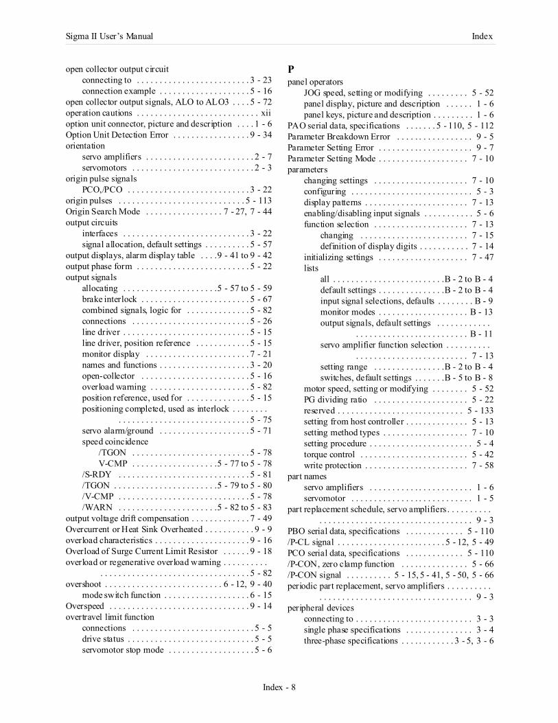
Sigma II User’s Manual Index
Index - 8
open collector output circuitconnecting to . . . . . . . . . . . . . . . . . . . . . . . . . 3 - 23connection example . . . . . . . . . . . . . . . . . . . . 5 - 16
open collector output signals, ALO to ALO3 . . . . 5 - 72operation cautions . . . . . . . . . . . . . . . . . . . . . . . . . . . xiioption unit connector, picture and description . . . . 1 - 6Option Unit Detection Error . . . . . . . . . . . . . . . . . 9 - 34orientation
servo amplifiers . . . . . . . . . . . . . . . . . . . . . . . . 2 - 7servomotors . . . . . . . . . . . . . . . . . . . . . . . . . . . 2 - 3
origin pulse signalsPCO,/PCO . . . . . . . . . . . . . . . . . . . . . . . . . . . 3 - 22
origin pulses . . . . . . . . . . . . . . . . . . . . . . . . . . . . 5 - 113Origin Search Mode . . . . . . . . . . . . . . . . . 7 - 27, 7 - 44output circuits
interfaces . . . . . . . . . . . . . . . . . . . . . . . . . . . . 3 - 22signal allocation, default settings . . . . . . . . . . 5 - 57
output displays, alarm display table . . . .9 - 41 to 9 - 42output phase form . . . . . . . . . . . . . . . . . . . . . . . . . 5 - 22output signals
allocating . . . . . . . . . . . . . . . . . . . . .5 - 57 to 5 - 59brake interlock . . . . . . . . . . . . . . . . . . . . . . . . 5 - 67combined signals, logic for . . . . . . . . . . . . . . 5 - 82connections . . . . . . . . . . . . . . . . . . . . . . . . . . 5 - 26line driver . . . . . . . . . . . . . . . . . . . . . . . . . . . . 5 - 15line driver, position reference . . . . . . . . . . . . 5 - 15monitor display . . . . . . . . . . . . . . . . . . . . . . . 7 - 21names and functions . . . . . . . . . . . . . . . . . . . . 3 - 20open-collector . . . . . . . . . . . . . . . . . . . . . . . . 5 - 16overload warning . . . . . . . . . . . . . . . . . . . . . . 5 - 82position reference, used for . . . . . . . . . . . . . . 5 - 15positioning completed, used as interlock . . . . . . . .
. . . . . . . . . . . . . . . . . . . . . . . . . . . . . 5 - 75servo alarm/ground . . . . . . . . . . . . . . . . . . . . 5 - 71speed coincidence
/TGON . . . . . . . . . . . . . . . . . . . . . . . . . . 5 - 78V-CMP . . . . . . . . . . . . . . . . . . .5 - 77 to 5 - 78
/S-RDY . . . . . . . . . . . . . . . . . . . . . . . . . . . . . 5 - 81/TGON . . . . . . . . . . . . . . . . . . . . . . .5 - 79 to 5 - 80/V-CMP . . . . . . . . . . . . . . . . . . . . . . . . . . . . . 5 - 78/WARN . . . . . . . . . . . . . . . . . . . . . .5 - 82 to 5 - 83
output voltage drift compensation . . . . . . . . . . . . . 7 - 49Overcurrent or Heat Sink Overheated . . . . . . . . . . . 9 - 9overload characteristics . . . . . . . . . . . . . . . . . . . . . 9 - 16Overload of Surge Current Limit Resistor . . . . . . 9 - 18overload or regenerative overload warning . . . . . . . . . .
. . . . . . . . . . . . . . . . . . . . . . . . . . . . . . . . . 5 - 82overshoot . . . . . . . . . . . . . . . . . . . . . . . . . . 6 - 12, 9 - 40
mode switch function . . . . . . . . . . . . . . . . . . . 6 - 15Overspeed . . . . . . . . . . . . . . . . . . . . . . . . . . . . . . . 9 - 14overtravel limit function
connections . . . . . . . . . . . . . . . . . . . . . . . . . . . 5 - 5drive status . . . . . . . . . . . . . . . . . . . . . . . . . . . . 5 - 5servomotor stop mode . . . . . . . . . . . . . . . . . . . 5 - 6
Ppanel operators
JOG speed, setting or modifying . . . . . . . . . 5 - 52panel display, picture and description . . . . . . 1 - 6panel keys, picture and description . . . . . . . . . 1 - 6
PAO serial data, specifications . . . . . . . 5 - 110, 5 - 112Parameter Breakdown Error . . . . . . . . . . . . . . . . . 9 - 5Parameter Setting Error . . . . . . . . . . . . . . . . . . . . . 9 - 7Parameter Setting Mode . . . . . . . . . . . . . . . . . . . . 7 - 10parameters
changing settings . . . . . . . . . . . . . . . . . . . . . 7 - 10configuring . . . . . . . . . . . . . . . . . . . . . . . . . . . 5 - 3display patterns . . . . . . . . . . . . . . . . . . . . . . . 7 - 13enabling/disabling input signals . . . . . . . . . . . 5 - 6function selection . . . . . . . . . . . . . . . . . . . . . 7 - 13
changing . . . . . . . . . . . . . . . . . . . . . . . . 7 - 15definition of display digits . . . . . . . . . . . 7 - 14
initializing settings . . . . . . . . . . . . . . . . . . . . 7 - 47lists
all . . . . . . . . . . . . . . . . . . . . . . . . .B - 2 to B - 4default settings . . . . . . . . . . . . . . .B - 2 to B - 4input signal selections, defaults . . . . . . . . B - 9monitor modes . . . . . . . . . . . . . . . . . . . . B - 13output signals, default settings . . . . . . . . . . . .
. . . . . . . . . . . . . . . . . . . . . . . . . B - 11servo amplifier function selection . . . . . . . . . .
. . . . . . . . . . . . . . . . . . . . . . . . . 7 - 13setting range . . . . . . . . . . . . . . . .B - 2 to B - 4switches, default settings . . . . . . .B - 5 to B - 8
motor speed, setting or modifying . . . . . . . . 5 - 52PG dividing ratio . . . . . . . . . . . . . . . . . . . . . 5 - 22reserved . . . . . . . . . . . . . . . . . . . . . . . . . . . . 5 - 133setting from host controller . . . . . . . . . . . . . . 5 - 13setting method types . . . . . . . . . . . . . . . . . . . 7 - 10setting procedure . . . . . . . . . . . . . . . . . . . . . . . 5 - 4torque control . . . . . . . . . . . . . . . . . . . . . . . . 5 - 42write protection . . . . . . . . . . . . . . . . . . . . . . . 7 - 58
part namesservo amplifiers . . . . . . . . . . . . . . . . . . . . . . . 1 - 6servomotor . . . . . . . . . . . . . . . . . . . . . . . . . . . 1 - 5
part replacement schedule, servo amplifiers . . . . . . . . . . . . . . . . . . . . . . . . . . . . . . . . . . . . . . . . . . . . 9 - 3
PBO serial data, specifications . . . . . . . . . . . . . 5 - 110/P-CL signal . . . . . . . . . . . . . . . . . . . . . . . . 5 - 12, 5 - 49PCO serial data, specifications . . . . . . . . . . . . . 5 - 110/P-CON, zero clamp function . . . . . . . . . . . . . . . 5 - 66/P-CON signal . . . . . . . . . . 5 - 15, 5 - 41, 5 - 50, 5 - 66periodic part replacement, servo amplifiers . . . . . . . . . .
. . . . . . . . . . . . . . . . . . . . . . . . . . . . . . . . . . 9 - 3peripheral devices
connecting to . . . . . . . . . . . . . . . . . . . . . . . . . . 3 - 3single phase specifications . . . . . . . . . . . . . . . 3 - 4three-phase specifications . . . . . . . . . . . . 3 - 5, 3 - 6
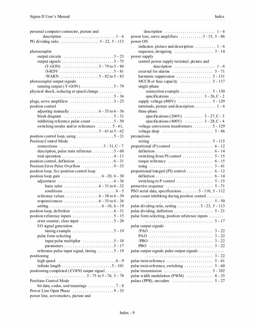
Sigma II User’s Manual Index
Index - 9
personal computer connector, picture and description . . . . . . . . . . . . . . . . . . . . . . . . . 1 - 6
PG dividing ratio . . . . . . . . . . . . . . . . . . . 5 - 22, 5 - 113
photocoupleroutput circuits . . . . . . . . . . . . . . . . . . . . . . . . 3 - 23output signals . . . . . . . . . . . . . . . . . . . . . . . . . 5 - 75
(T-GON) . . . . . . . . . . . . . . . . . .5 - 79 to 5 - 80/S-RDY . . . . . . . . . . . . . . . . . . . . . . . . . . 5 - 81/WARN . . . . . . . . . . . . . . . . . . .5 - 82 to 5 - 83
photocoupler output signalsrunning output (/T-GON) . . . . . . . . . . . . . . . . 5 - 79
physical shock, reducing at speed change . . . . . . . . . . . . . . . . . . . . . . . . . . . . . . . . . . . . . . . . . . . . 5 - 36
plugs, servo amplifiers . . . . . . . . . . . . . . . . . . . . . 3 - 25position control
adjusting manually . . . . . . . . . . . . . .6 - 35 to 6 - 36block diagram . . . . . . . . . . . . . . . . . . . . . . . . 5 - 31inhibiting reference pulse count . . . . . . . . . . . 5 - 50switching modes and/or references . . . . . . . 5 - 61,
. . . . . . . . . . . . . . . . . . . . . .5 - 61 to 5 - 62position control loop, using . . . . . . . . . . . . . . . . . . 5 - 21Position Control Mode
connections . . . . . . . . . . . . . . . . . . . . . 3 - 31, C - 7description, pulse train reference . . . . . . . . . . 5 - 60trial operation . . . . . . . . . . . . . . . . . . . . . . . . . 4 - 11
position control, definition . . . . . . . . . . . . . . . . . . 6 - 31Position Error Pulse Overflow . . . . . . . . . . . . . . . 9 - 33position loop. See position control loop.position loop gain . . . . . . . . . . . . . . . . . . . 6 - 20, 6 - 30
adjustment . . . . . . . . . . . . . . . . . . . . . . . . . . . 6 - 36basic rules . . . . . . . . . . . . . . . . .6 - 31 to 6 - 32conditions . . . . . . . . . . . . . . . . . . . . . . . . . 6 - 5
reference values . . . . . . . . . . . . . . . .6 - 38 to 6 - 39responsiveness . . . . . . . . . . . . . . . . .6 - 35 to 6 - 36setting . . . . . . . . . . . . . . . . . . . . . . . . . 6 - 10, 6 - 19
position loop, definition . . . . . . . . . . . . . . . . . . . . 6 - 31position reference inputs . . . . . . . . . . . . . . . . . . . . 5 - 15
error counter, clear input . . . . . . . . . . . . . . . . 5 - 20I/O signal generation
timing example . . . . . . . . . . . . . . . . . . . . 5 - 19pulse form selecting
input pulse multiplier . . . . . . . . . . . . . . . 5 - 18parameters . . . . . . . . . . . . . . . . . . . . . . . . 5 - 17
reference pulse input signal, timing . . . . . . . . 5 - 19positioning
high speed . . . . . . . . . . . . . . . . . . . . . . . . . . . . 6 - 9infinite length . . . . . . . . . . . . . . . . . . . . . . . . 5 - 101
positioning completed (/COIN) output signal . . . . . . . . . . . . . . . . . . . . . . . . . . . . 5 - 75 to 5 - 76, 5 - 78
Postition Control Modebit data, codes, and meanings . . . . . . . . . . . . . 7 - 8
Power Line Open Phase . . . . . . . . . . . . . . . . . . . . 9 - 35power line, servomotors, picture and
description . . . . . . . . . . . . . . . . . . . . . . . . . 1 - 6power loss, servo amplifiers . . . . . . . . . . . 3 - 15, 5 - 86power ON
indicator, picture and description . . . . . . . . . . 1 - 6sequence, designing . . . . . . . . . . . . . . . . . . . 3 - 14
power supplycontrol power supply terminal, picture and
description . . . . . . . . . . . . . . . . . . . . 1 - 6external for alarms . . . . . . . . . . . . . . . . . . . . 5 - 71harmonic suppression . . . . . . . . . . . . . . . . . 5 - 131MCCB or fuse capacity . . . . . . . . . . . . . . . 5 - 117single-phase
connection example . . . . . . . . . . . . . . . 5 - 130specifications . . . . . . . . . . . . . . . . 3 - 26, C - 2
supply voltage (400V) . . . . . . . . . . . . . . . . 5 - 129terminals, picture and description . . . . . . . . . . 1 - 6three-phase
specifications (200V) . . . . . . . . . 3 - 27, C - 3specifications (400V) . . . . . . . . . 3 - 28, C - 4
voltage conversion transformers . . . . . . . . . 5 - 129voltage drop . . . . . . . . . . . . . . . . . . . . . . . . . 5 - 86
precautionswiring . . . . . . . . . . . . . . . . . . . . . . . . . . . . . 5 - 115
proportional (P) control . . . . . . . . . . . . . . . . . . . . 6 - 12definition . . . . . . . . . . . . . . . . . . . . . . . . . . . . 6 - 14switching from PI control . . . . . . . . . . . . . . . 5 - 15torque reference . . . . . . . . . . . . . . . . . . . . . . 6 - 15using . . . . . . . . . . . . . . . . . . . . . . . . . . . . . . . 5 - 41
proportional/integral (PI) control . . . . . . . . . . . . . 6 - 12definition . . . . . . . . . . . . . . . . . . . . . . . . . . . . 6 - 14switching to P control . . . . . . . . . . . . . . . . . . 5 - 15
protective sequence . . . . . . . . . . . . . . . . . . . . . . . 5 - 71PSO serial data, specifications . . . . . . . . 5 - 110, 5 - 112pulse count inhibiting during position control . . . . . . . .
. . . . . . . . . . . . . . . . . . . . . . . . . . . . . . . . . 5 - 50pulse dividing ratio, setting . . . . . . . . . . . 5 - 23, 5 - 113pulse dividing, definition . . . . . . . . . . . . . . . . . . . 5 - 21pulse form selecting, position reference inputs . . . . . . .
. . . . . . . . . . . . . . . . . . . . . . . . . . . . . . . . . 5 - 17pulse output signals
/PAO . . . . . . . . . . . . . . . . . . . . . . . . . . . . . . . 3 - 22PAO . . . . . . . . . . . . . . . . . . . . . . . . . . . . . . . 3 - 22/PBO . . . . . . . . . . . . . . . . . . . . . . . . . . . . . . . 3 - 22PBO . . . . . . . . . . . . . . . . . . . . . . . . . . . . . . . 3 - 22
pulse output signals pulse output signals . . . . . . . . . . . . . . . . . . . . . . . . . . . . . . . . . . . . . . . . . . . . . 3 - 22
pulse train reference . . . . . . . . . . . . . . . . . . . . . . . 5 - 61pulse train reference, switching . . . . . . . . . . . . . . 5 - 60pulse transmission . . . . . . . . . . . . . . . . . . . . . . . 5 - 102pulse width modulation (PWM) . . . . . . . . . . . . . 8 - 35pulses (PPR), encoders . . . . . . . . . . . . . . . . . . . . 5 - 27
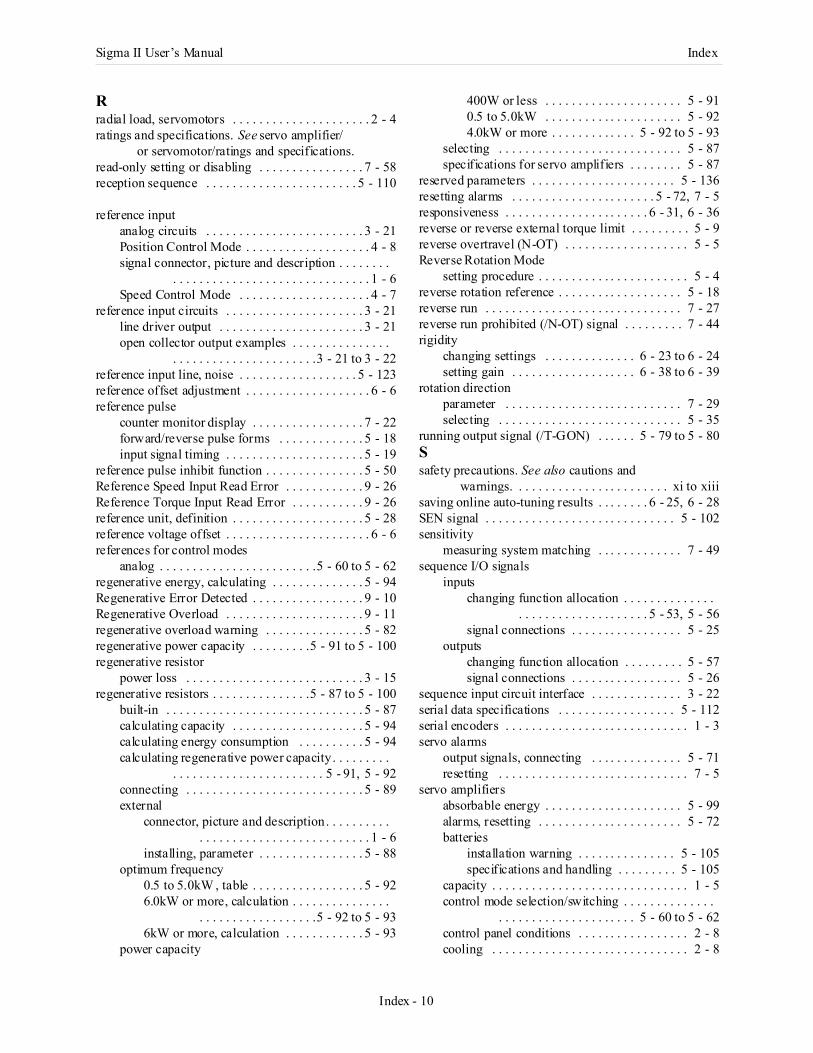
Sigma II User’s Manual Index
Index - 10
Rradial load, servomotors . . . . . . . . . . . . . . . . . . . . . 2 - 4ratings and specifications. See servo amplifier/
or servomotor/ratings and specifications.read-only setting or disabling . . . . . . . . . . . . . . . . 7 - 58reception sequence . . . . . . . . . . . . . . . . . . . . . . . 5 - 110
reference inputanalog circuits . . . . . . . . . . . . . . . . . . . . . . . . 3 - 21Position Control Mode . . . . . . . . . . . . . . . . . . . 4 - 8signal connector, picture and description . . . . . . . .
. . . . . . . . . . . . . . . . . . . . . . . . . . . . . . 1 - 6Speed Control Mode . . . . . . . . . . . . . . . . . . . . 4 - 7
reference input circuits . . . . . . . . . . . . . . . . . . . . . 3 - 21line driver output . . . . . . . . . . . . . . . . . . . . . . 3 - 21open collector output examples . . . . . . . . . . . . . . .
. . . . . . . . . . . . . . . . . . . . . .3 - 21 to 3 - 22reference input line, noise . . . . . . . . . . . . . . . . . . 5 - 123reference offset adjustment . . . . . . . . . . . . . . . . . . . 6 - 6reference pulse
counter monitor display . . . . . . . . . . . . . . . . . 7 - 22forward/reverse pulse forms . . . . . . . . . . . . . 5 - 18input signal timing . . . . . . . . . . . . . . . . . . . . . 5 - 19
reference pulse inhibit function . . . . . . . . . . . . . . . 5 - 50Reference Speed Input Read Error . . . . . . . . . . . . 9 - 26Reference Torque Input Read Error . . . . . . . . . . . 9 - 26reference unit, definition . . . . . . . . . . . . . . . . . . . . 5 - 28reference voltage offset . . . . . . . . . . . . . . . . . . . . . . 6 - 6references for control modes
analog . . . . . . . . . . . . . . . . . . . . . . . .5 - 60 to 5 - 62regenerative energy, calculating . . . . . . . . . . . . . . 5 - 94Regenerative Error Detected . . . . . . . . . . . . . . . . . 9 - 10Regenerative Overload . . . . . . . . . . . . . . . . . . . . . 9 - 11regenerative overload warning . . . . . . . . . . . . . . . 5 - 82regenerative power capacity . . . . . . . . .5 - 91 to 5 - 100regenerative resistor
power loss . . . . . . . . . . . . . . . . . . . . . . . . . . . 3 - 15regenerative resistors . . . . . . . . . . . . . . .5 - 87 to 5 - 100
built-in . . . . . . . . . . . . . . . . . . . . . . . . . . . . . . 5 - 87calculating capacity . . . . . . . . . . . . . . . . . . . . 5 - 94calculating energy consumption . . . . . . . . . . 5 - 94calculating regenerative power capacity . . . . . . . . .
. . . . . . . . . . . . . . . . . . . . . . . 5 - 91, 5 - 92connecting . . . . . . . . . . . . . . . . . . . . . . . . . . . 5 - 89external
connector, picture and description. . . . . . . . . . . . . . . . . . . . . . . . . . . . . . . . . . . . 1 - 6
installing, parameter . . . . . . . . . . . . . . . . 5 - 88optimum frequency
0.5 to 5.0kW , table . . . . . . . . . . . . . . . . . 5 - 926.0kW or more, calculation . . . . . . . . . . . . . . .
. . . . . . . . . . . . . . . . . .5 - 92 to 5 - 936kW or more, calculation . . . . . . . . . . . . 5 - 93
power capacity
400W or less . . . . . . . . . . . . . . . . . . . . . 5 - 910.5 to 5.0kW . . . . . . . . . . . . . . . . . . . . . 5 - 924.0kW or more . . . . . . . . . . . . . 5 - 92 to 5 - 93
selecting . . . . . . . . . . . . . . . . . . . . . . . . . . . . 5 - 87specifications for servo amplifiers . . . . . . . . 5 - 87
reserved parameters . . . . . . . . . . . . . . . . . . . . . . 5 - 136resetting alarms . . . . . . . . . . . . . . . . . . . . . . 5 - 72, 7 - 5responsiveness . . . . . . . . . . . . . . . . . . . . . . 6 - 31, 6 - 36reverse or reverse external torque limit . . . . . . . . . 5 - 9reverse overtravel (N-OT) . . . . . . . . . . . . . . . . . . . 5 - 5Reverse Rotation Mode
setting procedure . . . . . . . . . . . . . . . . . . . . . . . 5 - 4reverse rotation reference . . . . . . . . . . . . . . . . . . . 5 - 18reverse run . . . . . . . . . . . . . . . . . . . . . . . . . . . . . . 7 - 27reverse run prohibited (/N-OT) signal . . . . . . . . . 7 - 44rigidity
changing settings . . . . . . . . . . . . . . 6 - 23 to 6 - 24setting gain . . . . . . . . . . . . . . . . . . . 6 - 38 to 6 - 39
rotation directionparameter . . . . . . . . . . . . . . . . . . . . . . . . . . . 7 - 29selecting . . . . . . . . . . . . . . . . . . . . . . . . . . . . 5 - 35
running output signal (/T-GON) . . . . . . 5 - 79 to 5 - 80Ssafety precautions. See also cautions and
warnings. . . . . . . . . . . . . . . . . . . . . . . . xi to xiiisaving online auto-tuning results . . . . . . . . 6 - 25, 6 - 28SEN signal . . . . . . . . . . . . . . . . . . . . . . . . . . . . . 5 - 102sensitivity
measuring system matching . . . . . . . . . . . . . 7 - 49sequence I/O signals
inputschanging function allocation . . . . . . . . . . . . . .
. . . . . . . . . . . . . . . . . . . . 5 - 53, 5 - 56signal connections . . . . . . . . . . . . . . . . . 5 - 25
outputschanging function allocation . . . . . . . . . 5 - 57signal connections . . . . . . . . . . . . . . . . . 5 - 26
sequence input circuit interface . . . . . . . . . . . . . . 3 - 22serial data specifications . . . . . . . . . . . . . . . . . . 5 - 112serial encoders . . . . . . . . . . . . . . . . . . . . . . . . . . . . 1 - 3servo alarms
output signals, connecting . . . . . . . . . . . . . . 5 - 71resetting . . . . . . . . . . . . . . . . . . . . . . . . . . . . . 7 - 5
servo amplifiersabsorbable energy . . . . . . . . . . . . . . . . . . . . . 5 - 99alarms, resetting . . . . . . . . . . . . . . . . . . . . . . 5 - 72batteries
installation warning . . . . . . . . . . . . . . . 5 - 105specifications and handling . . . . . . . . . 5 - 105
capacity . . . . . . . . . . . . . . . . . . . . . . . . . . . . . . 1 - 5control mode selection/switching . . . . . . . . . . . . . .
. . . . . . . . . . . . . . . . . . . . . 5 - 60 to 5 - 62control panel conditions . . . . . . . . . . . . . . . . . 2 - 8cooling . . . . . . . . . . . . . . . . . . . . . . . . . . . . . . 2 - 8
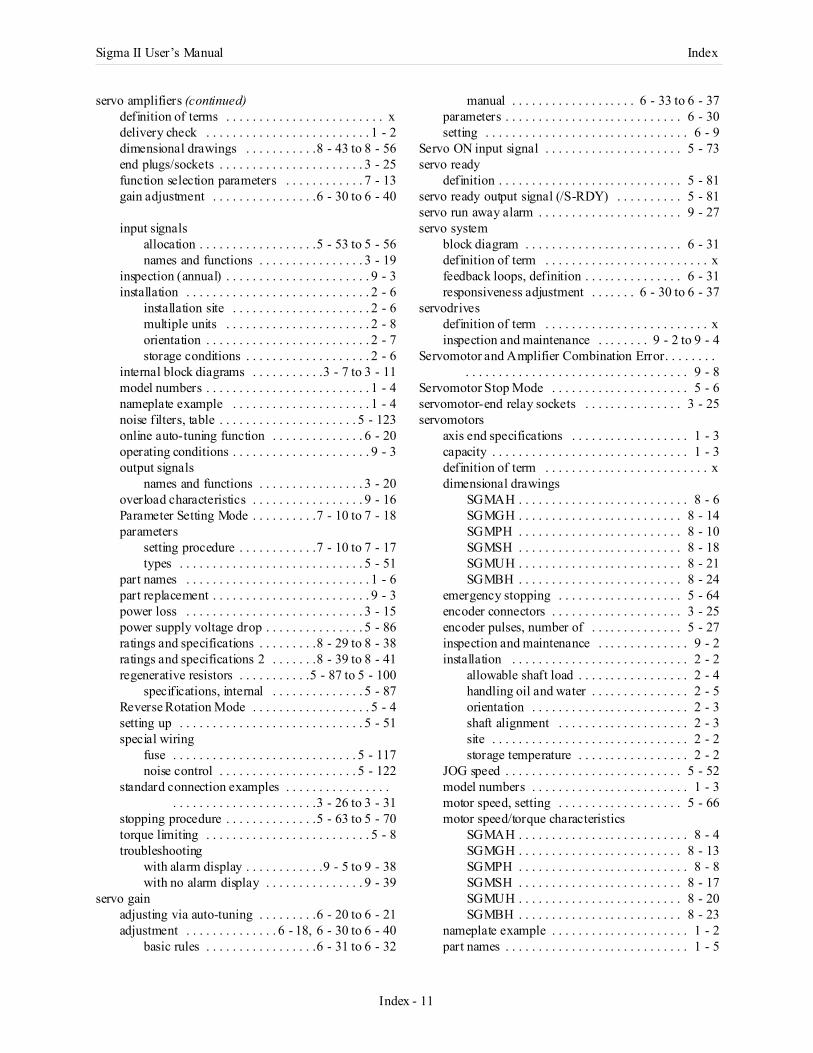
Sigma II User’s Manual Index
Index - 11
servo amplifiers (continued)definition of terms . . . . . . . . . . . . . . . . . . . . . . . . xdelivery check . . . . . . . . . . . . . . . . . . . . . . . . . 1 - 2dimensional drawings . . . . . . . . . . .8 - 43 to 8 - 56end plugs/sockets . . . . . . . . . . . . . . . . . . . . . . 3 - 25function selection parameters . . . . . . . . . . . . 7 - 13gain adjustment . . . . . . . . . . . . . . . .6 - 30 to 6 - 40
input signalsallocation . . . . . . . . . . . . . . . . . .5 - 53 to 5 - 56names and functions . . . . . . . . . . . . . . . . 3 - 19
inspection (annual) . . . . . . . . . . . . . . . . . . . . . . 9 - 3installation . . . . . . . . . . . . . . . . . . . . . . . . . . . . 2 - 6
installation site . . . . . . . . . . . . . . . . . . . . . 2 - 6multiple units . . . . . . . . . . . . . . . . . . . . . . 2 - 8orientation . . . . . . . . . . . . . . . . . . . . . . . . . 2 - 7storage conditions . . . . . . . . . . . . . . . . . . . 2 - 6
internal block diagrams . . . . . . . . . . .3 - 7 to 3 - 11model numbers . . . . . . . . . . . . . . . . . . . . . . . . . 1 - 4nameplate example . . . . . . . . . . . . . . . . . . . . . 1 - 4noise filters, table . . . . . . . . . . . . . . . . . . . . . 5 - 123online auto-tuning function . . . . . . . . . . . . . . 6 - 20operating conditions . . . . . . . . . . . . . . . . . . . . . 9 - 3output signals
names and functions . . . . . . . . . . . . . . . . 3 - 20overload characteristics . . . . . . . . . . . . . . . . . 9 - 16Parameter Setting Mode . . . . . . . . . .7 - 10 to 7 - 18parameters
setting procedure . . . . . . . . . . . .7 - 10 to 7 - 17types . . . . . . . . . . . . . . . . . . . . . . . . . . . . 5 - 51
part names . . . . . . . . . . . . . . . . . . . . . . . . . . . . 1 - 6part replacement . . . . . . . . . . . . . . . . . . . . . . . . 9 - 3power loss . . . . . . . . . . . . . . . . . . . . . . . . . . . 3 - 15power supply voltage drop . . . . . . . . . . . . . . . 5 - 86ratings and specifications . . . . . . . . .8 - 29 to 8 - 38ratings and specifications 2 . . . . . . .8 - 39 to 8 - 41regenerative resistors . . . . . . . . . . .5 - 87 to 5 - 100
specifications, internal . . . . . . . . . . . . . . 5 - 87Reverse Rotation Mode . . . . . . . . . . . . . . . . . . 5 - 4setting up . . . . . . . . . . . . . . . . . . . . . . . . . . . . 5 - 51special wiring
fuse . . . . . . . . . . . . . . . . . . . . . . . . . . . . 5 - 117noise control . . . . . . . . . . . . . . . . . . . . . 5 - 122
standard connection examples . . . . . . . . . . . . . . . . . . . . . . . . . . . . . . . . . . . . . .3 - 26 to 3 - 31
stopping procedure . . . . . . . . . . . . . .5 - 63 to 5 - 70torque limiting . . . . . . . . . . . . . . . . . . . . . . . . . 5 - 8troubleshooting
with alarm display . . . . . . . . . . . .9 - 5 to 9 - 38with no alarm display . . . . . . . . . . . . . . . 9 - 39
servo gainadjusting via auto-tuning . . . . . . . . .6 - 20 to 6 - 21adjustment . . . . . . . . . . . . . . 6 - 18, 6 - 30 to 6 - 40
basic rules . . . . . . . . . . . . . . . . .6 - 31 to 6 - 32
manual . . . . . . . . . . . . . . . . . . . 6 - 33 to 6 - 37parameters . . . . . . . . . . . . . . . . . . . . . . . . . . . 6 - 30setting . . . . . . . . . . . . . . . . . . . . . . . . . . . . . . . 6 - 9
Servo ON input signal . . . . . . . . . . . . . . . . . . . . . 5 - 73servo ready
definition . . . . . . . . . . . . . . . . . . . . . . . . . . . . 5 - 81servo ready output signal (/S-RDY) . . . . . . . . . . 5 - 81servo run away alarm . . . . . . . . . . . . . . . . . . . . . . 9 - 27servo system
block diagram . . . . . . . . . . . . . . . . . . . . . . . . 6 - 31definition of term . . . . . . . . . . . . . . . . . . . . . . . . . xfeedback loops, definition . . . . . . . . . . . . . . . 6 - 31responsiveness adjustment . . . . . . . 6 - 30 to 6 - 37
servodrivesdefinition of term . . . . . . . . . . . . . . . . . . . . . . . . . xinspection and maintenance . . . . . . . . 9 - 2 to 9 - 4
Servomotor and Amplifier Combination Error. . . . . . . . . . . . . . . . . . . . . . . . . . . . . . . . . . . . . . . . . . 9 - 8
Servomotor Stop Mode . . . . . . . . . . . . . . . . . . . . . 5 - 6servomotor-end relay sockets . . . . . . . . . . . . . . . 3 - 25servomotors
axis end specifications . . . . . . . . . . . . . . . . . . 1 - 3capacity . . . . . . . . . . . . . . . . . . . . . . . . . . . . . . 1 - 3definition of term . . . . . . . . . . . . . . . . . . . . . . . . . xdimensional drawings
SGMAH . . . . . . . . . . . . . . . . . . . . . . . . . . 8 - 6SGMGH . . . . . . . . . . . . . . . . . . . . . . . . . 8 - 14SGMPH . . . . . . . . . . . . . . . . . . . . . . . . . 8 - 10SGMSH . . . . . . . . . . . . . . . . . . . . . . . . . 8 - 18SGMUH . . . . . . . . . . . . . . . . . . . . . . . . . 8 - 21SGMBH . . . . . . . . . . . . . . . . . . . . . . . . . 8 - 24
emergency stopping . . . . . . . . . . . . . . . . . . . 5 - 64encoder connectors . . . . . . . . . . . . . . . . . . . . 3 - 25encoder pulses, number of . . . . . . . . . . . . . . 5 - 27inspection and maintenance . . . . . . . . . . . . . . 9 - 2installation . . . . . . . . . . . . . . . . . . . . . . . . . . . 2 - 2
allowable shaft load . . . . . . . . . . . . . . . . . 2 - 4handling oil and water . . . . . . . . . . . . . . . 2 - 5orientation . . . . . . . . . . . . . . . . . . . . . . . . 2 - 3shaft alignment . . . . . . . . . . . . . . . . . . . . 2 - 3site . . . . . . . . . . . . . . . . . . . . . . . . . . . . . . 2 - 2storage temperature . . . . . . . . . . . . . . . . . 2 - 2
JOG speed . . . . . . . . . . . . . . . . . . . . . . . . . . . 5 - 52model numbers . . . . . . . . . . . . . . . . . . . . . . . . 1 - 3motor speed, setting . . . . . . . . . . . . . . . . . . . 5 - 66motor speed/torque characteristics
SGMAH . . . . . . . . . . . . . . . . . . . . . . . . . . 8 - 4SGMGH . . . . . . . . . . . . . . . . . . . . . . . . . 8 - 13SGMPH . . . . . . . . . . . . . . . . . . . . . . . . . . 8 - 8SGMSH . . . . . . . . . . . . . . . . . . . . . . . . . 8 - 17SGMUH . . . . . . . . . . . . . . . . . . . . . . . . . 8 - 20SGMBH . . . . . . . . . . . . . . . . . . . . . . . . . 8 - 23
nameplate example . . . . . . . . . . . . . . . . . . . . . 1 - 2part names . . . . . . . . . . . . . . . . . . . . . . . . . . . . 1 - 5
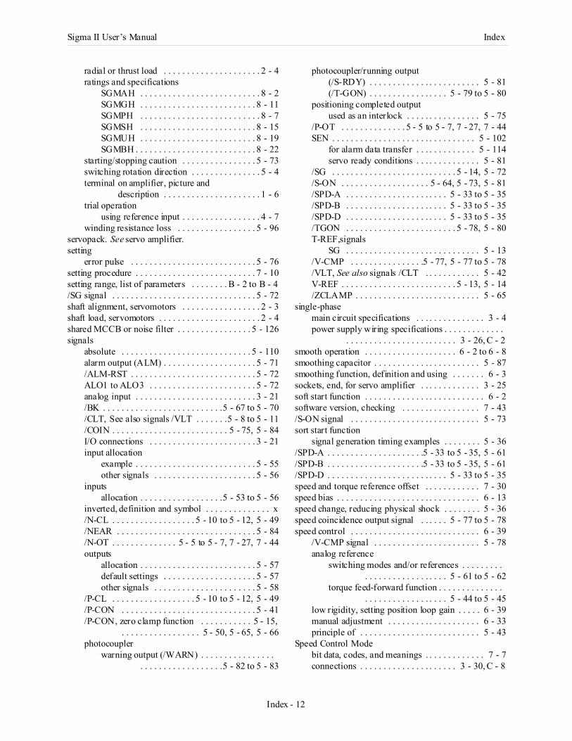
Sigma II User’s Manual Index
Index - 12
radial or thrust load . . . . . . . . . . . . . . . . . . . . . 2 - 4ratings and specifications
SGMAH . . . . . . . . . . . . . . . . . . . . . . . . . . 8 - 2SGMGH . . . . . . . . . . . . . . . . . . . . . . . . . 8 - 11SGMPH . . . . . . . . . . . . . . . . . . . . . . . . . . 8 - 7SGMSH . . . . . . . . . . . . . . . . . . . . . . . . . 8 - 15SGMUH . . . . . . . . . . . . . . . . . . . . . . . . . 8 - 19SGMBH . . . . . . . . . . . . . . . . . . . . . . . . . . 8 - 22
starting/stopping caution . . . . . . . . . . . . . . . . 5 - 73switching rotation direction . . . . . . . . . . . . . . . 5 - 4terminal on amplifier, picture and
description . . . . . . . . . . . . . . . . . . . . . 1 - 6trial operation
using reference input . . . . . . . . . . . . . . . . . 4 - 7winding resistance loss . . . . . . . . . . . . . . . . . 5 - 96
servopack. See servo amplifier.setting
error pulse . . . . . . . . . . . . . . . . . . . . . . . . . . . 5 - 76setting procedure . . . . . . . . . . . . . . . . . . . . . . . . . . 7 - 10setting range, list of parameters . . . . . . . . B - 2 to B - 4/SG signal . . . . . . . . . . . . . . . . . . . . . . . . . . . . . . . 5 - 72shaft alignment, servomotors . . . . . . . . . . . . . . . . . 2 - 3shaft load, servomotors . . . . . . . . . . . . . . . . . . . . . . 2 - 4shared MCCB or noise filter . . . . . . . . . . . . . . . . 5 - 126signals
absolute . . . . . . . . . . . . . . . . . . . . . . . . . . . . 5 - 110alarm output (ALM) . . . . . . . . . . . . . . . . . . . . 5 - 71/ALM-RST . . . . . . . . . . . . . . . . . . . . . . . . . . . 5 - 72ALO1 to ALO3 . . . . . . . . . . . . . . . . . . . . . . . 5 - 72analog input . . . . . . . . . . . . . . . . . . . . . . . . . . 3 - 21/BK . . . . . . . . . . . . . . . . . . . . . . . . . .5 - 67 to 5 - 70/CLT, See also signals /VLT . . . . . . .5 - 8 to 5 - 11/COIN . . . . . . . . . . . . . . . . . . . . . . . . . 5 - 75, 5 - 84I/O connections . . . . . . . . . . . . . . . . . . . . . . . 3 - 21input allocation
example . . . . . . . . . . . . . . . . . . . . . . . . . . 5 - 55other signals . . . . . . . . . . . . . . . . . . . . . . 5 - 56
inputsallocation . . . . . . . . . . . . . . . . . .5 - 53 to 5 - 56
inverted, definition and symbol . . . . . . . . . . . . . . x/N-CL . . . . . . . . . . . . . . . . . . 5 - 10 to 5 - 12, 5 - 49/NEAR . . . . . . . . . . . . . . . . . . . . . . . . . . . . . . 5 - 84/N-OT . . . . . . . . . . . . . . 5 - 5 to 5 - 7, 7 - 27, 7 - 44outputs
allocation . . . . . . . . . . . . . . . . . . . . . . . . . 5 - 57default settings . . . . . . . . . . . . . . . . . . . . 5 - 57other signals . . . . . . . . . . . . . . . . . . . . . . 5 - 58
/P-CL . . . . . . . . . . . . . . . . . . 5 - 10 to 5 - 12, 5 - 49/P-CON . . . . . . . . . . . . . . . . . . . . . . . . . . . . . 5 - 41/P-CON, zero clamp function . . . . . . . . . . . 5 - 15,
. . . . . . . . . . . . . . . . . 5 - 50, 5 - 65, 5 - 66photocoupler
warning output (/WARN) . . . . . . . . . . . . . . . . . . . . . . . . . . . . . . . . . .5 - 82 to 5 - 83
photocoupler/running output(/S-RDY) . . . . . . . . . . . . . . . . . . . . . . . . 5 - 81(/T-GON) . . . . . . . . . . . . . . . . . 5 - 79 to 5 - 80
positioning completed outputused as an interlock . . . . . . . . . . . . . . . . 5 - 75
/P-OT . . . . . . . . . . . . . . 5 - 5 to 5 - 7, 7 - 27, 7 - 44SEN . . . . . . . . . . . . . . . . . . . . . . . . . . . . . . . 5 - 102
for alarm data transfer . . . . . . . . . . . . . 5 - 114servo ready conditions . . . . . . . . . . . . . . 5 - 81
/SG . . . . . . . . . . . . . . . . . . . . . . . . . . . 5 - 14, 5 - 72/S-ON . . . . . . . . . . . . . . . . . . . 5 - 64, 5 - 73, 5 - 81/SPD-A . . . . . . . . . . . . . . . . . . . . . . 5 - 33 to 5 - 35/SPD-B . . . . . . . . . . . . . . . . . . . . . . 5 - 33 to 5 - 35/SPD-D . . . . . . . . . . . . . . . . . . . . . . 5 - 33 to 5 - 35/TGON . . . . . . . . . . . . . . . . . . . . . . . . 5 - 78, 5 - 80T-REF,signals
SG . . . . . . . . . . . . . . . . . . . . . . . . . . . . . 5 - 13/V-CMP . . . . . . . . . . . . . . . .5 - 77, 5 - 77 to 5 - 78/VLT, See also signals /CLT . . . . . . . . . . . . 5 - 42V-REF . . . . . . . . . . . . . . . . . . . . . . . . . 5 - 13, 5 - 14/ZCLAMP . . . . . . . . . . . . . . . . . . . . . . . . . . . 5 - 65
single-phasemain circuit specifications . . . . . . . . . . . . . . . 3 - 4power supply wiring specifications . . . . . . . . . . . . .
. . . . . . . . . . . . . . . . . . . . . . . . 3 - 26, C - 2smooth operation . . . . . . . . . . . . . . . . . . . . 6 - 2 to 6 - 8smoothing capacitor . . . . . . . . . . . . . . . . . . . . . . . 5 - 87smoothing function, definition and using . . . . . . . 6 - 3sockets, end, for servo amplifier . . . . . . . . . . . . . 3 - 25soft start function . . . . . . . . . . . . . . . . . . . . . . . . . . 6 - 2software version, checking . . . . . . . . . . . . . . . . . 7 - 43/S-ON signal . . . . . . . . . . . . . . . . . . . . . . . . . . . . 5 - 73sort start function
signal generation timing examples . . . . . . . . 5 - 36/SPD-A . . . . . . . . . . . . . . . . . . . . .5 - 33 to 5 - 35, 5 - 61/SPD-B . . . . . . . . . . . . . . . . . . . . .5 - 33 to 5 - 35, 5 - 61/SPD-D . . . . . . . . . . . . . . . . . . . . . . . . . . 5 - 33 to 5 - 35speed and torque reference offset . . . . . . . . . . . . 7 - 30speed bias . . . . . . . . . . . . . . . . . . . . . . . . . . . . . . . 6 - 13speed change, reducing physical shock . . . . . . . . 5 - 36speed coincidence output signal . . . . . . 5 - 77 to 5 - 78speed control . . . . . . . . . . . . . . . . . . . . . . . . . . . . 6 - 39
/V-CMP signal . . . . . . . . . . . . . . . . . . . . . . . 5 - 78analog reference
switching modes and/or references . . . . . . . . . . . . . . . . . . . . . . . . . . . 5 - 61 to 5 - 62
torque feed-forward function . . . . . . . . . . . . . . . . . . . . . . . . . . . . . . . . 5 - 44 to 5 - 45
low rigidity, setting position loop gain . . . . . 6 - 39manual adjustment . . . . . . . . . . . . . . . . . . . . 6 - 33principle of . . . . . . . . . . . . . . . . . . . . . . . . . . 5 - 43
Speed Control Modebit data, codes, and meanings . . . . . . . . . . . . . 7 - 7connections . . . . . . . . . . . . . . . . . . . . . 3 - 30, C - 8
Sigma II User’s Manual Index
Index - 13
description, analog reference . . . . . . . . . . . . . 5 - 60trial operation . . . . . . . . . . . . . . . . . . . . . . . . . . 4 - 7
speed feedback compensation . . . . . . . . . . 6 - 18, 6 - 31speed feedback compensation selection . . . . . . . . 6 - 29speed feed-forward function . . . . . . . . . .5 - 46 to 5 - 47
speed limitfunction, external . . . . . . . . . . . . . . . . . . . . . . 5 - 43principle . . . . . . . . . . . . . . . . . . . . . . . . . . . . . 5 - 43
speed loopgain parameter . . . . . . . . . . . . . . . . . . . . . . . . 6 - 30integral time constant . . . . . . . . . . . . . . . . . . . 6 - 35setting gain . . . . . . . . . . . . . . . . . . . . . . . . . . . 6 - 35
speed loop gain . . . . . . . . . . . . . . . 6 - 18, 6 - 20, 6 - 33adjustment conditions . . . . . . . . . . . . . . . . . . . 6 - 5adjustment, basic rules . . . . . . . . . . .6 - 31 to 6 - 32reference values . . . . . . . . . . . . . . . .6 - 38 to 6 - 39setting . . . . . . . . . . . . . . . . . . . . . . . . . . . . . . . . 6 - 9
speed loop integral time constant . . . . . . . 6 - 30, 6 - 33speed reference . . . . . . . . . . . . . . . 5 - 13, 6 - 12, 6 - 31
used as detection point . . . . . . . . . . . . . . . . . . 6 - 14input gain . . . . . . . . . . . . . . . . . . . . . . . . . . . . 6 - 34
speed reference inputinput circuit example/adjustment factor . . . . 5 - 14setting examples . . . . . . . . . . . . . . . . . . . . . . . 5 - 13
speed reference offsetautomatic adjustment . . . . . . . . . . . .7 - 30 to 7 - 32manual adjustment . . . . . . . . . . . . . .7 - 33 to 7 - 35
speed/torque curves. See servomotors/motor speed/torque characteristics.
S-Phase rotation signalsPCO . . . . . . . . . . . . . . . . . . . . . . . . . . . . . . . . 3 - 22/PCO . . . . . . . . . . . . . . . . . . . . . . . . . . . . . . . . 3 - 22
/S-RDY signal . . . . . . . . . . . . . . . . . . . . . . . . . . . . 5 - 81standard connection examples
Position Control Mode . . . . . . . . . . . . . 3 - 31, C - 7Speed Control Mode . . . . . . . . . . . . . . 3 - 32, C - 8Torque Control Mode . . . . . . . . . . . . . 3 - 33, C - 9
starting/stopping the servomotor, caution . . . . . . . 5 - 73Status Display Mode, digital operator . . . . . . . . . . . 7 - 7storage conditions, servo amplifiers . . . . . . . . . . . . 2 - 6sum check alarm. See check sum alarm.supply voltage
three-phase 400V . . . . . . . . . . . . . . . . . . . . . 5 - 129switches, default settings list . . . . . . . . . . . B - 5 to B - 8switching control modes and/or references . . . . . . . . . .
. . . . . . . . . . . . . . . . . . . . . . . . . .5 - 61 to 5 - 62switching noise . . . . . . . . . . . . . . . . . . . . . . . . . . 5 - 122Tterminals
CN1inverting signals, SO1 to SO3 . . . . . . . . 5 - 58selecting/allocating outputs . . . . . . . . . . . . . . .
. . . . . . . . . . . . . . . . . .5 - 57 to 5 - 59
CN2, layout and types . . . . . . . . . . . . . . . . . 3 - 25control power supply, picture and
description . . . . . . . . . . . . . . . . . . . . 1 - 6ground, picture and description . . . . . . . . . . . 1 - 6main circuit power supply, picture and
description . . . . . . . . . . . . . . . . . . . . 1 - 6servomotor to servo amplifier, picture and
description . . . . . . . . . . . . . . . . . . . . 1 - 6test run, see also trial operation . . . . . . . . 4 - 2 to 4 - 12/TGON signal . . . . . . . . . . . . . . . . . . . . . 5 - 79 to 5 - 80three-phase
main circuit specifications . . . . . . . . . . . 3 - 5, 3 - 6output phase forms . . . . . . . . . . . . . . . . . . . . 5 - 22power supply
wiring specifications (200V) . . . . 3 - 27, C - 3wiring specifications (400V) . . . . 3 - 28, C - 4wiring specifications (400V), large capacity . . . . . . . . . . . . . . . . . . . . . . . . . . 3 -29, C - 5
thrust load, servomotors . . . . . . . . . . . . . . . . . . . . . 2 - 4time constant
speed loop integral . . . . . . . . . . . . . . . . . . . . 6 - 30torque reference filter . . . . . . . . . . . . . . . . . . 6 - 30
time constant, integral . . . . . . . . . . . . . . . . . . . . . . 6 - 9timing
holding brake ON timing . . . . . . . . . . . . . . . 5 - 69torque control
description . . . . . . . . . . . . . . . . . . . . . . . . . . 5 - 42examples . . . . . . . . . . . . . . . . . . . . . . . . . . . . 5 - 38input circuit example . . . . . . . . . . . . . . . . . . 5 - 41internal speed limit function . . . . . . . . . . . . . 5 - 42parameter . . . . . . . . . . . . . . . . . . . . . . . . . . . 5 - 42selecting . . . . . . . . . . . . . . . . . . . . . . . . . . . . 5 - 37using . . . . . . . . . . . . . . . . . . . . . . . . . . . . . . . 5 - 37
torque control (analog reference)description . . . . . . . . . . . . . . . . . . . . . . . . . . 5 - 60
Torque Control Modeauto-tuning alert . . . . . . . . . . . . . . . . . . . . . . 6 - 21bit data, codes, and meanings . . . . . . . . . . . . . 7 - 7connections . . . . . . . . . . . . . . . . . . . . . 3 - 33, C - 9description, analog reference . . . . . . . . . . . . 5 - 60
torque feed-forward functionauto-tuning alert . . . . . . . . . . . . . . . . . . . . . . 6 - 21using, setting . . . . . . . . . . . . . . . . . . 5 - 44 to 5 - 45
torque limit . . . . . . . . . . . . . . . . . . . . . . . . . . . . . . . 5 - 8/CLT signal . . . . . . . . . . . . . . . . . . . . . . . . . . . 5 - 9external . . . . . . . . . . . . . . . . . . . . . . . . . . . . . 5 - 10
/N-CL . . . . . . . . . . . . . . . . . . . . . . . . . . . 5 - 12/P-CL . . . . . . . . . . . . . . . . . . . . . . . . . . . 5 - 12
internal, /CLT . . . . . . . . . . . . . . . . . . . . . . . . . 5 - 8torque limiting by analog reference . . . . 5 - 48 to 5 - 49torque reference
filter time constant . . . . . . . . . . . . . . . . . . . . . 6 - 7input . . . . . . . . . . . . . . . . . . . . . . . . . . . . . . . 5 - 40
used for proportional (P) control . . . . . . 6 - 15
Sigma II User’s Manual Index
Index - 14
torque reference (continued)input adjustment factor . . . . . . . . . . . . . . . . . 5 - 49used as reference point . . . . . . . . . . . . . . . . . . 6 - 14voltage level per rated torque . . . . . . . . . . . . . 5 - 40
torque reference filter time constant . . . . . . . . . . 6 - 30, . . . . . . . . . . . . . . . . . . . . . . . . . . . 6 - 34, 6 - 35
torque reference offsetautomatic adjustment . . . . . . . . . . . .7 - 30 to 7 - 32manual adjustment . . . . . . . . . . . . . .7 - 33 to 7 - 37
torque saturationmode switch function . . . . . . . . . . . . . . . . . . . 6 - 15
torsion resonance . . . . . . . . . . . . . . . . . . . . . . . . . . 6 - 34total Watts lost . . . . . . . . . . . . . . . . . . . . . . . . . . . 3 - 15traceback See Alarm Traceback Mode.transformer
DC reactor . . . . . . . . . . . . . . . . . . . . . . . . . . 5 - 132harmonic suppression . . . . . . . . . . . . . . . . . 5 - 131
transmission sequence, absolute encoders . . . . . . . . . . . . . . . . . . . . . . . . . . . . . . . . . . . . . . . . . . . 5 - 111
trial operation . . . . . . . . . . . . . . . . . . . . . .4 - 2 to 4 - 12additional setup procedures
position control by host controller . . . . . 4 - 11servomotors with brakes . . . . . . . . . . . . . 4 - 10
in Position Control Mode . . . . . . . . . . . . . . . . . 4 - 8in Speed Control Mode . . . . . . . . . . . . . . . . . . 4 - 7
trial operation (continued)input signals . . . . . . . . . . . . . . . . . . . . . . . . . . 4 - 12parameter requirements . . . . . . . . . . . . . . . . . 4 - 12servomotor with load . . . . . . . . . . . . . . . . . . . . 4 - 9servomotor without load . . . . . . . . . . . . . . . . . 4 - 3using reference input . . . . . . . . . . . . . . . . . . . . 4 - 7
troubleshootingwith alarm displays . . . . . . . . . . . . . . . . . . . . . 9 - 5with no alarm display . . . . . . . . . . . . . . . . . . . 9 - 39
two-step trial operation . . . . . . . . . . . . . . . .4 - 2 to 4 - 9Uundershoot
mode switch function . . . . . . . . . . . . . . . . . . . 6 - 15suppressing during positioning . . . . . . . . . . . 6 - 14
user constants. See parameters.V/V-CMP signal . . . . . . . . . . . . . . . . . . . .5 - 77 to 5 - 78vibration . . . . . . . . . . . . . . . . . . . . . . . . . . . . . . . . 6 - 19
excessive rigidity . . . . . . . . . . . . . . . . . . . . . . 6 - 23feedback loop principle . . . . . . . . . . . . . . . . . 6 - 31notch filter . . . . . . . . . . . . . . . . . . . . . . . . . . . . 6 - 8positioning time setting . . . . . . . . . . . . . . . . . 6 - 11servo amplifiers . . . . . . . . . . . . . . . . . . . . . . . . 2 - 8speed loop integral time constant . . . . . . . . . . 6 - 33
/VLT signal, see also /CLT signal . . . . . . . . . . . . 5 - 42voltage conversion transformer
capacity . . . . . . . . . . . . . . . . . . . . . . . . . . . . 5 - 129
W/WARN signal . . . . . . . . . . . . . . . . . . . . 5 - 82 to 5 - 83warning displays . . . . . . . . . . . . . . . . . . . . . . . . . 9 - 43warning output signal (/WARN) . . . . . . 5 - 82 to 5 - 83warning output signals . . . . . . . . . . . . . . . . . . . . . 9 - 43warnings
battery installation . . . . . . . . . . . . . . . . . . . 5 - 105ground terminals . . . . . . . . . . . . . . . . . . . . . 5 - 104Infinite Length Positioning System . . . . . . . . . . . . .
. . . . . . . . . . . . . . . . . . . . . . . . . . . 5 - 101maintenance and inspection . . . . . . . . . . . . . . . xiiimulti-turn limit . . . . . . . . . . . . . . . . . . . . . . 5 - 109wiring . . . . . . . . . . . . . . . . . . . . . . . . . . . . . . . . . .xi
winding resistance loss . . . . . . . . . . . . . . . . . . . . 5 - 94wiring
connection procedure . . . . . . . . . . . . . . . . . . 3 - 16example, main circuit . . . . . . . . . . . . . . . . . . 3 - 14fuse . . . . . . . . . . . . . . . . . . . . . . . . . . . . . . . 5 - 117isolation of inputs from outputs . . . . . . . . . 5 - 124using multiple servo amplifiers . . . . . . . . . 5 - 126noise control . . . . . . . . . . . . . . . . 5 - 115 to 5 - 126noise filters . . . . . . . . . . . . . . . . . 5 - 124 to 5 - 125precautions . . . . . . . . . . . . . . . . . . . . 3 - 12, 5 - 115servo amplifier to encoder . . . . . . . . . . . . . . 3 - 24specifications
Position Control Mode . . . . . . . . 3 - 31, C - 7single-phase power supply . . . . . . . . . . . . . . . .
. . . . . . . . . . . . . . . . . . . . 3 - 26, C - 2Speed Control Mode . . . . . . . . . . 3 - 32, C - 8three-phase power supply (200V) . . . . . . . . . .
. . . . . . . . . . . . . . . . . . . . 3 - 27, C - 3three-phase power supply (400V) . . . . . . . . . .
. . . . . . . . . . . . . . . . . . . . 3 - 28, C - 4large capacity (400V) . . . . . . . . . . 3 - 29, C - 5Torque Control Mode . . . . . . . . . . 3 - 33, C -9
warning . . . . . . . . . . . . . . . . . . . . . . . . . . . . . . . . .xiwrite protection . . . . . . . . . . . . . . . . . . . . . . . . . . 7 - 58YY-specification, checking codes . . . . . . 7 - 40 to 7 - 42Z/Z-CLAMP function . . . . . . . . . . . . . . . 5 - 65 to 5 - 66zero clamp function
/P-CON . . . . . . . . . . . . . . . . . . . . . . . . . . . . . 5 - 66switching with speed control (analog
reference) . . . . . . . . . . . . . . . . . . . . 5 - 62/Z-CLAMP . . . . . . . . . . . . . . . . . . . 5 - 65 to 5 - 66
zero point drift compensation . . . . . . . . . . . . . . . 7 - 49

YASKAWA ELECTRIC AMERICA, INC.Chicago-Corporate Headquarters 2121 Norman Drive South, Waukegan, IL 60085, U.S.A.Phone: (847) 887-7000 Fax: (847) 887-7310 Internet: http://www.yaskawa.comMOTOMAN INC.805 Liberty Lane, West Carrollton, OH 45449, U.S.A.Phone: (937) 847-6200 Fax: (937) 847-6277 Internet: http://www.motoman.comYASKAWA ELECTRIC CORPORATIONNew Pier Takeshiba South Tower, 1-16-1, Kaigan, Minatoku, Tokyo, 105-0022, JapanPhone: 81-3-5402-4511 Fax: 81-3-5402-4580 Internet: http ://www.yaskawa.co.jpYASKAWA ELETRICO DO BRASIL COMERCIO LTDA.Avenida Fagundes Filho, 620 Bairro Saude Sao Paolo-SP, Brasil CEP: 04304-000Phone: 55-11-5071-2552 Fax: 55-11-5581-8795 Internet: http://www.yaskawa.com.brYASKAWA ELECTRIC EUROPE GmbHAm Kronberger Hang 2, 65824 Schwalbach, GermanyPhone: 49-6196-569-300 Fax: 49-6196-888-301 Internet: http://www.yaskawa.deMOTOMAN ROBOTICS ABBox 504 S38525, Torsas, SwedenPhone: 46-486-48800 Fax: 46-486-41410MOTOMAN ROBOTEC GmbHKammerfeldstraβe 1, 85391 Allershausen, GermanyPhone: 49-8166-900 Fax: 49-8166-9039YASKAWA ELECTRIC UK LTD.1 Hunt Hill Orchardton Woods Cumbernauld, G68 9LF, Scotland, United KingdomPhone: 44-12-3673-5000 Fax: 44-12-3645-8182YASKAWA ELECTRIC KOREA CORPORATIONPaik Nam Bldg. 901 188-3, 1-Ga Euljiro, Joong-Gu, Seoul, KoreaPhone: 82-2-776-7844 Fax: 82-2-753-2639YASKAWA ELECTRIC (SINGAPORE) PTE. LTD.Head Office: 151 Lorong Chuan, #04-01, New Tech Park Singapore 556741, SINGAPOREPhone: 65-282-3003 Fax: 65-289-3003TAIPEI OFFICE (AND YATEC ENGINEERING CORPORATION)10F 146 Sung Chiang Road, Taipei, TaiwanPhone: 886-2-2563-0010 Fax: 886-2-2567-4677YASKAWA JASON (HK) COMPANY LIMITEDRm. 2909-10, Hong Kong Plaza, 186-191 Connaught Road West, Hong KongPhone: 852-2803-2385 Fax: 852-2547-5773BEIJING OFFICE Room No. 301 Office Building of Beijing International Club,21 Jianguomanwai Avenue, Beijing 100020, ChinaPhone: 86-10-6532-1850 Fax: 86-10-6532-1851SHANGHAI OFFICE 27 Hui He Road Shanghai 200437 ChinaPhone: 86-21-6553-6600 Fax: 86-21-6531-4242SHANGHAI YASKAWA-TONJI M & E CO., LTD.27 Hui He Road Shanghai 200437 ChinaPhone: 86-21-6533-2828 Fax: 86-21-6553-6677BEIJING YASKAWA BEIKE AUTOMATION ENGINEERING CO., LTD.30 Xue Yuan Road, Haidian, Beijing 100083 China Phone: 86-10-6232-9943 Fax: 86-10-6234-5002SHOUGANG MOTOMAN ROBOT CO., LTD.7, Yongchang-North Street, Beijing Economic & Technological Development Area,Beijing 100076 ChinaPhone: 86-10-6788-0551 Fax: 86-10-6788-2878YEA, TAICHUNG OFFICE IN TAIWAINB1, 6F, No.51, Section 2, Kung-Yi Road, Taichung City, Taiwan, R.O.C.Phone: 886-4-2320-2227 Fax:886-4-2320-2239
Yaskawa Electric America, Inc., February 2002 YEA-SIA-S800-32.2D Printed In U.S.A.