sierra clean energy
TRANSCRIPT

SIERRACLEANENERGYGUIDE
CLEANENERGY
Alternative Energy
The Promise of Geothermal PowerBringing New Efficiencies to Solar Photovoltaic ManufacturingGenerating Thermal Energy from the Sun
Research on Climate Change
Unlocking our Carbon History in Antarctic IceInvestigating the Impact of Ocean Acidification on Marine LifeReducing the Carbon Soot that Threatens Clean and Breathable Air
Green House Gas Emissions
Clean Coal Challenges in a Growing ChinaReducing the Cost of Engine Emissions TestingNew Green House Gas (GHG) Reporting Rule Affects a Wide Variety of IndustriesUsing Multipoint Systems to Measure Flare Gases for Green House Gas ReportingMaintaining Switchgears in Electricity Distribution and Reducing Environmental Impact
Biogas Fuels
Capturing Biogas from Landfills and Using it for CogenerationProducing Biogas from Solid Wastes and Using it for Cogeneration
Energy Conservation
District Heating Promises Lowest Carbon FootprintSmart Compressed Air Measurement Delivers Cost and Resource Savings
Water Treatment and Conservation
Optimizing Air Flows to Aeration Basins to Accelerate Clean Water ProductionNew Greenhouse Gas Rules Increase Use of Ozone in Water PurificationReducing the Costs of Rural Water Treatment and Increasing Conservation
4
10
16
26
30
34
C O N T E N T S

Think Ahead
It’s predicted that the clean energy industry will be the
third largest global industrial sector by 2020. Sierra is
passionately committed to supporting the visionaries
that will make that happen.
A global leader in flow measurement and control for
over 35 years, Sierra Instruments designs and manu-
factures high performance flow instrumentation for
gas, liquid and steam applications commonly found in the environmental, scientific
research, energy, semiconductor, petrochemical, aerospace, and general manufactur-
ing industries. With over 150 offices in 50 countries, Sierra is uniquely positioned to
provide our innovative products and lifetime support for the leading companies of
today and the growth enterprises of tomorrow.
Located amid the scenic beauty of the Monterey and Big Sur, California coastline,
Sierra has long demonstrated a deep appreciation for the environment and a
commitment to a sustainable future. As a part of that commitment, we have part-
nered with customers from all over the world to develop a host of solutions to some
of today’s most pressing environmental problems. From high performance flow
measurement instrumentation that helps create biofuel to unique measurement
solutions for environmental research on global warming, Sierra is pioneering the way.
This Sierra Clean Energy Guide introduces you to some of our most innovative
partners, and the unique solutions we have developed by Thinking Ahead...together.
You can find more information on Sierra, our product line and a wide range of
application stories at www.sierrainstruments.com/cleanenergy.
Matthew J. OlinPresident,Sierra Instruments
The
Big
SurC
oast
inM
onte
rey
Cou
nty,
Cal
iforn
ia,h
ome
toSi
erra
’sG
loba
lHea
dqua
rter
s
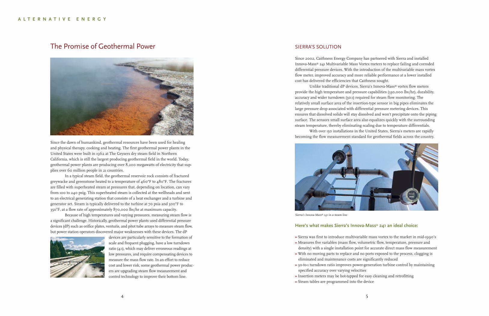
Sierra’s Innova-Mass® 241 in a steam line
5
Here’s what makes Sierra’s Innova-Mass® 241 an ideal choice:
» Sierra was first to introduce multivariable mass vortex to the market in mid-1990’s» Measures five variables (mass flow, volumetric flow, temperature, pressure anddensity) with a single installation point for accurate direct mass flow measurement
» With no moving parts to replace and no ports exposed to the process, clogging iseliminated and maintenance costs are significantly reduced
» 30-to-1 turndown ratio improves power-generation turbine control by maintainingspecified accuracy over varying velocities
» Insertion meters may be hot-tapped for easy cleaning and retrofitting» Steam tables are programmed into the device
The Promise of Geothermal Power
Since the dawn of humankind, geothermal resources have been used for healingand physical therapy, cooking and heating. The first geothermal power plants in theUnited States were built in 1962 at The Geysers dry steam field in NorthernCalifornia, which is still the largest producing geothermal field in the world. Today,geothermal power plants are producing over 8,200 megawatts of electricity that sup-plies over 60 million people in 21 countries.
In a typical steam field, the geothermal reservoir rock consists of fracturedgreywacke and greenstone heated to a temperature of 460°F to 480°F. The fracturesare filled with superheated steam at pressures that, depending on location, can varyfrom 100 to 240 psig. This superheated steam is collected at the wellheads and sentto an electrical generating station that consists of a heat exchanger and a turbine andgenerator set. Steam is typically delivered to the turbine at 70 psia and 300°F to350°F, at a flow rate of approximately 870,000 lbs/hr at maximum capacity.
Because of high temperatures and varying pressures, measuring steam flow isa significant challenge. Historically, geothermal power plants used differential pressuredevices (dP) such as orifice plates, venturis, and pitot tube arrays to measure steam flow,but power station operators discovered major weaknesses with these devices. The dP
devices are particularly sensitive to the formation ofscale and frequent plugging, have a low turndownratio (4:1), which may deliver erroneous readings atlow pressures, and require compensating devices tomeasure the mass flow rate. In an effort to reducecost and lower risk, some geothermal power produc-ers are upgrading steam flow measurement andcontrol technology to improve their bottom line.
A L T E R N A T I V E E N E R G Y
4
SIERRA’S SOLUTION
Since 2002, Caithness Energy Company has partnered with Sierra and installedInnova-Mass® 241 Multivariable Mass Vortex meters to replace failing and corrodeddifferential pressure devices. With the introduction of the multivariable mass vortexflow meter, improved accuracy and more reliable performance at a lower installedcost has delivered the efficiencies that Caithness sought.
Unlike traditional dP devices, Sierra’s Innova-Mass® vortex flow metersprovide the high temperature and pressure capabilities (330,000 lbs/hr), durability,accuracy and wider turndown (30:1) required for steam flow monitoring. Therelatively small surface area of the insertion-type sensor in big pipes eliminates thelarge pressure drop associated with differential pressure metering devices. Thisensures that dissolved solids will stay dissolved and won’t precipitate onto the pipingsurface. The sensors small surface area also equalizes quickly with the surroundingsteam temperature, thereby eliminating scaling due to temperature differentials.
With over 150 installations in the United States, Sierra’s meters are rapidlybecoming the flow measurement standard for geothermal fields across the country.
SIERRA’S SOLUTION
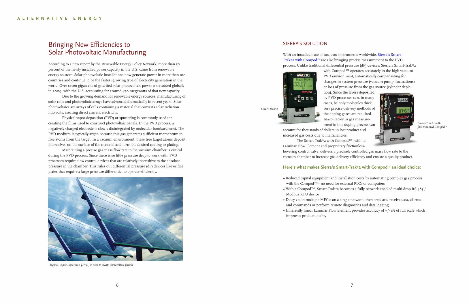
With an installed base of 100,000 instruments worldwide, Sierra’s Smart-Trak®2 with CompodTM are also bringing precise measurement to the PVD process.Unlike traditional differential pressure (dP) devices, Sierra's Smart-Trak®2
with Compod™ operates accurately in the high vacuumPVD environment, automatically compensating forchanges in system pressure (vacuum pump fluctuations)or loss of pressure from the gas source (cylinder deple-tion). Since the layers depositedby PVD processes can, in manycases, be only molecules thick,very precise delivery methods ofthe doping gases are required.Inaccuracies in gas measure-ment in this doping process can
account for thousands of dollars in lost product andincreased gas costs due to inefficiencies.
The Smart-Trak®2 with Compod™, with itsLaminar Flow Element and proprietary frictionless-hovering control valve, delivers a precisely controlled gas mass flow rate to thevacuum chamber to increase gas delivery efficiency and ensure a quality product.
Smart-Trak®2 withface-mounted CompodTM
7
Smart-Trak®2
Here’s what makes Sierra’s Smart-Trak®2 with CompodTM an ideal choice:
» Reduced capital equipment and installation costs by automating complex gas processwith the Compod™– no need for external PLCs or computers
» With a Compod™, Smart-Trak®2 becomes a fully network-enabled multi-drop RS-485 /Modbus RTU device
» Daisy-chain multiple MFC’s on a single network, then send and receive data, alarmsand commands or perform remote diagnostics and data logging
» Inherently linear Laminar Flow Element provides accuracy of +/- 1% of full scale whichimproves product quality
A L T E R N A T I V E E N E R G Y
Physical Vapor Deposition (PVD) is used to create photovoltaic panels
6
Bringing New Efficiencies toSolar Photovoltaic Manufacturing
According to a new report by the Renewable Energy Policy Network, more than 50percent of the newly installed power capacity in the U.S. came from renewableenergy sources. Solar photovoltaic installations now generate power in more than 100countries and continue to be the fastest-growing type of electricity generation in theworld. Over seven gigawatts of grid-tied solar photovoltaic power were added globallyin 2009, with the U.S. accounting for around 470 megawatts of that new capacity.
Due to the growing demand for renewable energy sources, manufacturing ofsolar cells and photovoltaic arrays have advanced dramatically in recent years. Solarphotovoltaics are arrays of cells containing a material that converts solar radiationinto volts, creating direct current electricity.
Physical vapor deposition (PVD) or sputtering is commonly used forcreating the films used to construct photovoltaic panels. In the PVD process, anegatively charged electrode is slowly disintegrated by molecular bombardment. ThePVD medium is typically argon because this gas generates sufficient momentum tofree atoms from the target. In a vacuum environment, these free target atoms depositthemselves on the surface of the material and form the desired coating or plating.
Maintaining a precise gas mass flow rate to the vacuum chamber is criticalduring the PVD process. Since there is so little pressure drop to work with, PVDprocesses require flow control devices that are relatively insensitive to the absolutepressure in the chamber. This rules out differential pressure (dP) devices like orificeplates that require a large pressure differential to operate efficiently.
SIERRA’S SOLUTION
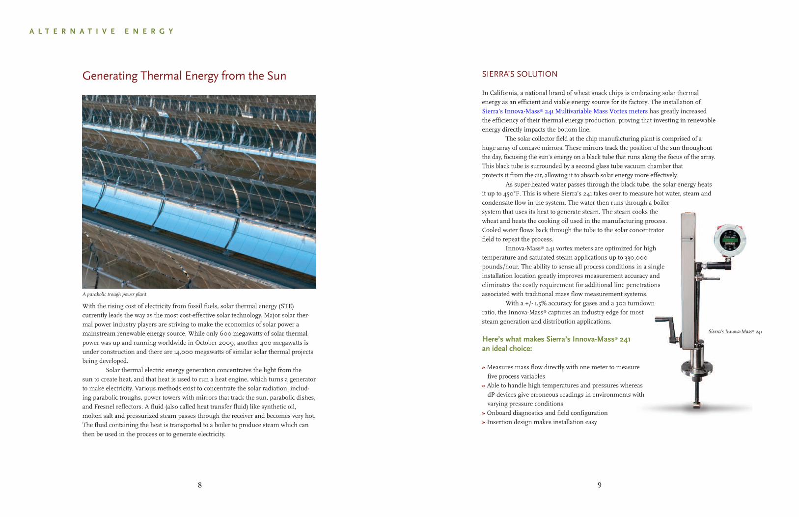
In California, a national brand of wheat snack chips is embracing solar thermal energy as an efficient and viable energy source for its factory. The installation of Sierra’s Innova-Mass® 241 Multivariable Mass Vortex meters has greatly increased the efficiency of their thermal energy production, proving that investing in renewable energy directly impacts the bottom line.
The solar collector field at the chip manufacturing plant is comprised of ahuge array of concave mirrors. These mirrors track the position of the sun throughoutthe day, focusing the sun’s energy on a black tube that runs along the focus of the array.This black tube is surrounded by a second glass tube vacuum chamber thatprotects it from the air, allowing it to absorb solar energy more effectively.
As super-heated water passes through the black tube, the solar energy heatsit up to 450°F. This is where Sierra’s 241 takes over to measure hot water, steam andcondensate flow in the system. The water then runs through a boilersystem that uses its heat to generate steam. The steam cooks thewheat and heats the cooking oil used in the manufacturing process.Cooled water flows back through the tube to the solar concentratorfield to repeat the process.
Innova-Mass® 241 vortex meters are optimized for hightemperature and saturated steam applications up to 330,000pounds/hour. The ability to sense all process conditions in a singleinstallation location greatly improves measurement accuracy andeliminates the costly requirement for additional line penetrationsassociated with traditional mass flow measurement systems.
With a +/- 1.5% accuracy for gases and a 30:1 turndownratio, the Innova-Mass® captures an industry edge for moststeam generation and distribution applications.
Here’s what makes Sierra’s Innova-Mass® 241an ideal choice:
» Measures mass flow directly with one meter to measurefive process variables
» Able to handle high temperatures and pressures whereasdP devices give erroneous readings in environments withvarying pressure conditions
» Onboard diagnostics and field configuration» Insertion design makes installation easy
9
Sierra’s Innova-Mass® 241
A L T E R N A T I V E E N E R G Y
Generating Thermal Energy from the Sun
With the rising cost of electricity from fossil fuels, solar thermal energy (STE)currently leads the way as the most cost-effective solar technology. Major solar ther-mal power industry players are striving to make the economics of solar power amainstream renewable energy source. While only 600 megawatts of solar thermalpower was up and running worldwide in October 2009, another 400 megawatts isunder construction and there are 14,000 megawatts of similar solar thermal projectsbeing developed.
Solar thermal electric energy generation concentrates the light from thesun to create heat, and that heat is used to run a heat engine, which turns a generatorto make electricity. Various methods exist to concentrate the solar radiation, includ-ing parabolic troughs, power towers with mirrors that track the sun, parabolic dishes,and Fresnel reflectors. A fluid (also called heat transfer fluid) like synthetic oil,molten salt and pressurized steam passes through the receiver and becomes very hot.The fluid containing the heat is transported to a boiler to produce steam which canthen be used in the process or to generate electricity.
A parabolic trough power plant
8
SIERRA’S SOLUTION
With just days left before Stanford researcher David Mucciarone was to leave forAntarctica, the mass flow controller in his carbon analyzer failed.
His instrumentation supplier recommended that he make the transition to Sierra. Heeding that advice, he purchased a Sierra Smart-Trak®2 Digital Mass Flow Controller just prior to boarding ship. He installed it on the trip down to Antarctica, and it worked...perfectly. But fierce trials lay ahead as the icebreaker Mucciarone was
travelling on plunged through hundreds of miles of thickice before delivering him to one of the most severe environ-ments on the planet.
Despite the challenges, the Smart-Trak®2 neverfaltered. “We’re very happy and that’s the bottom line,”says Mucciarone.
Based on his success with the carbon analyzer, he plans to employ additional analyzers on ocean reef and other ecosystems around the world—each containing a Sierra Smart-Trak®2 mass flow controller.
Here’s what makes Sierra’s Smart-Trak®2 an ideal choice:
» Patented, inherently linear Laminar Flow Element (LFE) design» Provides smooth and flexible valve performance» Pilot Module allows user to switch between ten pre-programmed gases, changesetpoint value and source, set zero, span and full scale, modify engineering units,choose output signal...and much more
» Has more robust electronics than other industry mass flow controllers
11
Smart-Trak®2
R E S E A R C H O N C L I M A T E C H A N G E
Unlocking our Carbon History in Antarctic Ice
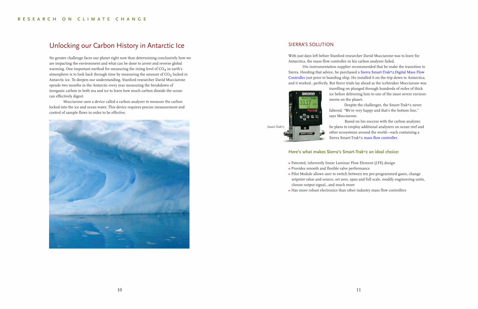
No greater challenge faces our planet right now than determining conclusively how weare impacting the environment and what can be done to arrest and reverse globalwarming. One important method for measuring the rising level of CO2 in earth’satmosphere is to look back through time by measuring the amount of CO2 locked inAntarctic ice. To deepen our understanding, Stanford researcher David Mucciaronespends two months in the Antarctic every year measuring the breakdown ofinorganic carbon in both sea and ice to learn how much carbon dioxide the oceancan effectively digest.
Mucciarone uses a device called a carbon analyzer to measure the carbonlocked into the ice and ocean water. This device requires precise measurement andcontrol of sample flows in order to be effective.
10
SIERRA’S SOLUTION
Intrigued by the Sierra Smark-Trak®2’s unique Pilot Module with Dial-a-Gas®
capabilities, Dr. Barry and his team made a switch to Sierra flow meters in 2005.With the stroke of a button on the Pilot Module, Dr. Barry was able to change his CO2,N2 and O2 flow rates instantly and remotely, creating many varieties of oceanicatmospheres in his tanks with the same set of conditions—same water, temperature,and animals.
Now he was able to simply plug his remote handheld Pilot Module into anyone of his nine Smart-Trak®2’s, makes a change in the gas flow rate (thus creatinganother atmosphere), and his new gas flow settings deliver at a rate that will notdeviate. If he wants to change his atmosphere again by entering new flow rates, ittakes only seconds.
“With the Smart-Trak®2,it couldn’t be easier––and faster,”says Barry. And this is whatscientists value most––time to concentrate on theirresearch work, rather thanadjusting instruments.
Sierra Smart-Trak®2 with remote Pilot Module
13
Here’s what makes Sierra’s Smart-Trak®2 an ideal choice:
» Control up to ten gases with a single instrument using the Dial-a-Gas® feature» Pilot Module allows full read/set of all variables in the field» Industry-leading powerful frictionless-hovering control valve for strengthand flexibility
» Highly accurate digital mass flow control
R E S E A R C H O N C L I M A T E C H A N G E
Investigating the Impact of Ocean Acidificationon Marine Life
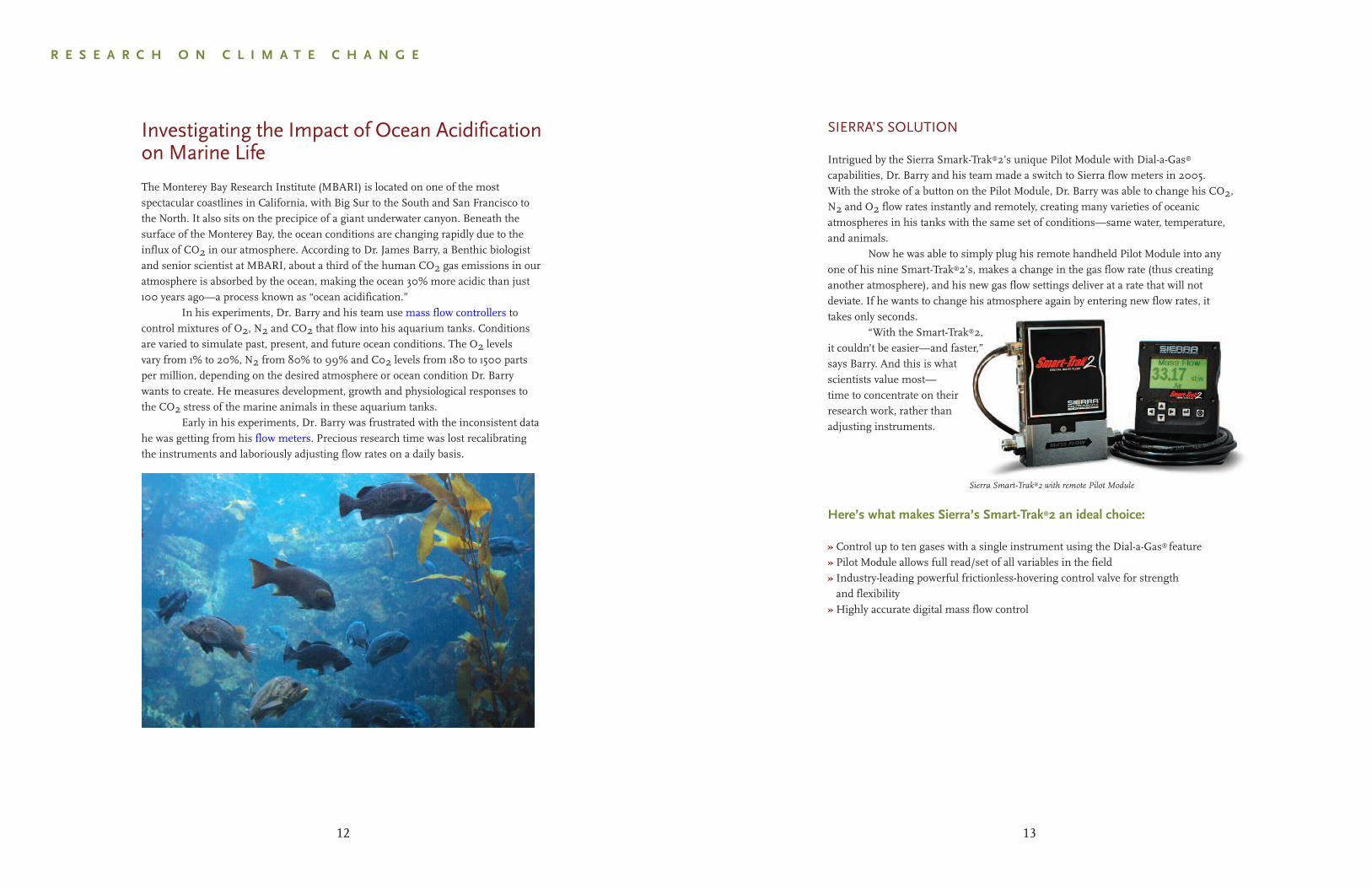
The Monterey Bay Research Institute (MBARI) is located on one of the mostspectacular coastlines in California, with Big Sur to the South and San Francisco tothe North. It also sits on the precipice of a giant underwater canyon. Beneath thesurface of the Monterey Bay, the ocean conditions are changing rapidly due to theinflux of CO2 in our atmosphere. According to Dr. James Barry, a Benthic biologistand senior scientist at MBARI, about a third of the human CO2 gas emissions in ouratmosphere is absorbed by the ocean, making the ocean 30% more acidic than just100 years ago—a process known as “ocean acidification.”
In his experiments, Dr. Barry and his team use mass flow controllers tocontrol mixtures of O2, N2 and CO2 that flow into his aquarium tanks. Conditionsare varied to simulate past, present, and future ocean conditions. The O2 levelsvary from 1% to 20%, N2 from 80% to 99% and C02 levels from 180 to 1500 partsper million, depending on the desired atmosphere or ocean condition Dr. Barrywants to create. He measures development, growth and physiological responses tothe CO2 stress of the marine animals in these aquarium tanks.
Early in his experiments, Dr. Barry was frustrated with the inconsistent data he was getting from his flow meters. Precious research time was lost recalibrating the instruments and laboriously adjusting flow rates on a daily basis.
12
Sierra’s Top-Trak®
15
R E S E A R C H O N C L I M A T E C H A N G E
Reducing the Carbon Soot that ThreatensClean and Breathable Air
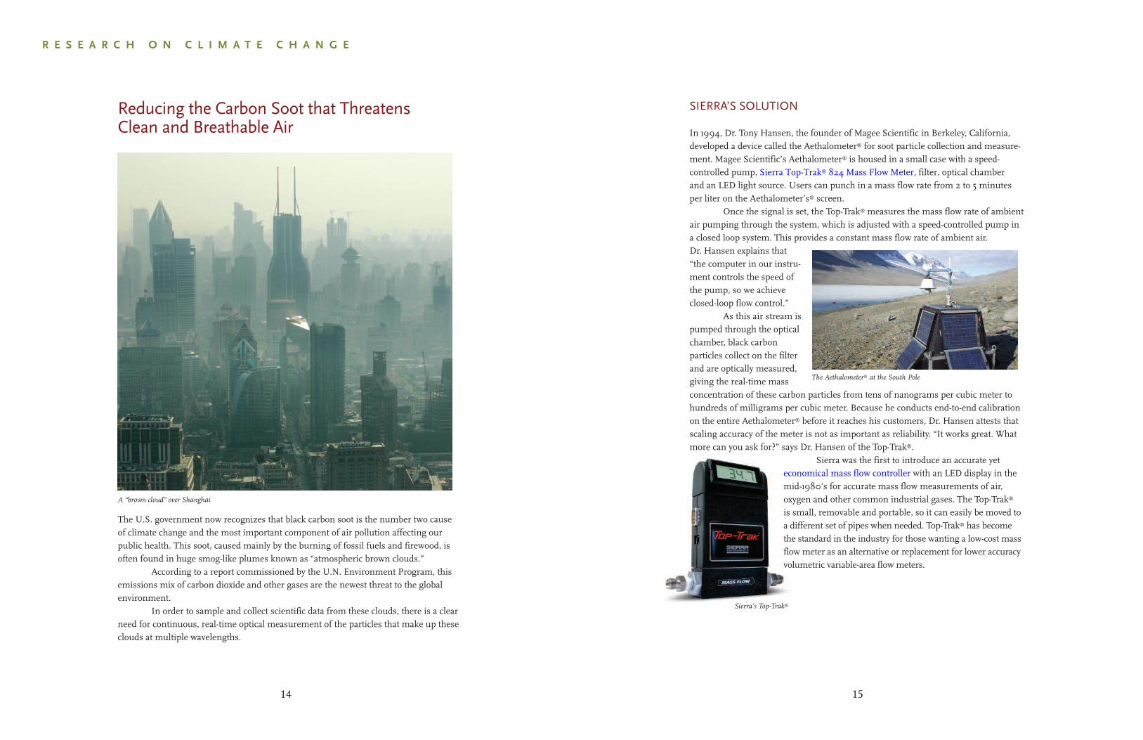
The U.S. government now recognizes that black carbon soot is the number two causeof climate change and the most important component of air pollution affecting ourpublic health. This soot, caused mainly by the burning of fossil fuels and firewood, isoften found in huge smog-like plumes known as “atmospheric brown clouds.”
According to a report commissioned by the U.N. Environment Program, thisemissions mix of carbon dioxide and other gases are the newest threat to the globalenvironment.
In order to sample and collect scientific data from these clouds, there is a clearneed for continuous, real-time optical measurement of the particles that make up theseclouds at multiple wavelengths.
A “brown cloud” over Shanghai
14
SIERRA’S SOLUTION
In 1994, Dr. Tony Hansen, the founder of Magee Scientific in Berkeley, California, developed a device called the Aethalometer® for soot particle collection and measure-ment. Magee Scientific’s Aethalometer® is housed in a small case with a speed-controlled pump, Sierra Top-Trak® 824 Mass Flow Meter, filter, optical chamber and an LED light source. Users can punch in a mass flow rate from 2 to 5 minutes per liter on the Aethalometer’s® screen.
Once the signal is set, the Top-Trak® measures the mass flow rate of ambientair pumping through the system, which is adjusted with a speed-controlled pump ina closed loop system. This provides a constant mass flow rate of ambient air.Dr. Hansen explains that“the computer in our instru-ment controls the speed ofthe pump, so we achieveclosed-loop flow control.”
As this air stream ispumped through the opticalchamber, black carbonparticles collect on the filterand are optically measured,giving the real-time massconcentration of these carbon particles from tens of nanograms per cubic meter tohundreds of milligrams per cubic meter. Because he conducts end-to-end calibrationon the entire Aethalometer® before it reaches his customers, Dr. Hansen attests thatscaling accuracy of the meter is not as important as reliability. “It works great. Whatmore can you ask for?” says Dr. Hansen of the Top-Trak®.
Sierra was the first to introduce an accurate yet economical mass flow controller with an LED display in the mid-1980’s for accurate mass flow measurements of air, oxygen and other common industrial gases. The Top-Trak®
is small, removable and portable, so it can easily be moved to a different set of pipes when needed. Top-Trak® has become the standard in the industry for those wanting a low-cost mass flow meter as an alternative or replacement for lower accuracy volumetric variable-area flow meters.
The Aethalometer® at the South Pole
SIERRA’S SOLUTION
The Hunan Electric Power DesignInstitute’s state-of-the-art coal-firedplant design for their 2008 YiyangCity installation provides a dramaticexample of how Sierra is helping fillthe demand for a cleaner process.
Building on the strengths of Yiyang I, built in 2001, Yiyang II required 16 high-precision mass flow meters for the measurement of combustion airflow to the boilers. After extensive testing of a wide variety of flow meters, the design engineers settled on Sierra’s Steel-Mass™ 640S meter. Almostimmediately upon installation,YiYang II demonstrated increased accuracy and the ability to operate reliably attemperatures as high as 400°C (750°F).
Accuracy is inherent in the Steel-Mass™ 640S sensor due to the use ofSierra’s proprietary Dry-Sense™ Sensor Technology, a swaging process to press thevelocity sensor into the thermowell. This creates a very stable sensor that does notrequire frequent calibration. Other thermal flow manufacturers use epoxies or glues tohold the sensing element in place, which can expand or contract over time creating“flow drift” that requires recalibration.
Sierra’s mass flow measurement solutions have significantly increasedefficiencies in the Chinese coal-fired sector, while reducing maintenance costs andemissions. In fact, the improvements in these areas have been so dramatic thatYiyang I is now scheduled to be retrofitted with Sierra instrumentation.
Here’s what makes the Sierra’s Steel-MassTM 640S an ideal choice:
» Measures mass flow directly with no temperature or pressure compensationrequired
» Operates at high temperatures in the range of 400°C (750°F)» Offers 100:1 turndown as compared to 4:1 turndown for traditional differentialpressure devices
» Single point insertion means low installation costs and easy retrofitting» Insertion meters may be hot-tapped for easy cleaning» With no holes to get clogged, it operates smoothly in dirty flows, unlike more
problematic averaging pitot tubes (annubars) and other differential pressure devices
17
Sierra meter measuring combustion air flow in duct
G R E E N H O U S E G A S E M I S S I O N S
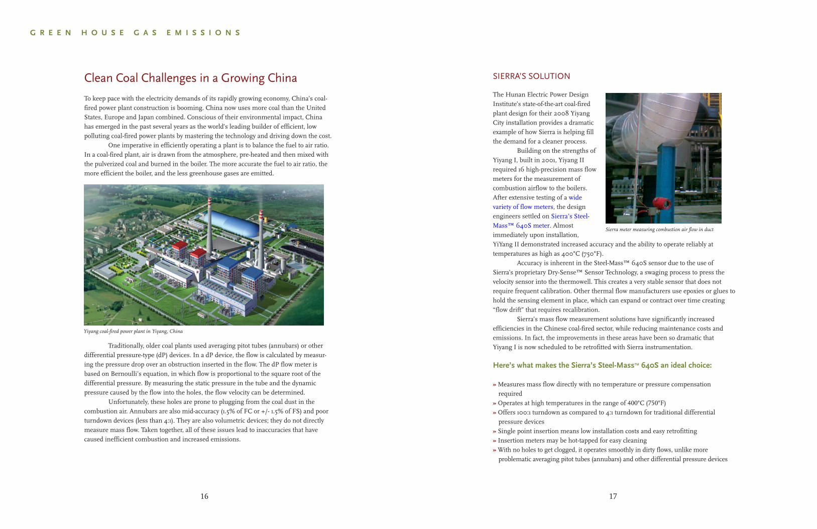
Clean Coal Challenges in a Growing China
To keep pace with the electricity demands of its rapidly growing economy, China’s coal-fired power plant construction is booming. China now uses more coal than the UnitedStates, Europe and Japan combined. Conscious of their environmental impact, Chinahas emerged in the past several years as the world’s leading builder of efficient, lowpolluting coal-fired power plants by mastering the technology and driving down the cost.
One imperative in efficiently operating a plant is to balance the fuel to air ratio.In a coal-fired plant, air is drawn from the atmosphere, pre-heated and then mixed withthe pulverized coal and burned in the boiler. The more accurate the fuel to air ratio, themore efficient the boiler, and the less greenhouse gases are emitted.
Traditionally, older coal plants used averaging pitot tubes (annubars) or otherdifferential pressure-type (dP) devices. In a dP device, the flow is calculated by measur-ing the pressure drop over an obstruction inserted in the flow. The dP flow meter isbased on Bernoulli’s equation, in which flow is proportional to the square root of thedifferential pressure. By measuring the static pressure in the tube and the dynamicpressure caused by the flow into the holes, the flow velocity can be determined.
Unfortunately, these holes are prone to plugging from the coal dust in thecombustion air. Annubars are also mid-accuracy (1.5% of FC or +/- 1.5% of FS) and poorturndown devices (less than 4:1). They are also volumetric devices; they do not directlymeasure mass flow. Taken together, all of these issues lead to inaccuracies that havecaused inefficient combustion and increased emissions.
16
Yiyang coal-fired power plant in Yiyang, China
SIERRA’S SOLUTION
Rob Graze, Senior Engineering Specialist at Caterpillar, contacted Sierra in 1991 with aproposition. Familiar with the successful relationship Sierra had forged with Caterpillar inthe 1980’s, Graze suggested a new exclusive instrument development partnership basedon his new patented Partial Flow Dilution Tunnel design. With a strong background inparticulate measurement and flow, Sierra saw great potential. Within twelve months, thenew BG®1, a highly efficient and accurate Partial Flow Sampling System (PFSS) no largerthan a household refrigerator, was testing non-road engines at Caterpillar for a fraction ofthe cost of traditional CVS systems.
Three years later, Sierra introduced the Model BG®2. Upgraded software greatly enhanced its ability to perform precise and accurate steady-state particulate meas-urements. In 2002, Sierra teamed with technology partners Caterpillar and CP Engineer-ing again to successfully develop the BG®3, a revolutionary PFSS advancement that was aimed towards tougher 2007 and Tier 4 emissions standards that mandated both steady state measurements for non-road engines and transient measurements for the much larger on-road diesel market.
MAKING HISTORYSufficiently impressed with both its accuracy and repeatability,
the United States EPA certified Sierra’s BG®3 in 2005 for use by Caterpillar in the certification and compliance of on-road engines to 2005 standards, thereby eliminating for the first time the need for expensive and cumbersome full-flow CVS systems.
The EPA worked exclusively over the last five years withSierra on a BG®3 vs CVS multiple engine correlation study in aneffort to get Partial Flow Dilution included in the Federal Registeras a legal alternative method to CVS in 40 CFR part 1065.On November 8, 2010 a Direct Final Rule enabling this to happen waspublished in the Federal Register.
The Direct Final Rule will become law on January 7, 2011and is considered to be an historic industry turning point by openingthe door to greater engine testing productivity to all Heavy Dutyas well as the Light Duty Vehicle manufacturers.
Here’s what makes Sierra’s BG®3 an ideal choice:
» A highly economical replacement for CVS systems; approximately 1/10th the cost» Annual electricity usage versus a CVS is approximately 1/20th the cost» Can be used on engines of any size and on any fuel, in both engine and chassis test cells» Portable from cell to cell» Zero-loss dilution tunnel» Satisfies all ISO 8178, ISO 16183, 40 CFR 1065 and CFR part 98 requirements» Ability to do simultaneous pre and post catalyst and/or diesel particulate filter research
19
Sierra BG®3
G R E E N H O U S E G A S E M I S S I O N S
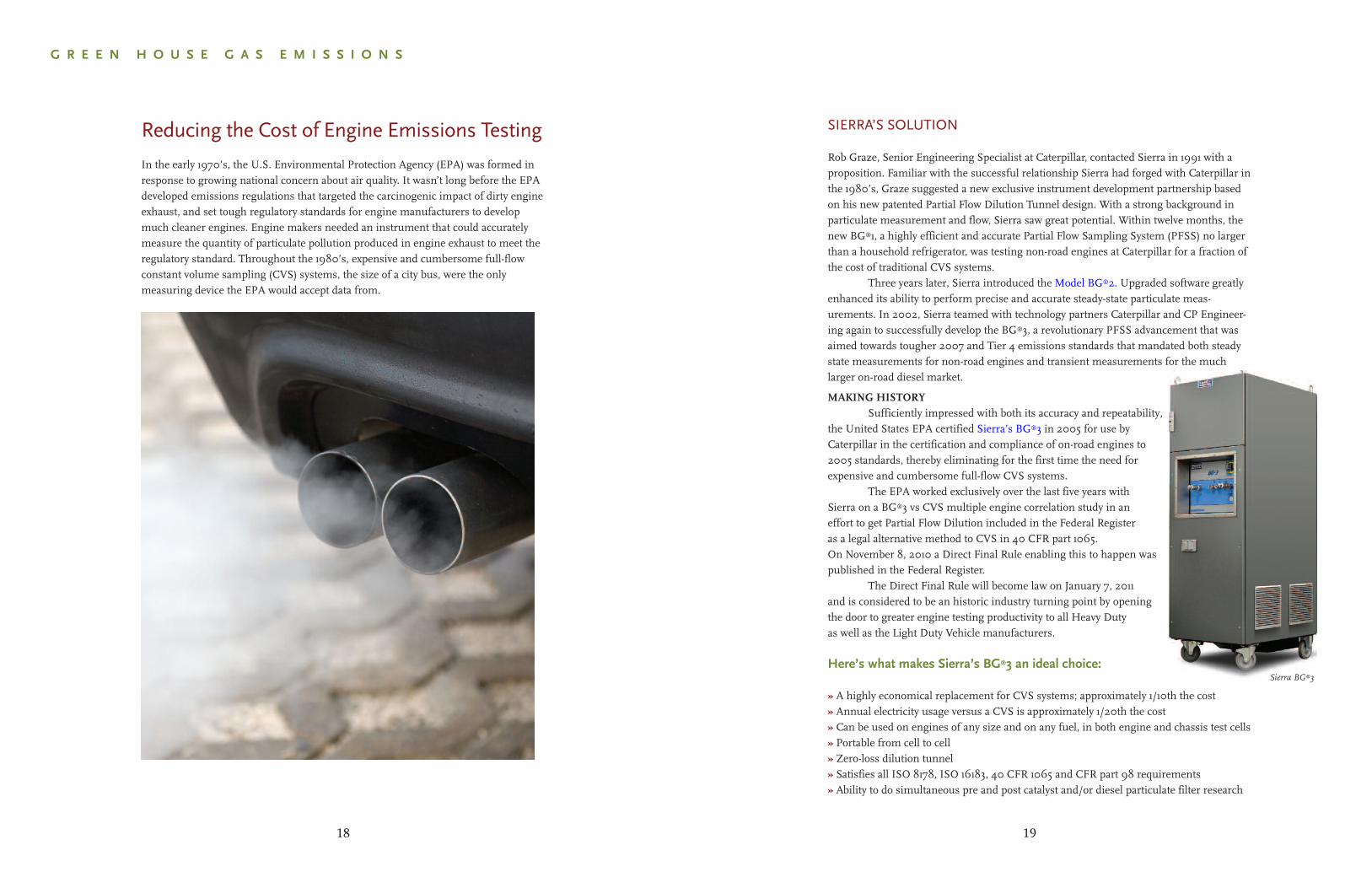
Reducing the Cost of Engine Emissions Testing
In the early 1970’s, the U.S. Environmental Protection Agency (EPA) was formed inresponse to growing national concern about air quality. It wasn’t long before the EPAdeveloped emissions regulations that targeted the carcinogenic impact of dirty engineexhaust, and set tough regulatory standards for engine manufacturers to developmuch cleaner engines. Engine makers needed an instrument that could accuratelymeasure the quantity of particulate pollution produced in engine exhaust to meet theregulatory standard. Throughout the 1980’s, expensive and cumbersome full-flowconstant volume sampling (CVS) systems, the size of a city bus, were the onlymeasuring device the EPA would accept data from.
18
SIERRA’S SOLUTION
To be prepared to support the needs of customers affected by GHG legislation, Sierrainitially developed the Boiler-Trak™ Mass Flow Meter in 2007 as a solution to
the California Global Warming Solutions Act of 2006. This is theprogram that the new EPA reporting mandate is modeled after. To date,Sierra has over 2,000 Boiler-Trak’s installed. It’s proven itself as anoptimal solution for measuring the fuel that is piped to gas-firedcombustion boilers, kilns and heaters.
Sierra has now self-certified several of their meters to meet therequirements of the new EPA rule. Look for the GHG certified logo through-
out Sierra's website to identify the GHG flow meters. In addition to new meters,Sierra can rapidly certify and recalibrate existing Sierra meters so that you canimmediately meet the new requirements.
Sierra also has a large installed base of flow devices for the measurement of landfill gases, the second largest source category in 40 CFR Part 98. Sierra’s Steel-Mass® 640S provides an optimal solution (see page 26-27 for more). In addition, Sierra routinely supplies their 640S and 780S series immersible thermal mass flow meters to the gas production and electrical generation sectors to measure the full list of greenhouse gases.
All Sierra meters referenced above have beenoptimized to meet 40 CFR part 98 and provide thefollowing benefits:
» Direct mass flow monitoring eliminates need for separatetemperature and pressure inputs
» Optimized for methane (CH4) as well as N20, SF6, HFCs,PFCs and CO2, per the EPA mandate
» 100:1 turndown accurately measures both low and high flows» Contains no moving parts which prevents clogging andlowers maintenance costs
» Minimal pressure drop and patented Dry-Sense™ SensorTechnology increases accuracy (+/- 1% of reading plus 0.5% of full scale)
» 640S & 780S are backed by a lifetime sensor warranty
Visit sierrainstruments.com/greenhouse.html and look for our GHG logo
21
G R E E N H O U S E G A S E M I S S I O N S
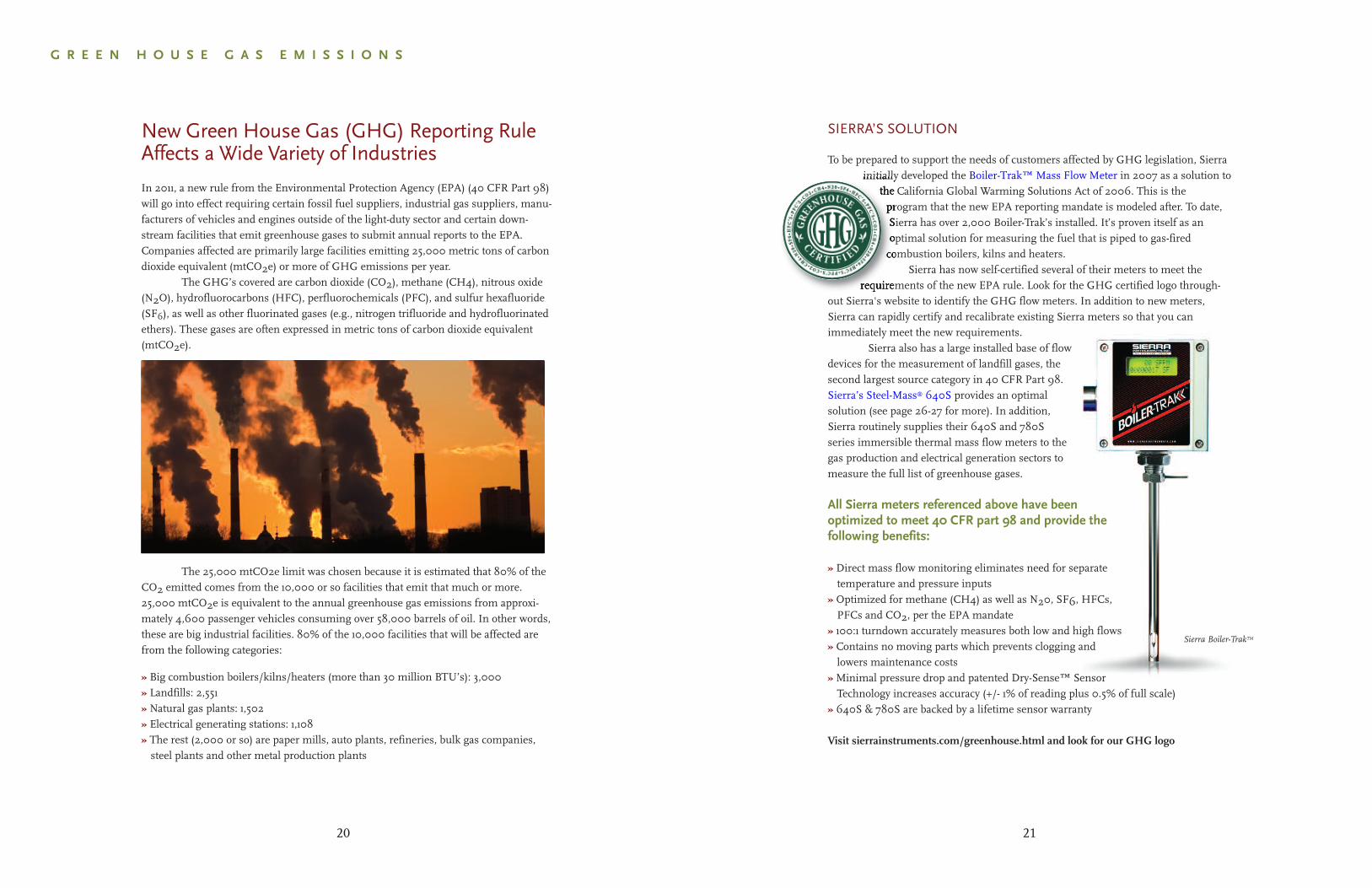
New Green House Gas (GHG) Reporting RuleAffects a Wide Variety of Industries
In 2011, a new rule from the Environmental Protection Agency (EPA) (40 CFR Part 98)will go into effect requiring certain fossil fuel suppliers, industrial gas suppliers, manu-facturers of vehicles and engines outside of the light-duty sector and certain down-stream facilities that emit greenhouse gases to submit annual reports to the EPA.Companies affected are primarily large facilities emitting 25,000 metric tons of carbondioxide equivalent (mtCO2e) or more of GHG emissions per year.
The GHG’s covered are carbon dioxide (CO2), methane (CH4), nitrous oxide(N2O), hydrofluorocarbons (HFC), perfluorochemicals (PFC), and sulfur hexafluoride(SF6), as well as other fluorinated gases (e.g., nitrogen trifluoride and hydrofluorinatedethers). These gases are often expressed in metric tons of carbon dioxide equivalent(mtCO2e).
The 25,000 mtCO2e limit was chosen because it is estimated that 80% of theCO2 emitted comes from the 10,000 or so facilities that emit that much or more.25,000 mtCO2e is equivalent to the annual greenhouse gas emissions from approxi-mately 4,600 passenger vehicles consuming over 58,000 barrels of oil. In other words,these are big industrial facilities. 80% of the 10,000 facilities that will be affected arefrom the following categories:
» Big combustion boilers/kilns/heaters (more than 30 million BTU’s): 3,000» Landfills: 2,551» Natural gas plants: 1,502» Electrical generating stations: 1,108» The rest (2,000 or so) are paper mills, auto plants, refineries, bulk gas companies,steel plants and other metal production plants
20
Sierra Boiler-TrakTM
Using Multipoint Systems to Measure FlareGases for Green House Gas Reporting
The World Bank estimates that over 150 billion cubic meters of natural gas are flaredor vented annually, an amount worth approximately 30 billion dollars. And tencountries account for 75% of the flare gas emissions. To reduce these emissions, thenew 2011 Environmental Protection Agency (EPA) rule (40 CFR Part 98) requirescompanies like landfills, refineries, and water treatment plants to report annual flaregas emissions to the EPA. (See page 20 for more.)
To mitigate greenhouse gas emissions, many of these companies reuse theirbiogas for cogeneration, but the amount of biogas produced often exceeds the amountneeded for cogeneration. In such cases, it is often not economical to purify, compressand store the gas for later use, so it is flared off. Accurate mass flow instrumentation isessential for these companies to comply with the new EPA requirements.
Measuring the mass flow of flare gases presents several challenges:
» Depending upon the process, the flare itself may be in a large diameter stack orduct with distorted or swirling flow profiles, making it difficult for mass flowinstrument to get an accurate reading
» Flows may be very low to very high depending upon the time of day, which makesdifferential pressure (dP) devices inaccurate because of their poor turndown (4:1)
» Flows may be dirty, wet, hot gases of mixed compositions which plug the holes indP devices like annubars, thereby increasing cost-of-ownership
» Stack piping may be difficult to access
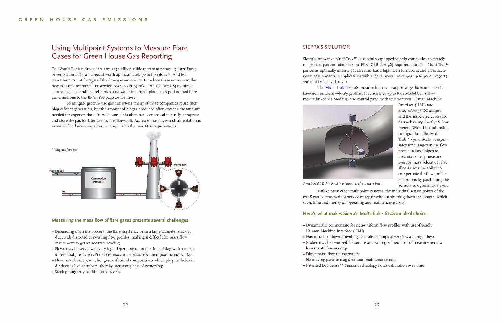
Multipoint flare gas
SIERRA’S SOLUTION
Sierra’s innovative Multi-Trak™ is specially equipped to help companies accuratelyreport flare gas emissions for the EPA (CFR Part 98) requirements. The Multi-Trak™performs optimally in dirty gas streams, has a high 100:1 turndown, and gives accu-rate measurements in applications with wide temperature ranges up to 400°C (750°F)and rapid velocity changes.
The Multi-Trak™ 670S provides high accuracy in large ducts or stacks that have non-uniform velocity profiles. It consists of up to four Model 640S flow meters linked via Modbus, one control panel with touch-screen Human Machine
Interface (HMI) and4-20mA/0-5VDC output,and the associated cables fordaisy-chaining the 640S flowmeters. With this multipointconfiguration, the Multi-Trak™ dynamically compen-sates for changes in the flowprofile in large pipes toinstantaneously measureaverage mass velocity. It alsoallows users the ability tocompensate for flow profiledistortions by positioning thesensors in optimal locations.
Unlike most other multipoint systems, the individual sensor points of the670S can be removed for service or repair without shutting down the system, whichsaves time and money on operating and maintenance costs.
Here’s what makes Sierra’s Multi-TrakTM 670S an ideal choice:
» Dynamically compensate for non-uniform flow profiles with user-friendlyHuman Machine Interface (HMI)
» Has 100:1 turndown providing accurate readings at very low and high flows» Probes may be removed for service or cleaning without loss of measurement tolower cost-of-ownership
» Direct mass flow measurement» No moving parts to clog decreases maintenance costs» Patented Dry-Sense™ Sensor Technology holds calibration over time
23
G R E E N H O U S E G A S E M I S S I O N S
22
Sierra’s Multi-TrakTM 670S in a large duct after a sharp bend
SIERRA’S SOLUTION
Responding to this challenge, Sierra workedin partnership with Energy MaintenanceTechnologies (EMT), in Luton, England, theleading supplier of predictive maintenancetest solutions for the utilities industry todevelop a comprehensive solution. The result-ing EMT Assero SF6MFU is a portable, fully-automated SF6 top-off and fill operation system.
This device is the size of a smallsuitcase, battery operated, and has many alarmoptions. Data logging includes SF6 used and endpressure stored on a CF card for traceability. Datacan be sent to a website via a General Packet Radio Service modem.
The key to the SF6MFU’s performance is an accurate mass flow controller to regulate the SF6 entering the vessels. Every SF6MFU includes a Sierra Smart-Trak®2 mass flow controller, a pressure transmitter, a battery monitor and guarding system,
overshoot pressure protection, a data logger with CF cardand/or GPRS modem. These are all controlled by Sierra’sHMI touch screen management system. All internal commu-nication takes place over a Modbus network which eliminatesdrift and transfers all information quickly and reliably.
In the utilities sector, the EMT Assero SF6MFUhas proven to reduce labor costs by fully-automating theSF6 top-off and fill process and help utility companiescomply with the strict greenhouse gas regulations of theKyoto Protocol.
Here’s what makes Sierra’s Smart-Trak®2 an ideal choice:
» OEM workhorse with its excellent performance results from a patented, inherentlylinear Laminar Flow Element (LFE)
» Fast control of gas mass flow over a wide range of temperature and pressure withdirect-acting control/shut-off valve
» Has more robust electronics to control a wide range of functions» Dial-A-Gas® technology for true digital performance for up to ten pre-programmedgases in one unit (gas type list can be programmed on request)
EMT Assero SF6MFU with Smart-Trak®2
Sierra’s Smart-Trak®2
25
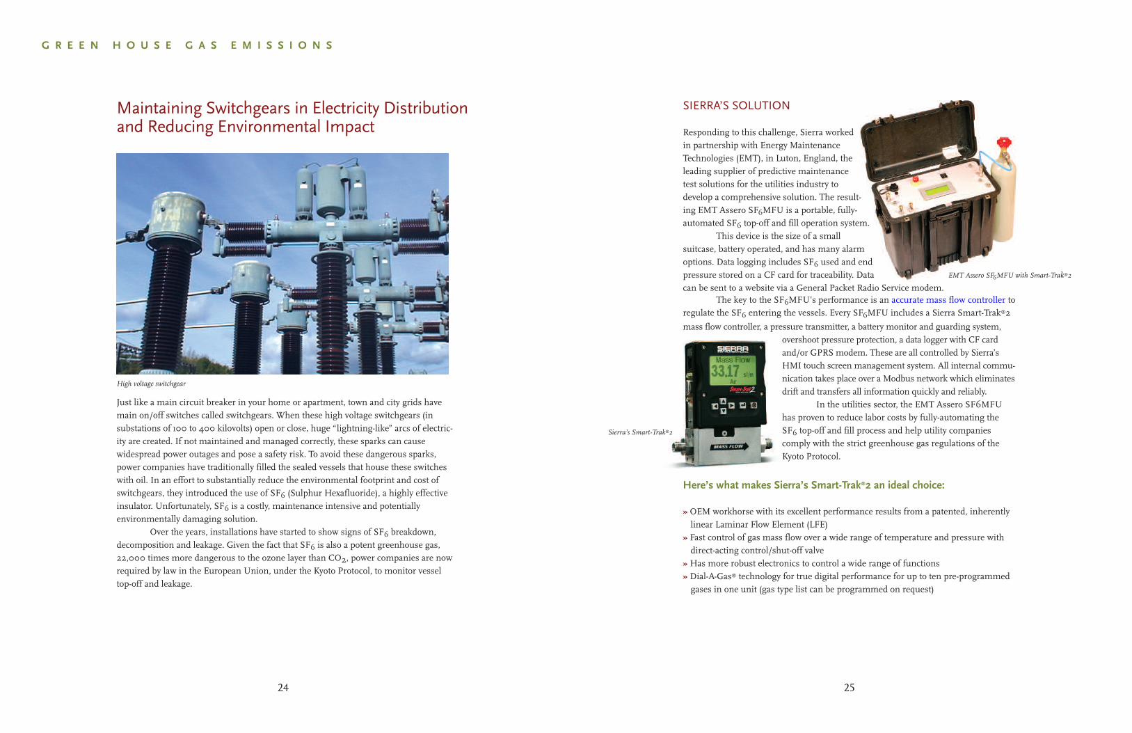
Maintaining Switchgears in Electricity Distributionand Reducing Environmental Impact
High voltage switchgear
G R E E N H O U S E G A S E M I S S I O N S
24
Just like a main circuit breaker in your home or apartment, town and city grids havemain on/off switches called switchgears. When these high voltage switchgears (insubstations of 100 to 400 kilovolts) open or close, huge “lightning-like” arcs of electric-ity are created. If not maintained and managed correctly, these sparks can causewidespread power outages and pose a safety risk. To avoid these dangerous sparks,power companies have traditionally filled the sealed vessels that house these switcheswith oil. In an effort to substantially reduce the environmental footprint and cost ofswitchgears, they introduced the use of SF6 (Sulphur Hexafluoride), a highly effectiveinsulator. Unfortunately, SF6 is a costly, maintenance intensive and potentiallyenvironmentally damaging solution.
Over the years, installations have started to show signs of SF6 breakdown,decomposition and leakage. Given the fact that SF6 is also a potent greenhouse gas,22,000 times more dangerous to the ozone layer than CO2, power companies are nowrequired by law in the European Union, under the Kyoto Protocol, to monitor vesseltop-off and leakage.
SIERRA’S SOLUTION
With an installed base of over 40,000instruments, Sierra’s Steel-Mass™ 640Sis helping companies accurately measurebiogas for EPA reporting and controlgas blending for cogeneration. Theinsertion design eliminates pressuredrop, has no moving parts, and canmeasure both high and low flows with a100:1 turndown.
With no moving parts to clogwith dirty, particulate laden gas and aself-cleaning purge option for dirty flowenvironments, the Steel-Mass™ 640Smaintains accuracy and lowers mainte-nance costs. The Steel-Mass™ sensorautomatically corrects for changes in gastemperature and pressure, eliminatingthe need for separate temperature andpressure transducers.
Sierra’s Steel-Mass™ 640S is the flagship of North America’s best-selling (1) thermal mass flow meters.(1) 2009 Flow Research Study, Yoder
Sierra Steel-MassTM 640S inserted into landfill flare
Here’s what makes Sierra’s Steel-MassTM640S an ideal choice:
» Optimized for methane (CH4) as well as N20, SF6, HFCs, PFCs and CO2,per the EPA mandate
» Generates nominal pressure drop across the immersible sensor probe» Measures mass flow directly with one instrument» Has a 100:1 turndown to measure low and high flows» Self-cleaning purge option for dirty flow environments» Easy, hot tap installation with a low cost-of-ownership» Backed by a lifetime sensor warranty and proprietary Dry-Sense™ Sensor Technology
27
B I O G A S F U E L S
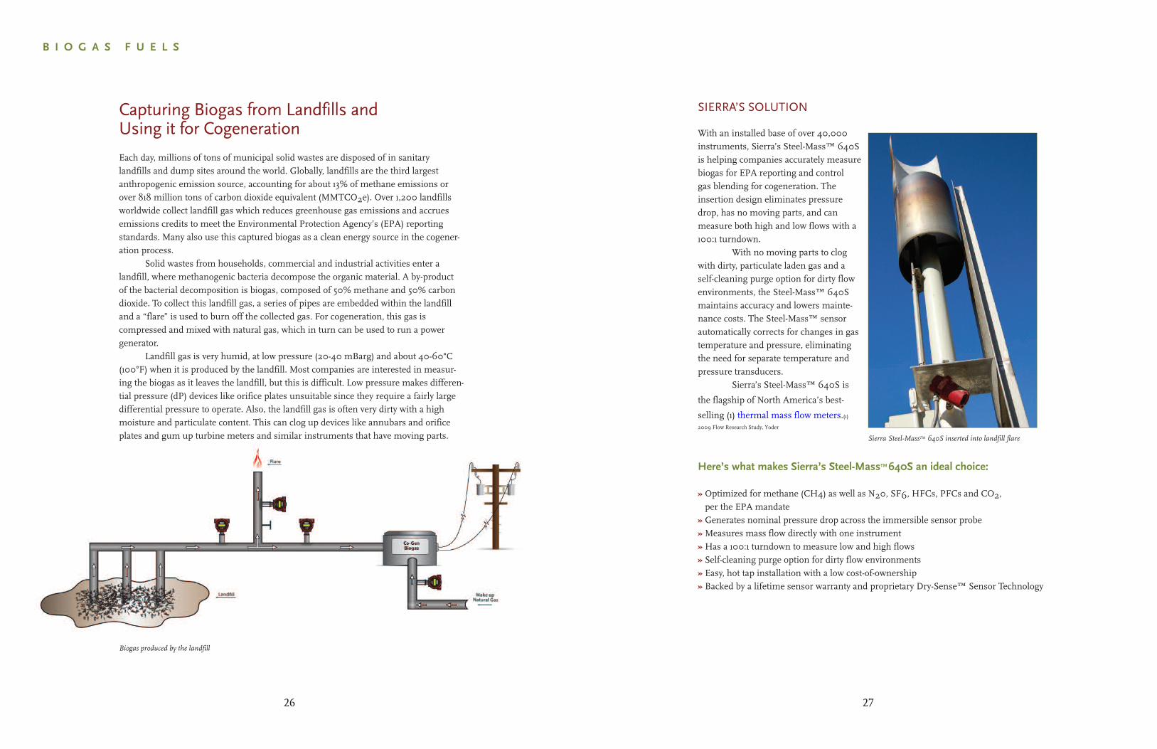
Capturing Biogas from Landfills andUsing it for Cogeneration
Each day, millions of tons of municipal solid wastes are disposed of in sanitarylandfills and dump sites around the world. Globally, landfills are the third largestanthropogenic emission source, accounting for about 13% of methane emissions orover 818 million tons of carbon dioxide equivalent (MMTCO2e). Over 1,200 landfillsworldwide collect landfill gas which reduces greenhouse gas emissions and accruesemissions credits to meet the Environmental Protection Agency’s (EPA) reportingstandards. Many also use this captured biogas as a clean energy source in the cogener-ation process.
Solid wastes from households, commercial and industrial activities enter alandfill, where methanogenic bacteria decompose the organic material. A by-productof the bacterial decomposition is biogas, composed of 50% methane and 50% carbondioxide. To collect this landfill gas, a series of pipes are embedded within the landfilland a “flare” is used to burn off the collected gas. For cogeneration, this gas iscompressed and mixed with natural gas, which in turn can be used to run a powergenerator.
Landfill gas is very humid, at low pressure (20-40 mBarg) and about 40-60°C(100°F) when it is produced by the landfill. Most companies are interested in measur-ing the biogas as it leaves the landfill, but this is difficult. Low pressure makes differen-tial pressure (dP) devices like orifice plates unsuitable since they require a fairly largedifferential pressure to operate. Also, the landfill gas is often very dirty with a highmoisture and particulate content. This can clog up devices like annubars and orificeplates and gum up turbine meters and similar instruments that have moving parts.
Biogas produced by the landfill
26
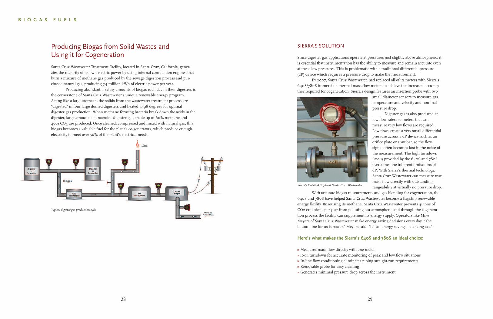
SIERRA’S SOLUTION
Since digester gas applications operate at pressures just slightly above atmospheric, itis essential that instrumentation has the ability to measure and remain accurate evenat these low pressures. This is problematic with a traditional differential pressure(dP) device which requires a pressure drop to make the measurement.
By 2007, Santa Cruz Wastewater, had replaced all of its meters with Sierra’s640S/780S immersible thermal mass flow meters to achieve the increased accuracythey required for cogeneration. Sierra’s design features an insertion probe with two
small diameter sensors to measure gastemperature and velocity and nominalpressure drop.
Digester gas is also produced atlow flow rates, so meters that canmeasure very low flows are required.Low flows create a very small differentialpressure across a dP device such as anorifice plate or annubar, so the flowsignal often becomes lost in the noise ofthe measurement. The high turndown(100:1) provided by the 640S and 780Sovercomes the inherent limitations ofdP. With Sierra’s thermal technology,Santa Cruz Wastewater can measure truemass flow directly with outstandingrangeability at virtually no pressure drop.
With accurate biogas measurements and gas blending for cogeneration, the640S and 780S have helped Santa Cruz Wastewater become a flagship renewableenergy facility. By reusing its methane, Santa Cruz Wastewater prevents 41 tons ofCO2 emissions per year from polluting our atmosphere, and through the cogenera-tion process the facility can supplement its energy supply. Operators like MikeMeyers of Santa Cruz Wastewater make energy saving decisions every day. “Thebottom line for us is power,” Meyers said. “It’s an energy savings balancing act.”
Sierra’s Flat-TrakTM 780 at Santa Cruz Wastewater
Here’s what makes the Sierra’s 640S and 780S an ideal choice:
» Measures mass flow directly with one meter» 100:1 turndown for accurate monitoring of peak and low flow situations» In-line flow conditioning eliminates piping straight-run requirements» Removable probe for easy cleaning» Generates minimal pressure drop across the instrument
29
Producing Biogas from Solid Wastes andUsing it for Cogeneration
Santa Cruz Wastewater Treatment Facility, located in Santa Cruz, California, gener-ates the majority of its own electric power by using internal combustion engines thatburn a mixture of methane gas produced by the sewage digestion process and pur-chased natural gas, producing 7.4 million kWh of electric power per year.
Producing abundant, healthy amounts of biogas each day in their digesters isthe cornerstone of Santa Cruz Wastewater’s unique renewable energy program.Acting like a large stomach, the solids from the wastewater treatment process are“digested” in four large domed digesters and heated to 98 degrees for optimaldigester gas production. When methane forming bacteria break down the acids in thedigester, large amounts of anaerobic digester gas, made up of 60% methane and40% CO2 are produced. Once cleaned, compressed and mixed with natural gas, thisbiogas becomes a valuable fuel for the plant’s co-generators, which produce enoughelectricity to meet over 50% of the plant’s electrical needs.
B I O G A S F U E L S
Typical digester gas production cycle
28
SIERRA’S SOLUTION
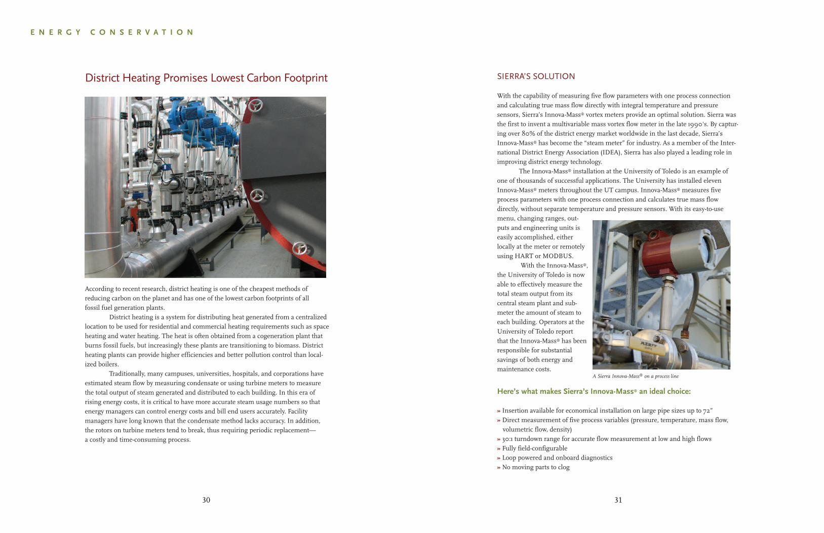
With the capability of measuring five flow parameters with one process connectionand calculating true mass flow directly with integral temperature and pressuresensors, Sierra’s Innova-Mass® vortex meters provide an optimal solution. Sierra wasthe first to invent a multivariable mass vortex flow meter in the late 1990's. By captur-ing over 80% of the district energy market worldwide in the last decade, Sierra’sInnova-Mass® has become the “steam meter” for industry. As a member of the Inter-national District Energy Association (IDEA), Sierra has also played a leading role inimproving district energy technology.
The Innova-Mass® installation at the University of Toledo is an example ofone of thousands of successful applications. The University has installed elevenInnova-Mass® meters throughout the UT campus. Innova-Mass® measures fiveprocess parameters with one process connection and calculates true mass flowdirectly, without separate temperature and pressure sensors. With its easy-to-usemenu, changing ranges, out-puts and engineering units iseasily accomplished, eitherlocally at the meter or remotelyusing HART or MODBUS.
With the Innova-Mass®,the University of Toledo is nowable to effectively measure thetotal steam output from itscentral steam plant and sub-meter the amount of steam toeach building. Operators at theUniversity of Toledo reportthat the Innova-Mass® has beenresponsible for substantialsavings of both energy andmaintenance costs.
Here’s what makes Sierra’s Innova-Mass® an ideal choice:
» Insertion available for economical installation on large pipe sizes up to 72”» Direct measurement of five process variables (pressure, temperature, mass flow,volumetric flow, density)
» 30:1 turndown range for accurate flow measurement at low and high flows» Fully field-configurable» Loop powered and onboard diagnostics» No moving parts to clog
A Sierra Innova-Mass® on a process line
31
E N E R G Y C O N S E R V A T I O N
District Heating Promises Lowest Carbon Footprint
According to recent research, district heating is one of the cheapest methods ofreducing carbon on the planet and has one of the lowest carbon footprints of allfossil fuel generation plants.
District heating is a system for distributing heat generated from a centralizedlocation to be used for residential and commercial heating requirements such as spaceheating and water heating. The heat is often obtained from a cogeneration plant thatburns fossil fuels, but increasingly these plants are transitioning to biomass. Districtheating plants can provide higher efficiencies and better pollution control than local-ized boilers.
Traditionally, many campuses, universities, hospitals, and corporations haveestimated steam flow by measuring condensate or using turbine meters to measurethe total output of steam generated and distributed to each building. In this era ofrising energy costs, it is critical to have more accurate steam usage numbers so thatenergy managers can control energy costs and bill end users accurately. Facilitymanagers have long known that the condensate method lacks accuracy. In addition,the rotors on turbine meters tend to break, thus requiring periodic replacement—a costly and time-consuming process.
30
Smart Compressed Air Measurement DeliversCost and Resource Savings
Air may be free, but compressed air certainly isn’t. Every day, leaks and inefficientcompressors cost companies money and lead to more electricity usage. As aircompressors churn away 24/7, endlessly maintaining the air pressure in compressedair distribution lines, dollars leak away from the bottom line.
Measuring compressed air can be a big challenge. In many manufacturingcompanies that depend on reliable compressed air to run their processes, usagevaries widely throughout the day from very heavy at times of peak manufacturing tosmall flows (perhaps due to leakage) when most production is on standby. Withaccurate compressed air usage measurements, companies are putting a price tag oncompressed air and making educated choices that lead to cost savings.
SIERRA’S SOLUTION
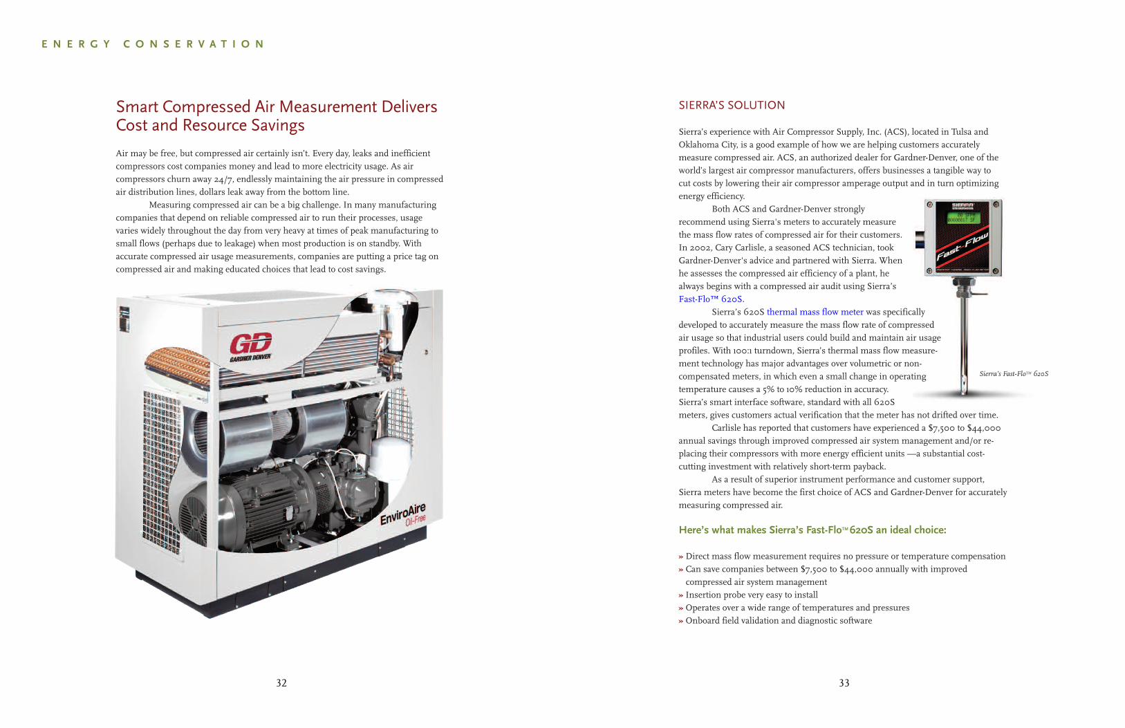
Sierra’s experience with Air Compressor Supply, Inc. (ACS), located in Tulsa andOklahoma City, is a good example of how we are helping customers accuratelymeasure compressed air. ACS, an authorized dealer for Gardner-Denver, one of theworld’s largest air compressor manufacturers, offers businesses a tangible way tocut costs by lowering their air compressor amperage output and in turn optimizingenergy efficiency.
Both ACS and Gardner-Denver strongly recommend using Sierra's meters to accurately measure the mass flow rates of compressed air for their customers. In 2002, Cary Carlisle, a seasoned ACS technician, took Gardner-Denver's advice and partnered with Sierra. When he assesses the compressed air efficiency of a plant, he always begins with a compressed air audit using Sierra’s Fast-Flo™ 620S.
Sierra’s 620S thermal mass flow meter was specifically developed to accurately measure the mass flow rate of compressed air usage so that industrial users could build and maintain air usage profiles. With 100:1 turndown, Sierra’s thermal mass flow measure-ment technology has major advantages over volumetric or non-compensated meters, in which even a small change in operatingtemperature causes a 5% to 10% reduction in accuracy.Sierra’s smart interface software, standard with all 620Smeters, gives customers actual verification that the meter has not drifted over time.
Carlisle has reported that customers have experienced a $7,500 to $44,000annual savings through improved compressed air system management and/or re-placing their compressors with more energy efficient units —a substantial cost-cutting investment with relatively short-term payback.
As a result of superior instrument performance and customer support,Sierra meters have become the first choice of ACS and Gardner-Denver for accuratelymeasuring compressed air.
Here’s what makes Sierra’s Fast-FloTM620S an ideal choice:
» Direct mass flow measurement requires no pressure or temperature compensation» Can save companies between $7,500 to $44,000 annually with improvedcompressed air system management
» Insertion probe very easy to install» Operates over a wide range of temperatures and pressures» Onboard field validation and diagnostic software
33
Sierra’s Fast-FloTM 620S
E N E R G Y C O N S E R V A T I O N
32
SIERRA’S SOLUTION
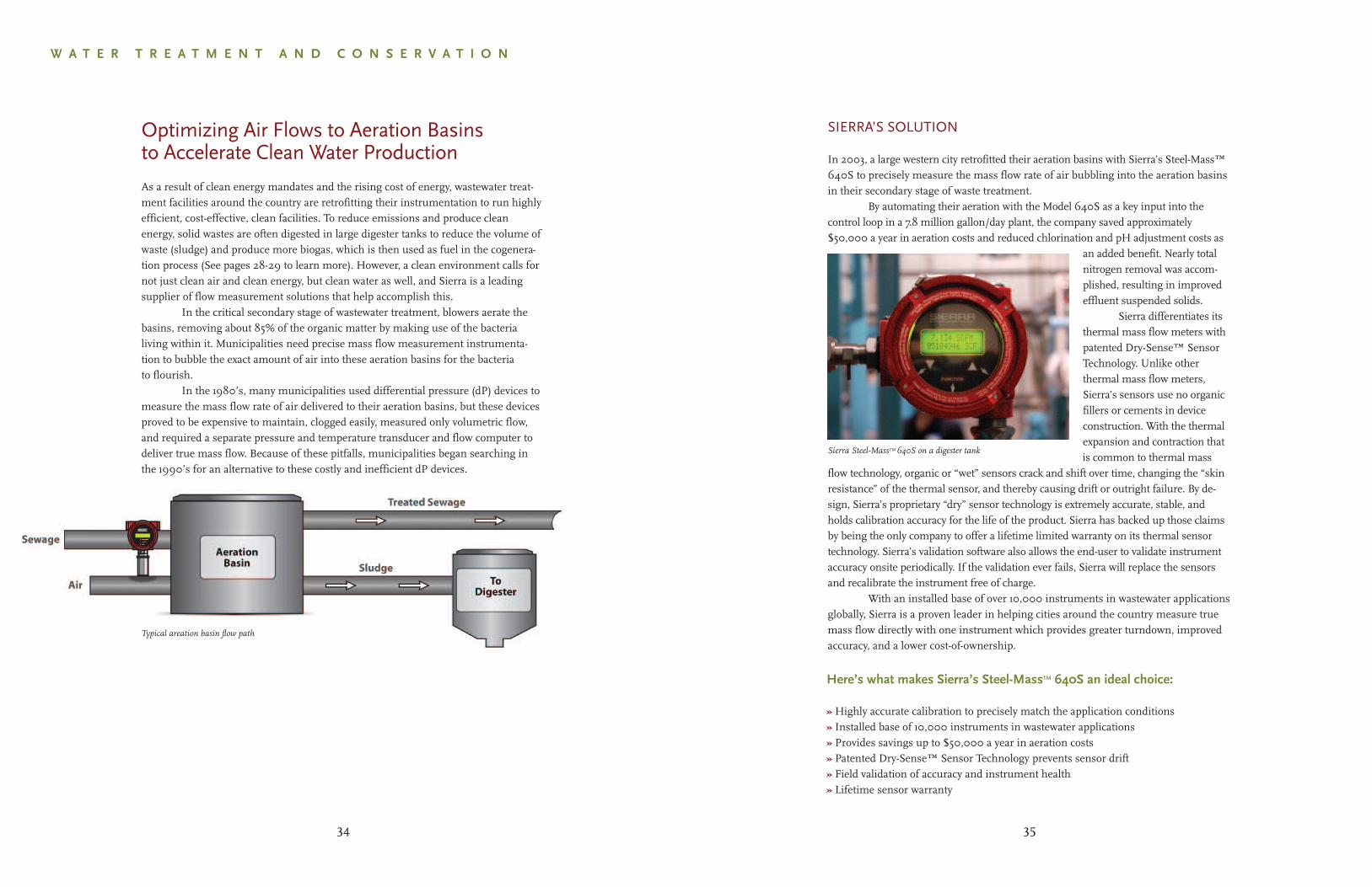
In 2003, a large western city retrofitted their aeration basins with Sierra’s Steel-Mass™640S to precisely measure the mass flow rate of air bubbling into the aeration basinsin their secondary stage of waste treatment.
By automating their aeration with the Model 640S as a key input into thecontrol loop in a 7.8 million gallon/day plant, the company saved approximately$50,000 a year in aeration costs and reduced chlorination and pH adjustment costs as
an added benefit. Nearly totalnitrogen removal was accom-plished, resulting in improvedeffluent suspended solids.
Sierra differentiates itsthermal mass flow meters withpatented Dry-Sense™ SensorTechnology. Unlike otherthermal mass flow meters,Sierra’s sensors use no organicfillers or cements in deviceconstruction. With the thermalexpansion and contraction thatis common to thermal mass
flow technology, organic or “wet” sensors crack and shift over time, changing the “skinresistance” of the thermal sensor, and thereby causing drift or outright failure. By de-sign, Sierra’s proprietary “dry” sensor technology is extremely accurate, stable, andholds calibration accuracy for the life of the product. Sierra has backed up those claimsby being the only company to offer a lifetime limited warranty on its thermal sensortechnology. Sierra’s validation software also allows the end-user to validate instrumentaccuracy onsite periodically. If the validation ever fails, Sierra will replace the sensorsand recalibrate the instrument free of charge.
With an installed base of over 10,000 instruments in wastewater applicationsglobally, Sierra is a proven leader in helping cities around the country measure truemass flow directly with one instrument which provides greater turndown, improvedaccuracy, and a lower cost-of-ownership.
Sierra Steel-MassTM640S on a digester tank
35
Here’s what makes Sierra’s Steel-MassTM 640S an ideal choice:
» Highly accurate calibration to precisely match the application conditions» Installed base of 10,000 instruments in wastewater applications» Provides savings up to $50,000 a year in aeration costs» Patented Dry-Sense™ Sensor Technology prevents sensor drift» Field validation of accuracy and instrument health» Lifetime sensor warranty
W A T E R T R E A T M E N T A N D C O N S E R V A T I O N
Optimizing Air Flows to Aeration Basinsto Accelerate Clean Water Production
As a result of clean energy mandates and the rising cost of energy, wastewater treat-ment facilities around the country are retrofitting their instrumentation to run highlyefficient, cost-effective, clean facilities. To reduce emissions and produce cleanenergy, solid wastes are often digested in large digester tanks to reduce the volume ofwaste (sludge) and produce more biogas, which is then used as fuel in the cogenera-tion process (See pages 28-29 to learn more). However, a clean environment calls fornot just clean air and clean energy, but clean water as well, and Sierra is a leadingsupplier of flow measurement solutions that help accomplish this.
In the critical secondary stage of wastewater treatment, blowers aerate thebasins, removing about 85% of the organic matter by making use of the bacterialiving within it. Municipalities need precise mass flow measurement instrumenta-tion to bubble the exact amount of air into these aeration basins for the bacteriato flourish.
In the 1980’s, many municipalities used differential pressure (dP) devices tomeasure the mass flow rate of air delivered to their aeration basins, but these devicesproved to be expensive to maintain, clogged easily, measured only volumetric flow,and required a separate pressure and temperature transducer and flow computer todeliver true mass flow. Because of these pitfalls, municipalities began searching inthe 1990’s for an alternative to these costly and inefficient dP devices.
Typical areation basin flow path
34
SIERRA’S SOLUTION
As the EPA’s rules on disinfecting by-products get stricter, more water treatmentfacilities are opting to use ozone systems for water purification instead of chlorine.Sierra’s Innova-Mass® helps water treatment plants precisely measure the flow rate ofoxygen entering these ozone generators.
Measuring the amount of ozone produced by the ozone generator is problem-atic since the ozone has a short lifetime. It cannot be stored and needs a short"residence time" in the piping and flow meter. The Sierra Innova-Mass® 240 vortexmeter is an in-line device that is fully flow-profile compensated, so that minimalstraight-run piping is required. Ozone is also produced at low pressures, so pressuredrop losses must be minimized. The Sierra Vortex meter does not appreciably obstructthe pipe so pressure drops are also minimal.
The generator requires a robust flow device that is well shielded from theCoronal discharge that produced the Ozone. Housed in an explosion-proof enclosure,the Sierra Innova-Mass® 240 vortex meter is virtually immune to the heavy electro-magnetic interference (EMI) an ozone generator can produce.
37
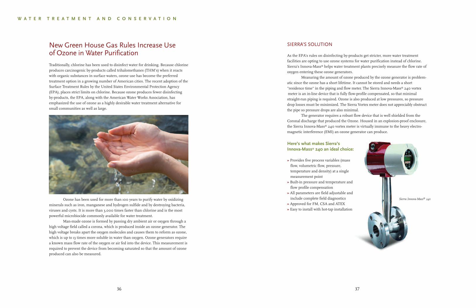
Sierra Innova-Mass® 240
Here’s what makes Sierra’sInnova-Mass® 240 an ideal choice:
» Provides five process variables (massflow, volumetric flow, pressure,temperature and density) at a singlemeasurement point
» Built-in pressure and temperature andflow profile compensation
» All parameters are field adjustable andinclude complete field diagnostics
» Approved for FM, CSA and ATEX» Easy to install with hot-tap installation
W A T E R T R E A T M E N T A N D C O N S E R V A T I O N
New Green House Gas Rules Increase Useof Ozone in Water Purification
Traditionally, chlorine has been used to disinfect water for drinking. Because chlorineproduces carcinogenic by-products called trihalomethanes (THM’s) when it reactswith organic substances in surface waters, ozone use has become the preferredtreatment option in a growing number of American cities. The recent adoption of theSurface Treatment Rules by the United States Environmental Protection Agency(EPA), places strict limits on chlorine. Because ozone produces fewer disinfectingby-products, the EPA, along with the American Water Works Association, hasemphasized the use of ozone as a highly desirable water treatment alternative forsmall communities as well as large.
Ozone has been used for more than 100 years to purify water by oxidizingminerals such as iron, manganese and hydrogen sulfide and by destroying bacteria,viruses and cysts. It is more than 3,000 times faster than chlorine and is the mostpowerful microbiocide commonly available for water treatment.
Man-made ozone is formed by passing dry ambient air or oxygen through ahigh voltage field called a corona, which is produced inside an ozone generator. Thehigh voltage breaks apart the oxygen molecules and causes them to reform as ozone,which is up to 13 times more soluble in water than oxygen. Ozone generators requirea known mass flow rate of the oxygen or air fed into the device. This measurement isrequired to prevent the device from becoming saturated so that the amount of ozoneproduced can also be measured.
36
SIERRA’S SOLUTION
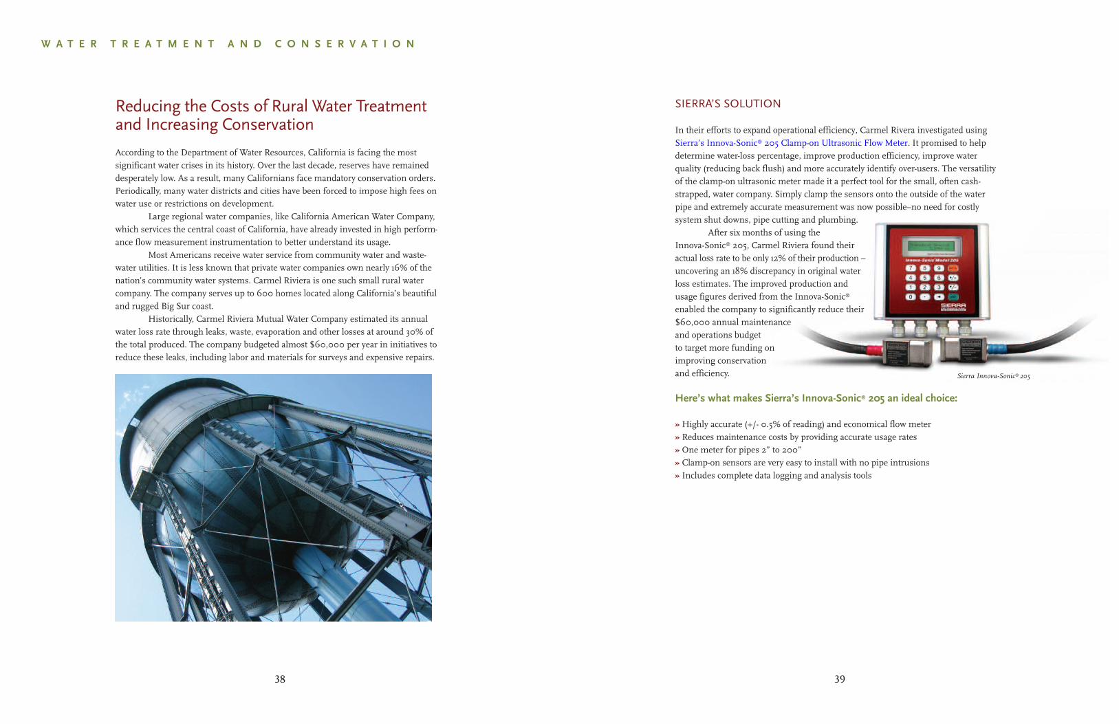
In their efforts to expand operational efficiency, Carmel Rivera investigated using Sierra’s Innova-Sonic® 205 Clamp-on Ultrasonic Flow Meter. It promised to help determine water-loss percentage, improve production efficiency, improve water quality (reducing back flush) and more accurately identify over-users. The versatility of the clamp-on ultrasonic meter made it a perfect tool for the small, often cash-strapped, water company. Simply clamp the sensors onto the outside of the water pipe and extremely accurate measurement was now possible–no need for costly system shut downs, pipe cutting and plumbing.
After six months of using theInnova-Sonic® 205, Carmel Riviera found theiractual loss rate to be only 12% of their production –uncovering an 18% discrepancy in original waterloss estimates. The improved production andusage figures derived from the Innova-Sonic®
enabled the company to significantly reduce their$60,000 annual maintenanceand operations budgetto target more funding onimproving conservationand efficiency.
Here’s what makes Sierra’s Innova-Sonic® 205 an ideal choice:
» Highly accurate (+/- 0.5% of reading) and economical flow meter» Reduces maintenance costs by providing accurate usage rates» One meter for pipes 2” to 200”» Clamp-on sensors are very easy to install with no pipe intrusions» Includes complete data logging and analysis tools
Sierra Innova-Sonic® 205
39
W A T E R T R E A T M E N T A N D C O N S E R V A T I O N
Reducing the Costs of Rural Water Treatmentand Increasing Conservation
According to the Department of Water Resources, California is facing the mostsignificant water crises in its history. Over the last decade, reserves have remaineddesperately low. As a result, many Californians face mandatory conservation orders.Periodically, many water districts and cities have been forced to impose high fees onwater use or restrictions on development.
Large regional water companies, like California American Water Company,which services the central coast of California, have already invested in high perform-ance flow measurement instrumentation to better understand its usage.
Most Americans receive water service from community water and waste-water utilities. It is less known that private water companies own nearly 16% of thenation’s community water systems. Carmel Riviera is one such small rural watercompany. The company serves up to 600 homes located along California’s beautifuland rugged Big Sur coast.
Historically, Carmel Riviera Mutual Water Company estimated its annualwater loss rate through leaks, waste, evaporation and other losses at around 30% ofthe total produced. The company budgeted almost $60,000 per year in initiatives toreduce these leaks, including labor and materials for surveys and expensive repairs.
38

Experience Our Passion for Flow!
sierrainstruments.com/cleanenergy

NORTH AMERICA5 Harris Court, Building L / Monterey, CA 93940 / USA
www.sierrainstruments.com800.866.0200 / 831.373.0200 / fax 831.373.4402
EUROPEThe Netherlands
+31 72 5071400 / fx +31 72 5071401
ASIA-PACIFICShanghai, China
+8621 5879 8521/22 / fx +8621 5879 8586