sidekick plus - australian tel-tec pty ltd€¦ · sidekick® plus user’s guide introduction the...
TRANSCRIPT

Sidekick® PlusUSER’S GUIDE

CUSTOMER TRAINING &TECHNICAL SUPPORTNOTICE: This document is an unpublished workprotected by United States copyright laws and isproprietary to Tempo. Disclosure, copying,reproduction, merger, translation, modification,enhancement, or use by anyone other thanauthorized employees or licensees of Tempo and itsaffiliate companies without prior consent of Tempois prohibited. Permission is granted to telephonecompanies to reproduce or otherwise use thismaterial for internal use only.
Copyright © 2006Sidekick® Plus is a registered trademark ofGreenlee Textron Inc.All rights reserved.
Printed in U.S.A.Part No. 1155-0528 REV. B (09/2006)
1390 Aspen Way, Vista, CA 92081PHONE 760-598-8900, 800-642-2155
FAX 760-598-5634M–F 7:00 a.m.–4:30 p.m. Pacific Time
www.tempo.textron.com
USER'S GUIDE • Sidekick Plus®
i
Sidekick® PlusUSER’S GUIDE
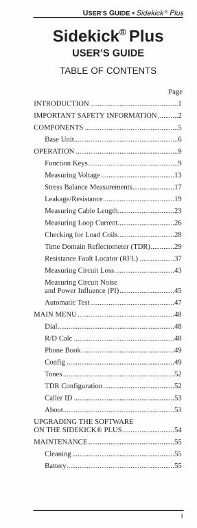
TABLE OF CONTENTS
Page
INTRODUCTION ................................................1
IMPORTANT SAFETY INFORMATION ...........2
COMPONENTS ...................................................5
Base Unit.........................................................6
OPERATION ........................................................9
Function Keys .................................................9
Measuring Voltage ........................................13
Stress Balance Measurements.......................17
Leakage/Resistance.......................................19
Measuring Cable Length...............................23
Measuring Loop Current...............................26
Checking for Load Coils...............................28
Time Domain Reflectometer (TDR).............29
Resistance Fault Locator (RFL) ...................37
Measuring Circuit Loss.................................43
Measuring Circuit Noise and Power Influence (PI) ..............................45
Automatic Test ..............................................47
MAIN MENU.....................................................48
Dial................................................................48
R/D Calc .......................................................48
Phone Book...................................................49
Config ...........................................................49
Tones .............................................................52
TDR Configuration .......................................52
Caller ID .......................................................53
About.............................................................53
UPGRADING THE SOFTWARE ON THE SIDEKICK® PLUS ............................54
MAINTENANCE ...............................................55
Cleaning ........................................................55
Battery...........................................................55

USER'S GUIDE • Sidekick Plus®
ii
WASTE ELECTRONICELECTRICAL EQUIPMENT ............................57
REPLACEMENT PARTSAND ACCESSORIES ........................................57
SPECIFICATIONS .............................................58
Sidekick® Plus .............................................58
Measurements ...............................................58
WARRANTY......................................................60
General Provisions........................................60
Work Hereunder............................................61
Specific Warranty Provisions........................61

Sidekick® PlusUSER’S GUIDE
INTRODUCTIONThe Sidekick® Plus facilitates the techni-cian’s work in the field. By combining thefunctions of a volt-ohmmeter, longitudinalbalance tester, and open meter with fivetransmission and noise tests, the Sidekick®Plus reduces repeat reports and improvesquality of service.
Added functions to the Sidekick® Plusinclude a time domain reflectometer (TDR)and a resistance fault locator (RFL).
The Sidekick® Plus intuitive user interfaceand USB communication make it necessaryequipment for field work.
The Sidekick® Plus is a compact, battery-powered instrument that can be convenientlyheld in the technician's hand.
For questions on operation, requests for fieldtraining, or for additional service, call TempoResearch in Vista, CA at 1-760-598-8900 ortoll free 1-800-642-2155. Outside of NorthAmerica, contact your local Tempo distribu-tor.
USER'S GUIDE • Sidekick Plus®
1

IMPORTANT SAFETYINFORMATIONSafety is essential in the use and maintenanceof Tempo equipment. This user’s guide andmarkings on the equipment provide informa-tion for avoiding hazards and unsafe practicesrelated to the use of this equipment.
USER'S GUIDE • Sidekick Plus®
2
IMPORTANT SAFETYINFORMATION
USER'S GUIDE • Sidekick Plus®
3

USER'S GUIDE • Sidekick Plus®
4
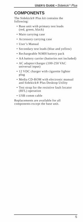
COMPONENTSThe Sidekick® Plus kit contains thefollowing:
• Base unit with primary test leads (red, green, black)
• Main carrying case
• Accessory carrying case
• User’s Manual
• Secondary test leads (blue and yellow)
• Rechargeable NiMH battery pack
• AA battery carrier (batteries not included)
• AC adapter/charger (100-250 VACuniversal input)
• 12 VDC charger with cigarette lighterplug
• Media CD-ROM with electronic manualand Sidekick® Plus Desktop Utility
• Test strap for the resistive fault locator(RFL) operation
• USB comm cable
Replacements are available for allcomponents except the base unit.
USER'S GUIDE • Sidekick Plus®
5
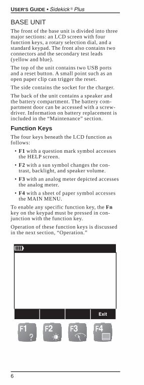
BASE UNITThe front of the base unit is divided into threemajor sections: an LCD screen with fourfunction keys, a rotary selection dial, and astandard keypad. The front also contains twoconnectors and the secondary test leads(yellow and blue).
The top of the unit contains two USB portsand a reset button. A small point such as anopen paper clip can trigger the reset.
The side contains the socket for the charger.
The back of the unit contains a speaker andthe battery compartment. The battery com-partment door can be accessed with a screw-driver. Information on battery replacement isincluded in the “Maintenance” section.
Function KeysThe four keys beneath the LCD function asfollows:
• F1 with a question mark symbol accessesthe HELP screen.
• F2 with a sun symbol changes the con-trast, backlight, and speaker volume.
• F3 with an analog meter depicted accessesthe analog meter.
• F4 with a sheet of paper symbol accessesthe MAIN MENU.
To enable any specific function key, the Fnkey on the keypad must be pressed in con-junction with the function key.
Operation of these function keys is discussedin the next section, “Operation.”
USER'S GUIDE • Sidekick Plus®
6
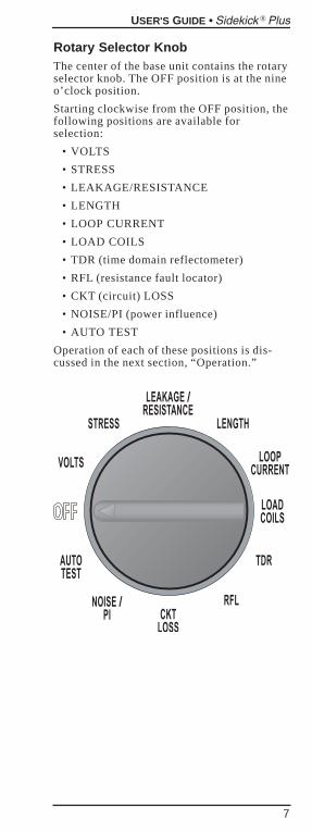
Rotary Selector KnobThe center of the base unit contains the rotaryselector knob. The OFF position is at the nineo’clock position.
Starting clockwise from the OFF position, thefollowing positions are available forselection:
• VOLTS
• STRESS
• LEAKAGE/RESISTANCE
• LENGTH
• LOOP CURRENT
• LOAD COILS
• TDR (time domain reflectometer)
• RFL (resistance fault locator)
• CKT (circuit) LOSS
• NOISE/PI (power influence)
• AUTO TEST
Operation of each of these positions is dis-cussed in the next section, “Operation.”
USER'S GUIDE • Sidekick Plus®
7
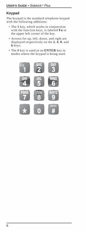
KeypadThe keypad is the standard telephone keypadwith the following additions:
• The 1 key, which works in conjunctionwith the function keys, is labeled Fn inthe upper left corner of the key.
• Arrows for up, left, down, and right aredisplayed respectively on the 2, 4, 8, and6 keys.
• The # key is used as an ENTER key inmodes where the keypad is being used.
USER'S GUIDE • Sidekick Plus®
8
OPERATION
NOTEFully charge the batteries for at least 8hours prior to first use.
IMPORTANTAll measurement functions are disabledwhen the AC power adapter is connectedto the Sidekick® Plus or when a connec-tion is detected on the USB port.
A visual display of battery power is alwaysdisplayed in the upper left corner of the LCDscreen. Each bar represents 25% power. Fullpower or 100% is shown as four bars.
A low battery warning flashes on the displayscreen when battery is in critical state. Theunit turns itself off if the low battery warningflashes for more than one minute
Move the rotary knob to any position toactivate the base unit. Once the base unit isactivated, the function keys can be accessed.
Press the Fn key on the keypad while simulta-neously pressing the appropriate function key.The LCD screen then displays the appropriateinformation.
The LCD display has a row at the bottom ofthe screen where new screens can be accessedwith the function keys below. It is not neces-sary to press the keypad Fn key to access themenu at the bottom of the LCD screen.
The first time a new Sidekick® Plus is pow-ered up, the user will be prompted to choosethe menu language to be used. This settingmay be changed at any time via the CONFIGmenu.
FUNCTION KEYS
F1 HELPAccess the HELP screen by pressing andholding the Fn key. Then press the F1 HELPfunction key.
This screen displays instructions directlyrelated to the position of the rotary selectorknob. If the knob is in the VOLTS position,the instructions explain how to obtain a volt-age measurement.
F3 Next accesses the next page in the instruc-tions. F4 Exit returns the display to where itwas when HELP was accessed.
USER'S GUIDE • Sidekick Plus®
9
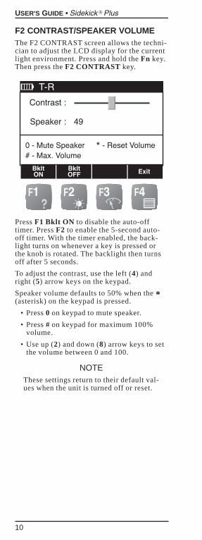
F2 CONTRAST/SPEAKER VOLUMEThe F2 CONTRAST screen allows the techni-cian to adjust the LCD display for the currentlight environment. Press and hold the Fn key.Then press the F2 CONTRAST key.
Press F1 Bklt ON to disable the auto-offtimer. Press F2 to enable the 5-second auto-off timer. With the timer enabled, the back-light turns on whenever a key is pressed orthe knob is rotated. The backlight then turnsoff after 5 seconds.
To adjust the contrast, use the left (4) andright (5) arrow keys on the keypad.
Speaker volume defaults to 50% when the *(asterisk) on the keypad is pressed.
• Press 0 on keypad to mute speaker.
• Press # on keypad for maximum 100%volume.
• Use up (2) and down (8) arrow keys to setthe volume between 0 and 100.
NOTEThese settings return to their default val-ues when the unit is turned off or reset.
USER'S GUIDE • Sidekick Plus®
10
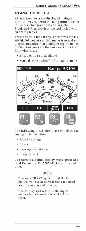
F3 ANALOG METERAll measurements are displayed in digitalform. However, because analog form is easierto see fast changes or peak values, theSidekick® Plus provides the technician withan analog meter.
Press and hold the Fn key. Then press the F3ANALOG key. An analog meter is now dis-played. Regardless of analog or digital mode,the function keys are the same except in thefollowing cases:
• 3-lead option not available
• Manual scale option for Resistance mode
The following Sidekick® Plus tests allow theanalog meter function:
• AC/DC voltage
• Stress
• Leakage/Resistance
• Loop Current
To return to a digital display mode, press andhold Fn and the F3 ANALOG key a secondtime.
NOTEThe word “REV” appears and flashes ifthe DC voltage or current has a reversedpolarity or a negative value.
The display will return to the digitalmode when the unit is turned off orreset.
USER'S GUIDE • Sidekick Plus®
11
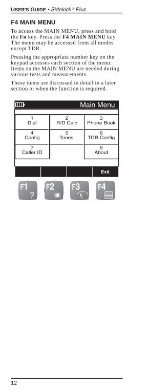
F4 MAIN MENUTo access the MAIN MENU, press and holdthe Fn key. Press the F4 MAIN MENU key.The menu may be accessed from all modesexcept TDR.
Pressing the appropriate number key on thekeypad accesses each section of the menu.Items on the MAIN MENU are needed duringvarious tests and measurements.
These items are discussed in detail in a latersection or when the function is required.
USER'S GUIDE • Sidekick Plus®
12
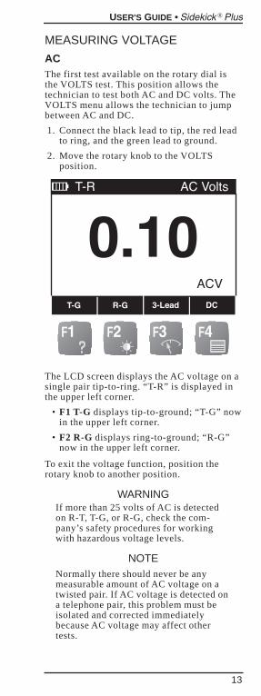
MEASURING VOLTAGE
ACThe first test available on the rotary dial isthe VOLTS test. This position allows thetechnician to test both AC and DC volts. TheVOLTS menu allows the technician to jumpbetween AC and DC.
1. Connect the black lead to tip, the red leadto ring, and the green lead to ground.
2. Move the rotary knob to the VOLTSposition.
The LCD screen displays the AC voltage on asingle pair tip-to-ring. “T-R” is displayed inthe upper left corner.
• F1 T-G displays tip-to-ground; “T-G” nowin the upper left corner.
• F2 R-G displays ring-to-ground; “R-G”now in the upper left corner.
To exit the voltage function, position therotary knob to another position.
WARNINGIf more than 25 volts of AC is detectedon R-T, T-G, or R-G, check the com-pany’s safety procedures for workingwith hazardous voltage levels.
NOTENormally there should never be anymeasurable amount of AC voltage on atwisted pair. If AC voltage is detected ona telephone pair, this problem must beisolated and corrected immediatelybecause AC voltage may affect othertests.
USER'S GUIDE • Sidekick Plus®
13
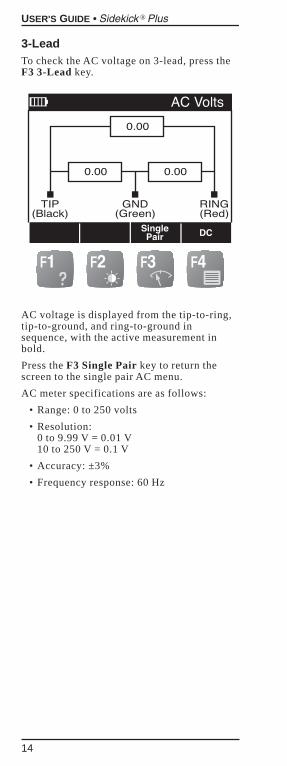
3-LeadTo check the AC voltage on 3-lead, press theF3 3-Lead key.
AC voltage is displayed from the tip-to-ring,tip-to-ground, and ring-to-ground insequence, with the active measurement inbold.
Press the F3 Single Pair key to return thescreen to the single pair AC menu.
AC meter specifications are as follows:
• Range: 0 to 250 volts
• Resolution: 0 to 9.99 V = 0.01 V10 to 250 V = 0.1 V
• Accuracy: ±3%
• Frequency response: 60 Hz
USER'S GUIDE • Sidekick Plus®
14
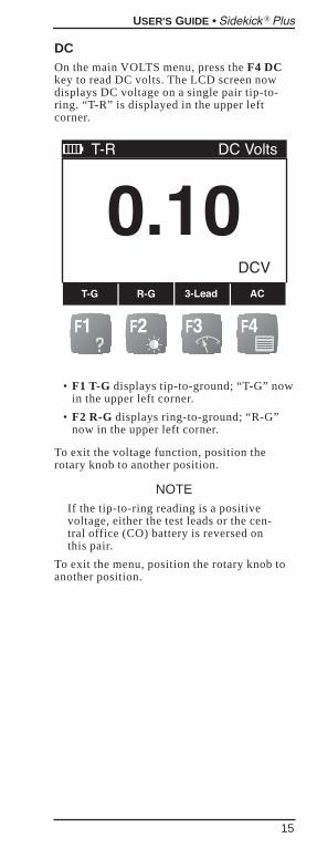
DCOn the main VOLTS menu, press the F4 DCkey to read DC volts. The LCD screen nowdisplays DC voltage on a single pair tip-to-ring. “T-R” is displayed in the upper leftcorner.
• F1 T-G displays tip-to-ground; “T-G” nowin the upper left corner.
• F2 R-G displays ring-to-ground; “R-G”now in the upper left corner.
To exit the voltage function, position therotary knob to another position.
NOTEIf the tip-to-ring reading is a positivevoltage, either the test leads or the cen-tral office (CO) battery is reversed onthis pair.
To exit the menu, position the rotary knob toanother position.
USER'S GUIDE • Sidekick Plus®
15
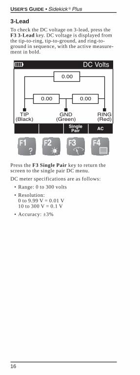
3-LeadTo check the DC voltage on 3-lead, press theF3 3-Lead key. DC voltage is displayed fromthe tip-to-ring, tip-to-ground, and ring-to-ground in sequence, with the active measure-ment in bold.
Press the F3 Single Pair key to return thescreen to the single pair DC menu.
DC meter specifications are as follows:
• Range: 0 to 300 volts
• Resolution: 0 to 9.99 V = 0.01 V10 to 300 V = 0.1 V
• Accuracy: ±3%
USER'S GUIDE • Sidekick Plus®
16
STRESS BALANCEMEASUREMENTSThe STRESS selection identifies and isolatesthe following:
• High joint or high resistance opens (series resistance faults)
• Capacitive imbalances (conductor lengths are unequal)
• Unbalanced load coils or build-outnetworks
• Crosses
• Grounds
• Split pairs
Stress Test EffectivenessThe stress test identifies capacitive imbal-ances (i.e., unequal conductor lengths) andDC problems (i.e., crosses and grounds)anywhere along the length of a dry or idle-working pair.
The STRESS measurement on the Sidekick®Plus is more sensitive to pair imbalance prob-lems than noise metallic and ordinary longi-tudinal balance tests. Series faults, however,that cause static noise on a single wire read30 dBrnC if there is less than 1,000 feet ofwire beyond the fault.
The closer the technician is to a fault, thehigher the stress reading will be.
When performing the test on complete end-to-end circuits, a reading of more than 30 isunacceptable. Acceptable is 0 to 20. Marginalis 21 to 30.
NOTEThe STRESS measurement does notidentify shorts because a shorted pair isbalanced and produces good stressednoise readings. Use the LEAKAGEmeasurement to identify shorts.
USER'S GUIDE • Sidekick Plus®
17
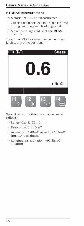
STRESS MeasurementTo perform the STRESS measurement:
1. Connect the black lead to tip, the red leadto ring, and the green lead to ground.
2. Move the rotary knob to the STRESSposition.
To exit the STRESS menu, move the rotaryknob to any other position.
Specifications for this measurement are asfollows:
• Range: 0 to 82 dBrnC
• Resolution: 0.1 dBrnC
• Accuracy: ±5 dBrnC overall; ±2 dBrnCfrom 10 to 50 dBrnC
• Longitudinal excitation: +90 dBrnC; ±6 dBrnC
USER'S GUIDE • Sidekick Plus®
18
LEAKAGE/RESISTANCE
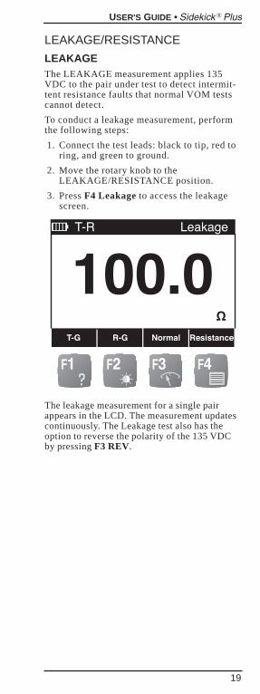
LEAKAGEThe LEAKAGE measurement applies 135VDC to the pair under test to detect intermit-tent resistance faults that normal VOM testscannot detect.
To conduct a leakage measurement, performthe following steps:
1. Connect the test leads: black to tip, red toring, and green to ground.
2. Move the rotary knob to theLEAKAGE/RESISTANCE position.
3. Press F4 Leakage to access the leakagescreen.
The leakage measurement for a single pairappears in the LCD. The measurement updatescontinuously. The Leakage test also has theoption to reverse the polarity of the 135 VDCby pressing F3 REV.
USER'S GUIDE • Sidekick Plus®
19
To change the measurement, use thefollowing function keys:
• F1 T-G to access tip-to-groundmeasurement.
• F2 R-G to access ring-to-groundmeasurement.
• F3 REV to reverse polarity.
• F4 Resist is for the resistance measure-ment discussed in the next section.
To exit the LEAKAGE menu, position therotary knob to another position or press theF4 Resist key to access resistance measuring.
Leakage specifications are as follows:
• Range: 0 to 100 MΩ, autoranging
• Resolution: 10 kΩ• Accuracy: ±3%
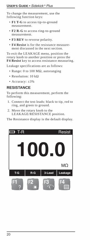
RESISTANCETo perform this measurement, perform thefollowing:
1. Connect the test leads: black to tip, red toring, and green to ground.
2. Move the rotary knob to theLEAKAGE/RESISTANCE position.
The Resistance display is the default display.
USER'S GUIDE • Sidekick Plus®
20
The initial LCD screen displays single pairresistance for tip-to-ring. The function keyshave the following choices:
• F1 T-G to access tip-to-groundmeasurement.
• F2 R-G to access ring-to-groundmeasurement.
• F3 3-Lead to display all three leads.
• F4 Leakage is for the leakage measure-ment discussed in the previous section.
To exit the Resistance menu, position therotary knob to another position or press the F4Leakage key to access the leakagemeasurement.
USER'S GUIDE • Sidekick Plus®
21
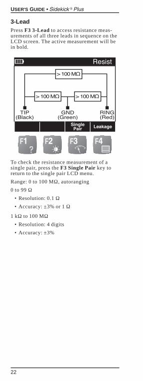
3-LeadPress F3 3-Lead to access resistance meas-urements of all three leads in sequence on theLCD screen. The active measurement will bein bold.
To check the resistance measurement of asingle pair, press the F3 Single Pair key toreturn to the single pair LCD menu.
Range: 0 to 100 MΩ, autoranging
0 to 99 Ω• Resolution: 0.1 Ω• Accuracy: ±3% or 1 Ω
1 kΩ to 100 MΩ• Resolution: 4 digits
• Accuracy: ±3%
USER'S GUIDE • Sidekick Plus®
22
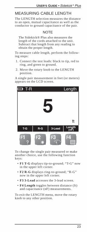
MEASURING CABLE LENGTHThe LENGTH selection measures the distanceto an open, mutual capacitance as well as theconductor to ground capacitance of the pair.
NOTEThe Sidekick® Plus also measures thelength of the cords attached to the unit.Subtract that length from any reading toobtain the proper length.
To measure cable length, perform the follow-ing steps:
1. Connect the test leads: black to tip, red toring, and green to ground.
2. Move the rotary knob to the LENGTHposition.
A single pair measurement in feet (or meters)appears on the LCD screen.
To change the single pair measured or makeanother choice, use the following functionkeys:
• F1 T-G displays tip-to-ground; “T-G” nowin the upper left corner.
• F2 R-G displays ring-to-ground; “R-G”now in the upper left corner.
• F3 3-Lead accesses the 3-lead screen.
• F4 Length toggles between distance (ft)and capacitance (nF) measurements.
To exit the LENGTH menu, move the rotaryknob to any other position.
USER'S GUIDE • Sidekick Plus®
23
Changing Capacitance per DistanceUse the up (2) and down (8) keys to adjustcapacitance per unit length displayed in theupper right of the screen. Adjust the capaci-tance per distance value to match a knownlength of cable or a known capacitance perdistance for a given cable.
Note that there are two capacitance per dis-tance values. One is for the T-G and R-Gcapacitance, while the other is for T-R.
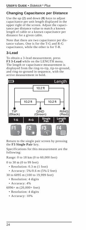
3-LeadTo obtain a 3-lead measurement, press F3 3-Lead while on the LENGTH menu. The length or capacitance measurement isdisplayed from the ring-to-tip, tip-to-ground,and ring-to-ground in sequence, with theactive measurement in bold.
Return to the single pair screen by pressingthe F3 Single Pair key.
Specifications for this measurement are thefollowing:
Range: 0 to 18 km (0 to 60,000 feet)
0 to 30 m (0 to 99 feet)• Resolution: 0.3 m (1 foot)• Accuracy: 5%/0.6 m (5%/2 feet)
30 to 6095 m (100 to 19,999 feet)• Resolution: 4 digits• Accuracy: 4%
6096+ m (20,000+ feet)• Resolution: 4 digits• Accuracy: 10%
USER'S GUIDE • Sidekick Plus®
24
Changing Distance UnitsThe distance measurement may be toggledbetween feet and meters through the MAINMENU screen.
1. Press and hold the Fn key.
2. Press F4.
3. Once the MAIN MENU is displayed, press4 on the keypad to enter the CONFIGsection.
4. Press F3 Next until the DEVICE SET-TING screen appears.
5. If necessary, use the up (2) or down (8)arrow keys on the keypad to highlight the“Length Unit.”
6. Use the left (4) or right (6) arrow key totoggle between “ft” and “meter.”
To exit back to the MAIN MENU, press F4.
USER'S GUIDE • Sidekick Plus®
25
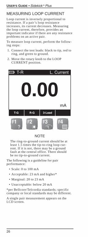
MEASURING LOOP CURRENTLoop current is inversely proportional toresistance. If a pair’s loop resistanceincreases, its current decreases. Measuringthe loop current, therefore, provides animportant indicator if there are any resistanceproblems on an active pair.
To measure loop current, perform the follow-ing steps:
1. Connect the test leads: black to tip, red toring, and green to ground.
2. Move the rotary knob to the LOOPCURRENT position.
NOTEThe ring-to-ground current should be atleast 1.5 times the tip-to-ring loop cur-rent. If it is not, there may be a groundfault at the central office. There shouldbe no tip-to-ground current.
The following is a guideline for pairperformance:
• Scale: 0 to 100 mA
• Acceptable: 23 mA and higher*
• Marginal: 20 to 23 mA
• Unacceptable: below 20 mA
*per Bellcore/Telcordia standards; specificcompany or local standards may be different.
A single pair measurement appears on theLCD screen.
USER'S GUIDE • Sidekick Plus®
26
To change the single pair measured or makeanother choice, use the following functionkeys:
• F1 T-G displays tip-to-ground; “T-G” nowin the upper left corner.
• F2 R-G displays ring-to-ground; “R-G”now in the upper left corner.
• F3 3-Lead accesses the 3-lead screen.
To exit the LOOP CURRENT menu, move therotary knob to any other position.
3-LeadTo access the 3-lead screen, press F3 3-Lead.The initial measurements of the tip-to-ringand ring-to-ground occur when the LCDscreen first appears.
The measurements are shown in sequence,with the active measurement in bold.
Return to the single pair screen by pressingthe F3 Single Pair key.
Current meter specifications are as follows:
• Range: 0 to 100 mA
• Resolution: 0 to 9.99 mA = 0.01 mA10 to 100 mA = 0.1 mA
• Accuracy: ±2 mA
USER'S GUIDE • Sidekick Plus®
27
CHECKING FOR LOAD COILSTo check for load coils, perform the follow-ing steps:
1. Connect the test leads: black to tip, red toring, and green to ground.
2. Move the rotary knob to the LOAD COILSposition.
The graph represents the impedance of theline. It reveals the load coils as a dip and thecorresponding peak. F1 ReTest allows thetechnician to double-check the test.
NOTEThe C.O. battery should be disconnectedduring detection of load coils. SomeC.O. battery and office connections canmask one to all coils from beingdetected. If problems exist on a pair,three or fewer load coils may bedetected. For example, if the trouble ison the end segment of a pair, the fourthload coil may not be detected.
USER'S GUIDE • Sidekick Plus®
28
TIME DOMAIN REFLECTOMETER(TDR)The TDR position of the rotary knob convertsthe Sidekick® Plus into a time domainreflectometer that sends out pulses of energyand then measures the time interval of thereflections.
The way energy is reflected and the amountof the energy reflected indicate the conditionof the cable. A TDR can detect normal occur-rences such as taps, splitters, couplers, andloop extenders. It also can accurately pin-point trouble such as shorts and opens. A TDRalso provides a rough estimate of the totalamount of cable that is wet and the approxi-mate location of the wet section.
The TDR displays a graph of the tested cablewith distance (time to reflection) on the hori-zontal axis. The on-screen cursor helps bydisplaying in feet or meters to a point on thecable. The vertical axis on the TDR screenshows the type and severity of the fault.
1. Connect the test leads: red to ring andblack to tip.
2. Move the rotary knob to the TDR position.
A TDR must know the characteristics of thecable to accurately display the distance tofaults. The Sidekick® Plus has the character-istics of some cable types preset.
Cable type can be selected through the MAINMENU screen, selection 6, or through theTDR main screen.
On the TDR menu screen:
1. Press and hold Fn.
2. Press the F4 key.
USER'S GUIDE • Sidekick Plus®
29
Cable Type
Use the keypad arrow keys (2 and 8) to scrollthrough the cable types. Once the correct onehas been highlighted, press the F4 key to exit.
If the cable type is not listed, the user maycreate a new cable type.
Press F2 Define Cable.“Custom Cable” isthen highlighted with the following newchoices:
• F2 DIA to change diameter. Use the key-pad arrow keys (4 and 6) to change thesetting.
• F3 VP to change velocity of propagation.Use keypad to type in new figure. VP isentered in 0.xx format.
Press F4 when the cable is selected or“Custom Cable” is defined.
NOTEThe unit returns to its default settingswhen turned off or reset.
Measuring and Reading TracesThe TDR main display contains the followingcontrols:
• Gain: Up (2) or down (8) arrows changethe gain of the TDR receiver.
• Marker: F1 displays a marker at the cur-rent location of the cursor. The distancefrom the marker to the cursor is displayedon the right side of the screen next to thedelta signal.
• Expand: F2 expands the section of cableinside the cursor box.
• Less Cable: F3 shortens the amount ofcable examined.
USER'S GUIDE • Sidekick Plus®
30
• More Cable: F4 increases the amount ofcable examined.
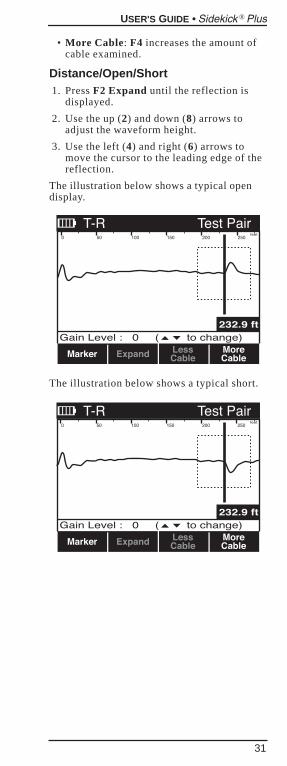
Distance/Open/Short1. Press F2 Expand until the reflection is
displayed.
2. Use the up (2) and down (8) arrows toadjust the waveform height.
3. Use the left (4) and right (6) arrows tomove the cursor to the leading edge of thereflection.
The illustration below shows a typical opendisplay.
The illustration below shows a typical short.
USER'S GUIDE • Sidekick Plus®
31
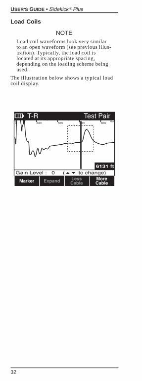
Load Coils
NOTELoad coil waveforms look very similarto an open waveform (see previous illus-tration). Typically, the load coil islocated at its appropriate spacing,depending on the loading scheme beingused.
The illustration below shows a typical loadcoil display.
USER'S GUIDE • Sidekick Plus®
32
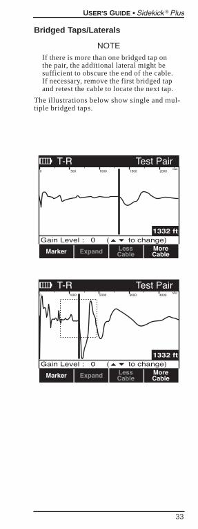
Bridged Taps/Laterals
NOTEIf there is more than one bridged tap onthe pair, the additional lateral might besufficient to obscure the end of the cable.If necessary, remove the first bridged tapand retest the cable to locate the next tap.
The illustrations below show single and mul-tiple bridged taps.
USER'S GUIDE • Sidekick Plus®
33
USER'S GUIDE • Sidekick Plus®
34
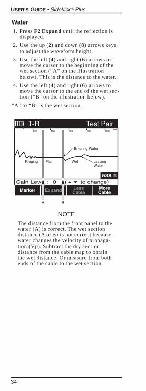
Water1. Press F2 Expand until the reflection is
displayed.
2. Use the up (2) and down (8) arrows keysto adjust the waveform height.
3. Use the left (4) and right (6) arrows tomove the cursor to the beginning of thewet section (“A” on the illustrationbelow). This is the distance to the water.
4. Use the left (4) and right (6) arrows tomove the cursor to the end of the wet sec-tion (“B” on the illustration below).
“A” to “B” is the wet section.
NOTEThe distance from the front panel to thewater (A) is correct. The wet sectiondistance (A to B) is not correct becausewater changes the velocity of propaga-tion (Vp). Subtract the dry sectiondistance from the cable map to obtainthe wet distance. Or measure from bothends of the cable to the wet section.
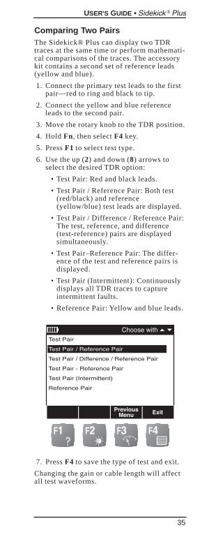
Comparing Two PairsThe Sidekick® Plus can display two TDRtraces at the same time or perform mathemati-cal comparisons of the traces. The accessorykit contains a second set of reference leads(yellow and blue).
1. Connect the primary test leads to the firstpair—red to ring and black to tip.
2. Connect the yellow and blue referenceleads to the second pair.
3. Move the rotary knob to the TDR position.
4. Hold Fn, then select F4 key.
5. Press F1 to select test type.
6. Use the up (2) and down (8) arrows toselect the desired TDR option:
• Test Pair: Red and black leads.
• Test Pair / Reference Pair: Both test(red/black) and reference(yellow/blue) test leads are displayed.
• Test Pair / Difference / Reference Pair:The test, reference, and difference(test-reference) pairs are displayedsimultaneously.
• Test Pair–Reference Pair: The differ-ence of the test and reference pairs isdisplayed.
• Test Pair (Intermittent): Continuouslydisplays all TDR traces to captureintermittent faults.
• Reference Pair: Yellow and blue leads.
7. Press F4 to save the type of test and exit.
Changing the gain or cable length will affectall test waveforms.
USER'S GUIDE • Sidekick Plus®
35
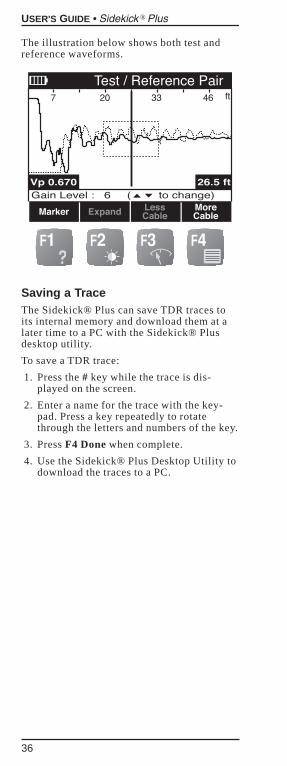
The illustration below shows both test andreference waveforms.
Saving a TraceThe Sidekick® Plus can save TDR traces toits internal memory and download them at alater time to a PC with the Sidekick® Plusdesktop utility.
To save a TDR trace:
1. Press the # key while the trace is dis-played on the screen.
2. Enter a name for the trace with the key-pad. Press a key repeatedly to rotatethrough the letters and numbers of the key.
3. Press F4 Done when complete.
4. Use the Sidekick® Plus Desktop Utility todownload the traces to a PC.
USER'S GUIDE • Sidekick Plus®
36
RESISTANCE FAULT LOCATOR(RFL)The RFL position of the rotary knob providesa resistance fault locator that reads out thedistance to high and low resistive shorts,grounds, crosses, and battery crosses.Readings show the distance to the far endstrap, the distance to the fault, and the dis-tance from the strap to the fault.
The faults can be either low or high resistanceor solid or varying (wet). The readings areaccurate even with voltage present (batterycontacts). The locator is fully automatic andprovides digital readouts with no nulls to set.Accuracy is within ±0.5%.
Low and high resistance shorts, earths, con-tacts, and battery faults need either one ortwo good conductors to bridge the faultedwire between accesses. If only one conductoris used, it must be the same gauge and lengthas the faulted conductor.
Two Good ConductorsFor the most accurate results, two good con-ductors must be used to short the yellow,blue, and red leads together at the far end.The two good conductors may be of anygauge or temperature. They can be eitherlonger or shorter than the faulted conductor.Wire left on a reel or strung in a short-cutbetween accesses does not affect readings.
These conductors must test good, reach thefar end, and be strapped to the faulted con-ductor.
One Good ConductorIf two good conductors are not available, theRFL can work in 3-lead mode with the yellowlead unused. If 3-lead mode is used, the bluelead conductor must be in the same cable asthe red. Use the strap included in the acces-sories case to short the two conductorstogether at the far end.
The measurement for fault to strap iscalculated in this mode and is denoted by a(C) following the value.
USER'S GUIDE • Sidekick Plus®
37
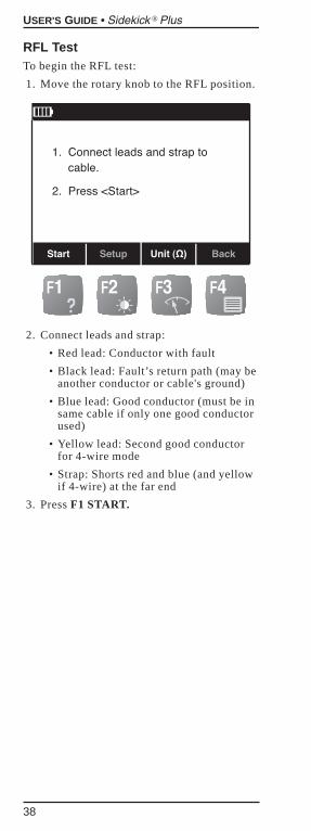
RFL TestTo begin the RFL test:
1. Move the rotary knob to the RFL position.
2. Connect leads and strap:
• Red lead: Conductor with fault
• Black lead: Fault’s return path (may beanother conductor or cable's ground)
• Blue lead: Good conductor (must be insame cable if only one good conductorused)
• Yellow lead: Second good conductorfor 4-wire mode
• Strap: Shorts red and blue (and yellowif 4-wire) at the far end
3. Press F1 START.
USER'S GUIDE • Sidekick Plus®
38
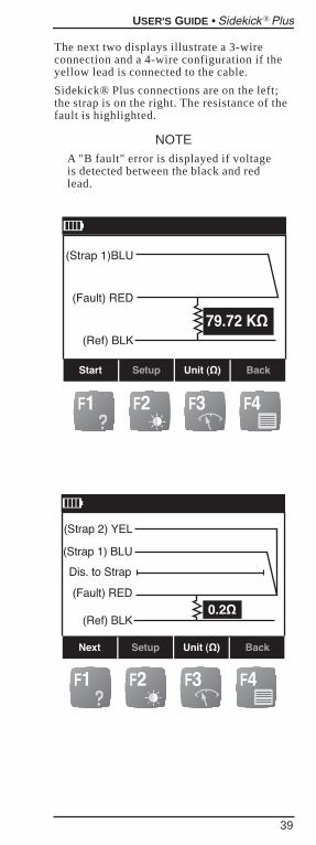
The next two displays illustrate a 3-wireconnection and a 4-wire configuration if theyellow lead is connected to the cable.
Sidekick® Plus connections are on the left;the strap is on the right. The resistance of thefault is highlighted.
NOTEA "B fault" error is displayed if voltageis detected between the black and redlead.
USER'S GUIDE • Sidekick Plus®
39
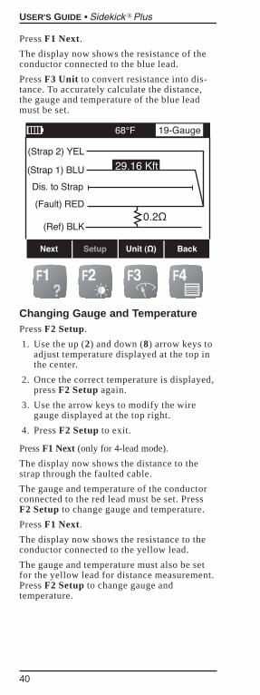
Press F1 Next.
The display now shows the resistance of theconductor connected to the blue lead.
Press F3 Unit to convert resistance into dis-tance. To accurately calculate the distance,the gauge and temperature of the blue leadmust be set.
Changing Gauge and TemperaturePress F2 Setup.
1. Use the up (2) and down (8) arrow keys toadjust temperature displayed at the top inthe center.
2. Once the correct temperature is displayed,press F2 Setup again.
3. Use the arrow keys to modify the wiregauge displayed at the top right.
4. Press F2 Setup to exit.
Press F1 Next (only for 4-lead mode).
The display now shows the distance to thestrap through the faulted cable.
The gauge and temperature of the conductorconnected to the red lead must be set. PressF2 Setup to change gauge and temperature.
Press F1 Next.
The display now shows the resistance to theconductor connected to the yellow lead.
The gauge and temperature must also be setfor the yellow lead for distance measurement.Press F2 Setup to change gauge andtemperature.
USER'S GUIDE • Sidekick Plus®
40
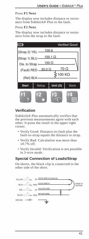
Press F1 Next.
The display now includes distance or resist-ance from Sidekick® Plus to the fault.
Press F1 Next.
The display now includes distance or resist-ance from the strap to the fault.
VerificationSidekick® Plus automatically verifies thatthe previous measurements agree with eachother. It posts the result in the upper rightcorner.
• Verify Good: Distance-to-fault plus thefault-to-strap equals the distance to strap.
• Verify Bad: Calculation was more than±0.7% off.
• Verify Invalid: Verification is not possiblein 3-wire mode.
Special Connection of Leads/StrapOn shorts, the black clip is connected to theother side of the short.
USER'S GUIDE • Sidekick Plus®
41
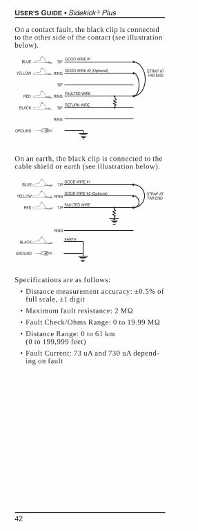
On a contact fault, the black clip is connectedto the other side of the contact (see illustrationbelow).
On an earth, the black clip is connected to thecable shield or earth (see illustration below).
Specifications are as follows:
• Distance measurement accuracy: ±0.5% offull scale, ±1 digit
• Maximum fault resistance: 2 MΩ• Fault Check/Ohms Range: 0 to 19.99 MΩ• Distance Range: 0 to 61 km
(0 to 199,999 feet)
• Fault Current: 73 uA and 730 uA depend-ing on fault
USER'S GUIDE • Sidekick Plus®
42
MEASURING CIRCUIT LOSSThe CKT LOSS selection measures the signalattenuation on the pair from the central office(C.O.) to the point of test. Values less than 0 dB display as a negative number.
The test requires an 0 dB test signal transmit-ted from the C.O.
The farther away from the test signal’s injec-tion point, the more loss because of theincreased distance the signal must travel.Because circuit loss is cumulative, the read-ing taken at the point of test indicates thetotal loss present on a pair.
1. Connect the test leads: black to tip, red toring, and green to ground.
2. Move the rotary knob to the CKT LOSSposition.
3. Activate the test signal by dialing from anexternal buttset or with the Sidekick®Plus internal dialing menu.
4. Press F4 to access the internal dialingmenu. Refer to the “Main Menu” sectionfor details on internal dialing.
To exit the CKT LOSS menu, position therotary knob to another position.
The following chart is a guideline for pairperformance:
• Acceptable: 0 to –8.5 dB
• Marginal: –8.6 to –10.0 dB
• Unacceptable: Below –10 dB
Specifications for the circuit loss measure-ments are as follows:
• Range: +3 to –45 dB
• Resolution: 0.1 dB
• Accuracy: ±0.5 dB
USER'S GUIDE • Sidekick Plus®
43

NOTES
USER'S GUIDE • Sidekick Plus®
44
MEASURING CIRCUIT NOISEAND POWER INFLUENCE (PI)The circuit noise and power influence meas-urements are performed on the same display.
Power InfluenceThe power influence measurement specifi-cally identifies electromagnetic interferences(EMI) from external sources (mainly powerlines). When this test is activated, theSidekick® Plus shorts ring and tip whilesimultaneously measuring the noise toground.
Circuit NoiseCircuit noise on cable pairs is generatedinternally by pair imbalances or externally byC.O. equipment, subscriber equipment, orelectromagnetic interference (EMI) equip-ment (radio transmitters, generators, trans-formers, etc.).
Normally, a poor ground or sheath on thecable pair or the external equipment allowsnoise to “leak” onto the cable pair.
BalanceBalance is a longitudinal measurementcalculated by subtracting the “circuit noise”measurement from the “power influence”measurement. Balance represents the overallquality of those measurements.
When the “power influence” and “circuitnoise” measurements are complete,Sidekick® Plus automatically calculates anddisplays the balance.
Sidekick® Plus measures the amount of cir-cuit noise present across tip and ring.
1. Connect the black lead to tip, the red leadto ring, and the green lead to ground.
2. Move the rotary knob to the NOISE/PIposition; the reading immediately appearson the LCD screen.
3. Use the down (8) arrow key to highlightthe “Noise” line.
USER'S GUIDE • Sidekick Plus®
45
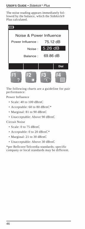
The noise reading appears immediately fol-lowed by the balance, which the Sidekick®Plus calculated.
The following charts are a guideline for pairperformance:
Power Influence
• Scale: 40 to 100 dBrnC
• Acceptable: 60 to 80 dBrnC*
• Marginal: 81 to 90 dBrnC
• Unacceptable: Above 90 dBrnC
Circuit Noise
• Scale: 0 to 75 dBrnC
• Acceptable: 0 to 20 dBrnC*
• Marginal: 21 to 30 dBrnC
• Unacceptable: Above 30 dBrnC
*per Bellcore/Telcordia standards; specificcompany or local standards may be different.
USER'S GUIDE • Sidekick Plus®
46
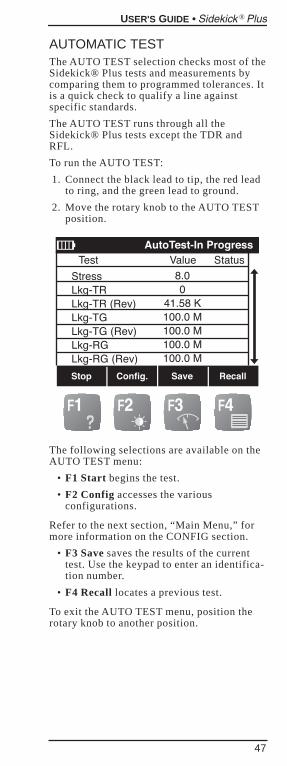
AUTOMATIC TESTThe AUTO TEST selection checks most of theSidekick® Plus tests and measurements bycomparing them to programmed tolerances. Itis a quick check to qualify a line againstspecific standards.
The AUTO TEST runs through all theSidekick® Plus tests except the TDR andRFL.
To run the AUTO TEST:
1. Connect the black lead to tip, the red leadto ring, and the green lead to ground.
2. Move the rotary knob to the AUTO TESTposition.
The following selections are available on theAUTO TEST menu:
• F1 Start begins the test.
• F2 Config accesses the variousconfigurations.
Refer to the next section, “Main Menu,” formore information on the CONFIG section.
• F3 Save saves the results of the currenttest. Use the keypad to enter an identifica-tion number.
• F4 Recall locates a previous test.
To exit the AUTO TEST menu, position therotary knob to another position.
USER'S GUIDE • Sidekick Plus®
47
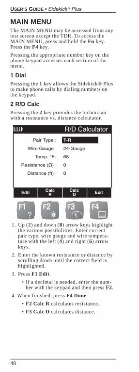
MAIN MENUThe MAIN MENU may be accessed from anytest screen except the TDR. To access theMAIN MENU, press and hold the Fn key.Press the F4 key.
Pressing the appropriate number key on thephone keypad accesses each section of themenu.
1 DialPressing the 1 key allows the Sidekick® Plusto make phone calls by dialing numbers onthe keypad.
2 R/D CalcPressing the 2 key provides the technicianwith a resistance vs. distance calculator.
1. Up (2) and down (8) arrow keys highlightthe various possibilities. Enter correctpair type, wire gauge and wire tempera-ture with the left (4) and right (6) arrowkeys.
2. Enter the known resistance or distance byscrolling down until the correct field ishighlighted.
3. Press F1 Edit.
• If a decimal is needed, enter the num-ber with the keypad and then press F2.
4. When finished, press F4 Done.
• F2 Calc R calculates resistance.
• F3 Calc D calculates distance.
USER'S GUIDE • Sidekick Plus®
48
3 Phone BookWhen the 3 key is pressed, the phone book isaccessed. A list of names previously enteredappears with the following choices:
• F1 Dial dials the person/numberhighlighted.
• F2 New adds a new person/number.
• F3 Delete deletes the person/numberhighlighted.
• F4 Exit returns to the MAIN MENU.
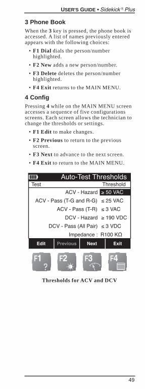
4 ConfigPressing 4 while on the MAIN MENU screenaccesses a sequence of five configurationsscreens. Each screen allows the technician tochange the thresholds or settings.
• F1 Edit to make changes.
• F2 Previous to return to the previousscreen.
• F3 Next to advance to the next screen.
• F4 Exit to return to the MAIN MENU.
Thresholds for ACV and DCV
USER'S GUIDE • Sidekick Plus®
49
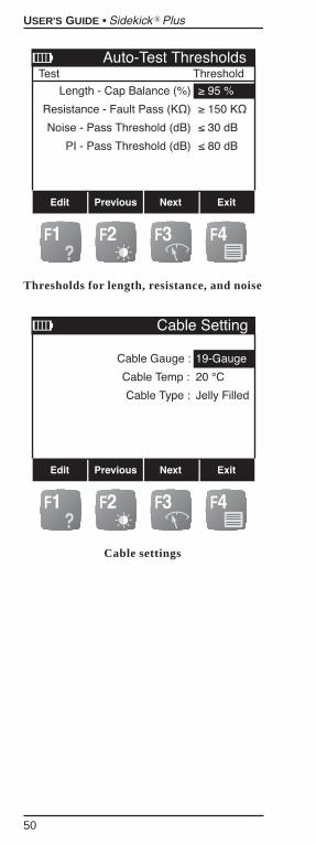
Thresholds for length, resistance, and noise
Cable settings
USER'S GUIDE • Sidekick Plus®
50
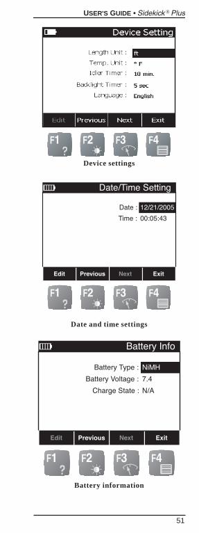
Device settings
Date and time settings
Battery information
USER'S GUIDE • Sidekick Plus®
51
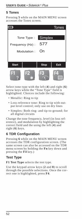
5 TonesPressing 5 while on the MAIN MENU screenaccesses the Tones screen.
Select tone type with the left (4) and right (6)arrow keys while the “Tone Type” field ishighlighted. Choices include the following:
• Metallic: Ring to tip
• Loss reference tone: Ring to tip with out-put level control; only use on dry lines
• Simplex: Both ring- and tip-to-ground; forall digital circuits
Change the tone frequency, level (in loss ref-erence), and modulation by highlighting thecorrect field and the using the left (4) andright (6) keys.
6 TDR ConfigurationPressing 6 while on the MAIN MENU screenaccesses the TDR configuration screen. (Thesame screen can also be accessed on the TDRmenu screen by holding the Fn key down andpressing the F4 key.)
Test TypeF1 Test Type selects the test type.
Use the keypad arrow keys (2 and 8) to scrollthrough the possible selections. Once the cor-rect one is highlighted, press F4.
USER'S GUIDE • Sidekick Plus®
52
Cable TypeUse the keypad arrow keys (2 and 8) to scrollthrough the cable types. Once the correct onehas been highlighted, press F4 key to exit.
If the cable type is not listed, the user maycreate a new cable type.
Press F2 Define Cable.“Custom Cable” isthen highlighted with the following newchoices:
• F2 DIA to change diameter. Use the key-pad arrow keys (4 and 6) to change thesetting.
• F3 VP to change velocity of propagation.Use keypad to type in new figure.
Press F4 when the cable is selected or“Custom Cable” is defined.
7 Caller IDPressing 7 while on the MAIN MENU screenidentifies the incoming call.
Press F4 Exit to return to the MAIN MENU.
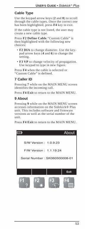
9 AboutPressing 9 while on the MAIN MENU screenaccesses information on the Sidekick® Plusunit. This includes software and firmwareversions as well as the serial number of theunit.
Press F4 Exit to return to the MAIN MENU.
USER'S GUIDE • Sidekick Plus®
53
UPGRADING THE SOFTWAREON THE SIDEKICK® PLUS1. Connect the Sidekick® Plus to be
upgraded to a PC using the supplied USBcable.
2. From the Sidekick® Plus Desktop Utilityapplication, click the button labeled“Update Sidekick® Plus Software”.
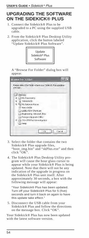
A “Browse For Folder” dialog box willappear.
3. Select the folder that contains the twoSidekick® Plus upgrade files,“boot_img.bin” and “skPlus.exe” and thenclick “OK”.
4. The Sidekick® Plus Desktop Utility pro-gram will cause the hour glass cursor toappear while your Sidekick® Plus is beingupdated. Note that there will not be anyindication of the upgrade in progress onthe Sidekick® Plus unit itself. Afterapproximately 30 seconds, a box with thefollowing message will appear:
“Your Sidekick® Plus has been updated.Turn off your Sidekick® Plus for 5 (five)seconds and turn it back on again to havethis update take effect.”
5. Disconnect the USB cable from yourSidekick® Plus and follow the directionson the message box. Click “OK”.
Your Sidekick® Plus has now been updatedwith the latest software version.
USER'S GUIDE • Sidekick Plus®
54
MAINTENANCE
CLEANINGIf the Sidekick® Plus requires cleaning, mixa solution of mild detergent and warm water.
1. Dip a soft, lint-free rag into water.
2. Wring excess water from the rag until it isslightly damp.
3. Wipe surfaces clean.
4. Repeat with a damp rinse rag.
WARNINGDo NOT use alcohol or other chemicalsolvent cleansers. These may remove theprotective covering, break down testlead insulation, or damage the plasticcase and meter face.
Do NOT immerse the unit in water or rinse itunder a tap or hose.
The carrying case can be cleaned in the samemanner. A soft-bristled brush may be used toremove dirt embedded in the material.
Be sure to remove the base unit from thesoftcase prior to cleaning. Immersion of thecarrying case in water may cause someshrinkage.
Dry the carrying case thoroughly beforereplacing the Sidekick® Plus.
Please call Tempo at 1-800 642-2155 withany questions about cleaning.
BATTERYRechargingRecharge the Sidekick® Plus battery packafter every day of use. Use the providedAC/DC power supply to provide 12 V to thejack on the left side of the Sidekick® Pluscase.
Recharging from a dead state should takeapproximately four hours.
Auto OffTo conserve battery power, the Sidekick®Plus automatically turns itself off after a settime (default is 10 minutes) if no key ispressed. This automatic action prevents acci-dentally leaving the unit on and draining thebatteries.
Battery WarningWhen the batteries are significantly depletedand could cause the unit to fail during a test,a low battery warning appears on the screen
USER'S GUIDE • Sidekick Plus®
55
each time a test is attempted. If the unit iskept on with low batteries, the low batterywarning flashes for one minute and then theunit turns itself off.
Once these warnings appear, Tempo Researchcannot guarantee how long the accuracyremains within the published limits. See the“Specifications” section for those limits.
Tempo Research recommends charging thebatteries as soon as possible to ensure accu-rate measurements. Refer to the next sectionfor instructions.
NOTEIf the technician turns the unit on andthe LCD does not display, check the bat-teries first.
If recharging the batteries is not an option,the Sidekick® Plus can operate from six AAalkaline cells. Use the AA battery holder fromthe accessories bag.
This battery holder must be installed in placeof the rechargeable battery pack.
Follow the replacement instructions in thenext section to swap battery packs.
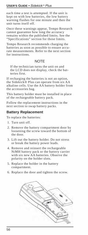
Battery ReplacementTo replace the batteries:
1. Turn unit off.
2. Remove the battery compartment door byloosening the screw toward the bottom ofthe door.
3. Lift out the battery holder. Do not stressor break the battery power leads.
4. Remove and reinsert the rechargeableNiMH battery pack or the battery carrierwith six new AA batteries. Observe thepolarity on the holder slots.
5. Replace the holder in the batterycompartment.
6. Replace the door and tighten the screw.
USER'S GUIDE • Sidekick Plus®
56

WASTE ELECTRONICELECTRICAL EQUIPMENTFor disassembly and disposal of electronicelectrical equipment, please refer to the website: www.tempo.textron.com
REPLACEMENT PARTSAND ACCESSORIESDo not attempt to replace or repair any of thecomponents inside the main body of theSidekick® Plus.
If your Sidekick® Plus requires service,please contact Tempo at 1-800-642-2155 forthe location of the nearest authorized repairand calibration facility.
The following list of user-replaceable partsand accessories for the Sidekick® Plus do notvoid the warranty:
1155-0521 AA cell battery pack
1155-0522 NiMH rechargeable batterypack
1155-0608 Replacement cord yellow/blue
119453701 AC/DC power supply
1155-0211 Battery door assembly
For replacement parts or accessories, contact:Tempo
Customer Service Department1390 Aspen WayVista, CA 92081
(760) 598-8900 or (800) 642-2155
or your local authorized Tempo distributor.
USER'S GUIDE • Sidekick Plus®
57
SPECIFICATIONS
SIDEKICK® PLUSDimensions: 279 x 121 x 76 mm (11 x 4.75 x3 in); 305 x 140 x 114 mm (12 x 5.5 x 4.5 in)(in soft case)
Weight: 1.4 kg (3 lb) (includes NiMH batterypack, soft case, and test leads)
Batteries: Tempo rechargeable battery pack(NiMH 6 cell) or 6 AA alkaline batteries
MEASUREMENTS
Volts AC• Range: 0 to 250 volts• Resolution: 0 to 9.99 V = 0.01 V;
10 to 300 V = 0.1 V• Accuracy: ±3%• Frequency response: 60 Hz
Volts DC• Range: 0 to 300 volts• Resolution: 0 to 9.99 V = 0.01 V;
10 to 300 V = 0.1 V• Accuracy: ±3%
Stress Test• Range: 0 to 82 dBrnC• Resolution: 0.1 dBrnC• Accuracy: ±5 dBrnC Overall; ±2 dBrnC
from 10 to 50 dBrnC• Longitudinal excitation: +90 dBrnC;
±6 dBrnC
Leakage• Range: 0 to 100 MΩ, autoranging• Resolution: 10 kΩ• Accuracy: ±3%
ResistanceRange: 0 to 100 MΩ, autoranging0 to 99 Ω
• Resolution: 0.1 Ω• Accuracy: ±3% or 1 Ω
1 kΩ to 100 MΩ• Resolution: 4 digits• Accuracy: ±3%
Distance to Open (Meter)Range: 0 to 18 km (0 to 60,000 feet)0 to 30 m (0 to 99 feet)
• Resolution: 0.3 m (1 foot)• Accuracy: 5%/0.6 m (5%/2 feet)
30 to 6095 m (100 to 19,999 feet)• Resolution: 4 digits• Accuracy: 4%
USER'S GUIDE • Sidekick Plus®
58
6096+ m (20,000+ feet)• Resolution: 4 digits• Accuracy: 10%
Loop Current• Range: 0 to 100 mA• Resolution: 0 to 9.99 mA = 0.01 mA;
10 to 100 mA = 0.1 mA• Accuracy: ±2 mA
Load CoilsLocates up to 4 load coils
Circuit Noise• Range: 0 to 90 dBrnC• Resolution: 0.1 dBrnC• Accuracy: ±2 dBrnC
Power Influence• Range: 40 to 100 dBrnC• Resolution: 0.1 dBrnC• Accuracy: ±2 dBrnC
Circuit Loss• Range: +3 to –45 dB• Resolution: 0.1 dB• Accuracy: ±0.5 dB
RFL• Distance measurement accuracy:
±0.5% of full scale, ±1 digit• Maximum fault resistance: 2 MΩ• Fault Check/Ohms Range: 0 to 19.99 MΩ• Distance Range:
0 to 61 km (0 to 199,999 feet)• Fault Current: 73 uA and 730 uA
depending on fault
Tone• Tracing Tone Generator (metallic
and common mode): 500 to 3500 Hz• Reference Tone: 3 to –20 dBm;
200 Hz to 20 kHz
TDRRange: 10 km (33 kilofeet)
Environmental• Operating Temperature:
–10 °C to 49 °C (14 °F to 120 °F)• Storage Temperature:
–18 °C to 49 °C (0 °F to 120 °F)
USER'S GUIDE • Sidekick Plus®
59
WARRANTY
GENERAL PROVISIONSSeller warrants to Buyer that products fur-nished hereunder will be merchantable, freefrom defects in design, material, and work-manship, fit and sufficient for the purposesintended by Buyer, free from all liens andencumbrances and will conform to and per-form in accordance with the specifications setforth in the Agreement for a period of OneYear, commencing with the date of accept-ance by Buyer.
Defective products will, at Buyer’s option, beeither returned to Seller, or Seller’sAuthorized Repair Agency, for repair orreplacement, with risk of in-transit loss anddamage borne and transportation charges paidby Seller, or repaired or replaced by Seller, orSeller’s Authorized Repair Agency, on site atSeller’s expense. Unless otherwise agreedupon by the parties, Seller, or Seller’sAuthorized Repair Agency, will completerepairs and ship the repaired product withinfive (5) days of receipt of the defective prod-uct or, at Buyer’s option, ship replacementproduct within five (5) days after receipt oforal notification from the Buyer. Seller, orSeller’s Authorized Repair Agency, will bearthe risk of in-transit loss and damage and willprepay and bear the cost of transportationcharges for shipments to Buyer of repaired orreplaced products. If requested by Buyer,Seller, or Seller’s Authorized Repair Agency,at Seller’s expense, will begin on-site repairswithin three (3) days after receiving verbalnotification from Buyer.
If product returned to Seller, or Seller’sAuthorized Repair Agency, or made availableto Seller, or Seller’s Authorized RepairAgency, on site for repair, as provided for inthis clause is determined to be beyond repair,Seller, or Seller’s Authorized Repair Agency,will promptly so notify Buyer and, unlessotherwise agreed to be the party.
Any replacement, repair, modification, instal-lation, or other service performed by Seller,or Seller’s Authorized Repair Agency, pur-suant hereto will be warranted as herein pro-vided based upon the date performance of theservices is completed and accepted by Buyerfor the remainder of the unexpired period ofthe original warranty or for a new period ofone (1) year, whichever is longer.
All services, if any, provided under thisAgreement will be provided in a fully profes-sional manner.
USER'S GUIDE • Sidekick Plus®
60
WORK HEREUNDERIt is understood that visits by representativesof Seller or its suppliers for inspection,adjustment or other similar purposes in con-nection with products purchased hereunderwill for all purposes be deemed “work here-under” and will be at no charge to Buyerunless otherwise agreed in writing withBuyer.
SPECIFIC WARRANTYPROVISIONS
Factory WarrantyTempo warrants all products against defectsin material or workmanship for a period ofone year from date of shipment to the originalpurchaser. All units returned to a Tempoauthorized repair center, delivery chargesprepaid, that are deemed defective under thiswarranty will be replaced or repaired atTempo’s option. This warranty shall not applyto any defect, failure, or damage caused byimproper use or inadequate maintenance. Thiswarranty does not apply to worn or damagedaccessories such as test leads, batteries, andsoft cases. Calibration is not covered underfactory warranty.
Product sold through distribution carries a15-month warranty due to turn-around time.
Contracted ServiceTempo offers contracted warranty for specificproducts. The Sales Department negotiatesthese contracts at the time of purchase. Suchcontracts are customer and/or marketingdriven. Contracts are product/customer spe-cific.
Extended WarrantyExtended warranty is available at the buyer’soption.
Warranty on Repaired ProductsTempo offers a 90-day warranty againstdefects in material or workmanship forrepaired products. Extended repair warrantymay be available for select customers and isnegotiated by sales department.
USER'S GUIDE • Sidekick Plus®
61

Flat Rate Repair ContractsFlat rate repair contracts for pricing and prod-uct coverage are available for non-warrantyrepairs. The sales department negotiates thesecontracts.
PCB (Module) ExchangeIt is the discretion of Tempo to exchangedefective or damaged PCB modules withrefurbished PCB modules.
Non-Warranty RepairsTempo will charge time and material for allproduct repairs that are non-warranty.
Any Tempo manufactured unit that isreceived with a broken seal (opened by some-one other than Tempo authorized personnel)will be considered non-warranty and repairedas such.
USER'S GUIDE • Sidekick Plus®
62