shri angalamman college of engineering and … sem/ce 1202... · shri angalamman college of...
TRANSCRIPT
SHRI ANGALAMMAN COLLEGE OF
ENGINEERING AND TECHNOLOGY
(An ISO 9001:2008 Certified Institution)
Siruganoor, Tiruchirappalli – 621 105.
(An ISO 9001:2008 Certified Institution)
Siruganoor, Tiruchirappalli – 621 105
DEPARTMENT OF CIVIL ENGINEERING
CE 1202 MECHANICS OF SOLIDS
UNIT – I
PART – A
1. Define (i) Poisson’s ration (ii) Shear modulus
2. Write down the relationship between E, K and Poisson’s ration.
3. Express the relationship among the three elastic constants.
4. Ina Mohr’s circle of stresses, what represents the maximum shear stress?
5. A rod of 2m long and 20mm diameter is subjected to an axial tensile load of 30KN. Find the
elongation of the rod along the axial direction. Assume the modulus of elasticity of the rod as 10 x
104 N/mm
2.
6. What do you mean by the term ‘principal stresses’?
7. Compare the stress – strain curve for mild steel.
8. A structural steel girder of span L has fixed ends. If the temperature increases by 20 C. What nature
of stress well be induced in the girder.
9. State Hooke’s law
10. How do you obtain the maximum shear stress by Mohr’s circle method?
11. What are the uses of Mohr’s circle?
12. Define: Principal stress and Principal plane
13. How will you differentiate elasticity and elastic limit?
14. Differentiate Ultimate stress and breaking stress.
15. What do you mean by rigid bodies?
PART – B
16. A 2m long steel bar is having uniform diameter of 40mm for a length of 1m, in the next 0.5m, its
diameter gradually reduces to‘d’ mm and for the remaining 0.5m. Length, diameter remains‘d’ mm
uniform. When a load of 300 KN was applied, the extension observed is equal to 5.78 mm.
Determine the diameter ‘d’ of the bar if E = 2 x 10⁵ N/mm
2.
17. At a certain point in a piece of elastic material. There are normal tensile stresses of magnitude 120
MPa and 60 MPa acting orthogonal to each other. In addition, there is a shearing stress of 80 MPa
acting normal to the normal stresses. Determine.
i) Magnitude and direction of the principal stresses
ii) Maximum shearing stress.
18. A steel bar 300mm long, 40mm wide and 25mm thick is subjected to a pull of 180KN. Determine the
change in volume of the bar. Take E = 2 x 10⁵ N/mm
2 and m = 4.
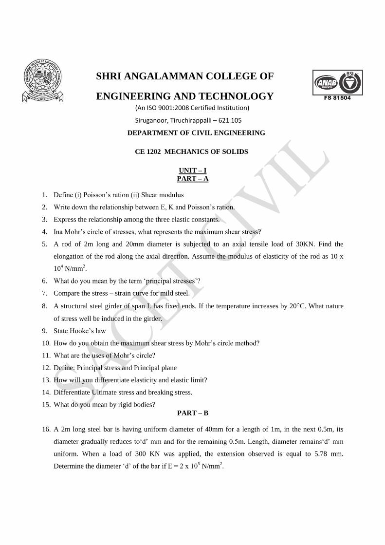
19. A steel bar 4.0 m long is acted upon by forces as shown in fig 1. Determine the total elongation of the
bar. Take E = 205 KN / mm2.
20. A bar 30mm in diameter was subjected a tensile load of 54KN and the measured extension on 300
mm gauge length was 0.112 mm and change in diameter was 0.00366 mm. Calculate poisson’s ratio
and the values of three module.
21. A 32mm steel rod is concentrically fixed is a brass tube which has the inside and outside diameters as
34mm and 48mm respectively. The length being equal to 400mm for both, the assembly is held
between two stoppers exactly at 400mm apart. If the temperature of the assembly is raised by 60 C,
find the stresses developed in the two materials, if
i) The distance between the stoppers remains constant and
ii) Increased by 0.25mm. Also find
iii) The increase in the distance between stoppers if a force of 80KN is exerted between them Es = 2 x
105 MPa, Eb = 0.9 x 10
5 MPa, s = 12 x 10
-6/ c and 6 = 21 x 10
-6/ c.
22. At a certain material under stress, the intensity of resultant stress on a plane is 65 MPa (tensile)
inclined at 30 to the normal to that plane. The stress on a plane at right angles to this plane has a
normal component of intensity 40 MPa (tensile). Find
i) The resultant stress on the second plane.
ii) The principal stresses a their planes of action
iii) Critical shear
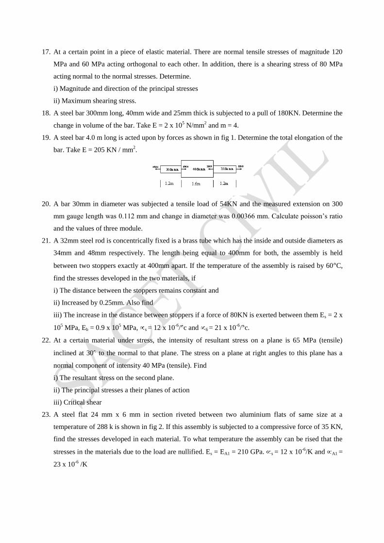
23. A steel flat 24 mm x 6 mm in section riveted between two aluminium flats of same size at a
temperature of 288 k is shown in fig 2. If this assembly is subjected to a compressive force of 35 KN,
find the stresses developed in each material. To what temperature the assembly can be rised that the
stresses in the materials due to the load are nullified. Es = EA1 = 210 GPa. s = 12 x 10-6
/K and A1 =
23 x 10-6
/K
24. A M.S Bar of 50 mm square in size and 150 mm long is subjected to an axial thrust of 200 KN. Half
the lateral strain is prevented by the application of uniform external pressure of certain intensity. If E
= 200 GPa and Poisson’s ration 0.3, Calculate the change in the length of the bar.
25. At a point in an elastic material under strain, there are normal stresses of 50N/mm2 respectively at
right angles to each other with a shearing stress of 25 N/mm2. Find the principal stresses and the
position of principal planes if
(a) 50 N/mm2 & 30N/mm
2 are tensile
(b) 50 N/mm2 is tensile & 30N/mm
2 is comp.
Find also the maximum shear stress and its plane in both the cases.
UNIT – II
PART – A
1. Define Tension coefficient?
2. When do you adopt method of sections?
3. What are the two types of trusses with respect to their joints?
4. How to increase the strength of the cylinder?
5. What is the basic difference in the skeleton of Pratt and How types of trusses?
6. The volumetric strain of a spherical shell is _________ that of the linear strain.
7. How do you solve statically indeterminate structures?
8. Is compound bar subjected to a qriel load a determinate structure? How?
9. State the condition for the stability of a plane truss
10. Mention the types of frames.
11. What are the types of trusses?
12. Define: Perfect frames.
13. Distinguish between cylindrical shell and spherical shell.
14. Write the difference between the thin cylinder and thick cylinder?
15. What are the assumptions made in finding out the forces in frame?
PART – B
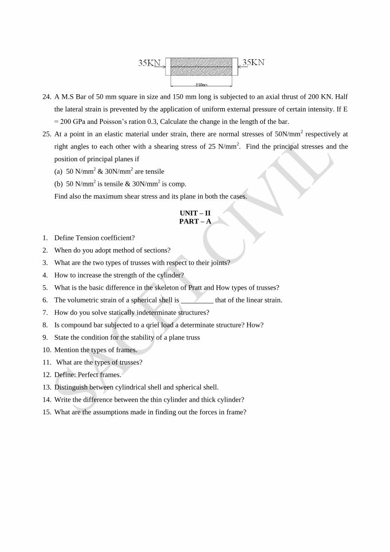
16. Find the forces in the members of the truss
17. Find the forces in the members AB, BF, BC and FE of the truss shown.
18. Find the forces in the members of the warren truss built of equilateral triangles.
19. The shell 3.25 m long, 1m dia, is under an internal pressure 1 MPa. If the thickness of the shell is
10mm. Find
i) hoop and longitudinal stresses
ii) maximum shear stress
iii) change in the dimensions.
E = 2 x 10⁵ MPa and poisons ratio 0.3
20. Compare and discuss the step by step procedures for the analysis of a truss by method of joints,
method of sections and by method of tension coefficients.
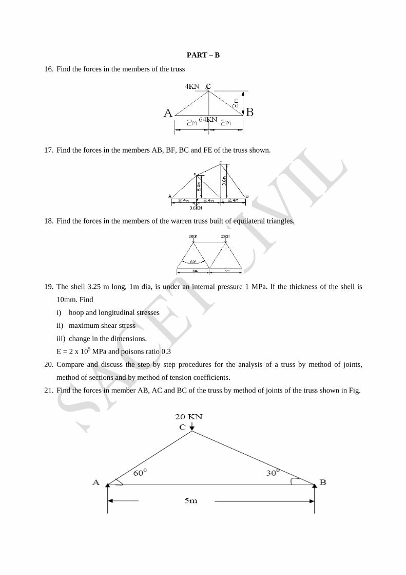
21. Find the forces in member AB, AC and BC of the truss by method of joints of the truss shown in Fig.
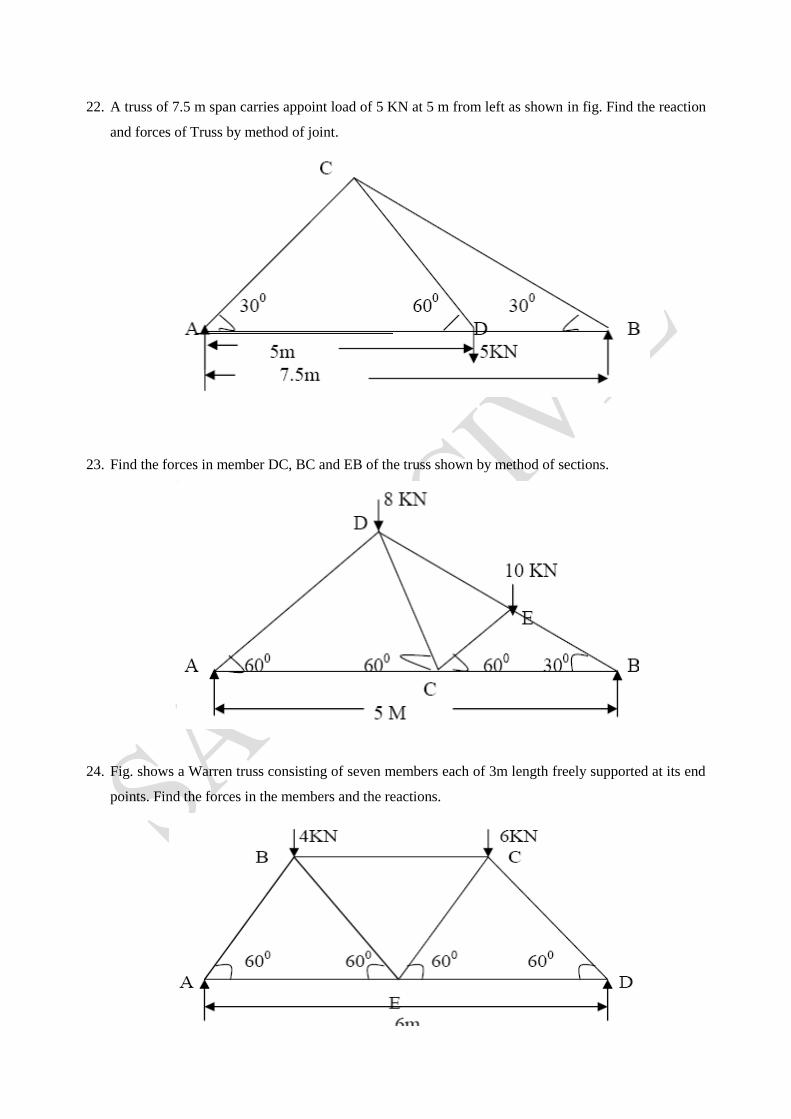
22. A truss of 7.5 m span carries appoint load of 5 KN at 5 m from left as shown in fig. Find the reaction
and forces of Truss by method of joint.
23. Find the forces in member DC, BC and EB of the truss shown by method of sections.
24. Fig. shows a Warren truss consisting of seven members each of 3m length freely supported at its end
points. Find the forces in the members and the reactions.
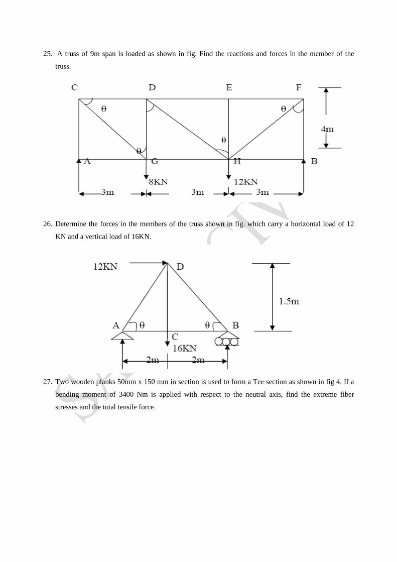
25. A truss of 9m span is loaded as shown in fig. Find the reactions and forces in the member of the
truss.
26. Determine the forces in the members of the truss shown in fig. which carry a horizontal load of 12
KN and a vertical load of 16KN.
27. Two wooden planks 50mm x 150 mm in section is used to form a Tee section as shown in fig 4. If a
bending moment of 3400 Nm is applied with respect to the neutral axis, find the extreme fiber
stresses and the total tensile force.
UNIT – III
PART – A
1. Write down the relationship between intensity of loading, S.F and B.M
2. What are guided supports?
3. Draw the shear force and bending moment diagrams for the beam shown in fig.
4.
5. What do you mean by sagging bending moment and hogging bending moment?
6. What is the least internal radius to which a bar of steel 100mm wide and 10mm thick can be bent so
that the maximum stress will not exceed 500 N/mm2. Assume the modulus of elasticity of steel as 2 x
105 N/mm2.
7. Draw the bending stress distribution for a symmetrical I Section.
8. Relate the rate of loading, shear force, bending moment, slope and deflection by integral equations.
9. What are shear force and bending moment?
10. State the relationship between the average shear stress and maximum shear stress in a rectangular
beam.
11. What is uniformly distributed load and uniformly varying load?
12. What are determinate structures?
13. What are the equilibrium equations?
14. What is point of contraflexure?
15. What are the assumptions made in theory of simple bending?
16. Write the theory of simple bending equation.
PART – B
17. Compare and discuss the step by step procedures for the analysis of a truss by method of joints,
method of sections and by method of tension coefficients.
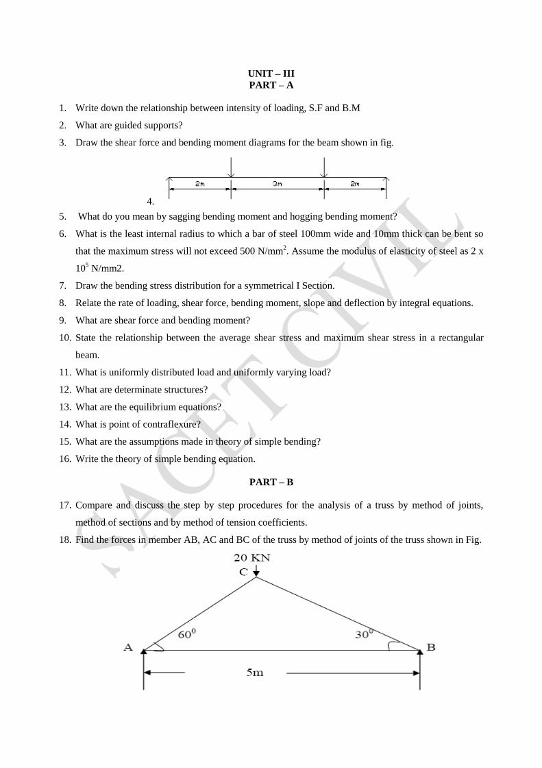
18. Find the forces in member AB, AC and BC of the truss by method of joints of the truss shown in Fig.
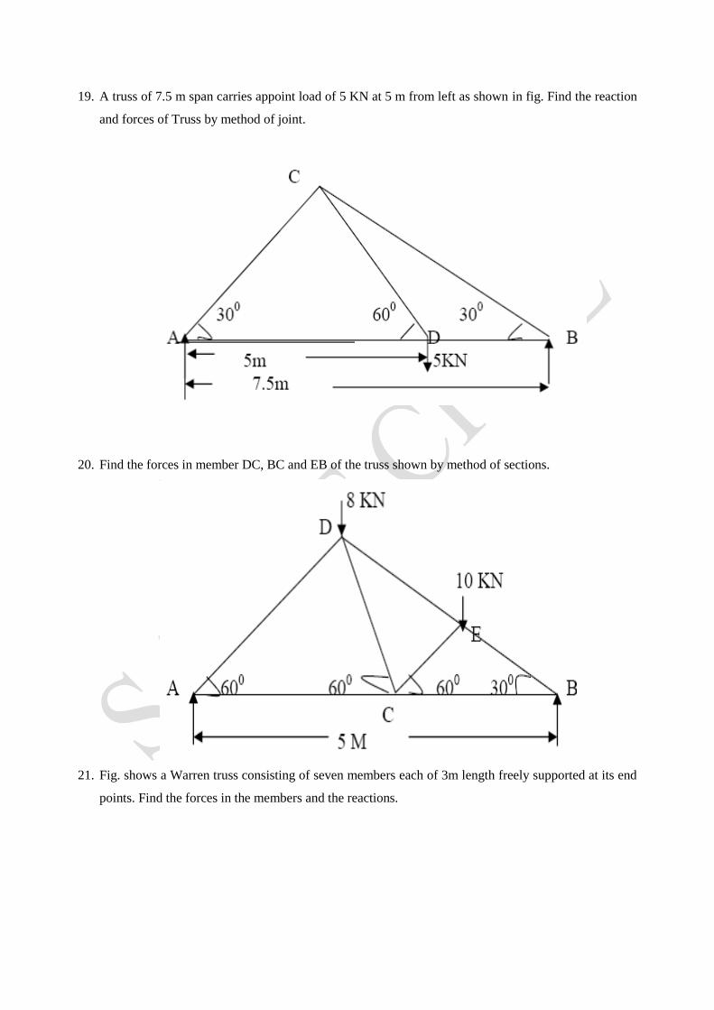
19. A truss of 7.5 m span carries appoint load of 5 KN at 5 m from left as shown in fig. Find the reaction
and forces of Truss by method of joint.
20. Find the forces in member DC, BC and EB of the truss shown by method of sections.
21. Fig. shows a Warren truss consisting of seven members each of 3m length freely supported at its end
points. Find the forces in the members and the reactions.

22. A truss of 9m span is loaded as shown in fig. Find the reactions and forces in the member of the
truss.
23. Determine the forces in the members of the truss shown in fig. which carry a horizontal load of 12
KN and a vertical load of 16KN.
24. Two wooden planks 50mm x 150 mm in section is used to form a Tee section as shown in fig 4. If a
bending moment of 3400 Nm is applied with respect to the neutral axis, find the extreme fiber
stresses and the total tensile force.
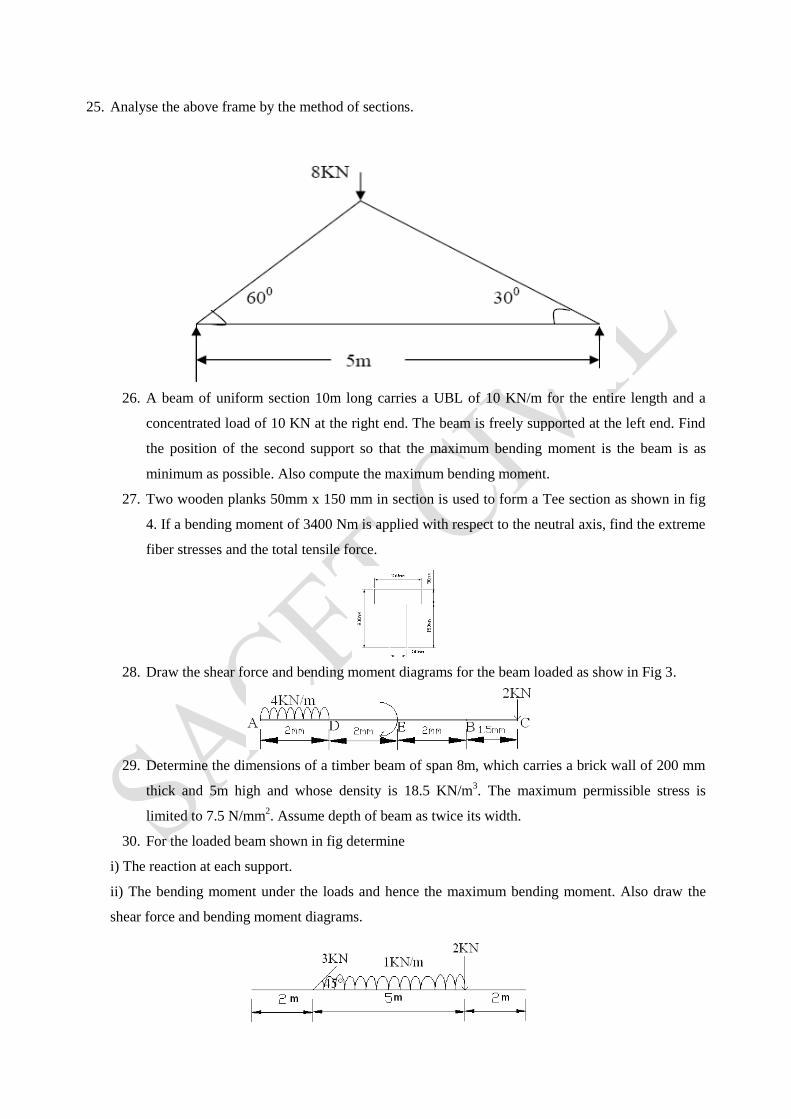
25. Analyse the above frame by the method of sections.
26. A beam of uniform section 10m long carries a UBL of 10 KN/m for the entire length and a
concentrated load of 10 KN at the right end. The beam is freely supported at the left end. Find
the position of the second support so that the maximum bending moment is the beam is as
minimum as possible. Also compute the maximum bending moment.
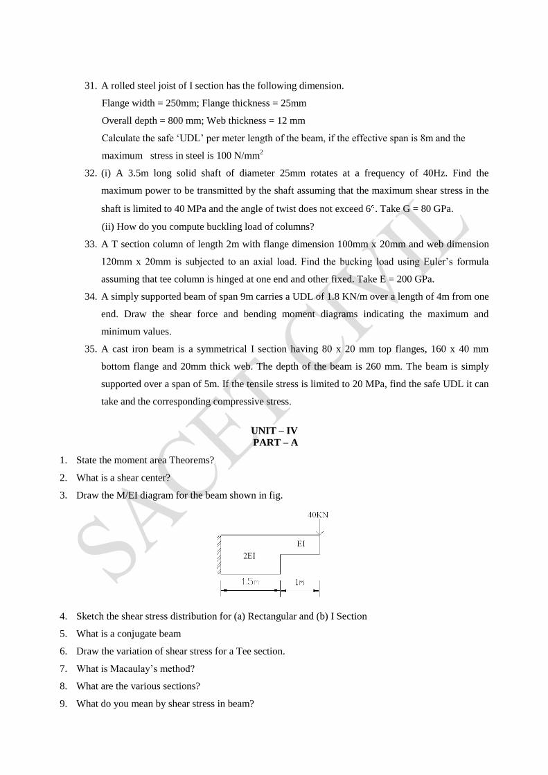
27. Two wooden planks 50mm x 150 mm in section is used to form a Tee section as shown in fig
4. If a bending moment of 3400 Nm is applied with respect to the neutral axis, find the extreme
fiber stresses and the total tensile force.
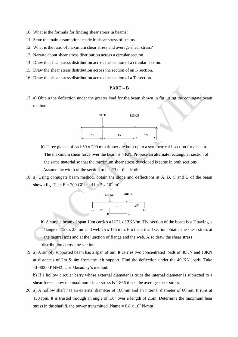
28. Draw the shear force and bending moment diagrams for the beam loaded as show in Fig 3.
29. Determine the dimensions of a timber beam of span 8m, which carries a brick wall of 200 mm
thick and 5m high and whose density is 18.5 KN/m3. The maximum permissible stress is
limited to 7.5 N/mm2. Assume depth of beam as twice its width.
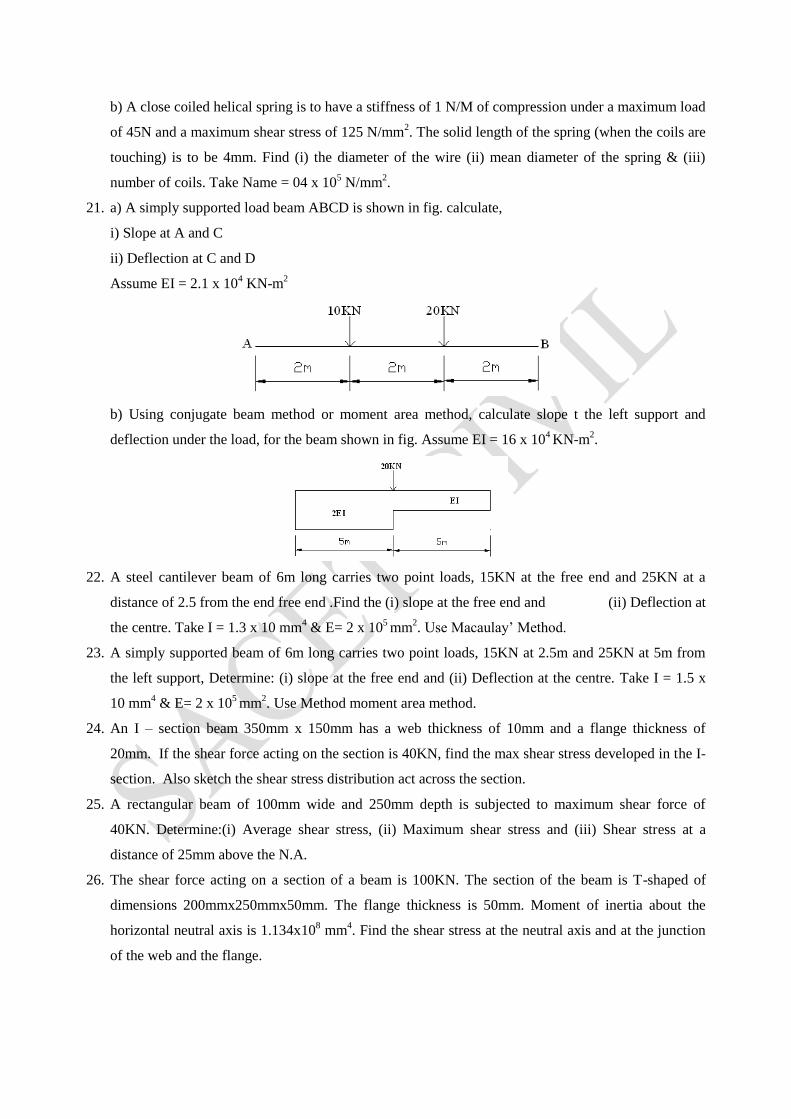
30. For the loaded beam shown in fig determine
i) The reaction at each support.
ii) The bending moment under the loads and hence the maximum bending moment. Also draw the
shear force and bending moment diagrams.
31. A rolled steel joist of I section has the following dimension.
Flange width = 250mm; Flange thickness = 25mm
Overall depth = 800 mm; Web thickness = 12 mm
Calculate the safe ‘UDL’ per meter length of the beam, if the effective span is 8m and the
maximum stress in steel is 100 N/mm2
32. (i) A 3.5m long solid shaft of diameter 25mm rotates at a frequency of 40Hz. Find the
maximum power to be transmitted by the shaft assuming that the maximum shear stress in the
shaft is limited to 40 MPa and the angle of twist does not exceed 6 . Take G = 80 GPa.
(ii) How do you compute buckling load of columns?
33. A T section column of length 2m with flange dimension 100mm x 20mm and web dimension
120mm x 20mm is subjected to an axial load. Find the bucking load using Euler’s formula
assuming that tee column is hinged at one end and other fixed. Take E = 200 GPa.
34. A simply supported beam of span 9m carries a UDL of 1.8 KN/m over a length of 4m from one
end. Draw the shear force and bending moment diagrams indicating the maximum and
minimum values.
35. A cast iron beam is a symmetrical I section having 80 x 20 mm top flanges, 160 x 40 mm
bottom flange and 20mm thick web. The depth of the beam is 260 mm. The beam is simply
supported over a span of 5m. If the tensile stress is limited to 20 MPa, find the safe UDL it can
take and the corresponding compressive stress.
UNIT – IV
PART – A
1. State the moment area Theorems?
2. What is a shear center?
3. Draw the M/EI diagram for the beam shown in fig.
4. Sketch the shear stress distribution for (a) Rectangular and (b) I Section
5. What is a conjugate beam
6. Draw the variation of shear stress for a Tee section.
7. What is Macaulay’s method?
8. What are the various sections?
9. What do you mean by shear stress in beam?
10. What is the formula for finding shear stress in beams?
11. State the main assumptions made in shear stress of beams.
12. What is the ratio of maximum shear stress and average shear stress?
13. Narrate about shear stress distribution across a circular section.
14. Draw the shear stress distribution across the section of a circular section.
15. Draw the shear stress distribution across the section of an I- section.
16. Draw the shear stress distribution across the section of a T- section.
PART – B
17. a) Obtain the deflection under the greater load for the beam shown in fig. using the conjugate beam
method.
b) Three planks of each50 x 200 mm timber are built up to a symmetrical I section for a beam.
The maximum shear force over the beam is 4 KN. Propose an alternate rectangular section of
the same material so that the maximum shear stress developed is same in both sections.
Assume the width of the section to be 2/3 of the depth.
18. a) Using conjugate beam method, obtain the slope and deflections at A, B, C and D of the beam
shown fig. Take E = 200 GPa and I = 2 x 10⁻²
m4
b) A simple beam of span 10m carries a UDL of 3KN/m. The section of the beam is a T having a
flange of 125 x 25 mm and web 25 x 175 mm. Fro the critical section obtains the shear stress at
the neutral axis and at the junction of flange and the web. Also draw the shear stress
distribution across the section.
19. a) A simply supported beam has a span of 6m. It carries two concentrated loads of 40KN and 10KN
at distances of 2m & 4m from the left support. Find the deflection under the 40 KN loads. Take
EI=8000 KNM2. Use Macaulay’s method.
b) If a hollow circular berry whose external diameter is truce the internal diameter is subjected to a
shear force, show the maximum shear stress is 1.866 times the average shear stress.
20. a) A hollow shaft has an external diameter of 100mm and an internal diameter of 60mm. It runs at
130 rpm. It is trusted through an angle of 1.8 over a length of 2.5m. Determine the maximum hear
stress in the shaft & the power transmitted. Name = 0.8 x 10⁵ N/mm
2.
b) A close coiled helical spring is to have a stiffness of 1 N/M of compression under a maximum load
of 45N and a maximum shear stress of 125 N/mm2. The solid length of the spring (when the coils are
touching) is to be 4mm. Find (i) the diameter of the wire (ii) mean diameter of the spring & (iii)
number of coils. Take Name = 04 x 105 N/mm
2.
21. a) A simply supported load beam ABCD is shown in fig. calculate,
i) Slope at A and C
ii) Deflection at C and D
Assume EI = 2.1 x 10⁴ KN-m
2
b) Using conjugate beam method or moment area method, calculate slope t the left support and
deflection under the load, for the beam shown in fig. Assume EI = 16 x 104 KN-m
2.
22. A steel cantilever beam of 6m long carries two point loads, 15KN at the free end and 25KN at a
distance of 2.5 from the end free end .Find the (i) slope at the free end and (ii) Deflection at
the centre. Take I = 1.3 x 10 mm4 & E= 2 x 10
5 mm
2. Use Macaulay’ Method.
23. A simply supported beam of 6m long carries two point loads, 15KN at 2.5m and 25KN at 5m from
the left support, Determine: (i) slope at the free end and (ii) Deflection at the centre. Take I = 1.5 x
10 mm4 & E= 2 x 10
5 mm
2. Use Method moment area method.
24. An I – section beam 350mm x 150mm has a web thickness of 10mm and a flange thickness of
20mm. If the shear force acting on the section is 40KN, find the max shear stress developed in the I-
section. Also sketch the shear stress distribution act across the section.
25. A rectangular beam of 100mm wide and 250mm depth is subjected to maximum shear force of
40KN. Determine:(i) Average shear stress, (ii) Maximum shear stress and (iii) Shear stress at a
distance of 25mm above the N.A.
26. The shear force acting on a section of a beam is 100KN. The section of the beam is T-shaped of
dimensions 200mmx250mmx50mm. The flange thickness is 50mm. Moment of inertia about the
horizontal neutral axis is 1.134x108 mm
4. Find the shear stress at the neutral axis and at the junction
of the web and the flange.
UNIT – V PART – A
1. Draw the shear stress variation of a circular section?
2. What is a leaf spring?
3. For same weight, which shaft will carry more torque, a solid one or a hollow one? Why?
4. How does the shear stress vary across a solid shaft?
5. What is a stepped shaft?
6. Compare close coiled and open coiled springs are the action of an axial load.
7. State Mohr’s Theorems?
8. Define proof resilience and what is its magnitude?
9. What is stiffness of the spring? Give its unit.
10. Find the tongue which a shaft of 100 mm diameter cent transmit safely, if the sheer stress not to
exceed 100 N/mm
11. What are the types of springs?
12. What is solid length?
13. Define stiffness.
14. Differentiae between open and closed coil helical spring.
15. Define torsional rigidity.
PART – B
1. A steel shaft ABCD having a total length of 2400 mm is contributed by three different sections as
Follow. The portion AB is hollow having outside and inside diameters 80mm and 50mm
respectively, BC is solid and 80 mm diameter. CD is also solid and 70mm in diameter. If the angle is
twist is same for each section, determine the length of each portion and the total angle of twist.
Maximum permissible shear stress is 50MPa and shear Modulus 0.82 x 10⁵ MPa.
2. It is required to design a close coiled helical spring which shall deflect 1mm under an axial load of
100N at a shear stress of 90 MPa. The spring is to be Made of round wire having shear Modulus of
0.8 x 10⁵ MPa. The Mean diameter of the coil wire. Find the diameter and length of the wire.
3. A solid circular shaft transmits 294KN at 300 rpm. If the maximum shear stress should be less than
42 MPa and angle of twist in the length of 3m should not exceed 1 , find the diameter of the shaft.
Take G = 80 G Pa.
4. A close coiled helical spring of 100 mm mean diameter is made up of 10mm diameter rod and has 20
turns. The spring carries an axial load of 200N. Determine the shearing stress and the deflection
developed in the spring. Also find the stiffness of the spring. Take G = 84 GPa
5. At a point in a bracket the stresses on two mutually planes are 650 N/mm2 tensile and 400 N/mm
2
Compressive. The shear stress across then plane sis 100 N/mm2. Find the principal planes, principal
stresses and maximum shear stress.
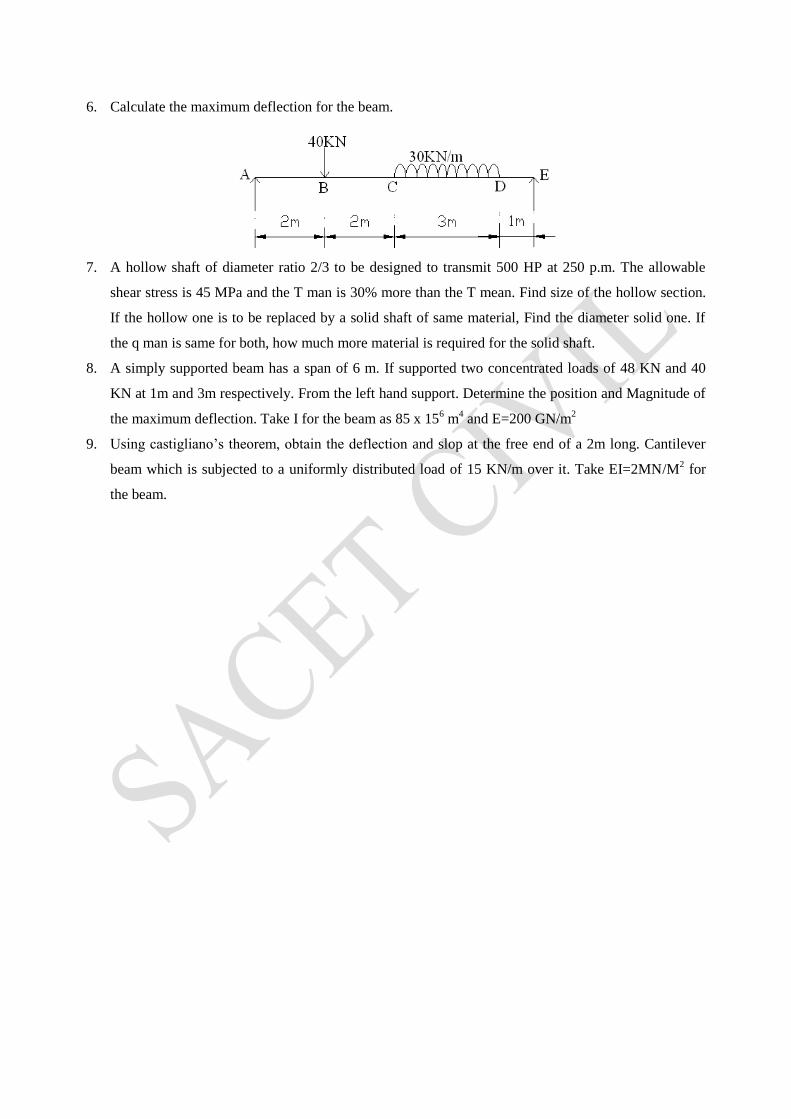
6. Calculate the maximum deflection for the beam.
7. A hollow shaft of diameter ratio 2/3 to be designed to transmit 500 HP at 250 p.m. The allowable
shear stress is 45 MPa and the T man is 30% more than the T mean. Find size of the hollow section.
If the hollow one is to be replaced by a solid shaft of same material, Find the diameter solid one. If
the q man is same for both, how much more material is required for the solid shaft.
8. A simply supported beam has a span of 6 m. If supported two concentrated loads of 48 KN and 40
KN at 1m and 3m respectively. From the left hand support. Determine the position and Magnitude of
the maximum deflection. Take I for the beam as 85 x 156 m
4 and E=200 GN/m
2
9. Using castigliano’s theorem, obtain the deflection and slop at the free end of a 2m long. Cantilever
beam which is subjected to a uniformly distributed load of 15 KN/m over it. Take EI=2MN/M2 for
the beam.