shortwave - americanradiohistory.com · shortwave al vol x111 february, 1956 number 12. the short...
TRANSCRIPT

SHORTWAVEal
VOL X111 FEBRUARY, 1956 NUMBER 12
THE SHORT WAVE MAGAZINE February, 1956
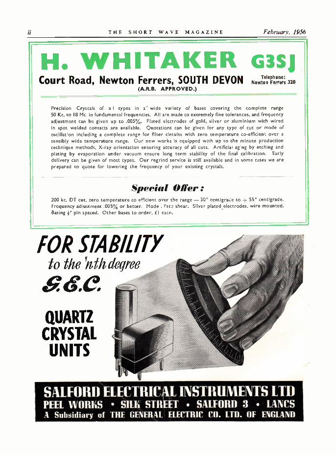
H. WHITAKER G3SJCourt Road, Newton Ferrers, SOUTH DEVON Telhone:
NewtoneFerrers320(A.R.B. APPROVED.)
Precision Crystals of a I types in a` wide variety of bases covering the complete range
50 Kc. to 18 Mc. in fundamental frequencies. All are made to extremely fine tolerances, and frequencyadjustment can be given up to .005%. Plated electrodes of gold, silver or aluminium with wiredin spot welded contacts are available. Quotations can be given for any type of cut or mode ofoscillat on including a complete range for filter circuits with zero temperature co -efficient over asensibly wide temperature range. Our new works is equipped with up to the minute productiontechnique methods, X-ray orientation ensuring accuracy of all cuts. Artificial ag'ng by etching andplating by evaporation under vacuum ensure long term stability of the final calibration. Earlydelivery can be given of most types. Our regrind service is still available and in some cases we areprepared to quote for lowering the frequency of your existing crystals.
Special Offer:200 kc. DT cut, zero temperature co efficient over the range - 30° centigrade to -{- 55° centigrade.Frequency adjustment .005% or better. Mode . Faca shear. Silver plated _electrodes, wire mounted.Basing f" pin spaced. Other bases to order, £I each.
FOR STABILITYto the 'nth degree
QUARTZ
CRYSTALUNITS
SALFORD ELECTRICAL INSTRUMENTS LTDPEEL WORKS SILK STREET SALFORD 3 LANCSA Subsidiary of THE GENERAL ELECTRIC CO. LTD. OF ENGLAND
Volume X111 THE SHORT VI: VE MAGAZINE 617
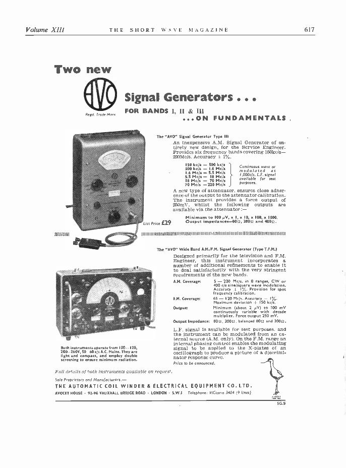
Two new
Regd. Trade Mark
111111111111111111
Signal Generators ..FOR BANDS I, II & HI
...ON FUNDAMENTALS
Both instruments operate from 100--I20,200-260V, SO 60 c/s A.C. Mains. They arelight and compact, and employ doublescreening to ensure minimum radiation.
List Price £29
The "AYO" Signal Generator Type IllAn inexpensive A.M. Signal Generator of en-tirely new design, for the Service Engineer.Provides six frequency bands covering 150kc/s-220Mc/s. Accuracy E 1%.
150 kc/s - 500 kc/s500 kc/s - 1.6 Mc/s1.6 Mc/s - 5.5 Mc/s5.5 Mc/s - 18 Mc/s18 Mc/s - 70 Mc/s70 Mc/s -220 Mc/s
A new type of attenuator, ensures close adher-ence of the output to the attenuator calibration.The instrument provides a force output of250mV, whilst the following outputs areavailable via the attenuator :-
Minimum to IOO µV, x I, x 10, x 100, x 1000.Output impedances -8012, 2000 and 4000.
Continuous wave ormodulated at1.000c/s. L.F. signalavailable for testpurposes.
The "AYO" Wide Band A.M./F.M. Signal Generator (Type T.F.M.)
Designed primarily for the television and F.M.Engineer, this instrument incorporates anumber of additional refinements to enable itto deal satisfactorily with the very stringentrequirements of the new bands.A.M. Coverage:
F.M. Coverage:
Output:
Output Impedance:
5 - 220 Mc/s. in 8 ranges, CW or400 c/s sine/square wave modulation.Accuracy - 1%. Provision for spotfrequency calibration.65 - 120 Mc/s. Accuracy a 1%.Maximum deviation i_ 150 kc/s.Minimum (about 2 µV) to 100 mVcontinuously variable with decademultiplier. Force output 250 mV.800, 2000, balanced 800 and 3000.
L.F. signal is available for test purposes. andthe instrument can be modulated from an ex-ternal source (A.M. only). On the F.M. range aninternal phasing control enables the modulatingsignal to be applied to the X -plates of anoscillograph to produce a picture of a discrimi-nator response curve.Price to be announced.
Full details of both instruments available on request.
Sole Proprietors and Manufacturers:-
THE AUTOMATIC COIL WINDER & ELECTRICAL EQUIPMENT CO. LTD.AVOCET HOUSE 92-96 VAUXHALL BRIDGE ROAD . LONDON S.W.I Telephone: VICtoria 3404 (9 lines)
50.5
618 THE SHORT WAVE MAGAZINE February, 1956
TECHNICAL PUBLICATIONSAVAILABLE FROM STOCK
Post FreeSINGLE SIDEBAND TECHNIQUES 14s. 6d.SINGLE SIDEBAND FOR THE RADIO AMATEUR I4s. 6d.HINTS AND KINKS, Vol. 5 lls. Od.ANTENNA HANDBOOK (7th Edition) 19s. Od.ANTENNA MANUAL 28s. Od.A COURSE IN RADIO FUNDAMENTALS (New Edition) 10s. 6d.HOW TO BECOME A RADIO AMATEUR (Published by ARRL) 5s. Od.LEARNING THE RADIO TELEGRAPH CODE 4s. 6d.SURPLUS CONVERSION MANUAL Vol. 1 21s. Od.
Vol. 2 21s. Od.MOBILE HANDBOOK (Published by CQ) 17s. 6d.MODEL CONTROL BY RADIO 8s. 6d.HIGH-FIDELITY TECHNIQUES 8s. 6d.HIGH-FIDELITY 12s. 6d.BASIC RADIO COURSE 19s. Od.PRACTICAL DISC RECORDING 6s. 6d.RADIO AND TV HINTS 8s. 6d.TRANSISTORS - THEORY AND PRACTICE 16s. 6d.OSCILLOSCOPE, Techniques and Applications 18s. 6d.UHF ANTENNAS, CONVERTERS AND TUNERS Its. Od.MOBILE MANUAL (The new one published by ARRL) 22s. Od.OPERATING AN AMATEUR RADIO STATION 2s. 8d.
(Published by ARRL)
WORLD RADIO HANDBOOK1956 Edition 11/- Post Free
THE RADIO HANDBOOK (14th Edition)American, Published by " Editors and Engineers," 768 pages available February 60/- Post Free
RADIO AMATEUR CALL BOOKWinter 1955/6 Edition
Abridged Edition excludes only American amateur stations. Otherwise complete with latest call sign -address listings for all countries, and including much DX data. In its 33rd year of publication.Abridged Edition Price 15s. Post freeComplete Edition Price 31s. Post free
WORLD RADIO VALVE HANDBOOKSpecial Offer. (Reduced from IIs. 10d. Limited supply). Price 5s. 10d. Post free
THE RADIO AMATEUR'S HANDBOOK(Published by A.R.R.L.)
1956 Edition, 600 pages, available March Price 32s. Post free
MAGAZINES BY SUBSCRIPTIONOne Yea, One Year
TELEVISION 485. Od. SERVICE 24s. Od.TELEVISION ENGINEERING ..... 325. Od. F.M. AND TELEVÍSION ......... .... .. 32s. Od.CQ, Radio Amateur's Journal 44s. Od. ELECTRONICS (Trade only) I60s. Od.AUDIO 40s. Od. POPULAR SCIENCE 45s. Od.RADIO AND TELEVISION NEWS 365. Od.
D, O 33s. OdRADIO EL 33s. Od. Subscription Service 'or All American Radio and TechnicalRAPOPULAR MECHANICS 32s. Od. Periodicals.
SHORT WAVE MAGAZINE(PUBLICATIONS DEPARTMEN7)
55 VICTORIA STREET LONDON S.W.1 ABBEY 5341
Volume XIII THE SHORT WAVE MAGAZINE 619
CALLING S.W. ENTHUSIASTSCOURSES FOR RADIO AMATEURS EXAMS AND P.M.G. Ist & 2nd
CLASS CERTIFICATES (THEORY). ALSO GENERAL COURSES FOR S.W. LISTENERS
Take our special postal courses which have beenwritten by experts both in these subjects and inmodern methods of postal instruction. E.M.I.INSTITUTES are part of a world-wide elec-tronics organisation, and many former studentstestify that our tuition was invaluable in ensuring
their success in examinations.
POST THIS COUPON TODAY
SPECIAL PRACTICAL KITSare available as part of our Radio Courses. Atypical course for beginners covers the design,construction and operation of a short wave2 valve receiver. This
equipment is suppliedupon enrolment, and
remains your property.
To E.M.I. INSTITUTES, Dept. 14 R, 43 Grove Park Rd., London, W.4.
Subject(s) of interest
Name
Address
FEB
II llc,I''
E.M.I.INSTITUTES
An educational organisation associated with the E.M.I. Group ofCompanies which include "HIS MASTERS VOICE,"
MARCONIPHONE. ETC. í.c.43
A GUIDE TO THE LARGESTAND MOST VARIED STOCK
AT WEBB'SEDDYSTONERECEIVERSFROM STOCK
680X ...750 ...
840A ...
C120
C78
C55
Extended "easy"payments arranged on
any apparatus totalling£15 or more
Webb's Radio is almost onthe corner of Oxford Streetand Soho Street-first onthe left from Charing CrossRoad end of Oxford Street.Nearest Tube Station :Tottenham Court Road.
MAIN LONDON DEALERSFOR EDDYSTONE
The complete range alwaysavailable from stock. Phone
Small components ingreat variety by
BULGIN - ERIE -WELWYN- T.C.C. - COLVERN -WODEN - WEARITE -DUBILIER - BELLING& LEE - EDDYSTONE
and all that is Best inBritish Manufacture
Our Service Departmentspecialises in the renova-tion and re -alignmentof communicationsreceivers.
iVi9 :1±14 SOHO ST., OXFORD ST., LONDON, W.I.
GERrard 2089. Shop Hours : 9 a.m.-5 30 p.m. (7 p.m. Thursdays) and 9 a.m.-I p.m. Sots.

THE SHORT WAVE MAGAZINE February, 1956
QY3-65V.H.F. 1101ÍIlER TETRODE
i ,/
- a% `LG' J e,/i.toapU". G ,-,
This new tetrod:, t:;e QY3-65, embodies a similar technique and construction to the Mullard rangeof all -glass transmitting valves which are already well established in communications and industry.It has an anode dissipation of 65 watts and a maximum frequency of 250 Mc;'s and is directly inter-changeable with the American 4-65A.Relatively high outputs can be obtained from the QY3-65 at low anode voltages, and its quick heatingfilament allows power consumption during standby to be reduced to a minimum.Write for detailed information on this valve, rower triodes and other tetrodes made by Mullard.
MAXIMUM OPERATING CONDITIONS (CLASS C AMPLIFIER) AT SO Mcls MaximumFrequency at
reduced ratings(Mc s)Valve Type
Va(V)
V81(V)
la(mA)
lei(mA)
Vin (peak)(V)
Pload(W)
n
QY3-65(CV1905) TETRODE 3000 -100 115 10 170 224 81 250
TY2-125 (CV1924) TRIODE 2500 -200 205 40 390 310 76 200
QY3-125 (CV2130) TETRODE 3000 -ISO 167 6.5 300 300 75 200
QY4-250 (CV2131) TETRODE 4000 -225 312 9 374 800 80 1:0
Mullard MULLARD LTD., COMMUNICATIONS & INDUSTRIAL VALVE DEPT., 1111
CENTURY HOUSE, SHAFTESBURY AVENUE, LONDON, WC2
M VT 184A

INDEX TOADVERTISERS SHORT WAVE
PAGE
Altham Radio... ... ... 671 MAGAZINEAnglin ... ... ... ... 668
VOL. XIII FEBRUARY 1956 No. 150Automatic Coil 617
Brookes Crystals, Ltd. cover iii CONTENTSPage
Brown, S. G. ... ... ... 622Editorial 623
Candler System 669 The "Trojan" Modulator, by J. N. Walker (G5JU) ... .. ... 625
619The N.Z. ZC1 Mk II for Portable Operation
E.M.I. Institutes by C. R. Plant (G5CP) 635
Harris, P. ... ... ... 670 DX Commentary, by L. H. Thomas, M.B.E. (G6Q131 .. .. 640
Remote Comfort, by G3COI ... 646Henley's ... ... ... 622
Going After DX, Part III, by The Old Timer ... 648
Henry's ... cover iv Adjustment of Overtone Crystal Oscillators,by I. A. Bladon, B.Sc. (G3FDU) ... 650
Home Radio ... ... 622VHF Bands, by A. I. Devon ... 652
Labgear ... 669 - cover iii Amateur Radio for The Beginner, Part XI :" Principles of Modulation (2)," by A. A. Mawse 657
Lyons Radio ... ... 669 The Low -C Colpitts Oscillator,by F. W. Buckland, A.M.Brit.I.R.E. (G3DIR) ... .. ... 661
Mullard ... 620 The Other Man's Station - G3DGN ... 663
Proops ... 670 New QTH's ... 664
The Month with The Clubs - From Reports ... 665Rollet, H. ... ... ... 672
Nuts on DX 667
Salford ... ... ... cover iiManaging Editor : AUSTIN FORSYTH, O.B.E. (G6FO)
Small Advertisements 669-672 Advertisement Manager : P. H. FALKNER
Southern Radio 671 Assistant Editor : L. H. THOMAS, M.B.E. (G6QB)
Published the Friday following the first Wednesday each month at 55 VictoriaS.W.M. Publications Dept. 618 Street, London, S. W.1. Telephone : Abbey 5341/2
Annual Subscription : Home and Overseas 24s. post paid.
Copyright Reserved throughout the World.
AUTHORS' MSSArticles submitted for Editorial consideration must be typed double-spacedwith wide margins on one side only of quarto or foolscap sheets, with diagramsshown separately. Photographs should be clearly identified on the back.Payment is made for all material used, and it is a condition of acceptancethat full copyright passes to the Short Wave Magazine, Ltd., on publication.
Universal Electronics ... 668
Webb's Radio 619
Whitaker cover ii
Young ... ... cover iii

622 THE SHORT WAVE MAGAZINE February, 1956
THE
INSTRUMENT
ai.MODELSpecially designed forsoldering operations inthe compact assembliesused in present dayradio, televisionand electronicindustries.Weight 31 oz.excludingflexible.Length 9i n.25 WattsVoltage range
12, 24, 5024/- each
100-I10,120-130,200-220220-24022/- each
a
Interestingfeatures
I. Bit " diameter,simple to replace.
2. Steel cased elementalso replaceable.
3. Detachable hook forsuspending iron when notin use.
4. Moulded two part handle,remains cool in use.
5. Six ft. Henley Flexible.
jEN LE'IUD! MAI
ELECTRICSOLDERING IRONS
W. T. HENLEY'S TELEGRAPH WORKS CO. LTD.
51/53, Hatton Garden, London, E.C.I.
127"%
% .(6.3rownand now:
S. G. Brown provideHeadphones and assoc-iated equipment for allknown purposes.Brochure " S " sent onrequest.
HEADPHONESFOR MARINEEQUIPMENT
Every seagoingvessel in thiselectronic agerelies on MarineCommunicationEquipment.
Our contributionis a specialised
range of reliableHeadphones which
provide ships' opera-tors with the clearest
possible reception of allsignals-Morse or speech.
SHAKESPEARE STREET, WATFORD, HERTSTelephone : Watford 7241
(I)
HOME R4 D10 OF MITCHAMFOR
RDYSTONERECEIVERS and COMPONENTS
All Eddystone components are in stock and fullyillustrated catalogue is available price 1/ -
SPECIAL OFFERST.C.C. 16mfd 375 volts can type condensers. 41 in.high 11 in.dia. BRAND NEW 2/-each.
COSSOR SI30P voltage regulators (CV45) stabilise at130 volts. Strike at 135v. BRAND NEW 3/- each.
JACKSON C804 25pf air -spaced tuning condenserin. spindle and ceramic insulation 2/6d. each.
Please add postage.
All components in stock for the MULLARD FM TUNERMULLARD FIVE -TEN AMPLIFIER, G.E.C. 912, JASONFM TUNER, TELETRON BAND III CONVERTERS,
ETC.
HOME R4D/0187, LONDON ROAD, MITCHAM, SURREY.
MIT. 3282
FOR THE EXPERIMENTER AND THE RADIO ENGINEER
11ORTItiAVE
EDITORIAL
Evolution theresince communication by wireless became a practicable proposition,
there has always been a strong body of professional opinion -sustained by mathematical argument - holding that wavelengths shorter than those in generaluse at any given period were suitable only for line -of -sight working. On this assumption,great decisions have been taken, based upon pure theory with no shadow of experimentalproof to support it.
This same argument about line -of -sight paths has, in fact, been heard ever since Marconiproduced his first results, and he was the first practical radio engineer to challenge it. In ourown time, it will be within the recollection of many reading these lines that " wavelengthsbelow 200 metres " were given over to the radio amateurs of the early 1920's because theywere considered useless for any commercial purpose. It is well within the knowledge of mostreaders that even since the last War there has been a general tendency among the professionalsto regard the frequencies above about 30 me as suitable only for local -coverage systems.
In the meantime, amateurs - and in particular British amateurs - were proving that withlow power and simple beam systems it was possible to get results, on two metres, over distancesof hundreds of miles with fair consistency. The laws governing the mode of propagation bywhich these results - dependent mainly on the weather - are obtained are now well under-stood and have been proved almost entirely by amateur effort.
But at the same time, certain British amateurs were able to get on VHF consistent long-rangeresults not altogether explainable by weather effects, while in the States and Canada (wherethe facilities and opportunities for investigating these phenomena are greater than in thiscountry) it was found by amateurs that VHF DX increased with more power and largerbeams with higher gain factors ; moreover, that even on a band like two metres, consistentcontact could be made over several hundreds of miles.
All this has been happening, and ideas about it forming, during the last three or four years,during which the phenomenon of VHF DX started to receive increasing attention fromprofessional workers in the field of propagation. In this country, much has been achieved
624 THE SHORT WAVE MAGAZINE February, 1956
EDITORIAL
under the direction of the Air Ministry, Signals Branch, the head of which is an AssistantChief of Air Staff. In brief, it is now found that, given sufficient power (one to 10 kW) and ahigh -gain beam (limited only by mechanical considerations) great ranges, of from 200 to1,200 miles, can be covered consistently on VHF, irrespective of weather or other conditions,enabling traffic circuits of high capacity and reliability to be established.
The name given to this newly discovered propagation mechanism is Forward Scatter. Butlet it be said right away that exactly how it is brought about is not yet at all clear. There is,however, no doubt about the results. It is also important to note that while the physicallimitations of beam systems naturally tie a communications network to particular frequencies,the phenomenon of Forward Scatter is not itself particularly frequency conscious. Using thetechniques so far evolved, much the same results can be obtained on any frequency betweenabout 30 and 3,000'megacycles !
The immediate outcome of this new development, which brings long-range working on VHFinto the realms of practical possibility, is that there will be a greatly increased demand forether space in the hitherto more or less undisturbed VHF regions. Frequencies, and bandsof frequencies, will be required urgently, and on the highest priority, to establish communi-cation networks using high power.
For us as amateurs, the significance of it all does not need emphasising in this space. We cantake pride in the fact that, once again, radio amateurs are in the forefront of communicationdevelopment, for it is probable that any VHF operator (and there are many) getting consistentresults over 200 miles or more is doing so mainly by Forward Scatter. The efficiency of hisequipment is such that he is able to bring, as it were, the mechanism into action - and thisquite a number of radio amateurs using the VHF bands have been doing for several years.
Fribi,444 6 -Ft>
l luntc X!!! THE SHORT WAVE MAGAZINE 625
The
" Trojan "
Modulator
STRAIGHT DESIGN
FOR 25 WATTS
AUDIO OUTPUT
J. N. WALKER (G5JU) General appearance of the 'Trojan Modulator, from the front. The speech amplifiersection is in the box at the left front, with the microphone Jack beside the gain control.For more complete screening of the input, a coaxial connector could be used, or one ofthe standard screened plug -socket assemblies for audio work. V3 is in the right fore-ground. As can be seen, this Modulator has its own power pack, and a neat finish isobtained by mounting all the audio components with their connections sub -chassis.
This design will appeal particularly to thosewho, knowing something of the principlesinvolved, are about to build their first speechamplifier -modulator. Careful consideration hasbeen given to producing a unit which, whilebeing practical, is capable of giving an entirelysatisfactory result. By discussing the designstage by stage in some detail, our contributoralso makes his article useful reading for thosewho want general information on the con-struction of audio equipment for amateur
working. Editor.
WITH the removal of restrictions on tele-phony operation, many newcomers to the
amateur bands will be contemplating occasionalactivity with voice instead of key. They willbe studying both methods of modulation anddesigns of equipment to meet their particularrequirements.
The " Trojan" modulator offered here issoundly designed but without frills, is relativelyeasy to construct and get going, has given
excellent results in actual operation andshould meet the needs of those wishing toapply modulation to a carrier running between25 and 50 watts.
The design is based on three main considera-tions, which are : (a) The desirability of com-mencing operations with straightforward anodemodulation (often termed " high level ") asdistinct from systems calling for more criticaladjustment ; (b) The attainment of an audiopower level suitable for a transmitter runningat relatively low DC power input ; and (c) Theneed for flexibility, bearing in mind a possibleincrease in transmitter power at a later date.
Regarding (a), the reader without previousexperience of telephony work is strongly re-commended to adopt high level modulation atthe outset, for two reasons : Successful opera-tion is more likely to ensue from the start,whilst inconvenience to other amateurs, andtherefore unpopularity, arising from a badlyadjusted transmitter, will be small.
On (b), the audio power required, taking into

626 THE SHORT WAVE MAGAZINE February, 1956.
account the inevitable transfer losses, can beobtained without difficulty and without usingunduly high voltages, which latter would raisethe cost considerably. A governing factor isthe choice of modulation transformer and theoutput level is almost automatically restrictedto the categories of the usual commercialtransformer. In the present case, the UM1component, rated to handle a maximum of30 watts audio power, is the obvious choice.Incidentally, a modulation transformer shouldnever be loaded beyond its ratings-rather thereverse-as considerable distortion is otherwiselikely to be introduced, so rendering pointlessprecautions taken in the earlier stages to keepdistortion at a low level.
Flexibility, (c), really means two things -arranging the design to suit components whichmay already be to hand, and making allowancefor later raising of the audio output level,without too many components becomingredundant.
Whilst frills and complexities have deliber-ately been omitted, the design of the "Trojan"modulator has not been over -simplified to thepoint where performance might be affected.In particular, careful precautions have beentaken to eliminate those bugbears of manyspeech amplifier-modulators-to wit, hum andinstability. Also, the frequency response hasbeen tailored to some degree to make it suit-able for amateur communication work, inwhich high fidelity is not only extravagant butactually detrimental when it comes to makingcontacts under difficult conditions. Actualreports on the air indicate that, within itsratings, the modulator gives an excellent per-formance, with clear speech quality and com-plete absence of hum.
In fact, whilst primarily designed for thenewly -licensed amateur, the " Trojan " modu-lator can be confidently recommended toanyone seeking a suitable design for an outputof 20 to 30 watts of audio.
The CircuitThere is nothing either new or odd about
the circuit, which follows well -tried practice,but some points do call for discussion. It isconvenient to deal with them under separateheadings.
The Speech Amplifier: The modulator isdesigned for use with a crystal microphone andthe fraction of a volt delivered by such amicrophone must receive a great deal of ampli-fication before it reaches a value suitable fordriving the power output valves. The earlystages are usually referred to as " the speech
LIST OF PARTS1 Chassis, aluminium, Cat. No. 727I Diecast Metal Box, Cat. No. 650I Knob and Dial, Cat. No. 8422 Lead -through Insulators, Cat. No. 695I Driver Transformer (T1), Type DTII Modulation Transformer (T2), Type UM11 Mains Transformer, outputs 300-0-300 volts 150 mA ;
6.3 volts 4 amp. ; 5 volts 3 amp.1 Smoothing Choke, 20 H. 50 mA.4 Octal Valveholders.2 American 5 -pin Valveholders.I Valve 6SJ7 or 6AC7 (1852) or 6SK7 (VD).2 Valves 6J5 or 6C5 or L63 (V2 and V3)2 Valves, Type 807 (V4 and V5)1 Valve, Type 5R4Y (V6)1 Telephone Jack1 Toggle Switch, double pole, single throw.2 Top Cap Connectors for 807 valves.
Edd stoneEddystoneEddystoneEddystone
WodenWoden
Bulgin or Igranic
Table of ValuesFigs. 1 and 2. The circuit complete of the " Trojan ".
CI, C5, R3, R5,C8 = 5 to 25 µF, 12/15 R8 =
volts working,electrolytic R4 =
C2 0.1 µF, 350 voltsworking, paper R6C3, C6 .002 µF, mouldedmica R9C4 100 µµF, silvermica
C7 0.5 µF, 350 voltsworking, paper
C9, C10 8 µF, 350 voltsworking, electro -
cCll, C12 = 16 uµF, 500 volts
R12
working, electro-lytic
C13, C14 .01 µF, 1,000 voltsworking, mould-ed mica
RI = 1 megohm, } or} watt
R2, R7 2,200 ohms, } or} watt
RIO
RI1
R13, R14R15
R16, R17R18
100,000 ohms,watt
560,000 ohms, I or} watt
0.5 megohm po-tentiometer
220,000 ohms, for} watt
20,000 ohms, } or1 watt
1,000 ohms,watt
4,700 ohms, 1
watt47 ohms, 4 watt250 ohms, 2 watt12 ohms, } watt8,200 ohms, 1
watt
}
R19, R20,R21, R22 = 100 ohms, } or I
watt
amplifier " and, because they operate at highgain, they are the more liable to be influencedby external fields - these may be at mainspower, audio, or radio frequencies. The morecomplete the screening, the less the likelihoodof hum and instability arising, hence all com-ponents associated with the first two valves arehoused in a completely enclosed metal box.The output is taken by screened coaxial cableright up to the grid of the third valve, andthe only possibility of stray pick-up is via themicrophone. All the care given to the firsttwo stages can be undone if proper attention isnot paid to the latter, and more will be saidon this point further on.
The adoption of the box to hold the firsttwo stages has other advantages. For onething, the speech amplifier wiring can be carriedout, and the unit tested, as separate operations,which is quite a convenience. For another,the box can be mounted some distance awayfrom the power stages and this may appealwhere space at the operating position is re-stricted. As shown, the box is attached tothe floor of the main chassis, but it is possiblethat, when using bigger transformers to securea larger output, the " floor space " on the

Volume XIII THE SHORT WAVE MAGAZINE 627
,Mic.'input
Pre -amplifier, mounted in separate metol box
R9
HT+
cooxla! output to V3}-o
1
V2 - 6J5
Fig. 1. Circuit of the two -stage pre -amplifier section of the Trojan Modulator. This is constructed as a separate unit, and is mountedin a small box fitted to the chassis. The result is very complete shielding, as regards both RF and hum pick up. Precautions to be
taken in the construction of the pre -amplifier are discussed in the text.
chassis will be fully taken up without leavingroom for the box ; this can then either bebolted to the side of the chassis or fitted awayfrom the main unit.
Those knowing something of high-fidelityequipment (but not of modulators for radiocommunication work) may be a little surprisedat the values selected for the coupling con-densers C3 and C6-only 002 uF as comparedto the common value of 01 uF. The smallercapacity naturally causes a falling off in thelow -frequency response, and this is intentional.In fact, in the circuit shown and taking intoaccount the associated impedances, the response
at 100 cycles is some 50% down on what it isat 4000 cycles, but this is definitely an advan-tage. If some readers should have doubts onthis score, a value of 005 µF can be substitutedbut then almost certainly reports will say " toobassy " or low-pitched, except where the voiceis naturally high-pitched.
The condensers C13 and C14 in the mainunit act in conjunction with the inductance ofthe transformer secondary winding to restrictthe high frequency response and are mostbeneficial when the transmitter is to be usedon a crowded band. In other circumstances.and when a better -than -usual " top response "
HT+vigv29,
v)6J S
9
co
V65R4 Gr
Fig. 2. Circuit of the driver -modulator stages, with the power pack, for the Trojan Modulator. The output across T2 should be about25 watts audio, ample for any transmitter running 50-60 watts in the PA. It will be noted that the choke Ch. serves only to smooththesupply to the early stages ; the plates of the 807's take HT direct from the rectifier. As has been shown by the author in an earlierarticle (" Points on Power Supplies ", August 1955) this is quite permissible. In this circuit, the tap marked " HT " on the primary
of the driver transformer Ti is not used, and should be ignored.
628 THE SHORT WAVE MAGAZINE February, 1956
fu1
S4
11*
Approtimote positionof Moins Transformer
1%2-,-
Smoothing Choke
12"
2/4«Approsimotc
positionof DriverTransformer
Holes for leods to anodes ofVet and VS
Position of UM1Modulotion Transformer
12
2X,
L
7
1
Positionoccupied bybox housingspeech amplifier
MAIN CHASSIS
f11/4-Lid
Jock Audio gam29í1t of
4 5/13
SPEECH AMPLIFIER BOX
Holes marked VI- V6-11/8 or 11/4 dla.
11/13+ Fig. 3. Drawing detail for the chassis used in the model, asillustrated, for the Trojan Modulator. The speech amplifier
box is drilled, wired and fitted as a separate item.
is desired, they can be omitted. Often a single1- condenser is used for the purpose, but by13/13 splitting the component into two parts and
earthing the centre, a by-pass path to earth isformed for any RF currents which may be fedback into the modulator along the cable con-necting it to the transmitter.
It is intended that no stray radio frequencyvoltage should reach the speech amplifier cir-cuits, but just in case some small voltage shouldget through VI and be amplified, a simplelow-pass filter consisting of R5 and C4 isinserted in the coupling between VI and V2.
There is a choice of valves for the V1 andV2 positions. Standard octal -based types areemployed, but miniature types can be sub-stituted if desired, although there will be noreal benefit from so doing. To maintain the
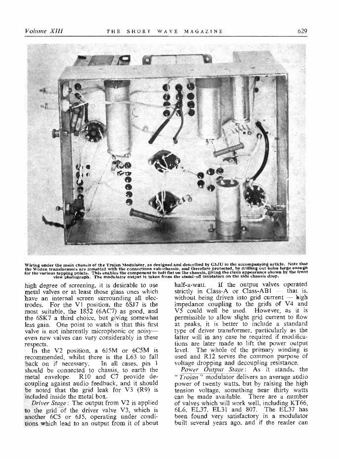
Volume XIII THE SHORT WAVE MAGAZINE 629
Wiring under the main chassis of the Trojan Modulator, as designed and described by G5JU in the accompanying article. Note thatthe Woden transformers are mounted with the connections sub -chassis, and therefore protected, by drilling out holes large enoughfor the various tapping points. This enables the component to bolt flat on the chassis, giving the clean appearance shown by the front
view photograph. The modulator output is taken from the stand-off insulators on the side chassis drop.
high degree of screening, it is desirable to usemetal valves or at least those glass ones whichhave an internal screen surrounding all elec-trodes. For the VI position, the 6SJ7 is themost suitable, the 1852 (6AC7) as good, andthe 6SK7 a third choice, but giving somewhatless gain. One point to watch is that this firstvalve is not inherently microphonic or noisy-even new valves can vary considerably in theserespects.
In the V2 position, a 6J5M or 6C5M isrecommended, whilst there is the L63 to fallback on if necessary. In all cases, pin 1
should be connected to chassis, to earth themetal envelope. R10 and C7 provide de -coupling against audio feedback, and it shouldbe noted that the grid leak for V3 (R9) isincluded inside the metal box.
Driver Stage: The output from V2 is appliedto the grid of the driver valve V3, which isanother 6C5 or 6J5, operating under condi-tions which lead to an output from it of about
half -a -watt. If the output valves operatedstrictly in Class -A or Class-AB1 - that is,without being driven into grid current - highimpedance coupling to the grids of V4 andV5 could well be used. However, as it ispermissible to allow slight grid current to flowat peaks, it is better to include a standardtype of driver transformer, particularly as thelatter will in any case be required if modifica-tions are later made to lift the power outputlevel. The whole of the primary winding isused and R12 serves the common purpose ofvoltage dropping and decoupling resistance.
Power Output Stage: As it stands, the"Trojan" modulator delivers an average audiopower of twenty watts, but by raising the hightension voltage, something near thirty wattscan be made available. There are a numberof valves which will work well, including KT66,6L6, EL37, EL31 and 807. The EL37 hasbeen found very satisfactory in a modulatorbuilt several years ago, and if the reader can

630 THE SHORT WAVE MAGAZINE February, 1956
lay his hands on a pair, it would be well touse them, retaining the resistor values specified.But there is no doubt that the valve mostreadily obtainable at a reasonable price is the807, and this type is entirely suitable. It alsohas the advantage that, if desired, the anodevoltage can be raised considerably above thatof the prototype version illustrated.
Much could be written on the various modesof operation possible, but actual results arewhat matter here. Irrespective of the mode,it is a fact that, presuming adequate drivingpower is available, the power output willdepend largely on the HT voltage applied tothe anodes of the output valves, with of coursethe screen voltage adjusted in proportion.
In the prototype modulator illustrated, theHT voltage is 325 ; with a screen dropperresistor of 8200 ohms the screen voltage isaround 270 ; the cathode bias resistor is 250ohms, giving a standing bias of 20 volts orslightly more ; and the measured power outputat low distortion is approximately 20 watts,with a maximum approaching 27 watts. Allow-ing for a 10% loss in the modulation trans-former, the audio energy is sufficient for full,modulation of a 36-40 watt (DC input) carrier.In practice, this means there is ample in reservefor modulation of the conventional 25 -watttransmitter used by a newly -licensed amateur,and distortion should be non-existent.
It will be noted that self -bias is employed,so cutting out the need for a separate sourceof bias. With cathode bias, the valves mustnot be driven hard or distortion will result.If rather more power is required-say up to25 watts-the anode voltage should be raisedto 350 or 360 volts, which simply means usinga slightly larger mains transformer with a
secondary winding giving 350-0-350 volts.Changes in some resistor values are then neces-sary, as detailed later.
The output is now reaching nearly the limitof the modulation transformer rating, but ifthat little extra is required to bring the outputup to the full 30 watts, it can readily beachieved by changing over from self -bias tofixed bias. The anode voltage is thereby raisedby the amount previously dropped across thecathode resistor (now omitted), whilst the out-put valves can be driven a little harder.
Alternatively, if the modulator is requiredfor Top Band work only, a smaller mains trans-former can be fitted, giving, say, 250 voltsHT, with appropriate changes in resistorvalues.
In all cases the standing anode current ofV4 and V5 together should be between 80
and 90 milliamperes, the total static consump-tion being approximately 100 mA. This willrise considerably when the modulator is deliver-ing power and the mains transformer should berated to give at least 150 mA.
As described and as confirmed by tests, theoutput impedance is around the 5000 ohmsmark. If the HT voltage is raised to 360,whilst retaining cathode bias, the impedancewill rise to about 8000 ohms. When usingfixed bias, the figure on which to work is 6600ohms.
From the foregoing, the reader will beginto appreciate why the design has been labelledflexible and can come to a decision whetherto build the modulator exactly as described orwhether to make minor modifications.
Power UnitThe previous paragraphs have to some
extent covered power supply requirements andthere is little more to say. The suggestionsmade by the writer in an article in the August,1955, issue of SHORT WAVE MAGAZINE are in-corporated, and in fact, the circuit of the powerunit is almost the same as Fig. 3 on page 297of that issue, the only difference being thatHT and LT are combined in one transformer.The smoothing choke shown in the upper -viewphotograph was used because it matches themains transformer, but its current rating of100 mA is unnecessarily high and a 50 mArating is quite suitable.
The rectifier valve should have a reserve ofemission to take care of peaks so that, whilstthe popular 5Z4G will do for 250 -volt opera-tion, it is better on all counts to use a largervalve. A 5R4Y is specified, but the 5Z4 and5Z3 are equally suitable.
Such refinements as a separate fuse and anindicating lamp have been omitted, but ofcourse can easily be added if wanted.
ConstructionThe photographs and drawings provide much
of the detail necessary to begin construction.The layout drawing is intended to be treatedas a guide only since individual componentswill probably not fit exactly as shown. How-ever, the general idea should be followed fairlyclosely, to keep the various stages in propersequence, and well separated from each other.
It is convenient to commence with the speechamplifier box. The only holes necessary arethe large ones for the valveholders, and two of4 in. dia'r.eter for the microphone jack and theaudio gain potentiometer. In the base are threesmall holes-one for HT, one for the LT leads
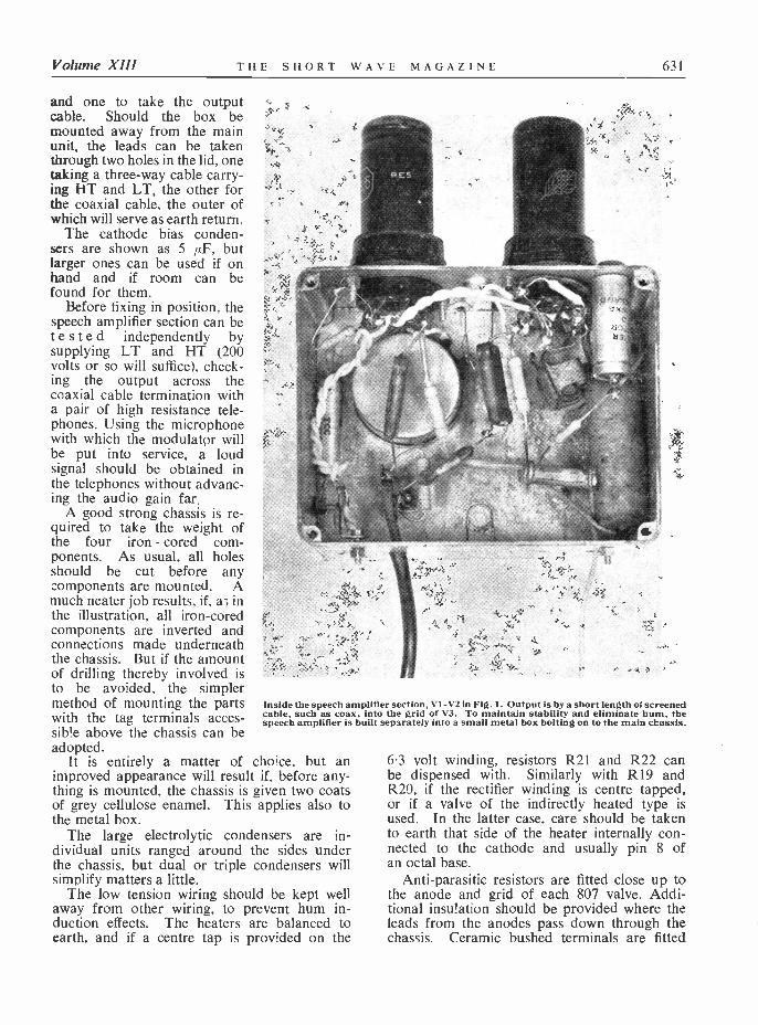
Volume XIII THE SHORT WAVE MAGAZINE 631
and one to take the outputcable. Should the box bemounted away from the mainunit, the leads can be takenthrough two holes in the lid, onetaking a three-way cable carry-ing HT and LT, the other forthe coaxial cable, the outer ofwhich will serve as earth return.
The cathode bias conden-sers are shown as 5µF, butlarger ones can be used if onhand and if room can befound for them.
Before fixing in position, thespeech amplifier section can betested independently bysupplying LT and HT (200volts or so will suffice), check-ing the output across thecoaxial cable termination witha pair of high resistance tele-phones. Using the microphonewith which the modulator willbe put into service, a loudsignal should be obtained inthe telephones without advanc-ing the audio gain far.
A good strong chassis is re-quired to take the weight ofthe four iron - cored com-ponents. As usual, all holesshould be cut before anycomponents are mounted. Amuch neater job results, if, as inthe illustration, all iron -coredcomponents are inverted andconnections made underneaththe chassis. But if the amountof drilling thereby involved isto be avoided, the simplermethod of mounting the partswith the tag terminals acces-sib!e above the chassis can beadopted.
It is entirely a matter of choice, but animproved appearance will result if, before any-thing is mounted, the chassis is given two coatsof grey cellulose enamel. This applies also tothe metal box.
The large electrolytic condensers are in-dividual units ranged around the sides underthe chassis, but dual or triple condensers willsimplify matters a little.
The low tension wiring should be kept wellaway from other wiring, to prevent hum in-duction effects. The heaters are balanced toearth, and if a centre tap is provided on the
Inside the speech amplifier section, VI -V 2 in Fig. 1. Output is by a short length of screenedcable, such as coax, into the grid oI V3. To maintain stability and eliminate hum, thespeech amplifier is built separately into a small metal box bolting on to the main chassis.
6.3 volt winding, resistors R21 and R22 canbe dispensed with. Similarly with R19 andR20, if the rectifier winding is centre tapped,or if a valve of the indirectly heated type isused. In the latter case, care should be takento earth that side of the heater internally con-nected to the cathode and usually pin 8 ofan octal base.
Anti -parasitic resistors are fitted close up tothe anode and grid of each 807 valve. Addi-tional insulation should be provided where theleads from the anodes pass down through thechassis. Ceramic bushed terminals are fitted
Con
nect
ions
for
WO
DE
N T
ypes
UM
.1, U
M.2
, UM
.3 a
nd U
M.4
Mod
ulat
ion
Tra
nsfo
rmer
s
PRIM
AR
Y C
ON
NE
CT
ION
SFO
R M
OD
UL
AT
OR
VA
LV
ES
Join
9& 1
0co
nn. t
o
SEC
ON
DA
RY
CO
NN
EC
TIO
NS
AN
D I
MPE
DA
NC
ES
FOR
RF
LO
AD
Join
7& 1
18
&12
¡
Join
1& 5
2 &
6
Join
9& 1
0co
on. t
o
I
Join
IJo
in9&
10
8& 9
conn
. to
conn
. to
Join
7& 9
10 &
12
Join
8& 9
10 &
11
Join
3& 4
conn
. to
Join
3& 4
coon
. to
Join
2& 3
com
.to
.loin
Join
3& 4
I& 3
conn
. to
4 &
6A
-to
-A
Aud
io V
alve
s7
& 1
28
& 1
28
& 1
17
& 1
2co
m. t
oco
m.
toI
& 6
2 &
61
&6
2 &
5co
nn. t
oco
ny. t
oco
nn. t
oIm
peda
nce
AC
TA
7& 1
08&
10
I&4
7& 8
1& 2
Ohm
s.20
002
3 -4
586
0063
5043
0036
2021
5010
70-
-20
020
00I
2-5
615
700
1140
079
0066
5039
2019
50-
--
--
350
3000
23-
-45
1300
094
0065
0055
0032
4016
20-
--
300
3000
12-
56
2350
017
000
1180
010
000
5900
2950
--
--
-52
038
002
3-4
516
400
1200
082
0070
0041
0020
50-
--
-38
038
00I
2-5
629
800
2150
015
000
1260
075
0037
40-
--
--
660
4000
23-
-45
1740
012
500
8650
7300
4300
2160
--
--
-40
040
008
9-10
11-
--
5500
3450
2850
1850
1380
-25
0
5000
23-
--4
521
600
1570
010
800
9150
5400
2700
--
-50
0-
5000
89-
1011
--
--
--
7000
4300
3500
2300
1730
-A
0060
001
3-4
686
0063
5043
0036
2021
4010
70--
--
--
200
--
6000
89-
10II
--
--
--
8300
5150
4250
2750
2180
-37
066
00I
3-4
695
0070
0047
5040
0023
5011
80-
--
--
220
--
6600
89-
1011
--
--
--
9100
5650
4660
3000
2400
-40
570
00I
3-4
610
000
7300
5050
4280
2500
1250
--
--
-23
0-
7000
89-
1011
--
--
--
9700
6000
5000
3200
2400
-43
080
001
3-4
612
000
8400
5800
4900
2900
1440
--
--
-27
0--
8000
89-
1011
--
--
--
1100
069
0056
5037
0027
60-
500
9000
13-
46
1300
094
0065
0055
0032
0016
20-
300
9000
8.9-
1011
--
--
--
1250
077
5063
0041
5031
00-
550
9000
79-
1012
--
--
--
6200
3900
3200
2050
1551
1-
275
1000
0I
3-4
614
400
1050
072
0061
0036
0018
00-
--
---
330
1000
08
9-10
11-
--
--
1400
086
0071
0046
0034
50--
600
1000
07
9-10
12-
--
--
-69
0043
0035
0023
0017
40-
310
1200
0I
3- 4
617
400
1250
087
0072
5043
2021
10-
-40
012
000
79-
1012
--
--
--
8300
5150
4250
2750
2070
-37
014
000
79-
1012
---
--
-97
0060
0049
0032
0024
40--
430
1600
07
9-10
12-
--
-11
000
6900
5600
3700
2789
500
1800
07
9-10
12-
--
--
1250
077
5063
0041
5031
40-
550
Col
s.1
23
"4
56
78
910
lI12
1314
15
TY
PE U
M. 1
....
TY
PE U
M. 2
....
TY
PE U
M. 3
....
TY
PE U
M. 4
....
Max
. Aud
io P
ower
30 w
atts
.60
wat
ts.
120
wat
ts.
250
wat
ts.
DC
Inp
ut, R
F PA
60 w
atts
.I2
0 w
atts
.24
0 w
atts
.50
0 w
atts
.
Max
. DC
Cur
rent
120
mA
200
mA
250
mA
400
mA
Cou
rtes
y W
oden
Tra
nsfo
rmer
Co.
, Ltd
., M
oxle
y R
oad.
Bils
ton,
Sta
ffs.
o ..1
Volume XIII THE SHORT WAVE MAGAZINE 633
at the rear of the chassis and are connectedto the appropriate output tags on the modula-tion transformer.
TestingAfter buttoning the speech amplifier to the
main unit, tests can be made prior to tryingout the modulator on the air. The primaryand secondary connections to the Woden UM 1modulation transformer will depend on theworking impedances (volts/current ratio) of theassociated equipments. For example, if thetransmitter rating is 400v., 80 mA (equal to animpedance of 5000 ohms): The anodes of V4and V5 go to taps 2 and 5, whilst 3 and 4 areconnected together and taken to maximumHT. Output is taken from taps 7 and 10, with7 and 9 connected together and also 10 and 12.
But a transmitter running at 500 volts, 50mA would have an impedance twice as great,viz., 10,000 ohms, and then the appropriatesecondary connections would be to tags 8 and11, with 9 and 10 connected together.
Both when being tested and when put intoactual operation, the modulator should beearthed with a short length of heavy cable.
When making tests, it is essential to placesome form of load across the modulator outputterminals. A mains lamp is not really suitablebecause the low cold resistance will heavilydamp the valves, although a 25 -watt lamp willglow fairly brightly if a steady signal from atone source is applied to the input. It isbetter to use resistors approximating in valueto the normal load impedance. With two re-sistors in- series-say, a 1000 ohm and a 4000ohm to make up a total of 5000 ohms-a roughcheck of power output can be made by con-necting an AC voltmeter across the resistor oflower value. In the example quoted, one -fifthof the full power will be developed across the1000 -ohm resistor and a voltage rising to 60or so at peaks should be indicated on themeter, when the audio gain control has beenadjusted to give the right amount of gain.This latter will depend largely on the sensi-tivity of the microphone (different makes varyin this respect), but there is plenty in handand only with a very insensitive microphonewill it be necessary to advance the controlbeyond the halfway position. If tests are madewith a sine wave input, checks should be inter-mittent or the output valves will overheat.
A Final WordThe inherent stability of the amplifier is
high, but it must be emphasised once againthat the grid of the first valve is extremely
susceptible to stray pick-up and, moreover,this grid is, in effect, connected out from thespeech amplifier to the microphone termina-tion. The microphone will be handled by theoperator, whose body, in itself, is a high im-pedance source of hum and noise, as well asbeing a collector of stray RF energy ! Forverification of this statement, one has onlyto witness the odd waveforms produced on anoscilloscope trace when a finger is placed onthe input terminal or lead.
Any likelihood of pick-up from this or othersources must be reduced to an absolute mini-mum. For instance, the usual type of Bake-lite shrouded plug terminating the microphonecable leaves a mass of metal unscreened elec-trically. Metal tape wrapped around the plugand earthed to the cable screen is likely toeffect a definite improvement. Another sug-gestion is to forego the convenience of thetelephone plug and jack and use in place acoaxial plug and socket, so making certainof very complete screening. There are alsofully screened microphone plug -socket assem-blies available for this purpose.
Then there is the microphone itself. If thecrystal element is inside a metal case, itselfearthed, there will be no difficulty. But somemicrophones have moulded plastic cases andthe construction may be such as to leave some" hot " metal-terminals, clips and a length ofwire - exposed to stray pick-up. Someingenuity will then be required to add metallicscreening in one form or another, withoutspoiling the appearance of the microphone. Itwill be appreciated that these measures, as wellas preventing undesirable audio frequenciesreaching the grid of the first valve, will alsohave the effect of greatly reducing the possi-bility of stray RF reaching the modulator, withthe overall result of extremely good stabilityirrespective of the transmitter frequency.
RI'_
RI5
Rlii
250 volts HT
2.000 ohms
150 ohms
1,000 ohms
350 volts HT
7.500 ohms
300 ohms
10,000 ohms
There will be no need to change any of theresistor values in the speech amplifier sectionwith change of HT line voltage. The gain willrise with an increase of HT voltage, but thisis a desirable feature. Details of necessaryalterations in the values of resistors formingpart of the main unit are given above.
(See over for notes on Table p.632.)
634 THE SHORT WAVE MAGAZINE February, 1956
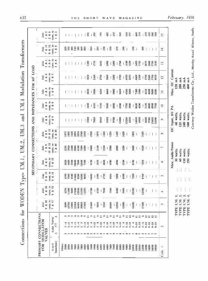
EDITORIAL NOTE: The most versatile,widely used and readily available modulationtransformer is the Woden, made in four powerratings. The Table facing p.633 gives detailedinformation on the connection sequence-whichis the same for all four types-and also thepower and current ratings for each size. Allfour types have a total of 12 tapping points,numbered in the same order for each size.
Interpretation of the Table of Connectionsis simple. Suppose the modulator consists of apair of 6L6's in Class-AB2 which (from thedata on the application of 6L6's) are shownto have an anode -to -anode load impedance of6000 ohms ; this value is found in the left-hand column (1) of the Table on p.632, withthe appropriate connection sequence in thenext column. The PA to be modulated mightbe an 807 running 50 watts DC input at 500volts. From Ohm's Law, this gives a PA anodeimpedance of 5000 ohms ; looking along theTable, opposite the lower of the two 6000 -ohmlines in Col. 1, 5150 ohms is found in Col. 10 ;
this is near enough for a good match, and theconnection sequence is read off in the headingto Col. 10. It means that the points num-bered " 3 " and " 4 " on the transformer arewired together, and that points " 2 " and " 6 "are connected in series with the HT supplyto the PA.
On the primary side, the anodes of the6L6's are taken to " 8 " and " 11 " respectively,and the HT feed (for the modulator) to thejunction of " 9 " and " 10."
In view of the power ratings involved inthis example-about 30 watts of audio and50 watts DC input to the PA-the correctchoice of transformer would be the UM.1. Butit will be noted that the rating of the UM.2represents power levels to which most amateursaspire, and when buying a modulation trans-former, it is always a good plan to considerwhether the extra expense of the larger trans-former might not in the long run be aneconomy, since it works equally well at anypower level up to its full rating.
The N.Z. ZC i Mk. IIfor
Portable OperationCIRCUIT DETAILS AND
MODIFICATIONSC. R. PLANT (G5CP)
Many of the mobile signals to be heard on theTop Band and 80 metres emanate from a" surplus" N.Z. ZCI Mk. II transmitter!receiver assembly, which lends itself admirablyto the purpose. However, like all " surplus"
DURING the past two years a large num-ber of New Zealand ZC1 Mark I and II
Transmitter -Receivers have been sold on thesurplus market. These excellent units havefound favour with a number of mobileamateurs and are also installed at many fixedstations.
The ZC1 was designed for the use of theNew Zealand Forces as a mobile or fixed unit :it is fully tropicalised, thus making it verysuitable for outdoor use.
It is entirely self-contained in a strong metalhousing and consists of a,five-valve transmitterand a sensitive six -valve receiver, together with
equipments operated on our bands, alterationsand modifications are called for if the bestresults are to be obtained. This article dis-cusses the popular Mk. II version of the ZC1,which as it stands covers the HF end of theTop Band, as well as the 80- and 40 -metrebands in their entirety. Our contributor iswell known as a very successful IM operatorand his ideas and suggestions will be ofpractical value to all who are interested in
mobile working. Editor.
a synchronous vibrator pack which suppliesthe necessary smoothed HT.
The set in its original form can transmit andreceive phone, CW or ICW with an RF outputof between 1 and 11 watts. The power supplyfor the ZC1 is obtained from a 12 volt accumu-lator, the current consumption for an unmodi-fied Mark II unit being : -
Receiver only ... ... ... ... 2.8 A.Receiver and Transmitter Filaments 3.8 A.Transmitting CW 4.4 A.Transmitting Phone (or ICW) ... 4.9 A.
Using a 12 foot whip mounted on a car,reliable communication up to 12 miles can beexpected ; when operating on the 1.8-2.0 meamateur band this range has on many occasionsbeen considerably increased.
There are many modifications which may becarried out to improve the performance of theset. The writer, however, proposes to limitthe scope of this article to those which he has
Volume XIII THE SHORT WAVE MAGAZINE 635
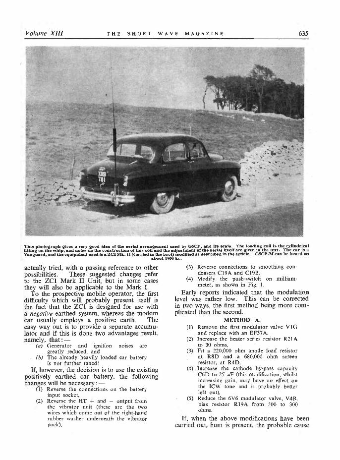
This photograph gives a very good idea of the aerial arrangement used by G5CP, and its scale. The loading coil is the cylindricalfitting on the whip, and notes on the construction of this coil and the adjustment of the aerial itself are given in the text. The car is aVanguard, and the equipment used is a ZCI Mk. II (carried in the boot) modified as described in the article. G5CP/M can be heard on
about 1900 kc.
actually tried, with a passing reference to otherpossibilities. These suggested changes referto the ZC1 Mark II Unit, but in some casesthey will also be applicable to the Mark I.
To the prospective mobile operator, the firstdifficulty which will probably present itself isthe fact that the ZC1 is designed for use witha negative earthed system, whereas the moderncar usually employs a positive earth. Theeasy way out is to provide a separate accumu-lator and if this is done two advantages result.namely, that : -
(a) Generator and ignition noises aregreatly reduced, and
(b) The already heavily loaded car batteryis not further taxed!
If, however, the decision is to use the existingpositively earthed car battery, the followingchanges will be necessary : -
(1) Reverse the connections on the batteryinput socket,
(2) Reverse the HT + and - output fromthe vibrator unit (these are the twowires which come out of the right-handrubber washer underneath the vibratorpack),
(3) Reverse connections to smoothing con-densers C19A and C19B.
(4) Modify the push -switch on milliam-meter, as shown in Fig. 1.
Early reports indicated that the modulationlevel was rather low. This can be correctedin two ways, the first method being more com-plicated than the second.
METHOD A.(1) Remove the first modulator valve V1G
and replace with an EF37A.(2) Increase the heater series resistor R21A
to 30 ohms.(3) Fit a 220,000 ohm anode load resistor
at R8D and a 680,000 ohm screenresistor, at R4D,
(4) Increase the cathode by-pass capacityC6D to 25 µF (this modification, whilstincreasing gain, may have an effect onthe ICW tone and is probably betterleft out),Reduce the 6V6 modulator valve, V4B,bias resistor RI9A from 500 to 300ohms.
If, when the above modifications have beencarried out, hum is present, the probable cause
(5)
636 THE SHORT WAVE MAGAZINE February, 1956
--x_k1.1__0' O-3413`}T f 1X91] f_ _ ___1
%, M91
Q10;+`a-¡ .1
1
113'
o
rV
11
941]1913
--i 491J
00N-.060
1119,
99D
119]11
- y91,391_1_411
O9t30
169
%0000p-11--!
8IL
Ñ<
393T 03.00 4,:o 3113
o !1
o OS D
1019
I91D 393tineº13
i :"_r -+0
1S3º/r95
1 TMIL]
.P Wit
49,091r-'s
tio"3 9/119So- Q4
311 r,cI 3SI3 e o
iyehiI i79
` N9I] F
rnF
~Inn
valorvvvv---,,12
I_w9nvr
393 1913 / 1vNI/\'con.
v011
.12
á
3º3
8913
a-^ - 11
--ee á Ot133L1rS13
S/VLS ó
3ZZ31MA
NMN 34a
--"""3
991]
=1aZ3 1/198 y,ML3
- \ Q001Q..Gr9\ f/'1"4iJ 7
vyL39Z3 1
s/rZ.L.'--- 4000090r-rSn
OS13rZZ3
Z L/r9S
Noij O
S/ra5x
Q1:314 -
9.Q9 0 0J'Vt11
3L3y
/h9t"'e---.0 IDA Q.9`VL1l
VSS 15
rol 0. 9ol
09131
391]
SI3 <YY
893
}
1I--waB91]
l V
L/rIS
Vivos 000 rV 5-1
Y.i 883 f/r15 6ÓÓ
_. ,.. _I ; j v[3VSl 1
/r1]
I/r15 . VL1-'` 40006a0`ir,s Vll rt,1. --
NIL rt,
rs
VS) ,b
U-- : r9,
.11
o
4
Volume XIII THE SHORT WAVE MAGAZINE 637
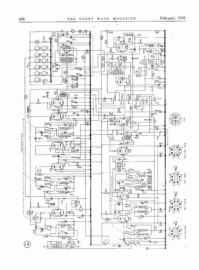
Fig. 2. Circuit complete of the N.Z. ZC1 Mk. II equipment,as in the original, is shown on the opposite page, with thecircuit values in full in the table. The transmitter RF sectionis V1F, VIE, V4A, consisting essentially of a VFO-Buffer-PAarrangement, with V4B as modulator and V1G as the singlespeech amplifier (for a carbon microphone). The receiversection is VIA, V2A, V1B, V3A, VIC, with V1D as BFO. Poweris by synchronous vibrator rectifier, and maximum currentdrain, at 12 volts, is 5 amps. on phone. Change -over controlis by a relay system, with switching for CW/phone workingand band selection. In the ordinary way, the band switch(shown as for the LF range) would remain as set for 160 -
metre working.
will be found to be on the microphone side.An examination of the circuit shows that itmay be introduced by the relay switch wire,which shares a common earth return with themicrophone circuit. The easiest way to correctthis is to run a separate wire for the relaycontrol circuit.
METHOD B.A much quicker method is to substitute a
6K7G for the 6U7G as fitted at V1G withoutany circuit changes, and to replace the movingcoil microphone by a P.O. type carbon inset.In order to energise the microphone it is onlynecessary to cut the blue lead which runs tothe terminal at the top of the handset interiorand to pass the two ends through suitable holesdrilled in the back of the case to a 11 -voltcell clipped to the case. The energising currentwill then be switched on and off by the normalsend/receive switch already mounted on thehandset.
In some instances modulator instability isevident if the microphone energising batteryis incorrectly polarised, but it is a simple matterto correct this.Aerial Arrangement
Attention can next be turned to the aerial.It is possible to radiate a reasonable signal byemploying an 8 or 12 foot whip fixed to anyconvenient part of the car, provided it is wellinsulated from the metal work. Infinitelyimproved results can be obtained if the aerialis tuned to a quarter -wave length by means ofa loading coil. In the writer's case this is
ToMeter neg.
TOBattery neg.
o
ToSwitch S2A/3
ToMeter pos.
E
Table of ValuesFig. 2. Circuit of the ZC1 Mk. 11 unmodified.
CIA = 15 µµF silveredmica
CI9A-B = 25 µF, electrolytic,25v. wkg.
C2A-C = Gang condenserC2D-F = Gang condenser
C20A 5 µµF, silveredmica, 400v. wkg.
C3A = 5/35 µµF, variableC4A = .02 µF, paper, 400v.
wkg.
C21A-B .001 µF, ' PostageStamp' mica, 4Wv. wkg.
C5A-B = .02 µF, paper, 400v.wkg.
C6A-H = 0.1 µF, paper, 400v.wkg.
C7A-J = 3-30 µµF, Philips'Trimmer
C22A-C
C23A-B
.00025 µF, ' Post-age Stamp ' mica,400v. wkg.
.011 µF, mica, 1800v. wkg.
C8A-I = .0001 µF, ' Postage RIA = 20,000 ohms, 2-w.Stamp ' mica, 400 R2A-G = 50,000 ohms, }-w.v. wkg. R3A = 25,000 ohms, 2-w.
C9A-B = 500-1,200 µµF,semi -fated
R4A-DR5A
==
0.5 megohms, }-w.10 megohms, }-w.
CIOA = .0005 µF, ' Postage R6A-C = 0.25 megohms, }-w.Stamp' mica, 400 R7A-E = 1 megohm, }-w.v. wkg. R8A-D = 100,000 ohms, }-w.
C11B-C = .0005 µF, ' PostageStamp ' mica, 400
R9A-B = 0.5 megohm, poten-tiometer
v. wkg. RIOA-B = 2,000 ohms, }-w.C12A = .0015 µF, ' Postage RI IA -B = 200 ohms, }-w.
Stamp ' mica, 400 R 12A = 1,000 ohms, }-w.v. wkg. RI3A = 1,400 ohms, 2-w.
CI3A-D = .00008 µF, mica,400v. wkg.
Rl4AR15A
==
55 ohms, }-w.50 ohms, 4-w.
C14A-C = 0.25 µF, paper,400v. wkg.
RI 6AR17A
==
15,000 ohms, 1-w.20,000 ohms, }-w.
CI5A-E _ .00005 µF, ' Post- R18A = 10,000 ohms, }-w.age Stamp' mica, R19A = 500 ohms, 2-w.400v. wkg. R20A = 200 ohms, l -w.
CI6A-M = .004 µF, ' Postage R2IA = 20 ohms, 2-w.Stamp' mica, 400 R22A = 100 ohms, 1-w.v. wkg. VI A -G = 6U7G
C17A = .02 µF, Paper, 400 V2A = 6K8Gv. wkg. V3A = 6Q7GT
CI8A-F = 10 µF, double elec- V4A-B 6V6GTtrolytic, 450v.wkg.
VIB = 12v. synchronous,7 -pin
Fig. 1. If the equipment is to be run from the existing carbattery - which in the case of most modern cars will beconnected with the positive side earthed - the meter switchconnections should be altered as shown here. However, tokeep the load on the car's own battery within its rating, it Isbetter to use a separate 12 -volt accumulator. It would notthen be necessary to modify the meter switch, as the battery
can be connected with a negative earth.
mounted four feet above the base and consistsof 240 turns 18g. enamelled copper wire closewound on a 11 in. Tufnol former. Tappingsare brought out at 5, 10, 15 and 20 turns atthe top, and single turns 1-6 at the bottom.This allows selection over a wide range offrequencies and has proved to be adequate forthe Top Band frequencies covered by the MarkII set.
An easy way in which to obtain resonanceon 3.5 me is to bring out a tap at the coilcentre, but a more efficient result will be ob-tained if a special coil is used for each band.When using aerial taps it is important to leaveall unused turns open-ended otherwise the coilwill not tune satisfactorily.
Many experiments have been carried outusing a variety of loading coils, and it has beenascertained that when the aerial carries a load-ing coil at some point above the base (thehigher the better) improved efficiency results.In the writer's case, 4 ft. was considered anideal height in view of the difficulties experi-enced due to mechanical instability when theheavy coil was elevated still further.
Initial tests were made with the aerialsystem resonating at half -wave, but it wasfound that a quarter -wave aerial gave a muchimproved result. [OYe1
638 THE SHORT WAVE MAGAZINE February, 1956
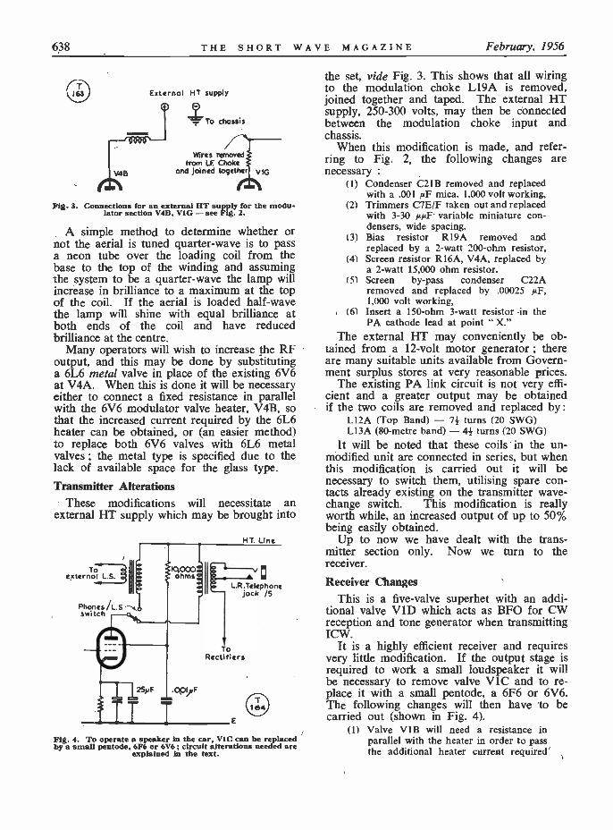
Externo) HTTsupply
`- To chassis
Wires removedfrom LF. Choke
and joined together VfG
Fig. 3. Connections for an external HT supply for the modu-lator section V4B, V1G - see Fig. 2.
A simple method to determine whether ornot the aerial is tuned quarter -wave is to passa neon tube over the loading coil from thebase to the top of the winding and assumingthe system to be a quarter -wave the lamp willincrease in brilliance to a maximum at the topof the coil. If the aerial is loaded half -wavethe lamp will shine with equal brilliance atboth ends of the coil and have reducedbrilliance at the centre.
Many operators will wish to increase the RFoutput, and this may be done by substitutinga 6L6 metal valve in place of the existing 6V6at V4A. When this is done it will be necessaryeither to connect a fixed resistance in parallelwith the 6V6 modulator valve heater, V4B, sothat the increased current required by the 6L6heater can be obtained, or (an easier method)to replace both 6V6 valves with 6L6 metalvalves ; the metal type is specified due to thelack of available space for the glass type.Transmitter Alterations
These modifications will necessitate anexternal HT supply which may be brought into
Toexternal L.S.
Phones/L.5-1,switch
.001F
HT. Line
L.R.Telephonejock /5
ToRectifiers
Fig. 4. To operate a speaker in the car, VIC can be replacedby a small pentode, 6F6 or 6V6 ; circuit alterations needed are
explained in the text.
the set, vide Fig. 3. This shows that all wiringto the modulation choke L19A is removed,joined together and taped. The external HTsupply, 250-300 volts, may then be connectedbetween the modulation choke input andchassis.
When this modification is made, and refer-ring to Fig. 2, the following changes arenecessary :
(I) Condenser C21B removed and replacedwith a .001 µF mica. 1.000 volt working,
(2) Trimmers C7E/F taken out and replacedwith 3-30 µµF variable miniature con-densers, wide spacing.
(3) Bias resistor R19A removed andreplaced by a 2 -watt 200 -ohm resistor,
(4) Screen resistor R16A, V4A, replaced bya 2 -watt 15,000 ohm resistor.
(5) Screen by-pass condenser C22Aremoved and replaced by .00025 µF,1,000 volt working,
(6) Insert a 150 -ohm 3 -watt resistor in thePA cathode lead at point " X."
The external HT may conveniently be ob-tained from a 12 -volt motor generator ; thereare many suitable units available from Govern-ment surplus stores at very reasonable prices.
The existing PA link circuit is not very effi-cient and a greater output may be obtainedif the two coils are removed and replaced by :
L12A (Top Band) - 71 turns (20 SWG)L13A (80 -metre band) - 41 turns (20 SWG)
It will be noted that these coils in the un-modified unit are connected in series, but whenthis modification is carried out it will benecessary to switch them, utilising spare con-tacts already existing on the transmitter wave -change switch. This modification is reallyworth while, an increased output of up to 50%being easily obtained.
Up to now we have dealt with the trans-mitter section only. Now we turn to thereceiver.
Receiver ChangesThis is a five -valve superhet with an addi-
tional valve V 11) which acts as BFO for CWreception and tone generator when transmittingICW.
It is a highly efficient receiver and requiresvery little modification. If the output stage isrequired to work a small loudspeaker it willbe necessary to remove valve VIC and to re-place it with a small pentode, a 6F6 or 6V6.The following changes will then have to becarried out (shown in Fig. 4).
(1) Valve V1B will need a resistance inparallel with the heater in order to passthe additional heater current required
Volume XIII THE SHORT WAVE MAGAZINE 639
by the new valve,(2) R10A should be removed and a
650 -ohm, 1 -watt resistance substituted,(3) C18A requires a 25µF electrolytic con-
denser in parallel,(4) A screen connection via a 10,000 -ohm,
1 -watt resistance should be taken fromthe HT side of T1A, and a .001 /IF400v. working fixed condenser con-nected between the screen and earth,
(5) A miniature pentode output transformerwill be required to load the externalspeaker ; this can be wired in circuittogether with a selector switch, so thatthe headphones or, alternatively, theloud speaker, may be switched intocircuit.
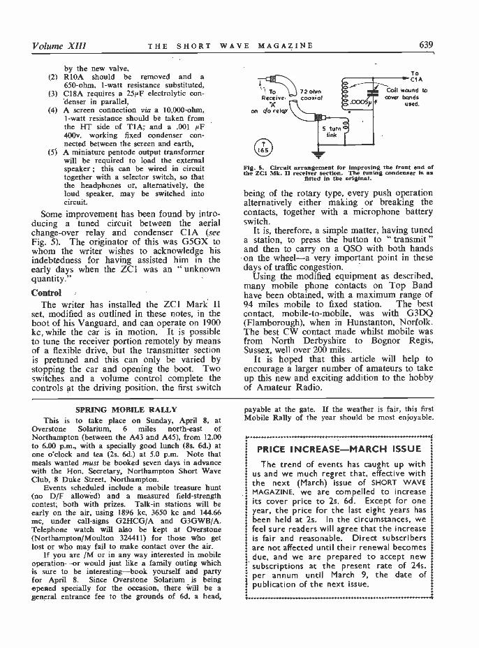
Some improvement has been found by intro-ducing a tuned circuit between the aerialchange -over relay and condenser OA (seeFig. 5). The originator of this was G5GX towhom the writer wishes to acknowledge hisindebtedness for having assisted him in theearly days when the ZC1 was an " unknownquantity."
ControlThe writer has installed the ZC1 Mark 11
set, modified as outlined in these notes, in theboot of his Vanguard, and can operate on 1900kc while the car is in motion. It is possibleto tune the receiver portion remotely by meansof a flexible drive, but the transmitter sectionis pretuned and this can only be varied bystopping the car and opening the boot. Twoswitches and a volume control complete thecontrols at the driving position, the first switch
To 72ohmReceive: coaxial
on do relay
ToCl A
Coil wound tocover bands
used.
Fig. 5. Circuit arrangement for improving the front end ofthe ZCI Mk. II receiver section. The tuning condenser is as
fitted in the original.
being of the rotary type, every push operationalternatively either making or breaking thecontacts, together with a microphone batteryswitch.
It is, therefore, a simple matter, having tuneda station, to press the button to " transmit "and then to carry on a QSO with both handson the wheel-a very important point in thesedays of traffic congestion.
Using the modified equipment as described,many mobile phone contacts on Top Bandhave been obtained, with a maximum range of94 miles mobile to fixed station. The bestcontact, mobile -to -mobile, was with G3DQ(Flamborough), when in Hunstanton, Norfolk.The best CW contact made whilst mobile wasfrom North Derbyshire to Bognor Regis,Sussex, well over 200 miles.
It is hoped that this article will help toencourage a larger number of amateurs to takeup this new and exciting addition to the hobbyof Amateur Radio.
SPRING MOBILE RALLYThis is to take place on Sunday, April 8. at
Overstone Solarium, 6 miles north-east ofNorthampton (between the A43 and A45), from 12.00to 6.00 p.m., with a specially good lunch (8s. 6d.) atone o'clock and tea (2s. 6d.) at 5.0 p.m. Note thatmeals wanted must be booked seven days in advancewith the Hon. Secretary, Northampton Short WaveClub, 8 Duke Street, Northampton.
Events scheduled include a mobile treasure hunt(no D/F allowed) and a measured field -strengthcontest, both with prizes. Talk -in stations will beearly on the air, using 1896 kc, 3650 kc and 144.66mc, under call -signs G2HCG/A and G3GWB/A.Telephone watch will also be kept at Overstone(Northampton/Moulton 324411) for those who getlost or who may fail to make contact over the air.
If you are /M or in any way interested in mobileoperation-or would just like a family outing whichis sure to be interesting-book yourself and partyfor April 8. Since Overstone Solarium is beingopened specially for the occasion, there will be ageneral entrance fee to the grounds of 6d. a head,
payable at the gate. If the weather is fair, this firstMobile Rally of the year should be most enjoyable.
PRICE INCREASE-MARCH ISSUEThe trend of events has caught up with
us and we much regret that, effective with1 the next (March) issue of SHORT WAVE
MAGAZINE, we are compelled to increaseits cover price to 2s. 6d. Except for oneyear, the price for the last eight years hasbeen held at 2s. In the circumstances, wefeel sure readers will agree that the increaseis fair and reasonable. Direct subscribersare not affected until their renewal becomesdue, and we are prepared to accept newsubscriptions at the present rate of 24s.per annum until March 9, the date ofpublication of the next issue.
i
640 THE SHORT WAVE MAGAZINE February, 1956
L. H. THOMAS, M.B.E. (G6QB)
WE have a very mixed bag toreport this month. After the
really wonderful conditions pre-vailing in November and Decem-ber, all bands seems to have takena nasty dip, and activity has fallenoff in proportion. This, we ratherthink, is more seasonal thanionospheric (if one may put it likethat). Several times between 1946and 1953 we note from our logthat January was perhaps theworst month on the HF bands.and we feel sure that the DXseason everyone is looking forwardto will be a good one-and that itwill be well under way by theearly Spring.
DX has been quite good onoccasions, but the general level ofthe bands, at the time of writing.is nothing like it was a month ago.It is also significant that the 160 -metre Trans-Atlantics on Sundaymornings have not been up to lastyear's standard, so far, and thatthe Top Band DX is (as one wouldexpect) more difficult as the sun-spot cycle progresses. We willstart at the LF end of ourspectrum.
Top Band DXLots of G's were active on
December 4, but the only onereported on the other side byW1BB was G5JU (Birmingham),who worked WIBB, W1EPE andK2BRW. The North -South pathwas good, with KP4CC andKZ5PB getting into the States verywell.
On December 8 another " first "was chalked up. DL1FF and afew others obtained special per-mission to use the band. andDLIFF himself worked WIBB.3FBV, 3RGQ and 8GDQ.W3RGQ was the first to work DL.
COMMENTARY
W1DTG
CALLS HEARD, WORKED and QSL'dDecember 11 was better. Most
of the old -stagers among the G'sgot across, and foué stations-G3IGW, 3JEQ, 3KKP and 5NS-made it for the first time. DL1FFwas also working them again.
On December 13 XE2OKshowed up on 1822 kc and workedsome W's ; on the 17th quite afew G's made it. December 18was another good morning, theprincipal excitement being pro-vided by YN1AA on 1820 kc.Most of the usual G's were on,also DL1FF, and W1BB reportsthat some of the G's stayed inuntil 0825, at which hour G3GGNpeaked to 559 and then went out.Another `first' was made on Decem-ber 15, when W2QHH workedYNIAA on both phone and CW.
December 25-Christmas morn-ing!-and still a fair amount ofactivity, but the only Europeanworked by W1BB was G5JU, whowas heard from 0500 until 0730 at449/559. DL1FF and HB9CMwere also heard weakly over there.DLIFF, curiously, says that Wsignals are scarce in Germany andthat he hears KP4CC, KZ5PB andYNIAA much better than the W's.
Much of the above informationcomes from W1BB's excellent
bulletins, for which we thank him_British stations seem to be veryreticent about their own doingsand mostly don't trouble to notifyus when they work across thePond (even for the first time), butwe hear about it just the same!This does not mean that we don'twant reports from this end-weshould like far more of them,please.
The report from G5JU is thaton Christmas morning the bandwas noisy, but conditions were nottoo bad ; at any rate, he workedW3EIS, W3FBV, W8ANO andW9PNE, as well as W1BB. OnDecember 27, the noise -level waslow, but ship -shore QRM was verytroublesome ; G5JU w or k e dW2EQS, W3FhV, W3RGQ,W4TZN and W9NPC. He remarksthat G3FPQ was evidently "gettingover well, working W2EQS andbeing called by W4TZN. January1st, New Year's morning, wasquiet, with few DX signals up, butG5JU managed to raise W1AHX,W1BB and W2QHH. G5JU'sopinion is that conditions so farthis season have not been toogood, though activity is being wellmaintained by the DX clan.
G3IGW (Halifax) tells us that
Volume X111 THE SHORT WAVE MAGAZINE 641
on December 18 he heard YN1AA,KZ5PB, sundry W's and SP3CU.He thought the latter was a bitodd, but a later QSO with him onEighty proved him to be O.K.
G3FPQ (Bordon) spent a longtime on finding an aerial whichwould get him across on TopBand, and tried four in all, includ-ing a 900 -ft. wire! He finallysettled for a 250 -ft. centre -fed, 50feet high. With this he had W1BBback to his CQ call on January 2.Later, on January 8, he raisedWIBB, 2EQS, 4TKR, 8ANO and9PNE-pretty good proof that thenew aerial works. W4TKR gavehim a report of 579, but otherreports averaged S4. W4TKR, bythe way, uses only 25 watts him-self.
G3JEQ (Great Bookham) raisedWIBB and ZB1BJ on December11, the former for his first Trans -Atlantic DX.
Other Top -Band NewsHB9T (Zurich) successfully
claimed his WABC Certificate-nomean feat for an HB! - andwrites: " I am delighted to getthis award. It was quite a job toget confirmations from 61 counties.and I am as proud as when I gotthe WAC, 25 years ago. ThoughI am very QRL, I shall continueto work on 1.8 mc, trying to getmore counties."
G6VC (Northfieet) is not doingmuch on this band, having lost hishalf -wave at the beginning of theyear. He heard some W's butmade no contacts. (Mortalityamong these very long long -wireswas pretty high during the freakgales early in January?)
G3JHH (Hounslow) collectedGW3CBX in Pembroke for a newone, and received a long-awaitedQSL from Denbigh, so he is now81/82. He is looking forward tosummer and some DX-peditions.Other QSO's were with OK1AEH,GM3JFG (Ross), GM3HZA (Ren-frew) and GC3KAV (Guernsey).
Talking of DX-peditions, we areglad to hear from G3IGW that he,in company with G3JML andG3KKP, hopes to do another onethis coming Easter. G3IGW saysthat as all counties have now beenrepresented at some time or other,he wants to find out where thegreatest need is. Will those
interested therefore please drophim a card and say which oddcounties they would most like towork - he and the team will thensee what they can do about it.(QTH-R in latest Call Book).
G2CZU (Bath) claims hisWABC at last . he was thechap who could have collectedone years back if we hadn't startedthe thing from the date -line ofJanuary 1952! This time he wasconsiderably held up because twocontacts in Brecknock didn't pro-duce a QSL between them.
G3FAS (High Wycombe) hasreturned to his old stamping -ground after a burst of DX onTwenty, and sends along a much -improved score for the Top Bandladder. He was helped up byGM3KHJ (Inverness), GM3AUD(Ross). GD3UB, G2KK andG3KNQ (Leicester) and G3BK(Cambridge).
G3CO (London, S.E.14) saysthat although the improvement inthe HF bands has reduced activityon 160, he thinks a quick WABCis still possible. On January 4.
he loggedtwenty counties in half an hour.He adds that GM3KHJ always hasa queue, that activity from Banffis mighty scarce, and that a stationsigning DM3XYA showed up and
was chased by all and sundry,although no one appeared to havebeen successful. Was he genuine?
An interesting Top Bander whois genuine was HB1CM/HE (seep.541 December), worked byG5JU and others on January 14 ;there was a heavy pile-up on him,and to make matters even morecomplicated, he had chosen aCoast station frequency on whichto open up HB1CM/HE!
G3JZK (Cambridge) makes itclear that all his Top -Bandactivity is from GM, where hereturns each vacation. This timehe put up a 1000 -ft. temporaryaerial, but continuous thunder-storms spoilt his fun. However,on it he worked G3CHN/A(Devon) at 59 phone, the latterusing a +-wave vertical! 'JZKthen operated from Newtonmore,Inverness-shire, but with a verypoor aerial. He says ValenciaRadio on 1820 kc (T5) is a newmenace.
'G3GGS (Preston) raised G3ARSin Rutland for a new one, alsoGM3DGI in Edinburgh. Hemissed the HB's workedOK1AEH, who was 589 and aparticularly fine signal.
Eighty and FortyVery little that happens on
Station of G3GEN, Gloucester, who has gear for 20, 15 and 10 metres, and is also onSSB phone on 80 metres. His receivers are an HRO, a BC -348 with bandspread and a
BC -453, and he has a separate Top Band transmitter with a TTII in the PA.
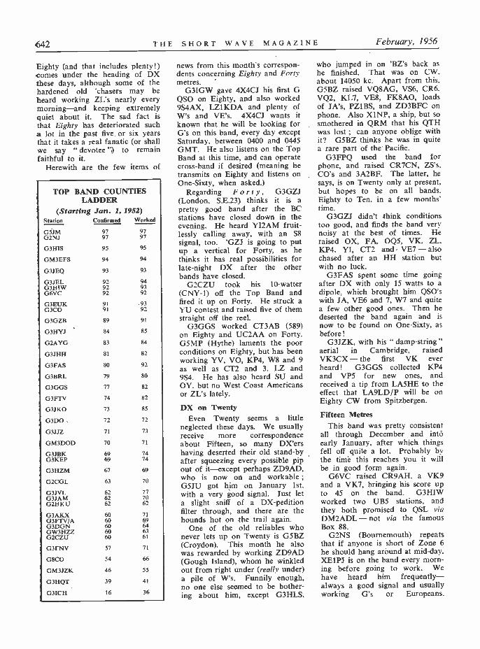
642 THE SHORT WAVE MAGAZINE February, 1956
Eighty (and that includes plenty!)comes under the heading of DXthese days, although some of thehardened old 'chasers may beheard working ZL's nearly everymorning-and keeping extremelyquiet about it. The sad fact isthat Eighty has deteriorated sucha lot in the past five. or six yearsthat it takes a real fanatic (or shallwe say " devotee ") to remainfaithful to it.
Herewith are the few items of
TOP BAND COUNTIESLADDER
(Starting Jan. 1, 1952)Station Confirmed Worked
GSJM 97 97G2NJ 97 97
G3HIS 95 95
GM3EFS 94 94
G3JEQ 93 93
G3JEL 92 94G3HIW 92 93G6VC 92 92
G3EUK 91 93G3CO 91 92
G3GZB 89 91
G3HYJ ' 84 85
G2AYG 83 84
G3JHH 81 82
G3FAS 80 92
G3BRL 79 80
O3GGS 77 82
G3FTV 74 82
G3JKO 73 85
G3D0. 72 72
G3JJZ 71 73
GM3DOD 70 71
G3JBK 69 74G3KEP 69 74
G3HZM 67 69
G2CGL 63 70
G3JVL 62 77G3JAM 62 70G2HKU 62 62
G3AKX 60 71G3FTV/A 60 69G3DGN 60 64GW3HZZ 60 63G2CZU 60 61
G3FNV 57 71
G8CO 54 66
GM3JZK 46 55
G3HQT 39 41
G3ICH 16 36
news from this month's correspon-dents concerning Eighty and Fortymetres.
G3IGW gave 4X4CJ his first GQSO on Eighty, and also worked9S4AX, LZIKDA and plenty ofW's and VE's. 4X4CJ wants itknown that he will be looking forG's on this band, every day exceptSaturday, between 0400 and 0445GMT. He also listens on the TopBand at this time, and can operatecross -band if desired (meaning hetransmits on Eighty and listens onOne -Sixty, when asked.)
Regarding Forty, G3GZJ(London, S.E.23) thinks it is apretty good band after the BCstations have closed down in theevening. He heard YI2AM fruit-lessly calling away, with an S8signal, too. 'GZJ is going to putup a vertical for Forty, as hethinks it has real possibilities forlate -night DX after the otherbands have closed.
G2CZU took his 10-watter(CNY-1) off the Top Band andfired it up on Forty. He struck aYU contest and raised five of themstraight off the reel.
G3GGS worked CT3AB (589)on Eighty and UC2AA on Forty.G5MP (Hythe) laments the poorconditions on Eighty, but has beenworking YV, VO, KP4, W8 and 9as well as CT2 and 3, LZ and9S4. He has also heard SU andOY. but no West Coast Americansor ZL's lately.
DX on TwentyEven Twenty seems a little
neglected these days. We usuallyreceive more correspondenceabout Fifteen, so many DX'ershaving deserted their old stand-byafter squeezing every possible pipout of it-except perhaps ZD9AD,who is now on and workable ;G5JU got him on January 1st,with a very good signal. Just leta slight sniff of a DX-peditionfilter through, and there are thehounds hot on the trail again.
One of the old reliables whonever lets up on Twenty is G5BZ(Croydon). This month he alsowas rewarded by working ZD9AD(Gough Island), whom he winkledout from right under (really under)a pile of W's. Funnily enough,no one else seemed to be bother-ing about him, except G3HLS,
who jumped in on 'BZ's back ashe finished. That was on CW.about 14050 kc. Apart from this.G5BZ raised VQ8AG, VS6, CR6.VQ2, KL7, VE8, FK8AO, loadsof JA's, PZ1BS, and ZD3BFC onphone. Also X1NP, a ship, but sosmothered in QRM that his QTHwas lost ; can anyone oblige withit? G5BZ thinks he was in quitea rare part of the Pacific.
G3FPQ used the band forphone, and raised CR7CN, ZS's.CO's and 3A2BF. The latter, hesays, is on Twenty only at present,but hopes to be on all bands.Eighty to Ten, in a few months'time.
G3GZJ didn't think conditionstoo good, and finds the band verynoisy at the best of times. Heraised OX, FA, 0Q5, VK, ZL.KP4, YI, CT2 and VE7 - alsochased after an HH station butwith no luck.
G3FAS spent some time goingafter DX with only 15 watts to adipole, which brought him QSO'swith JA, VE6 and 7, W7 and quitea few other good ones. Then hedeserted the band again and isnow to be found on One -Sixty, asbefore!
G3JZK, with his " damp -string "aerial in Cambridge. raisedVK3CX - the first VK everheard! G3GGS collected KP4and VP5 for new ones, andreceived a tip from LA5HE to theeffect that LA9LD/P will be onEighty CW from Spitzbergen.
Fifteen MetresThis band was pretty consistent
all through December and intoearly January, after which thingsfell off quite a lot. Probably bythe timé this reaches you it willbe in good form again.
G6VC raised CR9AH. a VK9and a VK7, bringing his score upto 45 on the band. G3HIWworked two UB5 stations, andthey both promised to QSL viaDM2ADL - not via the famousBox 88.
G2NS (Bournemouth) repeatsthat if anyone is short of Zone 6he should hang around at mid -day.XEIPJ is on the band every morn-ing before going to work. Wehave heard him frequently-always a good signal and usuallyworking G's or Europeans.
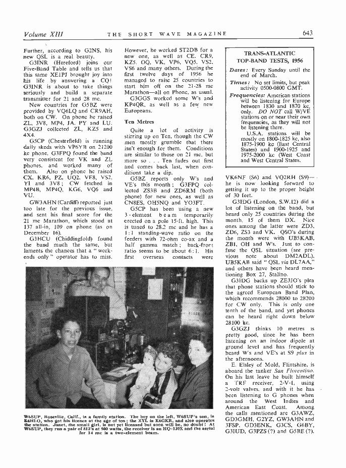
Volume XIII THE SHORT WAVE MAGAZINE 643
Further, according to G2NS, hisnew QSL is a real beauty.
G3INR (Hereford) joins ourFive -Band Table and tells us thatthis same XE1PJ brought joy intohis life by answering a CQ!G3INR is about to take thingsseriously and build a separatetransmitter for 21 and 28 mc.
New countries for G5BZ wereprovided by VQ6LQ and CR9AH,both on CW. On phone he raisedZL, 3V8, MP4, JA, PY and LU.G3GZJ collected ZL, KZ5 and4X4.
G5CP (Chesterfield) is runningdaily skeds with VP6YB on 21200kc phone. G3FPQ found the bandvery consistent for VK and ZLphones, and worked many ofthem. Also on phone he raisedCX, KR6, PZ, UQ2, VE8, VS2,YI and 3V8 ; CW fetched inMP4B, MP4Q, KG6, VQ6 andVU.
GW3AHN (Cardiff) reported justtoo late for the previous issue,and sent his final score for the21 mc Marathon, which stood at137 all -in, 109 on phone (as onDecember 16).
G3HCU (Chiddingfold) foundthe band much the same, butlaments the chances that a " week-ends only " operator has to miss.
However, he worked ST2DB for anew one, as well as CE, CR9,KZ5, OQ, VK, VP6, VQ5, VS2,VS6 and many others. During thefirst twelve days of 1956 hemanaged to raise 25 countries tostart him off on the 21-28 mcMarathon -all on Phone, as usual.
G3GGS worked some W's andKP4QR, as well as a few newEuropeans.
Ten MetresQuite a lot of activity is
stirring up on Ten, though the CWmen mostly grumble that thereisn't enough for them. Conditionsare similar to those on 21 mc, butmore so ... Ten fades out firstand comes back last, when con-ditions take a dip.
G5BZ reports only W's andVE's this month ; G3FPQ col-lected ZS3B and ZD6RM (bothphone) for new ones, as well asCN8ES, OH5NQ and YO3FT.
G5CP has been using a new3 - element beam temporarilyerected on a pole 15 -ft. high. Thisis tuned to 28.2 mc and he has a1:1 standing -wave ratio on thefeeders with 72 -ohm co -ax and ahalf gamma match ; back -frontratio seems to be about 6: 1. Hisfirst overseas contacts were
w6SUP, Roseville, Calif., is a family station. The boy on the left, W6SUP's son, isK6HLO, who got his licence at the age of ten ; the XYL is K6GKR, and also operatesthe station. Janet, the small girl, is not yet licensed but soon will be, no doubt ! AtW6SUP, they run a pair of 813's at 500 watts, the receiver is an HQ -120X and the aerial
for 14 mc is a two -element beam.
TRANS -ATLANTICTOP -BAND TESTS, 1956
Dates: Every Sunday until theend of March.
Times: No set limits, but peakactivity 0500-0800 GMT.
Frequencies: American stationswill be listening for Europebetween 1830 and 1870 kc,only. DO NOT call W/VEstations on or near their ownfrequencies, as they will notbe listening there.
U.S.A. stations will bemostly on 1800-1825 kc, also1875-1900 kc (East CentralStates) and 1900-1925 and1975-2000 kc (West Coastand West Central States.
VK6NF (S6) and VQ2RH (S9) -he is now looking forward togetting it up to the proper heightof 30 feet.
G3IDG (London, S.W.12) did alot of listening on the band, butheard only 25 countries during themonth, 15 of them DX. Niceones among the latter were ZD3,ZD6, ZS3 and VK. QSO's duringthe month were with UB5KAB,ZB1, OH and W's. Just to con-fuse the QSL situation (see pre-vious note about DM2ADL),UB5KAB said " QSL via DL7AA,"and others have been heard men-tioning Box 27, Stalino.
G3IDG backs up ZE3JO's pleathat phone stations should stick tothe agreed European Band Plan,which recommends 28000 to 28200for CW only. This is only onetenth of the band, and yet phonescan be heard right down below28100 kc.
G3GZJ thinks 10 metres ispretty good, since he has beenlistening on an indoor dipole atground level and has frequentlyheard Vs and VE's at S9 plus inthe afternoons.
E. Elsley of Mold, Flintshire, isaboard the tanker San Florentino.On his last leave he built himselfa TRF receiver, 2-V-1, using2 -volt valves, and with it he hasbeen listening to G phones whenaround the West Indies andAmerican East Coast. Amongthe calls mentioned are G3AWZ,GD3GMH, G2YZ, GW3AHN and3FSP, GD3ENK, G3CS, G6BY,G3IUD, G3PZS (?) and G5BE (?).
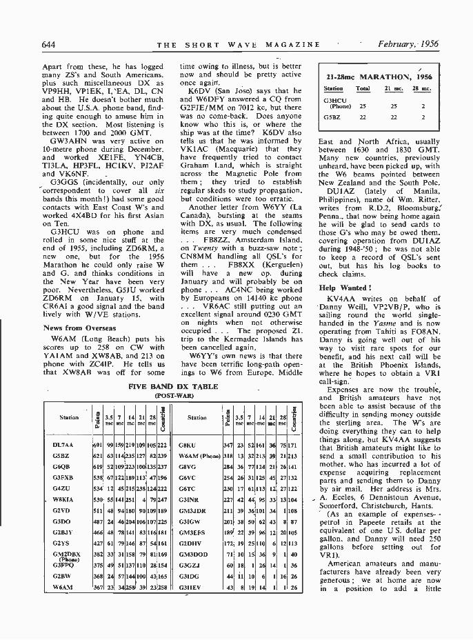
644 THE SHORT WAVE MAGAZINE February, 1956
Apart from these, he has loggedMany ZS's and South Americans.plus such miscellaneous DX asVP9HH, VPIEK, I, EA, DL, CNand HB. He doesn't bother muchabout the U.S.A. phone band, find-ing quite enough to amuse him inthe DX section. Most listening isbetween 1700 and 2000 GMT.
GW3AHN was very active on10 -metre phone during December,and worked XE1FE, YN4CB,TI3LA, HP3FL, HCIKV, PJ2AFand VK6NF.
G3GGS (incidentally, our onlycorrespondent to cover all sixbands this month!) had some goodcontacts with East Coast W's andworked 4X4BD for his first Asianon Ten.
G3HCU was on phone androlled in some nice stuff at theend of 1955, including ZD6RM, anew one, but for the 1956Marathon he could only raise Wand G, and thinks conditions inthe New Year have been verypoor. Nevertheless, G5JU workedZD6RM on January 15, withCR6AI a good signal and the bandlively with W/VE stations.
News from OverseasW6AM (Long Beach) puts his
scores up to 258 on CW withYA1AM and XW8AB, and 213 onphone with ZC4IP. He tells usthat XW8AB was off for some
FIVE
time owing to illness, but is betternow and should be pretty activeonce again.
K6DV (San Jose) says that heand W6DFY answered a CQ fromG2FJE/MM on 7012 kc, but therewas no come -back. Does anyoneknow who this is, or where theship was at the time? K6DV alsotells us that he was informed byVK1AC (Macquarie) that theyhave frequently tried to contactGraham Land, which is straightacross the Magnetic Pole fromthem ; they tried to establishregular skeds to study propagation,but conditions were too erratic.
Another letter from W6YY (LaCanada), bursting at the seamswith DX, as usual. The followingitems are very much condensed... FB8ZZ, Amsterdam Island.on Twenty with a buzz -saw note ;CNBMM handling all QSL's forthem ... FB8XX (Kerguelen)will have a new op. duringJanuary and will probably be onphone ... AC4NC being workedby Europeans on 14140 kc phone... VR6AC still putting out anexcellent signal around 0230 GMTon nights when not otherwiseoccupied ... The proposed ZLtrip to the Kermadec Islands hasbeen cancelled again.
W6YY's own news is that therehave been terrific long -path open-ings to W6 from Europe. Middle
BAND DX TABLE(POST-WAR)
Station gO.
3.5me
7me
14mc
21mc
28mc
.5
3
Station A1L
3.5mc
7mc
14mc
211 28mc me
4"
3
DL7AA 691 99159 219 109 105 222 G8KU 347 23 52 161 36 75171
GSBZ 621 63114 235 127 82 239 W6AM (Phone) 318 13 32 213 39 21 213
G6QB 619 52 109 223 100 135 237 G8VG 284 36 77124 21 26141
G3FXB 538 67 122 189 113 47196 G6VC 254 26 31 125 45 27 132
G4ZU 534 12 45 215 238 124 222 G6TC 230 17 61 113 12 27122
W8KIA 530 55 141 251 4 79 247 G3INR 227 42 44 95 33 13 104
G2VD 511 48 94180 90 109 189 GM3JDR 211 39 36101 34 11108
G3DO 487 24 46 204 106 107 225 G3IGW 201 38 50 62 43 8 87
G2BJY 466 48 78141 83 116 181 GM3EFS 189 22 39 96 12 20 105
G2YS 427 61 79146 87 54161 G2DHV 172 19 25110 6 12113
GM2DBX 382 33 31158 79 81 169 GM3DOD 71 10 15 36 9 II 40(Phone)
G3FPQ 375 49 51 137 110 28 154 G3GZJ 60 18 1 26 14 1 36
G2BW 368 24 57 144 100 43165 G3IDG 44 11 10 6 1 16 26
W6AM 367 23 34258 39 23258 G3HEV 43 8 19 14 1 1 26
21-28mc MARATHON, 1956Station Total 21 mc. 28 mc.
G3HCU(Phone) 25
G5BZ 22
East and North Africa, usuallybetween 1630 and 1830 GMT.Many new countries, previouslyunheard, have been picked up, withthe W6 beams pointed betweenNew Zealand and the South Pole.
DU1AZ (lately of Manila,Philippines), name of Wm. Ritter.writes from R.D.2, Bloomsburg,Penna., that now being home againhe will be glad to send cards tothose G's who may be owed them,covering operation from DUI AZduring 1948-'50 ; he was not ableto keep a record of QSL's sentout, but has his log books tocheck claims.
Help WantedKV4AA writes on behalf of
Danny Weill, VP2VB/P, who issailing round the world single-handed in the Yasme and is nowoperating from Tahiti as FO8AN.Danny is going well out of hisway to visit rare spots for ourbenefit, and his next call will beat the British Phoenix Islands,where he hopes to obtain a VR1call -sign..
Expenses are now the trouble,and British amateurs have notbeen able to assist because of thedifficulty in sending money outsidethe sterling area. The W's aredoing everything they can to helpthings along, but KV4AA suggeststhat British amateurs might like tosend a small contribution to hismother. who has incurred a lot ofexpense acquiring replacementparts and sending them to Dannyby air mail. Her address is Mrs.A. Eccles, 6 Dennistoun Avenue,Somerford, Christchurch, Hants.
(As an example of expenses-petrol in Papeete retails at theequivalent of one U S. dollar pergallon, and Danny will need 250gallons before setting out forVR1).
American amateurs and manu-facturers have already been verygenerous ; we at home are nowin a position to add a little
Volume XIII THE SHORT WAVE MAGAZINE 645
encouragement on our own.
R.E.F. ContestThe R.E.F. notify us that their
1956 Contest will run from March3, 1200 GMT, to March 4, 2359GMT (phone section), and fromApril 14 to 15, similar times (CWsection). The code to be inter-changed is the RST (CW) or RS(phone) plus the serial number ofthe QSO. French stations identifytheir REF Section by figures, andprovince or country by letters.
This Contest provides a goodopportunity for working FrenchProvinces (DPF Award) andFrench Union Countries (DUFAward). Logs to. be sent to REF.Box 42-01, Paris R.P., and willqualify for DPF and DUF countswithout subsequent forwarding ofQSL's.The WBC Certificate
In December we announced theWBC (Worked British Counties)Certificate (see p.541 of that issue)for the benefit of overseas readerswho have worked 50 or moreBritish Counties on any band.
Already we have four success-ful applicants, as follows:
No. 1 : OZ2NU (Aalborg)2 : F9IL (Aubencheul)3 : ON4IB (Bruges)4: ZB2I (Gibraltar)
Certificates are being despatchedto these claimants as soon as theyare ready, and we await a spate offurther applications.
We are glad to credit OZ2NUwith the first one, because he hasbeen asking us for years to pro-duce something of the sort, and itis only fitting that he should reapthe earliest possible reward!DX Strays
The following come from all theusual sources, including the WestGulf DX Club, North and SouthCalifornia DX Clubs, KV4AA andArabackle Oblifork.
VP1AA is active again after along spell off the air ; look around14001 kc ... W4FMK/VP5 ison Caicos Islands ... AC5PNis still active on CW, 14050 kc
. . AC5PL is also reported, butwe understood that 'PN was theonly one there.
KG1KK has been causing somemomentary heart-flutterings, butof course he is only in OX -land
. . KW6BV is reported on
21070 kc ... VS5EW soundsgood, but is he?
Danny of VP2VB/P (see earlierparagraph) is at present FO8AN.He should be on from VR1 inFebruary, after which there is apossibility of operation fromNauru and Timor.
VR2CB has been worked byW's on 7018 kc (1100 GMT) .. .FB8ZZ worked them very fre-quently, mostly around 1600-1800GMT, 14030 kc or thereabouts.. LU3ZY is on the SouthSandwich Islands - 14100 and14060, but call 20 kc below hisfrequency ... A new op. atZS2MI is putting Marion Islandback on the air, Tuesdays,Wednesdays and Fridays at 1700GMT, 14 mc band.
YJ1DL is active again - 14003kc, right at the edge ... VS9GVis putting Aden on the phone map... DU7SV and JA9AA havebeen active on Forty .. .
ZC5GN, if you heard him, wasgenuine - operated by VS1GNduring a vacation ... FP8AK/VP2 will probably be on the airduring the first week-end of theARRL Contest.
VPSDC is on Grand TurkIsland, together with VP5GB .. .
ex-VP5BM is now VP2LH, St.Lucia (Windward Islands).Shorts
G5BZ has at last pipped G6QBfor second place on the Five -BandLadder. G6QB plans a three-element rotary for 7 and 3.5 mc tofill in some of the gaps!
Talking of rotaries, the lastsentence in G3FPQ's letter is " Mybeam has just blown down! "Hard luck, but he will be QRTuntil March in any case, and we
foresee a brighter and better onewhen he returns home then.
G2YS (Filey) tells us that theWAE II, for which he has quali-fied, brings in DL QTC for a year.Antarctica - and More DX
The U.K. element of the Trans -Antarctic Expedition will use thebase station call VRN, on a num-ber of frequencies between 3.5 and20 mc, running an R.A.F. T.1509at 350w. input. Two members ofthe party, including Sgt. Williams,R.A.F., who is i/c the radio side,intend to operate on the amateurbands, calls allocated by the Falk-land Islands Govt. being VP8AOand VP8BO. Sgt. Williams(VP8BO) will erect rhombicsbeamed on Port Stanley, Cape -town and, possibly, the U.K., andexpects to start up in March orApril. The amateur channel willbe Twenty (14025 kc) and perhaps21 mc as well ; most of the trafficwill, of course, be on " official "bands, amateur operation onlybeing as time permits.
For sledging parties and trackedvehicles operating locally, theExpedition is also provided withMarconi HP31 portable trans-mitter/receivers, running about 25watts ; these will be identified bythe call VRN followed by anumber.
Call -signs of the m.v. Theron,the Expedition's supply andtransport ship, is VGWW. It isprobable that the schedule out-lined above will be somewhatdelayed because, at the moment ofwriting, the Theron is in difficultiesin the pack ice, which has alreadymade her some weeks late.
For much of this informationwe are indebted to G3GYI, to the
ARRL DX COMPETITIONPhone Section: February 11, 0001 GMT to February 12, 2359 GMT.
March 10, 0001 GMT to March 11, 2359 GMT.
CW Section: February 25, 0001 GMT to February 26, 2359 GMT.March 24, 0001 GMT to March 25, 2359 GMT.
U.S.A. stations send RST (or RS) report followed by an abbreviatedform of their State, e.g., Vt, Vermont ; Wva, West Virginia. Otherstations send RST (or RS) followed by three figures denoting their inputin watts (025 for 25, and so on).
Three points for each complete QSO, multiplier the number of W andVE licensing areas (19 in all) worked on each band. No " quota " forDX stations ; U.S.A. and Canadian stations are limited in the numberof stations per country that they are allowed to work in each band.
The rules in full appear in the January, 1956, issue of QST.

646 THE SHORT WAVE MAGAZINE February, 1956
BBC, the Expedition's Hq. nearthe office and to QRV of theR.A.F. Amateur Radio Society, ofwhich VP8BO is a member. What-ever may befall, all who read thiswill envy VP8AO and VP8BOtheir opportunity for high adven-ture. Look out for their calls!
From the American party, alsoin the Antarctic just now, weexpect a spate of activity with thecalls KC4USA, 4USB, 4USN andothers in this sequence. Inciden-tally, these very same calls wereused by one of the Byrd expedi-tions before the War - in themid -thirties, we should say. Wewell remember hearing KC4USAfrom Little America on the 14-mcband. The earlier Byrd Expedi-tion, in 1928, made use of theamateur bands for handling traffic
back to the States, but we are notsure, at this distance of time, ofthe call -signs or the frequencies,as our file of QST for those yearshas suffered the depredations ofmice in the attic! From what oneremembers, the Amateur Radioside of the first Byrd Expeditionwas not highly organised, butcertainly the original KC4USAbecame very well known - inthose days Antarctica was realDX.
The 1956 MarathonSo far, only two entries are to
hand for the 21-28 mc Marathon,but they are sufficient to start itoff and we hope to see many moreby next month. Simply send inyour three figures - countriesworked on 21 mc, countries
worked on 28 mc, and totalnumber of different countriesworked over the two bands.
That seems to cover everythingfor this month, so we will sign offuntil we see you again onFebruary 17, first post, which isthe deadline for the March issue.Will overseas readers please notethat it will be March 16, for April.Send all your news and commentsto " DX Commentary," ShortWave Magazine, 55 VictoriaStreet, London, S.W.1. Please bepunctual with them - we aresuffering from an increasing num-ber of stragglers who just miss theboat each month, and it is notpossible to hold copy open a daylater than the schedule. Untilthen, very 73, BCNU and GoodHunting.
REMOTE COMFORTFRED TRIES IT
By G3Coi
THE country was in the grip of winter. Itcoldest that Fred could remember, and, as he sat
in his wicker chair dressed like a motor -cyclist, hepondered on his discomfort, whilst wiping from thereceiver the steam on the dial caused by his breath.Even with the power amplifier going full blast, thetemperature in the roof shack was lethally cold, anda foul-smelling paraffin stove did nothing to relievethe condition. The stove was quite a good one,actually, but suffered from neglect and needed a goodcleaning, a new wick and plenty of paraffin. Asthere was little in the reservoir and the wick wasuneven, it emitted visible and powerful fumes whichswirled through the atmosphere like mustard gas.Strangely enough, Fred rather liked this, because hehad been a D/F operator in the RAF, where manya lonely vigil in a D/F hut had been maintained tothe fug from a paraffin stove ; in Fred's opinion,once one had been " fumed " to it, one had to keepit up, like a drug addict. He used to tell sprogoperators that when they received their Servicedischarge they would draw one dozen tins ofcompressed paraffin -stove fumes with which to keepthemselves going in the first uncertain days of theirreturn to civilian life, until they could get a stove oftheir own. All the D/F operators would make a lotof this story (which, we hasten to explain. was onlya joke), but many of them, nevertheless, on leavingthe Service instinctively plumped for this form ofheating when first setting up house, and Fred was noexception. During the long winter months he wouldkeep his going on the minimum of fuel and wouldnever allow the flame to die out. He would maketea on it, putting on the kettle about fourteen hours
in advance. He made toast on it-strangely-patternedtoast, rock hard in texture, with an unmistakable tangof paraffin. And in the meanwhile, above, below,outside, inside and ubique, as our old -soldier grand-father would say, there hung an abominable stink-a pong that defied description or extinction ; a foul
would have outlasted Hiroshima. Ofcourse, it impregnated Fred's clothing thoroughly,and although he worked at an office, he " smelt likehe worked at a gararge," as our W friends would say.Anyhow, when he retired that freezing night hedecided that perhaps there was something to be saidfor remote control, whereby one could sit by thecheerful glow of one's hearth with the mininum ofgear and work DX with one hand whilst eatingbuttered crumpets with the other and keep an eye onthe pulchritudinous gyrations of the TelevisionToppers.
He fell into a pleasant sleep, dreaming about theTelevision Toppers.
The next evening he collected all his magazinestogether and set about searching for information onremote control. He found out very little, because itis a subject that has not been covered to any greatextent, so perforce he was driven to Evolving anOriginal Scheme. His first notion was an elaborateone, incorporating small electric motors which wouldturn the knobs on the receiver, VFO, and so on, buthe rejected this, as he had no electric motors. Next,he considered having a friendly short-wave listenerwho could sit in the shack and receive telephonedinstructions to move up and down the band asrequired. But he could not remember knowing afriendly short-wave listener.
Finally, he hit on the dull and obvious schemeof moving the receiver downstairs, together with along mike lead, a long VFO switch lead, a longPA HT switch lead, a long exciter HT switch leadand a long AC mains lead, until he had a veritablecascade of cables festooning from the top to the

Volume XIII THE SHORT WAVE MAGAZINE 647
bottom of the house. His mother viewed this activityin hostile silence for a while, then left the house tovisit her sister, who had become accustomed toreceiving such calls, wherein Amateur Radio and allthose engaged in it were torn verbally to shreds.
Fred, inured to such prattle, settled himself downin his armchair by the fire, with the receiver restingon his knees and the various switches adorning hisperson. He tuned round the eighty -metre phoneband looking for his VFO, sorted out the strongestwhisker and embarked upon his usual marathonCQ call. It was just after TV had finished, so therewere many QSO-starved hams about, and he soonbecame engaged in combat.
He was thoroughly enjoying himself when, afterturning it back to his opponent at the end of aparticularly long and boring over, he was annoyedto hear the fellow in contact with a third party,whom he was telling that Fred had inexplicablygone QRT.
Fred hurriedly fumbled his gear to the transmitposition and put out a long call. He achievednothing, so decided to go and investigate. As hepushed open the trap-door to the shack, he wasenveloped by a cloud of smoke which could onlyhave come from burning transformer varnish ... .
The next night, he was back in his wicker chair,dressed like a motor -cyclist, and the weather wascolder than ever. We heard him telling G3XIX orsome other famous DX man that remote control was
. . . Dressed like a motor cyclist . . . .
all right for those who liked to keep the familycompany, but a true ham missed the friendly glimmerfrom his rig, the hum from the mighty transformers,and the occasional belt from an unearthed powerpack....
NEW YEAR HONOURSIn Her Majesty's New Year Honours List,
published on January 2, several distinctions werebestowed in the sphere of radio communication andelectronics. Brig. R. Gambier -Parry, retiring directorof communications, Foreign Office, is made K.C.M.G.The honour of C.B. goes to A/Cdre. W. E. G. Mann(Signals. R.A.F.), who is now director-general, navi-gational services, Ministry of Civil Aviation, and toW. J. Richards, Esq., director of the Radar ResearchEstablishment, Ministry of Supply. Capt. C. F.Booth, assistant engineer -in -chief, Post Office, is madeC.B.E. The M.B.E's in the List are R. G. Hodges,senior experimental officer, Radar Research Estab-lishment, Ministry of Supply, and G. E. Randall,radio officer, s.s. Scottish Hawk.
CALL BOOK, WINTER EDITIONThe Radio Amateur Call Book, published quar-
terly, is the only complete directory to the radioamateurs of the world. Recent issues have run towell over 500 pages, in three columns of close print,and the Call Book also contains much data ofpractical value to the DX operator. In the latest(winter) edition, there are 67 columns of U.K. call-sign/addresses, including all those published in our" New QTH " feature up to and including theNovember 1955 issue of SHORT WAVE MAGAZINE. TheCall Book is available in two versions - the FullEdition, and the Abridged Edition, the latter omittingonly the American listings, which run to approxi-mately 350 pages. The Radio Amateur Call Book,
in either edition, is available from our PublicationsDept., prices as advertised. As we are sole U.K.and European agents for the Call Book, orders canusually be filled from stock.
INDEX, VOLUME XI IAs this issues of SHORT WAVE MAGAZINE concludes
our 13th volume, a complete Index to it, as a freeloose supplement, will be included in every copy ofthe March issue, which will be No. 1 of Vol. XIV.
RADIO AMATEURS' EXAMINATION - MAYThose intending to take the next Radio Amateurs'
Examination, in May, are reminded that theirapplications must be in before March 31. Fulldetails can be obtained from the local TechnicalCollege or the Education Authority (quoting SubjectNo. 55 in the City & Guilds Examination Syllabus)or direct from the Superintendent, Dept. of Tech-nology, City & Guilds of London Institute, 31Brechin Place, London, S.W.7. The examination isarranged to take place at some centre within con-venient reach of the candidate's home. The addressof the Technical College or Education Authority canbe obtained from the local telephone directory.
ADDRESS, PLEASEIf A. H. Parker, 030V, would get in touch with
us (or anybody who knows his whereabouts) hewould, as they say, " hear of something to hisadvantage."
(48 T H I S H u u R T WAVE MAGAZINE February, 1956
Going After DXNOTES FOR NOVICES
PART III
By THE OLD TIMER
Previous articles in this short series appearedin our December and January issues. In thisconcluding instalment, our contributor dis-cusses DX working on the telephony bands.
-Editor.
N this final instalment of our hints to DX -1 chasers, it is proposed to deal with themethods of the telephony fraternity or voice -men. They have something in common withthe CW technique, but not much. For onething, a DX station, if it has a skilled operatorbehind it, can read the calls of several CWstations simultaneously-but that is very diffi-cult with phone on account of the multiplicity«of heterodynes set up. So it usually happensthat the phone DX men spread out rather moreand do not usually call right on the DXstation's frequency.
thing, but it poses the mainproblem - on what frequency do we call ?Obviously if you are calling a W station youwill not go into the U.S.A. phone band to doit-because if he is after DX he won't belistening there, anyway. So the logical thingis to get somewhere near the edge of that band.For instance, a W7 in a State that you havenever worked is calling " CO DX " between14200 and 14300 kc. Unless he announcesotherwise himself, he will probably tune from14200 downwards to about 14100 kc ; so ifyou find a nice clear spot somewhere around14190 kc you have a fair chance. Do not tryto make it right on the band -edge, because thatis where the ORM is usually worst of all.
Some of the more enlightened DX types willmake it more straightforward for you by an-nouncing " and tuning from 14100 up " or" from 14200 down "-and then your courseis clear.
Not Too NearNow suppose some really rare phone station
-a VR5 or a KP6, or someone of that kind-is calling " CO DX " in the DX phone band.Say, somewhere just above 14100 kc, or around21150 kc. Where do you reply if he gives noindication of his listening methods ? Theanswer is to get somewhere near him, but not
too near. If you pitch 10 kc away, and thewhole of the intervening space turns out tobe a mass of phones calling him, you areperhaps more likely to be heard than any ofthe members of that bunch. It is only naturalthat the DX station should tune away from hisfrequency and should stop on the first clearlyaudible voice that he hears. It could be yours.On the other hand, of course, you don't knowwhether he is in the habit of tuning upwardsor downwards from his own frequency, butcareful listening to one or more 'DSO's willprobably tell you which he does-or whetherhe carries them out alternately.
As with CW, it is quite legitimate to listento one of his contacts, to net accurately on thestation he is working (not radiating while youdo this, naturally !) and to chip in with abrisk call as that station is signing off. Butdon't try it before that, or you will find your-self on the " black list."
As the foregoing implies locating yourselfcorrectly in the band of your choice, the tableherewith shows the main CW/Phone divisionsin accepted use at the present time. In theinterests of all concerned, it is highly desirablethat this segregation should be maintained, asit gives both the CW men and the phoneoperators the best chance of making the con-tacts in which they are interested. Strayingshould be severely discouraged ; it would bequite in order to call and warn any phonestation heard in a CW band-the CW fraternitydo not, as a rule, spill into the phone territory,as there is nothing for them to work there,and interference is more troublesome. To thephone man, however, with his BFO out, a CWband often sounds relatively ORM-free !
Short CallsOn phone, as on CW, short calls pay divi-
dends, and you must have a really quickchange -over. Then you can just push theswitch, call " KP6ZZ, KP6ZZ, KP6ZZ, this isG3XYZ, G3XYZ, G3XYZ calling-and listen-ing," or some such formula. If there is noreply you can immediately repeat the wholething, fairly certain that he has not yet repliedto someone else. If you make, the all -too -common mistake of making your call threetimes that length, when you go over to receiveand hear nothing, you won't know whether hehas already acknowledged another station witha quick reply and report.
Short calls, twice or thrice repeated, areinfinitely better than one long one, because youare not deaf all the time-you have a chanceof a quick listen to see what is going on.

Volume X111 THE SHORT WAVE MAGAZINE 649
Quality of SignalAs with CW, the quality of your signal
matters enormously. And here we should liketo say that a dreadful misconception has grownup and spread with the years. Never a daypasses without someone being heard sayingthat " Nice toppy phone cuts through theQRM." And never was anything less true !Most of the audio power is in the lower fre-quencies, and it is the phone with good beefybass that wins every time for readability.QRM itself is toppy ; and if the crystal filteris in use at the DX end, much of the top isintentionally cut - including, possibly, your" nice toppy phone."
A reasonable amount of " top " - up to3000 or 4000 cycles-is highly desirable formaximum intelligibility, but it is only appre-ciated at the other end on a fairly QRM-freeQSO. Under the usual conditions of a DXscramble, with maximum selectivity on thereceiver, the distant chap won't even knowwhether you are radiating top or not ! If youhave what used to be called " nice roundphone "-meaning a transmission with its fullquota of bass, but not devoid of top to theextent of getting the plum -in -the -mouth effect,you have the best type of phonefor working DX.
If anyone tells you that " toppy phone cutsthrough the QRM," ask them to explain why,and exactly how the " cutting " is done. Wehave never heard a satisfactory explanationyet, and certainly can't think of one.Don't Overdo It
Here we should also say that the over -useof phonetics defeats its own object, apart frommaking everything terribly long-winded. Ifyour DX prize is going to hear you anyway,he will get your " KP6ZZ, this is G3XYZ "just as well as anything you can invent in theway of " King Peter Figure Six Zebra Zebra,this is George Figure Three X -Ray YokohamaZanzibar." If he hits that rigmarole in themiddle (and how often is it heard ?) he won'teven recognise a call -sign, whereas you can saythe plain straightforward one three times inthe same number of seconds, and it is recog-nisable at once if your signal is good enoughto get there at all. And as for the simpletonswho solemnly start up with " Hullo, hullo,hullo " ... words practically fail us. Itoccupies time and space, it doesn't give a clueto anybody, and if the DX man does hear ithe will probably pass straight on to the nextchap, who is giving a call -sign by then. It'slike the " Dah-de-dah-de-dah " with which
AMATEURBAND
KNOWNAS
CW/PHONEDIVISION
3500-3800 kcEighty3.5 mc
80 metres
cw: 3500-3600 kcMixed
3600-3700 kcPhone:
3700-3800 kc
7000-7300 kcForty7 mc
40 metres
cw: 7000-7150 kcPhone :
7150-7300 kc
14000-14350 kcTwenty14 mc
20 metres
Cw: 14000-14100 kcPhone:
14100-14350 kc
21000-21450 kcFifteen21 mc
15 metres
cw: 21000-21150 kcPhone :
21150-21450 kc
28000-30000 kcTen
28 mc10 metres
cw: 28000-28200 kcPhone:
28200-30000 kc
NOTE : Agreed American Phone Bands are3800-4000, 7200-7300, 14200-14300, 21250-21450, and28500-29700 kc. Hence, G phones (and most others)should operate in the areas 14100-14200, 14300-14350,21150-21250, and on ten metres, between 28200 and28500 kc, or in 29700-30000 kc.'I
some CW types open every call-means noth-ing, does nothing and reflects on the intelligenceof the person using it.
So go ahead, whether on key or voice, andtry your luck. Luck is an important factor inall DX working, and you can't have it all thetime. When it comes your way, though, makethe best of it and help it along with someintelligent operating. The various contestsscheduled for the next few months will giveyou plenty of opportunity of trying out theprocedures discussed here.
PHOTOGRAPHS ALWAYS WANTEDReaders who have good, clear photographs of
Amateur Radio interest - either equipment, per-sonalities or stations, particularly overseas - arereminded that we are always in the market for printssuitable for publication. Payment is made, onappearance, for all photographs used.
NOTE TO CONTRIBUTORSThose who may feel inclined to offer us articles
for paid publication are asked to read carefully thesummary on the presentation of material, on p.432of the October 1955 issue of SHORT WAVE MAGAZINE.While it is usually better to write in first, or offer asynopsis of the proposed contribution, the notesreferred to give an intending author all the informa-tion he requires to produce an article on any subjectof Amateur Radio interest.

650 THE SHORT WAVE MAGAZINE February, 1956
Adjustment ofOvertone Crystal
OscillatorsIMPROVED CIRCUIT
ARRANGEMENTJ. A. BLADON, B.Sc. (G3FDU)
This article describes an original and ingeniousapproach to the well-known problem of gettingcrystals off at their overtone frequencies. Thewriter shows that by using a small variablecapacity in series with the feed -back winding-which can thereby be made conveniently largerthan the value usually given-it is possibleto adjust the excitation very easily and withabsolute accuracy. By his method, manycrystals normally regarded as inert on theirovertone frequencies can be made to control
in that mode. Editor.
WHILST the use of commercial crystals cutfor overtone work presents little difficulty
in circuit adjustment, considerable trouble isoften experienced when a fundamental -modecrystal is tried in an oscillator on its third orfifth overtone frequency. The feedbackcoupling necessary to produce satisfactory andstable operation on the required frequency isusually very critical. Too much coupling re-sults in oscillation either at the fundamentalfrequency or at a frequency controlled by theexternal constants of the circuit. Too littlecoupling produces no oscillation at all. Theadjustment to the happy mean can often beobtained only after long hours of frustrating" cut and try " methods. The purpose of thisarticle is to suggest means by which the neces-sary " cut and try " can be reduced to aminimum.
One of the earliest and most popular over-tone oscillator circuits used by amateurs is thatdue to Squier (Fig. 1). A triode valve is ar-ranged with a condenser CI and inductanceL1 in the anode circuit tuning at the desiredovertone frequency of the crystal. A few turns
Table of ValuesFig. 2. Improved Overtone CO Circuit
CI/LI = To tune to requiredo/t frequency
CI, C2 = 3-30 µµF trimmerC3 = 100 µµF micaC4 = .001 µF paper
Ll, L2 = See textRl = 10,000 ohmsR2 = 47,000 ohmsV = 0-150v. meter (for
test)X = Xtal
of wire are closely coupled to L1, one endbeing earthed and the other connected to thegrid of the triode with the crystal in series.If the amount and phase of the coupling arecorrect, the crystal will be induced to oscillateat the overtone frequency, the tuned circuit inthe valve anode acting to prevent feedback atany other frequency. If the coupling turns areincreased, a point will be reached at which thecoupling through the capacitance of the crystalholder will be sufficient to maintain oscillationat the resonant frequency of the tuned circuit,even though this may not be at the overtonefrequency of the crystal. The range of coup-ling turns over which correct operating condi-tions prevail is small and can be very difficultto find, even if a Grid Dip Oscillator is avail-able to set the correct values of Cl and LI,and a receiver is used to listen on the outputfrequency.
Simplified ProcedureThe pains can be taken out of the adjustment
procedure if a small preset condenser be con-nected in series with the crystal and the
L
x
HT+
-Output
1
FIG.1 Basicover toneoscillator
circuit
C3 HT+ 200VOutput
C4.r:
FIG.2 Suggested modification
Fig. 1 is the basic Squler circuit, referred to in the text. Fig. 2is the modification suggested by G3FDU and discussed in hisarticle ; it enables the setting for overtone operation to befound much more easily and accurately than by coil tapping.

Volume XIII THE SHORT WAVE MAGAZINE 651
feedback winding as shown in Fig. 2. Thewinding itself should be in the same direc-tion as a continuation of the main winding L1,with the end nearest to Ll taken to earth, theother end being connected to the grid of thetriode valve via the preset condenser C2 andthe crystal, as previously described. Thenumber of turns in the coupling winding shouldbe about one-third the number of turns in themain winding of Ll.
Before the oscillator proper is adjusted it isprudent to test the crystal for activity on therequired overtone. This is easily carried outwith the aid of a Grid Dip Oscillator tuningthe required frequency. Three or four turnsof wire are wound round the tank coil of theGDO and connected to the terminals of aholder containing the crystal to be tested. Asthe GDO is tuned through the overtone fre-quency, a sharp dip should be observed in thegrid current, the depth of this dip giving arelative measure of the overtone activity of thecrystal. Most 6-9 me crystals show satisfactoryactivity on the third overtone when tested inthis manner.
The valve is now placed in the oscillatorwithout the crystal and with the coupling con-denser C2 at minimum, the tuning condenserCl is adjusted with the help of a GDO so thatthe circuit tunes to the correct overtone fre-quency. The crystal is now placed in theholder, the power supplies connected and aftera period of warm-up, the voltage between earthand the anode end of R2 is checked, i.e., acrossC4, as indicated. Coupling condenser C2 isnow carefully increased and a sudden rise inthe measured voltage indicates that the valve
MI NTUNING CAPACITY Cl
!b)
MAX
Fig. 3. Diagram showing correct adjustment of couplingcondenser C2, as explained by G3FDU. Curve (a) representsuncontrolled oscillation, when C2 Is too large ; Curve (b) meansno oscillation, when C2 is too small ; Curve (c) representscorrect operation. The readings are in terms of voltage across
C4 in Fig. 2.
starts to oscillate. The tuning condenser Clshould now be swung around its original set-ting, and if oscillation (indicated by the highvoltage between earth and the anode endof R2) continues, the coupling condenser C2should be slightly reduced in setting. Thecorrect operating condition, in which oscilla-tion is maintained over a very small range ofsetting of Cl, is easily found and is indicatedin the diagram, Fig. 3.
This method of adjustment has proved suc-cessful for many crystals showing activity ontheir third overtones. It has too often beensuggested that operation of fundamental modecrystals on their fifth overtones can only beobtained with difficulty, if at all, but use ofthe above method of adjustment should makethe task considerably easier than before.
MARITIME PROVINCE FLOODSSerious flooding recently in the Maritime
Provinces of Canada, the worst for many years,caused widespread damage throughout Nova Scotiaand a failure in communications. The VEl's wentinto action and in many areas provided the onlycircuits available to the authorities for rescue andsupply work. The Royal Canadian Mounted Policehave acknowledged the assistance given by the radioamateurs of Nova Scotia and New Brunswick.
ELECTRICAL ENGINEERS EXHIBITIONThis is a specialised exhibition, open only to the
trade, and is the industry's shop -window. It takesplace at Earls Court, there will be more than 300exhibitors showing a great range of machinery andelectrical equipment, and the opening on March 20will be performed by the President of the Board ofTrade. The general manager of the ElectricalEngineers Exhibition is P. A. Thorogood, G4KD.
PRICE INCREASE-MARCH ISSUEThe trend of events has caught up with
us and we much regret that, effective withthe next (March) issue of SHORT WAVEMAGAZINE, we are compelled to increaseits cover price to 2s. 6d. Except for oneyear, the price for the last eight years hasbeen held at 2s. In the circumstances, wefeel sure readers will agree that the increaseis fair and reasonable. Direct subscribersare not affected until their renewal becomesdue, and we are prepared to accept newsubscriptions at the present rate of 24s.per annum until March 9, the date ofpublication of the next issue.
652 THE SHORT WAVE MAGAZINE February, 1956
MOST of those who are with usthis month will not need telling
about the extraordinary EDX breakon Two Metres during the eveningsof January 4/5. Fog, which wasparticularly dense in the Londonarea, enveloped most of the country ;the glass stood high and steady, andit was cold, with a clearing sky abovethe fog.
The troposphere was in an idealcondition for low-level refraction-so much so, that some remarkablecontacts were made. To GI3GXP(Kilkeel, Co. Down) goes thedistinction of scoring two brilliant"Firsts," with ON4BX and DL1SEworked on January 5. Manyother excellent QSO's were obtained,as there was quite a high level ofactivity ! Conditions on the 4thwere probably more " open " thanduring the next evening, by whichtime the buzz had gone round,bringing on more stations. Thereports seem to suggest that thearea of good conditions only justextended into the north of England,as the Lancashire stations were notgetting quite the results enjoyed bythose further south. On the otherhand, the latitude of Kilkeel isapproximately that of York, andthe path GI3GXP-DL1SE (Nr.Detmold) is right across Lan-cashire ; the line Kilkeel-Brusselsruns much more in the southerlydirection, over Derbyshire.
Thus we see, once again, thatEDX is entirely possible during thewinter, and that it always pays towatch the VHF bands, no matterhow unpromising the omens. Ithappened that the opening on Janu-ary 5 coincided with the LondonVHF Dinner-owing to the fog,many of those who had intended tobe present could not get there ;but it is said that the attendanceat the Dinner did lessen the QRMin the London area ! (We are notsaying this ; it is what we are toldby correspondents !).
Note on The Contest
Rules for the U.K. Two -BandVHF Contest in March appearedon pp. 590-591 of our last, and manycorrespondents have remarked thatthey intend to be on for it.
Due to a printing error, noticedtoo late, Rule 4(e) needs to beamended to read " Ten points forall stations worked over 200 miles
B
-7_
_Alb- _AIL-
USA. J. DEVON
Big DX Opening, January 4/5-GI3GXP Scores DL & ON
" Firsts "-
F8GH-F8OL work 50 miles on1200 mc Band-
CC Area Proposals for 25 Cm-
Station Reports & News-
(E)." Please make the correctionon your copy (p. 590, January" VHF Bands ") now-and thenthere will be no mistake when youcome to tot up those E -distancepoints !
Other queries on the Rules-What is meant by name ? Christianname or surname ? Answer :Name as usually given over the airin the course of an ordinary QSO-or, if you like, adopt a " name "or nom -de -plume for the purpose ofthe Contest ! Is /P operating reallyallowed ? Answer : Yes, as impliedby Rule 5 any type of amateur VHFoperation is permitted " providedonly the same callsign is usedthroughout the Contest."
Your A.J.D. hopes that all is nowclear-and that you have amendedRule 4(e) as requested.
New Results on 1200 mcFrom the December issue of
Radio -REF we take the news thatF8OL and F8GH have made contacton 25 centimetres over a distance,QTH to QTH, of 50 miles ; it wasactually a cross -band QSO, with
F8OL (Meudon, S -et -O) transmit-ting CW on 1260 mc. His 25 -cmoutput stage is a 2C39A, triplingfrom the 420 mc crystal controlledtransmitter, and gives about 5w.RF out ; allowing for feeder loss,this becomes 2.5 watts at the aerial,which is a corner reflector havinga gain of 16 dB.
F8GH (Glatigny, Oise) the 25 -centimetre receiving arrangement isa coaxial crystal mixer using aIN21B, with a crystal controlledoscillator -multiplier giving injection145 mc below signal frequency,enabling the standard two -metrereceiver to be tuned as secondconverter ; though the noise factorof the receiving chain complete isgiven by F8GH as 11 dB, he doesnot mention exactly how, or withwhat valve types, the injection fre-quency is obtained. The receivingaerial at F8GH is the same as thatused for transmission at F8OL.
A most important point aboutthis QSO-first effected on Septem-ber 22 last, and repeated since-is that the path is not line of sight,or anything like it ; the aerialheight at F8GH is 600 feet, and atF8OL 330 feet, but the interveningterrain is higher than this, and other-wise is broken country. Neverthe-less, the 25 -cm signal at F8GH wasread at S8-9-at about the samelevel as the F8OL signal on twometres-with little fading, and the2C39A tripler gave a sharp, steadyCW note, excellent in every respect.
As F9ND, who contributes theVHF notes to Radio -REF, says inhis report, these results are extremelyencouraging in that they promisethe possibility of amateur contacton 25 cm over paths and distancesbeyond the limit of visibility. Itis also significant that F8OL andF8GH have obtained their resultsusing stabilised equipment, and itis probably safe to say that itwould not have been possible withSEO gear. (Though this readslike a contradiction of the comment,SEO v. CC, in this space last month,the argument still is that while CCequipment should certainly be usedon 25 centimetres by those able todo so, the band can be opened forlocal working using simpler gear).
On this side of the Channel. themost active stations on the 1200mc band known to us are G3CGQand G3FUL, both of Luton, who
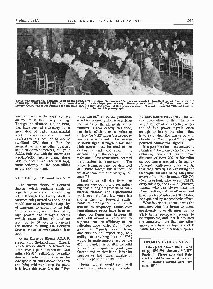
Volume XIII THE SHORT WAVE MAGAZINE 653
Those who braved the elements to be at the London VHF Dinner on January 5 had a good evening, though there were many emptychairs due to the thick fog that came down that night, which kept people away. However, one result of the Dinner was that theLondon QRM was much reduced for the EDX opening that also occurred that same evening ! Several prominent VHF men can be
identified in this photograph.
maintain regular two-way contacton 25 cm at 1830 every evening.Though the distance is quite local,they have been able to carry out agteat deal of useful experimentalwork on receivers and aerials, andG3CGQ is in a position to receivestabilised CW signals. For themoment, activity in other quartershas died down somewhat, but yourA.J.D. feels that with the example ofF8OL/F8GH before them, thoseable to obtain 2C39A's will lookmore seriously at the possibilitiesof the 1200 mc band.
VHF DX by " Forward Scatter "
The current theory of ForwardScatter, which explains much asregards long-distance working onVHF (though the theory itself isfar from being agreed by the pundits)would seem to be beyond the capacityof amateurs to exploit to the full.This is because, on the face of it,high powers and high -gain beams(which mean dishes of anythingfrom 20 to 60 feet in diameter)are needed to bring the ForwardScatter mode of propagation intoaction.
At the Kingston Blount U.S.A.F.station (nr. Stokenchurch, Oxon.),which works direct to Iceland onVHF over a path -distance of 1,200miles with 98% reliability, the radia-tion is directed at a zone in theionosphere 50 miles above the earthand lying mid -way along the path.It is from this zone that the " for-
ward scatter," or partial reflection,effect is obtained ; what is exercisingthe minds of the physicists at themoment is how exactly this zone,not fully efficient as a reflectingsurface for VHF waves but neverthe-less usable, is formed. It is becauseso much thathigh power must be used at theoriginating end, and since it isessential to get the energy into theright area of the ionosphere, beamedtransmission is necessary. Thewhole technique may be describedas " brute force," but without theusual concomitant of " blurry ignor-ance " !
Looking at all this from theamateur view -point, and remember-ing that a long programme of com-mercial research and experimentalwork over the last few years hasshown that the Forward Scattermode of propagation is not muchaffected by frequency-results overlong-distance paths have been ob-tained on frequencies between 30and 3000 mc-it is reasonable tosuppose that the efficiency of thereflecting zone varies from " verygood " to " pretty poor." Now,amateurs do not expect 98 % reli-ability, or anything like it -50would be quite acceptable ; on the430 mc band, it is possible to builda beam with quite a good gainfactor ; and on that band, it is alsopossible to find valves capable ofefficient operation at full input.
From this, it would seem wellworth while attempting to exploit
Forward Scatter on our 70 -cm band ;the probability is that the zonewould be found an effective reflec-tor of low power signals oftenenough to justify the effort-thatis to say, when the scatter zone isclassified as " very good " for high-
It is possible that those amateurs,British and American, who have beenobtaining consistent results overdistances of from 200 to 500 mileson two metres are being helped byForward Scatter-in other words,that they already are exploiting thetechnique without being altogetheraware of it. For instance, G2HCG(Northampton), who works PE1PLevery mid -day, and G3GPT (Preston,Lancs.) who can always hear theDutch station, and has often workedhim. Such consistent results cannotbe explained by tropospheric effects.
What is certain is that it was theamateurs who first began to work,consistently, over distances on theVHF bands previously thought tobe impossible, and that it has beenthe amateurs, more than any otheragency, who have developed the VHFbands for communication purposes.
TWO -BAND VHF CONTESTTakes place March 10-11, rules
on pp. 590-591, January " VHFBands." Please note that Rule4 (e) should be amended to read". . . stations worked over 200miles (E)."
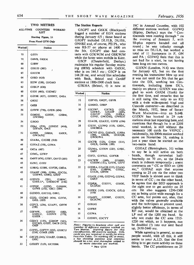
654 THE SHORT WAVE MAGAZINE February, 1956
TWO METRESALL-TIME COUNTIES WORKED
LIST
Starting Figure, 14
From Fixed QTH Only
Worked Station
75
70
68
66
65
64
63
62
60
39
38
57
56
55
34
53
52
so
49
48
47
46
45
44
43
42
41
40
39
38
37
36
35
34
33
G5YV
G6NB, G6XM
G3BW
G3IUD (302)
G3CCH
GSBD (435)
EI2W (258), G3GHO
G3BLP (630)
020I (402), G3DMU
G2FJR (427), G3EHY, G4SA
G8OU
G8SB
G3WW (770), GSDS (654)
G2HDZ, 0211IF, GSBM,GW5MQ
03100G2AJ (519) G2HDZ (416),
G3FAN, (;4CI
G2NH, G6RH, G6XX,GW2ADZ
G3ABA, G3GSE (518)
G3HAZ (358), G5MA
G6TA (487)
G5ML, GSWP
G4HT (476), G5BY, G6YU (205)
G2XC, GSJU
G3BJQ, G3BK, G3FIH, G8DA
G2AHP (500), G3BA, G3CO3,G3HWJ, G4RO, GSDF
G2DVD (291), G3BNC,G3DLU, GM3EGW (146)
G2FQP, G3DO, G3HBW,G3WS (255), G6CI (184)
G2DDD, G3CGQ, G8KL
G2IQ, G3GBO (434), G3VM,G8IL (325)
G2FCL (234), G3APY, G8VN(190)
G2FNW, G2FZU (180),G3DLU, G3DVK (175),G31ER
G2DCI (155), G2HOP (161),
08G3CXD, G3IIT, G6CB (312),
G3FZL, G3FYY (235), G3HCU(224), GSMR (305)
G2CZS (243), G3AEP, G3BKQ,G8IC
G3HHY (1251, GC3EBK
The Station ReportsG3GPT and G6KK (Blackpool)
logged a number of EDX stationsduring January 4/5 ; those heard atG3GPT included DLILB, DLISE,ON4BZ and, of course, PEIPL, whowas RS -57 on phone at 1400 onthe 5th. G3GPT also had con-tacts with G5KW/M and G8KW/Mwhile the latter were mobile in Kent.
G5CP (Chesterfield, Derbys.)maintains his regular Sunday morn-ing (0830) schedule with G6XM,who is on 144.5 me ; G5CP is on144.28 mc, and would like scheduleswith Bath, Bristol and Cardiffstations at 1800-1900 clock time.
G3KHA (Bristol, 4) is now at
Worked Station
32 G2FVD, G8QY, G8VR
31 G3HXO, GSRP
30
29
28
27
26
25
24
23
22
21
20
19
18
17
16
15
14
G2CIW, G3CKQ (122),G3FRY, G3GOP (208),G3GVF (129), G3IRA,GSNF, GM3D1Q, GW8UH
G3AGS, G3AKU, G3FU (194)
G3ITF, G3JWQ (135), G8DL,GM3BDA
G3CVO (231), G3DAH, G3ISA
GW3GWA6GR,GI3GQB,
G3CFR (125), G3SM (211),G4LX, G4MR (189)
G3JMA, G3JXN (220), GSSK,G6PJ
G3FD, G3FXG, G3FXR
G3CWW (260), G3HSD,G3JHM (131), G3YH, G5PY
G2DRA, G3AGR (135), G3ASG(150), G3BPM, G3HIL,G5AM, G8NM
G2AOL (110), G3DVQ, G3IWJ,G6XY
G2BRR, G3EYV, 0310E,GC2FZC
G3FEX (118), G3GCX, GSLQ(176)
02AHY, G3DBP, G3JOY,GC2CNC
G3EGG
G3FRE
G3IWA
G2DHV, G3CYY
Note: Figures In brackets alter call arenumber of different stations worked onTwo Metres. Starting figure for thisclassification, IM stations worked. QSLcards are not required to verify for entryinto this Table. Onworking 14C or more.a list showing stations and countiesshould be sent. and thereafter added to
as more counties are worked. New QTH
19C in Annual Counties, with 102different stations worked. G3JWQ(Ripley, Derbys.) says the " Con-tinentals were roaring through " onthe evening of January 5, withS9 -plus reports handed out allround ; he was unlucky enoughto miss on DLILB, but worked atotal of II Europeans in F, ONand PA ; G3JWQ feels that this isnot bad for a start, he not havingbeen long on two metres.
G3JXN (London, N.6) was therefor January 4/5, but on the firstevening his transmitter blew up andit was not until the 5th that he gotinto the DX, working ten Con-tinentals, including three DL's,mainly on phone ; G3JXN was alsoglad to work G6XM (York) forthe first time, and remarks that heis still using lOw. only to an 832with a 4 -ele wide -spaced Yagi andCascode converter -as described inthe March, 1952, issue of SHORTWAVE MAGAZINE -into an S.G31XN has booked in 29 nestations since last reporting here, andmentions that though he is at 220Stotal worked, is still without thenecessary 100 cards for VHFCC ;incidentally, his 200th station workedcame on November 16, making itjust a year since he started on thetwo -metre band.
G3HAZ (Birmingham, 31) writesto say he is still active on bothbands, though somewhat half-heartedly on 70 cm, as the 24 -elestack is indoors temporarily ; anentcomments on " CC or SEO on 1200mc," G3HAZ says that anyonecoming to 25 cm via the other twoVHF bands is almost sure to thinkin terms of CC ; on the other hand,he agrees that the SEO approach isthe right one to get activity on 25cm. He also suggests 1296-1300mc as being quite wide enough for aCC area, but points out, also, thatwith the valves generally availableand the techniques at present used,slightly better efficiency, in terms ofRF out, would be obtained at theLF end of the 1200 mc band. Sowhy not make the CC area 1215-1220 mc which, as it happens, canbe doubled (I) into our next bandup, 2430-2440 mc.
While agreeing in general, as mostpeople would, with all this, it stillseems to your A.J.D. that the firstthing is to get more activity on thesebands. The CC practitioners on 25

Volume XIII THE SHORT WAVE MAGAZINE 655
cm will in any case appear at theHF end because they will do thelogical thing by multiplying upfrom the 430 mc band.
G2DVD (Slinfold) has devotedhimself to the design and construc-tion of a new, low power, reallyefficient and TVI-proofed trans-mitter ; operating with 12w. input,results have been very satisfactory.An 829B PA, running 80w. input,is now added, and reports comparevery favourably with the 120w.transmitter previously used.
G3IEX (nr. Woodbridge, Suffolk)has yet to work his own county andNorfolk for the Annual, and reportsG3JKT/A of Brightlingsea as a newstation on for Essex. G3WW(Wimblington), unable to get toTown for the VHF Dinner onJanuary 5 because of the fog, spentthe time profitably on the two -metre air, and worked a number ofEuropeans, DJIMV being missedafter a call from him ; on the 4th,
TWO METRESCOUNTIES WORKED SINCE
SEPTEMBER 1, 1955Starting Figure, 14
From Home QTH only
Worked Station
38
32
31
29
28
26
24
23
21
20
19
18
17
16
14
G3GPT
G3JZG
G3WW
03I00, GSBM
G3JWQ
G2DVD, Ci3FIH
G3DLU
G8VN
G3CKQ, G3DO, G3JXN
G3BJQ, G3HWJ, G5DS
G3KHA
G3IEX, G3WS
G3ITF
G3BW
G31RA
This Annual Counties Worked Tableopened on September 1st, 1955 and willrun for the 12 months to August 31st.1956. All operators who work 14 or moreCounties on Two Metres are eligible forentry in the Table. The first list sentshould give stations worked for thecounties claimed ; thereafter, additionalclaims need show only counties workedas they accrue. QSL cards are not re-
quired for entry in this Table.
Meeting of the JA1's who are on VHF, mainly 50 mc (6 metres), photographed recentlyin Tokyo. On the extreme left is JAIAG, awarded our VHFCC Certificate this month ;the first JA to gain it was JALAN (No. 179), fourth from the left in the front row. Itwill be noticed that the group is seated at table Japanese fashion, making an unusualpicture. In addition to JA1AG and JAIAN, others present are 1AI, 1BB, IDI, IDS,1DW, 1EE, 1FC and 1FL. JAIAG's own caption to this photograph was " JA1's VHFmans, now in boom on 50 and 144 mc." Well, what he meant by that is clear enough.
DL1SE (who was operating asDL1SE/A for part of the time) wasa good contact, and West CountryG's were also wcrked, thoughG2ADZ could not make himselfheard at G3WW, who at the timewas a good signal in North Devon.The evening of January 6 producedmore G contacts, but by then con-ditions had reverted to normal, andthe EDX was gone.
VHF Mobile RecordIt will already have been inferred
from the foregoing that the " KWTwins," G5KW and G8KW, wereout mobile on two metres duringthe period. They worked a numberof stations, and had some good DXcontacts ; of these, the outstandingone is the mobile QSO made byG5KW/NI with EI2W in Dublin,when Ken was at Well Hill, Kent,the distance being about 320 miles.This is probably the " world mobilerecord " for two metres, and wasmade on the evening of January 4.
G2DDD (Littlehampton, Sx.) re-minds us of the third D in his call -sign, often left out of the listsinadvertently because of the slightconfusion with that other activecall G2DD. G2ADZ (Woola-combe, N. Devon) writes that though
he often has to go a week withouta QSO, he works a consistentschedule with G3GPT at 195 miles ;G2ADZ also keeps a week-endschedule with EI4E, and will re-sume the GC2FZC regular contactas soon as the latter has finishedhis rebuild. G2ADZ is there during1800-2000 clock time every evening-and he is also planning some Trans -Atlantic listening tests on twometres, of which he promises furtherinformation when the details arefixed.
G2CIW (Cambridge) has beenbuilding for 70 cm, and found timeto be on during the evening ofJanuary 5 ; on 430 mc, his receiveris a crystal mixer into an EF91 asIF amplifier, with 24-30 mc tunedon the AR77 ; the PA is a QQVO3-20tripler and the beam an 8 -ele stack.
G3BA (Sutton Coldfield) mentionsa simple and very effective methodof neutralising QVO6-20's : A small
in. diam. two -turn coil, widespaced, connected from screen toearth through a Philips trimmer ;a stable neutralising adjustment canbe found very quickly. The samemethod goes for tetrodes such asthe 5763. On 70 cm, G3BA has beentrying QQVO6-40's and QQVO3-20's, also the CV53 as found in the

656 THE SHORT WAVE MAGAZINE February, 1956
Type 105 Unit ; he recommendsthe latter valve as a very efficienttripler.
Items from Overseas
With his fine GI contact onJanuary 5, ON4BZ not only sharesa " First " with GI3GXP, but alsogoes to 15 in Countries worked ;Guy reports that with him theopening was exceptional, in thatnot only many G's, but also DL's,were worked " with fantasticQRK's." He says that YU2CF andYU2DV are both active on twometres and can work into Italy, andthat they have heard, but not yetworked, the only HA on the 144 mcband ; other interesting Europeansknown to be on are OE9BF and9S4AL in the Saarland.
JA IAN (Tokyo), the first Asianto gain our VHFCC Certificate,sends a photograph of the certificateas framed in his shack, and saysthat there are about a hundred JA'sactive on the two -metre band, withthe same number on 50 mc (6metres) ; some of these stations usevery high power, up to a kilowatt,though most have an 832A or 829Bin the PA ; otherwise, gear is con-ventional and much as used in thiscountry, with stacked Yagis forbeam arrays. Their 6 -metre band is50.0-51.8 mc, and for two metresthey have 144-147 mc.
F3SK (Asnieres, Seine) devotes allhis attention to the bands 72 to1260 me inclusive, and comes downheavily on the side of G3JHM inthe discussion (last month) about" putting SEO to rest " and defininga narrow band of frequencies forCC operation on 25 cm ; F3SKsays the present situation is " an-archical," with people building gearfor 1215, 1250, 1260 and 1296 mc !While, as F3SK points out, it is
easy enough on the transmitter sideto choose a frequency and go aheadon it, matters are not so simple inreception, as the receiver can onlycover a relatively narrow bandeffectively.
This is all good argument andthe only problem is : Where is theCC band to be ? G3JHM suggested1296-1300 mc, because of the har-monic relationship with our 432-438mc area on 70 centimetres. F8OL,in discussion with F3SK, suggests1260-1262 mc, because its harmonicrelationship suits the French bandallocations ; and the DL's are saidto be considering a narrow bandround 1250 me !
Clearly, whatever the band is to beit should be defined, adopted andadhered to on a European basis -and it wants settling quickly. Accord-ing to our information, the" European VHF Managers"touched upon, but did not in anyway settle, this particular problemduring their recent week-end inBrussels.
Incidentally, for the informationof those interested, the followingF's are on 70 centimetres everySunday at 1400 GMT, calling CQon CW and phone, with beamsheaded N -NW : F3JN, 434.92 ;F3SK, 435.05 ; F8MX, 434.70 or435.25 ; F8OL. 435.00 ; and F3FS.F8LO and F9TV slightly below435.00 mc.
Another JAI to claim VHFCCis JA1AG, Kawasaki, whose Certifi-cate will be numbered 191, andwhose claim will be discussed in ournext, with others received since thelast list appeared.
Some SWL Reports
SWL Ball (Hutton, Essex) madethe most of the January EDXopening, some of the Europeans
and DX G's heard being so strongthat he was able to tape-record them(to listen to when the band is dead,no doubt !). SWL Drybrough(Coventry) got his share during theopening, too, and is now givingtime to an improved aerial andconverter.
From Malvern, SWL Tomlinwrites that during his three yearsof listening on two metres, he hasoften heard strong signals in thewinter from GDX distances, whenthe temperature was below freezingand the band activity low ; duringthe last six months of 1955, his logtotals, of different stations heardeach month, are : July, 124 ; August,114 ; September, 87 ; October, 82 ;November, 81 ; and December, 55.During the January opening, SWLTomlin made a personal call onone G station to tell him the bandwas alive ; said station went on theair and worked three PA's !
SWL Cox (London, S.W.18) agreesthat the band is never as dead as itsounds, but says you've got to digfor them, all the same !
Held Over -With the VHFCC claims are
various other items of interestfrom different sources, which willhave to keep till next month. YourA.J.D. has been more than somewhatpressed for this issue, but has, never-theless, been able to cover all thecorrespondence.
Don't forget about the Contestweek-end, March 10-11, and in themeantime, please let us have allyour VHF news and views byMonday, February 20 certain,addressed : A. J. Devon, " VHFBands," Short Wave Magazine,55 Victoria Street, London, S.W.1.With you again on March 9, whichgives us a little more time than wehave had the last month or two.
FREQUENCY COVERAGE - N.Z. ZCIEQUIPMENT
The Mark I version of this equipment-the N.Z.ZC I Mk. I-covers only the 80 -metre amateur band.It is the Mk. II that gives coverage of the threebands 160, 80 and 40 metres, with an LF tuning limitof about 1900 kc. The only meter fitted in the ZC1equipment is the 0-100 mA in the cathode of the PA,and there is no provision for external metering ofany kind.
SPECIALISED TELCON PRODUCTS
In addition to radionic cables of every sort, TheTelegraph Construction & Maintenance Co.. Ltd., doa wide range of plugs, sockets, terminations andjointing units. Telcon metals include Super-Mumetal,Special Radiometal, HCR Alloy, Permendur, Invar,R.2799, Telcuman, Telconstan, Pyromic, Calomic.Thermostatic Bimetals, Beryllium Copper, Invar andMumetal. All have specialised applications in themanufacture of radio, television and radar equipment.
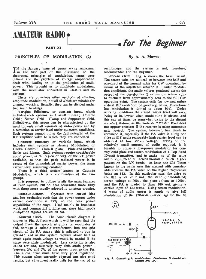
Volume XII! THE SHORT WAVE MAGAZINE 657
AMATEUR RADIO tI *for The Beginner
PART XI
PRINCIPLES OF MODULATION (2)
IN the January issue of SHORT WAVE MAGAZINE,in the first part of this discussion on the
theoretical principles of modulation, terms weredefined and the problem of voltage amplificationdealt with, leading on to the production of audiopower. This brought us to amplitude modulation,with the modulator connected in Class -B and itsvariants.
There are numerous other methods of effectingamplitude modulation, not all of which are suitable foramateur working. Broadly, they can be divided undertwo main headings:
Vari ble Efficiency, or constant input, whichincludes such systems as Class -B Linear ; ControlGrid ; Screen Grid ; Clamp and Suppressor Grid.Collectively, this group can be characterised by theneed for only small amounts of audio power and bya reduction in carrier level under quiescent conditions.Such systems cannot utilise the full potential of theRF amplifier valve to which they are connected.
Constant Efficiency or variable input, whichincludes such systems as Heising Modulation orChoke Control ; Class -B plate ; Plate -and -Screen ;Series and Linear. Such systems require considerableaudio power, in the region of 50% of the RF poweravailable, so that the peak radiated power is inexcess of the unmodulated carrier power, the meancarrier level remaining constant.
There is a third system known as CathodeModulation, which is a combination of the twogroups.
It is proposed to outline briefly the main featuresof each system, but to deal somewhat more fullywith those more usually adopted in amateur practice.
Class -B Linear. Operates with cut-off biasand low excitation such that the power output undercarrier conditions is 25% of the peak powercapabilities of the stage. Used mainly in broadcastwork and commercial installations, since high anodedissipation figures are called for.
Control Grid. The basic circuit diagram isshown in Fig. 5, from which it will be seen that theoutput from the speech amplifier or modulator isfed, through a suitable transformer, into the gridcircuit of the PA stage ; this is adjusted to run inClass -C, and in this system requires about half asmuch again anode voltage as would be needed if thestage were plate modulated. Less excitation is alsocalled for and, relatively, very little audio power-between 2% and 5% of the power input to the PA.The audio drive must have very good regulation.This system when correctly adjusted can give goodresults, but adjustment really calls for the use of an
By A. A. Mawse
oscilloscope, and the system is not, therefore,recommended for the beginner.
Screen Grid. Fig. 6 shows the basic circuit.The screen volts are reduced to between one-half andone-third of the normal value for CW operation, bymeans of the adjustable resistor R. Under modula-tion conditions, the audio voltage produced across theoutput of the transformer T causes the screen voltsto fluctuate from approximately zero to the full CWoperating point. The system calls for low and rathercritical RF excitation, of good regulation. Distortion -less modulation is limited to about 80%. Underworking conditions the actual carrier level will vary,being at its lowest when modulation is absent, andthis can at times be somewhat trying to the distantreceiving station, as the noise or " mush " level doesnot appear constant if the receiver is using automaticgain control. The system, however, has much tocommend it, especially if the PA valve is a big one(like an 813) and a reasonably high carrier level can beobtained at low screen voltage. Owing to therelatively small amount of audio required, it isfeasible to utilise a low -power modulator for con-ventional plate -and -screen modulation of a Top Band10 -watt transmitter, and to make use of the sameaudio equipment to screen -modulate much higherpowers on the DX bands. At least one Old Timerknown to the writer uses this method with consider-able success, the PA valve on the higher frequenciesbeing an 813. In this particular case, the drive tothe 813 is set at 2 mA, the static (unmodulated)screen voltage at 200v., the plate voltage at 1200v.,and the PA is loaded to draw 100 mA, giving acarrier input of 120 watts. Using screen modulation,6 watts of audio power is ample to give fullmodulation of the 120 -watt carrier, against the 60
RF Drivc¡
MOdulotor" output
RFC
_Grid has
RFC
RF. Out
CLASS- CAMPLIFIER
Fig. 5. Control grid modulation Condenser C should notexceed .002 F.F.
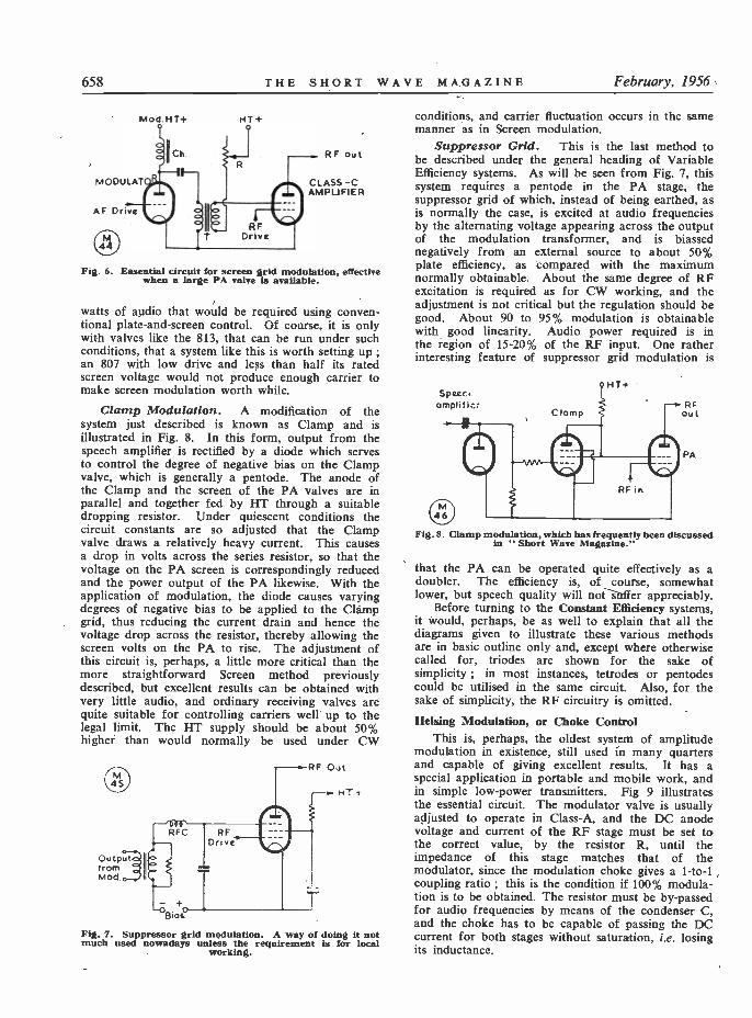
658 THE SHORT WAVE MAGAZINE February, 1956
HT+
44
RF out
CLASS -CAMPLIFIER
Fig. 6. Essential circuit for screen grid modulation, effectivewhen a large PA valve is available.
watts of audio that would be required using conven-tional plate -and -screen control. Of course, it is onlywith valves like the 813, that can be run under suchconditions, that a system like this is worth setting up ;an 807 with low drive and less than half its ratedscreen voltage would not produce enough carrier tomake screen modulation worth while.
Clamp Modulation. A modification of thesystem just described is known as Clamp and isillustrated in Fig. 8. In this form, output from thespeech amplifier is rectified by a diode which servesto control the degree of negative bias on the Clampvalve, which is generally a pentode. The anode ofthe Clamp and the screen of the PA valves are inparallel and together feddropping resistor. Under quiescent conditions thecircuit constants are so adjusted that the Clampvalve draws a relatively heavy current. This causesa drop in volts across the series resistor, so that thevoltage on the PA screen is correspondingly reducedand the power output of the PA likewise. With theapplication of modulation, the diode causes varyingdegrees of negative bias to be applied to the Clampgrid, thus reducing the current drain and hence thevoltage drop across the resistor, thereby allowing thescreen volts on the PA to rise. The adjustment ofthis circuit is, perhaps, a little more critical than themore straightforward Screen method previouslydescribed, but excellent results can be obtained withvery little audio, and ordinary receiving valves arequite suitable for controlling carriers well up to thelegal limit. The HT supply should be about 50%higher than would normally be used under CW
o-Outputf rom 1IMod.
RFC RFDrive
c
Bias
RF Out
HT -I
Fig. 7. Suppressor grid modulation. A way of doing it notmuch used nowadays unless the requirement is for local
working.
conditions, and carrier fluctuation occurs in the samemanner as in Screen modulation.
Suppressor Grid. This is the last method tobe described under the general heading of VariableEfficiency systems. As will be seen from Fig. 7, thissystem requires a pentode in the PA stage, thesuppressor grid of which, instead of being earthed, asis normally the case, is excited at audio frequenciesby the alternating voltage appearing across the outputof the modulation transformer, and is biassednegatively from an external source to about 50%plate efficiency, as compared with the maximumnormally obtainable. About the same degree of RFexcitation is required as for CW working, and theadjustment is not critical but the regulation should begood. About 90 to 95% modulation is obtainablewith good linearity. Audio power required is inthe region of 15-20% of the RF input. One ratherinteresting feature of suppressor grid modulation is
Space..omplific: RF
out
PA
Fig. 8. Clamp modulation, which has frequently been discussedin "Short Wave Magazine."
that the PA can be operated quite effectively as adoubler. The efficiency is, of course, somewhatlower, but speech quality will noter appreciably.
Before turning to the Constant Efficiency systems,it would, perhaps, be as well to explain that all thediagrams given to illustrate these various methodsare in basic outline only and, except where otherwisecalled for, triodes are shown for the sake ofsimplicity ; in most instances, tetrodes or pentodescould be utilised in the same circuit. Also, for thesake of simplicity, the RF circuitry is omitted.
Heising Modulation, or Choke ControlThis is, perhaps, the oldest system of amplitude
modulation in existence, still used in many quartersand capable of giving excellent results. It has aspecial application in portable and mobile work, andin simple low -power transmitters. Fig 9 illustratesthe essential circuit. The modulator valve is usuallyadjusted to operate in Class -A, and the DC anodevoltage and current of the RF stage must be set tothe correct value, by the resistor R, until theimpedance of this stage matches that of themodulator, since the modulation choke gives a 1 -to -1coupling ratio ; this is the condition if 100% modula-tion is to be obtained. The resistor must be by-passedfor audio frequencies by means of the condenser C,and the choke has to be capable of passing the DCcurrent for both stages without saturation, i.e. losingits inductance.
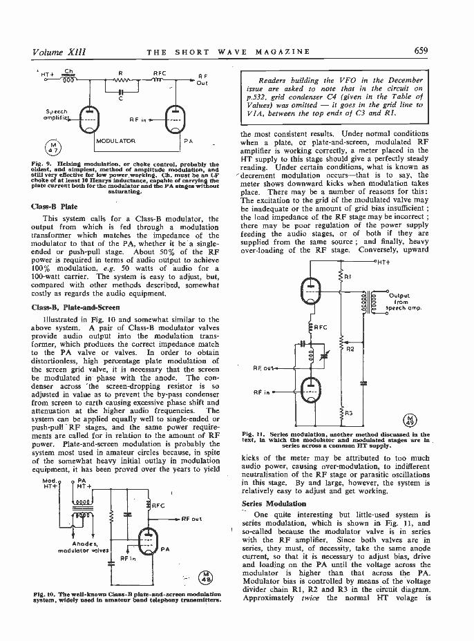
Volume XIII THE SHORT WAVE MAGAZINE 659
RFC
SNeechomplifi
RFOu t
Fig. 9. HeIsing modulation, or choke control, probably theoldest, and simplest, method of amplitude modulation, andstill very effective for low power working. Ch. must be an LFchoke of at least 10 Henrys inductance, capable of carrying theplate current both for the modulator and the PA stages without
saturating.
Class -B Plate
This system calls for a Class -B modulator, theoutput from which is fed through a modulationtransformer which matches the impedance of themodulator to that of the PA, whether it be a single -ended or push-pull stage. About 50% of the RFpower is required in terms of audio output to achieve100% modulation, e.g. 50 watts of audio for a100 -watt carrier. The system is easy to adjust, but,compared with other methods described, somewhatcostly as regards the audio equipment.
Class -B, Plate -and -Screen
Illustrated in Fig. 10 and somewhat similar to theabove system. A pair of Class -B modulator valvesprovide audio output into the modulation trans-former, which produces the correct impedance matchto the PA valve or valves. In order to obtaindistortionless, high percentage plate modulation ofthe screen grid valve, it is necessary that the screenbe modulated in phase with the anode. The con-denser across the screen -dropping resistor is soadjusted in value as to prevent the by-pass condenserfrom screen to earth causing excessive phase shift andattenuation at the higher audio frequencies. Thesystem can be applied equally well to single -ended orpush-pull RF stages, and the same power require-ments are called for in relation to the amount of RFpower. Plate -and -screen modulation is probably thesystem most used in amateur circles because, in spiteof the somewhat heavy initial outlay in modulation
it has been proved over the years to yieldMod.PAHT+I HT+
Anodes,modulotor volves
RFC
PA
RE out
Fig. 10. The well-known Class -B plate -and -screen modulationsystem, widely used in amateur band telephony transmitters.
Readers building the VFO in the Decemberissue are asked to note that in the circuit onp.532, grid condenser C4 (given in the Table ofValues) was omitted - it goes in the grid line toVIA, between the top ends of C3 and RI.
the most consistent results. Under normal conditionswhen a plate, or plate -and -screen, modulated RFamplifier is working correctly, a meter placed in theFIT supply to this stage should give a perfectly steadyreading. Under certain conditions, what is known asdecrement modulation occurs-that is to say, themeter shows downward kicks when modulation takesplace. There may be a number of reasons for this:The excitation to the grid Of the modulated valve maybe inadequate or the amount of grid bias insufficient ;the load impedance of the RF stage may be incorrect ;there may be poor regulation of the power supplyfeeding the audio stages, or of both if they aresupplied from the same source ; and finally, heavyover -loading of the RF stage. Conversely, upward
HT+
Outputfrom
speech amp.
RE out
RF in
Fig. 11. Series modulation, another method discussed in thetext, in which the modulator and modulated stages are in
series across a common HT supply.
kicks of the meter may be attributed to too muchaudio power, causing over -modulation, to indifferentneutralisation of the RF stage or parasitic oscillationsin this stage. By and large, however, the system isrelatively easy to adjust and get working.
Series ModulationOne quite interesting but little -used system is
series modulation, which is shown in. Fig. 11, andso-called because the modulator valve is in serieswith the RF amplifier. Since both valves are inseries, they must, of necessity, take the same anodecurrent, so that it is necessary to adjust bias, driveand loading on the PA until the voltage across themodulator is higher than that across the PA.Modulator bias is controlled by means of the voltagedivider chain Rl, R2 and R3 in the circuit diagram.Approximately twice the normal HT volage is
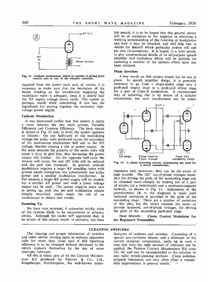
660 THE SHORT WAVE MAGAZINE February, 1956
RFIn
RF C.c
Mod output
Fig. 12. Cathode modulation, which is capable of giving goodresults and is one of the simpler systems.
required from the power pack and, of course, it isnecessary to make sure that the insulation of theheater winding on the transformer supplying themodulator valve is adequate, since it is nearly halfthe HT supply voltage above earth. The system is,perhaps, worth while considering if one has theingredients for putting together the necessary high -voltage power supply.
Cathode ModulationIt was mentioned earlier that this system is really
a cross between the two main groups, VariableEfficiency and Constant Efficiency. The basic circuitis shown in Fig. 12 and, in brief, the system operatesas follows: On one half -cycle of the modulatingvoltage the audio volts produced across the secondaryof the modulation transformer will add to the HTvoltage, thereby causing a rise in power output. Atthe same moment the polarity of the audio volts willcause a drop in grid bias, thus increasing the poweroutput still further. On the opposite half -cycle thereverse will occur, the nett HT volts will be reducedand the grid bias increased. In general, cathodemodulation requires a larger RF amplifier valve withgreater anode dissipation, but substantially less audiopower and a smaller modulation transformer. Inlike manner, a larger RF power supply will be needed,but a smaller AF power unit with a lower voltageoutput can be used. The system requires some carein setting up, and, like the grid modulation systemalready described, really needs the aid of anoscilloscope to obtain best results.
Summing UpWe have now reviewed, if somewhat briefly, most
of the systems likely to be encountered in amateurcircles. Although the reader will appreciate that, inan article of this nature, much. if necessity, has been
left unsaid, it is to be hoped that this general surveywill be of assistance to the beginner in obtaining aworking understanding of the meaning of modulationand how it may be obtained, and will help him todecide for himself which particular system will suithis own circumstances. It is hoped, in a later article.to give constructional details of an all-purpose speechamplifier and modulator which will be suitable foroperating a number of the systems which have justbeen outlined.
Phase InvertersA few words on this subject would not be out of
place. In speech amplifier design, it is generallynecessary to go from a single -ended stage into apush-pull output stage or a push-pull driver stagefor a pair of Class -B modulators. A conventionalway of achieving this is by means of a suitabletransformer, but such transformers can be rather
Phase Invertor Push -Pull(Twin triode) succeeding stage
Fig. 13. A phase inverting circuit, eliminating the need fora driver transformer.
expensive and, moreover, they can be the cause ofhum trouble. The 180° out -of -phase voltages neces-sary for driving the grids of the succeeding stage canbe obtained more cheaply by making use of a pairof triodes (or a twin -triode) and a resistance -capacitynetwork, as shown in Fig. 13. Adjustment of thepotentiometer (R in the diagram) is made untilbalanced excitation is provided at the grids of thesucceeding stage. There are a number of variationsof this idea, but the object remains the same-toprovide balanced, out -of -phase voltages, for drivingthe grids of the succeeding push-pull stage.
Next Month: Choke Control Modulator forthe Beginner's Transmitter.
CLEANINGThe cleaning and proper lubrication of switches
and other similar moving parts in radionic apparatuscalls for more than usual care if full operatingefficiency is to be obtained without detriment to theswitch contacts themselves by the use of someimproper lubricant.
All this is taken care of by the Contact Mainten-ance Kit produced by Painton & Co., Ltd.,Kingsthorpe, Northampton, the well-known manu-
SWITCHESfacturers of resistors and switches. Consisting of aspecial non -corrosive cleaner and a lubricant of thecorrect chemical composition, made up in such away that only the right amount of lubricant can beapplied, the Painton Contact Maintenance Kit costs1 ls. 6d. and can be recommended as the solution toany radio switch -cleaning problem. Clean switches,properly lubricated, can very often effect a remark-able improvement in general results.
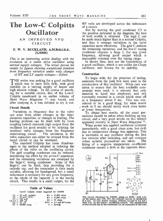
Volume XIII THE SHORT WAVE MAGAZINE 661
The Low -C ColpittsOscillator
AN IMPROVED VFOCIRCUIT
F. W. V. BUCKLAND, A.M.Brit.I.R.E.(G3DIR)
This is an interesting article dealing with theevolution of a stable drive oscillator usingnormal supply voltages. The writer proves hisresults by figures showing exceptional freedomfrom frequency variation under wide changes
of HT and LT supply voltages. Editor.
EIE writer was seeking for a good oscillator1 which was to have little drift, with good
stability on a varying supply of heater andhigh tension voltage. In the course of search-ing for a suitable circuit, that of the Low -CColpitts mentioned in an earlier volume ofShort Wave Magazine (1) was found, andafter studying it, it was decided to try it out.Circuit Details
Variations in frequency due to the valvecan arise from either changes in the inter -electrode capacities, or changes in loading. Theloading problem can be dealt with by loosecoupling (which demands high output from theoscillator for good results) or by isolating theresultant valve changes from the frequencydetermining circuit. The variations in thevalve capacities can either be isolated from thetuned circuit or can be swamped.
The standard Colpitts has some disadvan-tages in the method adopted in reducing theeffects of the valve on the oscillating circuit.The grid coupling condenser can be reduced,minimising the effect by the series -C argument,and the remaining variations are swamped bythe large -C tuning condenser. Some of thislarge -C can be fixed, thus providing for acathode tap, and the remainder is then madevariable, allowing for bandspread, but a smallinductance is necessary for any given frequency,as the whole of the capacity is in the tuningcircuit. This results in a small output, for the
Table ofLow -C Colpitts circuit
Cl = 30 µµF, variableC2 = 30 µµF, NTC.C3 = 100 µµF
C4, C5 = .001 µFC6 .01 µFRI = 10,000 ohms
Valuessuggested by G3DIR
R2 = 15,000 ohmsR3 = 33,000 ohmsR4 = 50 ohms
RFC = 2.5 mH RF chokeV = EF50]
RF volts are developed across the inductanceof a circuit.
But by moving the grid condenser C3 tothe position indicated in the diagram, the bestof both worlds is obtained. The high C canbe made much higher than in a normal Colpitts,and thus it swamps variations in the valvecapacities more effectively. The grid C reducesthe remaining variations, and the low -C tuningcondenser requires a large L for any givenfrequency, allowing good output which isreasonably constant over the tuning range.
In theory then, here are the foundations ofa good oscillator, which is not unlike the Clapposcillator, well known for its stability.
ConstructionTo begin with, for the purposes of testing,
materials from the junk box were used in theconstruction of this oscillator. While care wastaken to ensure that the best available com-ponents were used, it is stressed that onlymaterial to hand was employed, and thiseventually resulted in a circuit which went offat a frequency about 9 mc. This was con-sidered to be a good thing, for what wouldwork at 9 mc should surely work even betterat lower frequencies.
To obtain best results, all the usual pre-cautions should be taken when building up anycircuit, and a very good article on this subjectappeared recently in Short Wave Magazine (2).
When power was applied oscillation occurredimmediately, with a good clean note, but driftdue to temperature change was apparent. Thisis inevitable in any oscillator during the firstfew minutes after switching, and can continueunless suitable precautions are taken. Thefitting of a negative temperature co -efficientcondenser caused a drift in the opposite direc-
R2
C3
HT Rodn5v225v275v300v
3.5 vq 51.-04 0
5.0 v6.Ov6.3v9 o\
0C6 a o 0 91
092 0 0
h hEF50
The circuit discussed by G3DIR, using an EF50 ; with 6.3v.on the heater and 175v. HT, the cathode current in oscillationis 6 mA. At 3.5v. heater voltage, cathode current is 4.5 mA ;with 3.2v. on the heater, oscillation ceased. The significanceof this circuit Hes in the condenser C3, as explained in the text.
662 THE SHORT WAVE MAGAZINE February, 1956
TABLE 1
Oscillator Frequency 9 mc approximately
Change in HT Volta Change in Frequency
175v. to 225v.
225v. to 275v.
275v. to 300v.
70 cycles.
80 cycles.
30 cycles.
tion, so it is apparent that such drift can beeliminated by choice of a suitable condenser.Each oscillator will require its own individualtreatment with NTC condensers, and in thiscase, having made a reasonable adjustment,the matter was not pursued further, as finaladjustment would be made in the productionmodel-should the circuit prove satisfactory.So the circuit was allowed to warm up andbecome reasonably stable before carrying outthe tests which follow.
Testing
Signals from the oscillator were picked upon a CR -100 receiver, and a beat note obtainedby injecting simultaneously the signal from acrystal oscillator operating on about 9 mc. Itwas found that the output from the variableoscillator was enough to require the RF gaincontrol of the receiver to be backed off, thuseliminating outside interference, and the audiooutput was sufficient for testing with the AFgain control almost at minimum. A checkshowed that the output was reasonably constantover the tuning range, which incidentally, inthe circuit as shown, was from about 7 mcto just over 9 mc.
The changes in frequency were measured bybeating the resultant from the variable and thecrystal oscillators with an audio oscillator.
As the oscillator was to operate from anunstabilised supply the first check was to deter-mine the frequency change due to changes inHT voltage. The supply in use was capableof being switched in steps which gave 175v.,225v., 275v. and 300v. The oscillator wasrunning on the 175v. tap, and when this wasswitched to the 225v. position there was re-markably little change in frequency. This ledto the other voltages being applied in turn,and the results are given in Table 1.
The next check was to be variations in fre-quency due to changes in the heater supplyvoltage. Such variations are a source offrequency change which are seldom dealt withbut which, nevertheless, are a cause of con-siderable trouble. It was found that the EF50
valve oscillated quite well with only 3.5v. ontha heater, but it ceased to function when theheater supply was reduced to 3.2v. The 3.5v.position was the one used as the minimumin the tests. The oscillator was run at thelower voltage, and when steady, the heatersupply was quickly increased to 6v., and thefrequency change measured when it hadbecome steady again. The results, tabulated inTable 2, show that the oscillator is quite stable,and that normal heater voltage variationsshould have little or no effect.
The larger change in frequency when in-creasing from 4v. to 6v. was investigated, andit was found that as the voltage was raisedgradually from 3.5v., so the frequency movedfirst in one direction, and then swung to theother direction. It was at a maximum in thefirst direction when the heater voltage wasabout 4v., and this accounts for the largerchange obtained, and shown in the Table.When increased to 6v. from voltages above
TABLE 2
Oscillator Frequency 9 mc approximately
Change in Heater Volts Change in Frequency
3.5v. to 6v.
4.0v. to 6v.
5.0v. to 6v.
120 cycles.
200 cycles.
85 cycles.
4v. the frequency change was always in thesame direction.
The loading by a subsequent circuit was notchecked, as it did not enter into the particularproblem involved, but it would seem that ifthe output was taken from the anode of thevalve the loading circuit would be sufficientlyisolated from the tuned circuit as to cause littletrouble. The grid coupling condenser mightbe reduced from the 100 µµF fitted to providefurther isolation, if it were felt to be necessary.
The results obtained detailed above were sosurprising that they were repeated the follow-ing day in the presence of an independentobserver, and similar figures were obtained.These figures are given as they were taken,and a full check was made to ensure that therewas no mistake.
REFERENCES
" Improving the Colpitts," Williams.'2) " Approach to VFO Design," Walker.
Short Wave Magazine, April, 1955 ;December, 1955.

Volume X111 THE SHORT WAVE MAGAZINE 663
There is no doubt that by connecting thegrid coupling condenser adjacent to the tuningcircuit, and the large swamping condenserremote from this circuit, an oscillator can beproduced which although nominally a Colpitts,is a considerable improvement on the normalmethod of connection. The series -tuned ver-sion, popular for a long time now as the Clapp,
is also an improvement on the original Colpittsdesign, but suffers from a falling outputtowards one end of the tuning range. Thisparallel tuned version appears to have over-come this latter disadvantage, and is therefore,providing the stabilities are at least equal, abetter oscillator. Should it be used for a VFOit is suggested that a later stage be keyed.
THEOTHERMAN'SSTATION
G3DG N
ANOTHER photograph of the station of G3DGN-owned and operated by G. I. Turner, Deegeen,
Clifford Road, New Barnet, Herts. - appeared onp.247 of the July issue Of SHORT WAVE MAGAZINE. Apoint of particular interest about G3DGN is that thestation is' accommodated in the living space of afive -room caravan on a semi -permanent site. It isalso the twelfth installation under the call since theG licence was issued-for G3DGN actually startedin Ceylon as VS7IT in 1946. From VS7, 98 countrieswere worked during eight months' activity on the7, 14 and 28 me bands, with a total of 1,100 contacts,using 300 watts on phone and 700w. CW. VS7ITthat -was returned to England in late '47, and thepresent licence was issued in February 1948.
G3DGN is an all-round station, operated on CWand phone on most bands, with a general interest ineverything that goes on, as well as in QSO'ing for itsown sake. A compact filing system is maintained tokeep track of contacts, which by now total some1,500 different stations worked. The main receiveris the well-known ex -Service type R.107, with aseparate transmitter for One -Sixty ; the No. 2 set isfor the HF bands and runs a pair of 807's at 110watts. A third transmitter is for two metres, with an829 in the PA. The BC -221 frequency meter is usednot only for its intended purpose, but also, on occa-sions, as a VFO. Other equipment includes an Avo,a megger and what G3DGN describes as ` a set ofwavemeters." However, he finds one of the most
useful items in the test equipment category to be aneon tube mounted on a jack -plug!
Because the whole G3DGN family is interested inthe station and G3DGN-jr. is not yet three, safetyprecautions are stringent ; a foot switch within easyreach cuts mains power to everything, and a leakagetrip likewise switches off the mains if more than afew mA pass between the live side and earth on theAC supply. No HT points are exposed, and allunits are boxed and earthed.
That G3DGN himself is a man of parts isinstanced by the fact that not only is he keen on allaspects of Amateur Radio, including Club activities,but he is also interested in sailing and-cooking!Dexterity with the fry -pan must be a great help (oris it!) to his XYL, who herself takes a keen interestin the operation of the station. A happy family intheir hide-out in Hadley Woods.
664 THE SHORT WAVE MAGAZINE February, 1956
NEW QTITsG2HGT, W. T. Black, 9 Nursery
Street, Tottenham, London,N.17.
G3AFN, W. E. Brown, 53 St.Winifred's Road, Teddington,Middlesex.
GI3EYQ, A. E. Donegan, 67Antrim Street, Lisburn, Co.Antrim.
GM3HZA, R. M. Corcoran, 37Kilmacolm Road, Greenock,Renfrewshire.
G3KKF, J. Court, 85 ClarendonStreet, Dover, Kent.
G3KNW, J. S. Watt, 30 TattenhoeLane, Bletchley, Bucks.
G3KPJ, A. W. Butcher, RectoryCottage, West Hanningfield, nr.Chelmsford, Essex.
G3KPS, F. A. Smith, 5 ShelleyAvenue, Boldon Colliery, Co.Durham.
G3KQH, J. R. Hunt, 47 HillStreet, Wellingborough,Northants.
G3KQQ, C. A. Mattacks, 307Compton Buildings, GoswellRoad, London, E.C.1.
G3KRC, K. R. Clarke, 24 GalleyLane, Barnet, Herts.
G3KRL, J. Schofield, 21 PrincessStreet, Batley, Yorkshire.
G3KRP, E. G. Powell, 169Dominion Road, Glenfield,Leicester.
G3KSL, D. G. Quarrington, 69Pennant Road, Rochester, Kent.
GW3KSQ, C. T. Jay, 40 AbbotsClose, Margam, Port Talbot,Glam.
G3KTI, M. V. Rees, 4 ValleyRoad, Lydney, Glos.
CHANGE OF ADDRESS
G2AOZ, G. W. F. Ashford, 18Gipsy Lane, Attleborough,Nuneaton, Warks.
G2DNY, C. A. Wheaton, No. 2
This space is available for the pabliatiea of the addresses of al MMusof sew U.B. alkipu, as lead, or changes of address of transmitteralready Beard. Al addresses published here are repriatd is thequarterly issue of the RADIO AMATEUR CALL EOOK "preparation. QTH's are inserted as they are received, up to the limitof the space auowºace each month. Please write dearly and address
oa a separate slip to QTH Section.
Police House, Whitchurch Road,Tavistock, Devon.
G2DQ, H. G. Collin, TudorHouse, Penny Royal Road,Danbury Common, Chelmsford,Essex.
G2KB, L. L Sidwell, 53 KingEdward's Road, Ware, Herts.
G3ABA, L. J. Kennard, c/o 14Norfolk Road, Thornton Heath,Surrey.
G3AIM, L. S. Wright, 29 LovelRoad, Speke, Liverpool, 19.
G3ANJ, A. J. Wall, 161 MonyhullHall Road, Kings Norton,Birmingham, 30. (Tel.: KingsNorton 3629).
G3APL, J. Russon, 59 RidgeRoad, Kingswinford, BrierleyHill, Staffs.
G3CEB, P. M. Scadden, c/o J.Holt & Co., Lagos, Nigeria.
G3CVG, S. Jackson, 22 BrookRoad, Morecambe, W.E., Lancs.(Tel.: Morecambe 1189).
G3DQO, A. L. Cawley, 6 NewtonRoad, Urmston, nr. Manchester,Lancs.
G3DXJ, T. Holbert (ex-VS6CQ).52b M.S.Q., Arborfield, Berks.
G3DZX, F. C. Bailey, 360Ridgacre Road,' Quinton, Birm-ingham, 32. (Tel.: Wood gate2011).
G3EKJ, H. F. Mattacks, 43 Pren-dergast Road, Blackheath,London, S.E.3.
G3EPV, R. D. Emes, 142 SussexRoad, Harrow, Middlesex.
G3FIQ, A. W. H. Cox, 17 Ken-sington Church Street, Kensing-ton, London, W.8. (Tel.:WEStern 1994).
GI3GQA, W. P. Hewitt, 36 SicilyPark, Finaghy, Belfast.
G3GVV, R. J. Hughes, 24 Camp -den Road, Tuffley, Gloucester.
G3HZP, H. D. James, 77 Fleet-wood Road, Dollis Hill,London, N.W.10.
G3IAZ, A. H. Wickham, 18Carmel Gardens, Darlington,Co. Durham.
G3IKN, Cpl. Stagg, V. A., 59A.M.Q., R.A.F. Station, Mar -ham, Kings Lynn, Norfolk.
G3INU, R. J. Appleby, 91Tewkesbury Road, Clacton -on -Sea, Essex.
GW3ISJ, J. J. Caulfield; 34 Green -meadow Drive, Tongwynlais,Cardiff, Glam.
G3IZ, C. H. Thorpe, 40 BellarsLane, Malvern, Worcs.
G3JBL, G. A. Millray, 6 DurhamAvenue, Scotforth, Lancaster.
G3JED, G. A. Cunningham, 17Meads Cottages, Mansion Lane,Iver, Bucks.
G3JFN, C. Sonley, 5 St. NicholasGardens, Hessle High Road,Hull, Yorkshire. (Tel.: Central55748).
G3JQG, T. Scatter, B.E.M., 122Birch Road, Ambrosden,Bicester, Oxon.
G3KAW, J. W. Maddison, 23Mayfield Avenue, Dover, Kent.
GM4HR, S. Ramsay, 5 BaluniePlace, Douglas and Angus,Dundee, Angus.
CORRECTION
G3CWZ, D. R. Layzell, Sunning -dale, Cann, Shaftesbury, Dorset.(Tel.: Shaftesbury 2164).
GM3HGU, D. Melville, c/oAnderson, 48 Sythrum Crescent,Glenrothes, Fife.
G3KLM, P. J. Le Moine, TheCrab and Lobster Inn, MillHamlet, Sidlesham, Chichester,Sussex.

Volume XIII THE SHORT WAVE MAGAZINE 665
THE MONTH WITH THE CLUBSBy"Club Secretary "
(Dead -line for March Issue : FEBRUARY 17)
BACK to work, and into the 1956 season ! MCCig over, the Christmas break is past us, New Year
celebrations dead and gone, and there's nothing forit but to get along with some good solid work onbehalf of the Club. Apart from the winter routine oflectures and discussions, it isn't too early to think ofthe renovations necessary in the Clubroom, or eventhe overhaul of the aerial system - or even thebuilding of that mobile for the summer, which isnever quite so far away as you think it is.
Successful Christmas Parties are reported by manyClubs-mostly the larger ones, for it seems that thesocial angle varies in direct ratio to the size of theClub.
Cardiff report a fair number of new faces, mostof them wishing to take the RAE, and a Morse classis being formed to help in this direction. OnFebruary 13 GW3HJR will " ramble " on How toMake and Do, Some Fiddles, and Hints and Kinks.This will take place at the British Volunteer, TheHayes, Cardiff. On March 12 there will be a lectureon Electronics by Mr. J. J. Richardson.
Clifton had no less than 17 stations in theirChristmas morning Club Net on the Top Band. OnFebruary 3 and 17 they hold Constructional Eveningsand Ragchews ; on the 10th a Quiz ; and on the24th a Junk Sale. Meetings every Friday, 7.30 p.m.at 225 New Cross Road, London,S.E.I4.
Coventry are to hear G5GR onAerials and Switches on February13 ; they have a Junk Sale onthe 27th, and due warning is alsogiven of their Annual Dinner, atthe Barras House Hotel, onApril 7.
Lothians are to have a talk byMr. W. T. Bell of the GPOEngineering Department on Feb-ruary 9. The subject-Radio andTelevision Interference and theRadio Amateur ! On February 23they will hear a talk on PoliceRadio by Chief Inspector Bruce.All very official ! Meetings are at25 Charlotte Square, Edinburgh.7.30 p.m.
Midland heard a talk, onJanuary 24, on " A Ham on theSiam Railroad," by G3BA.Wellingborough held their AGMon January 5, and the Secretaryannounced the Club call-sign-G3KSX. Meetings are held every
Thursday at the Co-operative Offices, Silver Street,and a full programme up to the end of April hasbeen arranged.
Ripley (Derby) report for the first time. Theywere formed last September and already have over40 members. During the past three months theyhave held lectures, demonstrations and film shows,and it was hoped to enter for MCC, until accommo-dation difficulties " put paid " to this. An aerialdemonstration and a Hi -Fi demonstration are plannedfor the future. Meetings take place at Shirley RoadSchools, Ripley, every Tuesday at 7 p.m.
Slade announce the following events : February 3,Talk by G3BA ; February 17, Junk Sale ; March 2,Talk on Rectifiers (Standard Telephones and Cables) ;March 16, Talk on Electronic Musical Instruments.
South Manchester will be hearing a lecture onRadar and its Applications on February 10, and theyhold a Hot -Pot Supper on February 17. The latterwill take place at the Wellington Hotel, Manchester,and reservations may be made at 5s. 6d. The RAECourse is well under way on Monday evenings at8 p.m., in the Club HQ at Ladybarn House, 17
Mauldeth Road, Manchester 20.Surrey (Croydon) held their Annual Dinner on
January 27 at the Greyhound, when, no doubt, a
Presentation of the " G2AK Silver Jubilee Shield " to G3JEF and G3HKC by thepresident, Mr. W. E. Chilvers, at the Slade Radio Society's annual dinner recently.
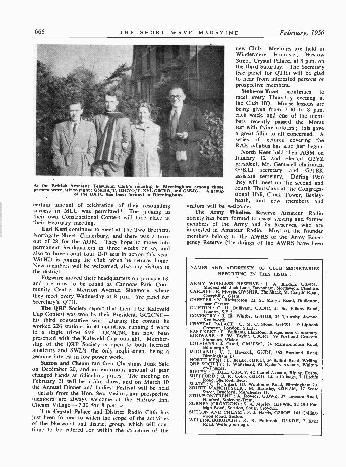
666 THE SHORT WAVE MAGAZINE February, 1956
At the British Amateur Television Club's meeting in Birmingham among thosepresent were, left to right : G3KBA/T, G3CVO/T, XYL G3CVO, and G3EJO. A group
of the BATC has been formed in Birmingham.
certain amount of celebration of their resoundingsuccess in MCC was permitted ! The judging intheir own Constructional Contest will take place attheir February meeting.
East Kent continues to meet at The Two Brothers,Northgate Street, Canterbury, and there was a turn-out of 28 for the AGM. They hope to move intopermanent headquarters in three weeks or so, andalso to have about four D -F sets in action this year.VS1HD is joining the Club when he returns home.New members will be welcomed, also any visitors inthe district.
Edgware moved their headquarters on January 18,and are now to be found at Cannons Park Com-munity Centre, Merrion Avenue, Stanmore, wherethey meet every Wednesday at 8 p.m. See panel forSecretary's QTH.
The QRP Society report that their 1955 KaleveldCup Contest was won by their President, GC2CNC-his third consecutive win. During the contest heworked 226 stations in 40 countries, running 5 wattsto a single tri-tet 6V6. GC2CNC has now beenpresented with the Kaleveld Cup outright. Member-ship of the QRP Society is open to both licensedamateurs and SWL's, the only requirement being agenuine interest in low -power work.
Sutton and Cheam ran their Christmas Junk Saleon December 20, and an enormous amount of gearchanged hands at ridiculous prices. The meeting onFebruary 21 will be a film show, and on March 10the Annual Dinner and Ladies' Festival will be held-details from the Hon. Sec. Visitors and prospectivemembers are always welcome at the Harrow Inn.Cheam Village - 7.30 for 8 p.m.
The Crystal Palace and District Radio Club hasjust been formed to widen the scope of the activitiesof the Norwood and district group, which will con-tinue to be catered for within the structure of the
new Club. Meetings are held inWindermere House, WestowStreet, Crystal Palace, at 8 p.m. onthe third Saturday. The Secretary(see panel for QTH) will be gladto hear from interested persons orprospective members.
Stoke-on-Trent continues tomeet every Thursday evening atthe Club HQ. Morse lessons arebeing given from 7.30 to 8 p.m.each week, and one of the mem-bers recently passed the Morsetest with flying colours ; this gavea great fillip to all concerned. Aseries of lectures covering theRAE syllabus has also just begun.
North Kent held their AGM onJanuary 12 and elected G2YZpresident, Mr. Gemmell chairman,G3KLI secretary and G3JBKassistant secretary. During 1956they will meet on the second andfourth Thursdays at the Congrega-tional Hall, Clock Tower, Bexley -heath, and new members and
visitors will be welcome.The Army Wireless Reserve Amateur Radio
Society has been formed to assist serving and formermembers of the Army and its Reserves, who areinterested in Amateur Radio. Most of the foundermembers belong to the AWRS of the Army Emer-gency Reserve (the doings of the AWRS have been
NAMES AND ADDRESSES OF CLUB SECRETARIESREPORTING IN THIS ISSUE :
ARMY WIRELESS RESERVE : J. A. Bladon, G3FDU,Madresfield, Jack Lane, Davenham, Northwich, Cheshire.
CARDIFF : R. Morris, GW3HJR, The Shack, St. Cenydd Road,Caerphilly, Glam.
CHESTER : N. Richardson, 23, St. Mary's Road, Dodleston,near Chester.
CLIFTON : C. H. Bullivant, G3DIC, 25 St. Fillans Road,London, S.E.6.
COVENTRY : J. H. Whitby, G3HDB, 24 Thomby Avenue,Kenilworth.
CRYSTAL PALACE : G. M. C. Stone, G3FZL, 10 LiphookCrescent, London, S.E.23.
EAST KENT : D. Williams, Llandogo, Bridge, near Canterbury.EDGWARE : E. W. Taylor, G3GRT, 99 Portland Crescent,
Stanmore, Middx.LOTHIANS : J. Good, GM3EWL, 24 Mansionhouse Road,
Edinburgh 9.MIDLAND : C. J. Haycock, G3JDJ, 360 Portland Road,
Birmingham 17.NORTH KENT : F. Beadle, G3KLI, 56 Balliol Road, Welling.QRP SOCIETY: J. Whitehead, 92 Ryden's Avenue, Walton -
on -Thames.RIPLEY : T. Darn, G3FGY, 42 Laurel Avenue, Ripley, Derby.SHEFFORD : G. R. Cobb, G3IKG, Lilac Cottage, 7 Hitchin
Road, Shefford, Beds.SLADE : C. N. Smart, 110 Woolmore Road, Birmingham 23.SOUTH MANCHESTER : M. Barnsley, G3HZM, 17 Score
Street, Bradford, Manchester 11.STOKE-ON-TRENT : A. Rowley, G3JWZ, 37 Leveson Road,
Hanford, Stoke-on-Trent.SURREY (CROYDON) : S. A. Morley, G3FWR, 22 Old Far-
leigh Road, Selsdon, South Croydon.SUTTON AND CHEAM : F. J. Harris, G2BOF, 143 Colling-
wood Road, Sutton.WELLINGBOROUGH : K. R. Fulbrook, G3KRF, 2 Kent
Road, Wellingborough.

Volume XIII THE SHORT WAVE MAGAZINE 667
reported in previous issues), but membership is opento any serving or past member of AWRS ; anyserving or past member of any other Royal Signalsunit ; or any serving member of any non -Signalsunit. Club activities will be entirely non-military incharacter, and a programme is being drawn up forthe coming year. Full details from the Chairman,G8PG, or the Secretary, G3FDU (see panel forQTH).
Shefford meet each Friday at Digswell House,their Hq., and cover all electronic and allied subjects ;
Club reports are welcome for this feature, andshould be addressed to " Club Secretary," ShortWave Magazine, 55 Victoria Street, London,S.W.1, to arrive by February 17 latest for thenext issue.
the amateur call is G3FJE, and refreshments areavailable on the premises. The next meetings are onFebruary 17 (Technical lecture) and 24 (Film show).
NUTS ON DX"QSL THROUGH BOX 88"
SOME years ago it was the custom for a gentlemanwith the improbable but nevertheless genuine
name of Arabackle Oblifork to make spasmodicincursions into the columns of " DX Commentary."Like everyone else, we were highly sceptical abouthis authenticity, but we identified him as thecomposer of an extremely obscure piece of musicwhich actually appeared in print-just a week beforethe publishers went out of business.
All communication ceased abruptly until thearrival of a recent letter which, presumably, isintended to put us in the picture (as they laughinglydescribe it) ; though what the picture is, we still donot know. Suffice it to say that the voice ofhas been heard again, telling an even more incrediblestory than we should have expected from him.
It seems that he was unable to qualify for atransmitting licence for many years, for the reasonthat no one would believe that he was a Britishcitizen, once they had deciphered his signature andfound that his name really was what it looked like.In fact, the general tendency was to disbelieve in hisexistence altogether, and the G.P.O. rightly pointedout that the granting of a licence to a myth wouldset an awkward precedent. However, he seemed tohave a friend (since departed) at the Foreign Officeor some other august institution, and eventuallythings were sorted out. Arabackle was no fool-hepassed the Morse test and the Examination withoutthe slightest trouble, once the examiners had beenrevived after deciphering his signature.
Then, trading on the initial doubts as to hisnationality, he prevailed upon the authorities to givehim a distinctive call -sign ; in fact, he demanded nofewer than three of them-one for mobile, one forfixed, and the other for some experiments that heclaimed would enable him to radiate in the fourthdimension. Such was his pull in high places that hewas actually allocated the three calls GB2BA,GB4BA and GB6BA (hence the title of this article).
All would have been well had he not fallen amongpolitical fanatics. He always chose peculiar company,but these friends of his own choosing simply brain-washed him, and he emerged badly shrivelled, slightlycross-eyed, and convinced that he could not use theprefix GB, or even G, because he was firmlyindoctrinated with the guilty feeling that even to
think the word " Great " in connection with hismother -country was immoral. He was willing,however, to settle for the United Kingdom, and sohe changed his prefix, without warning or permission,and signed himself as UK2BA, UK4BA and UK6BA.
Arabackle's chief object in life was to show upall these holders of a mere eighty or ninety certificatesas cissies, and you can imagine his delight at thegreatly increased turnover of DX that resulted fromhis unauthorised change of prefix. His undoing washis own ridiculous sense of independence (or, as hepreferred to call it, his " apartness "), which forbadehim either to give his QTH or to have his callspublished in any book. Further, he looked on QSLBureaux as ridiculous manifestations of officialdomfor pandering to the herd. He therefore can onlyhave had himself to blame for the fact that all hisDX cards eventually found their way to Box 88,Moscow, leading to a nation-wideUzbek, Azerbaijan and Kazakhistan) for a highlyillegal transmitter.
The non -arrival of his cards thwarted his trophy -hunting obsession, and it seemed that the only logicalway (to hitn) of righting matters was to embark on apersonal search for them. His characteristicallythorough study of the Russian language cost himnearly three years off the air, and by the time he felthe was competent enough to set out on the GreatAdventure another fifty-six certificates had beenannounced. So he set to again, working AllBrazilian YL's, All Costa Rican Peanut Sellers, AllSiamese Trapeze Artists and most of the other awardswith which our readers are already doubtless familiar.(He nearly came to grief trying to acquire AllPsychiatrists in London, W.1, but when he adoptedthe technique of saying " My sigs are RST 599-howare yours? " they recognised a kindred spirit andobliged.)
The delay was most regrettable, however, becauseat the time of writing he had only just made arrange-ments to depart (through the usual channels) in searchof Box 88. He is confident of success, since, as hesays with no assumption of false modesty, " If Box 88has all my cards in it, it's a Pretty Big Box andshould be easy enough to locate."
We hope to hear more from him in due course,but readers might care to note that the business ofcalling at 55 Victoria Street and asking for Mr.Oblifork has been a little overdone. The one-timetypist who said, without blinking, that he didn'tusually come in on Tuesdays is now happily marriedand living in a detached villa in Surrey. L.N.T.
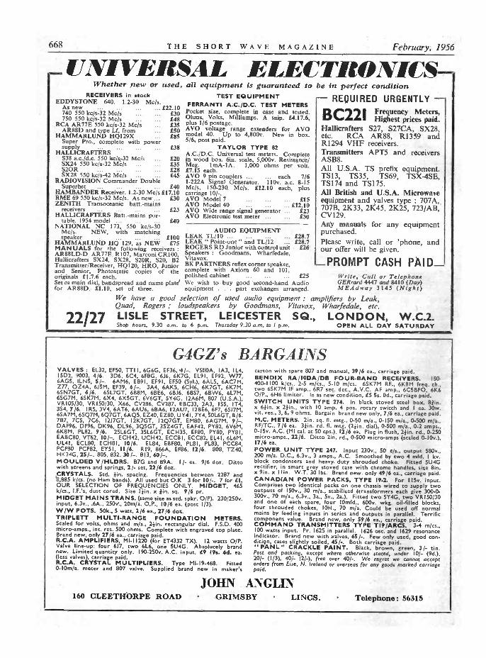
668 THE SHORT WAVE MAGAZINE February, 1956
_ TINI VERSAL ELECTRONICS-Whether new or used,
RECEIVERS in stockEDDYSTONE 640. 1.2-30 Mc/s.
As new ... ... ... ... £22.10740 550 kc/s-32 Mc/s750 550 kc/s-32 Mc/s
RCA AR77E 550 kc/s-32 Mc/sAR88D and type Lf, from
HAMMARLUND HQ129XSuper Pro., complete with powersupply ... ... ... ...
HALLICRAFIERSS38 a.c./d.c. 550 kc/s-32 Mc/sSX24 550 kc/s-32 Mc/sS2ORSX2R 550 kc/s-42 Mc/s
RADIOVISION Commander DoubleSuperhet ... ... ... ... £40
HAMBANDER Receiver. 1.2-30 Mc/s £17.10RME 69 550 kc/s-32 Mc/s. As new ... £30ZENITH Transoceanic batt.-mains
receivers ...
HALLICRAFTERS Batt. -mains por-table. 1954 model ... ... ...
NATIONAL NC 173, 550 kc/s-30Mc/s. NEW, with matchingspeaker ... £100
HAMMARLUND HQ 129, as NEW £75MANUALS for 'he following receivers :AR88LD-D AR77E. R107, Marconi CR100,Hallicrafters SX24, SX28, S2OR, S20, B2Transmitter/Receiver, HQI20, HRO, Juniorand Senior, Photostatic copies of theoriginals £1.7.6 each.Set of main dial, handspread and name plate
£23
£40
£30£48£35£50£85
£38
£20£35£28£45
all equipment is guaranteed toTEST EQUIPMENT
FERRANTI A.C./D.C. TEST METERSPocket size, complete in case and tested.Ohms, Volts, Milliamps. A snip. £4.17.6,plus 1/6 postage.AVO voltage range extenders for AVOmodel 40. Up to 4,800v. New in box.5/6, post paid.
TAYLOR TYPE 82A.C./D.C. Universal test meters. Completein wood box. 61n. scale, 5,000v. Resistance/Meg. 1mA-IA. 1,000 ohms per volt.£7.15 each.AVO 9 pin couplers ... each 7/61-222A Signal Generator. 110v. a.c. 8-15Mc/s, 150-230 Mc/s. £12.10 each, pluscarriage 10/-.AVO Model 7 ... ... £15AVO Model 40 £12.10AVO Wide range signal generator ... £23AVO Electronic test meter ... ... £30
AUDIO EQUIPMENTLEAK TL/10 ... .. ...LEAK " Point -one " and TL/12ROGERS RD Junior with control unitSpeakers : Goodmans, Wharfedale,Vitavox.BK PARTNERS reflex corner speaker,complete with Axiom 60 and 101,polished cabinet ... ... ... £25
£28.7£28.7
£26
We wish to buy good second-hand Audiofor AR88D, £1.10. set of three. equipment . . . part exchanges arranged.
be in perfect condition- REQUIRED URGENTLY -B C2LL2' Frequency Meters,
Highest prices paid.Hallicrafters S27, S27CA, SX28,etc. RCA AR88, R1359 andR1294 VHF receivers.Transmitters APT5 and receiversASB8.All U.S.A. TS prefix equipment.TS13, TS35, TS69, TSX-4SE,TS174 and TSI75.All British and U.S.A. Microwaveequipment and valves type : 707A,707B, 2K33, 2K45, 2K25, 723/AB,CV129.Any manuals for any equipmentpurchased.Please write, call or 'phone, andour offer will be given.
_PROMPT CASH PAID_Write, Call or TelephoneGERrard 4447 and 8410 (Day)MEAdway 3145 (Night)
We have a good selection of used audio equipment : amplifiers by Leak,Quad, Rogers ; loudspeakers by Goodmans, Vita vox, Wharfedale, etc.
22/27 LISLE STREET, LEICESTER SQ., LONDON, W.C.2.Shop hours, 9.30 a.m. to 6 p.m. Thursday 9.30 a.m. to 1 p.m. OPEN ALL DAY SATURDAY
G4GZ's BARGAINSVALVES : EL32, EF50, TTI I, 6G6G, EF36, 4/-. VSII0A, IA3, 114,I5D2, 9003, 4/6. 3D6, 6C4, 6F8G, 616, 6K7G, EL91, EF92, W77,6AGS, ILN5, 5/- 6AM6, EB9I, EF9I, EF50 (Syl.), 6AL5, 6AC7M,Z77, OZ4A, 615M, EF39, 6/-. 3A4, 6AK5, 6CH6, 6K7GT, 6K7M,6SN7GT. 6/6. 6SL7GT, 6B8M, 6BE6, 6B16, 6BS7, 6BW6, 6L7M,6SG7M, 6SK7M, 6X4, 6X5GT, 6V6GT, 5Y4G, I2A6M, 807 (U.S.A.),VRI05/30, VRI50/30, X66, CV286, CV287, EBC33, 2A3, 155, IT4,3S4, 7/6. IRS, 3V4, 6AT6, 6AU6, 6BA6, 12AU7, 128E6, 6F7, 6517M,6SA7M, 6SQ7M, 6Q7GT, 6AQ5, EZ40, EZ80, UY41, 7Y4, 50L6GT, 8/6.7B7, 7C5, 7C6, 1217GT, I2K7GT. I2Q7GT, EM80, 6AG7M, 9/-.DAF96, DF96, DK96, DL96, 3Q5GT, 35Z4GT, EAF42, PY82, 6V6M,6K8M, PL82, 9/6. 25L6GT, 35L6GT, ECH35, EF80, PY80, PY81,EABC80, VT62, 10/-. ECH42, UCH42, ECC8I, ECC82, EL4I, 6L6M,UL41, ECL80, ECH81, 10/6. EL84, EBF80, PL8I, PL83, PCC84,PCF80 PCF82, EYSI, 11/6. R19, 866A, EF86, 12/6. 808, TZ40,HK24G, 25/-. 805. 832. 30/-. 813, 60/-.MOULDED V /HLDRS. B7G and 139A. 1 /- ea. 9/6 doz. Dittowith screens and springs, 2/- set, 22/6 doz.CRYSTALS. Std. /in. spacing. Frequencies between 2287 and8,885 k/cs. (no Ham bands). All used but O.K 3 for 10/-. 7 for El.OUR SELECTION OF FREQUENCIES ONLY. MIDGET, 465k/cs., I.F.'s, dust cored. Size I}in, x }in, sq. 9/6 pr.MIDGET MAINS TRANS. (same size as std. spkr. O/P). 230/250v.input, 6.3v., .6A., 250v., 20m/a. O.P., 10/6 ea. (post 1/3).W/W POTS. 50k., 5 watt, 2/6 ea., 27/6 doz.TRIPLETT MULTI -RANGE FOUNDATION METERS.Scaled for volts, ohms and m/a., 4in, rectangular dial. F.S.D. 400micro -amps., inc. res. 500 ohms. Complete with engraved top plate.Brand new, only 27/6 ea., carriage paid.R.C.A. AMPLIFIERS, MI -11220 (for ET4332 TX). 12 watts 0/P.Valve line-up: four 617, two 6L6. one 5U4G. Absolutely brandnew. Limited quantity only. 190-250v. A.C. input, E9 19s. 6d. ea.(less valves), carriage paid.R.C.A. CRYSTAL MULTIPLIERS. Type MI -19-468. Fitted0-10m/a. meter and 807 valve. Supplied brand new in maker's
carton with spare 807 and manual, 39/6 ea., carriage paid.BENDIX RA/IODA/DB FOUR -BAND RECEIVERS. 150-400-1100 k/cs., 2-5 m/cs., 5-10 mjcs. 6SK7M RF., 6K8M freq. ch.,two 6SK7M IF amp., 6R7 sec. det., A.V.C. AF amp., 6C5BFO, 6K60/P., 6H6 limiter. In as new condition, ES 5s. Od., carriage paid.SWITCH UNITS TYPE 274. In black stoved steel box, Elfin.x 6}in. x 2}in., with 10 amp. 4 pos. rotary switch and 1 ea. 30w.vit. res., 3, 6.9 ohms. Bargain brand new only, 7/6 ea., carriage paid.M.C. METERS. 2in. sq. fl. mtg., 0-50 m/a., 0-I50 m/a., 0-500 m/a.,RF/TC., 7/6 ea. 3}in. rd. fl. mtg. (2}in, dial), 0-500 m/a., 0-2 amps.,0-15v. A.C. (MI cal. at 50 cps.), 12/6 ea. Plug in flush, 24in. rd., 0-250micro -amps., 22/6. Ditto 2in. rd., 0-500 micro -amps (scaled 0-10v.),17/6 ea,POWER UNIT TYPE 247. Input 230v., 50 c/s., output 580v..200 m/a. D.C., 6.3v., 3 amps., A.C. Smoothed by two 4 mfd. I kv.block condensers and heavy duty shrouded choke. Fitted 5Ú4Grectifier, in smart grey stoned case with chrome handles, size 8in.x 9in. x I 1 i. W T. 30 lbs. Brand new only 49/6 ea., carriage paid.CANADIAN POWER PACKS, TYPE 19-2. For 115v. input.Comprises two identical packs on one chassis wired to supply twooutputs of I50v., 30 m/a., stabilised (transformers each give 300-0-300v., 70 m/a., 6.3v., 3a., 5v., 2a.). Fitted two 5Y4G, two VRI50/30and one of each spare, four l0mfd., 600v. wkg. oil -filled blocks,four shrouded chokes, 1OH., 70 m/a. Could be used off normalmains by feeding inputs in series and outputs in parallel. Terrificcomponent value. Brand new, only 59/6 ea., carriage paid.COMMAND TRANSMITTERS TYPE T19 /ARCS. 3-4 m/cs.,100 watts input. Pr. 1625 in parallel. 1626 osc. and 1629 resonanceindicator. Brand new with valves, 65/-. Few only used, good con-dition, cases slightly soiled, 45/-. Both carriage paid." PANL" CRACKLE PAINT. Black, brown, green, 3/- tin.Post and packing, except where otherwise stated, under I0/- (9d.),20/- (1/3), 40/- (2/.), free over 40/-. We regret we cannot acceptorders from Eire, N. Ireland or overseas for any goods marked carriagepaid.
JOHN ANGLIN160 CLEETHORPE ROAD GRIMSBY LINCS. Telephone: 56315

Volume X111 THE SHORT WAVE MAGAZINE 669
PROFESSIONAL CAREERSFOR AMATEUR RADIO ENGINEERS
Several permanent posts are available for technicianshaving a flair for communication engineering. Im-mediate vacancies for :- designers, developmentengineers, draughtsmen, test engineers. Seniorpositions are open to selected applicants willing totake responsibility.
Please apply giving full particulars to :-
LABGEAR (Cambridge) LTD.WILLOW PLACE, CAMBRIDGE.
SMALL ADVERTISEMENTS9d. per word, minimum charge 12/-. No series discount; all chargespayable with order. Insertions of radio interest only accepted. Add25". for Bold Face (Heavy Type). No responsibility accepted forerrors. Replies to Box Numbers should be addressed to The Short
Wave Magazine, 55 Victoria Street, S.W.1.
APPOINTMENTSTECHNICAL ASSISTANT required with good
knowledge of radio for the assembly and testingof electronic instruments. MITCHAM 2007.-Box1656, Short Wave Magazine, Ltd., 55 Victoria Street,London, S.W.1.
ELECTRONIC CIRCUITRY INSPECTORrequired at the Nelson Research Laboratories,English Electric Co., Ltd., Stafford, to inspectprototype electronic equipment. Applicants musthave had workshop experience and be familiar withthe standards required by Government departments.C. & G. Int. Cert. in Telecommunications Engineeringor O.N.C. desirable, but not essential. Write withfull details to Dept. C.P.S., 336/7 Strand, W.C.2,quoting Ref. 305M.
MINISTRY of TRANSPORT andCIVIL AVIATION
RADIO TECHNICIANSAPPOINTMENTS are available for interesting
work providing and maintaining aeronauticaltelecommunications and electronic navigational aidsat aerodromes and radio stations in various parts ofthe U.K. Applications invited from men aged 19 orover who have fundamental knowledge of radio orradar with some practical experience. Trainingcourses provided to give familiarity with types ofequipment used. Salary £536 age 25 rising (subjectto a practical test) to £635. Rates lower in Provincesand for those below age 25. Prospects of permanentpensionable posts for those who qualify. Opportuni-ties for promotion to Telecommunications TechnicalOfficer are good for those who obtain O.N.C. inElectrical Engineering or certain C. and G. Certs.Max. salaries of Telecommunications TechnicalOfficers : Grade III £725, Grade II £850, Grade I,£1,045. Apply to the Ministry of Transport andCivil Aviation. ESB1/6057, Berkeley Square House,London, W.1, or any Labour Exchange quotingOrder No. Westminster 6627.
Thisis
Candlercalling ;
ALL ENTHUSIASTSwishing to learn or toimprove their speed andaccuracy in Morse Code.The Candler System of homestudy and practice embodies ex-clusive methods for quicklylearning to read and send MorseCode. The Practice Equipmentcosts only a few shillings.
Thirty minutes of guided practice a day, the Candler way,is more beneficial than hours spent in hit and missmethods. This System is recognised throughout theWorld as the most efficient, simple and scientific methodof Morse Code Training.These are three Courses available :(I) THE SPECIAL SHORT COURSEFor G.P.O. Morse Code test for securingAmateur Transmitting Licence, and forS.W.L's.(2) THE JUNIOR COURSEA Complete Course for the Beginner.(3) THE ADVANCED COURSEFor all who desire to increase their accuracyand speeds up to 20 or more w.p.m.For Terms and Full Details, write for the " BOOK OF FACTS "
which is sent post free, without any obligation.
CANDLER SYSTEM CO.(Dept. 55 S.W.) 55b ABINGDON ROAD, LONDON, W.8.
Candler System Company, Denver, Colorado, U.S.A.
LYONS RADIOLIMITED
3, Goldhawk Rd., Shepherds Bush, London, W,I2Dept. MS. Telephone : SHEPHERDS BUSH 1729
BEAT FREQUENCY OSCILLATORS. These instruments byFurzehill Laboratories have a continuously variable frequencyrange from 0/I0 Kc/s. with a 50 cycle check point. Incorporatetheir own internal power pack for operation from 100/120v. and200/250v. A.C. 50 cycle mains. Output impedance 10 or 600 ohms,monitored by 2 -range 0/5 and 0/50v. A.C. rectifier type voltmeter.Valve line-up : 3-HL4's, X41, PX4, MU14. Housed in metal in-strument cases, approximately 17 x 10 x 9in., with lifting handleson side. In good working order. PRICE £8/1216, carriage 7/6.BAND III CONVERTERS (for all areas). Using three valves(2-Z77, 1-B309), these Converters can be used with TRF. orSuperhet Band 1 TV. receivers. They contain their own powerpack for operation from 200/250v. A.C. mains and are ready forimmediate use. Housed in smart walnut veneer cabinets, approxi-mately 10 x 5 x 6fin. Supplied complete with all valves and in-structions. PRICE E7/IO/-, post 3/6.BAND III CONVERTER KITS. Complete coil kit by TeletronCo., with circuit, point-to-point wiring diagram, alignment in-structions, etc. Provides the basis for an efficient easy to make 2 -valve converter which can be relied upon to give good results.For use with TRF. or Superhet Band 1 TV. reéeivers. Mk. I. Twopentode version for Service area. PRICE 15/-, post 6d. Mk. II.Cascode, triode -pentode version giving higher gain for the poorerreception areas, PRICE 17/6, post 6d. Ready drilled chassis,PRICE 3/9, post 6d. Data leaflets only 3d. each, post 1 or 2, 3d.TRANSMITTER/RECEIVERS, TYPE 22. Frequency range intwo switched bands; 2-4.5 Mc/s. and 4.5-8 Mc/s. Controls includeR/T. and C/W. switch with provision for netting and 2in. diameterswitched meter mounted on panel for checking operating voltages.Fitted with 13 valves (5-ARPI2's, 2-AR8's, 3-VT52's, and I eachARP34, CV65 and ARDD5) and separate power pack for 12v. D.C.input. Overall size, including power pack, approximately 23 x II x8in. In fair condition. PRICE L4/19/6, carriage 12/6.BC -SIB PLATE TRANSFORMERS. Primary 115v. 50-60 cycles.Secondary 2,000v. or 2,500v. at 500 mA. centre tapped. Size9in. high x 12 x I lin. As new and unused in original packing cases.PRICE E7/10/-, sent carriage forward.SPEAKER GRILLE. Woven metal, three sizes available : 'A'141 x 13}in. ; ' B ' 15 x 12in. ; ' C' 161 x I Ilin. With smart gold -
sprayed finish. PRICE, any size, 3/6, post paid.
670 THE SHORT WAVE MAGAZINE February, 1956
SURPLUSGENUINE AMERICAN ARMOUR RECORDING WIREin sealed tins on International Spools. One hour speech, half-hourmusic. 15/- (2/-).
STEP-DOWN TRANSFORMERS, all 230/115v. Totallyenclosed, double wound by G.E.0 250w. E2 (5/-). 500w. E3/5/-(7/6). 1,000w. E4/10/- (20/-e).AUDIO TRANSFORMERS. R.C.A. modulation for ET.4336CT Primary, I5/- (2/6). Woden 100w. Pri. 1700(1. 20002 CT.Sec. 5000, 60002 CT. 20 lbs., 35/- (20/-).RADIO TRANSFORMERS. All Primaries, 200/250v. RCAFilament, 10v. 3.25 a. C.T. twice, 15/- (2/6). 26 to 38v. 11 ampsand 120 to 160v. 600 m/a, 24/- (3/6). Woden 14v. 6a. ; 4.5v. 4.5a. ;4.5v. 2.5a ; 25/- (14/-*). Woden 640v. 400 m/a not C.T. ; 4v.3a. twice, 25/- (15/-'). Woden 1500v. 400 m/a (not C.T.), 45/-(15/-'). Woden 7.5v. 12.5a. ; 4v. 6a. ; 4v. 4a. ; 4v. 3a., all C.T.,35/- (17/6').VALVES, all guaranteed. AL -60, I0/- ; 1DA-30, 15 /- ; DET-12,20/-; RG-I, I0/-; 6SJ7, 5/-; 6V6, 5/-; 6C5, 5/-; 6K7, 5/-;6SL7, S/-; 4212E, 60/- ; 830B, 20/-.P.O. RACKS. 19in. wide, drilled and tapped, channel sides, 36in.high, 40/- (10/-).CABI NETS. A.R.88 pattern, hinged top, black crackle, 70/-(15/.*)CHOKES. Woden 20H400m/a,25/-(15/-'). Federal IOH 10 m/a.,2/6 (1/-).Amount in brackets is carriage. includes returnable case charged10/-.
Full Lists available. Vast quantity Ham equipment.
P. HARRIS, ORGANFORD, DORSET
There's always good value at-The ('Valk-axouad stop
BENDIX RECEIVER Type MN. 26C. RADIO COMPASS.A superb 12 -valve 3 -band receiver covering 150-1,500 kc/s. I.F. Fre-quency 112 kc/s. Valve line-up : 6K7 1st and 2nd R.F. 6L7 Mixer.6J5, OSC, 6K7 I.F. Amp. 6B8 1st and 2nd Det and A.V.C. 615 B.F.O.6F6 audio output. Compass Mod. 6N7, audio oscillator 6N7. LoopAmp. 6K7. Compass output 6K7. 28 volt supply to Motor Generatorwhich can be easily changed to 12 volts (details available). Circuits, etc.Free with each unit. The Perfect Car Radio. Size : 15}in. xI I}in. x 6in. Power supply 6.3v. 250v. PRICE £3/101-, plus 7/6 packag-ing and carriage.
POWER PACK Type 173.12 to 24 volt I.t. input. 120v. 60mA output. Fully smoothed size, 104in.x 6in. x 3in. Containing two 120 volt 60mA selenium rectifiers. OneV.S.I10 voltage stabiliser ; 12 volt vibrator and trans. chokes, etc.,12/6 post paid.MAKE A MINIATURE POCKET RADIO.lrcorporating high " Q " technique using the new Ferrite rod. Madepossible by simple conversion of an ex -Govt. hearing aid. £2/61- postpaid, with circuit diagram and full instructions. Batteries extra : 1.5v.I.t. (type D18), 8d. ; 30v. h.t. (type BI19), 4/3.F.L.8a FILTERS.Splendid value, 10/-, packing and postage 1/6.R.F. UNITS.R.F.24 20/30 Mc/s, switched tuning, fully valved, 9/6 each. R.F.25 40/.50 Mc/s, switched tuning, fully valved, 9/6 each.INDICATOR Type 62A.Ideal for conversion to oscilloscopes, TV. units, etc. Containing V.C.R.97, 12 VE9I (EF50), 2 VR54 (E834), 3 VE92 (EA50), 4 CVII8. Slow-motiondial. 13 pots and scores of useful components. Size 8}in. x I I}in. x IBin.New. In wooden packing case, price £3, carr. 7/6.
NOTE : Orders and Enquiries to Dept. ' S.'
PROOFSBROS., LTD. LANgham :52 Tottenham Court Road, W.I. 0141
Hours 9-6 p.m. Thursday to 1 p.m Open all day Saturday.
TRADESL CARDS AND LOG BOOKS. APPROVEDG.P.O. SAMPLES FREE. - ATKINSON
BROS., PRINTERS, ELLAND, YORKS.
WANTED: BC -610 Hallicrafters, ET -4336 Trans-mitters and spare parts for same. Best prices.
-P.C.A. Radio, Beavor Lane, Hammersmith, W.6.
QSL's and LOGS by MINERVA. The best thereare.-Samples from Minerva Press, 48 Queen's
Road, Brentwood, Essex.
G3CGD QSLs. Samples of FIXED or MOBILEcards on request. -30 St. Luke's Road, Chelten-
ham, Glos.
YOUR VOLUME XIII SHORT WAVE MAGA-ZINE BOUND. First class full library binding,
I 2s. 6d.-Underwood, Earls Road, Amesbury. Wilts.
MOBILES: Overprint your QSL card with aRubber Stamp, 7s. 6d. - G2FSR, 2 Parkhill
Road, Chingford, E.4.
READERS' ADVERTISEMENTS3d. per word, min. charge 5/-, payable with order. Box Numbers1/6 extra. Replies to Box Numbers should be addressed to The
Short Wave Magazine, SS Victoria Street, S.W.1.
JERSEY HOLIDAY.-Near sea, town centre. Hamshack. Photographic dark-room.-Write brochure:
GC3KPO, The Lincoln, 3 Saviour's Road, St. Helier,Jersey, C.I.
VI J ANTED: Power pack for SP400 ; exchangei Primarreflex camera, interchangeable f2.8 lens,
FP shutter to 1/1000 sec. for mint HRO, HQ129,AR88, or similar Rx. Camera accessories available.-Box 1647, Short Wave Magazine, Ltd., 55 VictoriaStreet, London, S.W.1.
AR77E, good condition, speaker, RCA manual,£20, or exchange for SX28, AR88D. Cash
adjustment. Also selling home made six valveCommunications Receiver. Plug in coils, 10, 20, 40.Power pack, Eddystone parts, needs slight attention,£4 10s. Buyer collects.-Blane, 62 Hewlett Road,Bow, London, E.3.
FL8 filter, £1 ; Class D wavemeter, 100kc, £3 10s.;Lionel Bug, 30/- ; Brown m/c headphones, £1 ;
80 metre VFO, two buffers, professional, mains,£5 10s.; BC -348 AC, £15 ; PP807 PA, 120 watt,speech amp. and mod., 1000v 500 mA power pack,Eddystone rack, UM3, metered, £20. Other gearcheap.-G3FAB, 4 Point Road, Canvey Island, Essex.
SURPLUS EQUIPMENT for sale. Nothing over£1. Transformers, microphones, rectifiers, electric
motors, etc. Stamped addressed envelope for listto.-G6BS, 96 Hinton Way, Gt. Shelford, Cambridge.
WANTED: Two Metre Receiver and BeamAerial.-Box 1648, Short Wave Magazine Ltd.,
55 Victoria Street, S.W.1.
WANTED: Hallicrafter SX28, also American bugkey. State condition and price.-Box 1649,
Short Wave Magazine, Ltd., 55 Victoria Street,London, S.W.1.

Volume XIII THE SHORT WAVE MAGAZINE 671
SMALL ADVERTISEMENTS, READERS-Continued
BC342N with matched speaker. Perfect workingorder, modified as in QST, £13.- Ingram,
49 Lime Tree Avenue, Broadway Worcestershire.
WANTED: BC453B Receiver. LG300 Tx.Windcharger. Recording Barograph. Hand -
hearing compass.-Box 1650, Short Wave Magazine.Ltd., 55 Victoria Street, London, S.W.1.
Br -1342D, good condition, 110/230v. Covers 160to 10 metres, £10. Carriage paid.-Atkinson,
29 Plains Lane. Elland, Yorks.
A R 88F for sale. Perfect condition. S -meter.Manual. Realigned, £50 o.n.o. Plus Car-
riage. Prefer collect.-Webley, Widdicombe, RedhillAvenue, Bournemouth.
EDDYSTONE 750. excellent condition and per-formance. WANTED: CR100 or similar. -41
Appleton Street, Northwich, Cheshire.
ROOM wanted. semi or unfurnished by ham inUSA to store gear. Near London, but if
possible where mast for long distance transmittingcan be erected. Probably returning Summer, whenweekend visits would be paid and some cookingfacilities would be helpful. Terms by arrangementwith Mrs. Swithinbank. 28 North Park. Eltham,S.E.9. ELT. 2183. (G3FXY).
ONCE ONLY BARGAINS. HALLICRAFTERSSX28 COMMUNICATIONS RECEIVER.
GOOD CONDITION, £30. B2 TRANSMITTER/RECEIVER. COMPLETE ACCESSORIES, SPARES.HANDBOOK. ALMOST NEW, £16. CARRIAGEBOTH PLEASE. - 369 GLASGOW ROAD,WISHAW, LANARKSHIRE.
FORSALE : Hallicrafter Skyrider SX24, £16
(o.n.o.). Power unit 620v 250mA. 375v 250mA.£5. Various valves S.A.E. for list.-A. I. Morrison.GM3HFU: 134 Duff Street, Macduff.
GUARANTEED: EF50 (fifteen). 6SN7 (two),PTI5 (two), 8011 (two), 0.1 µF 7KV (two),
0.01 /IF 5KV (two), 600v DC 20 mA (two) Rectifiers.Post extra.-V. A. Cedar, 9 North Drive. S.W.16.
B2COMPLETE, spares, manual, £9. Manualsfor HRO and SX28, 10/- each.-Box 1651,
Short Wave Magazine. Ltd., 55 Victoria Street,London. S.W.I.
MORECAMBE HOLIDAY : Overlooking bay andLake District mountains. Ham Shack. Write
brochure.-G3AEP. Ferncliffe Guest House, DrewtonAvenue, Sandylands, Morecambe.
WANTED : Transmitter Type No. 12. Up to £20paid for set in mint condition. - Box 1652,
Short Wave Magazine, Ltd., 55 Victoria Street,London, S.W.1.
£1 4n OFFERED for. Collins 75A2 or £100 for75A1 ; sell or part exchange AR88D £55;
S640 £18 10s. BC22IAJ £27 10s.-G6XY, 233Warwick Road, Kenilworth. (Tel. 679).
HRO Coils 1.7-4, 3.5-7.5, 7-14 mc, 35/- each. WantHambander, BC -455. Replies to s.a.e. only.-
Loader, Mudeford Farm, Mudeford, Hants.
Wanted
10221Frequency Meters
£26 PAIR
Largest stocks in Europe of GovernmentSurplus material.
ALTHAM RADIO COMPANYJERSEY HOUSE, JERSEY STREET, MANCHESTER 4.
Telephone : Central 7834/5/6.
Southern Radio's Wireless BargainsTRANSRECEIVERS. Type " 38 " (Walkie -Talkie). Complete
with 5 -valves. In Metal Carrying Case. Ready for use. Lessexternal attachments per set 30/ -ATTACHMENTS for use with " 38 " TRANSRECEIVERHEADPHONES, 15/6 ; THROAT MICROPHONE withLead and Plug, 4/6 ; JUNCTION BOX, 2/6 ; AERIAL, 2/6 ;SPECIAL OFFER of used " 38 " TRANSRECEIVERS less Valvesbut complete with ALL COMPONENTS. Excellent forSPARES per set 11/6 P & P 2/-
TRANSRECEIVERS. Type " 18" Mark Ill. TWO UNITS(Receiver and Sender) contained in Metal Case. Completewith six valves, microammeter, etc. LESS EXTERNALATTACHMENTS £4 / 101 -
RECEIVERS. Type " 109" 8 -valve S.W. Receiver withVIBRATOR PACK for 6 -volts. Built-in Speaker ; METALCASE ES
BOMBSIGHT COMPUTERS. Ex R.A.F. BRAND NEW.A wealth of components. GYRO MOTORS : REV COUNTERS;GEAR WHEELS, etc., etc. Ideal for Model Makers, Experi-menters, etc. E3
LUFBRA HOLE CUTTERS. Adjustable r to 31-. ForMetal, wood, plastic, etc. 6/6
RESISTANCES. 100 ASSORTED USEFUL VALUES. WireEnded per 100 12/6
CONDENSERS. 100 ASSORTED. Mica Metal Tubular, etc.per 100 IS/ -
PLASTIC CASES. 14" x 10r. Transparent. Ideal for Maps,Display, etc. 5/6
STAR IDENTIFIERS. Type I A -N covers both hemispheres.In case 5/6
CONTACTOR TIME SWITCHES. In sound -proof case.Clockwork movement ; two impulses per sec. Thermostaticcontrol 1 I /6. REMOTE CONTACTORS for use with above 7/6
MORSE TAPPERS. Standard, 3/6. Midget 2/9MORSE PRACTICE SET with buzzer on base 6/9Complete with battery 9/6
METERS AND AIRCRAFT INSTRUMENTS. Only needadjustment or with broken cases. TWELVE INSTRUMENTSincluding 3 brand new Aircraft Instruments 35/- for 12
CRYSTAL MONITORS. Type 2. New in transit case Lessvalves 8 /-
Postage or Carriage extra. Full List of Radio Books 21d.
SOUTHERN RADIO SUPPLY LTD.II, LITTLE NEWPORT STREET, LONDON, W.C.2.
GERrard 6653

672 THE SHORT WAVE MAGAZINE February, 1956
SMALL ADVERTISEMENTS, READERS-Continued
53, Q5', FB nn, ; Ms / W CB 4mandRxer, modified
coditioAudio £3,£2 lOs.; Type 105om-
unit, as new, £2. WANTED : BC -454 or 1.5-3mcCommand set and manual. - SWL. 112 AttoxhallRoad, Coventry.
HRO Senior, fitted with noise limiter and two coilpacks 3mc-7mc and 14mc-28mc, £17. Slight
attention needed to RF stage.-G. Newton, MuriestonHouse, Midcalder, Midlothian, Scotland.
FOR SALE : CR100, £12 10s. Buyer collects.S.a.e. please for enquiries.-R. A. Burnett, 19
Stockwell Road, East Grinstead, Sussex.
VALVE SALE : EF91, EF92, EB91 all at 5/-;EF37, EL32, 6B8 all at 4/-. Many others to
clear, all money back guarantee.-W. Edwards. 199Tarbock Road, Huyton, Lancs.
HRO Senior, 3 b/s coils, £12 ; Minescope withcase, £5 10s.; AC power supply for 1132
Receiver, £1 10s.; 19 Tx and Rx with 12 volt powerunit, £2 10s.; 50 volt 50 cycle Selsyns 20/- pair ;Ferranti 1000 o.p.v. 3in Mc meter, 0-150 volts 15/ -.-Box 1653, Short Wave Magazine Ltd., 55 VictoriaStreet, London, S.W.1.
WANTED: Woden UM2 Mod. Transformer.Woden DTI Driver Transformer 5R4G
Rectifiers (two).-Box 1658, Short Wave Magazine,Ltd., 55 Victoria Street, S.W.1.
A R 88LF fitted Webb's S -meter, handbook, £40.Two 1131 RF power units with rectifiers, £5
each.-G2JD, 22 Bromeswell Road, Ipswich, Suffolk.
FOR SALE: BC -348 Receiver, 1481 Receivermodified ten metre reception, 5 metre converter
and 10in. Amplion loudspeaker, £25 or near offer.-Tel. Tulse Hill 7002 evenings. J. B. Rogers, 25Brading Road, London, S.W.2.
45 rT. LATTICE TOWER in three 15ft. sections(American), dismantled but complete, £25. 1131
VHF Transmitter. Modified for ham bands in 6ft.enclosed rack, includes a 250 watt modulator, two1000v 250mA power units, etc. complete, £25.-Box1655, Short Wave Magazine, Ltd., 55 Victoria Street,London, S.W.I..
FOR SALE: Canadian VRL, nineteen valve Com-munications Receiver with instruction manual.
230 volt AC mains. Full coverage 1.4 to 29mc.Nineteen spare valves, £25. ALSO: 50 watt phoneCW Transmitter crystal controlled, high levelmodulated, PA 807, modulators two KT66. Micro-phone and key, £12. ALSO : New Zealand wirelessset ZC1 MK1 complete 12 volt mobile transmitter/receiver for 80 metres, 9 watts phone, 15 watts CW,6L6 PA VFO and separate 12 volt power pack foruse on 230 volt AC mains, £10. All above equip-ment it is preferred buyer collects. Also for sale:A number of back issues of Short Wave Magazineand RSGB Bulletins and Radio textbooks.-Spashett,81 Annesley Street, Grimsby.
Tx/Rx complete with small screen mod. £15.-G VQ4CW, Standard Bank, Molo, Kenya.
WANTED: One pair of AR88 trimming tools.Manual or Circuit for PSE1, 2 valve (EF8's)
Preselector 0.52-43 mc. Hallicrafter S27 manual.-J.Jackson, 24 High Street, Crail, Fifeshire.
SMALL ADVERTISEMENTS, READERS-continued
WANTED: BC -1161A, BC -453A, S36 and S37 ;RCA Junior Voltohmyst ; Panoramic Adaptor
for 450-465kc IF ; RA62 power pack ; R54/APR4and tuning units. FOR SALE: TS47/AP4 SignalGenerator 40-500mc.-Box 1657, Short Wave Maga-zine, Ltd., 55 Victoria Street, S.W.1.
SALE: HRO5 (metal valves) Table Model, manual.Coils, 0.9-30 mc bandspread 80, 40, 20, 15 and
10 metres. Also complete set (9) GC coils tropical-ised. Coil cabinet, rack mounting for 10 coils. Spare14-30 mc GC coil. Ditto 1.7-4 mc bandspread. BC -348, internal power pack, 230v. AC, 6F6 output,speaker, manual. AR77E revalved and overhauled.speaker, manual. SX28 speaker. RF26 new unmodi-field. RF27 modified for 144 mc. Delivery reason-able distance.-G3JIE, c/o 25 Russell Avenue,Sprowston, Norwich.
WANTED by Amateur. Hammarlund HQ129XReceiver in good condition. Any reasonable
price paid. Collection can probably be arranged.-Box 1654, Short Wave Magazine, Ltd., 55 VictoriaStreet, London, S.W.1.
SLE : Soundmaster tape recorder, less case andAspeaker,as new. Offers over £35. 1155N, £14 ;
1155A, £8. Both internal p.p. and output. WANTED:UM2 or UM3 Modulation Transformer.-J. Read, 4Wendover Drive, New Halden. Surrey. (Malden4455.)
Short Wave Magazine Advertising givesWorld -Wide Coverage.
WANTED:BC221 FREQUENCY METERS
WANTED FOR EXPORT
High Price paid for those in good conditionand complete. CASH IMMEDIATE
Send, or write, to
De Tollenaere23 Despard Road Archway London N.19
BRASS, COPPER, BRONZE,ALUMINIUM, LIGHT ALLOYSIN ROD, BAR, SHEET, TUBE, STRIP, WIRE
3000 STANDARD STOCK SIZES
H. ROLLET & CO., LTD.6, CHESHAM PLACE, LONDON, S.W.I.
SLOane 3463
Works: 36 ROSEBERY AVENUE, LONDON, E.C.I.Branches at LIVERPOOL MANCHESTER, BIRMINGHAM, LEEDS
"No Quantity too Small"
Volume XIII THE SHORT WAVE MAGAZINE iii
G2AK THIS MONTH'S BARGAINS G2AKTHERE IS NO EXCUSE NOW
for not being on phone or for nothaving a nice clear signal.
CRYSTAL HANDMICROPHONES
DEAF MD CRYSTAL MIKE UNITS,7/6 each cr 12/- for two, post and packing, 9d.
COPPER WIRE. 14G. H/D 140ft., 15/-;70ft., 7/6. Post and packing 2/-. Otherlengths pro rata.
RACK MOUNTING PANELS. 19" x 51",7", 8}", or I0i", black crackle finish, 5/9,6/6, 7/6, 9/- respectively, postage andpacking 1/6.ABSORPTION WAVEMETERS. 3.00 to35.00 Mc/s in 3 Switched Bands. 3.5, 7, 14.21 and 28 Mc/s Ham Bands marked on scale.Complete with indicator bulb. A MUST for
As illustrated, in any Ham shack. Only 15/- each. Post andpacking II-.
silver hammer case HEAVY DUTY POWER TRANS -with polished grille, FORMER. 0-240 tapped primary. Sec.
350/350 25CmA., 5V. 2.5A, 6.3V. 3A, 24V. SAhandle and 4 -feet of (tapped 6.3 and 12.6V.), 39/6 p. and p. 2/6.
screened lead. DUAL OUTPUT POWER UNITS byHallicrafter. Input 12V. D.C. Output(vibrator) 250V. 70mA, dynamotor 350165mA. All fully smoothed and filter fullyrelay controlled. In grey finished steel case.All new in original cartons, only [4/17/6.carriage paid England.
EDDYSTONE, WODEN, RAYMART, AVO, etc., COMPONENTS AND A GOODRANGE OF COMMUNICATION RECEIVERS ALWAYS AVAILABLE.
ONLY 21 /-Post paid.
No C.O D. on Orders under LI
CHAS. H. YOUNG, G2AK
PARMEKO H/D Transformer, 230v. pri.620/620v. 200 mA. Tapped 550v. and 375v.250 mA. 5v. 3A., 5v. 3A. 63, carriage paid.
STREAMLINED BUG KEYS by famousmaker. Brand new in cartons. Listed over 64.Our price, 45/- only.
MINIATURE ROTARY TRANSFOR-MERS. Input 12v. Output 360/310v., 30 mAc.c.s. or 70 mA i.c. a.s. Only 41in. x 21in.overall. Only 17/6 each, or 30/- for 2.Post and packing 1,16.
Don't miss these BargainsPOWER UNITS in Black Metal Case.With input and output sockets. For 200/260v.50c Input ; Output 200/250v. 60/8) mA.Fully smoothed and fused. Also gives 31 v..3A D.C. and 6.3v. 3A A.0 fitted with 6X5rectifier. 50/- each, carriage paid.MODULATION TRANSFORM=RS. 'Ex522 TX(. Useful to 15,N audio Very limit_dquantity. 7/6 each. Post and packing I/-.500 PF PI Output Circuit Tuning Condensers.1.500v. rating, ceramic ins. 15/- only.Worth double.
PLEASE PRINT YOUR NAVE AND ADDRESS
MAIL ORDERS TO : Dept. " S "102 Holloway Head, BirminghamALL CALLERS TO :- 110 Dale End, Birmingham.
MIDLAND 3254
CENTRAL 1635
A 2 -Metre Conrertorof
Outstanding :Merit,
4-6 Mc/s. I.F. - Crystal controlled. - Low noisetriodes. - Adjustable matching.
PRICE, complete with valves and overtone crystal,£91101- (Cat. No. E5030/A) ; or with power unit
and cabinet, [I5 (Cat. No. E.5030).
Labge«r (Cambridge) Ltd.WILLOW PLACE, CAMBRIDGE. Tel. 2494
BROOKESCSj
mean DEPENDABLEfrequency control
Illustrated aboveis o Type OB Crystalunit with a frequencyrange of 50-110 kris.Frequency Tolerance± .005% of nominalat 20'C.
ALL Brookes Crystals Ore made to exactingstandards and close tolerances. They areavailable with a variety of bases and in awide range of frequencies. There is a BrookesCrystal to suit your purpose -let us haveyour enquiry now.
Brookes Crystals LtdSuppliers to Ministry of Supply, Home Office, BBC, etc,
181/183 TRAFALGAR RD., LONDON, S.E.I0Tel. GREenwich 1828. Grams: Xtals Green, London.
"R.F.26" F.M. CONVERTOR UNIT -88/100 Mc/s.We can now offer this self contained Unit comprising 6 Valves-2-6BA6,EB91, VR137, EF54, EF54. Two I.F. stages and separate local oscillatoralso Muirhead graduated vernier drive assuring easy tuningComponents offered to complete F.M. Unit :* New RF26 Unit with 3 valves, VR137. EF54, EF54. LI/I2/-.* Complete set of all components for conversion including 2 6BA6 and
EB9I, tuning condenser, I.F.T.'s Osc. and coils. Resistors and fixedcondensers, plus wire and tag strips. 14/10/6.
* Instruction Book with technical circuit and complete lay -out diagrams.1/6.
* Voltage required 250 v. 50 mA. 6.3 2 amps.* Special offer of all above items and RF26, including circuit, [6/5/-, post. 3/-.ALL ITEMS SOLD SEPARATELY* Charge for alignment when completed 7 6
* Assembled, aligned and ready for use £8 10 0
Call for demonstration.
BIRANI HIGH VACUUM TEST EQUIPMENTManufactured by Pye Radio for atomic research, comprising Birani ControlUnit, Bridge Unit, Gauge Head with calibrator and Pye Scale Lamp Galvo.All items brand new in original packet, [35 complete (spare Birani heads,Edwards M6, 15/-).
`*4sáFREO-KC.-CHANNEL
271271
winsioex.111,-
QUARTZ CRYSTALSType FT243 Fundamental frequencies, 2 -pin,tin spacing.200 types in the following frequencies : 5,675 Kc/sco 8,650 Kc/s in steps of 25 Kc1s. 5,706 Kc's to8.340 in steps of 33.333 Kc/s.
All Brand New 10/- eachSpecial price for complete sets of 80 or 120.
Above are ideal for re -grinding.
Type FT24IA. 54th Harmonic. 2 -pin }in.spacing.
Mc/s. Mc/s.Mc's Mc s 21.5 26.021.1 23.2 22.0 26.121.2 23.4 22.8 26.421.4 24.4 22.9 27.0
Brand New and G d. 7/6 each.
FT24IA 200 Kc/s., 10 /-. FT24IA, 465 Kc s , 10 /-
PHOTO -ELECTRIC CELLSBrand New and Booed. 4 -Pin U.X. base. Baird GS18-U.S.A. 71 A - 868 ... ... ... ... 17 /6 each
ID8GTIG6R554SST4A7GTA5GTH5GTNSGTCSGTQ5GTL4LN5LDS
2X23A43Q43V43543Q5GTSU4GSY3GT5Z35Z4G6A7G6A66C66D66AC76AG7688
We have over 50,000 American and B.V.A. valves in stock
IO/-
ALL VALVES NEW AND GUARANTEED10/- 6C4 7/6 6R7M 8/6 I2SH7GT 7/6 1299A 4 /6 HL23,DD 6/66/6'6CSM 5/- 6R7G 8/6 125C7 10/- ATP4 4/- PEN46 7/6
7j6 6FSGT 7/6 6SC7M6S57M 17%6 12517- QT 86 CKSIOAX6 5-% QP2I 8%6
7/6 615GT7j6 615M
5/- 65G7M5/- 6X5GT
6/68/6
12SK712SR7
8/67/6
DID42
5/-5 /-
Q6130
SP414-
10/- 6AM6 9/- 65H7 6/6 14A7 8/6 D63 5 /- 4/-10/- 6AGS 7/6 6SA7 8/6 25A6G 10/- EA50 2/- TP2210/- 6BA6 8/6 6SA7 8/6 25Z5 8/6 EB34 3 TH233 10%-
10/- 6F6G 7/6 6SN7GT 9/- 2SZ6GT 8/6 EBC33 6/6 U17 5-10/- 6BE6 10/- 6SL7GT 9/- 35Z4GT 8/6 EF36 6/6 U19 10%-
10/- 6V6G 7/6 6517 8/6 35Z5GT 8/6 EF39 6/6 U22 8/67/67/6
6V6GT6V6M
7/6,6SK710/- 7C5
7/68/6
35L6GT50L6GT
8/68/6
ECH35SPI3C
12%6 U52VP23
8/66/6
7/6 616 9/- 7A7 8/6 SOBS 10/- VP13C %4- VP4I 7/65/- 6AK5 9/- 7C7 8/6 5005 10/- EF9I 9 /- VUI33 4/-9/-9/-
6USG6170
7/6 71-176/6 787
8168 /6
4246
8/610 /-
51391 9 /-EF50 (Ex -Units) 0AVT501 7/6
7/6 617M 8/6 757 10/- 75 8/6 51- VR105'30 8/67/6 6K7G 6/6 8D2 4/- 80 8/5 EF50 (Red Syl) VR150'30 8/6
10/- 6K7GT 6/6 9D2 4/- 807E 7/6 1St- STV/280/40 15 /-8/6 6K7M 7/6 4D1 4/- 807USA 10/- EF54 5130 7/68 /6 6K6GT 8/6 2A6 7/6 803 35 /- EL72 7%6 VS70 (7475) 7/68/6 6G6G 6/6 2C8GT 7/6 805 35/-
17/6XH (2v) /-
8/68/6
6H6GT6H6M
4/-5/-
21-162K7GT
7/68/6
81385bA
105 /-12/6
KTW6IKTW62 7/6
XPY63
(1.40%86
10/- 6K8GT 9/- 2AH7GT 8/6 872A 21 /- KTW63 7/6 TZ40 35/-6/6 6L6G 10/- 2K8GT 8/6 9001 2 3 6/- KT33C 101- R3 8/66/6 1622 (6L6) 11 I- 2Q7GT 8/6 9004 6 /- KT61 10 /- OZ4 7 /-6/6 6L7M 8/6 2SA7GT 8/6 9006 5 /- KT66 12/6 OZ4A 7 /-
6N7GT 7/6 2SQ7GT 8/6 954 5/- GL466A 15/-7/6 6Q7GT 8/6 2SG7 8/6 956,7 6/- PEN25 6j6 003/W 8/6
OBSOLETE TYPES (Available from Stock)LP2 3/6 VP2 8/6 TDD2A 8/6 U10 8/6 PENDD4020 MH4210LF 3/6 SP2 8/6 FC13S'C 10/- DDL4 4/- 12/6 2D4AP2 4/- VP2B 8/6 FC13C 10/- 354V 5/- 1626
2155G 4/- TP22 81- MS'PEN 7/6 42SPT 6/- ML4 7/6 1629
5 /-4/-7/68/6
EBC41EY51EF4IEL41EZ40EM34UL4IUY41UF4I
10 /-
II/-11/-10/-10/-11 /-II /-I I /-
UCH47UBC4IDK40EF80EABC80ECCBSEF80ECL80PL8 I
LATEST TYPES NOW IN12/6 PL82 10/- 12AT710/- PY8I 10/- I2AU610/- EM80 10/- 12BA610/6 6X4 81- 128E610/- PY82 10/- I2AH810/- PCC84 12/6 35W410(- PCF82 12/6 PCF8012/6 12AU7 9/- EBF8012/6 I2AT6 8/- EF85
STOCK9/- EF899/- ECF829/- PABC80
10/- 6AU612/6 117Z38/6 I2AX7
15 /- DK%11 /6 DL9610/6 DAF96
10 /- DF9615/- ECC84IS/- 6AQ59/6 PCL828/6
10/-10/-10 /-10 /-
10 /-15/-10 /-12/6
CATHODE RAY TUBESVCRI38A (with screen) 35/-VCRI39A. 2}in. C/R Tube. Brand
new in original cartons (carr. free).. 11.15.0VCR97. Guaranteed full T/V picture
(carr. 2/-) 12.0.0VCR5I7C. Guaranteed full T/V picture 11.15.0MU -METAL SCREENS for VCR97
or 517. P.P. 1/6 10.06in. ENLARGER for VCR97 or 517
P.P. 1/6 17.6VCR97. Slight cut-off. Carr. 21- 15.03BPI Brand new 11.10.0
ANIAPA-I CATHODE RAY INDICATORAMPLIFIER UNIT. Complete. comprising3BPI C.R.T., 7-65N7gts, 1-6H6, I -6G6, I -2X2,I -6X5. valves. Brand new. 14/1916 plus carr. 7/6.
i
MINIATURE I.F. STRIP TYE .1373"9.72 M/C's
Brand new miniature I.F. Scrip, size 10}in.x 2}in. x Sin. high. Valve line-up : 2 EF92,3 EF9I and EB9I. Band width 180 kcs. Idealfor F.M. circuit supplied., 15/-.
SPECIAL REDUCTION FOR SETS OFVALVES
IA7GT, INSGT, IHSGT, IASGT (orIQ5GT or 3Q5GT) 40/- Set
10 EF50 (Ex -Brand New Units)5/- each 45/-
10 LF50 (Red Sylvania ex -new units)6/- each 55/-
6K6G,6K7G,6Q7G,5Z4G,6V6G. 37/6IRS, ISS, IT4, 154 or (3S4 or 3V4) . 27/6DK96, OF%, DAF96. DL% 37/66K8G, 6K7G, 607G. 25A6G, 25Z5
I2K8GT, I2K7GT, I2Q7GT, 35Z4GT,3716
35L6GT (or 50L6GT) 37 /6 .
12SA7GT, 12SK7GT, 12SQ7GT,35Z4GT, 35L6GT or 50L6GT 37/6
62A INDICATOR UNITContaining VCR97 with Mu -Metal Screen 21valves -I2EF50, 4-SP6 I. 3-EA50. 2-EB34, PlusPots., Switches, H.V. Cond., Resistors, Muir -head S/M Dial. Double Deck Chassis andCrystal. BRAND NEW ORIGINAL CASES,67/6. Carr. 7!6.
INDICATOR UNIT TYPE 182AUnit contains VCR5I7 Cathode Ray 6in, tube,complete with Mu -metal screen 3 EF50. 4SP61, and I SU4G valves, 9 wire -wound volumecontrols and quantity of resistors and con-densers. Offered BRAND NEW (less relay)at 67/6. Plus 716 carr. " Radio -Constructor "'scope circuit included.
CRYSTAL MICROPHONE INSERTS
POST FREE
S/-Ex -Units
POST FREE
8/6Brand New& Boxed
Ideal for tape recording and amplifiers. Nomatching transformer required.
HENRY'S RADIO lid5 HARROW ROAD,
PADDINGTON, W.2ALL GOODS CARRIAGE FREE UNLESS OTHERWISE STATED PADdington 1008/9 & 0410
Printed by The Courier Printing Co. Ltd., Tunbridge Wells, for the Proprietors and Publishers, Th7 Short WaveMagazine Ltd., 55 Victoria Street London, S.W.1. The Short Wave Magazine is obtainable abroad through thefollowing: Continental Puhlishers & Distributors, Ltd., William Dawson & Son, Ltd.,; AUSTRALIA AND NM ZEALAND -Gordon & Gotch, Ltd. ; AOIERICA-International News Company, 131 Varick Street, NEW YORK. Registered for
transmission to Canada by Magazine Post. February 1956,