shivaji university, kolhapur. civil engineering subject ... · pdf filetypes of sections,...
TRANSCRIPT

1
Shivaji University, Kolhapur.
Civil Engineering
Scheme of Teaching & Examination
T.E. (Semester-V)
Sr.
No.
Subject Teaching Scheme per Week Examination (Marks)
L P T D Total Theory
Paper
TW POE OE Total
1 Design of Steel
Structures
4 2 - - 6 100 - - - 100
2 Geotechnical
Engineering-I
3 2 - - 5 100 25 50 - 175
3 Water Resources
Engineering-I
3 2 - - 5 100 50 - - 150
4 Transportation
Engineering-I 3 2 - - 5 100 25 - 25 150
5 Environmental
Engineering-I
3 2 - - 5 100 50 - - 150
6 Building Planning
&
Design
2 - - 4 6 - 50 25 - 75
Total 18 10 - 4 32 500 200 75 25 800

2
Course Plan
Course Design of Steel Structures Course Code
Examination
Scheme
Theory Term Work POE Total
Max. Marks 100 -- -- 100
Contact
Hours/ week
4 -- -- 4
Prepared by Mr. Khurd V.G. Date 15-06-2015
Prerequisites This course requires the student to know about Engineering mechanics,
Properties of building materials, Structural Mechanics and behavior of
structures.
Course Outcomes
At the end of the course the students should be able to:
CO1 Explain behavior of structural steel elements and the design philosophies.
CO2 Analyze and Design bolted and welded connections is steel structures.
CO3 Analyze and Design structural steel elements like Tension members,
compression members, column, column bases and beams by LSM.
CO4 Analyze and design gantry girder.
Mapping of COs with POs
POs
COs
a b c d E f G h i j k L
CO1 √ √ √ √
CO2 √ √ √ √ √ √
CO3 √ √ √ √ √ √
CO4 √ √ √ √ √ √

3
Course Contents
Unit No. Title No. of
Hours
Section I
1. a) Introduction to Design of steel structures, Design Philosophy,
comparison of LSM & WSM, advantages and disadvantages of steel
structures, types of steel structures, grades of structural steel, various
rolled steel sections, loads and load combinationspartial safety factors
for load and materials, load calculation for roof trusses.
b) Types of bolts & welds, analysis and Design of axially and
eccentrically loaded bolted and welded connections (subjected to
bending and torsion).
9
2. Tension Members:
Common sections, Net area, modes of failure, load carrying capacity,
Design of axially loaded tension members, Design of end connections
(Bolted and welded).
8
3 Compression Members as Struts
Common sections, economical sections, effective length, slenderness
ratio, modes of failure, classification of cross section, behavior of
compression member, load carrying capacity, Design of compression
members.
7
Section II
4. a) a) Columns :
Design of column subjected to axial and eccentric loading, design of
lacing, battening system, column splices.
b) b) Column Bases
Design of slab bases & gusseted base subjected to axial and eccentric
load and design of concrete pedestal
9
5. Beams:
Types of sections, behavior of beam in flexure, design of laterally
supported, unsupported beams and built up beam using flange plates,
curtailment of flange plates, check for deflection, shear, web buckling &
web crippling. Secondary and main beam arrangement, beam to beam
connections.
8
6 Gantry girder:
Forces acting on gantry girder, commonly used sections, design of
gantry girder as laterally unsupported beam, connection details
7
Reference Books:

4
Sr. No. Title of Book Author Publisher/Edition Topics
1
Design of Steel Structures
N.Subramanian Oxford
University Press
Unit 1 to
Unit 6
2. Limit State Design of Steel
Structures
S.K. Duggal, Tata Mc-Graw
Hill India
Publishing
House
Unit 1 to
Unit 6
3 Design of Steel Structures K.S. Sairam Pearson
Unit 1 to
Unit 6
4 Design of steel structure by
Limit State Method as per IS:
800- 2007
Bhavikatti S. S., I K International
Publishing
House, New
Delhi
Unit 1 &
Unit 6
5 Limit state design in structural
steel
Dr. M. R. Shiyekar PHI publications.
Unit 1 &
Unit 6
Scheme of Marks
Section Unit No. Title Marks
1
1 Introduction to Design of Steel Structures
Design of Welded & Bolted Connections
16
2 Design of Tension Members 18
3 Design of Compression Members- Struts 16
2
4 Design of column and column bases 16
5 Design of beams 18
6 Design of gantry Girder 16
Course Unitization
Section
Unit Course
Outcomes
No. of Questions in
No. Title CAT-I CAT-II
I
1 Introduction to Design of
Steel Structures
Design of Welded &
Bolted Connections
CO1
CO2
Q.1,2,3
2 Design of Tension
Members
CO3 Q.1,2,3

5
3 Design of Compression
Members- Struts
CO3 Q.1,2,3
II
4 Design of Column &
Column Bases
CO3 Q.1,2,3
5 Design of beams CO3 Q.1,2,3
6 Design of Gantry Girder CO4 Q.1,2,3
Unit wise Lesson Plan
Section I
Unit No 1 Unit Title I) Introduction to Design of Steel Structures
II) Design of Welded & Bolted Connections
Planned
Hrs.
9
Unit Outcomes
At the end of this unit the students should be able to:
UO1 Demonstrate advantages & disadvantages of steel structure CO1
UO2 Explain concept and method of design CO1
UO3 Analyze and Design Welded and bolted connections CO2
Lesson schedule
Class
No.
Details to be covered
1 Advantages & Disadvantages of steel structures & Permissible stress in Steel, factor of
safety.
2 Methods of design LSM & WSM, Comparison,
3 Grades of steel, Various Types of Standard rolled Sections. Types of loads and load
combinations,
4 Load calculation for roof Truss, Problems on load calculation for roof truss.
5 Types of welds, failure of welded joints, Throat thickness, permissible stresses
6 Analysis of axially & eccentrically loaded connections (subjected to bending &
torsion)
7 Design of welded connections.
8 Type of bolts, bolt, nut &washer assembly, stresses in bolts and design
9 Analysis and design of bolted connections
Review Questions
Q1 What are the advantages of steel structure over other types of structure? CO1
Q2 What are the different types of limit state? CO1
Q3 Differentiate between working stress methods & limit state method. CO1
Q4 Explain in short procedure for finding out wind load on roof truss? CO1
Q5 Plate bracket carrying a load of 150kN at an eccentricity of 100mm is
connected to the flange of steel I-section. Determine size of fillet weld. The
depth of bracket is 300mm at member face . The weld is applied on both
the sides of bracket.

6
Q6 Design welded connection for an angle 75 x 75 x 8 carrying an axial tensile
load of 100Kn connected to one side of gusset plate 8mm thick.
Q.1,2,3
Q7 Design a bolted bracket connection to support an end reaction of 400kN
because of the factored loads supported by the beam. The eccentricity of
the end reaction is shown in the figure. The steel used is of grade Fe410.
Use bolts of grade 4.6. The thickness of bracket plate may be taken as
10mm
CO2
Q8 A bracket plate 10 mm thick is used to transmit a reaction of 225 kN at a
distance of 300 mm from column flange as shown in Fig. Design the
welded connection and draw design details.
CO2

7
Section I
Unit No 2 Unit Title Design of Tension Members Planned
Hrs.
8
Unit Outcomes
At the end of this unit the students should be able to:
UO1 Design the tension members CO3
Lesson schedule
Class
No.
Details to be covered
10 Introduction to tension member, calculation of net effective area of angle, tees and
flats, Load carrying capacity of section.
11 Shear lag, Design of Tension members as per IS:800
12 Analysis problem
13 Design problems on Tension Member
14 Design problems on Tension Member
15 Lug Angle
16 Design of End Connections
17 Problem on Design of end connections
Review Questions
Q1 Explain step by step procedure to be followed in the design of tension
member.
CO3
Q2 Design a tension member to carry factored load of 150kN by LSM CO3
Q3 Design a tension member to carry factored load of 500kN by LSM
consisting of pair of unequal angles back to back connected
to opposite side of gusset plate by weld. Design connections & draw neat
sketch.
CO3
Q4 Determine the design load carrying capacity of single dissentious angle 50
x 50x5 which is used as compression member in roof truss if connected to
gusset plate through two bolts. The c/c distance between end connections is
1.5m.Grade of steel E250.
CO3
Q5 Find out design strength of angle 100 x 100 x 10 connected to gusset plate
12mm thick through 100mm long leg using M20 bolt of class 4.6. The
yield & ultimate strength of steel are E250 & 420MPa.
CO3
Section I
Unit No 3 Unit Title Compression Members- Struts Planned
Hrs.
7
Unit Outcomes
At the end of this unit the students should be able to:
UO1 Design compression member & struts. CO3
Lesson schedule
Class
No.
Details to be covered
18 Introduction to Compression Member, Common sections used in trusses.
19 Effective length and slenderness ratio, permissible stresses, Load carrying capacity of

8
section
20 Connection of section to gusset using weld / bolt.
21 Design problems on Truss.
22 Design problems on Compression Member
23 Design problems on Compression Member
24 Design of built up compression members.
Review Questions
Q1 Explain step by step procedure to be followed in the design of
Compression member
CO3
Q2 Design a compression member to carry factored load of 250kN by LSM. CO3
Q3 Calculate safe compressive load carrying capacity of double angle
discontinuous strut composed of 2ISA 80 x 50 x 6 with long leg connected
back to back on either side of gusset plate 10mm thick. The length of strut
between c/c of intersection is3m & tacking done.
CO3
Q4 Design a single unequal angle strut to carry a load of 90 kN. The angle is
connected by its longer leg to 8 mm thick gusset plate. The effective length
of the member is 2.5 m. Also design the plate bolted end connections.
CO3
Section II
Unit No 4 Unit Title Design of Column & Column Bases Planned
Hrs.
9
Unit Outcomes
At the end of this unit the students should be able to:
UO1 Design column & column bases CO3
Lesson schedule
Class
No.
Details to be covered
25 Introduction to Column, Simple and built up section,
26 Column subjected to axial force and bending moment, column splices.
27 built up columns with lacing and battening
28 Design problem on Column
29 Introduction to column bases, Slab base, Gusseted base and moment resisting bases
30 Design of anchor bolts, design of pedestal.
31 Design problems on column bases
32 Design problems on column bases
33 Design problem on gusseted base
Review Questions
Q1 Design the base for column carrying compressive load 500kN with an
eccentricity of 30mm from column centre line along minor axis (y-y
axis).The section of column is 300 ISHB. Draw neat sketch showing all
connection details work out in design.
CO3
Q2 What are the types of column bases provided for steel structures?
Q3 Design a column to carry axial compression of 1400kN & having a length
of 6m.It is effectively held in position at both ends , but restrained against
rotation. Design built-up section by using two channel sections. Also
CO3

9
design suitable lacing system
Q4 Design a slab base for a steel column ISMB 350 having width of flange
250 mm and carrying an axial compressive load of 1000 kN. If permissible
compressive stress in concrete is 4 MPa& permissible bending stress in
base plate is 185 MPa Take bearing capacity of soil = 300 kN/m2.
CO3
Q5 A steel stanchion consisting of ISHB 350 @67.4 kg/m carries an axial load
of 400kN and a moment of 50kNm in the plane of the web. Design the
base of the column with attached base plate and initially tensioned bolts.
The allowable bearing pressure on footing is 4N/mm2. The bolts may be
given tension of 140N/mm
CO3
Q6 Design a suitable moment resisting base for a column subjected to an axial
load of 360 kN and moment of 130 kNm. The column section is ISHB 400
@ 822 N/m. safe bearing pressure in concrete is 4000 kN/m2.
CO3
Section II
Unit No 5 Unit Title Beams Planned
Hrs.
8
Unit Outcomes
At the end of this unit the students should be able to:
UO1 Design the structural steel beams CO3
Lesson schedule
Class
No.
Details to be covered
34 Introduction to Laterally supported & unsupported beams
35 Design of simple beam
36 Built up beams using flange plates. Curtailment of flange plates, web buckling & web
Crippling.
37 Secondary and main beam arrangement & problems.
38 Beam to beam connections & Problems.
39 Design Problems on Beam
40 Design Problems on Built-up Beam
41 Problems on Design of beams
Review Questions
Q1 Write a note on curtailment of flange CO3
Q2 Differentiate between Laterally restrained beam & Laterally unrestrained
with neat sketch.
CO3
Q3 Design laterally restrained beam having effective span of 4m subjected to
UDL of 15kN/m including self weight& point load 10kN at mid point
vertically downwards. Take check for deflection & shear.
CO3
Q4 Design laterally restrained beam having effective span of 4m subjected to
UDL of 10kN/m including self weight& point load 20kN at mid point
vertically downwards. Take check for deflection & shear
CO3
Q5 The roof of a hall of 12mx8m consists of a RC slab 100mm thk. And a
50mm floor finish. The slab is supported on steel beams spaced at 3m
centre to centre. The live load on the slab is 2KN/sqm . Design an
intermediate steel beam I section. Assume that the slab provides adequate
CO3

10
lateral restraint to the compression flange of the steel beam.
Section II
Unit No 6 Unit Title Gantry Girder Planned
Hrs.
7
Unit Outcomes
At the end of this unit the students should be able to:
UO1 Analyze & design the Gantry Girder CO4
Lesson schedule
Class
No.
Details to be covered
42 Introduction to gantry girder, commonly used sections.
43 Forces acting on a gantry girder.
44 Design of gantry girder as laterally unsupported beam
45 Design of Connections of gantry girder.
46 Design Problem on gantry girder
47 Design Problem on gantry girder
48 Design Problem on gantry girder
Review Questions
Q1 Draw the neat sketch of crane system with all components. CO4
Q2 Design a simply supported gantry girder of 6m effective span to carry two
cranes of the capacity of 100kn each working in tandem. The weight of
each crane excluding the crab is 150KN and weight of each crab is 20KN.
The weight od the rail is 300N/m. The minimum approach of the crane
hook is 1.0m. The wheel base is 3.8m. The height of rail is 75mm.Assume
that the gantry girder is laterally unsupported. The expected number of
stress cycles = 2X10⁶.
CO4
Q3 The Crane system has the following data. Determine the design forces
acting on
1) Crane capacity – 250kN
2) Weight of crane – 200kN
3) Weight of crab – 50Kn
4) Span of crane girder between rails – 20m
5) Minimum hook Approach – 1m
6) Wheel base – 3m
7) Span of gantry girder – 7m
8) Weight of rail section – 0.3kN/m
9) Height of rail section – 75mm
CO4
Model Question Paper
Course Title : Design of Steel Structures
Duration : 3Hrs Max.
Marks

11
100
Instructions:
1) All questions Compulsory.
2) Use of IS 800, IS 875, Steel table, Non programmable
calculator permitted.
3) Figure to the right indicate full mark.
4) Draw sketches wherever necessary.
5) Assume suitable data if required.
Section-I
Marks
1 a What are the advantages of steel structures over other typical
structures?
4
b Compare welded connection & bolted Connection 4
c Design welded connection for an angle 75 x 75 x 8 carrying an axial
tensile load of 100kN connected to one side of gusset plate 8mm thick.
4
d Explain how wind load is arrived at roof truss 4
2 a Explain step by step procedure to be followed in the design of tension
member.
6
b Design a tension member to carry factored load of 700kN by Limit
state method consisting of pair of equal angles back to back connected
to opposite side of gusset plate by weld. Design connections & draw
neat sketch.
12
3 a What is an angle strut? Differentiate between continuous &
discontinuous strut?
04
b Calculate safe compressive load carrying capacity of double angle
discontinuous strut composed of 2ISA 70 x 70 x 6 with long leg
connected back to back on either side of gusset plate 12mm thick. The
length of strut between c/c of intersection is3m & tacking done.
12
Section-II
Marks
4 a Draw a typical sketch of gusseted base & explain the design
procedure for the same
6
b Design a column to carry axial compression of 1400kN & having a
length of 6m.It is effectively held in position at both ends , but
restrained against rotation. Design built-up section by using two
channel sections. Also design suitable lacing system
10
5 a Differentiate between Laterally restrained beam & Laterally
unrestrained with neat sketch.
6
b Design laterally restrained beam having effective span of 4m subjected
to UDL of 20kN/m including self weight& point load 20kN at mid
point vertically downwards. Take check for deflection & shear.
12
6 a Draw the neat sketch of crane system with all components. 4
b The Crane system has the following data. Determine the design forces

12
acting on
1) Crane capacity – 200kN
2) Weight of crane – 200kN
3) Weight of crab – 60kN
4) Minimum hook Approach – 1.2m
5) Wheel base – 3m
6) Span of gantry girder – 6m
7) Weight of rail section – 0.3kN/m
8) Crane is electrically operated.
12
Assignments
List of experiments/assignments to meet the requirements of the syllabus
Assignment No. 1
Assignment Title Introduction of steel structure & Design of Welded & Bolted
Connections
CO1,CO2
Batch I/II Q 1) Define i) Partial safety factor for length ii) Partial safety factor for
load.iii) Characteristic strength
Q.2) Explain how wind load is arrived at on roof truss
Q.3) Design welded connection for an angle 75 x 75 x 8 carrying an axial
tensile load of 100kN connected to one side of gusset plate 8mm thick.
Q.4) Plate bracket carrying a load of 150kN at an eccentricity of 100mm is
connected to the flange of steel I-section. Determine size of fillet weld. The
depth of bracket is 300mm at member face . The weld is applied on both
the sides of bracket.
Q 5) A bracket plate 10 mm thick is used to transmit a reaction of 225 kN
at a distance of 300 mm from column flange as shown in Fig. Design the
welded connection and draw design details.

13
Assignment No. 2
Assignment Title Design of Tension Members CO3
Batch I/II Q.1) Explain step by step procedure of design of tension member
Q.2) Explain in short the ‘Lug angle’ & its need & design.
Q.3) Design a tension member to carry an axial load of 500kN. The
member is connected to gusset plate by welding. Design the connection &
prepare a neat sketch.
Q.4) Design a tension member to carry factored load o f 700kN by working
stress method consisting of pair of equal angles back to back connected to
opposite side of gusset plate by weld. Design connections & draw neat
sketch.
Assignment No. 3
Assignment Title Design of Compression Members- Struts CO3
Batch I/II Q.1) Explain the term slenderness ratio. Why least of gyration is
considered for the design of compression member
Q.2) Explain step wise procedure of design of compression member
Q.3) What is an angle strut? Differentiate between continuous &
discontinuous & prepare a neat sketch
Q.4) Calculate safe compressive load carrying capacity of double angle
discontinuous strut composed of 2ISA 80 x 50 x 6 with long leg connected
back to back on either side of gusset plate 10mm thick. The length of strut
between c/c of intersection is3m & tacking done
Q.5) Design a compression member to carry factored load of 250kN by
LSM
Q.6) Design a double angle discontinuous strut of roof truss to carry
180kN. The length of strut between c/c of intersection is 3m, connection is
welded. Also design the connection.
Assignment No. 4
Assignment Title Design of Beam CO3
Batch I/II Q.1) Write a note on curtailment of flange
Q.2) Differentiate between Laterally restrained beam & Laterally
unrestrained with neat sketch
Q.3) Write a note on web buckling & web crippling
Q.4) Design laterally restrained beam having effective span of 4m
subjected to UDL of 10kN/m including self weight& point load 20kN at
mid point vertically downwards. Take check for deflection & shear
Q.5)Design laterally restrained beam having effective span of 5m subjected
to UDL of 20kN/m including self weight . Take check for deflection &
shear.
Assignment No. 5

14
Assignment Title Design of Column & Column Bases CO3
Batch I/II Q.1) Explain the steps to be followed in design of lacing system.
Q.2) Draw a typical sketch of slab base & explain design procedure for
same
Q.3) Design gusseted base for column section [email protected]/m to
carry axial load of 2000kN.Take allowable pressure on concrete is 4MPa
Q.4) Design the base for column carrying compressive load 500kN with an
eccentricity of 30mm from column centre line along minor axis (y-y
axis).The section of column is 300 ISHB. Draw neat sketch showing all
connection details work out in design
Assignment No.6
Assignment Title Design of Gantry Girder CO4
Batch I/II Q.1) Show by drawing a neat sketch different forces that are considered in
design of gantry girder. Explain the procedure for finding of forces.
Q.2) Draw a neat sketch of crane system with all components.
Q.3) The Crane system has the following data. Determine the design forces
acting on
Crane capacity – 200kN
Weight of crane – 200kN
Weight of crab – 60kN
Minimum hook Approach – 1.2m
Wheel base – 3m
Span of gantry girder – 6m
Weight of rail section – 0.3kN/m
Crane is electrically operated.
Course Plan
Course Geotechnical Engineering I Course Code 45537
Examination
Scheme
Theory Term Work POE Total
Max. Marks 100 25 50 175
Contact
Hours/ week
3 2 -- 5
Prepared by Deepak Gunjagi Date 15/06/2015
Prerequisites Basic concepts of density, unit weight, stress, shear strength, pressure, etc.
Course Outcomes

15
At the end of the course the students should be able to:
CO1 Identify and classify different types of soil and determine their index properties.
CO2 Determine permeability of given soil samples and study the effect of water table
on development of stresses in the soils.
CO3 Determine compaction and consolidation characteristics of soil and its application
in civil engineering.
CO4 Explain the shear strength parameters of soil and experimentally determine the
parameters of soil.
CO5 Determine earth pressures acting on retaining structures by different analytical and
graphical methods.
Mapping of COs with POs
POs
COs
a b c d E F G h i j k l
CO1 √ √
CO2 √ √
CO3 √ √
CO4 √ √ √
CO5 √ √ √
Course Contents
Unit No. Title No. of
Hours
Section I
1. Soil, its properties and basic relationships: soil & soil structure, soil
phase system, weight volume relationships, index properties of soil -
unit weight, water content, specific gravity, void ratio, porosity, air
content, degree of saturation and their relationships and significance,
particle size analysis, I. S. classification of soil, Casagrande’s Plasticity
chart, soil consistency and indices.
06
2. Permeability and Seepage: Darcy’s law, Factors affecting permeability,
introduction to determination of coefficient of permeability by constant
head, falling head method pumping in test and pumping out test.
Permeability of layered soils
Seepage forces, Laplace equation, Flow net construction and
applications for determination of seepage, Concept of effective neutral
& total stress in soil mass, quick sand condition.
06
3. Compaction: phenomenon. Factors affecting compaction, Dry density
and moisture content relationship,zero air voids line,effect of
compaction on soil structure, Standard Proctor test and Modified
06

16
Proctor test as per IS – 2720. Field compaction equipment and methods,
Field control of compaction
Consolidation: Spring analogy, Terzaghi’s theory of one dimensional
consolidation, Lab consolidation test; cc, cv, mv and av, determination of
coefficient of consolidation-square root of time fitting method and
logarithm of time fitting method, normally consolidated and over
consolidated soils, determination of pre consolidation pressure.
Section II
4. Stress Distribution in Soil: Boussinesq theory- point load, strip load,
pressure distribution diagram on a horizontal, , pressure bulb,
introduction to Newmark chart, Westergaard's theory- uniformly loaded
rectangular area, contact pressure, approximate stress distribution
method- equivalent point load method and 2:1 method.
06
5. Shear Strength: Concept of shear stress and shear strength, Coulomb’s
theory and failure envelope, Total stress approach and effective stress
approach,representation of stresses on Mohr’s circle, Mohr-Coulomb’s
envelope for different types of soilsuch as c soil, phi soil and c-phi soil,
Determination of Shear Strength: type of test - box shear test (UU, CU,
CD), triaxial compression test (UU, CU, CD) unconfined compression
test, vane shear test.
06
6. Earth Pressure: Concept, Area of application, earth pressure at rest,
active and passive condition. Rankine’s theory of earth pressure –
dry/moist, submerged (partially and full), horizontal backfill with
surcharge, backfill with inclined surcharge and Coulomb’s theory of
earth pressure.
06
Reference Books:
Sr. No. Title of Book Author Publisher/Edition Topics
1. Text book of soil mechanics
in theory and practice. Dr. Alam Singh
Asian Publishing House,
Bombay All
2. Soil mechanics and
Foundation engineering. V. N. S. Murthy
U. B. S.
Publishers
New Delhi
All
3. Soil mechanics and
Foundation engineering. B. C. Punmia
A Saurabh and
Company Pvt. Ltd.,
Madras
All
4. Soil mechanics. Terzaghi and
Peak
John Willey and Sons,
New- York All
5. Geotechnical Engineering. B. J. Kasamalkar
Pune
VidyarthiGrihaPrakashan
Pune
All
6. Soil Mechanics and K. R. Arora Standard Publications All
17
Foundation Engineering.
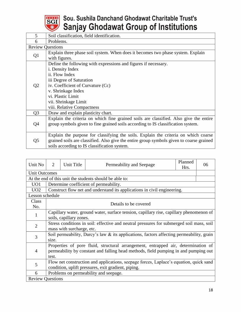
Scheme of Marks
Section Unit No. Title Marks
I 1, 2, 3, 4 Properties of Soil, Permeability and Seepage,
Compaction, Consolidation. 50
II 5, 6, 7, 8 Stress Distribution in Soil, Shear Strength,
Determination of Shear Strength, Earth Pressure 50
Course Unitization
Section
Unit Course
Outcomes No. of Questions in
No. Title CAT-I CAT-II
I 1. Properties of Soil. CO1 1
2. Permeability and Seepage. CO2 2
II 3. Shear Strength of Soil. CO4
1
4. Earth Pressure CO5 2
Unit wise Lesson Plan
Section I
Unit No 1 Unit Title Soil, its properties and basic relationships Planned
Hrs. 06
Unit Outcomes
At the end of this unit the students should be able to:
UO1 Determine index properties of soil.
UO2 Classify the soils based on USCS & ISCS
Lesson schedule
Class
No. Details to be covered
1 Introduction to soil mechanics, field of soil mechanics and its applications, density,
unit weights & unit systems, formation of soil and soil structure.
2 Three phase soil system, water content, density, specific gravity, voids ratio, porosity,
degree of saturation.
3
Functional relationships between:
i. e, G, w & S
ii. γd, G, e & n
iii. γ, G, e & S
iv. γd, G, w &na
4 Grain size distribution, particle size distribution curves, soil consistency.
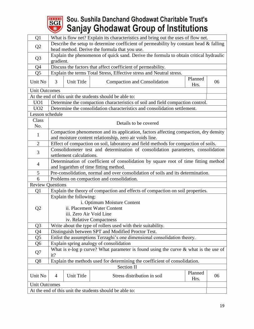
18
5 Soil classification, field identification.
6 Problems.
Review Questions
Q1 Explain three phase soil system. When does it becomes two phase system. Explain
with figures.
Q2
Define the following with expressions and figures if necessary.
i. Density Index
ii. Flow Index
iii Degree of Saturation
iv. Coefficient of Curvature (Cc)
v. Shrinkage Index
vi. Plastic Limit
vii. Shrinkage Limit
viii. Relative Compactness
Q3 Draw and explain plasticity chart.
Q4
Explain the criteria on which fine grained soils are classified. Also give the entire
group symbols given to fine grained soils according to IS classification system.
Q5
Explain the purpose for classifying the soils. Explain the criteria on which coarse
grained soils are classified. Also give the entire group symbols given to coarse grained
soils according to IS classification system.
Unit No 2 Unit Title Permeability and Seepage Planned
Hrs. 06
Unit Outcomes
At the end of this unit the students should be able to:
UO1 Determine coefficient of permeability.
UO2 Construct flow net and understand its applications in civil engineering.
Lesson schedule
Class
No. Details to be covered
1 Capillary water, ground water, surface tension, capillary rise, capillary phenomenon of
soils, capillary zones.
2 Stress conditions in soil: effective and neutral pressures for submerged soil mass, soil
mass with surcharge, etc.
3 Soil permeability, Darcy’s law & its applications, factors affecting permeability, grain
size.
4
Properties of pore fluid, structural arrangement, entrapped air, determination of
permeability by constant and falling head methods, field pumping in and pumping out
test.
5 Flow net construction and applications, seepage forces, Laplace’s equation, quick sand
condition, uplift pressures, exit gradient, piping.
6 Problems on permeability and seepage.
Review Questions
19
Q1 What is flow net? Explain its characteristics and bring out the uses of flow net.
Q2 Describe the setup to determine coefficient of permeability by constant head & falling
head method. Derive the formula that you use.
Q3 Explain the phenomenon of quick sand. Derive the formula to obtain critical hydraulic
gradient.
Q4 Discuss the factors that affect coefficient of permeability.
Q5 Explain the terms Total Stress, Effective stress and Neutral stress.
Unit No 3 Unit Title Compaction and Consolidation Planned
Hrs. 06
Unit Outcomes
At the end of this unit the students should be able to:
UO1 Determine the compaction characteristics of soil and field compaction control.
UO2 Determine the consolidation characteristics and consolidation settlement.
Lesson schedule
Class
No. Details to be covered
1 Compaction phenomenon and its application, factors affecting compaction, dry density
and moisture content relationship, zero air voids line.
2 Effect of compaction on soil, laboratory and field methods for compaction of soils.
3 Consolidometer test and determination of consolidation parameters, consolidation
settlement calculations.
4 Determination of coefficient of consolidation by square root of time fitting method
and logarithm of time fitting method.
5 Pre-consolidation, normal and over consolidation of soils and its determination.
6 Problems on compaction and consolidation.
Review Questions
Q1 Explain the theory of compaction and effects of compaction on soil properties.
Q2
Explain the following:
i. Optimum Moisture Content
ii. Placement Water Content
iii. Zero Air Void Line
iv. Relative Compactness
Q3 Write about the type of rollers used with their suitability.
Q4 Distinguish between SPT and Modified Proctor Test.
Q5 Enlist the assumptions Terzaghi’s one dimensional consolidation theory.
Q6 Explain spring analogy of consolidation
Q7 What is e-log p curve? What parameter is found using the curve & what is the use of
it?
Q8 Explain the methods used for determining the coefficient of consolidation.
Section II
Unit No 4 Unit Title Stress distribution in soil Planned
Hrs. 06
Unit Outcomes
At the end of this unit the students should be able to:

20
UO1 Determine the stresses in soil mass by analytical and graphical methods.
Lesson schedule
Class
No. Details to be covered
1 Stress due to self weight, Boussinesq’s equation for concentrated forces,
Westergaard’s equation, comparison between two.
2 Pressure distribution diagram, pressure bulb and its generation, pressure distribution
on horizontal and vertical plane.
3 Vertical pressure under uniformly loaded circular and rectangular areas, vertical
pressure under line load and strip load.
4 Equivalent pint load method, contact pressure distribution, approximate stress
distribution methods.
5 Newmark’s influence chart and its preparation, Westergaard’s analysis, comparison
between Boussinesq’s and Westergaard’s equation.
6 Problems on Stress Distribution in Soil.
Review Questions
Q1 Write about how to use the Newmak’s chart.
Q2 Sketch contact pressure below rigid foundations on cohesive and cohesionless soils.
Q3 Explain the equivalent point load method for finding the stress below a loaded area.
Q4 Compare Boussinesq’s and Westergaard’s approaches for finding the stress below a
point load.
Q5 Derive Boussinesq’s equation for stress below a point load and show its meaning
through a sketch.
Unit No 5 Unit Title Shear strength Planned
Hrs. 06
Unit Outcomes
At the end of this unit the students should be able to:
UO1 Understand failure theory and draw Mohr’s stress circle.
UO2 Determine shear strength of soil by Coulomb’s equation.
Lesson schedule
Class
No. Details to be covered
1 Introduction of shear strength of soils, theoretical considerations of Mohr’s stress
circle, Mohr – Coulomb failure theory
2 Shear stresses on failure planes, strength envelope, shear strength parameters of soil,
development of failure envelope by total stress and effective stress approach.
3 Determination of shear strength of soil by using laboratory tests.
4 Determination of shear strength of soil for different drainage and consolidation
conditions.
5 Problems on shear strength of soil.
6 Problems on shear strength of soil.
Review Questions
Q1 Explain how the pore pressure is controlled in consolidated undrained shear test.
Q2 Explain how the unconfined compression strength test is used to find the shear

21
strength of soil.
Q3 Draw the strength envelopes for purely cohesive soil, φ – soils & c – φ soils.
Q4 Write a note on Mohr-Coulomb failure theory and how shear stresses on principal
planes are determined.
Q5
Explain with sketch
i. Direct Shear Test
ii. Triaxial Shear Test
iii. Vane Shear Test
Q6 What are the advantages of triaxial compression test?
Q7 Prove the equation for shear strength in Vane shear test; write clearly what the
notations indicate?
Q8 Explain how the unconfined compression strength test is used to find the shear
strength of soil.
Unit No 6 Unit Title Earth pressure Planned
Hrs. 06
Unit Outcomes
At the end of this unit the students should be able to:
UO1 Determine the active, passive and at-rest earth pressures acting of retaining wall.
Lesson schedule
Class
No. Details to be covered
1 Concept of earth pressure and it area of applications in field of civil engineering,
coefficient of active, passive and at-rest earth pressures.
2 Determination of active earth pressure by using Rankine’s theory for cohesive and
cohesionless soils.
3 Determination of passive earth pressure by using Rankine’s theory for cohesive and
cohesionless soils.
4 Rebhann’s graphical method for active earth pressure determination & Coulomb’s trial
wedge method.
5 Culmann’s graphical method for active earth pressure
6 Problems on Earth pressure calculations
Review Questions
Q1 Describe Culmann’s method of finding the active earth pressure with neat sketch.
Q2 Explain Coulomb’s method for finding the active earth pressure with neat sketch.
Q3 Explain Rebhann’s method for finding the active earth pressure with neat sketch.
Q4 What is meant by Active & passive condition of Plastic Equilibrium
Q5 Differentiate between Active, Passive and at rest earth pressures.
Model Question Paper
Course Title : Geotechnical Engineering I
Duration: 3 Hrs. Max. Marks: 100
Instructions:

22
Q 1 from section I and Q5 from section II are compulsory. Answer
any two other questions.
Figures to the right indicate marks.
Assume suitable data if necessary and state the assumptions made
clearly.
Section-I
Marks
1 a For a saturated soil whose w = 40% & G = 2.71, determine saturated
and dry unit weights.
6
b Define:
i. Liquid limit &
ii. Shrinkage limit
4
c What are the uses of flow nets? 5
d Differentiate between compaction and consolidation. 5
2 a The water table in silty-sand deposit, 8 m thick, is at a depth of 3m
below GL. Sand above WT is saturated by capillarity. Γsat of sand is
19.62 kN/m3. Calculate effective pressures at 1m, 3m & 8m depths
below GL. Plot pressure variations for σ, u, σ’.
10
b Briefly explain how sieve analysis test is carried out in the laboratory. 5
3 a What do you understand by “uplift pressure”? 3
b Plastic limit of a soil is 25% and its Ip is 8%. When the dried from its
stat at plastic limit to dry state the volume change is 25% of its volume
at plastic limit. Similarly, the corresponding volume change from its
state at liquid limit to dry state is 34% of its volume at liquid limit.
Determine shrinkage limit, shrinkage ratio & volumetric shrinkage of
the soil.
12
4 a Explain the effects of the following on MDD & OMC with respect to
compaction of soil:
i. Water content
ii. Amount of compaction
6
b An undisturbed sample of clay, 24mm thick consolidated 50% in 20
minutes when tested in the laboratory with double drainage. The clay
layer, from which the sample was obtained, is 4m thick in the field.
i. How much time will it take to consolidate 50% in the field
with double drainage?
ii. If the clay layer in the field had only single drainage,
calculate the time taken to consolidate 50%.
Assume uniform distribution of consolidation pressure.
9
Section-II
Marks
5 a A rectangular footing 2.4m x 2.0m carries audl of 320kN/m2. Find the
vertical pressure at a depth of 4.2m below the center of the footing
using Equivalent point load method.
5
b State any three limitations and any three advantages of direct shear
test.
6
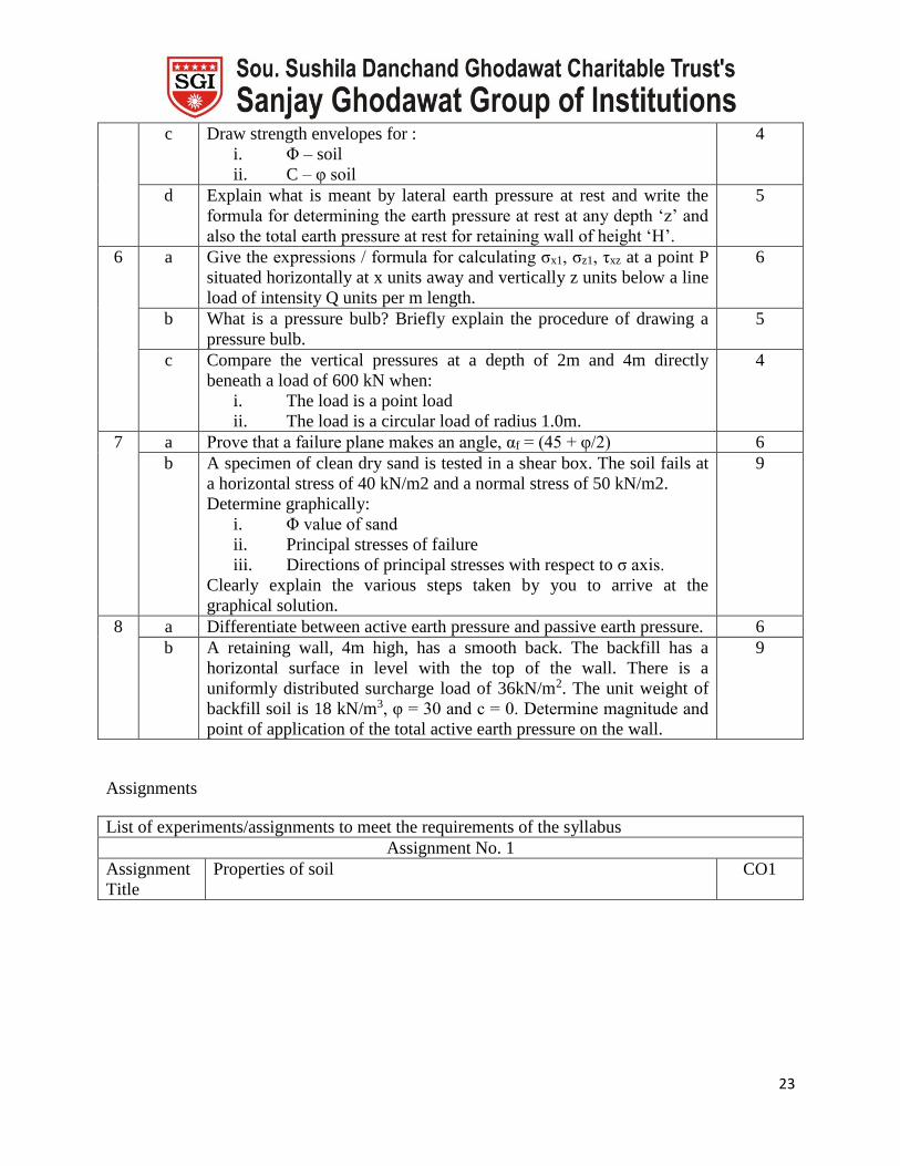
23
c Draw strength envelopes for :
i. Φ – soil
ii. C – φ soil
4
d Explain what is meant by lateral earth pressure at rest and write the
formula for determining the earth pressure at rest at any depth ‘z’ and
also the total earth pressure at rest for retaining wall of height ‘H’.
5
6 a Give the expressions / formula for calculating σx1, σz1, τxz at a point P
situated horizontally at x units away and vertically z units below a line
load of intensity Q units per m length.
6
b What is a pressure bulb? Briefly explain the procedure of drawing a
pressure bulb.
5
c Compare the vertical pressures at a depth of 2m and 4m directly
beneath a load of 600 kN when:
i. The load is a point load
ii. The load is a circular load of radius 1.0m.
4
7 a Prove that a failure plane makes an angle, αf = (45 + φ/2) 6
b A specimen of clean dry sand is tested in a shear box. The soil fails at
a horizontal stress of 40 kN/m2 and a normal stress of 50 kN/m2.
Determine graphically:
i. Φ value of sand
ii. Principal stresses of failure
iii. Directions of principal stresses with respect to σ axis.
Clearly explain the various steps taken by you to arrive at the
graphical solution.
9
8 a Differentiate between active earth pressure and passive earth pressure. 6
b A retaining wall, 4m high, has a smooth back. The backfill has a
horizontal surface in level with the top of the wall. There is a
uniformly distributed surcharge load of 36kN/m2. The unit weight of
backfill soil is 18 kN/m3, φ = 30 and c = 0. Determine magnitude and
point of application of the total active earth pressure on the wall.
9
Assignments
List of experiments/assignments to meet the requirements of the syllabus
Assignment No. 1
Assignment
Title
Properties of soil CO1
24
All Batches Q.1. A soil sample has a porosity of 40%. The specific gravity of soil is 2.7.
Calculate (a) Voids ratio, (b) dry density, (c) unit weight of soil if soil is 50%
saturated & (d) unit weight of soil if the soil is completely saturated.
Q.2. If Cu / Cc = 4 & Cu x Cc = 9, find Cu, Cc, D30, D60. Assume D10 = 0.1mm.
Q.3. Plastic limit, liquid limit and natural water content of soil sample is 40%,
65% & 48% resp. Find plasticity index, liquidity index and consistency index.
Q.4. Prove that maximum dry density of soil is 1.4 times the minimum for the
value of G=2.6, emin=0.4 &emax=1.
Q.5.For a saturated soil whose w = 40% & G = 2.71, determine saturated and dry
unit weights.
Assignment No. 2
Assignment
Title
Permeability and seepage CO2
All Batches Q.1. A 3.0m thick sandy stratum exists below a clay layer 4.0m thick. The clay
layer is at the bed of a lake with standing water height of 4.0m. Saturated density
of clay and sand is 19.3 kN/m3& 21.8 kN/m3 resp. Compute total stress, pore
pressure and effective stress at mid height of the sandy stratum.
Q.2. The co-efficient of permeability of soil sample is found to be 1 x 10⁻³ cm/sec
and the voids ratio of 0.4. Estimate the permeability of sand for a voids ratio of
0.6.
Q.3. A constant head permeability test was conducted on a cylindrical specimen
of 10cm diameter and 15cm height. 160cm3 of water was collected in 1.75
minutes under a head of 30cm. Compute coefficient of permeability, ‘k’ in m/year
and velocity of flow in m/sec. If porosity of the sample is 40% calculate the
seepage velocity.
Q.4.The water table in silty-sand deposit, 8 m thick, is at a depth of 3m below
GL. Sand above WT is saturated by capillarity. Γsat of sand is 19.62 kN/m3.
Calculate effective pressures at 1m, 3m & 8m depths below GL. Plot pressure
variations for σ, u, and σ’.
Assignment No. 3
Assignment
Title
Compaction CO3
All Batches Q.1. In standard proctor compaction test, the following results are obtained:
Optimum moisture content = 20%
Maximum dry density = 1.9g/cm3
Determine the porosity of compacted soil corresponding to OMC & MDD.
Also determine dry density at 100% saturation. Take G = 2.68.
Q.2. The following observations were made in a Standard Proctor Test, with
mould volume of 945c.c. and soil specific gravity of G = 2.67
Trial No. 1 2 3 4 5 6
Mass of wet
soil (kg) 1.7 1.89 2.03 1.99 1.96 1.92
Water
content 7.7 11.5 14.6 17.5 19.7 21.2

25
Determine maximum dry density and optimum moisture content. Also plot ZAV
line.
Q.3. The in-situ unit weight of an embankment, compacted at a water content of
12%, was determined by a core cutter. The empty weight of the core cutter was
1286gm. Core cutter filled with soil weighed 3195 gm. Volume of the core cutter
was 1000 cm3. Determine the following:
i. bulk unit weight
ii. dry unit weight and
iii. degree of saturation.
If the embankment becomes fully saturated, find its water content and saturated
unit weight. Assume G = 2.7.
Assignment No. 4
Assignment
Title
Consolidation CO4
All Batches Q.1. A saturated layer of 9m thick clay overlies rock strata & is cover on top by a
previous overburden .determine the time required for clay layer to reach half of
its ultimate settlement. takeCv = 5x10⁻⁴ cm2/sec (Tv)50 =0.196.
Q.2. The table summarizes the results of an oedometer test on a sample.
Pressure
kN/m2
0 13 27 54 108 214 480 960 1500
Dial
reading
(cm)
0.0 0.0 0.004 0.16 0.044 0.104 0.218 0.34 0.42
Initial height of sample = Hi=2.5cm
Height of solid particles = Hs=1.25cm.
Plot the curve & determine compression index &precosolidation pressure.
Q.3. A clay layer, 8m thick is subjected to a pressure of 70kN/m2. If the layer has
a double drainage and undergoes 50% consolidation (Tv=0.196) in one year.
Determine the coefficient of consolidation. If coefficient of permeability is
0.04m/year, determine the settlement in one year. Use Yw = 9.81 kN/m3.
Q.4. In a consolidation test, the void ratio of the specimen which was 1.068 under
the effective pressure of 214 kN/m2, changed to 0.994 when the pressure was
increased to 429 kN/m2. Calculate the coefficient of compressibility, compression
index and coefficient of volume compressibility.
Q.5. A saturated soil has Cc = 0.28, the void ratio at a stress of 12kN/m2 is 2.05
and its permeability is 35 x 10-7 mm/s. Compute:
i. change in void ratio if the stress is increased to 21.6 kN/m2.
ii. the settlement in (i) above if the soil stratum is 6m thick.
Q.6. A saturated clay layer, 5m thick, lies under a newly constructed building.
The effective pressure due to overlying strata on clay layer is 300 kN/m2. The
new construction increases the effective pressure by 120 kN/m2. If compression
index (Cc) of the clay is 0.45, compute settlement in clay layer because of the
new building. Given, w = 43% & G = 2.7.
Assignment No. 5
Assignment Stress distribution in soil CO5

26
Title
All Batches Q.1. On either side of point P the loads 600 kN and 1000 kN are located at 2.0m
and 3.0m respectively. Find the total stress developed 2.0m below the point P
using Boussinesq’s equation.
Q.2. On ground surface a rectangular plate 1m x 1.5m is loaded with intensity of
800 kN/sqm. Find the stress 1.2m below the centre of the plate. Compare this if
an approximate method of 1V:2H method is adopted.
Q.3. A rectangular area 4m x 2m is uniformly loaded with a load intensity 10t/m2
at the ground surface. Calculate the vertical pressure at a point 3m below one of
its corners. By equivalent – area method, (making four parts).
Q.4. A point load of 1000 kN acts on the ground surface. Find and show the
variation of vertical stress on a horizontal plane at a depth of 5m below the
surface, for radial distances of 0, 1, 2 and 4m.
Q.5. A point load of 1000 kN acts on the ground surface. Find and show the
variation of vertical stress on a vertical plane at a radial distance of 1m and at
depths of 0.5, 1, 2 and 6m.
Q.6. Find the intensity of vertical pressure and horizontal shear stress at a point
4m directly beneath a 20 kN point load acting at ground surface. What will be the
vertical pressure and horizontal shear stress at a point 2m horizontally away from
the axis of loading at the same depth of 4m.
Q.7.A rectangular footing 2.4m x 2.0m carries audl of 320kN/m2. Find the
vertical pressure at a depth of 4.2m below the center of the footing using
Equivalent point load method.
Assignment No. 6
Assignment
Title
Shear Strength CO6
All Batches Q.1. A cylindrical specimen of sand was tested in a triaxial test apparatus. Failure
occurred under a cell pressure of 120 kN/sqm, at a deviator stress of 400 kN/sqm.
Determine :
i. Angle of internal friction
ii. Angle of failure plane wrt horizontal
iii. Normal and shear stresses on failure plane.
Q.2. Following are the results of four drained shear tests with size of specimen =
6cm x 6cm, height of specimen is 3cm.
Test No. Normal load (N) Shear Load (N)
1 200 155
2 300 230
3 400 310
4 500 385
Draw the graph for the shear stress against normal stress and determine shear
strength parameters.
Q.3. A consolidated undrained test was conducted on a clay sample and the
following results were obtained; find shear strength parameters with respect to
effective stresses.
Cell pressure (kN/sqm) 200 400 600

27
Deviator stress at failure (kN/sqm) 118 240 352
Pore water pressure at failure (kN/sqm) 110 220 320
Q.4. Clean dry sand samples were tested in a large shear box 25cm x 25cm and
the following results were obtained. Determine shear strength parameters.
Normal stress at failure (kN) 150 250
Shear stress at failure (kN) 110 120
If the sample of the same soil is tested in a triaxial test with cell pressure of 150
kN/sqm,at what deviator stress would it fail?
Q.5. A cylindrical specimen of 38mm diameter and 76mm length was tested
under unconfined compression strength test. The load at failure was 55 N and
axial deformation was 10mm. Find shear strength parameters if the failure plane
makes an angle of 560 with horizontal.
Q.6. A specimen of fine dry sand when subjected to a triaxial compression test,
failed at a deviator stress of 400 kN/m2. Compute the lateral pressure to which the
specimen would have been subjected to. Take Ø = 440.
Q.7. A shear box test conducted on a soil sample gives following observations:
Normal Load (N) 360 720 1080 1440
Shear Load Proving Dial Readings (Divs.) 13 19 26 32
If the shear box is 60mm square and proving ring constant is 20 N per division,
find out the shear strength parameters (C and Ø) of the soil in kN/m2 and degrees
respectively.
Q.8. Two triaxial tests were conducted on a material. In the first test failure
occurred at σd = 750 kN/m2& a cell pressure of 250 kN/m2. In the other test cell
pressure was 400 kN/m2 and failure occurred at total pressure of 1600 kN/m2.
Determine the shear parameters c & φ.
Q.9. A CU test was conducted on a sample with cell pressure = 100 kN/m2&σd =
60 kN/m2. The soil has c = 0 kN/m2, φ = 300 (w.r.t. effective stresses) and cu = 0
kN/m2&φu = 13.30 (w.r.t. total stresses). What was the pore pressure at failure?
Q.10. A specimen of clean dry sand is tested in a shear box. The soil fails at a
horizontal stress of 40 kN/m2 and a normal stress of 50 kN/m2.
Determine graphically:
i. Φ value of sand
ii. Principal stresses of failure
iii. Directions of principal stresses with respect to σ axis.
Clearly explain the various steps taken by you to arrive at the graphical solution.
Assignment No. 7
Assignment
Title
Earth pressure CO7
All Batches Q.1. A backfill consists of soil of unit weight of 16.5 kN/m3, Ø = 260 with
cohesion of 10 kN/m2. The fill has on top surface a uniform surcharge of intensity
16 kN/m2. Determine the earth pressure force per unit length after the crack has
developed. Show its position from the base.
Q.2. A backfill consists of soil of unit weight of 15 kN/m3, Ø = 260 with cohesion
of 8 kN/m2. The fill has on top surface a uniform surcharge of intensity 10 kN/m2.
28
Determine the earth pressure force per unit length and its position from the
bottom.
Q.3. A smooth backed vertical wall is 6.3m high and retains a soil with a bulk
unit weight of 18 kN/m3 and Ø = 180. The top of the soil is level with the top of
the wall and is horizontal. If the soil surface carries a uniformly distributed load
of 45 kN/m2, determine the total active thrust on the wall per linear metre of the
wall and its point of application.
Q.4. A smooth vertical wall 5m high retaqins a soil with C = 2.5 N/cm2, Ø = 300
and unit weight of 18 kN/m3. Show the Rankine passive pressure distribution and
determine the magnitude and point of application of the passive resistance.
Q.5. A retaining wall 9m high retains a cohesionless soil, with an angle of internal
friction 330. The surface is level with the top of the wall. The unit weight of the
top 3m of the fill is 21 kN/m3 and the rest is 27 kN/m3. Find the magnitude and
point of application of the resultant active thrust.
Q.6. A rigid retaining wall, 6m high, is restricted from yielding. The backfill
consists of cohesionless soil whose φ = 260 and γ = 19 kN/m3. Compute :
i) Earth pressure at the base of the wall.
ii) Total earth pressure and its point of application.
Q.7. Compute the intensities of active and passive earth pressure at a depth of 8 m
in a cohesionless sand with φ = 300 and γdry = 18 kN/m3. What will be the active
and passive earth pressures if WT rises to the GL ? Take γsat = 22 kN/m3.
Q.8.A retaining wall, 4m high, has a smooth back. The backfill has a horizontal
surface in level with the top of the wall. There is a uniformly distributed
surcharge load of 36kN/m2. The unit weight of backfill soil is 18 kN/m3, φ = 30
and c = 0. Determine magnitude and point of application of the total active earth
pressure on the wall.
Lab Plan
Experiment
No Experiment Title CO
1 Determination of water content by oven drying. CO1
2 Specific gravity determination by pycnometer / density bottle. CO1
3 Particle size distribution-Dry Mechanical sieve analysis CO1
4 Determination of consistency limits (minimum 2- LL, PL, SL) CO1
5 Field density test by core cutter CO1
6 Field density test by sand replacement method CO1
7 Determination of co-efficient of permeability by variable head method. CO2
8 Standard proctor test/ Modified proctor test. CO3
9 Direct shear test – CD CO4
Laboratory demonstrations (Any 2)
29
Experiment
No Experiment Title CO
1 Determination of co-efficient of permeability by constant head CO2
2 Particle size distribution-Sedimentation analysis (hydrometer) CO1
3 Unconfined Compression Test CO4
4 Triaxial shear test. CO4
5 One dimensional consolidation test. CO3
Course Plan
Course Water Resource Engineering - I Course Code 101
Examination
Scheme
Theory Term Work POE Total
Max. Marks 100 50 150
Contact
Hours/ week
3 2 -- 5
Prepared by Ms. A. S. Manjarekar Date 15/6/2015
Prerequisites This course requires the student to know about the basic concepts regarding
hydrologic cycle with evaporation , infiltration & runoff, groundwater
hydrology with open well & tube well design, irrigation
Course Outcomes
At the end of the course the students should be able to:
CO1 Apply the knowledge of estimation of hydrometeorological parameters
CO2 Design of hydrograph and measurement of discharge
CO3 To design of tube well and open well
CO4 To develop the methods of consumptive use of surface water and groundwater
and minor irrigation works
Mapping of COs with POs
POs
COs
a b c d E F G h i j k L
CO1 √ √ √ √ √
CO2 √ √ √ √ √
CO3 √ √ √ √
Co4 √ √ √ √
Course Contents

30
Unit No. Title No. of
Hours
Section I
1. Introduction of Hydrology: Definition, Importance and scope of
hydrology, the hydrologic cycle,
Precipitation: Forms and types of precipitation, Methods of
measurement, Graphical representation of rainfall - Mass rainfall curves,
Hyetograph, Determination of average precipitation over the catchment.
Evaporation: Proccess, factors affecting, measurement, and control of
evaporation, Infiltration: Process, Factors affecting and measurement of
Infiltration
08
2. Runoff: Factors affecting runoff, Determination of annual runoff,
Rainfall runoff relationship
Hydrograph: Storm hydrograph, Base flow and Separation of base flow,
direct runoff hydrograph, Unit hydrograph – theory – assumptions and
limitations, Derivation and use of unit hydrograph, S-curve hydrograph.
06
3. Stream gauging: Selection of site, discharge measurement by Area
velocity method, slope Area method
Floods: Estimation of peak flow-- empirical equations, rational method,
Importance of --Design flood, standard project flood, maximum
probable flood, Introduction to flood frequency analysis.
06,
Section II
4
Ground water hydrology: Occurrence, distribution and classification of
ground water, Darcy’s law, Acquifer parameters— Permeability,
specific yield, specific retention, porosity, storage coefficient,
Transmissibility,Hydraulics of well under steady flow conditions in
confined and unconfined aquifers, Specific capacity of well,
Recuperation Test, constructional features of Tube wells and Open
wells .
06
5 Introduction to irrigation: Definition and necessity of irrigation, ill-
effects of irrigation, surface, sub-surface, sprinkler irrigation, Water
logging and land drainage,
Water requirement of crops:
Principal crops and crop seasons, cropping pattern and crop rotation,
Classes and availability of soil water, depth and frequency of irrigation,
Duty, delta, base period and their relationship, factors affecting duty,
methods of improving duty, Assessment and efficiency of irrigation
water. Gross command area, culturable command area and command
area calculations based on crop water requirement.
Estimation of evapo-transpiration by blaney-criddle method and penman
method,
08
7 Minor Irrigation works : General layout, main components and
functioning of –
1. Percolation tanks, 2. K.T.Weir, 3. Bandhara irrigation 4.
06
31
Lift irrigation
Watershed Management: Need and importance of watershed
management, Soil conservation measures, Techniques of Rainwater and
groundwater harvesting.
Reference Books:
Sr. No. Title of Book Author Publisher/Edition Topics
1 Irrigation Engg. S. K. Garg Khanna
publications
6,7
2 Irrigation and water resource
engineering
B.C. Punmia, Jain LaxmiPubilcations ALL
3 Irrigation and water resource
engineering
K. R. Arora standard
publications
ALL
Scheme of Marks
Section Unit No. Title Marks
I 1,2,3 Introduction Of Hydrology and Evaporation Runoff &
Infiltration, Hydrograph, Stream gauging
50
II 4,5,6 Groundwater hydrology,soil water relationship, minor
irrigation works
50
Course Unitization
Section
Unit Course Outcomes No. of Questions in
No. Title CAT-I CAT-II
I 1 Introduction Of
Hydrology, infiltration.
Explain hydrologic
cycle and types of
precipitation.
3 -
2 Runoff & hydrograph Explain runoff and its
methods of
measurement.
3
II 3 Stream gauging Explain different
methods of
measurement of
discharge & maximum
flood..
- 3
4 Groundwater
hydrology
Explain groundwater
hydrology & design of
3
32
open well and tube well.
Unit wise Lesson Plan
Section I
Unit No 1 Unit Title INTRODUCTION TO HYDROLOGY,
INFILTRATION AND EVAPORATION
Planned
Hrs.
8
Unit Outcomes
At the end of this unit the students should be able to:
UO1 Explain hydrologic parameters and infiltration and evaporation CO1
Lesson schedule
Class
No.
Details to be covered
1 Introduction to hydrologic cycle, weather and its precipitation potential
2 Forms & types of precipitation
3 Methods of measurement of precipitation
4 Double mass analysis, hyetograph and mass rainfall curve
5 Estimation of missing rainfall data and average precipitation over the catchment
6 Evaporation, measurement of evaporation
7 Factors affecting evaporation as well as infiltration
8 Measurement of infiltration
Review Questions
Q1 Explain hydrologic cycle with sketch. CO1
Q2 Define hydrology. enlist the engg. Activities where hydrological studies
are essential.
CO1
Q3 Describe various types of precipitation CO1
Q4 Write a note on – a) cloud seeding
b) raingauge density
c) network of raingauge
d) laps rate & its type
e) humidity & its type
f) radar measurement
CO1
Q5 Enlist & explain types of rain gauge with neat sketch. CO1
Q6 What are the various selection criteria for raingaugestation. CO1
Q7 How will you control evaporation from reservoir CO1
Q8 What are the different methods of evaporation with neat sketch. CO1
Q9 Define evaporation. Explain factors affecting evaporation CO1
Q10 Define infiltration, infiltration capacity and infiltration rate CO1
Q11 Enlist and explain factors affecting infiltration. CO1
Q12 State and explain infiltration capacity curve CO1
Q13 Explain the methods of measurement of infiltration CO1
Unit No 2 Unit Title RUNOFF AND HYDROGRPH Planned
Hrs.
06
33
Unit Outcomes
At the end of this unit the students should be able to:
UO2 Explain various components of hydrograph,Draw storm hydrograph ,direct
runoff hydrograph, unit hydrograph and S curve hydrograph and methods of
measurement and runoff and its methods of measurement
CO1
Lesson schedule
Class
No.
Details to be covered
9 Runoff, factors affecting runoff
10 Methods for calculation of runoff
11 Storm hydrograph and its components
12 Direct runoff hydrograph, base flow and separation of base flow
13 Unit hydrograph theory ,assumption and limitation
14 UH derivation ,S-curve hydrograph
Review Questions
Q1 Define hydrograph. Explain various components of it CO1
Q2 What is mean by base flow and negative base flow? CO1
Q3 What are the various methods of estimation of base flow? CO1
Q4 What is UH? Give limitations assumption and use of unit hydrograph? CO1
Q5 What is the procedure of construction of unit hydrograph?- CO1
Q6 Define runoff. What are the various factors affecting the runoff., CO1
Q7 Write various methods of estimating runoff CO1
Unit No 3 Unit Title STREAM GAUGING Planned
Hrs.
6
Unit Outcomes
At the end of this unit the students should be able to:
UO3 Explain various methods of measurement of discharge and peak flood CO2
Lesson schedule
Class
No.
Details to be covered
15 Selection of site for stream gauging
16 Area velocity method
17 Slope area and other methods
18 Flood hydrograph and types
19 Methods of measurement of peak flood
20 Methods of measurement of peak flood
Review Questions
Q1 Define stream gauging. Give site selection criteria for it. CO2
Q2 Write note on current meter CO2
Q3 Describe briefly the different methods to estimate the magnitude of peak
flood.
CO2
Q4 Explain stage discharge relationship or stage rating curve CO2
Write a note on – a) design flood CO2
34
b) standard project flood
c) probable maximum flood
d) recurrence period
State and explain various methods of stream gauging. CO2
SECTION II
Unit No 4 GROUNDWATER HYDROLOGY Planned
Hrs.
06
UO4 Explain hydraulics of well under steady flow in confined & unconfined
aquifer and Design open well & tube well
CO3
Class
No.
21 Occurrence & distribution of groundwater, specific yield of aquifer
22 Movement of groundwater, Darcy law of permeability
23 Hydraulics of well under steady flow in confined aquifer
24 Hydraulics of well under steady flow in an unconfined aquifer
25 open well- design and construction
26 tube well- design and construction
Review Questions
Q1 Define groundwater hydrology.explain types of aquifer with neat sketch. CO3
Q2 Explain the darcy law for ground water movement and its range of validity CO3
Q3 Write note on ovccurence of groundwater table. CO3
Q4 Derive the expression for discharge for steady flow to the well in an
unconfined aquifer. Explain in terms of radius of influence.
CO3
Q5 Derive the expression for discharge for steady flow to the well in an
confined aquifer
CO3
Q6 Differentiate between tube well and open well CO3
Q7 Write the procedure to construct the open well CO3
Q8 Write the procedure to construct the TUBE well CO3
Unit No 5 Unit Title IRRIGATION AND SOIL WATER
RELATIONSHIP
Planned
Hrs.
8
Unit Outcomes
At the end of this unit the students should be able to:
UO5 Explain different types of irrigation & various methods of application of
water to soil
CO4
Lesson schedule
Class
No.
Details to be covered
27 Introduction to irrigation and its necessity and Types of irrigation
28 Methods of application of water to soil
29 Water logging and land drainage
30 Classes and availability of soil water, principal crop and crop seasons
31 Cropping pattern , crop rotation, command area calculation
35
32 Duty, delta, factors affecting duty
33 Methods of improving duty, consumptive use of water
34 Estimation of evapotranspiration , efficiency of irrigation
Review Questions
Q1 define irrigation and its necessity. CO4
Q2 Explain the various types of irrigation systems CO4
Q3 Explain various methods of application of water to soil CO4
Q4 Write note on Water logging and land drainage CO4
Q5 Define the soil water. Give the classification of it. CO4
Q6 Explain the various crop seasons in india. CO4
Q7 Write note on - a) frequency of irrigation
b) cropping pattern
c) crop rotation
d) consumptive use of water
CO4
Q8 What is mean by duty, delta & base period. Derive the relation between
them.
CO4
Q9 What are the various factors affecting the duty. CO4
Q10 What is mean by efficiency of irrigation & various types of it. CO4
Q11 State & explain classification of crop. CO4
Q12 What are the methods of calculating consumptive use of water. CO4
Unit No 6 Unit Title MINOR IRRIGATION WORKS Planned
Hrs.
06
Unit Outcomes
At the end of this unit the students should be able to:
UO8 Draw layout of percolation tank, k,t,weirs and lift irrigation scheme &
explain watershed management and rainwater harvesting
CO4
Lesson schedule
Class
No.
Details to be covered
35 General layout of percolation tank, K.T. weir
36 Lift irrigation & its main components
37 Rainwater harvesting and its methods
38 Methods of groundwater harvesting
39 watershed management
40 soil conservation techniques
Review Questions
Q1 Explain with layout of percolation tank & its design consideration. CO4
Q2 Write a note on ground water recharge techniques. CO4
Q3 What do you understand by rain water harvesting. CO4
Q4 Briefly explain various techniques used for rain water harvesting. CO4
Q5 Write a note on percolation tank with following –
a) Site selection
b) Construction detail
c) Advantages & disadvantages
CO4
36
Q6 What do you understand by watershed management. Explain in details
different activity performed in water shed management programme.
CO4
Q7 Write a note on soil conservation techniques. CO4
Q8 Explain with neat sketch KT weir. CO4
Q9 Explain with neat sketch general layout of various components of lift
irrigation scheme.
CO4
Model Question Paper
Course Title
:
WATER RESOURCE ENGG. I
Duration 3 Hrs Max.
Marks:
100
Section-I
Marks
1 a Explain hydrologic cycle with sketch. 8
b Enlist & explain any two types of rain gauge with neat sketch. 8
2 a How will you control evaporation from reservoir 6
b State and explain infiltration capacity curve 10
3 a What is UH? Give limitations assumption and use of unit hydrograph? 9
b Define hydrograph. Explain various components of it. What is S-curve
hydrograph?
9
4 a Explain stage discharge relationship or stage rating curve 6
b Write note on current meter 6
c Define stream gauging. Give site selection criteria for it. 6
5 a Write a note on – a) network of raingauge
b) standard project flood
c) methods of base flow seperation
d) radar measurement
Section-II
Marks
6 a Derive the expression for discharge for steady flow to the well in an
unconfined aquifer. Explain in terms of radius of influence.
8
b Differentiate between tube well and open well 8
7 a Explain various methods of application of water to soil 8
b Write note on Water logging and land drainage 8
8 a What is mean by duty, delta & base period. Derive the relation
between them.
4
b Rainwater harvesting and its methods 4

37
c State & explain classification of crop. 4
d Explain with neat sketch KT weir. 4
9 b Write note on - a) frequency of irrigation
b) lift irrigation
c) necessity of irrigation
18
Assignments
Assignments
Assignment no. Assignment Title CO1 to CO4
1 Determination of average annual rainfall
2 Determination of abstraction losses – phi index calculation
3 To develop SH, UH, DRH and S hydrograph
4 Stream flow measurements – Area velocity and slope-area method
5 Yield calculations of open well and tube well.
6 Determination of Crop water requirement using consumptive use formulae
7 Layout of lift irrigation, K.T.Weir and percolation tank
Course Plan
Course Transportation engineering Course Code 47904
Examination
Scheme Theory Term Work POE Total
Max. Marks 100 25 25 150
Contact
Hours/ week 3 2 -- 5
Prepared by Kore S.B, Patil Date 15-06-2015

38
At the end of the course the students should be able to:
CO1 Design features such as super-elevation sight distance section of road in cutting and filling
CO2 Design flexible and rigid pavement as per IRC.
CO3 Carryout quality control for WBM, BBM, and concrete pavements.
CO4 Design and plan airport, runways terminals buildings, hangers and aprons.
CO5 Plan different methods of tunneling in soft and hard rocks
CO6 Plan and layout for docks and ports.
Mapping of COs with POs
POs
COs
a b c d e f g h i j k l
CO1 √ √ √ √
CO2 √ √ √ √
CO3 √ √ √
CO4 √ √ √
CO5 √ √
CO6 √ √
Course Contents
Unit No. Title No. of
Hours
Section I
1.
Highway planning-Classification of roads, brief history of road
development in India, present status of roads in India. NHAI,
NHDP, PMGSY, MSRDC.
Geometric design of highways-Terrain classification, design speed,
07

39
vehicular characteristics, highway cross-section elements Sight
distance: introduction to sight distance, reaction time, analysis of
safe sight distance, analysis of overtaking sight distance,
intersection sight distance. Design of horizontal alignment:
horizontal curves, design of super elevation and its provision,
radius at horizontal curves, widening of pavements at horizontal
curves, analysis of transition curves. Design of vertical alignment:
different types of gradients, grade compensation on curves,
analysis of vertical curves, summit curves, valley curves.
2.
Pavement materials- Stone aggregates: desirable properties, tests,
requirements of aggregates for different types of pavements.
Bituminous materials: types, tests on bitumen, desirable properties,
selection of grade of bitumen. Bituminous mix design: principle,
methods, modified binders.
Design of pavements-Types of pavements, functions of pavement
components, pavement design factors, design wheel load,
equivalent single wheel load, repetition of loads, equivalent wheel
load factors, strength characteristics of pavement materials,
climatic variation; design steps of flexible highway pavement as
per IRC 37-2001 and problems based on CBR method, Design of
rigid pavement as per IRC 58-2002, Stresses in rigid highway
pavements, , Joints in rigid pavements: transverse joints,
longitudinal joints, fillers and sealers.
06
3.
Traffic engineering- traffic characteristics, traffic studies.
Highway construction- Types of roads: WBM, BBM, SDBC,
DLC& PQC.Highway drainage- Necessity, surface draining, sub
surface drainag
06
Section II
4.
Airport Engineering- introduction, terminology, components of
Aircraft, aircraft characteristics.
Airport planning: airport surveys, site selection, obstructions.
Runways: orientation, wind rose, basic runway length, geometric
design, airport capacity, runway patterns.
Taxiways, terminal buildings.
08
6.
Docks and Harbour Engineering : introduction, planning and layout
of ports, classification of ports and harbours,, site selection, break
water, jetties
05

40
7.
Tunnel Engineering: Introduction to tunnelling
Tunneling in hard rock, and soft material, shield method, tunnel
lining, safety measures, ventilation, lighting and drainage
tunnelling.
05
Reference Books:
Sr. No. Title of Book Author Publisher/Edition Topics
01 Highway Engineering Khanna S.K. and
C.E.G. Justo
NemChand&
Bros., Roorkee.
1,2,3,
02 Principles of Transportation
Engineering
ParthaChakroborty
and Animesh Das
Prentice-Hall
India, New Delhi
1,2,3,
03 Pavement Analysis and Design Yang H. Huang Prentice-Hall 2
04 Airport Planningand Design Khanna S.K.,
Arora M.G. and
Jain S.S.
Prentice-Hall
India, New Delhi
4
05 Dock and Harbor Engineering Oza Chartor pub.
house
5
06 Dock, Harbor and Tunnel
Engineering
Shrinivasan Chartor pub.
house
5,6
07 IRC: 76-1979 – Tentative
Guidelines for Structural
Strength Evaluation of Rigid
Airfield Pavement
Indian Roads
Congress
IRC, New Delhi. 2,4
08 IRC: 85-1983 – Code of
Practice for Accelerated
Strength Testing and Evaluation
of Concrete Road and Air field
Constructions
Indian Roads
Congress
IRC, New Delhi. 2,4
09 IRC: 58-2002 (Second
Revision) – Guidelines for the
Indian Roads
Congress
IRC, New Delhi. 2

41
Design of Rigid Pavements for
Highways
10 IRC: 37-2001 – Guidelines for
the Design of Flexible
Pavements for Highways
Indian Roads
Congress
IRC, New Delhi. 2
Scheme of Marks
Section Unit No. Title Marks
I 1 Unit 1: Introduction to Highway Engineering and
Highway Geometric Design
16/18
2 Unit 2: Pavement Design 16/18
3 Unit 3: Traffic Engineeringand Highway
Construction and Highway Drainage
16/18
II 4 Unit 4: Airport Engineering 16/18
5 Unit 5: Dock And Harbour Engineering 16/18
6 Unit 6: Tunnel Engineering 16/18
Course Unitization
Section
Unit Course
Outcomes
No. of Questions in
No. Title CAT-I CAT-II
I
1
Unit 1: Introduction to
Highway Engineering and
Highway Geometric Design
CO1 Q1,2,3
2 Unit 2: Pavement Design CO2 Q1,2,3
3
Unit 3 Traffic
Engineeringand Highway
Construction and Highway
Drainage
CO3 Q1,2,3

42
II
4 Unit 4: Airport Engineering CO5 Q1,2,3
5 Unit 5: Tunnel Engineering CO6 Q1,2,3
6 Unit 6: Dock And Harbour
Engineering
CO7
Unit wise Lesson Plan
Section I
Unit No 1 Unit
Title
Introduction to Highway Engineering
and Highway Geometric Design
Planned
Hrs.
07
Unit Outcomes
At the end of this unit the students should be able to:
UO1 To know various government policies regarding development of
roads.
CO1
UO2 To understand concepts and methods of Highway Finance CO1
UO3 To understand basics of Highway Geometric Design. CO1
Lesson schedule
Class No. Details to be covered
1 Introduction to Scope of highway engineering., Road development plans,
Recent developments – NHAI,NHDP,PMGSY,MSRDC
2 Highway Geometric Design: Terrain classification, Highway Alignment-
Definition, requirements, factors controlling alignment, of hill roads
3 Highway Geometric Design: Cross-sectional elements, sight distances
4 Highway Geometric Design: Horizontal alignment – super elevation, widening
of pavement on horizontal curve
5 Highway Geometric Design: Vertical alignment –gradient, vertical curves
6 Highway Geometric Design: Design Problems
43
7 Highway finance –BOT, BOOT, Annuity, PPP, DBFO.
Review Questions
Q1 Define objects of Highway Planning and explain empirical methods
of estimation of total unit cost of highway transportation.
CO1
Q2 How terrains are classified and write a note on factors affecting
controlling alignment of hilly roads.
CO1
Q3 What are cross sectional elements of Highway? Derive the formula
for overtaking sight distance and safe sight distance.
CO1
Q4 What is superelevation? Explain with neat sketch how a vehicle
negotiating horizontal curve is prevented from skidding or
overtopping.
CO1
Unit No 2 Unit Title Pavement Design Planned Hrs. 06
Unit Outcomes
At the end of this unit the students should be able to:
UO1 To design flexible pavement as per IRC 37:2001 CO2
UO2 To design rigid pavement as per IRC 58:2002 CO2
Lesson schedule
Class No. Details to be covered
1 Pavement Design: Pavement types, components, functions, design factors
2 Design of flexible pavements, CBR Method
3 Design of flexible pavements: IRC: 37-2001.
4 Design of rigid pavement: Westergaard’s analysis of wheel load stress,
temperature stresses.
5 Types of joints and their functions
6 Design of rigid pavements: IRC: 58-2002 method of design.
Q1 Explain factors affecting design of flexible pavement. CO2
Q2 What are the types of road pavement? Explain components of rigid CO2

44
pavement.
Q3 Explain the factors which affect design of rigid pavement. CO2
Q4 Write design procedure as per IRC 37 to design flexible pavement CO2
Q5 Write design procedure as per IRC 58 to design rigid pavement CO2
Unit No 3 Unit Title Traffic Engineeringand
Highway Construction
and Highway Drainage
Planned Hrs. 06
Unit Outcomes
At the end of this unit the students should be able to:
UO1 To understand principles of highway construction procedure for
various layers of pavement as per specifications.
CO3
UO2 To understand importance highway drainage and means to achieve
good highway drainage.
CO3
UO3 To understand concepts of traffic characteristics, traffic studies and
analysis.
CO3
UO4 To learn various traffic control devices used for controlling the
traffic.
CO3
Lesson schedule
Class No. Details to be covered
1 Highway materials, WMM roads,;
2 Bituminous roads-BC, SDBC, DBM
3 Concrete roads-DLC,PQC
4 Stabilizedroad, MOST specifications.
5 Necessity of highway drainage, surface and subsurface drainage
6 Maintenance and repairs of highway drainage.
7 Traffic Engineering: Traffic characteristics, Traffic studies and
analysis, Road marking, Traffic sign
45
Review Questions
Q1 What is meant by DLC and PQC CO3
Q2 Write short note on MoST specifications for BC, SDBC, DBM CO3
Q3 What are the materials used for construction of highway? CO3
Q4 What is meant by stabilized roads? CO3
Q5 Explain necessity of providing highway drainage. Write short note
on surface and subsurface drainage
CO3
Q6 Write short note on traffic control devices. CO3
Q7 Explain parameters of traffic. CO3
Q8 What are the types of traffic signals? CO3
Q9 Explain importance of traffic signals and road markings. CO3
Section II
Unit No 4 Unit
Title
Airport Engineering Planned
Hrs.
08
Unit Outcomes
At the end of this unit the students should be able to:
UO1 To understand principles of airport planning. CO4
UO2 To understand concepts of air traffic control. CO4
UO3 To understand concepts of planning and characteristics of runways,
taxiways and terminal buildings.
CO4
Lesson schedule
Class No. Details to be covered
1 Introduction: Terminology, Airport Classification ICAO, componentsof an
aircraft, aircraft characteristics.
2 Airport Planning: Airport surveys, Site selection, AirportObstructions, layouts,
zoning laws, Environmental considerations.

46
3 Air Traffic Control: VFR, IFR, Visual aids, airport lighting andmarking.
4 Runways: Orientation, wind rose, Basic runway length, Geometricdesign,
Airport capacity, Runway patterns.
5 Taxiways: Layout, geometrical standards, exit taxiways
6 Terminal Buildings: Site selection, facilities, aprons, parkingsystems.
Review Questions
Q1 Explain site selection criteria for airport. CO4
Q2 What is meant by basic runway length? Which are the corrections to
modify basic runway length?
CO4
Q3 Explain wind rose diagram. CO4
Q4 Write short note on taxiway and terminal buildings CO4
Q5 Write short note on Visual aids, airport lighting and marking. VFR,
IFR.
CO4
Unit No 5 Unit Title Dock And Harbour
Engineering
Planned Hrs. 05
Unit Outcomes
At the end of this unit the students should be able to:
UO1 To understand concept of navigational requirements for water
transport.
CO5
UO2 To understand basics of water break structures. CO5
UO3 To learn principles of navigational aids. CO5
Lesson schedule
Class No. Details to be covered
1 Introduction Inland water transport in India, tides , waves, erosion,beach drift,
littoral drift sand bars, coast protection
2 classification ofports and harbours, sites selection, break waters
3 Jetties, wharves, piers, facilities required.

47
4 Types of dock, navigational aids, lighthouses
5 Terminal buildings,specialequipments, containerization.
Q1 What is meant by Breakwaters, jetties and wharves? CO5
Q2 Explain factors affecting site selection of dock yard. CO5
Q3 Write short note on tides, waves, erosion,beach drift, littoral drift
sand bars, and coast protection.
CO5
Q4 Write short notes on Types of dock, navigational aids, lighthouses,
Terminal buildings.
CO5
Unit No 6 Unit
Title
Tunnel Engineering Planned Hrs. 05
Unit Outcomes
At the end of this unit the students should be able to:
UO1 To understand concepts of geological investigations for tunnel and to
fix the alignment of tunnel
CO6
UO2 To learn various methods of tunneling in hard rock and soft
materials.
CO6
Lesson schedule
Class No. Details to be covered
1 Introduction and consideration in tunnelling
2 Geological investigation,tunnel alignment, tunnel shafts, pilot tunnels
3 Tunnelling in hard rock
4 Tunnelling in hard rock
5 Tunnelling in hard rock
6 Tunnelling in soft materials: shield methods.
7 Tunnel lining (rockbolting and guniting), Safety measures in tunnel
8 Ventilation, lighting anddrainage of tunnels

48
Review Questions
Q1 What are the methods of tunneling in hard rock? CO6
Q2 Explain how to provide Ventilation, lighting anddrainage in pilot
tunnel.
CO6
Q3 Write short note on TBM CO6
Q4 What is meant by tunnel lining? CO6
Q5 Explain how alignment of tunnel is transferred from ground to actual
tunnel construction site.
CO6
Model Question Paper
Course Title : TRANSPORTATION ENGINEERING
Duration 3 hours Max. Marks 100
Instructions:
1. Figures to the right indicates full marks.
2. Attempt any three questions from Section I and II.
3. Illustrate your answers with suitable sketches.
4. Use of non-programmable pocket calculator is permitted.
Q. No Section-I Marks
1 Define objects of Highway Planning and explain empirical methods of
estimation of total unit cost of highway transportation.
16
2 a What are geometric design elements to be considered for a rural
highway, explain with cross of road and a sketch.
12
b What is superelevation? Explain with neat sketch how a vehicle
negotiating horizontal curve is prevented from skidding or overtopping.
04
3 a Describe the wheel load stress and temperature stress analysis by
Westerguaards methods for rigid pavements.
10
b With neat sketch explain functions of different type of concrete 06
49
pavement joints.
Section-II
Q. No. Marks
4 a What are the factors to be considered in preliminary survey for airport
site location?
08
b Draw a neat sketch representing schematic functioning of an airport
with following amenities.
i. Terminal Building
ii. Apron
iii. Blast Fences
iv. Taxiway and runway
08
5 a Describe the methodology of transferring of center line through shaft in
alignment of a tunnel.
08
b What is tunnel lining? What are the materials used for tunnel lining
based on the purpose of tunnel.
08
6 a What are the factors to be considered in selection of site for dock yard? 08
b Factors to be considered in designing of breakwater and tetrapod. 08
Assignments
Experiment No. 1
Experiment Title Aggregate Specific Gravity and Water absorption test
Batch I Aggregate Specific Gravity and Water absorption test
Batch II Aggregate Specific Gravity and Water absorption test
Batch III Aggregate Specific Gravity and Water absorption test
Batch IV Aggregate Specific Gravity and Water absorption test
Experiment No. 2

50
Experiment Title Aggregate Impact Test and Abrasion Test
Batch I Aggregate Impact Test and Abrasion Test
Batch II Aggregate Impact Test and Abrasion Test
Batch III Aggregate Impact Test and Abrasion Test
Batch IV Aggregate Impact Test and Abrasion Test
Experiment No. 3
Experiment Title Bitumen: Penetration and Softening Point Test
Batch I Bitumen: Penetration and Softening Point Test
Batch II Bitumen: Penetration and Softening Point Test
Batch III Bitumen: Penetration and Softening Point Test
Batch IV Bitumen: Penetration and Softening Point Test
Experiment No. 4
Experiment Title Bitumen: Flash and Fire Test
Batch I Bitumen: Flash and Fire Test
Batch II Bitumen: Flash and Fire Test
Batch III Bitumen: Flash and Fire Test
Batch IV Bitumen: Flash and Fire Test
Experiment No. 5
Experiment Title Bitumen: Ductility Test

51
Batch I Bitumen: Ductility Test
Batch II Bitumen: Ductility Test
Batch III Bitumen: Ductility Test
Batch IV Bitumen: Ductility Test
Experiment No. 6
Experiment Title Bitumen: Viscosity and Stripping Value Test
Batch I Bitumen: Viscosity and Stripping Value Test
Batch II Bitumen: Viscosity and Stripping Value Test
Batch III Bitumen: Viscosity and Stripping Value Test
Batch IV Bitumen: Viscosity and Stripping Value Test
Assignment No. 1
Assignment Title Design of Flexible Pavement
Batch I Design the pavement for new 4 lane dual flexible carriageway with the
following data:
i) Initial traffic in each direction in the year of completion of
construction : If roll no <40; initial traffic = (50*Roll
No) cvpd
If roll no ≥40; initial traffic = (25*Roll No) cvpd
ii) Design life : (a) 10 years and (b)15 years
iii) Design CBR of sub-grade soil : 5% (If roll no <40)
Batch II
Batch III
Batch IV

52
: 8% (If roll no ≥40)
iv) Traffic growth rate : 8.5% (If roll no ≥40)
: 7.9% (If roll no <40)
v) Vehicle damage factor :4.5 sa/cv
vi) Distribution factor : 0.75
Assignment No. 02
Assignment Title Design of Rigid pavement
Batch I A cement concrete pavement is to be designed for a two lane Dual
carriageway National Highway in Maharashtra state. The total two way
traffic is (Roll No*50) commercial vehicle/day at the end of the
construction period. The design parameters are
i. Flexural strength of cement concrete = 45 kg/cm2
ii. Effective modulus of subgrade reaction of DLC sub base = 8
Kg/cm3
iii. Elastic modulus of concrete = 3 x 10⁵ kg/cm2
iv. Poisson’s ratio = 0.15
v. Thermal coeff. Of concrete = 10 x10-6/ 0c
vi. Tyre pressure =8 kg/ cm2
vii. Rate of traffic increase = 8.2 % (for roll no. <40)
= 9.1% (for Roll no. ≥40)
viii. Spacing of contraction joint =4.5 m
ix. Width of slab = 3.5 m
Assignment No. 03
Batch II
Batch III
Batch IV

53
Assignment Title Airport Engineering
Batch I 1. Which are the aircraft characteristics used for planning of an
airport?
2. What are the obstructions for planning of an airport?
3. Write short note on wind rose diagram, terminal buildings,
Airport Classification ICAO, zoning laws, airport lighting and
marking, Airport capacity/
4. What do you mean by orientation of runway? What is basic
runway length? Explain runway correction factors.
5. Write short note on Runway patterns, Layout of taxiway, exit
taxiway, aprons, parking system for aircrafts
Batch II
Batch III
Batch IV
Assignment No. 04
Assignment Title Tunnel Engineering
Batch I 1. What are the shapes used in tunnels?
2. What are the methods of tunneling in hard rock?
3. Explain how to provide Ventilation, lighting and drainage in pilot
tunnel.
4. Write short note on TBM
5. What is meant by tunnel lining?
6. Explain how alignment of tunnel is transferred from ground to
actual tunnel construction site.
Batch II
Batch III
Batch IV
Assignment No. 05
Assignment Title Dock And Harbour Engineering
Batch I 1. What is meant by Breakwaters, jetties and wharves?

54
Batch II 2. Explain factors affecting site selection of dock yard.
3. Write short note on tides, waves, erosion, beach drift, littoral drift
sand bars, and coast protection.
4. Write short notes on Types of dock, navigational aids,
lighthouses, Terminal buildings.
Batch III
Batch IV
Lab Plan
List of experiments/assignments to meet the requirements of the syllabus
Experiment
No
Experiment Title CO
Test on aggregates
1 Aggregate Impact Value CO1
2 Los Angles Abrasion Test CO1
3 Crushing test of aggregate CO2
Test on Bituminous materials
1 Penetration test CO3
2 Softening point test CO3
3 Flash and Fire point test CO4
4 Ductility test CO4
5 Viscosity of bitumen CO5
6 Stripping value CO5
Course Plan
Course Environment Engineering-I Course Code
Examination
Scheme
Theory Term Work POE Total
Max. Marks 100 25 25 150
Contact
Hours/ week
3 2 -- 5
Prepared by Miss. P.S. Kore& Mr. V. V. Patil Date 15/6/2015
Prerequisites F.E:- Basic Civil Engineering: - Water supply scheme: - Flow chart, General
information S.E:- Environmental Studies: - Environmental Pollution,
Environmental Legislation, Water harvesting methods.
Course Outcomes
At the end of the course the students should be able to:
CO1 Explain the concept sources of water, characteristics and water quality standards
and analyze design period for water treatment unit, fluctuation in water demand
and population forecast

55
CO2 Explain concept and design of intake well, jack well, pumps and rising mains in
pipeline
CO3 Explain the concept and case study water softening and demineralization process
CO4 Explain and analyze design the concept of pumping and pipeline materials,
forces and corrosion in pipeline
CO5 Explain and analyze concept of water distribution system, layout pattern and
design analyze design of pipe network
CO6 Explain concept of water supply appurtenances and analyze water distribution
reservoirs. Also explain the concept and case study of green building, waste
recycling.
Mapping of COs with POs
POs
COs
a b c d E f G h i j k l
CO1 √
CO2 √ √
CO3 √ √ √
CO4 √ √ √ √
CO5 √ √ √
CO6 √ √ √ √ √
Course Contents
Unit No. Title No. of
Hours
Section I
1. Sources of water, quantity & quality of sources, demand of water, factors
affecting demand, fluctuations in demand, rate of water consumption,
design period & population forecast.
Water quality parameters, characteristics & significance in water
treatment, drinking water quality standards- BIS, WHO Standards.
Intake Works - concept & design of Intake well, Jack well, Pumps &
Rising mains.
6
2 Concept of water treatment: Aeration- Types of aerators, design of
cascade aerator, Coagulation & Flocculation- factors affecting,
destabilization of colloidal particles, types of dosing of coagulants,
selection of coagulants, jar tests, design of rapid mixer &flocculator.
Sedimentation- Theory, types of settling, types of sedimentation tanks,
6
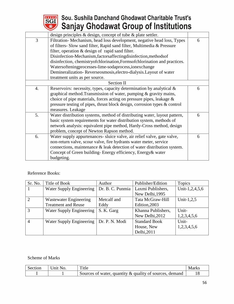
56
design principles & design, concept of tube & plate settler.
3 Filtration- Mechanism, head loss development, negative head loss, Types
of filters- Slow sand filter, Rapid sand filter, Multimedia & Pressure
filter, operation & design of rapid sand filter.
Disinfection-Mechanism,factorsaffectingdisinfection,methodsof
disinfection, chemistryofchlorination,Formsofchlorination and practices.
Watersofteningprocesses-lime-sodaprocess,ionexchange
Demineralization- Reverseosmosis,electro-dialysis.Layout of water
treatment units as per source.
6
Section II
4. Reservoirs: necessity, types, capacity determination by analytical &
graphical method.Transmission of water, pumping & gravity mains,
choice of pipe materials, forces acting on pressure pipes, leakage &
pressure testing of pipes, thrust block design, corrosion types & control
measures. Leakage
6
5. Water distribution systems, method of distributing water, layout pattern,
basic system requirements for water distribution system, methods of
network analysis: equivalent pipe method, Hardy-Cross method, design
problem, concept of Newton Rapson method.
6
6. Water supply appurtenances- sluice valve, air relief valve, gate valve,
non-return valve, scour valve, fire hydrants water meter, service
connections, maintenance & leak detection of water distribution system.
Concept of Green building- Energy efficiency, Energy& water
budgeting.
6
Reference Books:
Sr. No. Title of Book Author Publisher/Edition Topics
1 Water Supply Engineering Dr. B. C. Punmia Laxmi Publishers,
New Delhi,1995
Unit-1,2,4,5,6
2 Wastewater Engineering
Treatment and Reuse
Metcalf and
Eddy
Tata McGraw-Hill
Edition,2003
Unit-1,2,5
3 Water Supply Engineering S. K. Garg Khanna Publishers,
New Delhi,2012
Unit-
1,2,3,4,5,6
4 Water Supply Engineering Dr. P. N. Modi Standard Book
House, New
Delhi,2011
Unit-
1,2,3,4,5,6
Scheme of Marks
Section Unit No. Title Marks
I 1 Sources of water, quantity & quality of sources, demand 18
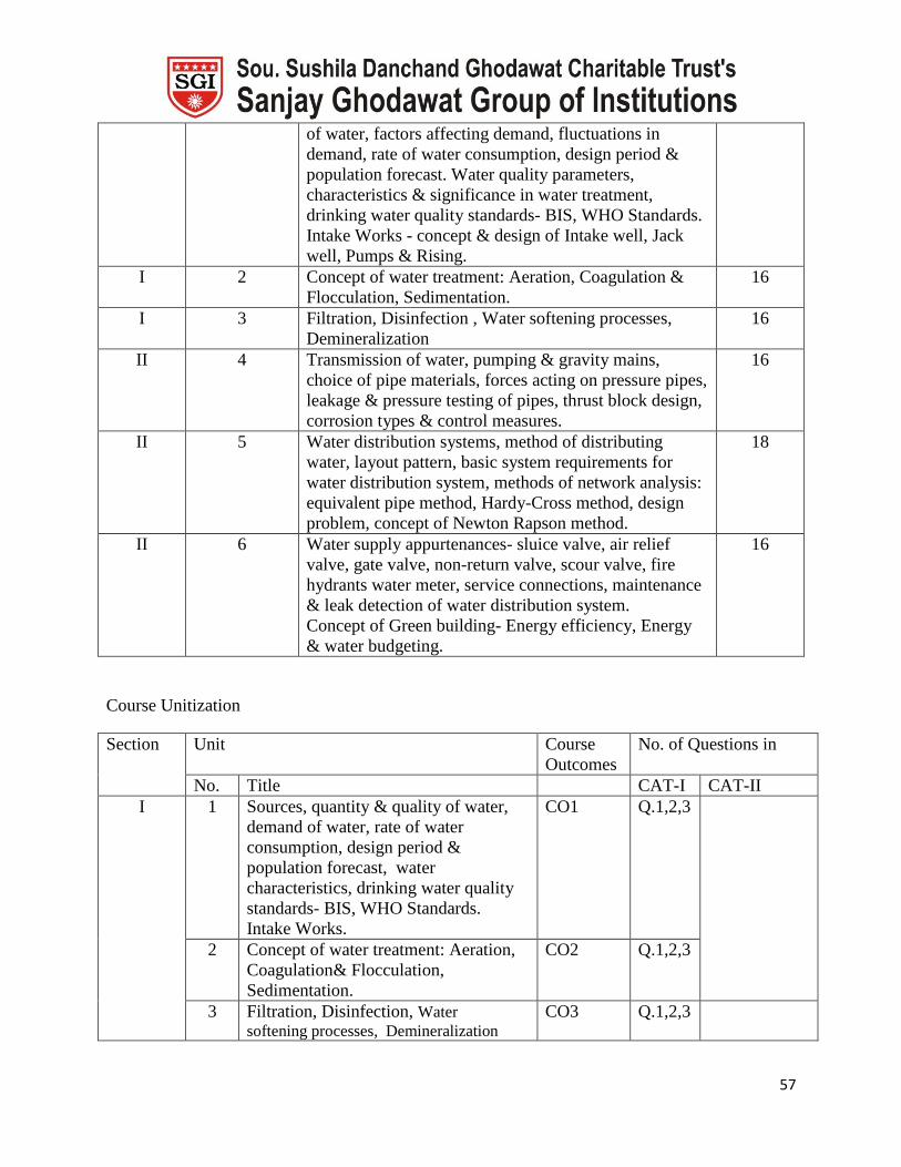
57
of water, factors affecting demand, fluctuations in
demand, rate of water consumption, design period &
population forecast. Water quality parameters,
characteristics & significance in water treatment,
drinking water quality standards- BIS, WHO Standards.
Intake Works - concept & design of Intake well, Jack
well, Pumps & Rising.
I 2 Concept of water treatment: Aeration, Coagulation &
Flocculation, Sedimentation.
16
I 3 Filtration, Disinfection , Water softening processes,
Demineralization
16
II 4 Transmission of water, pumping & gravity mains,
choice of pipe materials, forces acting on pressure pipes,
leakage & pressure testing of pipes, thrust block design,
corrosion types & control measures.
16
II 5 Water distribution systems, method of distributing
water, layout pattern, basic system requirements for
water distribution system, methods of network analysis:
equivalent pipe method, Hardy-Cross method, design
problem, concept of Newton Rapson method.
18
II 6 Water supply appurtenances- sluice valve, air relief
valve, gate valve, non-return valve, scour valve, fire
hydrants water meter, service connections, maintenance
& leak detection of water distribution system.
Concept of Green building- Energy efficiency, Energy
& water budgeting.
16
Course Unitization
Section
Unit Course
Outcomes
No. of Questions in
No. Title CAT-I CAT-II
I 1 Sources, quantity & quality of water,
demand of water, rate of water
consumption, design period &
population forecast, water
characteristics, drinking water quality
standards- BIS, WHO Standards.
Intake Works.
CO1 Q.1,2,3
2 Concept of water treatment: Aeration,
Coagulation& Flocculation,
Sedimentation.
CO2 Q.1,2,3
3 Filtration, Disinfection, Water
softening processes, Demineralization
CO3 Q.1,2,3

58
II 4 Transmission of water, pumping &
gravity mains, choice of pipe materials,
forces acting on pressure pipes, leakage
& pressure testing of pipes, thrust block
design, corrosion types & control
measures.
CO4 Q.1,2,3
5 Water distribution systems, method of
distributing water, layout pattern, basic
system requirements for water
distribution system, methods of
network analysis: equivalent pipe
method, Hardy-Cross method, design
problem, concept of Newton Rapson
method.
CO5 Q.1,2,3
6 Water supply appurtenances- sluice
valve, air relief valve, gate valve, non-
return valve, scour valve, fire hydrants
water meter, service connections,
maintenance & leak detection of water
distribution system. Concept of Green
Buildings.
CO6 Q.1,2
Unit wise Lesson Plan
Section I
Unit No 1 Unit Title Sources, quantity & quality of water,
demand of water, rate of water consumption,
design period & population forecast, water
characteristics, drinking water quality
standards- BIS, WHO Standards, Intake
Works.
Planned
Hrs.
06
Unit Outcomes
At the end of this unit the students should be able to:
UO1 To understand sources, quantity & quality of water. CO1
UO2 To understand demand of water & water budget. CO1
UO3 To understand& to make analysis of design period & population forecast of
water.
CO1
UO4 To understand characteristics and significance in water. CO1
UO5 To understand & implantation drinking water quality standards- BIS, WHO
Standards for water treatment plant unit.
CO1
UO6 To understand concept and design of Intake well, CO1
UO7 To understand concept and design of Jack well, Pumps and Rising mains CO1
Lesson schedule
Class Details to be covered

59
No.
1 Sources of water- surface & sub- surface, quantity of water- rate of water consumption
data, quality of water- all the water quality parameters-PH, TDS, Hardness and
Chlorides.
2 Demand of water- factors affecting demand- climatic, fluctuations in demand- daily,
hourly, monthly and yearly, rate of water consumption, water budget for small town
and large town.
3 Design period for water treatment unit & population forecast- arithmetic method,
geometric method, incremental increase method, graphical method.
4 water characteristics- physical, chemical and biological & significance of water for
utility purposes
5 drinking water quality standards- BIS, WHO Standards for water treatment plant unit
6 concept and design of Intake well- structure of Intake well, components of Intake well
design parameters of Intake well
7 concept and design of Intake well- structure of Jack well, Pumps and Rising mains,
components of Jack well, Pumps and Rising mains, design parameters of Jack well,
Pumps and Rising mains.
Review Questions
Q1 Explain various factors which directly affect the per capita demand of town CO1
Q2 Explain fluctuation in water demand. CO1
Q3 Explain significance in water supply system CO1
Q4 Explain types of intakes with neat sketch CO1
Section I
Unit No 2 Unit Title Concept of water treatment: Aeration,
Coagulation& Flocculation, Sedimentation,
Planned
Hrs.
06
Unit Outcomes
At the end of this unit the students should be able to:
UO1 To understand concept of aeration system and types of aerators, analyze
design of cascade aerator.
CO2
UO2 To understand concept of coagulation and flocculation- factors affecting,
destabilization of colloidal particles
CO2
UO3 To understand types of dosing of coagulants, selection of coagulants and jar
tests procedure, Also to study the concept of sedimentation and theory, types
of settling and to analyze design principles of sedimentation tank.
CO2
UO4 To understand the design of rapid mixer and flocculator. Also to study the
types of sedimentation tanks
CO2
UO5 To understand concept of tube and plate settler and to analyze design of tube
and plate settler.
CO2
Lesson schedule
Class
No.
Details to be covered
3 concept of aeration system- process, significance of aeration system, types of aerators-
gravity aerators, spray aerator, diffused aerators, design parameter of cascade aerator
4 concept of coagulation and flocculation process- type of water to used of coagulation
and flocculation process factors affecting,- temperature, size of particle, PH,

60
destabilization of colloidal particles- charges on the colloidal particles, size of particle
5 types of dosing of coagulants- alum, FeSO4, FeCl3, selection of coagulants- depend
upon of PH of the water, jar tests procedure- jar tests experiment for optimum dose,
the concept of sedimentation and theory, types of settling – discrete, flocculent,
hindered, compress, design principles of sedimentation tank- design parameter for
sedimentation tank
6 the design of rapid mixer and flocculator- design parameter of rapid mixer and
flocculator, the types of sedimentation tanks- based on shapes and structure
7 concept of tube and plate settler- process of tube and plate settler, design of tube and
plate settler- design parameter of tube and plate settler.
Review Questions
Q1 Explain theory of coagulation CO2
Q2 A water treatment plant to treat 60 mld of water. Alum dose required is 40
mg/lit. Assuming water temperature 20oC and G-t value of 4000.
Determine flocculent tank size and monthly alum requirement.
CO2
Section I
Unit No 3 Unit Title Filtration, Disinfection ,Water softening
processes, Demineralization
Planned
Hrs.
06
Unit Outcomes
At the end of this unit the students should be able to:
UO1 To understand the types of filters and study slow sand filter, rapid sand filter. CO3
UO2 To understand concept of multimedia and Pressure filter and to study the
operation and design of rapid sand filter and rate control patterns.
CO3
UO3 To understand concept of disinfection. To study mechanism of disinfection,
factors affecting disinfection,To understand methods of disinfection,
chemistry of chlorination. To study of chlorination practices, points of
chlorination, application of chlorine
CO3
UO4 To understand apply water softening processes in water treatment unit. CO3
UO5 To understand apply various demineralization process in the water
treatment unit
CO3
UO6 To understandsequencing of treatment for various qualities of surface &
ground water
CO3
Lesson schedule
Class
No.
Details to be covered
1 The types of filters - slow sand filter, rapid sand filter, working process and design
parameter slow sand filter, rapid sand filter.
2 concept of multimedia and Pressure filter- process of multimedia and Pressure filter,
the operation and design of rapid sand filter, rate control patterns- flow rate, concept
of disinfection- process and mechanism of disinfection, U.V, chlorination, factors
affecting disinfection- dose, temperature
3 methods of disinfection- pre chlorination, post chlorination, de chlorination chemistry
of chlorination- reaction in chlorination, practices and points of chlorination- break
point chlorination, application of chlorine- significance of chlorination
4 Water softening processes -lime-soda process, ion exchange methods and working

61
process
5 various demineralization process -- Reverse osmosis, ion exchange, electro dialysis
methods and working process
6 sequencing of treatment for various qualities of surface & ground water- sequencing
of treatment layout
Review Questions
Q1 Explain the difference between rapid sand & slow sand filter CO3
Q2 Explain the mechanism of disinfection CO3
Q3 What is the need of water softening CO3
Q4 Explain Electrolysis process of demineralization. CO3
Section II
Unit No 4 Unit Title Transmission of water, pumping and gravity
mains, choice of pipe materials, forces acting
on pressure pipes, leakage and pressure
testing of pipes, thrust block design,
corrosion types and control measures.
Planned
Hrs.
06
Unit Outcomes
At the end of this unit the students should be able to:
UO1 To understand transmission of water, pumping and gravity in pipeline and
also to study selection and choice of pipe materials.
CO4
UO2 To understand various forces acting on pressure pipes CO4
UO3 To understand leakage and pressure testing of pipes and to solve the
problem on thrust block design
CO4
UO4 To understand various corrosion types and control measures. CO4
Lesson schedule
Class
No.
Details to be covered
1 transmission of water- methods, pumping and gravity in pipeline, selection and choice
of pipe materials- G.I,PVC, asbestos, cement, HDPE, LDPE, types of pipe, types of
conduit, types of pipe joints
2 various forces acting on pressure pipes- internal forces, external forces, bend forces
3 leakage and pressure testing of pipes – various methods, the problem on thrust block
design in pipeline
4 various corrosion types - various methods, control measures- anticorrosive chemicals
use
Review Questions
Q1 What are the various methods of network analysis for water distribution
system?
CO4
Q2 Explain with neat sketch the pressure testing of newly laid main. CO4
Q3 Explain with diagram laying out process of water supply mains. CO4
Section II
Unit No 5 Unit Title Water distribution systems, method of
distributing water, layout pattern, basic
system requirements for water distribution
system, methods of network analysis:
Planned
Hrs.
06

62
equivalent pipe method, Hardy-Cross
method, design problem, concept of Newton
Rapson method.
Unit Outcomes
At the end of this unit the students should be able to:
UO1 To understand concept and method of water distribution systems. CO5
UO2 To understand various layout pattern of water distribution systems. CO5
UO3 To understand basic system requirements for water distribution system CO5
UO4 To understand methods and solve design problem on network analysis in
equivalent pipe method.
CO5
UO5 To understand equation and solve design problem on network analysis in
Hardy-Cross method design problem
CO5
UO6 To understand concept of Newton Rapson method on network analysis in
pipeline method.
CO5
Lesson schedule
Class
No.
Details to be covered
1 concept and method of water distribution systems- gravity, pumping and combined
methods
2 various layout pattern of water distribution systems- dead-end, grid-iron, circular and
radical system
3 basic system requirements for water distribution system
4 methods and solve design problem on network analysis in equivalent pipe method
5 equation and solve design problem on network analysis in Hardy-Cross method design
problem
6 concept of Newton Rapson method on network analysis in pipeline method
Review Questions
Q1 Write a short note on force acting on pipe CO6
Q2 Write a short note on Gravity mains CO6
Q3 Write a short note on Thrust Block CO6
Section II
Unit No 6 Unit Title Water supply appurtenances- sluice valve,
air relief valve, gate valve, non-return valve,
scour valve, fire hydrants water meter,
service connections, maintenance & leak
detection of water distribution system.
Concept of Green building- Energy
efficiency, Energy& water budgeting
Planned
Hrs.
06
Unit Outcomes
At the end of this unit the students should be able to:
UO1 To understand water supply appurtenances- sluice valve and air relief valve. CO6
UO2 To understand non-return valve and scour valve, CO6
UO3 To understand fire hydrants water meter, service connections, maintenance CO6
UO4 To understand leak detection of water distribution system CO6
UO5 To understand the concept and case study of green building. CO6
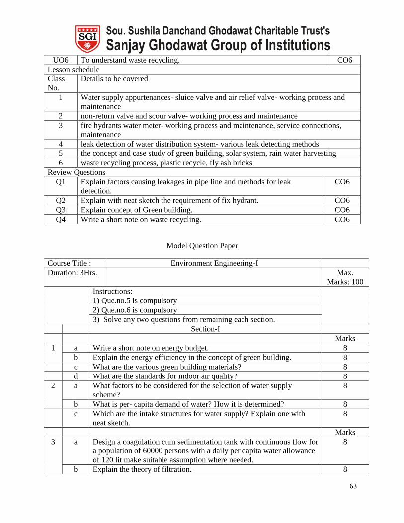
63
UO6 To understand waste recycling. CO6
Lesson schedule
Class
No.
Details to be covered
1 Water supply appurtenances- sluice valve and air relief valve- working process and
maintenance
2 non-return valve and scour valve- working process and maintenance
3 fire hydrants water meter- working process and maintenance, service connections,
maintenance
4 leak detection of water distribution system- various leak detecting methods
5 the concept and case study of green building, solar system, rain water harvesting
6 waste recycling process, plastic recycle, fly ash bricks
Review Questions
Q1 Explain factors causing leakages in pipe line and methods for leak
detection.
CO6
Q2 Explain with neat sketch the requirement of fix hydrant. CO6
Q3 Explain concept of Green building. CO6
Q4 Write a short note on waste recycling. CO6
Model Question Paper
Course Title : Environment Engineering-I
Duration: 3Hrs. Max.
Marks: 100
Instructions:
1) Que.no.5 is compulsory
2) Que.no.6 is compulsory
3) Solve any two questions from remaining each section.
Section-I
Marks
1 a Write a short note on energy budget. 8
b Explain the energy efficiency in the concept of green building. 8
c What are the various green building materials? 8
d What are the standards for indoor air quality? 8
2 a What factors to be considered for the selection of water supply
scheme?
8
b What is per- capita demand of water? How it is determined? 8
c Which are the intake structures for water supply? Explain one with
neat sketch.
8
Marks
3 a Design a coagulation cum sedimentation tank with continuous flow for
a population of 60000 persons with a daily per capita water allowance
of 120 lit make suitable assumption where needed.
8
b Explain the theory of filtration. 8

64
4 a Write short note on water softening. Explain lime-soda process for
softening.
8
b Write short note on following:
i)Ion-exchange
ii) Electro-dialysis
8
Marks
5
a
Write short note on any three:
Population forecast
6
b Backwash filter 6
c Sludge removal in sedimentation. 6
d Waste recycling. 6
Section-II Marks
6 a Discuss Hardy-Cross method of network analysis. 6
b Explain the basis and process of choice of pipe material for a certain
project.
c Explain importance and working of fire hydrant with sketch.
7 a Explain details about using cement concrete pipes in water supply
with advantage and disadvantage.
8
b Explain necessity, working and importance of thrust block. 8
8 a State and explain with diagram the different layout patterns adopted
for distribution of water supply in pipe network.
8
b Find equivalent length of 30cm diameter pipe for network mentioned
in table below, using Darcy’s formula.
Pipe Length Diameter
AB 300 400
BC 400 300
CD 500 200
DE 600 300
8
9 a Explain following water appurtenances with diagram.
i) Scour Valve
ii) Air Relief Valve
8
b Explain the determination of capacity of a reservoir with reference to
hydrograph method.
8
Lab Plan
Assignment Title List of experiments CO1,2,3
Batch I 1. pH
2. Acidity
3. Alkalinity
4. Chlorides content
5. Hardness – Total, temporary and permanent
6. Turbidity
7. Residual Chlorine

65
8. Dissolved Oxygen
Batch II 1. pH
2. Acidity
3. Alkalinity
4. Chlorides content
5. Hardness – Total, temporary and permanent
6. Turbidity
7. Residual Chlorine
8. Dissolved Oxygen
Batch III 1. pH
2. Acidity
3. Alkalinity
4. Chlorides content
5. Hardness – Total, temporary and permanent
6. Turbidity
7. Residual Chlorine
8. Dissolved Oxygen
Batch IV 1. pH
2. Acidity
3. Alkalinity
4. Chlorides content
5. Hardness – Total, temporary and permanent
6. Turbidity
7. Residual Chlorine
8. Dissolved Oxygen
Assignment No. 1
Assignment Title CO1,2,3,4
Batch I Visit report on a water treatment plant
Batch II Visit report on a water treatment plant
Batch III Visit report on a water treatment plant
Batch IV Visit report on a water treatment plant
Assignment No. 2
Assignment Title CO1,2,3
Batch I Design/Analysisproblemsonwatertreatmentunits
Batch II Design/Analysisproblemsonwatertreatmentunits
Batch III Design/Analysisproblemsonwatertreatmentunits
Batch IV Design/Analysisproblemsonwatertreatmentunits

66
Assignment No. 3
Assignment Title CO4,5
Batch I Analysis of distributionsystem using software
Batch II Analysis of distributionsystem using software
Batch III Analysis of distributionsystem using software
Batch IV Analysis of distributionsystem using software
List of additional assignments /experiments
Assignment No. 1
Assignment Title List of experiments CO1,2,3
Batch I Conductivity, Optimum dose of alum by jar test
Batch II Conductivity, Optimum dose of alum by jar test
Batch III Conductivity, Optimum dose of alum by jar test
Batch IV Conductivity, Optimum dose of alum by jar test
Assignment No. 1
Assignment Title Green campus CO6
Batch I To study in developed green campus and using renewable energy sources
in Sanjay Ghodawat institute, Atigre (Kolhapur)
Batch II To study in developed green campus and using renewable energy sources
in Sanjay Ghodawat institute, Atigre (Kolhapur)
Batch III To study in developed green campus and using renewable energy sources
in Sanjay Ghodawat institute, Atigre (Kolhapur)
Batch IV To study in developed green campus and using renewable energy sources
in Sanjay Ghodawat institute, Atigre (Kolhapur)
Course Plan
Course Building Planning and Design Course Code
Examination
Scheme Theory Term Work OE Total
Max. Marks -- 50 25 75
Contact
Hours/ week 2 4 -- 6
Prepared by Mrs. V.P. Patil Date 15/6/2015
Prerequisites This course requires the student to know about the basic planning and design
of public building , dimension and space requirement and norms for public
building etc.

67
Course Outcomes
At the end of the course the students should be able to:
CO1 explain space design for passage between walls, service access, stair, ramps,
and elevators
CO2 draw public building using principal of planning and prepare plan for
corporation submission as per building byelaws and regulation required for
construction in corporation area
CO3 explain building drawing at various stages like first floor, second floor, terrace
plan and demonstrate about plumbing system, air conditioning system,
electrification system, ventilation
CO4 explain and draw perspective drawings, parallel perspective and angular
perspective, introduction to the nature of architecture and interior designing
Mapping of COs with POs
POs
COs a b c d e f g h i j k l
CO1 √ √ √ √ √ √ √ √
CO2 √ √ √ √ √
CO3 √ √ √ √ √ √ √ √
CO4 √ √ √ √ √
Course Contents
Unit No. Title No. of
Hours
1. Dimensions & space requirement in relation to body measurements,
space design for passage between walls, service access, stair, ramps,
elevators
01
2. Planning and Design, site selection, site layout for various types of
building such as:
a)Educational buildings- Younger age range, middle age range, older
age range, School for mentally retarded
b)Building for health- Sanitorium, Hospitals
c)Assembly buildings- Recreational Halls, Community halls, Cinema
theatres, Gymnasiums, Restaurant, Temples, Dance halls, Clubs.
d)Business and Mercantile buildings- Shops, Banks, Markets and
Departmental stores
e)Industrial buildings- Factories, Warehouse
f) Office and other buildings- Post offices, Administrative buildings
etc.
16
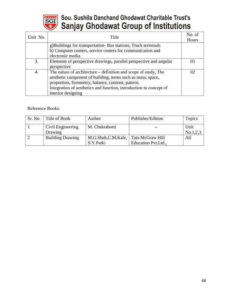
68
Unit No. Title No. of
Hours
g)Buildings for transportation- Bus stations, Truck terminals
h) Computer centers, service centers for communication and
electronic media.
3. Elements of perspective drawings, parallel perspective and angular
perspective
05
4. The nature of architecture – definition and scope of study, The
aesthetic component of building, terms such as mass, space,
proportion, Symmetry, balance, contrast, pattern.
Integration of aesthetics and function, introduction to concept of
interior designing
02
Reference Books:
Sr. No. Title of Book Author Publisher/Edition Topics
1 Civil Engineering
Drawing
M. Chakraborti -- Unit
No.1,2,3
2 Building Drawing M.G.Shah,C.M.Kale,
S.Y.Patki
Tata McGraw Hill
Education Pvt.Ltd.,
All