sheet metal working processes - gantep.edu.trbozdana/me333_7.pdf · cutting of sheet metal is...
TRANSCRIPT
ME 333 – Manufacturing Processes II
Dr. A. Tolga Bozdanawww.gantep.edu.tr/~bozdana
Mechanical EngineeringUniversity of Gaziantep
Chapter 7
Sheet Metal Working Processes
11
Introduction
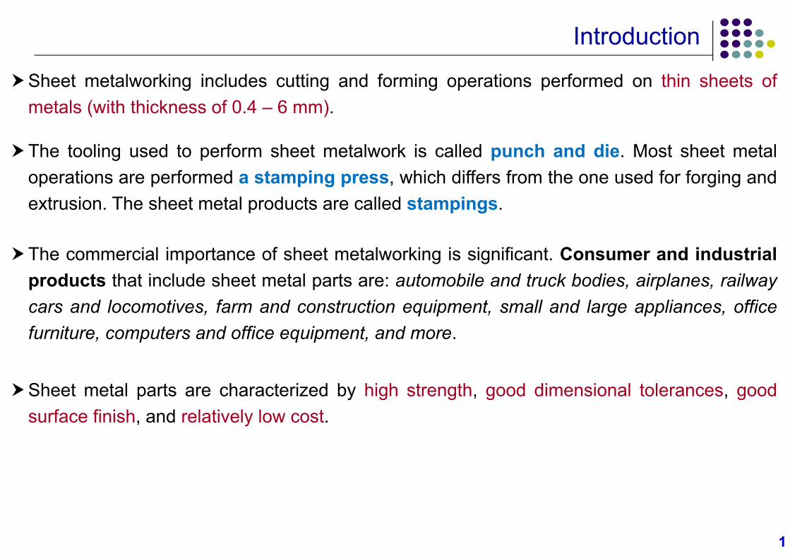
Sheet metalworking includes cutting and forming operations performed on thin sheets ofmetals (with thickness of 0.4 – 6 mm).
The tooling used to perform sheet metalwork is called punch and die. Most sheet metaloperations are performed a stamping press, which differs from the one used for forging andextrusion. The sheet metal products are called stampings.
The commercial importance of sheet metalworking is significant. Consumer and industrialproducts that include sheet metal parts are: automobile and truck bodies, airplanes, railwaycars and locomotives, farm and construction equipment, small and large appliances, officefurniture, computers and office equipment, and more.
Sheet metal parts are characterized by high strength, good dimensional tolerances, goodsurface finish, and relatively low cost.
22
Sheet Metalworking Processes
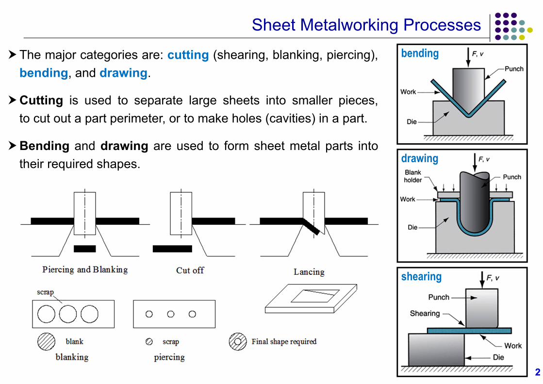
The major categories are: cutting (shearing, blanking, piercing),bending, and drawing.
Cutting is used to separate large sheets into smaller pieces,to cut out a part perimeter, or to make holes (cavities) in a part.
Bending and drawing are used to form sheet metal parts intotheir required shapes.
bending
drawing
shearing
33
Sheet Metalworking Processes
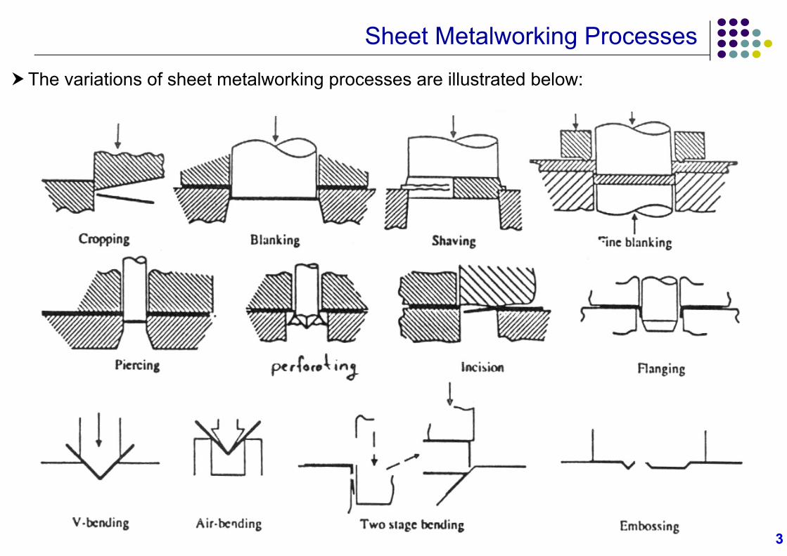
The variations of sheet metalworking processes are illustrated below:
44
Sheet Metal Cutting
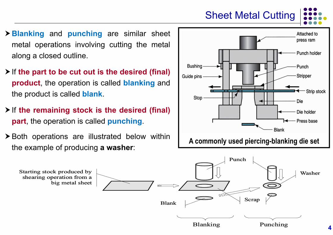
Blanking and punching are similar sheetmetal operations involving cutting the metalalong a closed outline.
If the part to be cut out is the desired (final)product, the operation is called blanking andthe product is called blank.
If the remaining stock is the desired (final)part, the operation is called punching.
Both operations are illustrated below withinthe example of producing a washer:
A commonly used piercing-blanking die set
55
Sheet Metal Cutting
Engineering Analysis
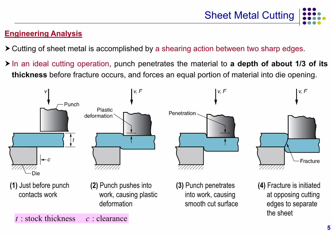
Cutting of sheet metal is accomplished by a shearing action between two sharp edges.
In an ideal cutting operation, punch penetrates the material to a depth of about 1/3 of itsthickness before fracture occurs, and forces an equal portion of material into die opening.
(1) Just before punch contacts work
(2) Punch pushes into work, causing plastic deformation
(3) Punch penetrates into work, causingsmooth cut surface
(4) Fracture is initiated at opposing cutting edges to separate the sheet
: stock thickness : clearancet c
66
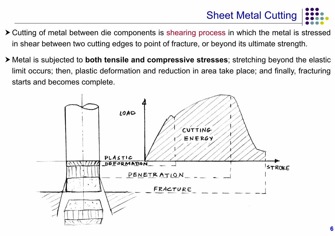
Sheet Metal CuttingCutting of metal between die components is shearing process in which the metal is stressed
in shear between two cutting edges to point of fracture, or beyond its ultimate strength.
Metal is subjected to both tensile and compressive stresses; stretching beyond the elasticlimit occurs; then, plastic deformation and reduction in area take place; and finally, fracturingstarts and becomes complete.
77
Sheet Metal CuttingClearances
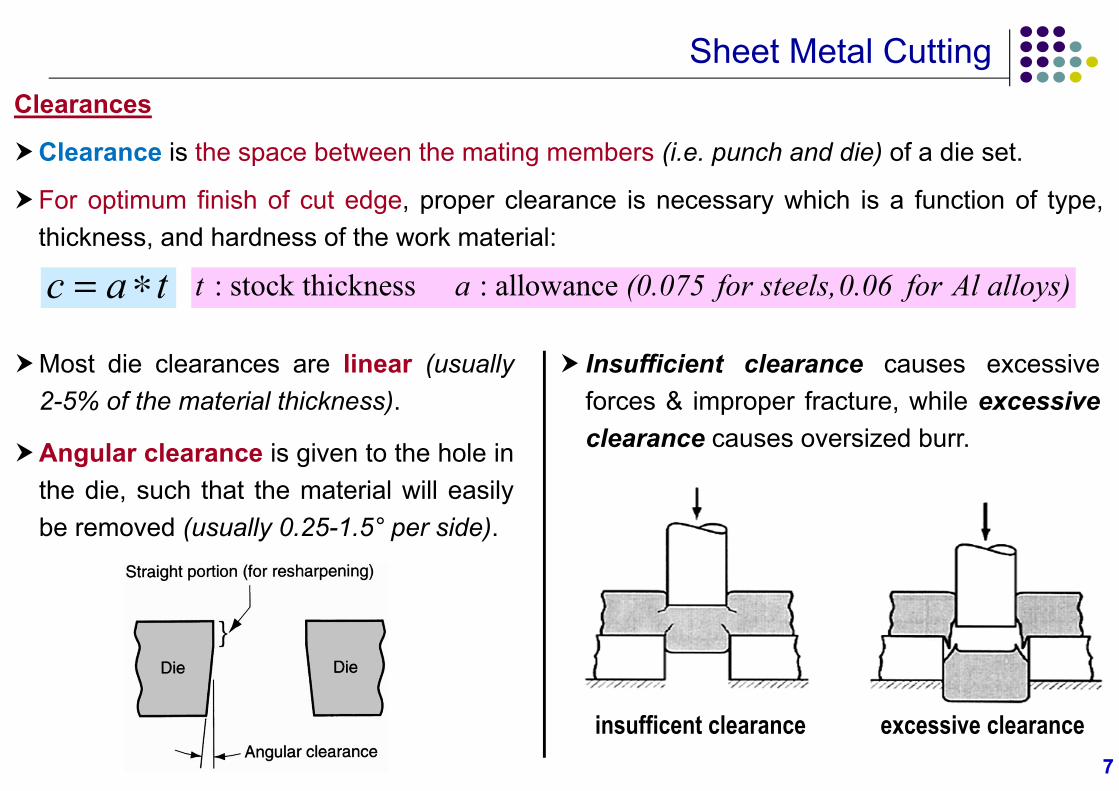
Clearance is the space between the mating members (i.e. punch and die) of a die set.
For optimum finish of cut edge, proper clearance is necessary which is a function of type,thickness, and hardness of the work material:
c a t
Most die clearances are linear (usually2-5% of the material thickness).
Angular clearance is given to the hole inthe die, such that the material will easilybe removed (usually 0.25-1.5° per side).
Insufficient clearance causes excessiveforces & improper fracture, while excessiveclearance causes oversized burr.
: stock thickness : allowance t a (0.075 for steels, 0.06 for Al alloys)
insufficent clearance excessive clearance
88
Sheet Metal Cutting
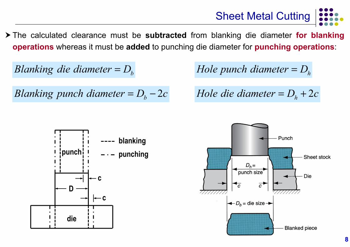
The calculated clearance must be subtracted from blanking die diameter for blankingoperations whereas it must be added to punching die diameter for punching operations:
2bBlanking punch diameter D c
bBlanking die diameter D hHole punch diameter D
2hHole die diameter D c
punch
die
c
cD
blankingpunching
99
Sheet Metal Cutting
Cutting Force
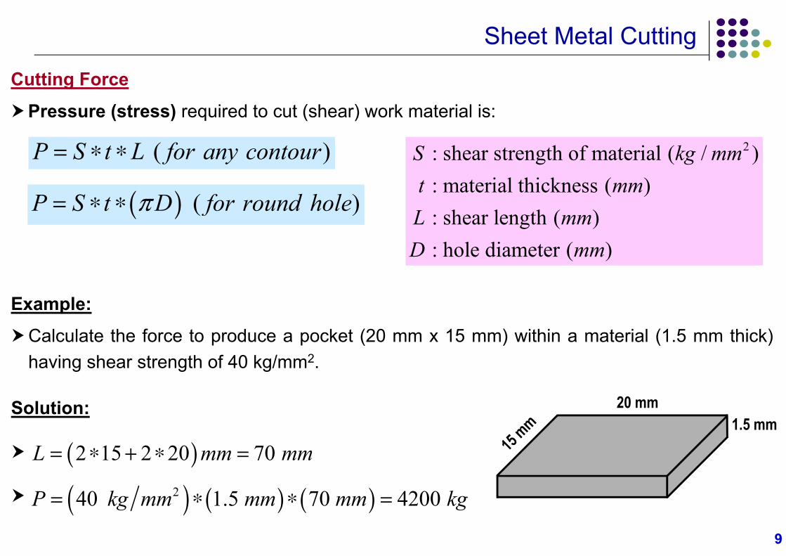
Pressure (stress) required to cut (shear) work material is:
( )P S t L for any contour
( )P S t D for round hole
Example:
Calculate the force to produce a pocket (20 mm x 15 mm) within a material (1.5 mm thick)having shear strength of 40 kg/mm2.
Solution:
20 mm1.5 mm
240 1.5 70 4200 P kg mm mm mm kg
2 15 2 20 70 L mm mm
2: shear strength of material ( / ) : material thickness ( ) : shear length ( ) : hole diameter ( )
S kg mmt mmL mmD mm
1010
Sheet Metal CuttingTools and Dies
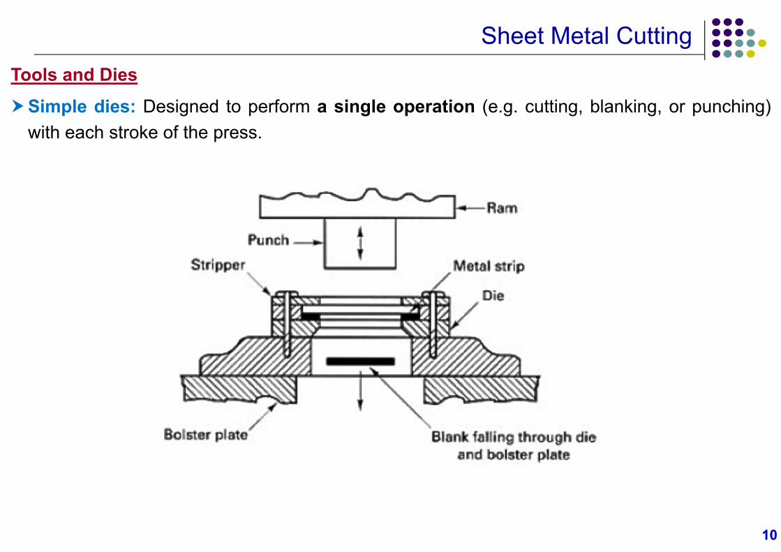
Simple dies: Designed to perform a single operation (e.g. cutting, blanking, or punching)with each stroke of the press.
1111
Sheet Metal CuttingTools and Dies
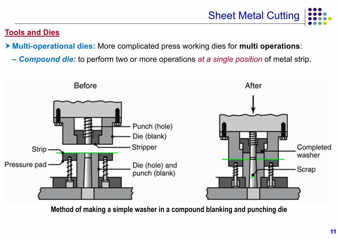
Multi-operational dies: More complicated press working dies for multi operations:
– Compound die: to perform two or more operations at a single position of metal strip.
Method of making a simple washer in a compound blanking and punching die
1212
Sheet Metal Cutting
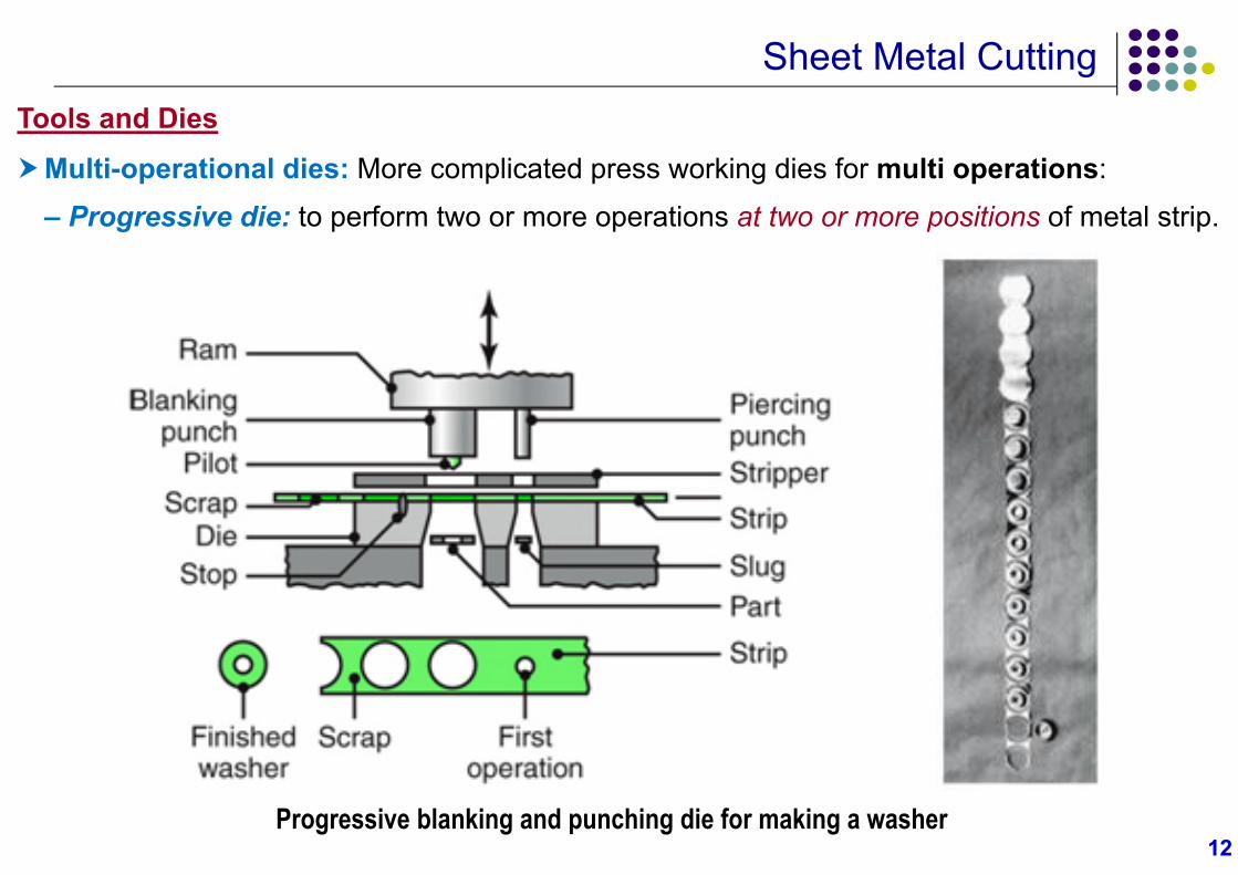
Progressive blanking and punching die for making a washer
Tools and Dies
Multi-operational dies: More complicated press working dies for multi operations:
– Progressive die: to perform two or more operations at two or more positions of metal strip.
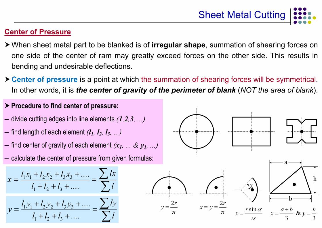
Sheet Metal CuttingCenter of Pressure
When sheet metal part to be blanked is of irregular shape, summation of shearing forces onone side of the center of ram may greatly exceed forces on the other side. This results inbending and undesirable deflections.
Center of pressure is a point at which the summation of shearing forces will be symmetrical.In other words, it is the center of gravity of the perimeter of blank (NOT the area of blank).
α
a
b
h
sinrx
2ry
2rx y
&
3 3a b hx y
Procedure to find center of pressure:– divide cutting edges into line elements (1,2,3, ...)
– find length of each element (l1, l2, l3, ...)
– find center of gravity of each element (x1, ... & y1, ...)
– calculate the center of pressure from given formulas:
1 1 2 2 3 3
1 2 3
........
lxl x l x l xxl l l l
1 1 2 2 3 3
1 2 3
........
lyl y l y l yyl l l l
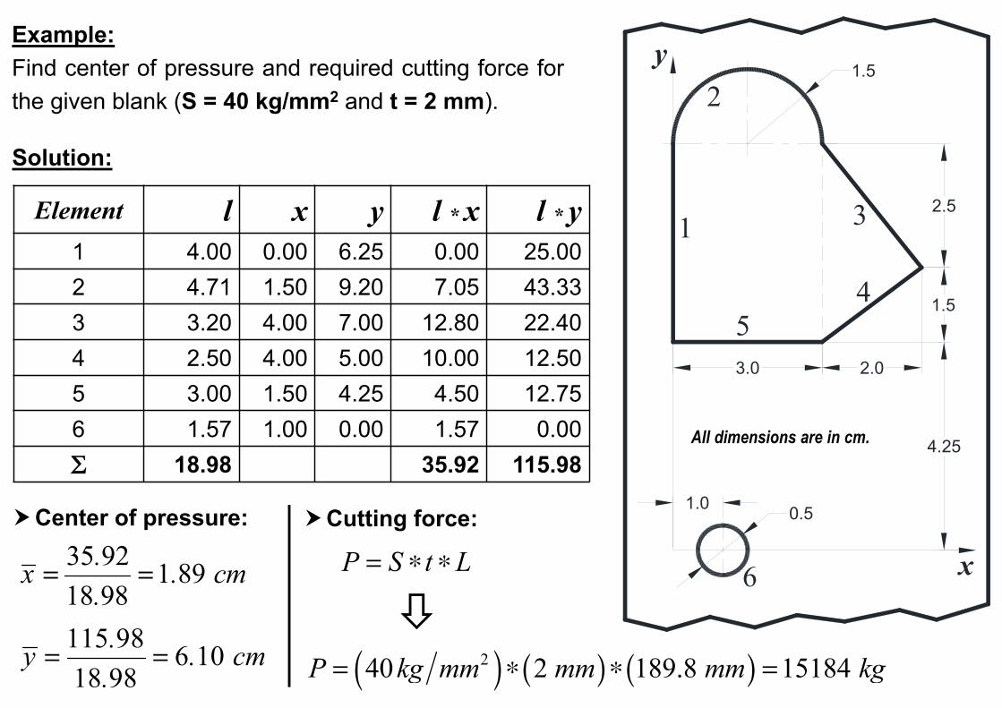
Example:Find center of pressure and required cutting force forthe given blank (S = 40 kg/mm2 and t = 2 mm).
Solution:
Center of pressure:
Element l x y l * x l * y1 4.00 0.00 6.25 0.00 25.002 4.71 1.50 9.20 7.05 43.333 3.20 4.00 7.00 12.80 22.404 2.50 4.00 5.00 10.00 12.505 3.00 1.50 4.25 4.50 12.756 1.57 1.00 0.00 1.57 0.00 18.98 35.92 115.98
35 92 1 89 18 98
.x . cm
.
115 98 6 10 18 98
.y . cm.
P S t L Cutting force:
240 2 189.8 15184 P kg mm mm mm kg
1.5
1.0 0.5
4.25
6
3.0
1
51.5
2.0
2.5
4
3
2
x
y
All dimensions are in cm.
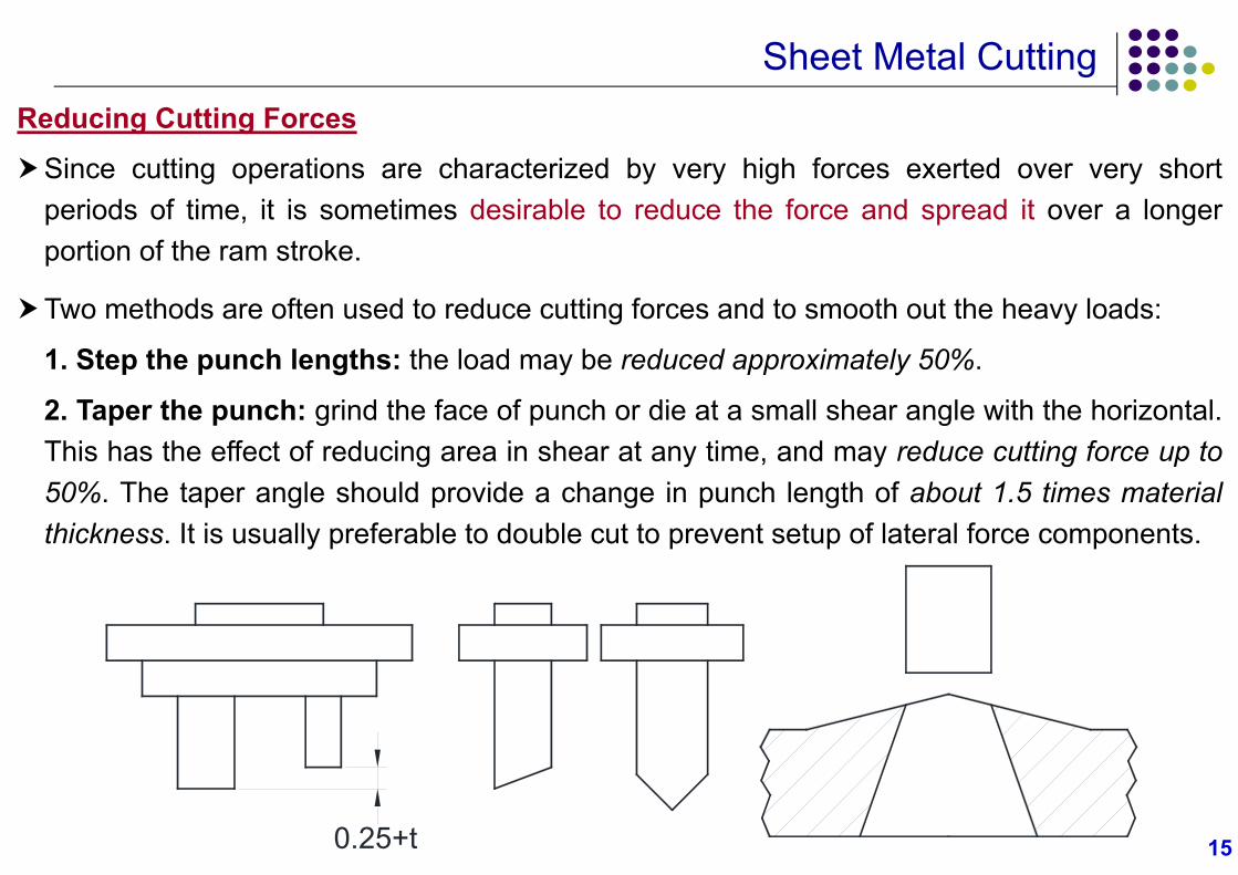
Sheet Metal CuttingReducing Cutting Forces
Since cutting operations are characterized by very high forces exerted over very shortperiods of time, it is sometimes desirable to reduce the force and spread it over a longerportion of the ram stroke.
Two methods are often used to reduce cutting forces and to smooth out the heavy loads:
1. Step the punch lengths: the load may be reduced approximately 50%.
2. Taper the punch: grind the face of punch or die at a small shear angle with the horizontal.This has the effect of reducing area in shear at any time, and may reduce cutting force up to50%. The taper angle should provide a change in punch length of about 1.5 times materialthickness. It is usually preferable to double cut to prevent setup of lateral force components.
0.25+t 15
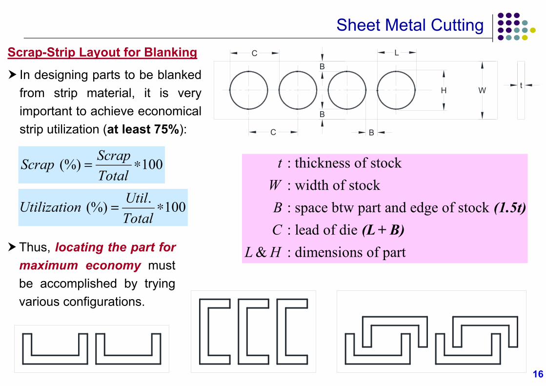
Sheet Metal CuttingScrap-Strip Layout for Blanking
In designing parts to be blankedfrom strip material, it is veryimportant to achieve economicalstrip utilization (at least 75%):
(%) 100ScrapScrapTotal
.(%) 100UtilUtilizationTotal
Thus, locating the part formaximum economy mustbe accomplished by tryingvarious configurations.
16
C
L
B
B
B
H tW
C
: thickness of stock : width of stock : space btw part and edge of stock : lead of die
& : dimensions of part
tWBC
L H
(1.5t)(L + B)
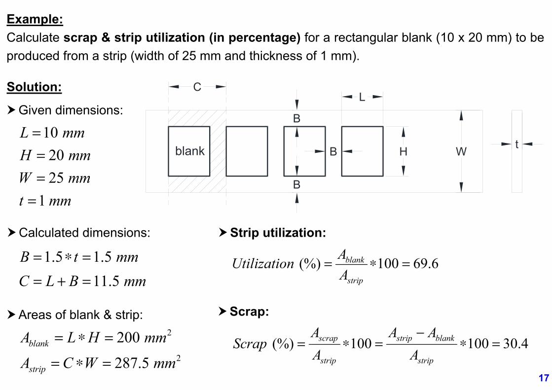
Example:Calculate scrap & strip utilization (in percentage) for a rectangular blank (10 x 20 mm) to beproduced from a strip (width of 25 mm and thickness of 1 mm).
Solution:L
B
B
B
H tW
C
blank
Given dimensions:
10 L mm20 H mm25 W mm
1 t mm
Calculated dimensions:
1.5 1.5 B t mm 11.5 C L B mm
Areas of blank & strip:2200 blankA L H mm
2287.5 stripA C W mm
Strip utilization:
(%) 100 69.6blank
strip
AUtilizationA
Scrap:
(%) 100 100 30.4scrap strip blank
strip strip
A A AScrap
A A
17
1818
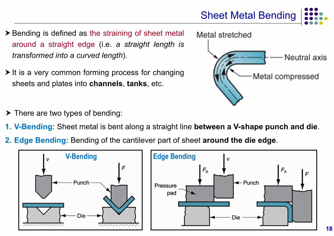
Sheet Metal BendingBending is defined as the straining of sheet metal
around a straight edge (i.e. a straight length istransformed into a curved length).
It is a very common forming process for changingsheets and plates into channels, tanks, etc.
There are two types of bending:
1. V-Bending: Sheet metal is bent along a straight line between a V-shape punch and die.
2. Edge Bending: Bending of the cantilever part of sheet around the die edge.
V-Bending Edge Bending
1919
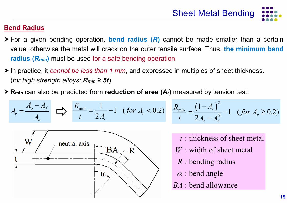
Sheet Metal BendingBend Radius
For a given bending operation, bend radius (R) cannot be made smaller than a certainvalue; otherwise the metal will crack on the outer tensile surface. Thus, the minimum bendradius (Rmin) must be used for a safe bending operation.
In practice, it cannot be less than 1 mm, and expressed in multiples of sheet thickness.(for high strength alloys: Rmin ≥ 5t)
Rmin can also be predicted from reduction of area (Ar) measured by tension test:
min 1 1 ( 0.2)2 r
r
R for At A
2
min2
11 ( 0.2)
2r
rr r
AR for At A A
o f
ro
A AA
A
: thickness of sheet metal: width of sheet metal
: bending radius : bend angle : bend allowance
tWR
BA
2020
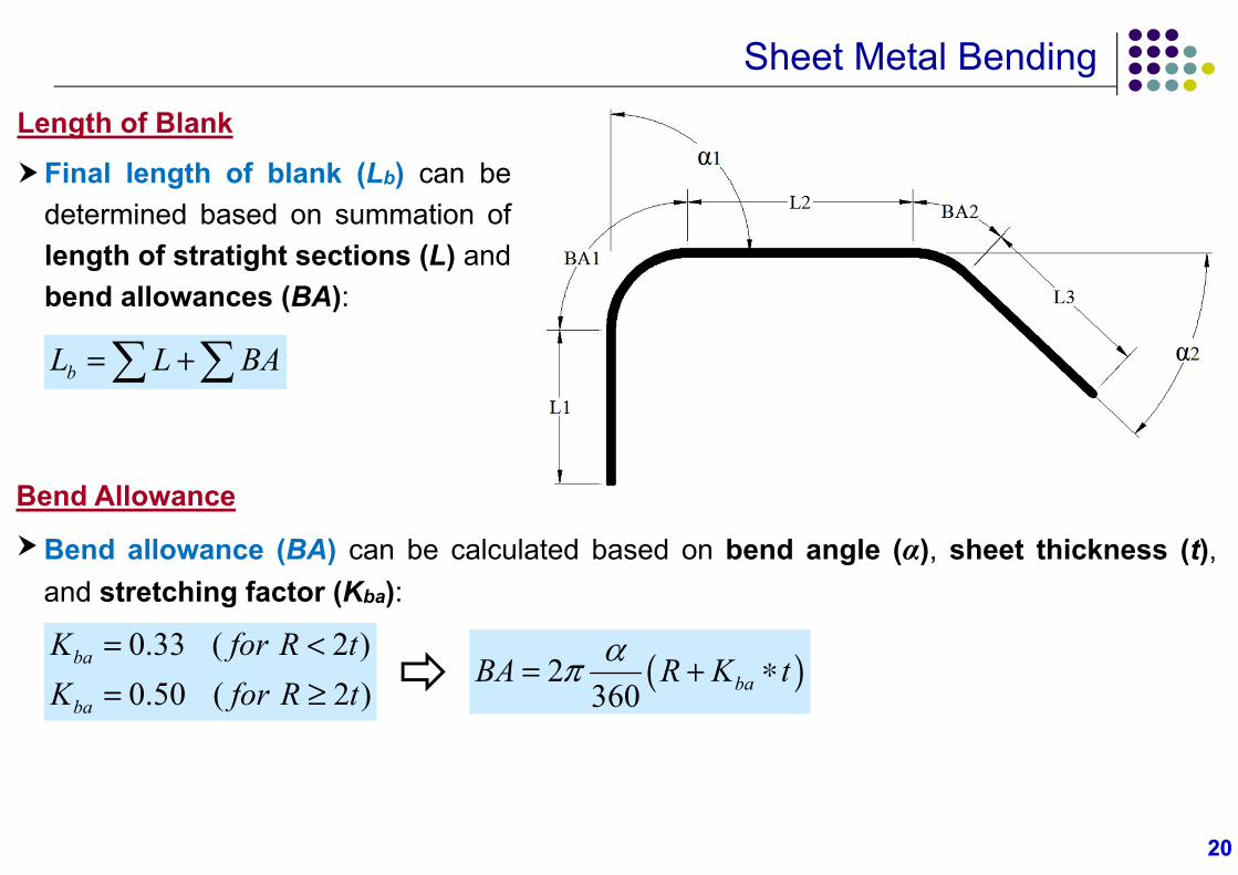
Sheet Metal BendingLength of Blank
Final length of blank (Lb) can bedetermined based on summation oflength of stratight sections (L) andbend allowances (BA):
bL L BA
2360 baBA R K t
Bend Allowance
Bend allowance (BA) can be calculated based on bend angle (α), sheet thickness (t),and stretching factor (Kba):
0.33 ( 2 )0.50 ( 2 )
ba
ba
K for R tK for R t
2121
Sheet Metal Bending
22
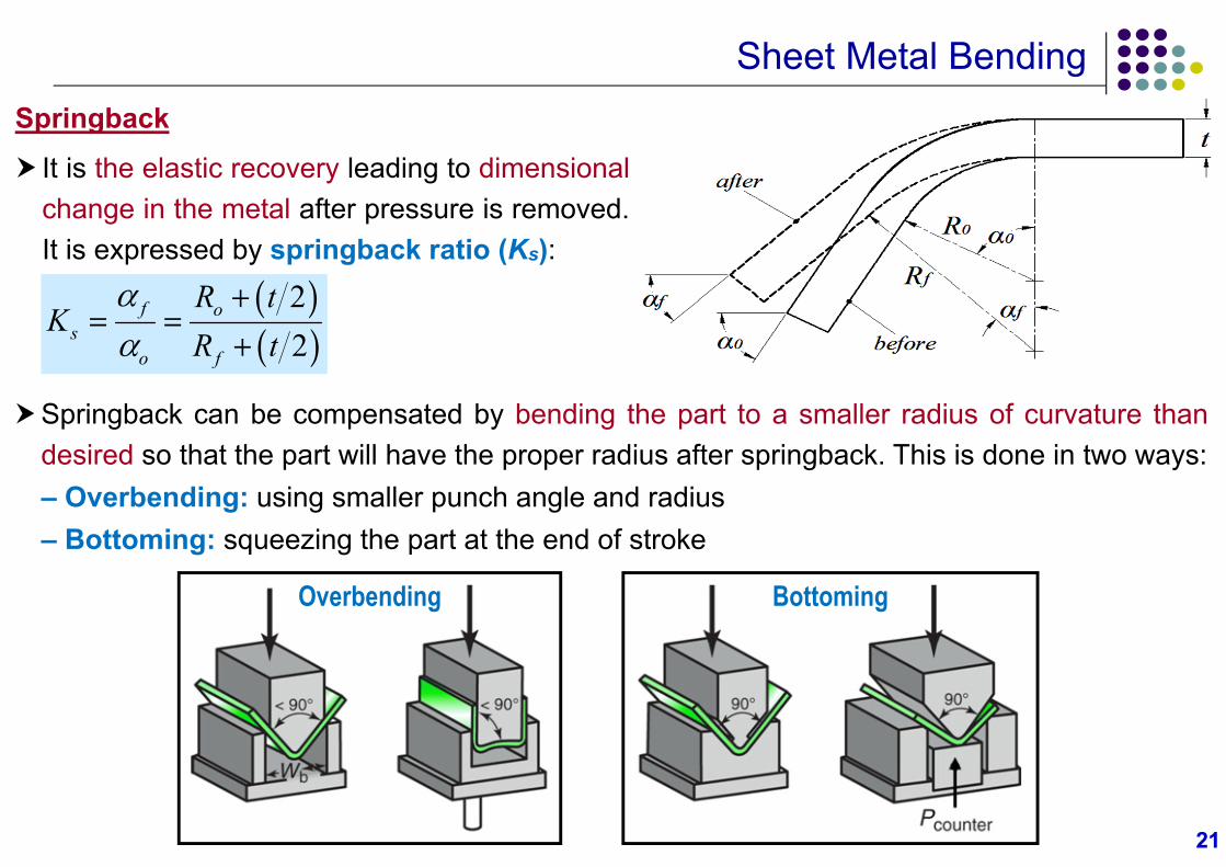
f os
o f
R tK
R t
Springback can be compensated by bending the part to a smaller radius of curvature thandesired so that the part will have the proper radius after springback. This is done in two ways:– Overbending: using smaller punch angle and radius– Bottoming: squeezing the part at the end of stroke
Springback
It is the elastic recovery leading to dimensionalchange in the metal after pressure is removed.It is expressed by springback ratio (Ks):
Overbending Bottoming
2222
Sheet Metal Bending
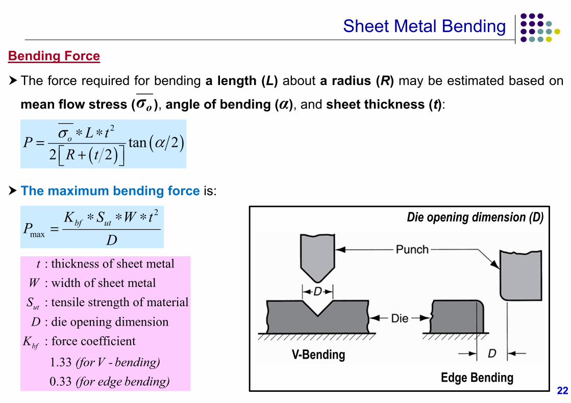
2
tan 22 2
o L tPR t
The maximum bending force is:2
maxbf utK S W t
PD
Die opening dimension (D)
V-BendingEdge Bending
: thickness of sheet metal : width of sheet metal : tensile strength of material : die opening dimension : force coefficient
1.33 0.33
ut
bf
tWSD
K
(for V - bending)(for edge bending)
Bending Force
The force required for bending a length (L) about a radius (R) may be estimated based on
mean flow stress ( ), angle of bending (α), and sheet thickness (t):oσ
2323
Sheet Metal Bending
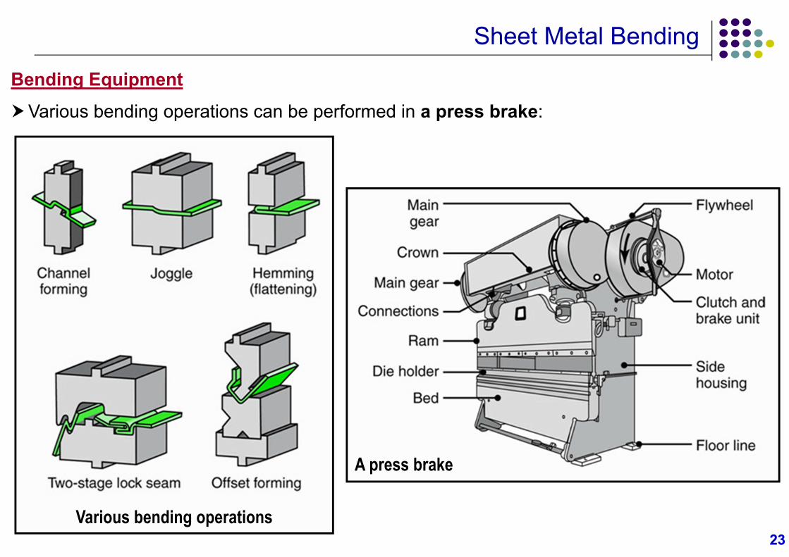
Bending Equipment
Various bending operations can be performed in a press brake:
Various bending operations
A press brake
2424
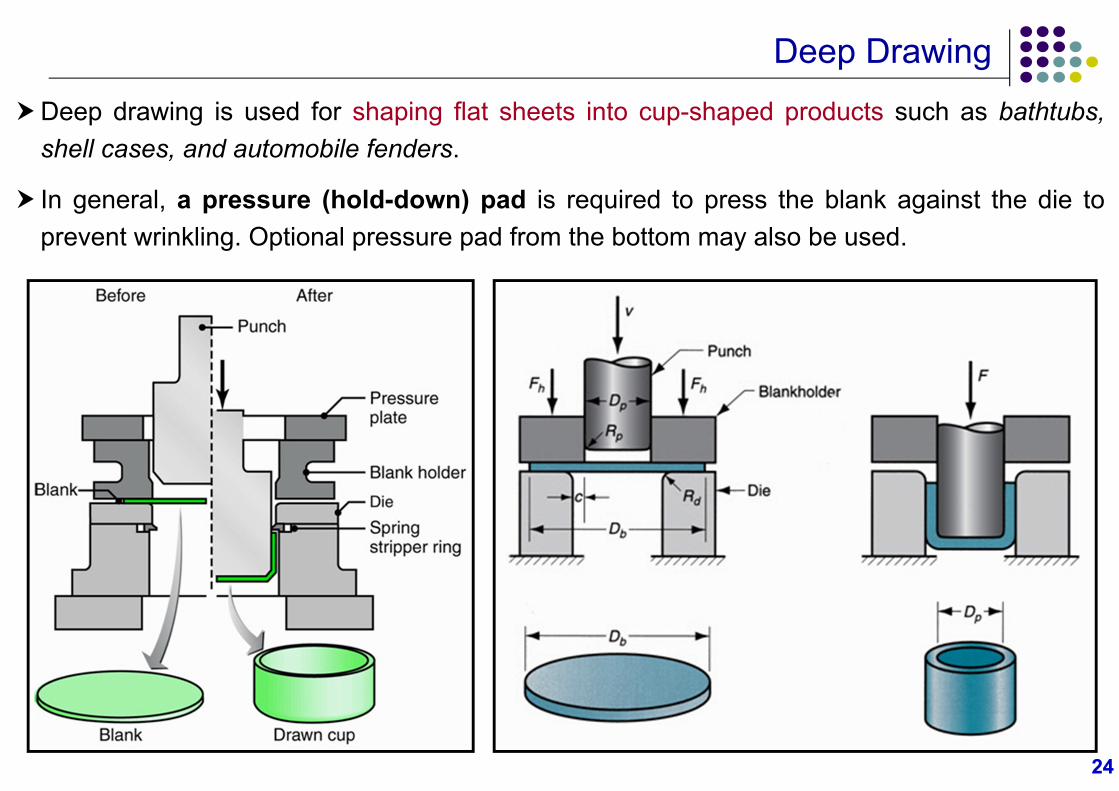
Deep DrawingDeep drawing is used for shaping flat sheets into cup-shaped products such as bathtubs,
shell cases, and automobile fenders.
In general, a pressure (hold-down) pad is required to press the blank against the die toprevent wrinkling. Optional pressure pad from the bottom may also be used.
Deep DrawingEngineering Analysis
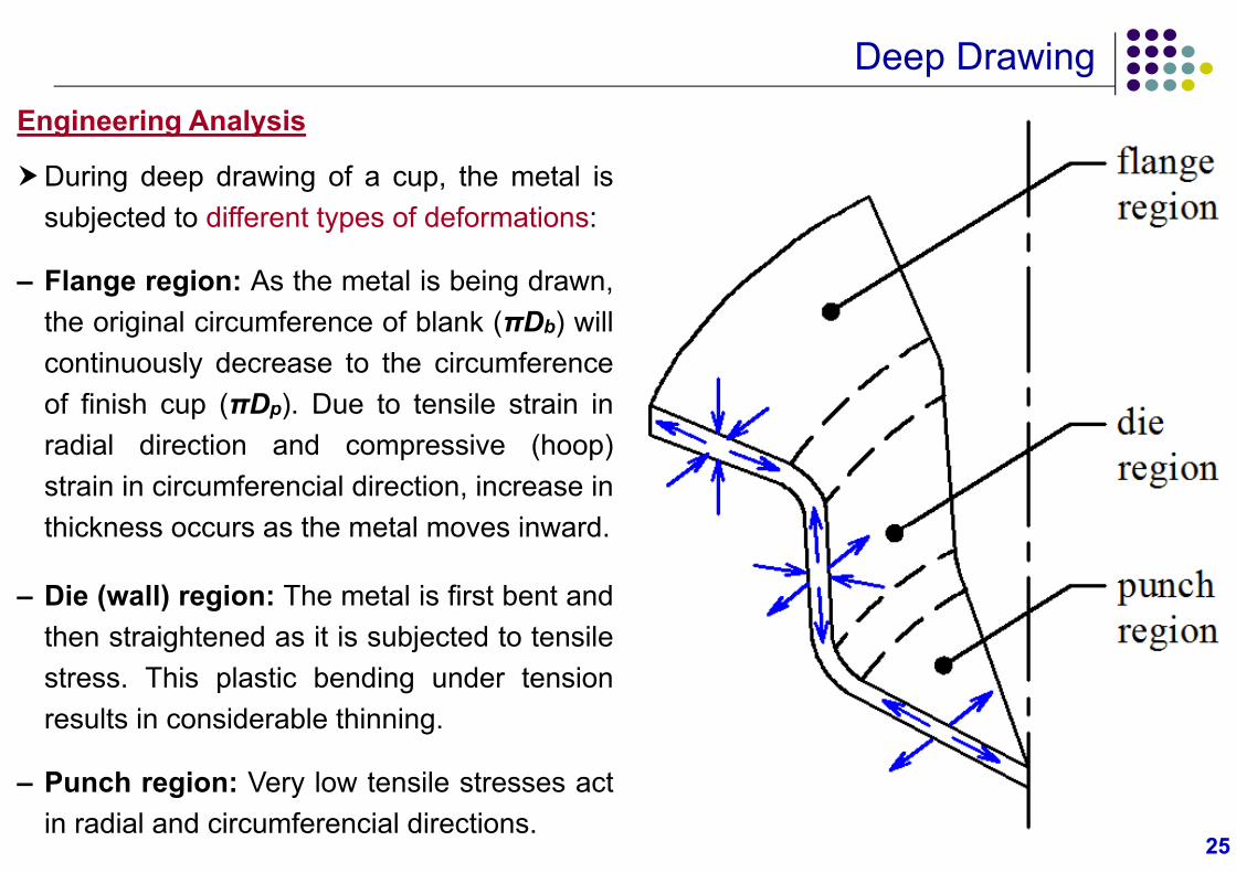
During deep drawing of a cup, the metal issubjected to different types of deformations:
– Flange region: As the metal is being drawn,the original circumference of blank (πDb) willcontinuously decrease to the circumferenceof finish cup (πDp). Due to tensile strain inradial direction and compressive (hoop)strain in circumferencial direction, increase inthickness occurs as the metal moves inward.
– Die (wall) region: The metal is first bent andthen straightened as it is subjected to tensilestress. This plastic bending under tensionresults in considerable thinning.
– Punch region: Very low tensile stresses actin radial and circumferencial directions.
2525
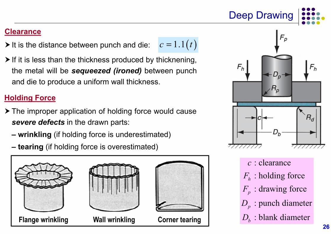
Deep DrawingClearance
It is the distance between punch and die:
If it is less than the thickness produced by thicknening,the metal will be sequeezed (ironed) between punchand die to produce a uniform wall thickness.
2626
1.1c t
Holding Force
The improper application of holding force would causesevere defects in the drawn parts:– wrinkling (if holding force is underestimated)– tearing (if holding force is overestimated)
Flange wrinkling Wall wrinkling Corner tearing
: clearance: holding force: drawing force
: punch diameter
: blank diameter
h
p
p
b
cFF
D
D
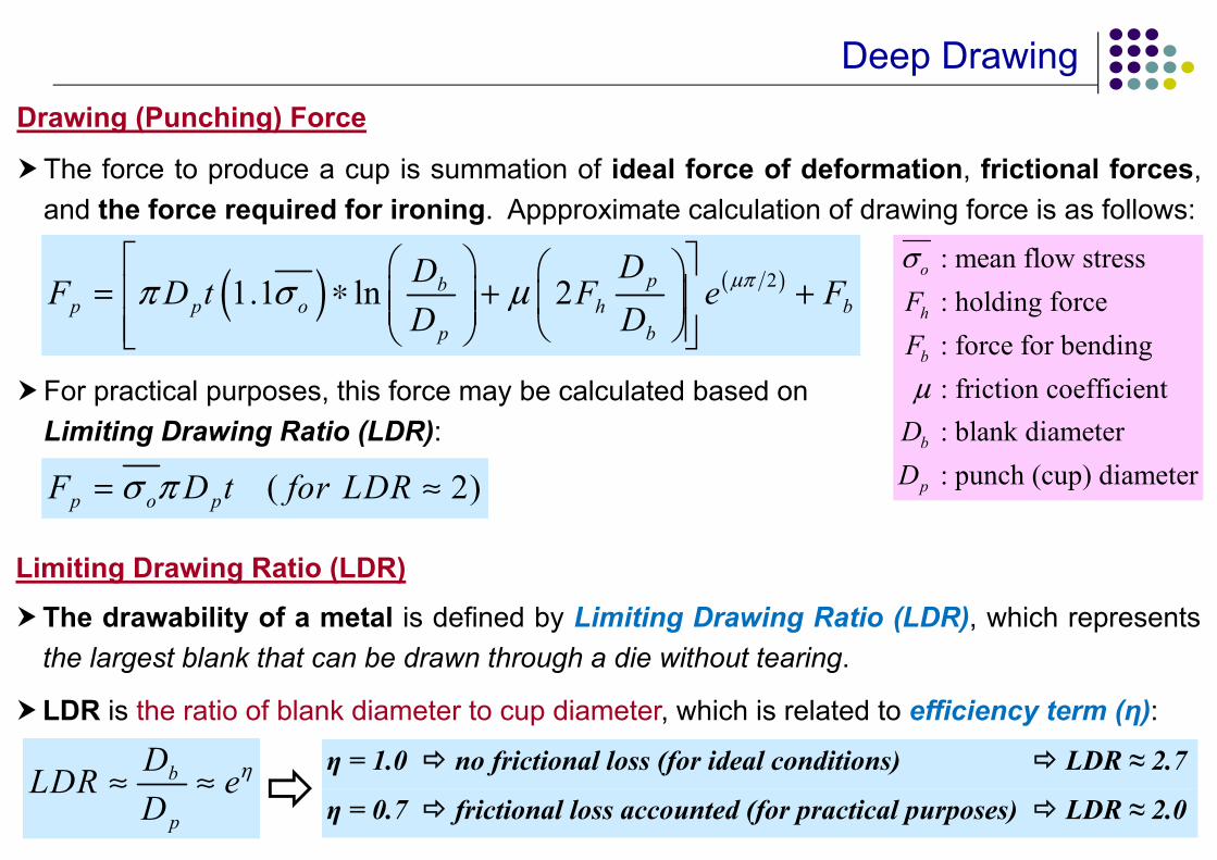
Deep DrawingDrawing (Punching) Force
The force to produce a cup is summation of ideal force of deformation, frictional forces,and the force required for ironing. Appproximate calculation of drawing force is as follows:
For practical purposes, this force may be calculated based onLimiting Drawing Ratio (LDR):
21.1 ln 2 pbp p o h b
p b
DDF D t F e FD D
Limiting Drawing Ratio (LDR)
The drawability of a metal is defined by Limiting Drawing Ratio (LDR), which representsthe largest blank that can be drawn through a die without tearing.
LDR is the ratio of blank diameter to cup diameter, which is related to efficiency term (η):
b
p
DLDR eD
( 2)p o pF D t for LDR
η = 1.0 no frictional loss (for ideal conditions) LDR ≈ 2.7
η = 0.7 frictional loss accounted (for practical purposes) LDR ≈ 2.0
: mean flow stress : holding force : force for bending: friction coefficient
: blank diameter: punch (cup) diameter
o
h
b
b
p
FF
DD
Deep Drawing
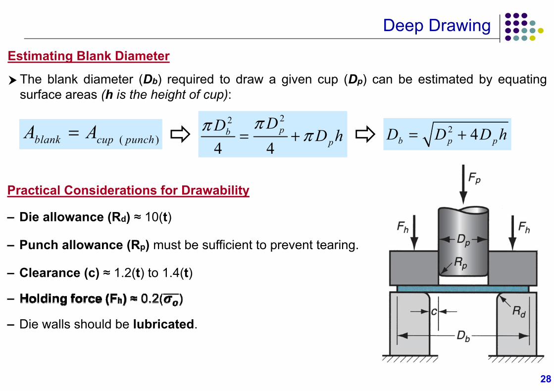
Estimating Blank Diameter
The blank diameter (Db) required to draw a given cup (Dp) can be estimated by equatingsurface areas (h is the height of cup):
Practical Considerations for Drawability
– Die allowance (Rd) ≈ 10(t)
– Punch allowance (Rp) must be sufficient to prevent tearing.
– Clearance (c) ≈ 1.2(t) to 1.4(t)
–
– Die walls should be lubricated.
( )blank cup punchA A22
4 4pb
p
DD D h 2 4b p pD D D h
28
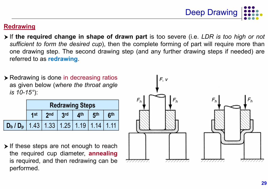
Deep DrawingRedrawing
If the required change in shape of drawn part is too severe (i.e. LDR is too high or notsufficient to form the desired cup), then the complete forming of part will require more thanone drawing step. The second drawing step (and any further drawing steps if needed) arereferred to as redrawing.
Redrawing is done in decreasing ratiosas given below (where the throat angleis 10-15°):
Redrawing Steps1st 2nd 3rd 4th 5th 6th
Db / Dp 1.43 1.33 1.25 1.19 1.14 1.11
If these steps are not enough to reachthe required cup diameter, annealingis required, and then redrawing can beperformed.
29
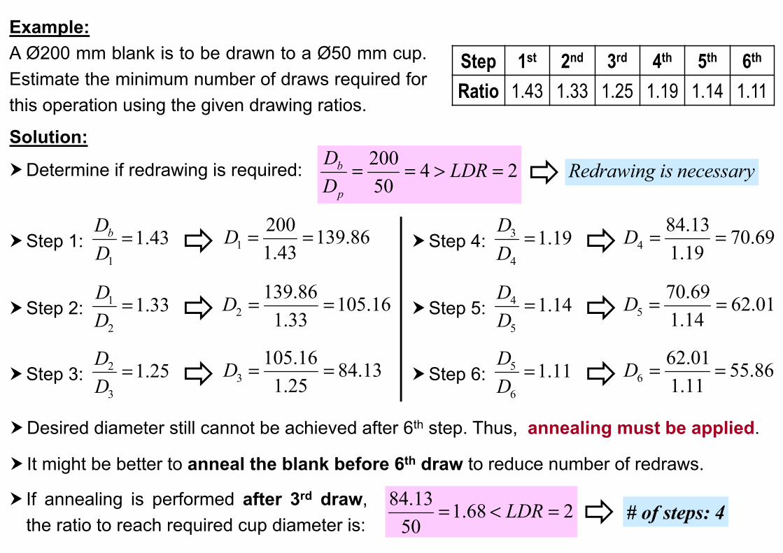
Example:A Ø200 mm blank is to be drawn to a Ø50 mm cup.Estimate the minimum number of draws required forthis operation using the given drawing ratios.
Solution:
Determine if redrawing is required: Redrawing is necessary
Step 1st 2nd 3rd 4th 5th 6th
Ratio 1.43 1.33 1.25 1.19 1.14 1.11
200 4 250
b
p
D LDRD
Step 1:1
1.43bDD
1200 139.861.43
D Step 4: 3
4
1.19DD
484.13 70.691.19
D
Step 2: 1
2
1.33DD
2139.86 105.16
1.33D Step 5: 4
5
1.14DD
570.69 62.011.14
D
Step 3: 2
3
1.25DD
3105.16 84.13
1.25D Step 6: 5
6
1.11DD
662.01 55.861.11
D
Desired diameter still cannot be achieved after 6th step. Thus, annealing must be applied.
It might be better to anneal the blank before 6th draw to reduce number of redraws.
If annealing is performed after 3rd draw,the ratio to reach required cup diameter is:
84.13 1.68 250
LDR # of steps: 4
3131
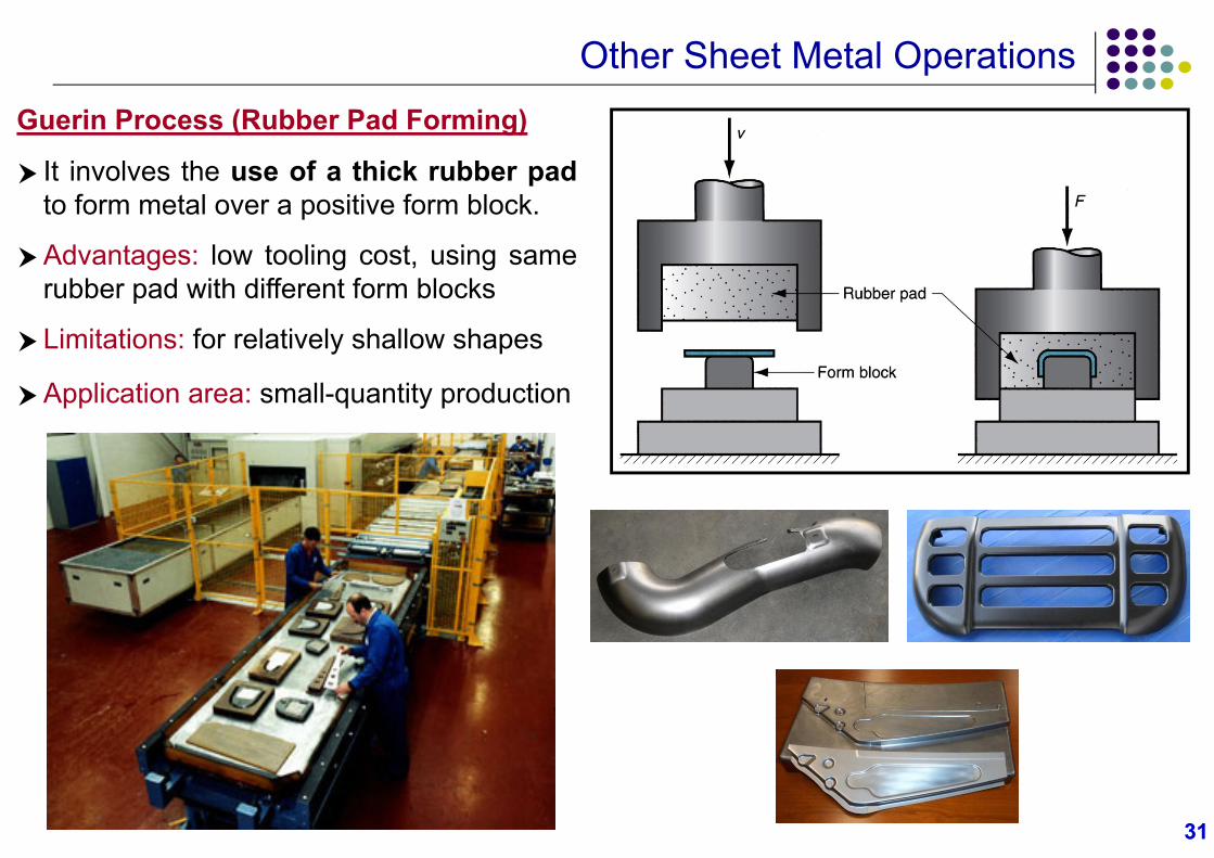
Other Sheet Metal OperationsGuerin Process (Rubber Pad Forming)
It involves the use of a thick rubber padto form metal over a positive form block.
Advantages: low tooling cost, using samerubber pad with different form blocks
Limitations: for relatively shallow shapes
Application area: small-quantity production
3232
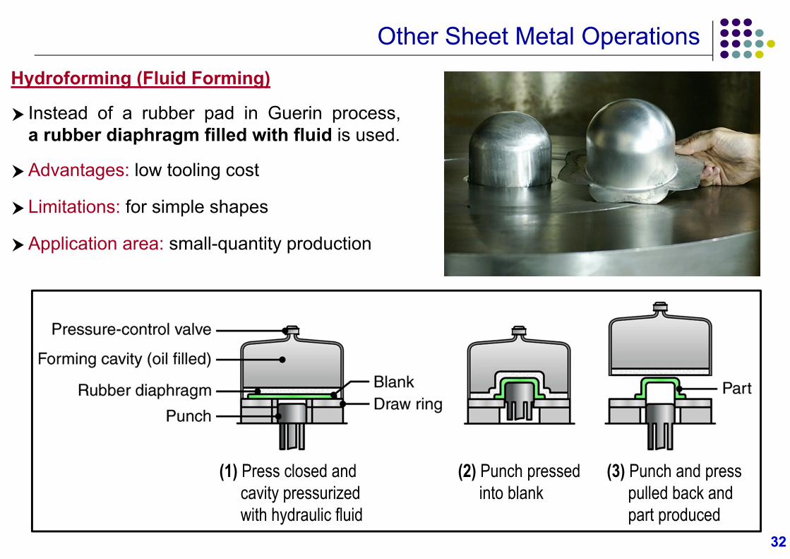
Other Sheet Metal OperationsHydroforming (Fluid Forming)
Instead of a rubber pad in Guerin process,a rubber diaphragm filled with fluid is used.
Advantages: low tooling cost
Limitations: for simple shapes
Application area: small-quantity production
(1) Press closed andcavity pressurized with hydraulic fluid
(2) Punch pressed into blank
(3) Punch and press pulled back and part produced
3333
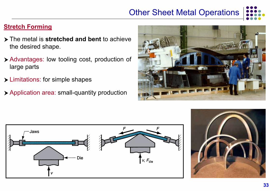
Other Sheet Metal OperationsStretch Forming
The metal is stretched and bent to achievethe desired shape.
Advantages: low tooling cost, production oflarge parts
Limitations: for simple shapes
Application area: small-quantity production
3434
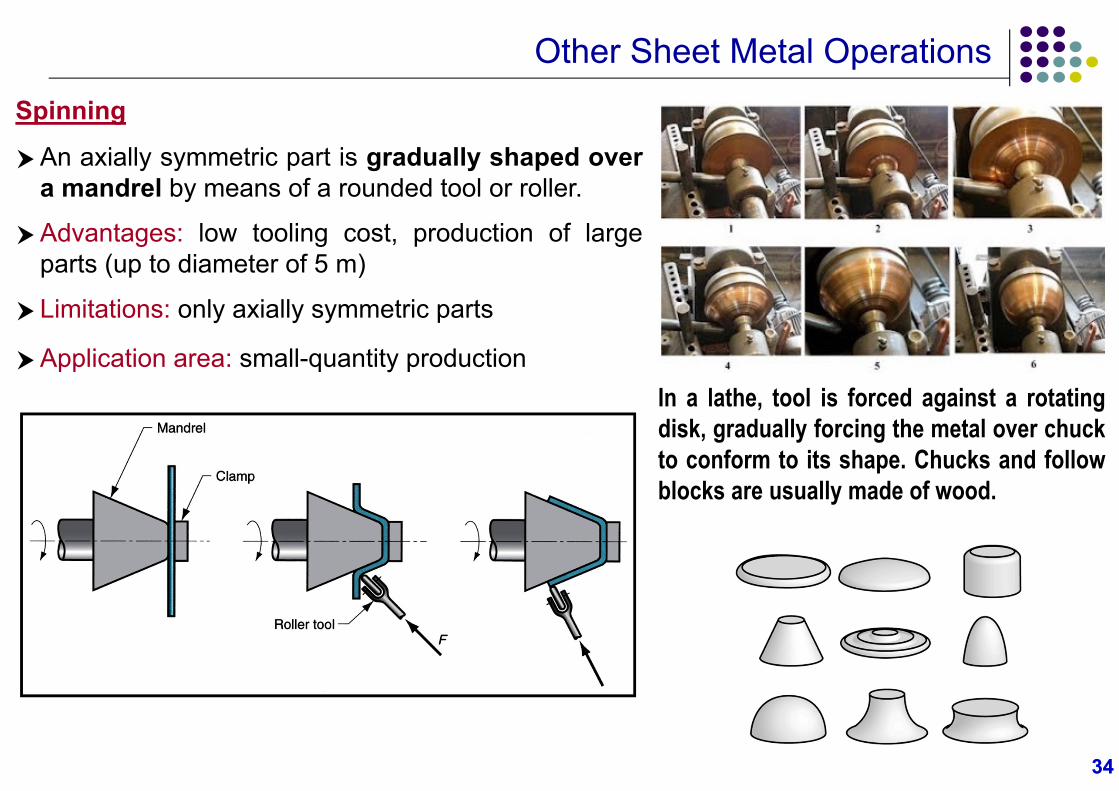
Other Sheet Metal OperationsSpinning
An axially symmetric part is gradually shaped overa mandrel by means of a rounded tool or roller.
Advantages: low tooling cost, production of largeparts (up to diameter of 5 m)
Limitations: only axially symmetric parts
Application area: small-quantity productionIn a lathe, tool is forced against a rotatingdisk, gradually forcing the metal over chuckto conform to its shape. Chucks and followblocks are usually made of wood.
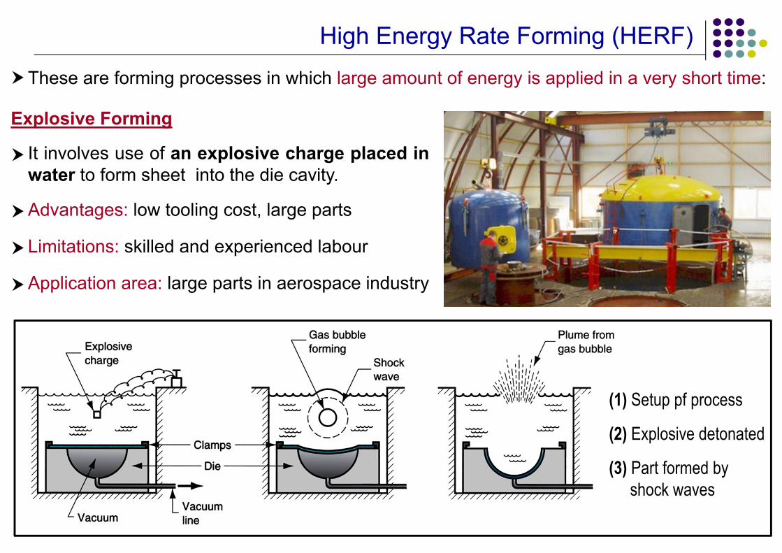
High Energy Rate Forming (HERF)
Explosive Forming
It involves use of an explosive charge placed inwater to form sheet into the die cavity.
Advantages: low tooling cost, large parts
Limitations: skilled and experienced labour
Application area: large parts in aerospace industry
These are forming processes in which large amount of energy is applied in a very short time:
(1) Setup pf process
(2) Explosive detonated
(3) Part formed by shock waves
3636
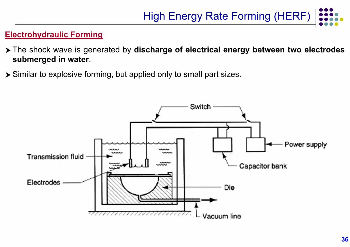
High Energy Rate Forming (HERF)Electrohydraulic Forming
The shock wave is generated by discharge of electrical energy between two electrodessubmerged in water.
Similar to explosive forming, but applied only to small part sizes.
3737
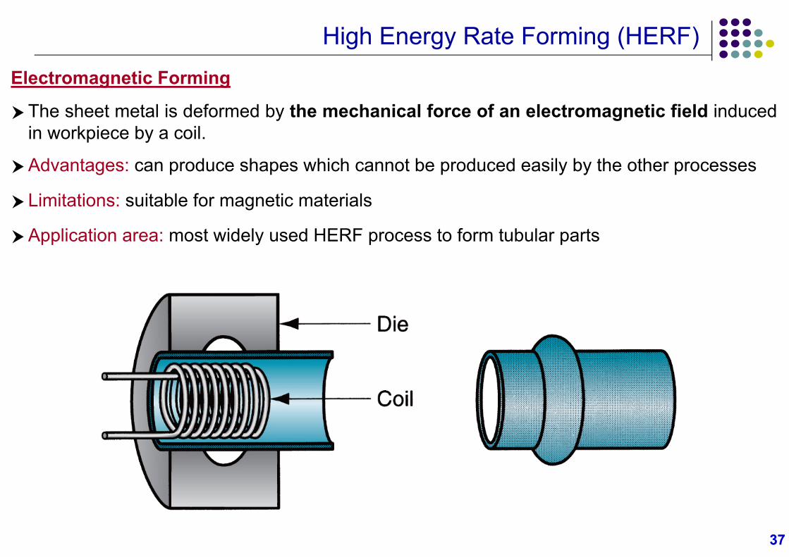
High Energy Rate Forming (HERF)Electromagnetic Forming
The sheet metal is deformed by the mechanical force of an electromagnetic field inducedin workpiece by a coil.
Advantages: can produce shapes which cannot be produced easily by the other processes
Limitations: suitable for magnetic materials
Application area: most widely used HERF process to form tubular parts