sheet metal forming process
DESCRIPTION
Sheet metal Forming Process & Methods of FormingTRANSCRIPT

Sheet Metal Forming
2.810 Fall 2002Professor Tim Gutowski
Minoan gold pendant of bees encircling the Sun, showing the use of granulation, from a tomb at Mallia, 17th century BC. In the Archaeological Museum, Iráklion, Crete.
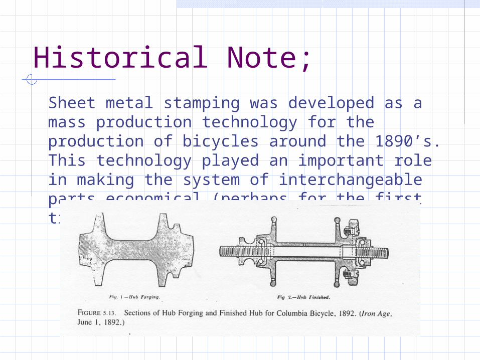
Historical Note;Sheet metal stamping was developed as a mass production technology for the production of bicycles around the 1890’s. This technology played an important role in making the system of interchangeable parts economical (perhaps for the first time).
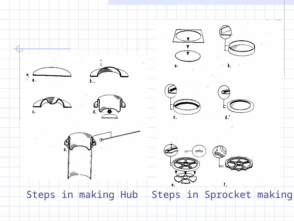
Steps in making Hub Steps in Sprocket making

Stress Strain diagram – materials selection
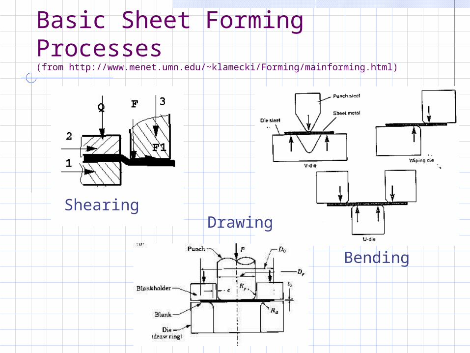
Basic Sheet Forming Processes(from http://www.menet.umn.edu/~klamecki/Forming/mainforming.html)
Shearing
Bending
Drawing
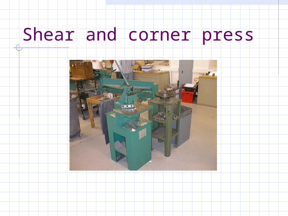
Shear and corner press

Brake press
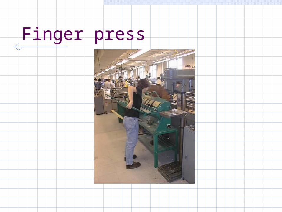
Finger press

Shearing Operation Force Requirement
Die
SheetPunch T
D
Part or slug
F = 0.7 T L (UTS)
T = Sheet ThicknessL = Total length ShearedUTS = Ultimate Tensile Strength of material

Yield Criteria
Y
Y/2
Tresca Mises
max = (2/3)1/2 Y max = (1/2) Y
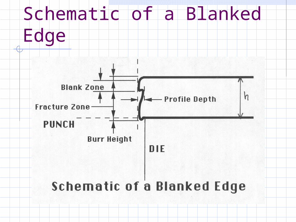
Schematic of a Blanked Edge

Bending Force Requirement
PunchWorkpiece T
Die
L
Force
T = Sheet ThicknessW = Total Width Sheared
(into the page)
L =Span lengthUTS = Ultimate Tensile Strength of material
Engineering Strain during Bending: e = 1/((2R/T) + 1)R = Bend radius
Minimum Bend radius: R = T ((50/r) – 1) r = tensile area reduction
in percent
)(2
UTSL
WTF

Stress distribution through the thickness of the part
yY
Y
-Y
h
-Y
Y
Elastic Elastic-plastic Fully plastic

Springback
•Over-bend•Bottom•Stretch
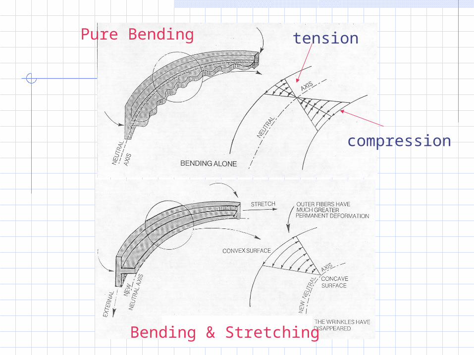
tension
compression
Pure Bending
Bending & Stretching
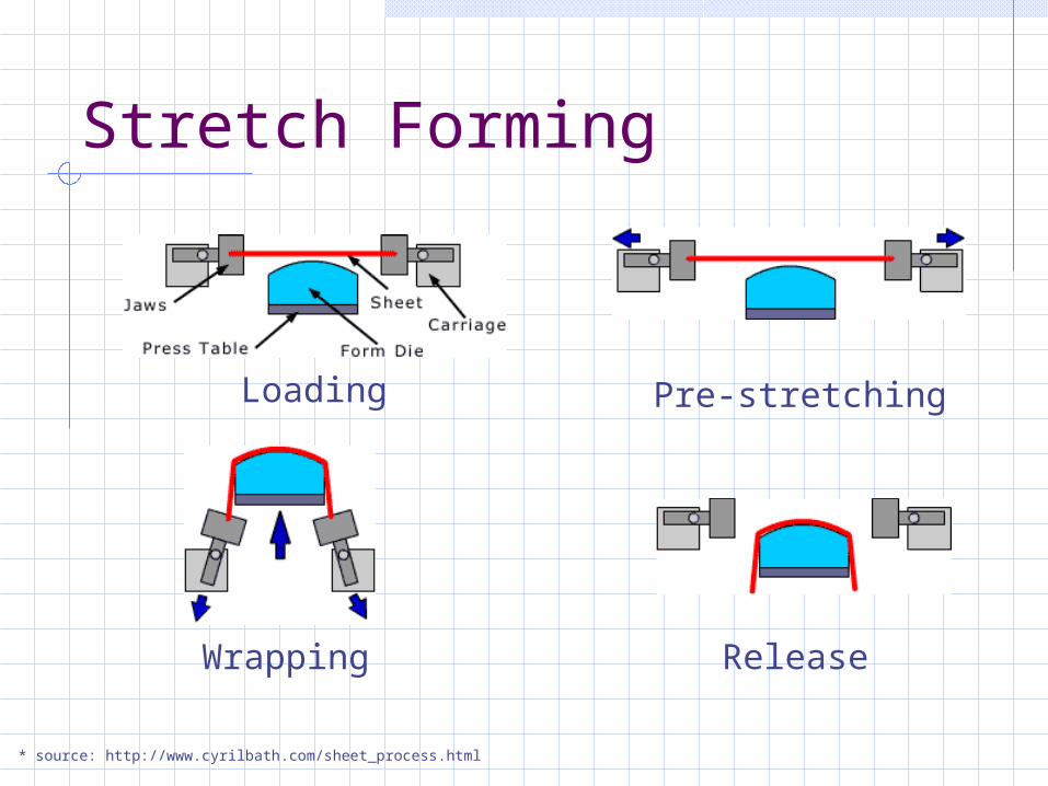
Stretch Forming
Loading Pre-stretching
Wrapping Release
* source: http://www.cyrilbath.com/sheet_process.html
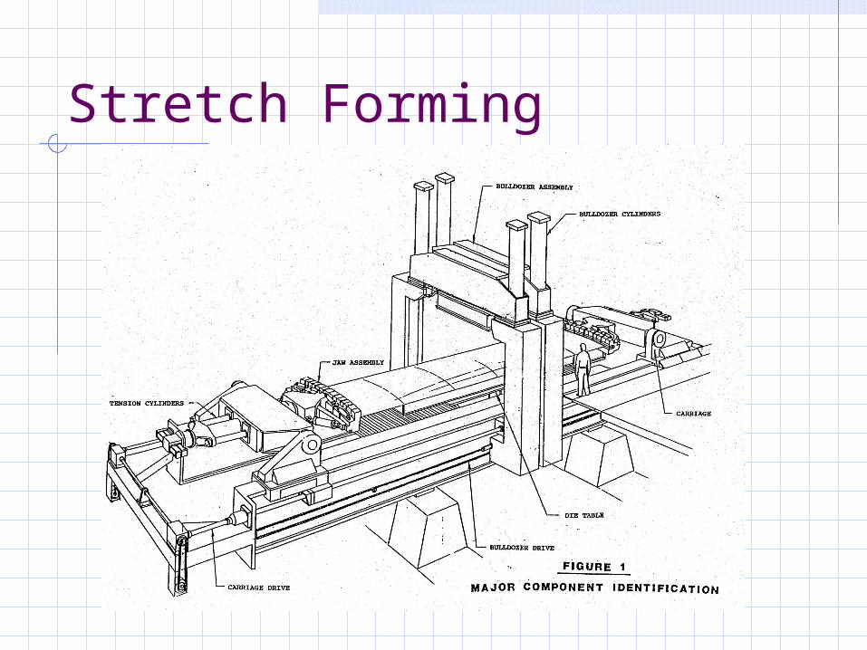
Stretch Forming

Stretch forming
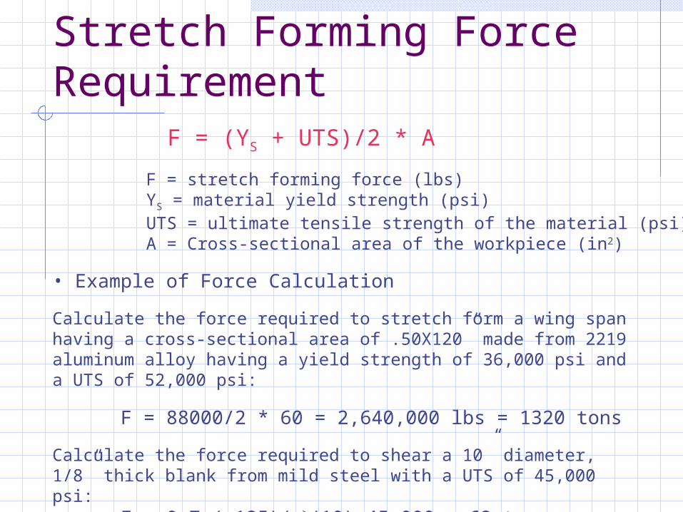
Stretch Forming Force Requirement
F = (YS + UTS)/2 * A
F = stretch forming force (lbs)YS = material yield strength (psi)UTS = ultimate tensile strength of the material (psi)A = Cross-sectional area of the workpiece (in2)
• Example of Force Calculation
Calculate the force required to stretch form a wing span having a cross-sectional area of .50X120” made from 2219 aluminum alloy having a yield strength of 36,000 psi and a UTS of 52,000 psi:
F = 88000/2 * 60 = 2,640,000 lbs = 1320 tons
Calculate the force required to shear a 10” diameter, 1/8” thick blank from mild steel with a UTS of 45,000 psi:
F = 0.7 (.125)((10) 45,000 = 62 tons
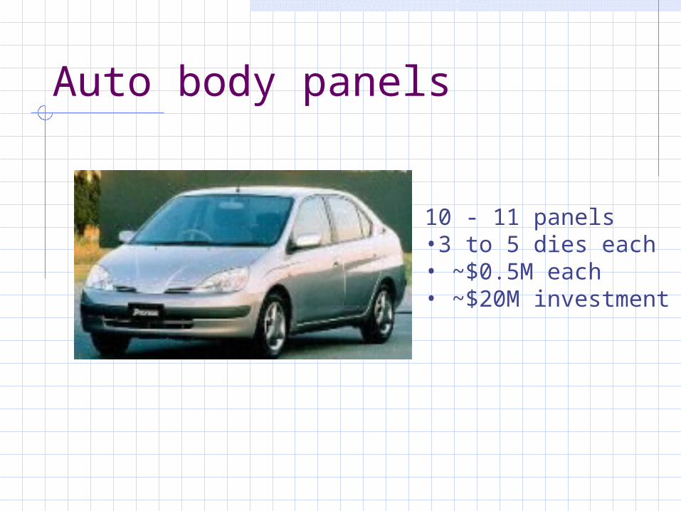
Auto body panels
10 - 11 panels•3 to 5 dies each• ~$0.5M each• ~$20M investment

Tooling for Automotive Stamping

Machines
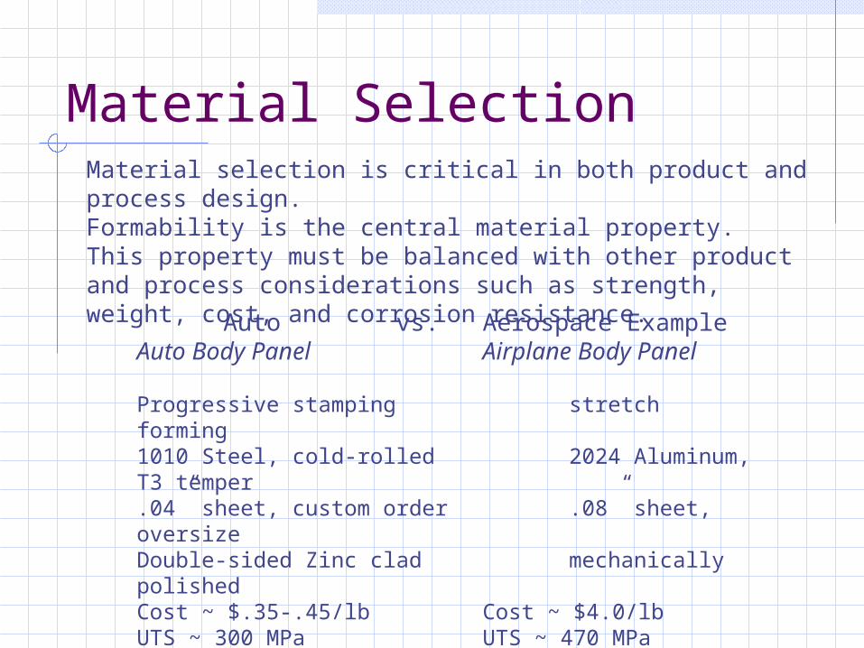
Material SelectionMaterial selection is critical in both product and process design.Formability is the central material property.This property must be balanced with other product and process considerations such as strength, weight, cost, and corrosion resistance.Auto vs. Aerospace Example
Auto Body Panel Airplane Body Panel
Progressive stamping stretch forming1010 Steel, cold-rolled 2024 Aluminum, T3 temper.04” sheet, custom order .08” sheet, oversizeDouble-sided Zinc clad mechanically polishedCost ~ $.35-.45/lb Cost ~ $4.0/lbUTS ~ 300 MPa UTS ~ 470 MPaYS ~ 185 MPa YS ~ 325 MPa Elongation ~ 42% Elongation ~ 20%n = .26 n = .16

Comparison of representative Parts: Aero and Auto
Auto AeroPart Description Body Panel Body Panel
54"X54" 54"X54"
Forming Process Progressive Stamping Stretch FormingMATERIAL
Material
1010 Steel, cold-rolled, .04" sheet, custom order double-sided Zinc clad
2024 Aluminum, T3 temper, .08" sheet,
oversize mechanically polished
Scrap 40% 20%Material Cost $0.45/lb $4.00/lbPer part $15.75 $105.00
LABORSet-up Time 1.5hr 1.0hrParts/Run 2,000 30Cycle Time 0.25 min 2.5 minTotal Labor 0.30 min 4.5 minLabor Rate** $20.00/hr $20.00/hrStretch-Form Labor Cost $0.10 $1.50
FIXEDEquipment $5,000,000 $1,000,000Tools/Dies $900,000 $45,000
(200 manhours labor)TOTAL TRANSFER COST $25 $265
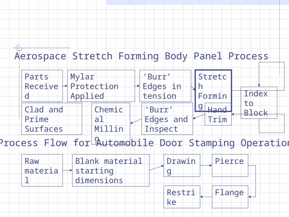
Parts Received
Mylar Protection Applied
‘Burr’ Edges in tension
Stretch Forming Index
to Block‘Burr’
Edges and Inspect
Hand Trim
Chemical Milling
Aerospace Stretch Forming Body Panel Process
Clad and Prime Surfaces
Process Flow for Automobile Door Stamping Operation
Raw material
Blank material starting dimensions
Drawing
Pierce
FlangeRestrike
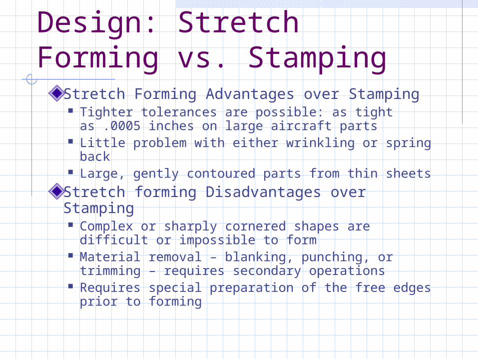
Design: Stretch Forming vs. Stamping
Stretch Forming Advantages over Stamping Tighter tolerances are possible: as tight as .0005
inches on large aircraft parts Little problem with either wrinkling or spring back Large, gently contoured parts from thin sheets
Stretch forming Disadvantages over Stamping Complex or sharply cornered shapes are difficult
or impossible to form Material removal – blanking, punching, or
trimming – requires secondary operations Requires special preparation of the free edges
prior to forming

Springback
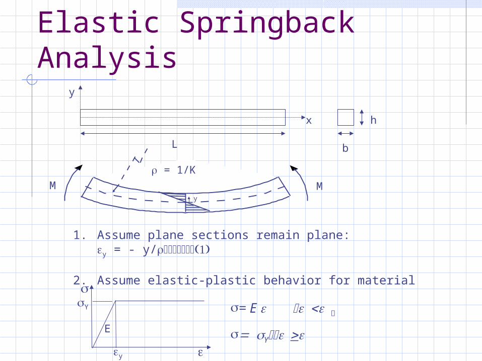
Elastic Springback Analysis
L
x
y
h
b
1. Assume plane sections remain plane:y = - y/
2. Assume elastic-plastic behavior for material
M
= 1/K
My
E
y
Y = E
Y
M
1/
EI
1/Y
MY
Loading
EI Unloading
R0R1
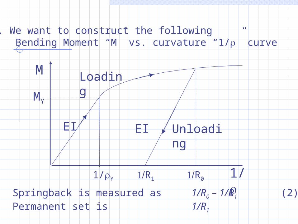
3. We want to construct the following Bending Moment “M” vs. curvature “1/” curve
Springback is measured as 1/R0 – 1/R1 (2)Permanent set is 1/R1

4. Stress distribution through the thickness of the beam
yY
Y
-Y
h
-Y
Y
Elastic Elastic-plastic Fully plastic
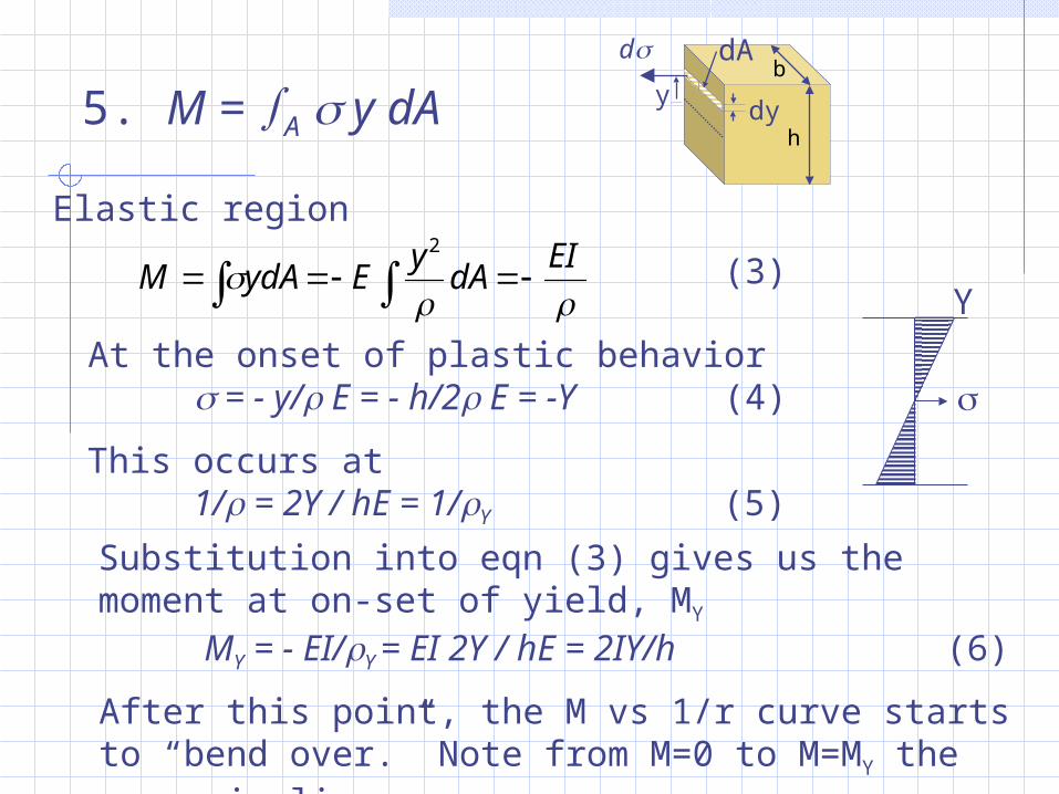
5. M = A y dA
Elastic region
At the onset of plastic behavior = - y/ E = - h/2 E = -Y (4)
Y
This occurs at 1/ = 2Y / hE = 1/Y (5)
d
y
dAb
hdy
Substitution into eqn (3) gives us the moment at on-set of yield, MY
MY = - EI/Y = EI 2Y / hE = 2IY/h (6)
After this point, the M vs 1/r curve starts to “bend over.” Note from M=0 to M=MY the curve is linear.
EI
dAy
EydAM 2
(3)
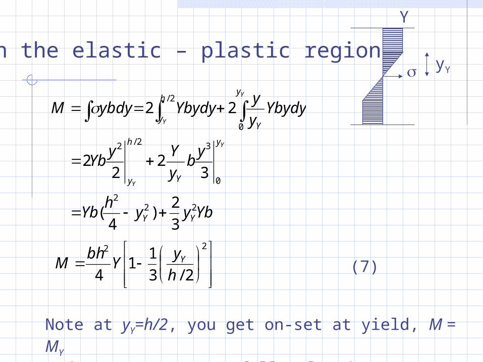
In the elastic – plastic region yY
Y
Ybyyh
Yb
yb
y
YyYb
Ybydyy
yYbydyybdyM
YY
y
Y
h
y
h
y
y
Y
Y
Y
Y
Y
222
0
32/2
2/
0
3
2)
4(
32
22
22
22
2/3
11
4 h
yY
bhM Y
Note at yY=h/2, you get on-set at yield, M = MY
And at yY=0, you get fully plastic moment, M = 3/2 MY
(7)
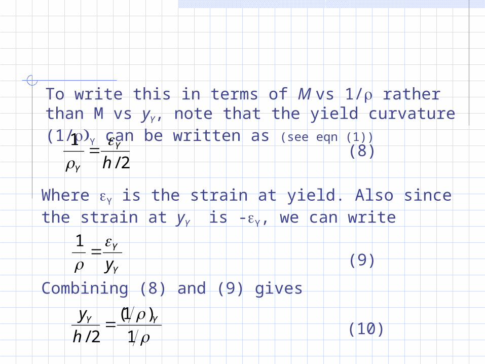
To write this in terms of M vs 1/ rather than M vs yY, note that the yield curvature (1/Y can be written as (see eqn (1))
2/
1
hY
Y
(8)
Where Y is the strain at yield. Also since the strain at yY is -Y, we can write
Y
Y
y
1
(9)
Combining (8) and (9) gives
1
)1(
2/YY
h
y (10)

Substitution into (7) gives the result we seek:
2
1
)1(
3
11
2
3
Y
YMM (11)
M
1/
EI
1/Y
MY
Loading
EI Unloading
R0R1
Eqn(11)
Elastic unloading curve
1
11
)1( R
MM
Y
Y
(12)
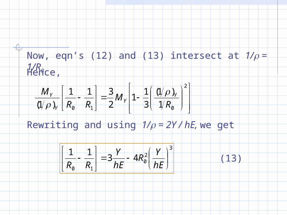
Now, eqn’s (12) and (13) intersect at 1/ = 1/R0
Hence,
2
010 1
)1(
3
11
2
311
)1( RM
RR
M YY
Y
Y
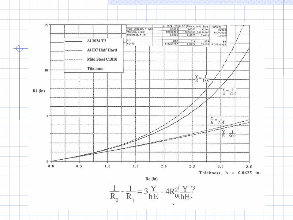
Rewriting and using 1/ = 2Y / hE, we get
320
10
4311
hE
YR
hE
Y
RR(13)

New developments
Tailored blanksBinder force controlSegmented diesQuick exchange of diesAlternative materials; cost issues
-
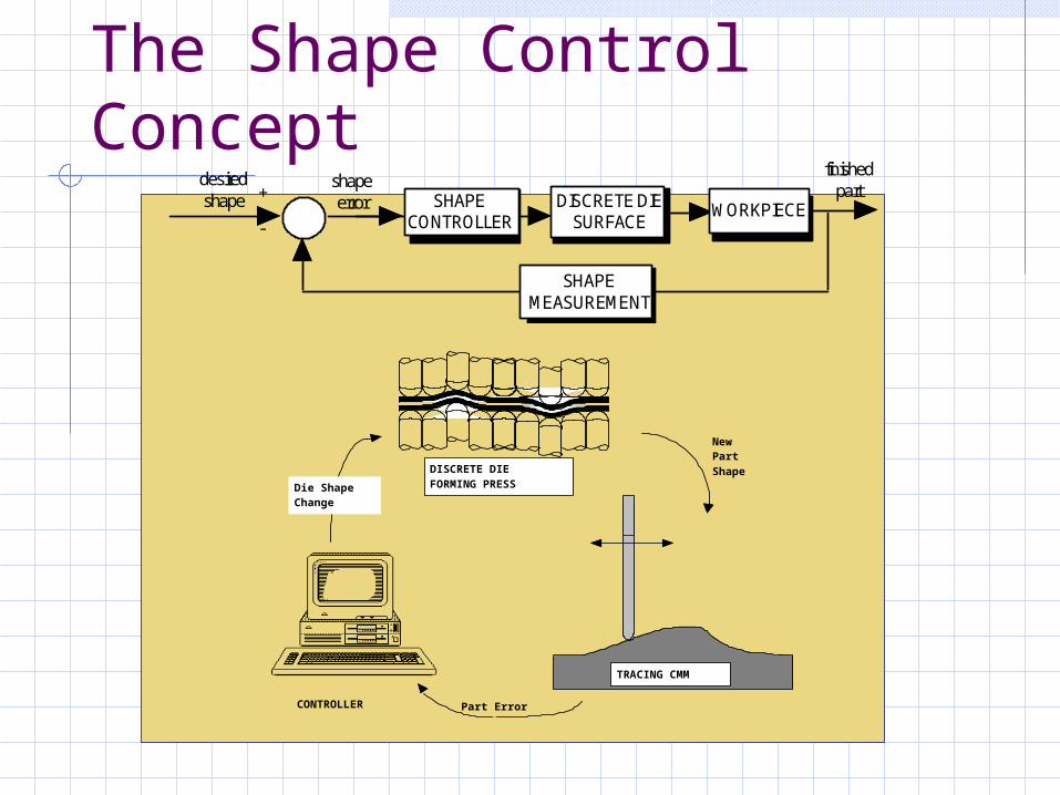
SHAPEMEASUREMENT
SHAPECONTROLLER
WORKPIECE
desiredshape +
shapeerror
finishedpartDISCRETE DIE
SURFACE
DISCRETE DIEFORMING PRESS
CONTROLLER
TRACING CMM
Part Error
Die ShapeChange
NewPartShape
The Shape Control Concept

Conventional Tooling
Tool
Pallet
Parking Lot

60 Ton Matched Discrete Die Press(Robinson et al, 1987)
Tool SetupActuators
Programmable Tool
Passive Tool
Press Motion

Cylindrical Part Error Reduction
0
10
20
30
40
50
60
P1 P2 P3 P4
PART CYCLE
0
0.2
0.4
0.6
0.8
1
1.2
1.4
1.6
RM
S E
rro
r [x
0.00
1 in
.]
MAX
RMS
SSYYSSTTEEMM EERRRROORR TTHHRREESSHHOOLLDD
MA
XIM
AL
SH
AP
E E
RR
OR
[x0
.00
1 i
n.]
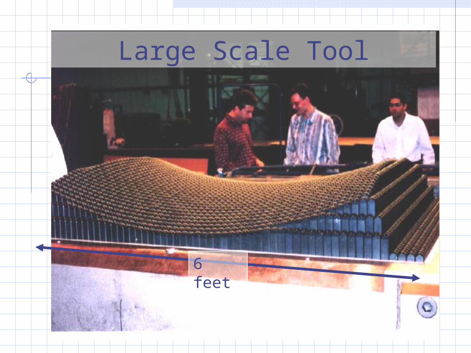
Large Scale Tool
6 feet
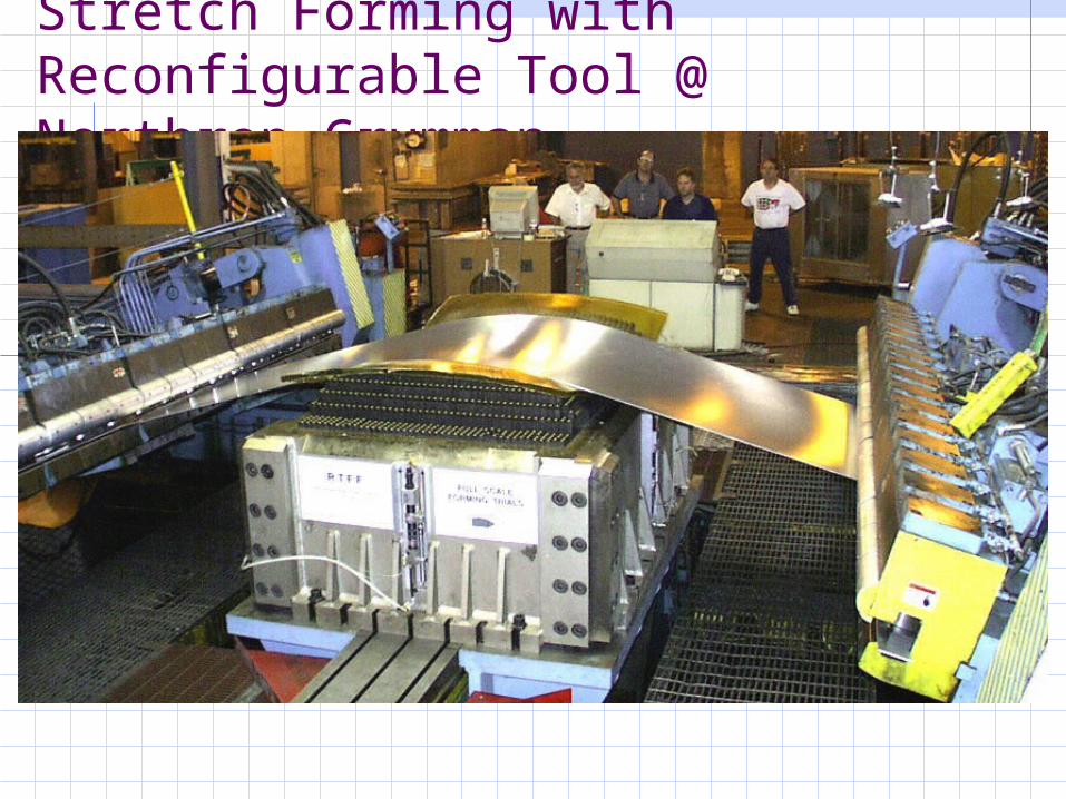
Stretch Forming with Reconfigurable Tool @ Northrop Grumman

Stamping and TPS: Quick Exchange of Dies
Ref. Shigeo Shingo, “A Revolution in Manufacturing: The SMED System” Productivity Press. 1985
•Simplify, Organize, Standardize,
•Eliminate Adjustments,
•Convert Internal to External Set-Ups
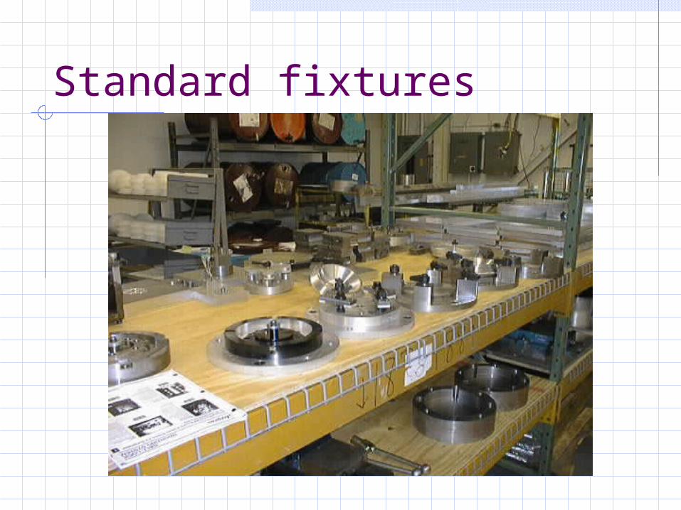
Standard fixtures

Alternative materials for auto body panels

Comparison Steel Vs SMC
$0.35/lb0.03 thick7.6 lb40% scrap$4.25 mat’l cost400/hr5 workers$18.90/hr (Union)$0.24 labor cost$5,000,000 equipment$900,000 tools$7.71 unit cost at 100,000 units
$0.65/lb.0.12 thick7.0 lb6% scrap$4.84 mat’l cost40/hr$12.50/hr (non-Union)$0.63 labor cost$1,200,000 eqipment$250,000 tools$7.75 unit cost at 100,000 units
Ref John Busch

Cost comparison between sheet steel and plastics and composites for automotive panels ref John Busch
Environment
punching Vs machining
hydraulic fluids and lubricants
scrap
energy
painting, cleaning

Steel can production at Toyo Seikan
See Appendix D; http://itri.loyola.edu/ebm/

Summary
Note on Historical Development
Materials and Basic Mechanics
Aerospace and Automotive Forming
New Developments
Environmental Issues
Solidworks and Metal Forming your
Chassis
Readings
1. “Sheet Metal Forming” Ch. 16 Kalpakjian (3rd ed.)2. “Economic Criteria for Sensible Selection of Body
Panel Materials” John Busch and Jeff Dieffenbach3. Handout from Shigeo Shingo, The SMED System4. “Steps to Building a Sheet Metal Chassis for your
2.810 Car Using Solidworks”, by Eddy Reif5. “Design for Sheetmetal Working”, Ch. 9
Boothroyd, Dewhurst and Knight