setting the standard for geophysical surveys in site investigation
TRANSCRIPT
PublicationsGeological Society, London, Engineering Geology Special
doi: 10.1144/GSL.ENG.1997.012.01.011997, v.12; p3-34.Geological Society, London, Engineering Geology Special Publications D. M. McCann, M. G. Culshaw and P. J. Fenning investigationSetting the standard for geophysical surveys in site
serviceEmail alerting
cite this article to receive free e-mail alerts when new articleshereclick
requestPermission
article to seek permission to re-use all or part of thishereclick
Subscribe
Collection Engineering Geology Special Publications or the Lyell
to subscribe to Geological Society, London,hereclick
Notes
© The Geological Society of London 2014
at University of St Andrews on August 23, 2014http://egsp.lyellcollection.org/Downloaded from at University of St Andrews on August 23, 2014http://egsp.lyellcollection.org/Downloaded from
Setting the standard for geophysical surveys in site investigation
D. M. McCann l, M. G. Culshaw 1 & P. J. Fenning 2
1 British Geological Survey, Keyworth, Nottingham, NG12 5GG, UK 2 Earth Science Systems Limited, Unit 1 Kimpton Enterprise Park, Claggy Road, Kimpton, Hertfordshire, SG4 8HP, UK
Abstract. This paper reviews the state of geophysics as applied to the engineering and environmental industries in the 1990s. The site investigation process is described emphasizing that inadequate attention is paid to understanding the ground in, or on, which structures are built. The basic principles of geophysical surveying are described, particularly the five major factors that influence the success of a geophysical survey: depth of penetration, vertical and lateral resolution, contrast in physical properties, signal to noise ratio and existing information about the site. The main surface, downhole and crosshole geophysical methods used in engineering and environmental investigations are discussed and illustrated with brief case histories from the literature. The integration of geophysical surveys into the site investigation process is described and a new procedure for the designing, commissioning and carrying out of a successful geophysical survey is presented. The underlying reasons why geophysics is perceived as 'not working,' are identified as a lack of understanding of both geological variability and geophysical methods on the part of the engineer and of engineering design and practice on the part of the geophysicist.
Site investigation is defined as the whole of the process by which information is gathered on the ground as part of the design and construction of civil engineering structures both on and within the ground. The tradi- tional approach to site investigation is based on the use of trial pits and boreholes but in many cases a large number may be required to achieve a sample density that is statistically valid to ensure that small but significant targets within the ground are located.
In recent years concern has been expressed that inadequate expenditure has been made at the site investigation stage of many civil engineering construc- tion projects and significant losses have been incurred at the later stages of many projects as a result of unforseen ground conditions. Littlejohn (1991) in particular draws attention to the importance of the site investigation process and points out the following:
�9 In civil engineering projects the largest element of technical and financial risk usually lies in the ground.
�9 The ground is a vital element of all structures which rest on or in it and there is no other element about which less is known.
�9 Insufficient attention is given to desk studies to provide valuable information at low cost.
Littlejohn (1991) expressed the view that without a properly procured, supervised and interpreted site investigation the hazards of the ground cannot be known and emphasized the importance of a comprehensive
and well-planned investigation for each construction. The results of inadequate site investigations can be observed in the following statistics quoted by Littlejohn (1991):
�9 A statistical review of 5000 industrial building projects by the National Economic Development Office (NEDO) has shown that about half the projects overran by one month or more. In a representative group of 56 case study projects, 37% suffered delays due to ground problems.
�9 In the commercial building sector, NEDO found that from an analysis of 8000 projects one third overran by more than a month; a further one third overran by up to a month. In a representative group of 60 on-site case studies, 50% suffered delays due to unforseen ground conditions.
�9 The National House Building Council (NHBC) pays out on claims having a total value of between s and s each year and of these over 50% are related to geotechnical problems.
�9 On 10 large highway construction projects Transport and Road Research Laboratory (TRRL) observed that the final cost was on average 35% greater than the tendered sum and half of this increase was due to inadequate planning of ground investigation or poor interpretation of the results.
�9 In 1989 the National Audit Office (NAO) expressed concern at extra work costing s due to geotech- nical problems on eight road and six bridge projects.
From McCann, D. M., Eddleston, M., Fenning, P. J. & Reeves, G. M. (eds), 1997, Modern Geophysics in Engineering Geology. Geological Society Engineering Geology Special Publication No. 12, pp. 3-34.
at University of St Andrews on August 23, 2014http://egsp.lyellcollection.org/Downloaded from
4 D.M. McCANN ET AL.
As a result of the concern expressed on the general shortcomings of current site investigation practice the Institution of Civil Engineers initiated the Site Investi- gation Steering Group (SISG) under the chairmanship of Professor Littlejohn with a view to providing a single national specification for site investigation with appro- priate guidance notes for its implementation in the construction industry. The SISG Report was published in 1993 and contains a wealth of knowledge from engineers and scientists from many organizations who specify or are involved in site investigation as part of their responsibilities.
Further guidelines are given in BS 5930 - the Code of Practice for Site Investigation, which was published in 1981 by the British Standards Institution. This code of practice is currently being updated by the BS I and it is anticipated that the revised document will be published in 1997. In conjunction with these two major docu- ments on site investigation practice the Engineering Group of the Geological Society have published a number of Working Party Reports on various specialist areas of engineering geology in site investigation. These include reports on Engineering Geological Mapping, Rock Mass Assessment, Aggregates, etc. The Construc- tion Industry Research and Information Association (CIRIA) also publish a range of reports highlighting other important areas of site investigation, which gen- erally expand the information available in BS 5930 and Anon (1993).
The current Code of Practice for Site Investigation (BS 5930) does contain a section on geophysical methods and their application to site investigation. This contribution to BS 5930 was prepared at a time when the improvements in both equipment and inter- pretational procedures were in a transitional state. Thus, the text summarizes how geophysical surveying con- tributed to site investigation at the end of the 1970s and the writer did not have the scope in the document, which merely described current operational practices, to con- sider new developments at that time or attempt to visualize the future. The recent revision of the Code of Practice gave an opportunity to trace the development of geophysical surveying during the 1980s and introduce new methods that are currently being developed.
The information in BS 5930 on geophysical methods was augmented by the publication of the Geological Society Engineering Group Working Party Report on Engineering Geophysics (Anon 1988a) which described the considerable improvement in geophysical surveying practice that took place during the 1980s. This report, too, is currently being revised and updated to include the significant changes in geophysical surveying methods that have taken place since 1988.
Geophysical surveying methods clearly have a role in the site investigation process but all too often they are used to provide discrete information on specific pro- blems rather than as an integral part of the overall
programme. Hence, in this paper the fundamental prin- ciples of geophysical methods are considered in some detail with a view to establishing a definitive role for them in the site investigation process. Part of this role must be the setting of agreed standards and guidelines both for the execution of each surveying method in the field and the interpretation of the geophysical data obtained as an integral part of the investigation programme. The involvement of the geophysicist as an essential part of the site investigation team has been long delayed on the majority of major civil engineering projects in Britain.
The site investigation process
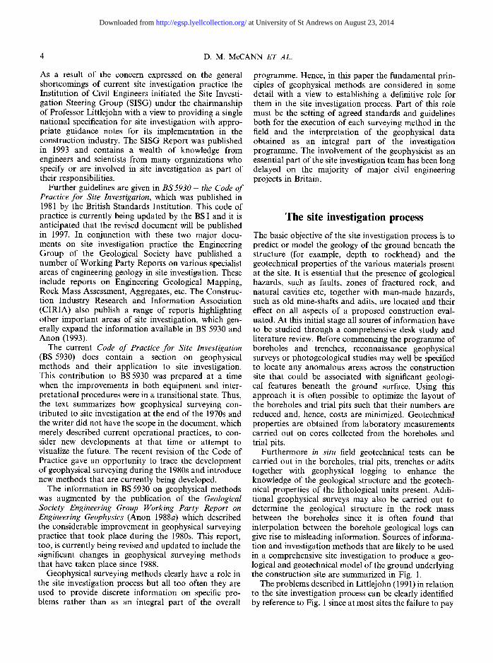
The basic objective of the site investigation process is to predict or model the geology of the ground beneath the structure (for example, depth to rockhead) and the geotechnical properties of the various materials present at the site. It is essential that the presence of geological hazards, such as faults, zones of fractured rock, and natural cavities etc, together with man-made hazards, such as old mine-shafts and adits, are located and their effect on all aspects of a proposed construction eval- uated. At this initial stage all soures of information have to be studied through a comprehensive desk study and literature review. Before commencing the programme of boreholes and trenches, reconnaissance geophysical surveys or photogeological studies may well be specified to locate any anomalous areas across the construction site that could be associated with significant geologi- cal features beneath the ground surface. Using this approach it is often possible to optimize the layout of the boreholes and trial pits such that their numbers are reduced and, hence, costs are minimized. Geotechnical properties are obtained from laboratory measurements carried out on cores collected from the boreholes and trial pits.
Furthermore in situ field geotechnical tests can be carried out in the boreholes, trial pits, trenches or adits together with geophysical logging to enhance the knowledge of the geological structure and the geotech- nical properties of the lithological units present. Addi- tional geophysical surveys may also be carried out to determine the geological structure in the rock mass between the boreholes since it is often found that interpolation between the borehole geological logs can give rise to misleading information. Sources of informa- tion and investigation methods that are likely to be used in a comprehensive site investigation to produce a geo- logical and geotechnical model of the ground underlying the construction site are summarized in Fig. 1.
The problems described in Littlejohn (1991) in relation to the site investigation process can be clearly identified by reference to Fig. 1 since at most sites the failure to pay
at University of St Andrews on August 23, 2014http://egsp.lyellcollection.org/Downloaded from
GEOPHYSICAL SURVEYS 5
Methods of the Future
rial remote sensing Geophysics~ _
Present M.thods ~ ~ Past Date
Borehol.s t SITE INVESTIGATION I Histericai records
Logging and sampling ~truoture [ pr0peKles ~ Published geological information
In situ geotechnical testing Published
geetechnical and Laboratory testing of hydrogeologlcal samples information
Fig. 1. Sources of information and investigation methods likely to be used in a comprehensive site investigation to produce a geological and geotechnical ground model.
adequate attention to the desk study, the field survey and the laboratory testing programme inevitably leads to a lack of knowledge of the geological materials present on the site and their geotechnical properties. In addition, while attempts might have been made to enhance the information available with a geophysical survey, it is often found that such surveys involve the use of inappropriate methods that do little to provide the desired geological information.
On a normal site investigation an initial desk study is carried out by engineers and planners, who collate all the available relevant information. This usually involves a geological appraisal in which local geological maps, photographs, old Ordnance Survey maps, the proceed- ings of local geological and archaeological societies (newspapers, museums) are collected and examined. Unfortunately, as reported by Howland (1991) there is no legal requirement in Britain for details of shallow site investigation boreholes to be filed at the National Geosciences Data Centre(NGDC) of the British Geolo- gical Survey (BGS) at Keyworth in Nottinghamshire. Existing legislation requires that details of boreholes over 100 feet in depth for mineral exploration and over 50 feet in depth for water must be notified to BGS. The most valuable information may well be lost to the engineer or planner, who checks with BGS for available borehole information only to find that what is needed has not been filed in the NGDC.
In normal circumstances the site investigation bore- holes or trial pits may well be positioned on a grid basis or a specific site or at regular intervals along a linear route. Some attempt would be made to concentrate more boreholes in areas where geological problems or hazards are likely to be located. The difficulty with this
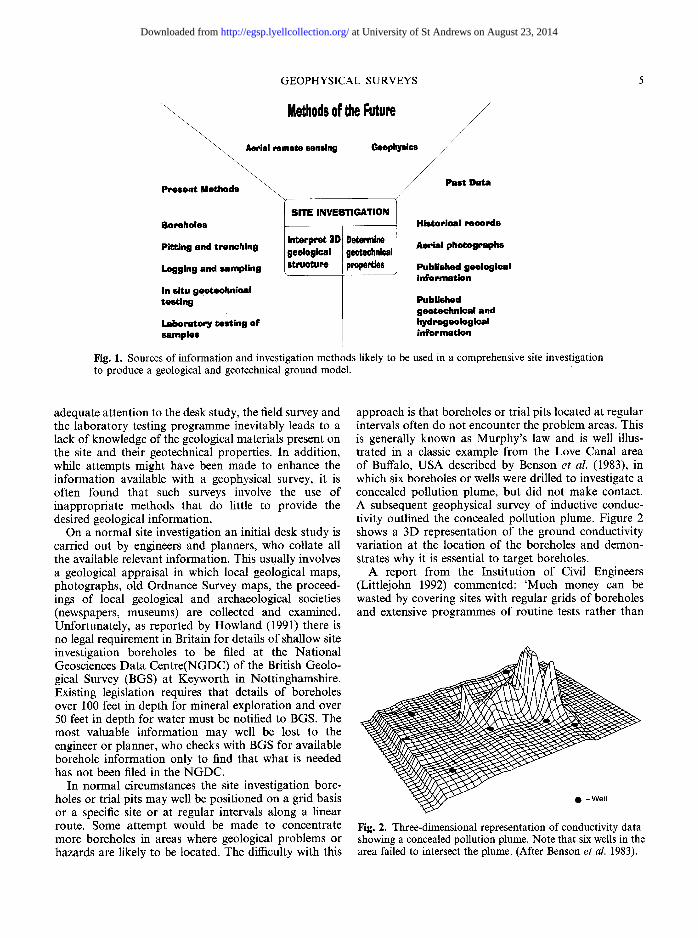
approach is that boreholes or trial pits located at regular intervals often do not encounter the problem areas. This is generally known as Murphy's law and is well illus- trated in a classic example from the Love Canal area of Buffalo, USA described by Benson et al. (1983), in which six boreholes or wells were drilled to investigate a concealed pollution plume, but did not make contact. A subsequent geophysical survey of inductive conduc- tivity outlined the concealed pollution plume. Figure 2 shows a 3D representation of the ground conductivity variation at the location of the boreholes and demon- strates why it is essential to target boreholes.
A report from the Institution of Civil Engineers (Littlejohn 1992) commented: 'Much money can be wasted by covering sites with regular grids of boreholes and extensive programmes of routine tests rather than
Fig. 2. Three-dimensional representation of conductivity data showing a concealed pollution plume. Note that six wells in the area failed to intersect the plume. (After Benson et al. 1983).
at University of St Andrews on August 23, 2014http://egsp.lyellcollection.org/Downloaded from
6 D.M. McCANN ET AL.
targeting the investigation towards areas where informa- tion is required and by using more appropriate investi- gation methods'.
Thus the engineer needs assistance in targeting the boreholes and trial pits in the areas of potential sub- surface problems. These problems have previously been encountered in the routing of hydrocarbon product supply lines for the petroleum industry and have often been solved, both on land and offshore, with the use of non-invasive surface geophysical surveys. White (1986) referred to the experience of the water industry in utiliz- ing geophysical techniques to locate boreholes for water supply worldwide over many years.
The routine use of grids of boreholes is put into per- spective by Hobson (1992) who estimated the probability of funding an area of 10 m 2 of badly contaminated land based on the minimum number of sampling points for various site areas quoted by BS I DD175 (Anon 1988b). His results are given in Table 1 and they demonstrate that the chance of finding small isolated areas of contamina- tion by random sampling is very small, as observed by
Table 1. Probability of finding an area of lOm 2 based on the minimum number of sampling points for various site areas quoted by British Standards Institution DD175 (after Hobson 1992)
Area of site Number of (hectares) sampling points
Probability of finding a contaminated area of 10 m 2
0.5 15 3% 1.0 25 2.5% 5.0 85 1.7%
Benson et al. (1983). While Hobson's statistical approach is not strictly valid for non-random distributive methods, such as grid sampling, such methods do not have a significantly better chance of finding deposits of con- taminated material.
The difficulty of understanding the ground conditions at a construction site has its origin, in part, in the way that geological knowledge advances. Geological map- ping has been carried out in Britain since the late 18th
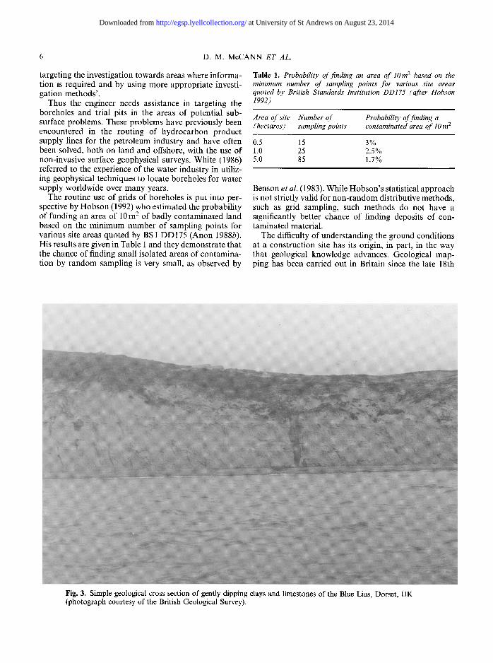
Fig. 3. Simple geological cross section of gently dipping clays and limestones of the Blue Lias, Dorset, UK (photograph courtesy of the British Geological Survey).
at University of St Andrews on August 23, 2014http://egsp.lyellcollection.org/Downloaded from
GEOPHYSICAL SURVEYS 7
century when the canal network was constructed. Two hundred years have elapsed since that time but the process of updating British geological maps continues at the BGS. The reason for this is not difficult to under- stand since the geologist has to interpret information from boreholes, trenches and various exposures o frocks seen in cuttings, quarries and cliff sections. The geological map and the geological cross sections produced from these data are, thus, models constructed by the geologist whose relationship to the true geological structure below the ground surface is a function of the available data and the ability of the geologist to interpret them.
However, the geological structure in many areas is extremely complex and great difficulty is often encoun- tered in proposing a geological model which is really representative of the in situ ground conditions. For example, the cliff section shown in Fig. 3 is a good exam- ple of a simple geological cross-section of gently dipping rocks of the Blue Lias of Jurassic age and its interpreta- tion in geological terms is relatively straightforward since only a few boreholes would be needed to predict
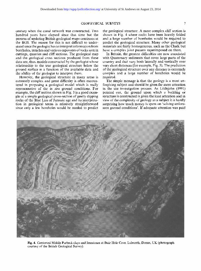
the geological structure. A more complex cliff section is shown in Fig. 4 where rocks have been heavily folded and a large number of boreholes would be required to predict the geological structure. Many other geological materials are fairly homogeneous, such as the Chalk but have a complex joint pattern superimposed on them.
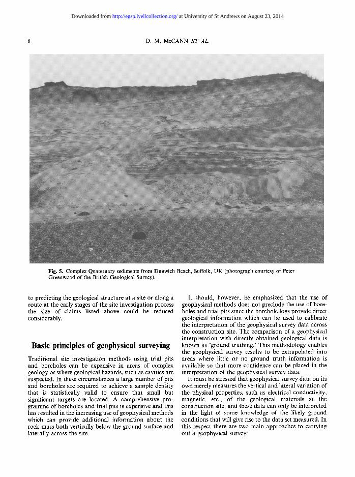
In Britain, the greatest difficulties are now associated with Quaternary sediments that cover large parts of the country and that vary both laterally and vertically over very short distances (for example, Fig. 5). The prediction of the geological structure over any distance is extremely complex and a large number of boreholes would be required.
The simple message is that the geology is a most un- forgiving subject and should be given far more attention in the site investigation process. As Littlejohn (1991) pointed out, the ground upon which a building or structure is constructed is given the least attention and in view of the complexity of geology as a subject it is hardly surprising how much money is spent on 'solving unfore- seen ground conditions'. If adequate attention was paid
Fig. 4. Contorted Middle Purbeck clays and limestones at Stair Hole Cove, Lulworth, Dorset, UK (photograph courtesy of the British Geological Survey).
at University of St Andrews on August 23, 2014http://egsp.lyellcollection.org/Downloaded from
8 D.M. McCANN E T AL.
Fig. 5. Complex Quaternary sediments from Dunwich Beach, Suffolk, UK (photograph courtesy of Peter Greenwood of the British Geological Survey).
to predicting the geological structure at a site or along a route at the early stages of the site investigation process the size of claims listed above could be reduced considerably.
Basic principles of geophysical surveying
Traditional site investigation methods using trial pits and boreholes can be expensive in areas of complex geology or where geological hazards, such as cavities are suspected. In these circumstances a large number of pits and boreholes are required to achieve a sample density that is statistically valid to ensure that small but significant targets are located. A comprehensive pro- gramme of boreholes and trial pits is expensive and this has resulted in the increasing use of geophysical methods which can provide additional information about the rock mass both vertically below the ground surface and laterally across the site.
It should, however, be emphasized that the use of geophysical methods does not preclude the use of bore- holes and trial pits since the borehole logs provide direct geological information which can be used to calibrate the interpretation of the geophysical survey data across the construction site. The comparison of a geophysical interpretation with directly obtained geological data is known as 'ground truthing.' This methodology enables the geophysical survey results to be extrapolated into areas where little or no ground truth information is available so that more confidence can be placed in the interpretation of the geophysical survey data.
It must be stressed that geophysical survey data on its own merely measures the vertical and lateral variation of the physical properties, such as electrical conductivity, magnetic, etc., of the geological materials at the construction site, and these data can only be interpreted in the light of some knowledge of the likely ground conditions that will give rise to the data set measured. In this respect there are two main approaches to carrying out a geophysical survey:
at University of St Andrews on August 23, 2014http://egsp.lyellcollection.org/Downloaded from
GEOPHYSICAL SURVEYS 9
�9 Measurement of a physical property, such as electrical conductivity on a grid basis over the ground surface. Contouring of this data will locate anomalous zones, which may be associated with buried objects, such as metal barrels, or changes in the groundwater compo- sition. Further investigation of the anomalous areas is required, unless historical information exists which indicates the likely cause of geophysical anomaly.
�9 Measurement of a physical property along a detailed horizontal profile, such that details of the vertical variation of that property are determined. In this case the geophysicist attempts to produce a mathematical model of the geological structure or distribution of landfill material which will give rise to the measured geophysical data set. Again, the accuracy of the model is largely dependent on the ground truth information that is available either from historical sources or from boreholes and trial pits.
It is important to differentiate between these two approaches to geophysical surveying since the produc- tion of a simple contoured geophysical map which identifies anomalous ground conditions is far quicker and less expensive to carry out than the more detailed survey which gives rise to a model of both the vertical and lateral geological structure in three dimensions. It is probable that the lack of appreciation of this one factor has resulted in much of the bad press received in many areas where geophysical methods have been applied, since the cost of obtaining the complete 3D model of the geological structure or landfill distribution on a site can be four to five times greater than that for producing a simple contoured geophysical map. As in all other fields the final objective of the geophysical survey must be clearly specified such that it can be designed and costed appropriately to achieve the required objective.
There are many geophysical techniques, each based on different theoretical principles, and producing as a result different sets of information regarding the physical properties of the rock mass. These properties, such as compressional and shear wave velocities, electrical resistivity, etc., have to be interpreted in terms of the geological structure or engineering properties. Inevita- bly, this interpretation involves some degree of assump- tion about the geological structure, and the use of calibration boreholes is an essential feature of most geo- physical surveys. Furthermore, many geological prob- lems will be best studied by a particular geophysical method, depending upon which physical properties of the sub-surface material offer the best chance of being reliably determined.
There are five major factors that need to be considered in the design of a geophysical survey:
(1) the required depth of penetration into the geologi- cal formation or anomalous material;
(2) the vertical and lateral resolution required for the anticipated targets;
(3) the contrast in physical properties between the target and its surroundings;
(4) signal to noise ratio for the physical property measured at the site under investigation;
(5) historical information from previous investigations at the site, geological and topographical maps, knowledge of tipping history or past land use etc.
Careful application of all the above factors to the design of a geophysical survey should result in a specifi- cation which either achieves the desired objectives or, more importantly, recommends an alternative approach if no geophysical surveying method is deemed appro- priate to the solution of the problem specified. Some examples of the importance of these factors are pre- sented below; the principles of the different methods referred to are described later in the text.
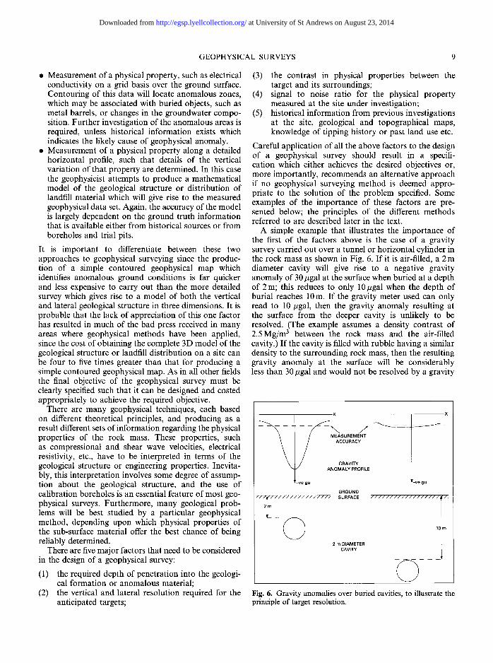
A simple example that illustrates the importance of the first of the factors above is the case of a gravity survey carried out over a tunnel or horizontal cylinder in the rock mass as shown in Fig. 6. If it is air-filled, a 2 m diameter cavity will give rise to a negative gravity anomaly of 30 #gal at the surface when buried at a depth of 2m; this reduces to only 10#gal when the depth of burial reaches 10m. If the gravity meter used can only read to 10 #gal, then the gravity anomaly resulting at the surface from the deeper cavity is unlikely to be resolved. (The example assumes a density contrast of 2.5Mg/m 3 between the rock mass and the air-filled cavity.) If the cavity is filled with rubble having a similar density to the surrounding rock mass, then the resulting gravity anomaly at the surface will be considerably less than 30 #gal and would not be resolved by a gravity
x x
- ,.... /- --~--- -~
MEASUREMENT ACCURACY
GRAVITY ANOMALY PROFILE
_
GROUND "//~//////'/////////"2mjr.._ - - ( ~ SURFACE //////////////////0!"1 i 2 m DIAMETER i
CAVITY
Fig. 6. Gravity anomalies over buried cavities, to illustrate the principle of target resolution.
at University of St Andrews on August 23, 2014http://egsp.lyellcollection.org/Downloaded from
10 D .M. McCANN E T AL.
meter capable of reading to 10#gal. These results pre-suppose that the environmental noise does not result in fluctuations of 10#gal or more while reading the gravity meter.
'Environmental noise' in a gravity survey may also arise from localized lateral changes in density in the near surface materials which in themselves give rise to small gravity anomalies. If this does occur, then the deeper cavity would again not be resolved since the signal-to- noise ratio would be too low. If the sensitivity of the gravity meter and the signal-to-noise ratio is increased, then both the air-filled cavities would be resolved; it might be possible to detect the rubble-filled cavity in these circumstances as well. These basic principles are common to all geophysical surveying methods and must be examined thoroughly at a preliminary stage before embarking on a full-scale geophysical survey.
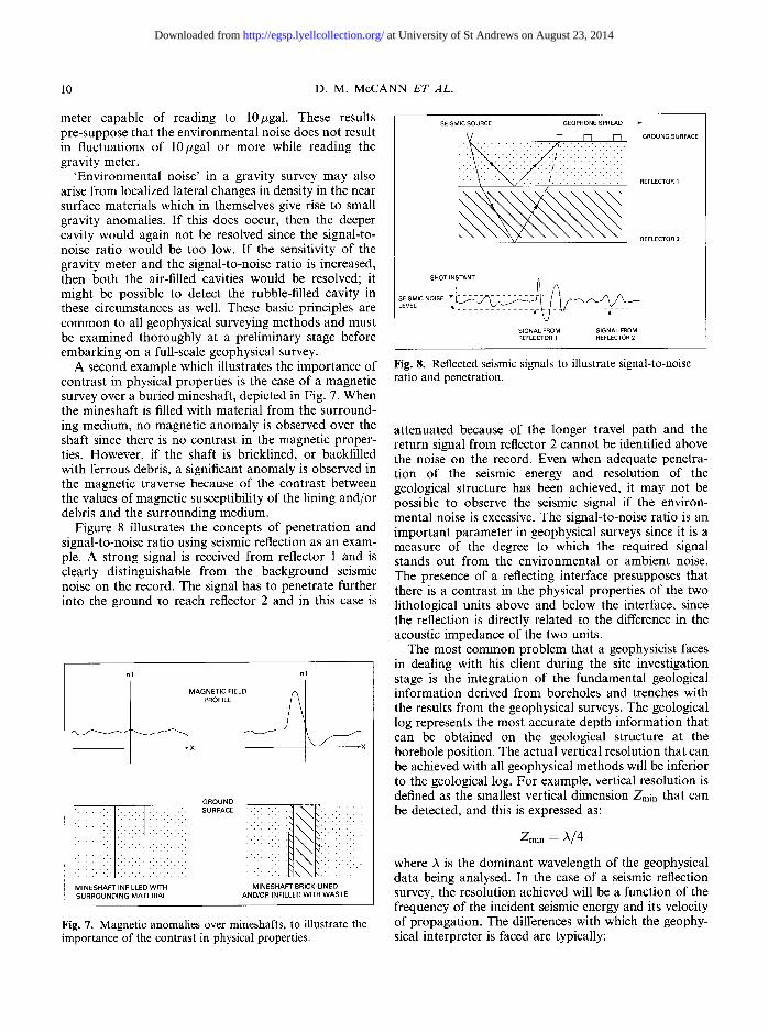
A second example which illustrates the importance of contrast in physical properties is the case of a magnetic survey over a buried mineshaft, depicted in Fig. 7. When the mineshaft is filled with material from the surround- ing medium, no magnetic anomaly is observed over the shaft since there is no contrast in the magnetic proper- ties. However, if the shaft is bricklined, or backfilled with ferrous debris, a significant anomaly is observed in the magnetic traverse because of the contrast between the values of magnetic susceptibility of the lining and/or debris and the surrounding medium.
Figure 8 illustrates the concepts of penetration and signal-to-noise ratio using seismic reflection as an exam- ple. A strong signal is received from reflector 1 and is clearly distinguishable from the background seismic noise on the record. The signal has to penetrate further into the ground to reach reflector 2 and in this case is
nT nT
' :""li 1 MINESHAFT INFILLED WITH SURROUNDING MATERIAL
GROUND SURFACE
!!ii!! i:::
MINESHAFT BRICK-LINED AND/OR INFILLED WITH WASTE
Fig. 7. Magnetic anomalies over mineshafts, to illustrate the importance of the contrast in physical properties.
SEISMIC SOURCE GEOPHONE SPREAD
i"::!! i : ~ : REFLECTOR 1
REFLECTOR 2
L E V E L � 9 . . . . ~ - ~ - kr - - ~ - - -
SIGNAL FROM SIGNAL FROM REFLECTOR 1 REFLECTOR 2
Fig. 8. Reflected seismic signals to illustrate signal-to-noise ratio and penetration.
attenuated because of the longer travel path and the return signal from reflector 2 cannot be identified above the noise on the record. Even when adequate penetra- tion of the seismic energy and resolution of the geological structure has been achieved, it may not be possible to observe the seismic signal if the environ- mental noise is excessive. The signal-to-noise ratio is an important parameter in geophysical surveys since it is a measure of the degree to which the required signal stands out from the environmental or ambient noise. The presence of a reflecting interface presupposes that there is a contrast in the physical properties of the two lithological units above and below the interface, since the reflection is directly related to the difference in the acoustic impedance of the two units.
The most common problem that a geophysicist faces in dealing with his client during the site investigation stage is the integration of the fundamental geological information derived from boreholes and trenches with the results from the geophysical surveys. The geological log represents the most accurate depth information that can be obtained on the geological structure at the borehole position. The actual vertical resolution that can be achieved with all geophysical methods will be inferior to the geological log. For example, vertical resolution is defined as the smallest vertical dimension ZInin that can be detected, and this is expressed as:
/min = A/4
where A is the dominant wavelength of the geophysical data being analysed. In the case of a seismic reflection survey, the resolution achieved will be a function of the frequency of the incident seismic energy and its velocity of propagation. The differences with which the geophy- sical interpreter is faced are typically:
at University of St Andrews on August 23, 2014http://egsp.lyellcollection.org/Downloaded from
GEOPHYSICAL SURVEYS 11
Sonic log data Seismic data
Vp = 4000 m/s V = 4000 m/s f = 10 kHz f = 25 Hz A =0.4m A = 160 m
Z m i n ~--- 0.1 m Zmin = 40 m
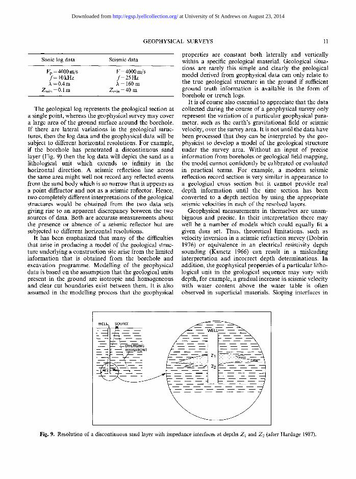
The geological log represents the geological section at a single point, whereas the geophysical survey may cover a large area of the ground surface around the borehole. If there are lateral variations in the geological struc- tures, then the log data and the geophysical data will be subject to different horizontal resolutions. For example, if the borehole has penetrated a discontinuous sand layer (Fig. 9) then the log data will depict the sand as a lithological unit which extends to infinity in the horizontal direction. A seismic reflection line across the same area might well not record any reflected events from the sand body which is so narrow that it appears as a point diffractor and not as a seismic reflector. Hence, two completely different interpretations of the geological structures would be obtained from the two data sets giving rise to an apparent discrepancy between the two sources of data. Both are accurate measurements about the presence or absence of a seismic reflector but are subjected to different horizontal resolutions.
It has been emphasized that many of the difficulties that arise in producing a model of the geological struc- ture underlying a construction site arise from the limited information that is obtained from the borehole and excavation programme. Modelling of the geophysical data is based on the assumption that the geological units present in the ground are isotropic and homogeneous and clear cut boundaries exist between them. It is also assumed in the modelling process that the geophysical
properties are constant both laterally and vertically within a specific geological material. Geological situa- tions are rarely this simple and clearly the geological model derived from geophysical data can only relate to the true geological structure in the ground if sufficient ground truth information is available in the form of borehole or trench logs.
It is of course also essential to appreciate that the data collected during the course of a geophysical survey only represent the variation of a particular geophysical para- meter, such as the earth's gravitational field or seismic velocity, over the survey area. It is not until the data have been processed that they can be interpreted by the geo- physicist to develop a model of the geological structure under the survey area. Without an input of precise information from boreholes or geological field mapping, the model cannot confidently be calibrated or evaluated in practical terms. For example, a modern seismic reflection record section is very similar in appearance to a geological cross section but it cannot provide real depth information until the time section has been converted to a depth section by using the appropriate seismic velocities in each of the resolved layers.
Geophysical measurements in themselves are unam- biguous and precise. In their interpretation there may well be a number of models which could equally fit a given data set. Thus, theoretical limitations, such as velocity inversion in a seismic refraction survey (Dobrin 1976) or equivalence in an electrical resistivity depth sounding (Kunetz 1966) can result in a misleading interpretation and incorrect depth determinations. In addition, the geophysical properties of a particular litho- logical unit in the geological sequence may vary with depth, for example, a gradual increase in seismic velocity with water content above the water table is often observed in superficial materials. Sloping interfaces in
_ I~~M. ~ WEL SOURCE ~ ~ __ ~ - ~ - ~ _ _ _ _ _ _
"~-61 v E-'~'l N G
Fig. 9. Resolution of a discontinuous sand layer with impedance interfaces at depths Z 1 and Z= (after Hardage 1987).
at University of St Andrews on August 23, 2014http://egsp.lyellcollection.org/Downloaded from
12 D . M . McCANN ET AL.
the geological sequence do n o t appea r in their correct pos i t ion in a seismic reflection or g r o u n d pene t ra t ing r ada r record a n d have to be mig ra t ed before they represent the t rue geological s i tuat ion.
A typical example o f h o w essential the geological i n f o r m a t i o n is to the in te rp re ta t ion o f a geophysical survey is in the c o m m o n appl ica t ion o f seismic refract ion techniques to the m a p p i n g o f bedrock . Whereas a ref rac tor o f seismic veloci ty in the range 4000 to 5000 m/s m a y be conf ident ly identif ied as ' bed rock ' or ' engineer ing rockhead ' , the ident i f icat ion o f mater ia l type o f velocities o f 1800 to 2500 m/s is of ten ambiguous ;
it cou ld represent ei ther a wea the red rock or a stiff clay, for example , mater ia ls which will have quite different engineer ing proper t ies . This s i tua t ion is, in fact, one o f the m o r e f requen t sources o f d iscrepancy between bed- rock depths de t e rmined in boreholes and f rom seismic re f rac t ion surveys.
Geophysical methods and their application
Geophys ica l m e t h o d s are conce rned with s tudy of the physical proper t ies o f the ear th a nd their use in the
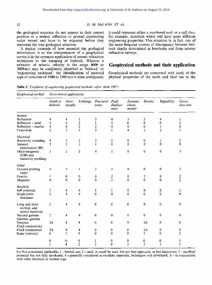
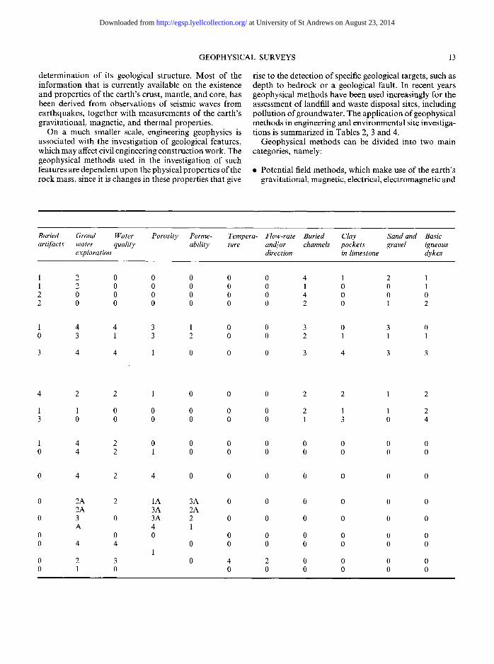
Table 2. Usefulness of engineering geophysical methods (after Anon 1997)
Geophysical method Geotechnical applications
Depth to Strat- Lithology Fractured Fault Dynamic Density Rippability bedrock igraphy zones displace- elastic
ment moduli
Cavity detection
Seismic Refraction 4 4 3 3 4 3 2 4 1 Reflection - land 2 2 2 1 2 0 0 0 2 Reflection - marine 4 4 2 2 4 0 0 1 0 Cross-hole 2 2 3 3 1 4 2 2 3
Electrical Resistivity sounding 4 3 3 2 2 0 0 1 2 Induced 2 2 3 1 0 0 0 0 0
polarization (IP) Electromagnetic 3 2 2 4 1 0 0 0 3
(EM) and resistivity profiling
Other Ground probing 2 3 1 2 3 0 0 0 3
radar Gravity 1 0 0 0 2 0 2 0 2 Magnetic 0 0 0 0 2 0 0 0 2
Borehole Self potential 2 4 4 1 1 0 0 0 1 Single point 2 4 4 0 0 0 0 0 0
resistance
Long and short 2 4 4 0 0 0 0 0 0 normal, and lateral resistivity
Natural gamma 2 4 4 0 0 0 0 0 0 Gamma-gamma Neutron 3A 4 4 0 0 0 3A 0 0 Fluid conductivity Fluid temperature 2A 4 4 0 0 0 3A 0 0 Sonic (velocity) 0 1 0 0 0 0 1 0 2
0 0 0 1 0 0 0 0 1 3 4 2 3 0 3 2 1 2
0 = Not considered applicable; 1 = limited use; 2 = used, or could be used, but not best approach, or has limitations; 3 = excellent potential but not fully developed; 4 = generally considered as excellent approach, techniques well developed; A = in conjunction with other electrical or nuclear logs.
at University of St Andrews on August 23, 2014http://egsp.lyellcollection.org/Downloaded from
GEOPHYSICAL SURVEYS 13
determination of its geological structure. Most of the information that is currently available on the existence and properties of the earth's crust, mantle, and core, has been derived from observations of seismic waves from earthquakes, together with measurements of the earth's gravitational, magnetic, and thermal properties.
On a much smaller scale, engineering geophysics is associated with the investigation of geological features, which may affect civil engineering construction work. The geophysical methods used in the investigation of such features are dependent upon the physical properties of the rock mass, since it is changes in these properties that give
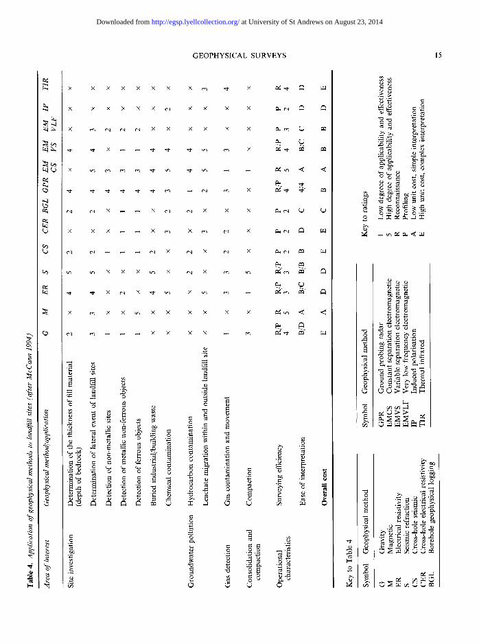
rise to the detection of specific geological targets, such as depth to bedrock or a geological fault. In recent years geophysical methods have been used increasingly for the assessment of landfill and waste disposal sites, including pollution of groundwater. The application of geophysical methods in engineering and environmental site investiga- tions is summarized in Tables 2, 3 and 4.
Geophysical methods can be divided into two main categories, namely:
�9 Potential field methods, which make use of the earth's gravitational, magnetic, electrical, electromagnetic and
Buried Grond Water Porosity Perme- artifacts water quality ability
exploration
Tempera- Flow-rate Buried Clay Sand and Basic ture and/or channels pockets gravel igneous
direction in limestone dykes
1 2 0 0 0 1 2 0 0 0 2 0 0 0 0 2 0 0 0 0
1 4 4 3 1 0 3 1 3 2
3 4 4 1 0
0 0 4 1 2 1 0 0 1 0 0 1 0 0 4 0 0 0 0 0 2 0 1 2
0 0 3 0 3 0 0 0 2 1 1 1
0 0 3 4 3 3
4 2 2 1 0
1 1 0 0 0 3 0 0 0 0
1 4 2 0 0 0 4 2 1 0
0 4 2 4 0
0 2A 2 1A 3A 2A 3A 2A
0 3 0 3A 2 A 4 1
0 0 0 0 4 4 0
1 0 2 3 0 0 1 0
0 0 2 2 1 2
0 0 2 1 1 2 0 0 1 3 0 4
0 0 0 0 0 0 0 0 0 0 0 0
0 0 0 0 0 0
0 0 0 0 0 0
0 0 0 0 0 0
0 0 0 0 0 0 0 0 0 0 0 0
4 2 0 0 0 0 0 0 0 0 0 0
at University of St Andrews on August 23, 2014http://egsp.lyellcollection.org/Downloaded from
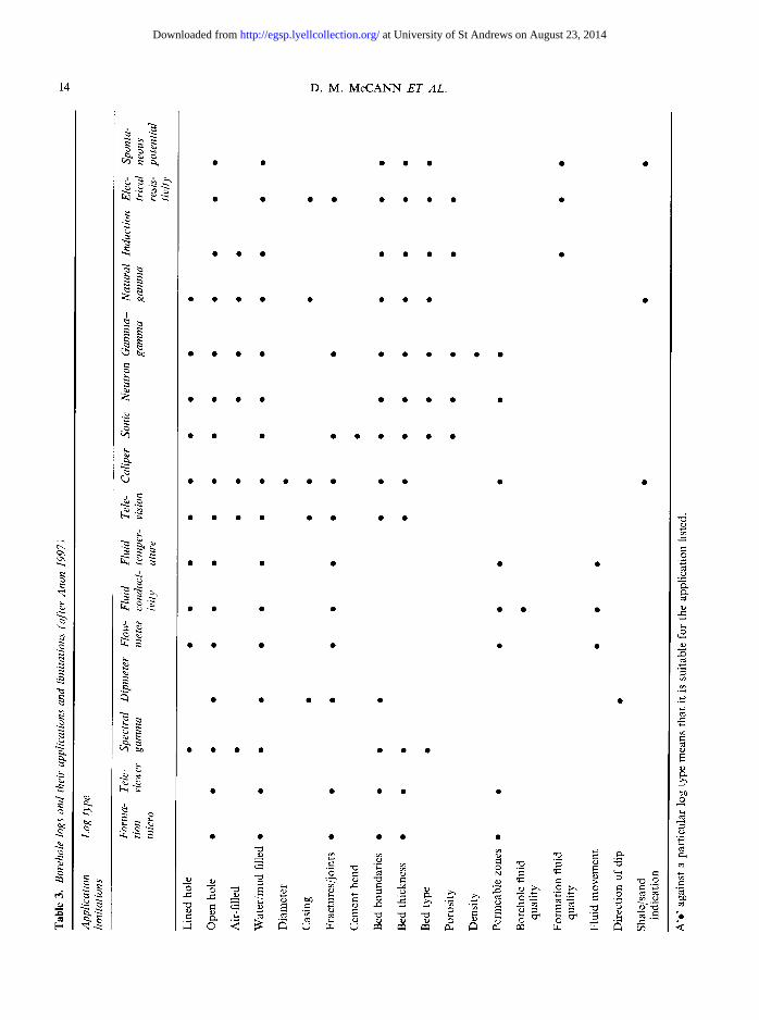
14 D . M . McCANN E T AL.
~t
q~
t,,..
,.4
[..
~s ~.~. ~.~
4.~
~-~
~ . ~
~ . ~
�9 �9 �9 �9 �9 �9 �9 �9
-~ ~ - ~ ~ i ~ ~.~
,= = ~ o ,-u.w fl
�9
at University of St Andrews on August 23, 2014http://egsp.lyellcollection.org/Downloaded from
GEOPHYSICAL SURVEYS 15
~b
da i i i l
[.i.
x x x x x x x x ~ ,~- x ~ m ' - !~
x x x x x x ~ x x x x ~ ~
X em e,I cN e,I X X X X X X I~.~ em (i) I~1
X X X ~ ~ X r,q X r ~ X I~., mq ~ [..z..]
r r ,,~ ,--, ,,-- cq X r X ~ X I ~ ~r',l 1~t r ~
x ~ x x ~ x x x x x x ~ < <
~ ~ o =
�9 ~ .~ ~ ~ ~ ~ o ~ ~ ~ ..=
0
0 ~ ~
2
~ ~o ~
&
0 0
~ b 1 3
0 0
~0 ~ .~ ~
�9 ~ o = .~ .~ .~
~ 8 ~r.T-1
at University of St Andrews on August 23, 2014http://egsp.lyellcollection.org/Downloaded from
16 D .M. McCANN E T AL.
thermal fields. Anomalous zones within the field are detected and measured in order to model the geological features which produce them.
�9 Artificial source methods where signals are sent into the ground from a seismic, electrical, or electromag- netic source and measurements are made at a series of detecting stations.
An excellent review of geophysical methods and their applicability to underground excavation is given by Mossman & Heim (1972). Of the main geophysical methods in use, gravity and magnetic measurements give very little indication of the structural characteristics of the rock mass, but find a limited application in cavity and mineshaft location. Seismic, electrical resistivity, and electromagnetic methods can provide considerable information on the rock mass both in regional context and the more localized area of a borehole.
Holes drilled on the engineering site provide access to the environment of interest and geophysical logging methods can be used to give information on the actual in situ conditions which prevail in each borehole. Most geophysical well-logging methods respond in some way to the presence of a discontinuity in the rock-mass. The response of the tool is governed by its resolution, the width and angle of the fracture of joint and the infilling material within the fracture. The effects of a weathered and fractured rock mass on various geophysical proper- ties are discussed in some detail by Sauu & Gartner (1979), Cratchley (1977) and McEwen et al. (1985); a general treatment of relevant interpretation procedures is given in Keys (1990). Provided the boreholes are close enough they can be used for cross-hole seismic, electromagnetic, and electrical resistivity surveys. Indi- vidual boreholes can also be used for surface-to-bore- hole measurements, which can also provide valuable information for the engineering characterization of the rock mass.
The information available on a rock mass can be increased by the use of geophysical techniques, which can provide an indirect assessment of its engineering properties. Of particular importance is the measurement of the seismic properties of the rock mass since the dynamic elastic moduli may be derived from the com- pressional and shear wave velocities. While the indirect determination of engineering properties is of particular value, it is the direct assessment of the rock mass condi- tion, such as the degree of fracturing, where the seismic parameters make their greatest contribution. In this case the seismic and engineering parameters can be viewed as complementary and of equal importance to the overall assessment of rock mass performance.
Seismic methods
Seismic surveys provide two types of information on the rock or soil mass:
�9 Seismic refraction and reflection surveys may be carried out to investigate the continuity of geological strata over the site and the location of major discontinuities, such as fault zones.
�9 From measurements of the compressional and shear wave velocities it is possible to determine the dynamic elastic moduli of the rock mass and estimate its degree of fracturing.
Seismic methods are based on the generation of seismic waves on the ground surface and the measurement of the time taken by the waves to travel from the source through the ground to a series of geophones laid out in a straight line from the source. The seismic energy can be generated by a number of sources including a sledge hammer and plate, falling weight, air gun, detonator, and explosives, and the resultant ground motion at the surface is detected by geophones.
Apart from seismic energy travelling directly through the rock mass to the geophone array two other main paths are possible:
�9 The refracted, or head, wave, which travels along the interface between the two rock types.
�9 The reflected wave from the interface between the two rock types.
Both the seismic refraction and reflection methods were considered in some detail by Telford et al. (1990), Dobrin (1976) and Parasnis (1986).
The seismic refraction method is widely used in site investigation. A typical example of its use in the study of the continuity of geological structure was given by Grainger et al. (1973), who described a seismic refrac- tion survey carried out in the Middle Chalk at Mundford, Norfolk, UK. They showed that the com- pressional wave velocity increased in well defined steps, that broadly correlated with the rock mass classification system adopted by Ward et al. (1968). In this system, the Chalk was classified, by observations in boreholes, into five engineering grades. The correlation was established in an area of lithologically uniform chalk on seismic lines that had good borehole control, both to classify the rock mass in engineering terms from the seismic classification, and to study the continuity of the seis- mic section. Grainger et al. (1973) emphasized that the seismic classification was only applicable in the specific lithological section for which it was derived and should not be extrapolated outside the immediate calibrated area.
Cratchley et al. (1976) carried out a detailed seismic refraction survey along the line of a tunnel constructed as part of the Foyers pumped storage hydro-electric scheme near Inverness, Scotland. Their results clearly identified a highly weathered fault zone, which inter- sected the tunnel line on the Loch Mhor heading. Measurements in the tunnel itself confirmed the presence of a low velocity zone where the rock was generally
at University of St Andrews on August 23, 2014http://egsp.lyellcollection.org/Downloaded from
GEOPHYSICAL SURVEYS 17
shattered and faulted, which led to the use of steel ribbing during the tunnel construction.
Mossman & Hein (1972) used seismic methods to provide information on the geological conditions in the Chicago area prior to the excavation of a series of tunnels. The prime concern of the survey was the recog- nition of any faulting resulting in the vertical displace- ment of the rocks at depth and the identification of heavily fractured, water-bearing zones associated with the faulting. Depth to bedrock, which is usually less than 50 m was determined from a seismic refraction survey, in which closely spaced survey lines were used to map the irregular erosional surface. However, tunnels also were planned in a deeper dolostone layer at a depth of approximately 180m. In this case seismic refraction surveys would not give the desired information because of the long length of survey lines required and the large offsets between the seismic source and the geophone array. Hence a seismic reflection survey was carried out using the Vibroseis method and the top surface of the dolostone layer was mapped over the area of interest to a precision better than 6m. The seismic survey also identified thirty faults, some with vertical displacements as low as 4 m. Most were unknown at the surface. The results of the seismic survey were mostly confirmed by the subsequent drilling and excavation programme and clearly demonstrated the cost benefits to be derived from a properly organized seismic programme.
In dam site areas, in particular, grouting often is carried to increase the bearing capacity or reduce the permeability of the foundation rock in the reservoir area, where it is highly fractured. Geophysical surveys may be carried out to locate these zones of fractured rock and these can be treated with a selective grout- ing programme. Knill (1970) carried out seismic surveys in the rock mass adjacent to 69 concrete dams in the UK to determine the in situ compressional wave velocity. A relationship was established between the curtain grout take and velocity using the Fracture Index as follows:
FI = VFIELD / gLAD (1)
where VFIEL D is the compressional wave velocity in situ and VLAB is the compressional wave velocity measured on an intact saturated rock specimen in the laboratory.
Knill (1970) showed that seismic measurements can be used to predict the grout take and to assess the depth of foundation deformability and the excavation method used.
Scalabrini et al. (1964) also used a sonic method to determine the in situ state of the foundation rock at the Frera Dam both before and after grouting of the rock mass took place. The dynamic elastic modulus was meas- ured in the abutment rock at twenty nine points and the information was used to develop and carry out a com- prehensive grouting programme. Following the comple- tion of this programme, the dynamic elastic modulus was determined again at 20 points in the grouted rock
mass and it was shown that the measured values were very close to those determined in deep sound rock.
Deere et al. (1967) proposed the use of the rock quality designation (RQD) index and the seismic velocity index as an estimate of rock mass deformability. The seismic velocity index is defined as:
s g I 2 2 = VFIELD/VLAB (2)
where VFIEL D and VLAB are defined by Equation (1). Coon & Merritt (1970) demonstrated that neither
index, on its own, is sufficient to describe fully the overall condition of the rock mass and showed that when the ratio was used for the prediction of the in situ modulus of deformability its resultant value was as much as three times greater than the corresponding laboratory value on an intact rock.
Engineering geophysicists have made many attempts to relate, empirically, the geophysical properties of the rock mass to its mechanical properties but this can only be achieved in general terms. McCann et al. (1990) suggested that no attempt should be made to obtain precise values of uniaxial compressive strength from compressional wave velocity determinations since the relationship between these two parameters is essentially non-linear. Rock types can be classified qualitatively in simple terms on the basis of velocity measurements (for example, weak to very weak or strong to very strong). The same observation applies to the correlation of a function of velocity with RQD. However, many of the parameters used in current rock classification systems (for example, RQD, strength, fracture condition etc.) do affect the magnitude of the seismic velocity determined in the field and, hence, seismic velocity can be used to classify the rock mass in terms of the geomechanical classification system, particularly where individual lithological types are being evaluated.
There has been very little published on the use of seismic methods for the investigation of landfill sites. Use of the method is mainly restricted to the investiga- tion of the internal structure of the fill material and its thickness above the underlying bedrock. The method is usually too slow and hence too expensive for the eco- nomic surveying of a large landfill site. Carpenter et al. (1991), Knight et al. (1978) and Nunn (1974) described seismic refraction surveys on landfill sites in Chicago, USA, Sydney, Australia and Brownhills, UK, respec- tively. An interesting feature of all three studies is that although the fill material was variable in composition, the range over which the values of compressional wave velocity varied was comparatively small and this factor simplified the calculation of the depth to bedrock.
Electrical resistivity
Electrical depth soundings are effective in horizontal stratified media, since the spatial distribution of the
at University of St Andrews on August 23, 2014http://egsp.lyellcollection.org/Downloaded from
18 D .M. McCANN ET AL.
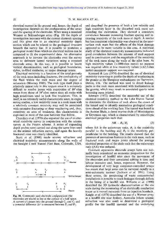
electrical current in the ground and, hence, the depth of investigation depends on the configuration of the array and the spacing of the electrodes. When using a standard Wenner or Schlumberger array (Fig. 10) the depth of investigation increases with the current electrode spacing and this gives rise to an electrical resistivity depth section which can be related to the geological structure beneath the survey line. It is possible to postulate a geological model from which an electrical section can be computed to fit the experimental data. An alternative approach is to traverse the electrodes over the survey area to delineate lateral variations using a constant electrode array. In this way, it is possible to locate vertical discontinuities, such as geological boundaries, dykes, in-filled sinkholes, or major drainage zones.
Electrical resistivity is a function of the total porosity of the rock mass including fractures, the conductivity of the fluid within the rock mass and the degree of saturation (Mooney 1980). The rock type itself plays a relatively minor role in this respect since it is extremely difficult to resolve layers with resistivities of 103 ohm metre from those of 104 ohm metre since all rocks with high resistivities tend to look like insulators. This, in itself, is an extremely useful characteristic since, in engin- eering studies, a low resistivity zone in a rock mass with a relatively constant resistivity may well be associated with extensive fracturing or deep weathering and, thus, constitute an area of weakness; this characteristic is exploited in most of the case histories that follow.
Cratchley et al. (1976) also reported the use of an elec- trical resistivity survey in conjunction with the seismic survey at the Foyers scheme. A series of expanding depth probes were carried out along the same lines used on the seismic refraction survey, and again the heavily fractured zone was clearly identified.
Scott et al. (1968) made seismic refraction and electrical resistivity measurements along the walls of the Straight Creek Tunnel Pilot Base, Colorado, USA,
, AV ,,-
C1 P1 P2 C2
- I ~' ~ ~' ~' +1 I" a "1- a =',~ a "1 Wenner
C~ P1 P2 C2
~ I ~1~1 -t }= L ~,l'q L =! Schlurnberger
Cl C2 P1 P2
F a t Dipole
Fig. 10. C o m m o n l y used electrode conf igurat ions (the electrodes are placed in l ine at the surface o f a ha l f space. A current (I) passes into the ground through C1 and C2 and a potential difference AV is measured between P1 and P2.
and described the presence of both a low velocity and high resistivity layer in the disturbed rock mass sur- rounding the excavation. They showed a consistent correlation between increasing fracture spacing and in- creasing resistivity of the rock mass at depth. A similar but less consistent relationship was observed in the near- surface rock mass but the effects of the blast damage appeared to be more variable in this area. A statistical study of the electrical resistivity measurements indicated good correlation between the amount of steel support used in construction and the magnitude of the resistivity of the rock mass along the walls of the pilot bore. At high resistivity values (>1000ohm metre) no support was required while at low resistivity values (<62.5 ohm metre) maximum support was required.
Kennard & Lea (1974) described the use of electrical resistivity traversing to profile the depth of weathering in the granite at the Sheepstor embankment on Dartmoor, Devon, UK. The method was used to detect leakage paths in the rock mass associated with kaolinization in the granite, which may result in associated quartz veins becoming open jointed.
Schwarz (1972) described the successful use of the electrical resistivity method in the Lake Huron Tunnel to determine the thickness of rock above the crown of the tunnel and to identify anomalous geological condi- tions ahead of the working face. The tunnel was bored in the Antrim Shale, a dense marine shale of Mississippian or Devonian age, which is characterized by anisotropic electrical properties such that:
AR = R 1 / R 2 (3)
where AR is the anisotropy ratio, R1 is the resistivity parallel to the bedding and Re is the resistivity per- pendicular to the bedding. The results showed that the presence of anomalous features in the rock mass, such as fractured rock and major joints altered the average electrical properties of the shale such that the anisotropy ratio (AR) was reduced.
Constant separation electrode arrays have not nor- mally been considered an economic proposition for the investigation of landfill sites since the movement of the electrodes and their associated cabling is time and labour intensive and, hence, expensive. However, the development of very large computer-controlled arrays has meant that large areas can be surveyed rapidly in a semi-automatic manner (Jackson et al. 1991). Using these arrays, the monitoring of waste contaminated installations is possible to track leakages through defects in the lining of a landfill site. Williams et al. (1990) described the 3D hydraulic characterization at the site scale during the monitoring of an electrically conductive tracer as it moved outwards from an injection borehole. Knight et al. (1978) described the use of a Wenner array at a landfill site near Sydney, Australia (where seismic refraction was also used) to determine a geological profile for the landfill material and the underlying
at University of St Andrews on August 23, 2014http://egsp.lyellcollection.org/Downloaded from
GEOPHYSICAL SURVEYS 19
formation. The array was used to obtain two profiles at right angles to each other at each location. Although there were lateral changes in the electrical properties of the fill material because of its heterogeneous nature, the difference between the two profiles at each point was quite small and Knight et al. (1978) concluded that the site could be represented by a layered electrical structure with no systematic lateral electrical variations.
Many case histories describe the use of the electrical resistivity method in the study of leachates from landfill sites. Cartright & McComas (1968) investigated a number of landfill sites in Illinois, USA to test the possibility of detecting and tracing any chemical alteration of ground- water leachates from buried refuse. They concluded that while variation in apparent resistivity values reflected appreciable changes in water quality, some of the varia- tion could be attributed to lithological changes. Finch (1979) used the resistivity method to delineate contami- nated groundwater in the Bunter (now Sherwood) Sand- stone aquifer in Nottinghamshire, UK. It was clearly demonstrated that in an area where there is little litho- logical variation, the level of concentration of chloride ions in the pore water can be related to the resistivity sounding data.
Magnetic methods
In a magnetic survey variations in the Earth's magnetic field are measured. The method has the advantage of being one of the easiest and cheapest geophysical tech- niques to carry out, since large areas can be covered quickly at a low cost and few corrections to the field data are required. The main requirement for achieving an accurate magnetic map of the area of interest is that the diurnal variation in the Earth's magnetic field should be monitored, usually by a recording magnetometer at a base station, so that the actual magnetic readings obtained during the survey can be reduced to a common datum. To be of any value there must be variation in the magnetic properties of the rocks present in the survey area. However, possible magnetic anomalies on an engineering site can originate from man-made targets such as brick-lined shafts or the remains of ancient dwellings. In the UK, magnetic surveying has been widely used for the detection of abandoned mine shafts and adits, which cause considerable problems in areas where mining activity has ceased and poor, or no, records are available of the positions of the mines and their associated shafts. Examples of the use of mag- netic surveys for the above application were given by Dearman et al. (1977), Gallagher et al. (1978) and McCann et al. (1987). In geological surveying, magnetic dykes within the rock mass can be located and traced in areas where there is a superficial cover which masks their presence; a simple example of this application was given by Culshaw et al. (1987).
Magnetic methods can be used to detect buried ferrous objects or other magnetic materials within fill material. Fenning & Veness (1992) described the location of underground storage tanks and Leech & Johnson (1992) and Benson & Glaccum (1980) located buried steel drums. The lateral extent of landfill material can be determined where the magnetic properties of the fill differ from those of the surrounding rock mass.
Gravity
Gravity surveying involves the measurement of the Earth's gravitational field, which is a function of:
�9 Distance from the centre of the Earth. �9 Centrifugal acceleration due to the Earth's rotation. �9 The distribution of the mass, which is controlled by
the presence of hills and valleys in the vicinity of the observation point and changes in the density of rocks in the Earth.
After making the necessary corrections to the recorded data, the final gravity anomaly map represents variation in the mass distribution in the Earth. For many years little use was made of the method in site investigation and the method found its greatest application in the study of deep structures.
However, with the availability of more sensitive gravity meters, which are capable of measuring changes in the gravity field of the order of 5 #gal, the method has been used increasingly in the location of cavities, voids, and abandoned mineshafts (Neumann, 1977; Greenfield, 1979). Variations in density of the near-surface materials also can give rise to a gravity anomaly and the thickening of the superficial deposits relating to the presence of a buried valley was studied by Cornwall & Carruthers (1986). The delineation of waste material in landfill schemes is also another practical example of the use of the gravity method (Neumann 1977).
Electromagnetic methods
The use of electromagnetic methods in geotechnical investigations has increased over the past decade or so. In most cases electromagnetic energy is introduced into the ground by inductive coupling and is produced by passing an alternating current through a coil or loop; the receiver also detects its signal by induction. Most electromagnetic methods involve the use of a portable power source, although use has been made of both powerful long range transmitting stations and atmo- spheric energy arising from world-wide thunderstorm activity. Pulse electromagnetic energy also has been used for the detection of geological discontinuities, such as fault zones and open and infilled cavities.
The terrain conductivity meter is commonly used in engineering studies. Over a uniform half-space the
at University of St Andrews on August 23, 2014http://egsp.lyellcollection.org/Downloaded from
20 D.M. McCANN E T AL.
technique is analogous to carrying out a conventional resistivity survey with a fixed electrode spacing and the meter reads a direct conductivity value which is the inverse of the apparent resistivity value determined from the fixed array. Penetration between 4 and 6 m can be achieved and McDowell (1981) described the use of the meter for the rapid location of near-surface anomalous ground conditions. Culshaw et al. (1987), in their review of the use of geophysical methods in geological map- ping, described a survey carried out at Bridgend where the presence of fissures in the limestone was detected by a conductivity survey.
Glaccum et al. (1982) monitored a leachate plume using successive ground conductivity surveys. The ground conductivity meter, which primarily responds to changes in the electrical conductivity of the groundwater, is com- monly used for the detection of zones of contaminated water within a landfill site and its movement into the surrounding rock mass. Relative leachate concentrations surrounding a landfill site with leaking lagoons were investigated by Slaine & Greenhouse (1982), while Ladwig (1983) examined the acidity of groundwater draining from a mine. More recently, the transient electromagnetic method has been used increasingly on landfill sites (for example, Hoekstra et al. (1992) and Buselli et al. (1990)). Glaccum et al. (1983) measured the movement of leachate plumes across a contaminated area by carrying out successive EM surveys.
In the VLF method the electromagnetic waves trans- mitted by long range radio stations may be used to determine the electrical properties of the Earth. The depth to which radio waves can penetrate into the Earth is quite limited and low frequency transmissions are desirable. Measurements of resistivity based on electro- magnetic energy are, thus, mainly applicable to the soil cover and overburden (man-made and natural superficial deposits). In site investigation the method has found particular application in the delineation of water-filled faults and fault zones in the rock mass (Paterson & Ronka 1971; Phillips & Richards 1975).
Electromagnetic pulse techniques also have been used more frequently. They have been used both in the reflec- tion mode (Dolphin et al. 1974) and in the direct trans- mission mode (Lytle et al. 1979; Laine 1980). As was mentioned above, attenuation of the electromagnetic energy is the biggest problem encountered but, never- theless, the method has found considerable application in the investigation of sites located in very dry areas. Considerable penetration of electromagnetic energy is also reported in low porosity rocks, such as limestone, and Laine (1980) described the location of a cavity in limestone by the direct transmission method at a frequency of 10 MHz. The method used is very similar to the cross-hole seismic technique. Similar experiments were carried out by Lytle et al. (1979), who used electro- magnetic energy in the frequency range 10 to 70 MHz., and described a number of interesting case histories.
An interesting case history using a reflected electro- magnetic pulse was described by Dolphin et al. (1974). In this application the technique was applied at an archaeological site and electromagnetic energy in the frequency range 16 to 50 MHz was used. The application of the electromagnetic pulse reflection system to the detection and identification of geological and man-made anomalies which represent hazards ahead of the working face in hard rock rapid tunnelling operations was des- cribed by Moffat & Peters (1972); their experiments with various targets buried in the overburden, and also the limestone rock mass, demonstrated the feasibility of this approach. Further developments of the method were described by Moffat & Puskar (1976), in which the use of the electromagnetic pulse system is discussed in relation to a number of practical field situations.
Ground penetrating radar techniques also have been examined by Cook (1972, 1975, 1977). Using only low- power experimental radar equipment, reflection sig- nals were obtained through 13 m of limestone, through 9 to 18 m of coal and through 225 m of rock salt. By the late 1970s a commercial ground probing radar system had been developed and its use in a wide range of field application was discussed by Darracott & Lake (1981). For normal use the transmitting and receiving antenna are mounted within a mobile trolley but for specialised cross-hole or surface to borehole measurements the two antenna are operated separately. The electromagnetic energy is propagated in pulse form at frequencies in the range 50 MHz to 1 Ghz. The depth of penetration of electromagnetic energy can vary from hundreds of metres in rock salt to less than one metre in clay material. A general rule is that for a given material the lower the frequency of transmission, the greater the depth of penetration, while the higher transmission frequencies increase the resolution but reduce the depth of penetration.
Many uses of ground penetrating radar have been described in the literature including the determination of permafrost thickness (Annan & Davis 1976), the detec- tion of fractures in rock salt (Unterberger 1978) and the assessment of fracturing in a granite rock mass (Olsson et al. 1983). Other civil engineering applications are described by Rubin & Fowler (1978), Benson & Glaccum (1979), Leggo (1982), Leggo & Leech (1983) and McCann et al. (1988). The use of ground probing radar to locate drums, tanks, utility lines, trenches, as well as hydrocarbons floating on the water table has been described by Bowders et al. (1982), Fenner et al. (1992) and Fenning & Venness (1992).
Borehole geophysical methods
The construction of underground structures requires considerable information on the engineering and hydro- geological properties of the rock mass. Site investigation
at University of St Andrews on August 23, 2014http://egsp.lyellcollection.org/Downloaded from
GEOPHYSICAL SURVEYS 21
boreholes provide core samples that can be tested in the laboratory using standard rock and soil testing methods. However, core recovery may be less than 100%, samples taken from boreholes may be highly disturbed, and even the most carefully taken sample is subject to stress relief as it is removed from the ground. Laboratory tests on intact core samples from boreholes give an approximate representation of the actual in situ engineering properties of the rock mass; little or no account can be taken of discontinuities present on anything but a small scale. Hence, there has been considerable effort applied to the development of in situ testing methods for use in bore- holes to optimize the useful information that can be obtained from a borehole study.
To the geophysicist, a borehole is an access path to the ground that can be investigated by the use of geophysical methods. The geophysical properties of the ground are directly determined and can be related to its lithological and geotechnical properties. Con- siderable research has been carried out in this field and this has been aimed directly at the concept of determining engineering properties from indirect geo- physical measurements made in, or between, bore- holes. The geophysical properties are controlled by the geotechnical properties of the ground but the relation- ships are essentially multi-dimensional so that the rock or soil fabric and the interstitial fluids both play a part in controlling the overall engineering character- istics. Fracturing either on a micro-scale in the rock matrix or on a macro-scale in the rock mass has an additional effect on the engineering performance of the rock mass.
The site investigation boreholes can be used in two ways for geophysical investigation:
�9 A wide range of geophysical borehole logging tools can be deployed in each borehole to provide con- tinuous measurements with depth of a range of geophysical parameters.
�9 Cross-hole seismic or electromagnetic measurements may be carried out between adjacent boreholes to provide an engineering assessment of the rock mass indirectly from the geophysical properties.
Geophysical well logging methods. The methods examine the geophysical properties of an annulus of rock around the borehole and, thus, act upon a much larger volume of rock in situ than that represented by a core sample. The influence of jointing, fracturing, weathering and even lateral lithological variation will all be reflected in the measured parameters. Geophysical logging provides additional data to those obtained from core logging, laboratory testing of cores, and in situ observations and measurements. The logging results can be used in conjunction with geotechnical and hydrogeological information to extend the basic rock mass classification system used.
Caliper log The caliper log is used to obtain an accurate profile of the diameter of the borehole down its length, since correction for any changes in this parameter have to be applied to most other geophysical logs run in the borehole The log can be used, to a certain extent, for the identification of lithology and stratigraphic correlation but its most important use arises in the location of zones of fractured rock. The observation of borehole 'break- outs' also can be noted in the caliper log and this can be used to determine the direction of the in situ stress field (Evans & Brereton 1990). The basic principles of caliper logging are described in some detail by Hilchie (1968).
Sonic log In its simplest form, the sonic log is a recording of the time, 6t, taken by a compressional (P) wave to travel a defined length of formation plotted against depth. In the oil industry, this is expressed as microseconds per foot, but in civil engineering applications the more familiar units of microseconds per metre are used. The basic sonic log is used mainly to compute the formation porosity via the time average equation of Wyllie (1956), as follows:
1 �9 (1 - ~ ) - + - - ( 4 )
Vr Vf Vs
where e9 is the effective porosity, Vr is the compressional wave velocity in the rock mass, Vs is the compressional wave velocity in the rock matrix and Vr is the com- pressional wave velocity in the fluid and 100% satura- tion of the rock mass is assumed.
The P wave velocity also is affected by the presence of fracture zones on horizontal and sub-horizontal frac- tures. Thus, the sonic log responds to the effective porosity of the rock mass. The presence of vertical fractures does not affect the P wave velocity to any great extent. Hence, the sonic log responds only to the porosity of the rock matrix, and too low a value of bulk porosity will be indicated.
With the full wave train sonic log it is often possible to measure the velocities of both the compressional (P) and shear (S) wave velocities (Geyer & Myung 1970). The actual log is usually presented in the form of a variable density plot. It is not always possible to identify the S wave since there is often no distinct break at the onset of the shear wave pulse or the shear wave is highly attenuated. In the latter case this is extremely useful in picking out zones of highly fractured rock.
Using values of the formation density computed from the gamma-gamma log, it is possible to calculate the dynamic elastic properties of the rock mass from the P and S wave velocities as follows:
Bulk Modulus (K)
I ( = p ( V ~ - 4 v ~ ) (5)
at University of St Andrews on August 23, 2014http://egsp.lyellcollection.org/Downloaded from
22 D .M. McCANN ET AL.
where p is the bulk density, Vp is the compressional wave velocity and Vs is the shear wave velocity
Shear Modulus (#)
# = p V 2 (6)
Poisson's Ratio (~5)
6 = ~ - 1
( V p / V s ) 2 - 1 (7)
Young's Modulus (E)
E = 2pV2(1 - 6). (8)
McCann & Entwisle (1992) showed that the dynamic values of Young's modulus derived from the full wave train sonic and formation density borehole logs are a reasonable estimate of the engineering properties of the rock mass provided that due regard is given to its lithology. The 1 : 1 relationship between the dynamic and static values observed in their study for harder, denser rocks confirms the conclusions of other authors such as King (1983) and Eissa & Kazi (1988). The study of McCann & Entwisle (1992) also showed that, for softer mudrocks and alluvial materials, the ratio between the dynamic and static values of Young's modulus can be as high as 200:1 where the materials are subject to plastic rather than elastic deformation. This ratio does vary between these two extreme values but, provided due attention is given to lithology it is possible to correlate the dynamic values obtained from the borehole logs with the static values obtained from laboratory testing.
The difference between the dynamic and static values of Young's modulus is controlled by the low strain levels (10 -5 ) at which the dynamic values are measured com- pared with the strain levels of 10 -3 to 10 -2 measured in the static test. The different strain levels have little effect on the stronger, well-cemented rocks since they may be considered to perform in a quasi-elastic manner and return to their original state after the loading is removed in the static test. The softer clays and mudrocks are subjected to plastic deformation on loading and, clearly, the strain level is a significant factor in the static case since these samples do not return to their original state.
The presence of fractures in the rock mass will interfere with the transmission of elastic wave energy along the wall of the borehole. In highly fractured rock both the velocity of propagation and amplitude of a compressional wave is considerably reduced and similar characteristics have been noted for shear waves.
Laboratory and field values of Vp and Vs, the velocities of the compressional and shear waves respec- tively can be used to compute a fracture index following the procedure suggested by Knill (1970) in equation (1).
To produce an index with a range from 0 to 1 equation (1) has been modified as follows:
Sonic Fracture Index (SFI) = V L - - V M
v L - W (9)
where VF < VM < VL, Vv is the compressional wave velocity in the borehole fluid, VM is the measured compressional wave velocity at any depth in the bore- hole and VL is the compressional wave velocity measured on intact rock samples in the laboratory.
Radioactive Logs Natural gamma. This log is a measurement of the natural radioactivity of a formation and is useful for lithological identification or stratigraphic correlation. The log also can be used for the identification of zones containing radioactive minerals such as potash or uranium-rich ores.
Gamma-gamma. This log measures the intensity of gamma radiation from a radioactive source in the sonde, such as cobalt 60 or caesium 127, after it is backscattered and attenuated within the borehole and the surrounding rock mass. Provided the necessary calibrations are applied to the sonde, the recorded count rate is directly proportional to the formation density. The effects of variation in the borehole diameter are offset by forcing the sonde against the wall of the borehole with an excentering arm.
The main use of the gamma-gamma log in the oil industry is the determination of formation porosity, while in engineering investigations it is the formation density that is most applicable. The sonde also can be used for lithological correlation and identification of forma- tions within a single geological area. Bulk density can be measured to an accuracy of +0.05 Mg/m 3 but this can be improved by careful calibration of the source detec- tors, and instrumentation and considerable care in the preparation of the borehole.
The gamma-gamma log measures the effective density of the formation close to the borehole wall and this includes the effects of both the rock matrix and the contained fluids. The log responds to both horizontal and vertical fractures and tends to indicate higher poro- sities than those derived from a sonic log over a com- parable section of borehole intersected by a high angle fracture or joint plane. A cross-plot of porosity derived from the two logs can be used to indicate the presence of significant fracture zones within the rock mass.
Neutron-neutron. The neutron-neutron sonde is used to measure formation porosity or moisture content since it responds primarily to the amount of hydrogen present in the formation. A plutonium-beryllium or an amer- icium-beryllium source is used to provide the neutrons. The best results are obtained with the neutron source
at University of St Andrews on August 23, 2014http://egsp.lyellcollection.org/Downloaded from
GEOPHYSICAL SURVEYS 23
and detector pressed against the borehole wall to minimize borehole effects. For accurate determination of moisture content or porosity very careful calibration of the sonde is required, particularly at low porosity values. The neutron sonde responds to the total water content of the formation and, since this would include adsorbed water associated with clay minerals, the porosity measured on a shale, for instance, will be greater than the effective porosity of the formation. The log is usually very subdued in low porosity crystalline rocks but the presence of a fracture zone will artificially increase the effective porosity and a significant reduction in the neutron count will be observed.
Electrical methods The underlying theory of electrical logging devices is considered in detail in Keys (1990) and only a brief summary is given here.
Spontaneous potential log. The spontaneous potential log is a recording versus depth of the natural potential development between the borehole fluid and the surrounding rock mass. The log is used mainly for the detection of permeable beds, the location of their boundaries and their correlation between adjacent boreholes. In a low porosity rock mass, such as granite, variations in spontaneous potential will be related to zones of fractured rock associated with joint patterns or fissures but the measured values cannot be applied in a quantitative manner to obtain formation permeability.
Single point resistance log. This is the simplest of the electrical logging systems, in which a lead electrode is lowered down the borehole on an insulated cable with an electrode buried at the surface to provide the return' path for the current flow. The measured resistance is a function of the formation resistivity so that variations are related directly to changes in lithology and the log has been used on a lithology tool for geological correlations between boreholes. Although the depth of investigation (into the borehole wall) is only between 50 and 100mm, the log will respond to fractures in the borehole wall and is often used in conjunction with the caliper log to investigate fracturing in the rock mass.
Normal devices. A more realistic value of the apparent resistivity is required to compute the in situ porosity of the rock mass and this is achieved by use of the normal logging tool which passes current deeper into the rock mass depending on the electrode separation.
The normal tools are most effective in low to medium resistivity media, the short normal log proving particu- larly useful for geological correlation between boreholes. In low porosity rocks, such as granite, the resistivity of the rock mass is very high and the major factor
influencing the resistivity log will be joint patterns. The effects of fractures and joints can be observed in a qualitative manner in the rock mass by a comparison of the short and long normal logs.
Focused devices. The resistivity sondes described above are all relatively insensitive in high resistivity formations since most of the current flow is in the borehole fluid and very little enters the formation. This results in poor resolution of the bed boundaries and the apparent resistivity measured is not representative of the formation resistivity.
This limitation has been overcome in a high resistiv- ity formation by the introduction of focussed resistivity tools. The underlying concept is that if the measuring current is forced to flow radially as a thin sheet of current into the formation being logged, then the influence of the borehole and the surrounding formation on the resistiv- ity measurement is minimized.
The resistivity tools described above are used for both shallow and deep investigations of the rock mass from the borehole. In highly resistive crystalline rocks the resistivity logs are normally insensitive to the small changes brought about by variations in lithology. However, where substantial fracturing is present, the rock mass becomes more permeable and the log response will be affected by the fracture orientation, the radial and vertical length of the fracture, and the fluid.
In a very low porosity rock mass the conductivity network formed by the fracture zone may be largely unidirectional resulting in a value of apparent resistiv- ity that is significantly different from that measured in an isotropically conductive medium; this effect is ob- served particularly with deep focused devices (Sauu & Gartner 1979).
Dipmeter. A dipmeter is usually a four-arm (but can be three or six-arm) side-wall micro-resistivity device, which measures fine variations of resistivity in the formation with such a resolution that the relative vertical shift of characteristic patterns of variation on the traces can be used to derive the attitude of a plane intersecting the borehole. Such patterns can be caused by bedding planes, changes in lithology, or fractures and joints in the rock mass. The patterns are arranged across the traces as sinusoids. Computer analysis can identify the patterns by cross-correlation, and perform the trigonometrical solution, incorporating the rela- tive shift of patterns, the orientation of the sonde and the borehole dimensions, to derive the attitude of the planes.
Formation scanning tool. The high-resolution dip- meter log is an effective indication of a high fracture density within a borehole. In a development of the sonde described by Lloyd et al. (1986), two of the four dipmeter pads carry electrical micro-scanners each
at University of St Andrews on August 23, 2014http://egsp.lyellcollection.org/Downloaded from
24 D.M. McCANN E T AL.
consisting of 27 buttons. The basic principle is to map the conductivity of the borehole wall with a dense array of sensors. These give a very high-resolution electrical image of the formation when they have been speed- corrected and are displayed on a variable intensity grey level scale. The data from the two arrays can be used to produce a very high-resolution (2.5mm by 2.5mm) image of two strips down the borehole wall. The data are produced in digitized form and can be processed by a computer-based interpretational package described by Lanyon (1986) for direct comparison with the records from the borehole televiewer.
Televiewer The televiewer pulses ultrasonic energy from a piezo- electric transducer to the borehole wall via the fluid in the borehole, where some of the energy is reflected and detected by the transducer (now acting as a receiver). The transducer is rotated in the borehole at 3 rev/s and is orientated relative to the earth's magnetic field by a downhole magnetometer within the sonde. The ampli- tude of the reflected signal is proportional to the reflected energy, which is a function of the acoustic impedance of the borehole wall. Presentation of the processed data on an electrostatic plotter gives a flattened picture of the borehole wall with fractures appearing as sine waves.
Television Borehole television logging involves the use of a low- light sensitive closed circuit television camera system, specially adapted for use under water. Illumination is from a variety of external peripheral lighting heads attached to the camera and selected to suit the individual borehole conditions.The camera can be packaged as small as 50 mm diameter and can operate in boreholes to a minimum diameter of 100mm allowing for adequate clearance. For general usage, a simple axial view of the borehole is adequate, but for details of features on the borehole wall, mirror assemblies give a radial view which can be scanned around the borehole by a motor-rotate unit fitted above the camera assembly. Focussing, light intensity, rotation and digital depth control on the image are from a surface control unit and the image is recorded on standard VHS format video tape.
Borehole television logging allows for the condition (joints, leaks from corrosion perforation, damaged sections) and depth of casing in old boreholes to be determined where records may be poor or lost, prior to reinstatement. In open-hole sections, the inclination, azimuth (from a compass attachment) and frequency and aperture of fractures can be determined together with any fluid ingress from above water level; the lithological nature and variation of the rocks of the borehole and the general borehole condition can be determined, i.e. zones of collapse or in water supply bores, lost pumps.
Cross-hole geophys ica l methods . While considerable information on the engineering properties of the rock mass can be obtained from geophysical logging of site investigation boreholes, the properties of the large volume of rock lying between the boreholes remain largely unknown. The geological structure and physical properties of the lithological units observe in the boreholes can be extrapolated between the boreholes, but if there is a significant discontinuity such as a zone of fractured rock, its presence may well remain undetected.
Cross-hole geophysical measurements and, in parti- cular, those based on the transmission of seismic energy between boreholes, provide a means by which the engin- eering properties of the rock mass between the bore- holes can be assessed. Seismic methods are particularly important since the dynamic elastic properties can be obtained from the measurement of the compressional (P) and shear (S) wave velocities and a knowledge of the formation density (see above).
The use of the cross-hole seismic method in various civil engineering applications is described in McCann et al. (1975), Auld (1977), Grainger & McCann (1977), Thill (1978), Paulson & King (1980) and McCann et al. (1986). Applications include:
�9 Continuity of lithological units between boreholes �9 Detection of old mine workings, shafts and adits �9 Identification of geological hazards, such as fault
zones �9 Assessment of the degree of fracturing �9 Determination of elastic moduli
The simplest form of cross-hole seismic measurements is made between a seismic source in one borehole and a receiver at the same depth in an adjacent borehole. Several types of seismic source can be used including a small explosive charge, a detonator, an air-gun, a down- hole hammer, or a sparker probe. The receiver, which detects the seismic signal can be either a hydrophone sus- pended freely in the borehole fluid or a three-component geophone array clamped to the borehole wall. The latter is important when both compressional and shear wave propagation is being studied, since the clamped geophone will respond to an incident vertically or horizontally polarised shear wave. The choice of source and receiver is a function of the distance between the boreholes, the required resolution and the properties of the rock mass. The best survey results are achieved with a repetitive seismic source with a high-frequency energy constant, since this will improve the timing accuracy and allow the use of a signal averaging seismic recorder.
A number of interesting examples from the civil engin- eering field are given by McCann et al. (1986), who cover most of the applications mentioned above. The study of rock mass at the Hot Dry Rock (HDR) geothermal project in Cornwall, UK, before and after explosive
at University of St Andrews on August 23, 2014http://egsp.lyellcollection.org/Downloaded from
GEOPHYSICAL SURVEYS 25
stimulation and hydraulic fracturing, is a particularly interesting case history, which illustrates the effect of fracturing on the P-wave velocity. The results of the cross-hole seismic measurements in the four 300m experimental boreholes at the site were described by McCann et al. (1986) and give a good indication of the velocity distribution in the rock mass to a depth of 280 m.
There are often situations where a two-dimensional anomaly such as a dyke or fault is thought to exist between the two boreholes. These anomalies are often characterized by seismic properties that are significantly different to those of the surrounding rock mass. Thus, the simple velocity profiles referred to above do not cat- egorize the rock mass in an adequate manner and it is necessary to obtain the 2-D velocity distribution between the boreholes. The imaging of seismic properties between boreholes is generally referred to as seismic tomo- graphy in common with medical applications where computerized tomography (CT) is commonly used to provide real time images from within the human body using ultrasonic scanning. Considerable development has taken place in recent years in the development of seismic tomography methods in the geological field and a number of interesting case histories can be quoted (see for instance, La Porte et aL 1973; Dines & Lytle 1979; Hatton et al. 1986). An interesting example of a dolerite dyke running through Lower Cambrian mudstones and siltstones at Trawsfynydd Power Station in Wales has been described by McCann & Jackson (1988). Tomo- graphic methods are not entirely confined to seismic measurements, since the use of electromagnetic cross- hole methods also have been described in the literature (Laine 1980).
Integration of geophysical surveys into the site investigation process
As set out in BS 5930, the primary objectives in the construction and waste industries in the use of the geophysical methods described above are:
�9 Geological investigation: geophysical methods have a major role to play in mapping stratigraphy, determin- ing the thickness of superficial deposits and the depth to engineering rock-head, establishing weathering profiles, and the study of particular erosional and structural features such as the location of buried channels, faults, dykes etc.
�9 Resources assessment: location of aquifers and determination of water quality; exploration of sand and gravel deposits, and rock for aggregate; identifi- cation of clay deposits.
�9 Hazard assessment: detection of voids and buried artefacts; location of mineshafts, natural cavities, old foundations, pipelines, wrecks at sea, etc.; detection of leaks in barriers, pollution plumes on land fill sites.
�9 Determination of engineering parameters; the dynamic elastic moduli are increasingly required to solve many soil-structure interaction problems; soil corrosivity for pipeline protection studies; rock rippability and rock quality.
In most of the above applications, the geophysical techniques are intended to supplement direct methods; they are not a substitute for direct methods of site assessment such as drilling, trenching etc. They may be thought of as a means of interpolating between, and extrapolating from, borehole data. By careful planning the number of boreholes required for adequate defini- tion of subsurface conditions can be greatly reduced if the proper geophysical methods are chosen to supple- ment the direct investigation programme. There are also situations in which the interpretation of geological conditions from borehole data alone could be very misleading. Examples are the case of faulted ground or areas where buried channels are present, and in both these cases the use of an appropriate geophysical method to aid the correlation between boreholes is vital.
Broadly speaking, geophysical surveys are used in one of two roles, as follows:
�9 To allow a choice to be made rapidly and economic- ally between a number of alternative sites for a proposed project, prior to a detailed design.
�9 To complement a drilling programme in the detailed site investigation at the chosen site.
Most site investigations are carried out in three phases (Anon 1981) as follows:
�9 D e s k s tudy. This phase examines the available information on the proposed construction site and may well produce results that lead to significant savings, both at the site investigation and construction stages of the project.
�9 Reconnaissance s tudy. At the reconnaissance phase, the site will be walked over and closely studied, which geophysical and geochemical surveys may well be initiated.
�9 Fie ld investigation. This phase will involve drilling and trenching, collection of samples for laboratory testing, and specialised geotechnical, geophysical, geochemi- cal and hydrogeological surveys.
It should be clear from the above that the choice of the most suitable geophysical techniques for a given prob- lem or geological situation is not necessarily an obvious exercise since a degree of experience and insight is required to ensure success. The paramount considera- tion in planning geophysical surveys is to ensure that they form an integral part of the overall geotechnical investigation, and complement the other activities.
The implementation and interpretation of a geophy- sics survey would normally be entrusted to an organisa- tion specialising in this work. However, the consulting
at University of St Andrews on August 23, 2014http://egsp.lyellcollection.org/Downloaded from
26 D.M. McCANN E T A L .
engineer also should have access to an independent geophysical advisor who, in addition to advising on the suitability of the various geophysical techniques avail- able, can design and oversee the geophysical survey for his client. There should be early consideration given to the applicability of geophysical methods to the various aspects of the site investigation programme, for exam- ple, to assist in the siting of boreholes, trenches, etc. It is important to realise that the choice of the correct geophysical method or combination of methods is absolutely essential from the point of view of both maximizing the success of the survey and obtaining the desired geological information at an economic cost.
Darracott & McCann (1986) dealt with most aspects of planning surveys and mentioned certain pitfalls in specification. It is, for instance, not appropriate for the consulting engineer to specify the survey unless there is some understanding of geophysical methods and their application in a site investigation programme. In some cases the wrong geophysical technique is specified and a rigid tender submission style called for, which usually utilises an inappropriate Bill of Quantities to 'measure' the amount of field work done.
There is a role for an independent skilled person overseeing the acquisition phase who can make some kind of quality grading especially if the data are to be processed further prior to interpretation. This may help avoid time consuming and expensive exploration of 'system artifacts'. This is in line with the recommenda- tions of the report of the Site Investigation Steering Group (Anon 1993), which distinguishes between the geotechnical specialist and the geotechnical advisor. A similar distinction can be made between the geophysical specialist and the geophysical advisor and a greater use of the geophysical advisor or consultant would improve dramatically the output obtained from a geophysical survey and its relevance to the geological problem under investigation. Hence, the geotechnical advisor would have the benefit of the advice of a qualified geophysical advisor, who would specify the work required, supervise the work and evaluate the interpretation of the obtained by the geophysical specialist or contractor.
It is suggested that the following steps should generally be followed, where possible, in designing a geophysical investigation.
Preliminary site appraisal
A site appraisal should be carried out covering the following aspects:
(4) A site visit to assess its suitability for a geophysical survey. Surveys must be located in the areas of prime interest and should be extensive enough to provide information to a depth or horizontal extent sufficient for use in subsequent analysis or design efforts. The effect of existing man-made buried structural elements, such as sheet pile cut-offs, hydraulic conduits, pipes, electrical power cables (buried and overhead) or other items that might cause some interference must be considered.
(5) A health and safety assessment of the site and its proper documentation.
(6) Any aerial photographs, geological maps, reports, borehole information and any other data should be studied to assist assessment of the suitability of the site for the use of geophysical methods. Geophy- sical methods provide information on the physical properties of subsurface materials (for example, seismic velocity), and in almost all cases the precision of measurement is very high. It is the task of the engineering geophysicist to interpret these data to produce the most likely model which fits the observed data (see below). The accuracy, and indeed reality, of the interpretation and infer- ences drawn from the measurements depends very much on the experience of the interpreter and extent of other available geological control data. No purpose whatsoever is served by the practice, sometimes encountered, of the client withholding available control data in an attempt to 'test' the geophysicist. All relevant information should be made available.
(7) At this point, initial geophysical modelling should be carried out; it may be possible to predict the response of a particular geophysical method to the anticipated geological structure or anomaly using a suitable computer software package. An example is given in Fig. 6 where the calculated gravity profile indicates that a 2 m diameter cavity is unlikely to be resolved at a depth of 10m.
Preliminary consultation
The first consultation between the client and the geophysical advisor should cover the following points:
(1) The exact nature of the geological or geotechnical problem.
(2) Whether the problem may be solved by geophysical methods.
(3) What knowledge is available about the site.
Pre-survey meeting
When the geophysical advisor has considered the problem to be resolved, the data available and the nature of the site a meeting should be held prior to the requirements for a geophysical survey being sent out to a number of geophysical contractors for tender submission. A number of decisions will need to be made as described below in paragraphs 8 to 12 respectively.
at University of St Andrews on August 23, 2014http://egsp.lyellcollection.org/Downloaded from
GEOPHYSICAL SURVEYS 27
(8)
(9)
(10)
(11)
(12)
The selection of the most appropriate geophysical method or methods. A combination of methods may be more effective than one method alone. Also at this stage some agreement should be reached about the operating parameters for the chosen technique(s) and the scope of work. Thus for a seismic refraction survey the geophone spacing should be selected to be consistent with the resolution required; the electrode configura- tion in a resistivity survey should be dec ided- and whether electrical soundings are required or constant electrode separation traverses. In a mineshaft location survey the measurement grid interval needs to be determined and agreed. Cost effectiveness must be a consideration, and a balanced programme must be planned to yield the maximum amount o f accurate informa- tion consistent with the overall objectives. It is usually possible to assess the likely costs of a geophysical survey at a given site having selected a particular technique and agreed a scope of work. However, it would be very difficult and misleading to quote here generalised unit cost rates for each type of operation (for example, cost per kilometre of seismic refraction traverse). This is because so many parameters have to be considered in order to estimate a production rate. These include the size and nature of the site, the density of observa-tions required, spacing between traverses and required depth of investi- gation, amongst others. Adoption of agreed quality assurance/quality control (QA/QC) procedures for the execution of the survey and the interpretation and presenta- tion of the geophysical data and the format of the geophysical report. Who will be responsible for setting out and sur- veying? Ground elevations of geophone points and gravity stations, for example, will be required. Allied to this is the question of access to the site, site clearance if necessary and responsibilities for payment of damages, for example, to crops along a seismic traverse. Arrangements for the safe storage of raw data for subsequent re-evaluation or reinterpretation should be agreed.
Geophysical trial survey
(13) If there is any doubt about the feasibility of the geophysical investigation, a test or trial survey should be conducted to determine the appropriate method and field techniques. A single geophysical method sometimes may not provide enough information about subsurface conditions to be useful alone. Each method typically responds to
several different physical characteristics of earth materials, and correlation of data from two or more geophysical methods may provide the most meaningful results. Some degree of redundancy and flexibility should be built into any well- planned site investigation. Certain methods may be useful under one set of subsurface conditions but offer little or no information in others. The results of the trial survey can be used to refine the specification of the main geophysical survey or, in some cases, lead to a decision not to proceed with any further geophysical work.
Main geophysical survey
This will include the following:
(14) Setting out of geophysical traverse lines and sections and topographic levelling.
(15) Carrying out of the survey. Data quality is strongly enhanced by data reduction and analysis on site. Modern geophysical digital equipment allows the downloading of all field data to a suitable portable PC and a preliminary interpreta- tion can be carried out. It is good practice, if not imperative, for the geophysicist to reduce the data collected at the end of each day (or week if more appropriate), make all check calculations possible, plot the data, and evaluate it for consistency with other data (geophysical, geological, borehole and trenching) already to hand. In this way, major errors can be recognised and traverses re-run to obtain better data, and the survey programme can be modified to take advantage of newly obtained information.
(16) It is relatively rare for the raw field records obtained during a geophysical survey to be included in an engineering geophysical report, but the records should be kept for any subsequent re-evaluation or reinterpretation. The records should be annotated and stored so that another geophysicist could receive them and proceed to an independent interpretation if necessary.
(17) It is important to understand the distinction between the preliminary interpretation and the final results. Usually a geophysical field survey will consist of a number of intersecting, or at least overlapping, traverses. Clearly the geologi- cal interpretation should be the same at the common point(s) for the traverses concerned. However, it is often the case that the initial geological interpretation of the traverses carried out earlier in the field programme has to be revised. This is usually because the geophysical results are sensitive to parameters such as geological strike and topography. For example, in a seismic refraction survey, the data in one
at University of St Andrews on August 23, 2014http://egsp.lyellcollection.org/Downloaded from
28 D . M . McCANN E T AL.
direction may appear to indicate a simple two- layer situation, whereas the data for a traverse crossing perpendicularly may be best repre- sented by a three-layer case, thus hinting at the possibility of a thin, 'hidden-layer' of variable thickness. The geophysical data set at a site should be treated as a whole and not piecemeal, and the premature use of data acquired early in the survey programme is probably one of the more frequent sources if disappointment with geophysical methods.
Correlation boreholes
(18)
(19)
A borehole programme should then be designed both to check and/or 'calibrate' the geophysical interpretation, and to obtain detailed information on specific problem areas. As additional subsur- face information is obtained the initial geophysi- cal interpretation will be refined, and plans for the remainder of the investigation may have to be revised to optimally fill in the gaps in the required subsurface information. Where it is possible the site investigation boreholes should be subjected to down hole geophysical logging in order to further refine the geophysical interpretation. If the borehole and the geophysical survey pro- grammes are carried out at sites where regional geological evidence indicates possible small-scale geological features, failure of the geophysical surveys to detect any such feature (for example, a narrow zone of shearing) that could have an adverse effect on project safety or cost, does not mean that such features do not exist. While the combined use of geophysical and borehole inves- tigations greatly improves the chances of finding these important small-scale features, the combina- tion is not foolproof.
re-interpretation. Only by involving the geophy- sical advisor through all stages of a project, often to completion, will the experience be built up which will help to ensure that the interpreter, and his fellow practitioners, offer the best available service.
The commercial framework
Although it is difficult to set out firm recommendations regarding the commercial aspects of the commissioning and execution of engineering geophysical surveys, Darracott & McCann (1986) drew attention to certain factors which can influence the successful completion of an engineering geophysical investigation. However, in practice, the way in which engineering geophysical surveys are specified and commissioned often prevents the approach described above.
Darracott & McCann (1986) listed the following pitfalls:
�9 Specifications often are written by engineers or their assistants who may have limited understanding of geology and geophysics.
�9 The wrong technique is sometimes specified and extreme cases have been known in which any attempt on the part of the geophysicist to suggest alternative approaches has led to penalisation by rejection.
�9 A rigid tender submission style called for, usually utilizing an inappropriate Bill of Quantities to 'measure' the amount of field work done.
Darracott & McCann (1986) concluded that on some projects the geophysicist can be so constrained that there is the danger of a conflict developing between the client and the geophysicist, with the client more concerned with ensuring that contract conditions and procedures are followed, than with the value and success of the survey.
Submission of report
(20) The final report should incorporate all the geo- physical results, presented in the agreed format and scales, together with any correlation drilling results etc.
Feedback of subsequently acquired data
(21) Unfortunately, the geophysical advisor is not always appraised of the results of any subsequent corroborative boring, excavation or mapping which may have been recommended and so is not able to validate his interpretation or make a
The professional role of the geophysicist
Geotechnical and civil engineers are accustomed to referring to British Standards Institution and National Measurement Accreditation Service (NAMAS) standard testing procedures when requesting material testing and site investigations. These standard procedures assist them and the associated contractor in carrying out an investigation to a given set of instructions. It therefore appears to be reasonably straightforward for an engineer to specify, supervise or check the work carried out by the subcontractor.
However, engineers are surprised that when wishing to investigate sites for buried objects or check for the
at University of St Andrews on August 23, 2014http://egsp.lyellcollection.org/Downloaded from
GEOPHYSICAL SURVEYS 29
presence of a particular geological formation, they can find no appropriate British Standard, Code of Practice or NAMAS standard on which to base a tender specification and prepare a bill of quantities. The engineer can search in vain for a standard procedure for carrying out most geophysical survey methods; the one exception is an American standard for seismic refraction surveying (Anon 1996). If the engineer is considering a geophysical logging investigation in which instrumentation is lowered into a borehole to monitor subsurface variation in the wall rock, then reference can be made to BS 7022 (Anon 1988d), which relates to the geophysical logging of boreholes for hydrogeological purposes. Additionally, if the engineer wishes to investi- gate the seismic properties of a section of the subsurface between two boreholes using a seismic source in one hole, and a detector in an adjacent hole then there is a guide available to assist produced by the International Society for Rock Mechanics (Anon 1988d).
It is frequently asked why there are no clearly defined specifications or standards available for the various geophysical techniques. It certainly is not for the want of trying by engineers and geophysicists. BS 5930 Code of Practice for Site Investigation (Anon 1981) gives guidance on geophysical surveys, further information is given by Darracott & McCann (1986) on planning a geophysical survey (see above), and the Geological Society Engineering Group Working Party report on Engineering Geophysics (Anon 1988a) gives consider- able guidance on the application of geophysical methods to a wide range of geological problems.
With this information available we do not understand the frequently expressed opinion of engineers that 'geo- physics doesn't work' and the complementary retort from the geophysicist that 'all the engineer wants is the cheapest job'. It would appear that the problem is a joint one:
�9 Engineers have difficulty in understanding the varia- bility both in lithology and geometry of the subsurface and what the geophysicist can and cannot quantify. In essence the engineer does not have sufficient geologi- cal and geophysical experience, as has been stated by Littlejohn (1991).
�9 Geophysicists have been slow to relate their measure- ments and interpretations to geotechnical and engi- neering parameters. Geophysicists, in general, have little or no training in civil engineering design and practice.
In summary, there are two independent groups of investigators with the same goal but with no agreed route to that goal. Annan (1997) attempted to explain the difficulties: 'Geophysics should be to the engineer what medical imaging is to the doctor. However, the geophysical problem is far more difficult than the medi- cal problem. Normally the human parts are in the same locations.'
It must be borne in mind that when a geophysical survey is being considered that there must be distinct differences in the physical properties of the subsurface target, and its surrounding material for a geophysical survey to provide the possibility of a success or as the engineer would say 'make it work'. However, a geo- physical survey, as one of the primary activities of a site investigation, often precedes any sampling or drilling which will yield samples. Therefore usually the detailed information required to specify a geophysical survey is not available until after the survey has been completed and reported. How does the engineer proceed?
The engineer must become familiar with geophysical methods- there is a wealth of information available- besides useful hints given by Darracott and McCann (1986), there is comprehensive and constructive assis- tance on engineering geophysics in Clayton et al. (1995). In the latter case, we have civil engineers writing about engineering geophysics.
In addition to the BS I papers previously mentioned, French geophysicists got together back in 1992 and produced Code de bonne practique (Anon 1992), a very useful guide on using engineering geophysics. This was initially published in French but now is available in English. It provides an engineer with a step-by-step approach to the applicability of a particular geophysical technique, the instrumentation required, the type and number of operators required and the expected survey information.
Other assistance is available from the USA where the American Society for Testing Materials (ASTM) is producing a series of standard guides for planning and conducting geophysical surveys. Standard guides are planned for each geophysical technique. The first of these on planning and conducting borehole geophysical logging is now available (Anon 1995a).
UK archaeologists use geophysical surveys especially magnetics and resistivity extensively to locate subsurface relict structures. English Heritage has produced a guide to the use of geophysical surveying methods in archae- ological field evaluation, which offers practical informa- tion and guidance on how to plan and execute a geophysical survey (Anon 1995b).
It should be noted that the above references are guides or guidelines and not standards. The reason being simply that a geophysical investigation is not a simple routine procedure but a piece of research in which experience and instrumentation are deployed to carry out an investigation. The message must surely be that if you are specifying or requesting a service you should be aware of the background to the techniques requested and their limitations.
The question of lowest contract price is a familiar discussion point and of concern to all, but it is a fact of life within and without the earth sciences profession that contract prices have decreased continually since 1988/89. It is relevant to note that in other geophysical areas,
at University of St Andrews on August 23, 2014http://egsp.lyellcollection.org/Downloaded from
30 D.M. McCANN E T AL.
such as airborne magnetic surveys, real prices have dropped over a similar period, allowing for inflation, by a factor or two.
The geophysicist will have to come to terms with the world of low and perhaps decreasing prices in the future and can only survive by being better trained, equipped and more efficient. Certainly the advent of geophysical equipment incorporating computers and data loggers plus the savings in time and money of PC-based data display and mapping systems will assist.
Darracott & McCann (1986) commented: 'We believe that the most important step towards improving matters is to raise the level of the clients' understanding and acceptance of engineering geophysical methods and limi- tations.' One could now add to this that the engineering geophysicist must pay more attention to technical train- ing, professional registration and efficiency and under- stand the requirements of the engineers. The employers should assist in this. A low contract price environment is here to stay.
The above appears to be more important than striving to produce more detailed geophysical standards for site investigations. There appears to be ample technical literature either currently available or in the pipeline to ensure the availability of sufficient guides, guidelines and specifications.
Conclusions
The role of geology in the site investigation process has been shown to be of paramount importance since the failure to carry out thorough geological studies at the early stages of a civil engineering construction has resulted in large additional costs on many projects resulting from 'unforseen ground conditions'. Littlejohn (1991) and Littlejohn et al. (1994) concluded that if the site investigation process was carried out in a competent manner such that due consideration was given to the determination of the geological structure at the project site and the geotechnical properties of the materials underlying the construction then such additional costs could be reduced to a minimum. The publication of a full specification for the correct execution of the site investigation process (Anon 1993) should leave the con- sulting engineer and the contractor in little doubt about the procedures to follow.
The interpretation of geological information from boreholes and trial pits to predict the most likely model of the geological structure at the project site is a com- plex matter and the engineer should seek additional information from a literature review both from local and national sources. Geophysical surveys can play an important part in the process both at the reconnaissance stage prior to the borehole and trenching programme and at the later stages when further knowledge is
required-to confirm the model of the geological structure between the boreholes and trenches.
The use of geophysical data to produce a model of the geological structure is based on the assumption that geological materials are homogeneous and isotropic and their properties do not vary in either a vertical or lateral direction within a given lithological unit. Clearly most geological materials do not meet these criteria and the modelling of geophysical data must take place in conjunction with the results of the borehole and trial pit sampling programme to produce ground-truth information for incorporation within the interpretation software. The correct integration of geophysical surveys into the site investigation process can dramatically improve the accuracy of the model of the geological structure underlying the construction site or route.
The importance of choosing the correct geophysical method for a particular application has also been emphasised and it may well be that a number of different methods are used to provide an optimum solution to more complex geological problems. The practical limita- tions of the chosen geophysical method must be assessed in the light of the performance criteria listed above, that is, penetration, vertical and lateral resolution, signal-to- noise ratio, and the contrast in physical properties and pre-survey modelling of the predicted geological struc- ture or anomaly should be undertaken to establish its likely response. Great care is required to ensure that the geophysical survey is carried out following specified procedures within an agreed budget and it is essential that the client has the help of an independent geophysical advisor to oversee the programme of work and evaluate the final interpretation of the geophysical data.
Many civil engineering projects are now carried out under strict QA/QC procedures and this is having a marked effect on the quality of the final product from the site investigation process. Many geophysical con- tractors now have quality plans, which describe precise operational procedures for the execution and interpreta- tion of a geophysical survey in which the method used is specified in some detail. However, the flexibility to change station separations and the survey line spacings must be retained within these procedures to ensure that the geophysicist has the flexibility to modify the opera- tional parameters as the survey proceeds and the initial data is interpreted.The recommendations of Darracott & McCann (1986) relating to the specification of geo- physical surveys are still as relevant in the operating environment of today since they are based on logical and common sense decisions.
What of the future? The development of computer technology continues to accelerate and each new gen- eration of computers is significantly more powerful and cheaper than the preceeding one. The interaction between the user and the computer is also becoming increasingly sophisticated and in the interpretation of geophysical data it is now possible to process large data
at University of St Andrews on August 23, 2014http://egsp.lyellcollection.org/Downloaded from
GEOPHYSICAL SURVEYS 31
sets f rom arange of different surveying methods in conjunct ion with the available geological and geotech- nical in format ion on a par t icular site. There is a cap- ability to produce 3D models of the geological structure beneath a construct ion site and within a decade the p roduc t ion of this type of geological model , which incorporates all k n o w n informat ion will be the normal end-produc t of the site investigation process.
Acknowledgements. This paper is published with the permis- sion of the Director of the British Geological Survey (NERC).
References
ANNAN, A. P. 1997. Future developments in engineering and environmental geophysics. This volume.
& DAVIS, J. L. 1976. Impulse radar sounding in permafrost, Radio Science, 11, 383 394.
ANON 1981. Code of Practice .for Site Investigation, BS5930. British Standards Institution, London.
ANON 1988a. Engineering Geophysics. Report of the Engineer- ing Group Working Party. Quarterly Journal of Engineering Geology, 21,207-271.
ANON 1988b. Draft for development. DD175:1988 Code of Practice for the Identification of Potentially Contaminated Land and its Investigation. British Standards Institution, London.
ANON 1988C. Guide to Geophysical Logging of Boreholes for Hydrogeological Purposes, BS7022. British Standards Institution, London.
ANON 1988d. Suggested methods for seismic testing within and between boreholes. Report of the International Society for Rock Mechanics Commission on Testing Methods. Inter- national Journal of Rock Mechanics, Mining Science and Geomechanics Abstracts, 25, 447-472.
ANON 1992. Applied Geophysics Code of Practice (English translation). Minist6re de L'Industrie, Republique Fran- qaise, Paris.
ANON 1993. Without site investigation ground is a hazard. Site investigation in construction, Part 1. Report of the Site Investigation Steering Group, Institution of Civil Engineers. Thomas Telford, London.
ANON 1995a. Standard Guide for the Planning and Conducting of Borehole Geophysical Logging. American Society for Test- ing and Materials, Philadelphia, Designation D5753-95.
ANON 1995b. Geophysical Surveys in Archaeological Field Evaluation. English Heritage Research and Professional Services Guidline No. 1.
ANON 1996. Standard Guide for Using the Seismic Refraction Method for Subsurface Investigation. American Society for Testing and Materials, Philadelphia, Designation D5777-95.
ANON 1997. Code of Practice for Site Investigation (revised). British Standards Institution, London. (In preparation).
AULD, B. 1977. Cross-hole and down-hole VS by mechanical impulse. Journal of the Geotechnical Engineering Division, American Society of Civil Engineers, GT12, 1381-1398.
BENSON, R. C. & GLACCUM, R. A. 1979. Radar surveys for geotechnical site assessment. In: Geophysical Methods in Geotechnical Engineering. American Society of Civil Engineers Speciality Conference, Atlanta, 161-178.
- - & - - 1980. Site assessment: improving confidence levels with surface remote sensing. In: Proceedings of the Conference on Management of Uncontrolled Hazardous Waste Sites. Washington, USA. , , & NOEL, M. R. 1983. Geophysical Techniques for Surveying Buried Wastes and Waste Investigation. Report No. 68-03-3050, Environmental Monitoring System Laboratory. Office of Research and Development, United States Environmental Protection Agency, Las Vegas.
BOWDERS, J. J., KOERNER, R. M. & LORD, A. E. 1982. Buried container detection using ground probing radar. Journal of Hazardous Materials, 7, 1-17.
BUSELLI, G., BARBER, G. DAVIS, G. B. & SALAMA, R. B. 1990. Detection of groundwater contamination near waste disposal sites with transient electromagnetic and electrical methods. In: WARD, S. H. (ed.) Geotechnical and Environ- mental Geophysics, Volume 2 Environmental Groundwater. Society of Exploration Geophysicists, Tulsa, Oklahoma, USA, 27-39.
CARPENTER, P. J., CALKIN, S. F. & KAUFMAN, R. S. 1991. Assessing a fractured landfill cover using electrical resistivity and seismic refraction techniques. Geophysics, 5 6 , 1896-1904.
CARTWRIGHT, K. & MCCOMAS, M. R. 1968. Surveys in the vicinity of sanitary landfills in North-East Illinois. Ground- water, 6, 23-30.
CLAYTON, C. R. I., MATTHEWS, M. C. & SIMONS, N. E. 1995. Site Investigation, 2nd Edition. Blackwell, Oxford.
COOK, J. C. 1972. Seeing through rock with radar. In: Proceed- ings of the 1st North American Rapid Excavation and Tunnelling Conference, Chicago, 1, 89-101.
- - 1 9 7 5 . Radar transparancies of mine and tunnel rocks. Geophysics, 40, 865-885. 1977. Borehole radar exploration in cool seam. Geophysics, 42, 6 1254-1257.
CORNWELL, J. D. & CARRUTHERS, R. M. 1986. Geophysical studies of a buried valley system near Ixworth, Suffolk. Proceedings of the Geologists' Association, 97, 357-364.
COON, R. F. & MERRITT, A. H. 1970. Predicting in-situ modulus of deformation using rock quality indexes. ASTM Special Technical Publication, 477, American Society for Testing and Materials, Philadelphia, 154-173.
CRATCHLEY, C. R. 1977. Geophysical measurements in rock mechanic investigations, Proceedings of the Goguel Collo- quium, Orleans.
- - , MCCANN, D. M. & ATES, M. 1976. Application of geophysical techniques to the location of weak tunnelling ground with an example from the Foyers hydroelectric scheme, Loch Ness. Transactions of the Institution of Mining and Metallurgy, Section A, 85, A127-A135.
CULSHAW, M. G., JACKSON, P. D. & MCCANN, D. M. 1987. Geophysical mapping technique in environmental plan- ning. In: CULSHAW, M. G., BELL, F. G., CRIPPS, J. C. & O'HARA, M. (eds). Planning and Engineering Geology. Geological Society, London, Engineering Geology Special Publication, 4, 171-177.
DARRAr B. W. & LAKE, M. I. 1981. An initial appraisal of ground probing radar for site investigation in Britain. Ground Engineering, 14, 14-18.
- - & MCCANN, D. M. 1986. Planning engineering geophy- sical surveys. In: HAWKINS, A. B. (ed.), Site Investigation: assessing BS5930. Geological Society, London, Engineer- ing Geology Special Publication No. 2, 85-90.
at University of St Andrews on August 23, 2014http://egsp.lyellcollection.org/Downloaded from
32 D . M . McCANN ET AL.
DEARMAN, W. R., BAYNES, F. J. & PEARSON, R. 1977. Geophysical detection of disused mineshafts in the New- castle upon Tyne area, N E England. Quarterly Journal of Engineering Geology, 10, 257-269.
DEERE, O. K., HENDRON, A. J., PATTON, F. D. & CORDING, E. J. 1967. Design of surface and near-surface construction in rock. In: FAIRHURST, C. (ed.) Proceedings of the 8th Symposium on Rock Mechanics. American Institute of Mining Engineers, New York, 237-302.
DINES, K. A. & LYTLE, R. J. 1979. Computerised geophysical tomography. Proceedings of the Institution of Electrical and Electronic Engineers, 67, 1065-1073.
DOBRIN, M. B. 1976. Introduction to Geophysical Prospecting. 3rd Edition. McGraw-Hill Book Co., New York.
DOLPHIN, L. T., BOLLEN, R. L. & DETZEL, G. N. 1974. An under- ground electromagnet sounder experiment. Geophysics, 39, 49-55.
EISSA, E. A. & KAZI, A. 1988. Relation between static and dynamic Young's moduli of rocks. International Journal of Rock Mechanics, Mining Science and Geomechanics Abstracts, 25, 479-482.
EVANS, C. J. & BRERETON, N. R. 1990. In situ crustal stress in the United Kingdom from borehole breakouts. In: HURST, A., LOVELL, M. A. & MORTON, A. C. (eds) Geological Applica- tion of Wireline Logs. Geological Society, London, Special Publication, 48, 327-338.
FENNER, T. J., MILLS, G. & VENDI, M. A. 1992. Ground penetrating radar for hazardous waste site investiga- tions. In: FORDE, M. C. (ed.) Proceedings of the 2rid Internation Conference on Polluted and Marginal Land, Brunel University, London, 30 June-2 July. ECS, Edin- burgh, 107-114.
FENNING, P. J. & VENESS, K. J. 1992. Geophysical methods for the location of underground storage tanks. In: FORDE, M. C. (ed.) Proceedings of the 2nd Internation Conference on Polluted and Marginal Land, Brunel University, London, 30 June-2 July. ECS, Edinburgh, 51-57.
FINCH, J. W. 1979. An application of surface electrical resistivity methods to the delineation of spoil tip leachate. In: Proceedings of the Symposium on The Engineering Behaviour of Industrial and Urban Fill. Midland Geotech- nical Society, University of Birmingham, April. C35-C44.
GALLAGHER, C. P., HENSHAW, A. C., MONEY, M. S. & TARLING, D. H. 1978. The location of abandoned mineshafts in rural and urban environments. Bulletin of the International Association of Engineering Geology, 18, 179-185.
GEYER, R. L. & MYUNG, J. I. 1970. The 3-D velocity log. A tool for in situ determination of the elastic moduli of rocks. In: Proceedings of the 12th Symposium of Rock Mechanics, University of Missouri-Rolla, Missouri, Society of Mining Engineers, American Institution of Mechanical Engineers, 71-105.
GLACCUM, R. A., BENSON, R. C. & NOEL, M. R. 1982. Improv- ing accuracy and cost effectiveness of hazardous waste site investigations. Groundwater Monitoring Review, 2, 36-40. , NOEL, M. R., EVANS, R. & MCMILLION, L. 1983. Correlation of geophysical and organic vapour analyser data over a conductive plume containing volatile organics. In: Proceedings of the 3rd National Conference on Aquifer Restoration, Groundwater Monitoring and Geophysical Methods, Columbus, Ohio.
GRAINGER, P. & MCCANN, D. M. 1977. Inter-borehole acoustic measurements in site investigation. Quarterly Journal of Engineering Geology, 10, 241-255. , & GALLOIS, R. W. 1973. The application of the seismic refraction technique to the study of the fracturing of the Middle chalk at Mundford, Norfolk. Geotechnique, 28, 219-232.
GREENFIELD, R. J. 1979. Review of geological approaches to the detection of Karst. Bulletin of the Association of Engineering Geologists, 16, 393-408.
HARDAGE, B. A. 1987. Seismic Stratigraphy. Geophysics Press, Amsterdam.
HATTON, L., WORTHINGTON, M. H. & MAKIN, J. 1986. Seismic Data Processing Theory and Practice. Blackwell, Oxford,.
HILCHIE, D. W. 1968. Caliper Logging. Theory and Practice. The Log Analyst, 10, 1 Jan-Feb, 3-12.
HOBSON, D. M. 1992. Site investigation - making the most of your money. In: FORDE, M. C. (ed.) Proceedings of the 2nd International Conference on Construction on Polluted and Marginal Land, Brunel University, 30 June-2 July 1992, Engineering Technics Press, Edinburgh. 151-158.
HOEKSTRA, P., LAJTI, R., HILD, J., BATES, C. R. & PHILLIPS, D. 1992. Case histories of shallow time domain electromag- netics in environmental site assessment. Groundwater Monitoring Review, 12, 110-117.
HOWLAND, A. F. 1991. New boreholes for old. Geoscientist, 1, 5, 20-21.
JACKSON, P. D., WILLIAMS, G. M., WARD, R., MELDRUM, P. & REECE, G. 1991. Electrical imaging of groundwater prob- lems. American Nuclear Society, Winter Meeting, 10-14 November, San Francisco, USA, 210-211.
KENNARD, J. & LEA, J. J. 1974. Some features of construction of Fernsworth Dam. Journal of the Institution of Water Engineers, 1, 11-38.
KEYS, W. S. 1990. Application of borehole geophysics to water resources investigations. United States Department of the Interior, Techniques of water-resources investigations of the United States Geological Survey. Book 2 Chapter El. 1.
KING, M. S. 1983. Static and dynamic elastic properties from the Canadian Shield. International Journal of Rock Mechanics, Mining Science and Geomechanical Abstracts, 20, 237-241.
KNIGHT, M. J., LEONARD, J. B. & WHITELEY, R. J. 1978. Lucas Heights solid waste landfill and downstream leachate transport - a case study in environmental geology. Bulletin of the International Association of Engineering Geology, 18, 45-64.
KNILL, J. L. 1970. The application of seismic methods in the prediction of grout take in rocks. In: Proceedings of the Conference on In Situ Investigation in Soils' and Rocks. British Geotechnical Society, London, 93-100.
KUNETZ, G. 1966. Principles of Direct Current Resistivity Prospecting. Gebruder Borntraeger. Berlin.
LADWIG, K. J. 1983. Electromagnetic induction methods for monitoring acid mine drainage. Ground Water Monitoring Review, Winter Issue, 46-57.
LAINE, E. F. 1980. Detection of Water-Filled and Air-Filled Underground Cavities. Lawrence Livermore Laboratory, University of California, Publication No. UCRL-53126.
LANYON, W. 1986. Interactive computer analysis of borehole televiewer data. In: Proceedings of the IOth European Formation Analysis Symposium of the Society of Well Log Analysts, Aberdeen, April 22-25th, Paper S.
at University of St Andrews on August 23, 2014http://egsp.lyellcollection.org/Downloaded from
GEOPHYSICAL SURVEYS 33
LA PORTE, M., LAVERGNE, M., LAKISHMANAN, J. & WILLM, C. 1973. Mesures sismiques par transmission application au genie civil. Geophysical Prospecting, 21, 146-158.
LEECrL C. & JOHNSON, R. M. 1992. Locating buried drums using a proton procession magnetometer and a magnetic gradiometer. In: FORDE, M. C. (ed.) Proceedings of the 2nd International Conference on Polluted and Marginal Land, Brunel University, London, 30 June-2 July. ECS, Edin- burgh. 39-49.
LEGGO, P. J. 1982. Geological application of ground impulse radar. Transactions of the Institution of Mining and Metallurgy, Section B Applied Earth Sciences, 91, Febru- ary, BI-B5.
- - & LEECH, C. 1983. Subsurface investigation for shallow mine workings and cavities by the ground impulse radar technique. Ground Engineering, 16, January, 20-23.
LITTLEJOHN, G. S. 1991. Inadequate site investigation. Ground Engineering, 24, 28-31.
- - 1 9 9 2 . Inadequate Site Investigation. Report by the Ground Board of the Institution of Civil Engineers. Thomas Telford Limited, London.
- - , COLE, K. W. & MELLORS, T. W. 1994. Without site investigation ground is a hazard. Proceedings of the Institution of Civil Engineers, 102, 72-78.
LLOYD, P. M., DAHAN, C. & HUTIN, R. 1986. Formation imaging with micro electrical scanning arrays: A new generation of stratigraphic high resolution dipmeter tools. In: Transactions of the lOth European Symposium of the Society of Professional Well Log Analysts, Aberdeen, Scotland, April 22-25, Paper L.
LYTLE, R. J., LAINE, E. F., LAGER, D. L. & DAVIS, D. T. 1979. Cross-borehole electromagnetic probing to locate high- contrast anomalies. Geophysics, 44, 1667-1676.
MCCANN, D. M. 1994. Geophysical methods for the assessment of landfill and waste disposal sites: a review. Land Contamination and Reclamation, 2, 73-83.
- - & ENTWISLE, D. C. 1992. Determination of Young's modulus of the rock mass from geophysical well logs. In: HURST, A., LOVELL, M. A. & MORTON, A. C. (eds) Geological Application of Wireline Logs. Geological Society, London, Special Publication, 48, 317-325.
- - & JACKSON, P. D. 1988. Seismic imaging of the Rock Mass, University of Wales Review, No. 4.
- - , BARIA, R., JACKSON, P. D. & GREEN, A. S. P. 1986. Application of cross-hole seismic measurements to site investigation. Geophysics, 51, 4, 914-925.
- - , CULSHAW, M. G. & NORTHMORE, K. J. 1990. Rock mass assessment from seismic measurements. In: BELL, F. G., CULSHAW, M. G., CRIPPS, J. C. & COFFEY, J. R. (eds) Field Testing in Engineering Geology. Geological Society, London, Engineering Geology Special Publication, 6, 257-266.
- - , GRAINGER, P. & MCCANN, C. 1975. Interborehole acoustic measurements and their use in engineering geology. Geophysical Prospecting, 23, 50-69.
- - , JACKSON, P. D. & CULSHAW, M. G. 1987. The use of geophysical surveying methods in the detection of natural cavities and mineshafts. Quarterly Journal of Engineering Geology, 20, 50-73.
- - & FENNIN6, P. J. 1988. Comparison of the seismic 'and ground probing radar method in geological surveying. Proceedings of the Institution of Electrical Engineers, 135, Part F, No. 4, August, 380-390.
McDOWELL, P. W. 1981. Recent developments in geophys- ical techniques for the rapid location of near-surface anomalous ground conditions. Ground Engineering, 14, 20-23.
MCEWEN, T. J., MCCANN, D. M. & SHEDLOCK, S. L. 1985. Fracture analysis from borehole geophysical techniques in crystalline rocks. Quarterly Journal of Engineering Geology, 18, 413-436.
MOFFAT, D. L. & PETERS, L. 1972. An electromagnetic pulse hazard detection system. In: Proceedings of the 1st North American Rapid Excavation and Tunnelling Conference, Chicago, 1, 235-255.
- - & PUSKAR, R. J. 1976. A subsurface electromagnetic pulse radar. Geophysics, 41, 3, 506-518.
MOONEY, H. M. 1980. Handbook of Engineering Geophysics, Volume 2, Electrical Resistivity, Bison Instruments, Min- neapolis.
MOSSMAN, R. W. & HEIN, G. E. 1972. Seismic Explora- tion Applied to Underground Excavation Problems. In: Proceedings of the 1st North American Confer- ence on Rapid Excavation and Tunnelling, Chicago, 1, 1 6 9 - 1 9 2 .
NEUMANN, R. 1977. Microgravity methods applied to the detection of cavities. In: Proceedings of the Symposium on Detection of Subsurface Cavities, Soils and Pavements Laboratory, United States Engineering, Waterways Experi- ment Station, Vicksburg, Mississippi.
NUNN, K. R. 1974. Geophysical surveys at the landfill sites in the West Midlands. In: Proceedings of the Symposium on The Engineering Behaviour of Industrial and Urban Fill. Midland Geotechnical Society, University of Birmingham, April. C45-C53.
OLSSON, O., SONDBERG, E. & NILSSON, B. 1983. Cross-hole Investigations- The Use of Borehole Radar for the Detec- tion of Fracture Zones in Crystalline Rock. Stripa Project Internal Report 83-06. Swedish Nuclear Fuel Supply Co/ Division KBS.
PARASNIS, D. S. 1986. Principles of Applied Geophysics, Chapman and Hall, London, 4th Edition.
PATERSON, N. R. & RONKA, V. 1971. Five years of surveying with the Very Low Frequency - Electro Magnetic method. Geoexploration, 9, 7-26.
PAULSON, B. N. P. & KING, M. S. 1980. Between-hole acoustic surveying and monitoring of a granite rock mass. Inter- national Journal of Rock Mechanics, Mineral Science and Geomechanics, 17, 371-376.
PHILLIPS, W. J. & RICHARDS, W. E. 1975. A study of the effectiveness of the VLF method for the location of narrow-mineralised fault zones. Geoexploration, 13, 215-226.
RUBIN, L. A. & FOWLER, J. C. 1978. Ground probing radar for delineation of rock fractures. Engineering Geology, 12, 163-170.
SAUU, J. & GARTNER, J. 1979. Fracture detection from the logs. In: Transactions of the 6th European Symposium of the Society of Professional Well Log Analysts, London Chapter, March 26-27.
SCALABRINI, M., CARRUGO, A. & CARATI, L. 1964. Determina- tion in situ of the Frera Dam foundation by the sonic method, its improvement by consolidation grouting, and verification of the result by again using the sonic method. In: Proceedings of the 8th International Congress on Large Dams, Edinburgh, 1, 585-600.
at University of St Andrews on August 23, 2014http://egsp.lyellcollection.org/Downloaded from
34 D . M . McCANN ET AL.
SCOTT, J. H., LEE, F. T., CARROLL, R. D. & ROBINSON, C. S. 1968. The relationship of geophysical measurements to engineering and construction parameters in the Straight Creek Tunnel pilot bore, Colorado. International Journal of Rock Mechanics and Mining Science, 5, 1-30.
SCHWARZ, S. D. 1972. Geophysical measurements related to tunnelling. In: Proceedings of the 1st North America Conference on Rapid Excavation and Tunnelling, Chicago, 1, 195-208.
SLAINE, D. D. & GREENHOUSE, J. P. 1982. Case studies of geophysical contaminant mapping at several waste dis- posal sites. In: Proceedings of the 2nd National Conference on Aquifer Restoration, Groundwater Monitoring and Geo- physical Methods, Columbus, Ohio. Association of Ground- water Scientists and Engineers, Dublin, Ohio, USA.
TELFORD, W. M., GELDART, L. P. & SHERRIFF, R. E. 1990. Applied Geophysics, 2nd Edition, Cambridge University Press.
Tr~ILL, R. E. 1978. Acoustic cross-borehole apparatus for determining in situ elastic properties and structural
integrity of rock masses. In: Proceedings of the 19th U.S. Symposium on Rock Mechanics, University of Nevada, 2, 121-129.
UNTERBERGER, R. R. 1978. Radar propagation in rock salt. Geophysical Prospecting, 26, 312-328.
WARD, W. H., BURLAND, J. B. & GALLOIS, R. W. 1968. Geotechnical assessment of a site at Mundford, Norfolk for a large proton accelerator. G~otechnique, 18, 399-431.
WHITE, R. 1986. Improved borehole siting access using integrated geophysical techniques. Worm Water, June, 265-268.
WILLIAMS, G. M., JACKSON, P. D., WARD, R. S., SEN, M. A., LOVELL, M. A. & MELDRUM, P. 1990. Determination of formation heterogeneity at a range of scales using novel multi-electrode resistivity scanning techniques. Workshop on Flow Heterogeneity and Site Evaluation. OECD Nuclear Energy Agency, Paris, France, 22-24 October.
WYLLIE, M. R. J., GREGORY, A. R. & GARDNER, G. H. F. 1956. Studies of elastic wave properties in porous media. Geo- physics, 27, 569-589.
at University of St Andrews on August 23, 2014http://egsp.lyellcollection.org/Downloaded from