session v: drilling 17.april 2013 groß schönebeck wulf...
TRANSCRIPT

Session V: Drilling 17.April 2013 Groß Schönebeck
Wulf Brandt, Geothermie Consulting – Engineering – Supervision, Germany

Geothermal well design for EGS and hydrothermal ApplicationsThe actual course session is concentrated to geothermal wells for power production in regions with very “normal” geothermal gradients like the Bavarian molasses basin and the upper Rhine valley as well.
Here a number of sites with geothermal power production have been developed within the last few years (e.g. Soultz (EGS), Landau, Bruchsal, Unterhaching etc.).
Production temperatures in the range from 170 to 110 °C allow for the power production by means of the Organic Rankin or the Kalina cycles.
The naturally low efficiency of those processes requires considerably high flow rates.

Flow rate
• The ever most productive oil well “Cerro Azul No.4” in Mexico spilled in 1916 within one week over 150000 t crude over a radius of 3 km, converting the landscape into an oil lake.
• Such high flow rates (here about 250 l/s) are very rare.

Flow rate
During the spectacular blow out of the Macondo well (Deep water Horizon rig) in 2010 a maximum flow rate 120 l/s has been observed.

Flow rate
Low volumetric heat equivalent of thermal water requires high flow rates

Flow rate
• The well GPK 2 at Soultz sous forets gives a flow rate of 30 l/s at a well head temperature of 170 °C, representing a usable thermal power of about 12,5 MW.
• The most productive geothermal wells in Bavaria (carstic-fractured dolomites of Jurassic age) yield more than 150 l/s thermal water at a withdrawal of 200…300 m. With about 120…130 °C well head temperature the usable thermal power reaches the range of 30 MW.

Testing by Airlift at 80…110 l/s

Flow rate and well design
• A reasonable and economical pipe design bases on flow velocities in the range of 2…3 m/s. Therefore production casings in the range from 13 3/8” to 10 ¾” should be the optimum size for the last cemented casing of such wells.
• Drilling costs are in general depending of the rock volume to be destroyed. Thus reasonable compromises will have to be found for the casing schemes of high performance geothermal wells.
• So short 7 5/8” liners turn out as the minimum acceptable dimension.

Temperature affects well design and drilling
• high pressure/high temperature (HPHT) borehole conditions are state of the art in drilling of oil and gas wells (using higher wall thickness and grade)
• Tubingless completion of geothermal wells immediately leads to changing stresses on the system casing – cement – rock. So e.g. problems of borehole integrity (formation of micro annuli, cement stone integrity), elongation of not cemented casing sections as well as casing collapses due to the expansion of fluids trapped behind the casing will have to be taken into consideration

Temperature affects well design and drilling
Stress changes on the system casing – cement – rock can lead to the formation of micro annuli (here reduction of the borehole pressure by pumping).
Remedy:
Expanding cement

Temperature affects well design and drillingElongation of not cemented casing sections
For strings fixed at both ends the thermal expansion can lead to “buckling” with extreme stresses at the connections. To avoid those problems it is common practice to pull the string in tension to compensate for the thermal elongation to be expected (Case A).
Otherwise it is possible to allow the string to “travel” with only one fixed end (Case B). Ballooning and Contra ballooning due to internal and external pressure changes will have to be taken into consideration.
tie-back string forstimulaion
Case A Case B

Temperature affects well design and drillingCase A:
A temperature change of about 100 K will result in an elongation of the non cemented top hole 13 3/8”casing of 0,96 m.
In order to prevent buckling of the casing that elongation can be compensated by pulling the casing in tension with 343 t. The weight of the casing requires 71 t in addition. Finally the minimum load to set the slips should be considered (10…20 t). The required hook load summarizes to about 430 t!
Case B:
The liner hanger was equipped with a 30 ft. polished bore receptable.
For the injection of the cold stimulation fluid with wellhead pressures up to 60 MPa with a protective pressure in the annulus being 10 MPa it was necessary to take into consideration a movement of the piston sealed tie back stem shoe in the range of 4…5 m due to thermal shrinking in combination with the resulting ballooning.

Temperature affects well design and drillingCase C: Soultz sous forets
• Cemented casings cover only the sediments
• The production casings (7” resp. 9 5/8”) are free travelling at the wellhead in a stuffing box situated within the deep cellar
• Special metal external casing packers have been developed for tightening the shoe region
• Only short sections in the shoe region have been cemented (300…500 m)

14
Temperature affects well design and drilling

Temperature affects well design and drilling
• Casing collapses due to heating up of water traps with the resulting high external pressure have been reported from Iceland, but also from Bavaria with much lower fluid temperatures
• Effective cementation technologies especially in deviated boreholes should avoid such water traps by guaranteeing a good standoff of the casing (positioning of centralizers) as well as the proper displacement of the mud
• USIT-Logs are very helpful to detect fluid inclusions within the cement. If the resulting pressure can escape in the surrounding formations there is no high risk of a casing collapse
15

Casing design and geological conditions
• Define casing setting depths to allow for a maximum stability of the preceding drilling section.
• Eliminate strongly different formation pressure gradients within drilling phases since differential sticking can cause costly fishing operations or even endanger the whole well.
• Some formations require special mud systems such as salt layers, or should be protected for other reasons by setting the casing as soon as possible.
• Strict separation of formations against circulation or gas migration behind the casing
• Consider one casing size to cover unexpected problems

Casing – bit combinations• Certain combinations of casings
have been ruled out as “standards” with short time availability not only for pipes but also concerning float equipment, liner hangers, packers etc.
• If it is necessary to change to “exotic” dimensions (including features like “special drift” and “special clearance”) the designing engineer must check that all necessary equipment will be available in due time

Under research – utilization of expandable liner techniques and drilling of monodiameter wells

Case Groß Schönebeck
• After successful stimulation tests in the well GrSk 3/90 the research well GrSk 4 has been drilled in 2006 to a depth of 4400 m
• A newly developed fully hydraulic supersingle drilling rig with 370 t hook load capacity has been used with a top drive climbing on vertical tooth bars

Case Groß Schönebeck
The final casing scheme shows two liners within the Zechstein rock salt formation due to a casing collapse occurred after reduction of the mud weight from S.G. 2,0 to 1,03 while starting drilling into the target horizon Rotliegend with a pressure gradient being 1,05 bar/10 m

Case Groß Schönebeck
18 5/8
16

Case Groß Schönebeck• Due to the collapse the 9 5/8”
liner has been parted by retracting the BHA (backreaming with stabilizers and bit)
• The casings have been deformed significantly up to 2900 m
• The cause is not quite clear, but it is supposed that non uniform external forces acted (incomplete cementation due to the inclination of 48°?)

Case Groß Schönebeck• Due to a broken toothed
wheel there was nearly one month shutdown
• The casing collapse caused a time delay of another two months
• The larger borehole diameter compared with the offset well GrSk 3/90 lead to a further time delay due to bit wearing and increased number of round trips

Case Groß Schönebeck• The cementation of the 16” x 13 3/8”
casing failed to reach the surface due to surpassing the limit of the frac gradient within the Muschelkalk formation
• To prevent the buckling of that casing within the production period it has been pulled with 370 t in tension and re-cemented down to 1200 m by displacement of the mud into the fracregion.
• In order to guarantee a proper displacement we used mudpush with a lower density compared with the remained mud followed by a special cement blend with a slurry density of only 1200 kg/m³ and finally expansion cement

Case Groß Schönebeck – lessons learned
• Conventional directional drilling with DHM and bent is a standard technology
• The large diameters of the top hole region require large mud pump capacity
• The bore hole diameter affects the rate of penetration more than expected
• Never use PDC bits in abrasive formations

Case East Bavarian wells Design without high pressure zone Pore pressure gradient vs. TVD Design with high pressure zoneand gas

Case East Bavarian wells Design with high pressure zone and gas
16
6 5/8
7 1/2
1st. well
2nd. well

Case East Bavarian wells
• Stress situation in the overburden (principal stress directed perpendicular to the alps) and fast sedimentation in the foreland leads to the extreme pore pressure
• Gas content in the shalesrequires concentrated attention while drilling
• Non uniform rock stress tends to deform the borehole leading to cementation problems

Case East Bavarian wells • Drilling with
Innovarig (GFZ owned) operated by H.Anger´s SöhneBohr- und Brunnenbauges. mbH
• Electro-hydraulical
• 370 t hook load
• Top drive
• Pipehandler for doubles

Drilling technology
• Directional drilling with downholemotor (DHM) and bent. While rotating a little bit larger hole is drilled. If the string does not rotate (sliding mode) the benthousingdirects the bit to the wanted direction
• Measuring while drilling (MWD) –gravity and magnetic sensors in non mag DC – pressure pulses transmit data to surface
• Hydraulic jar
• Other Elements of BHA (DC, HWDP)

Drilling technology
• Directional drilling with rotary steering system (RSS) – non rotating sleeve deflects the shaft. By means of the downlink commander the system can be programmed downhole by sending pressure pulses to the tool.
• Measuring while drilling (MWD) – gravity and magnetic sensors in non mag DC – pressure pulses transmit data to surface

Drilling technology
• rotary steering system (RSS)
• pulser

Drilling technology
• Roller cone bits (milled tooth, tungsten carbide inserts (TCI)
• Fixed cutter (PDC) bits

Drilling technology
• Stabilizers guide the drill string
• The number and position of the stabilizers define the directional tendency of the borehole in rotary modePendulum assembly
(dropping)
Near bit full size, upper stabilizer undergauge(building)
Stiff assembly (holding the inclination)

Drilling technology – events and jobs to be avoided
• Surface casing should be vertikal, good cemented and large enough for easy drilling the anchor casing hole
• Drilling of the suracecasing hole with a water drilling rig should ensure, that all erratic boulder(glacial relicts) is removed from the bottom
16” reverse circulating junk basket

Drilling technology – events and jobs to be avoided
A non professional and environmental incorrect cutting disposal technology!

Drilling technology – events and jobs to be avoidedSetting and cementing of a liner hanger is a complicated technology – 4 attempts to set a 9 5/8” liner hanger in a Bavarian well took nearly 4 weeks.
The mud conditions (high content of solids –barite affects mechanical and hydraulic elements).
Hydraulic operated whipstock blocked by baryte

Drilling technology – events and jobs to be avoided
Fishing, milling and casing cutting are jobs to be done by experienced service firms

Drilling technology – events and jobs to be avoided
Fishing, milling and casing cutting are jobs to be done by experienced service firms
wireline
bridgeplug

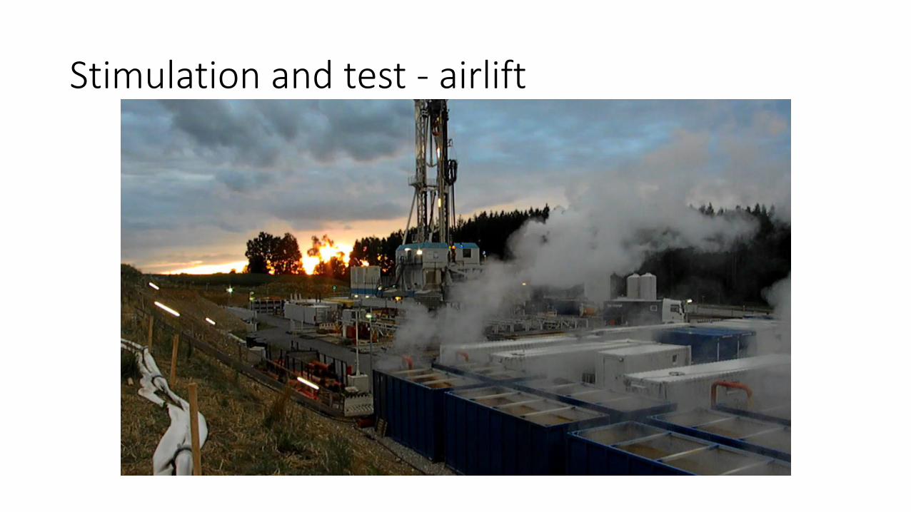
Stimulation and test - airliftCompressed air decreases the density of the water – air mixture so as to allow for the mixture to flow out of the well head
Stimulation and test - airlift

Stimulation and test – Gelfrac fluid with proppants

Stimulation and test –water frac with 6 pumps

Costs