service manual - the place for plumbing, heating, kitchen ... service manual.pdf · mh080fxca4a :...
TRANSCRIPT
SERVICEAIR CONDITIONER
FREE JOINT MULTI AIR CONDITIONERINDOOR UNIT OUTDOOR UNIT MH026FNCA MH050FXCA2A MH035FNCA MH080FXCA4A MH052FNCA MH026FECA MH035FECA MH052FECA
Manual
THE FEATURE OF PRODUCT
■ Multi Inverter(Free Joint Multi) Series – Variable Indoor Unit Combination(Free Joint Multi) – Multi Inverter(Free Joint Multi) Series delivers
comfort to 2~4 rooms with a Single Outdoor Unit – Smart & Low noise outdoor units in any condition.
■ Energy Saving – High Efficiency DC inverter and BLDC Comp. – Smart Inverter Control algorithm. – TBR Sine-Wave Compressor & Sine Wave Controller.
■ Convenient Installation – 485 non Polarity / Auto addressing – Easy checking system condition by 7-segment
■ Space Saving & Environmental Friendly – Compact & Light Outdoor Unit – Slim and Quiet Indoor Units
Refer to the service manual in the GSPN(see the rear cover) for the more information.
Contents
1. Precautions .......................................................................................................................................... 1-11-1 Installing the air conditioner .......................................................................................................... 1-1
1-2 Power supply and circuit breaker .............................................................................................. 1-1
1-3 During operation ................................................................................................................................ 1-1
1-4 Disposing of the unit ........................................................................................................................ 1-2
1-5 Others..................................................................................................................................................... 1-2
2. Product Specifications ............................................................................................................. 2-12-1 The Feature of Product ................................................................................................................. 2-1
2-2 Product Specifications ................................................................................................................... 2-2
2-3 Accessory and Option Specifications ...................................................................................... 2-6
3. Alignment and Adjustments .............................................................................................. 3-13-1 Error mode and check method ................................................................................................... 3-1
3-2 Setting Option Setup Method ..................................................................................................... 3-6
4. Disassembly and Reassembly ........................................................................................ 4-14-1 Indoor Unit ........................................................................................................................................... 4-2
4-2 Outdoor Unit ....................................................................................................................................... 4-18
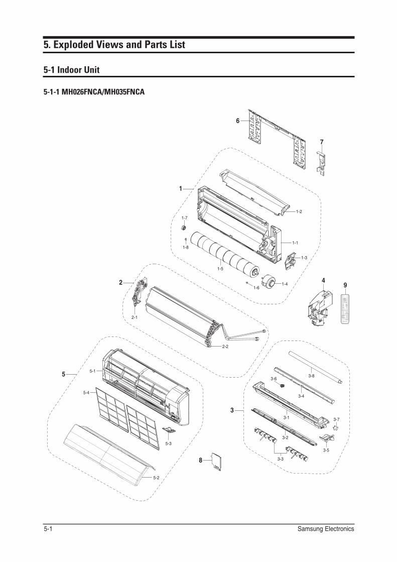
5. Exploded Views and Parts List ....................................................................................... 5-15-1 Indoor Unit ........................................................................................................................................... 5-1
5-2 Outdoor Unit ....................................................................................................................................... 5-9
6. Wiring Diagram ............................................................................................................................... 6-16-1 Indoor Unit ........................................................................................................................................... 6-1
6-2 Outdoor Unit ....................................................................................................................................... 6-3
7. Schematic Diagram ..................................................................................................................... 7-17-1 Indoor Unit ........................................................................................................................................... 7-1
7-2 Outdoor Unit ....................................................................................................................................... 7-3
8. PCB Diagram ..................................................................................................................................... 8-18-1 MAIN PCB(Indoor Unit) ................................................................................................................. 8-1
8-2 MAIN PCB(Outdoor Unit) ............................................................................................................. 8-4
Contents
9. Troubleshooting .............................................................................................................................. 9-19-1 Items to be checked first ................................................................................................................ 9-1
9-2 Checking and Testing operations ............................................................................................... 9-2
9-3 Fault Diagnosis by Symptom ....................................................................................................... 9-12
9-4 PCB Inspection................................................................................................................................... 9-18
10. Reference for Installation....................................................................................................... 10-110-1 Selecting Area for Installation.................................................................................................... 10-1
10-2 Connecting Up and Purging the Circuit................................................................................. 10-3
10-3 Refrigerant Refill.............................................................................................................................. 10-5
10-4 Refrigerant Adjustment................................................................................................................. 10-7
10-5 Flare Nut Fixing Torque................................................................................................................ 10-8
10-6 "Pump down" Procedure.............................................................................................................. 10-9
11. Reference Information............................................................................................................... 11-111-1 Index for Model Name ................................................................................................................. 11-1
11-2 Refrigerating Cycle Diagram ..................................................................................................... 11-3
11-3 Pressure & Capacity mark ......................................................................................................... 11-5
11-4 The abbreviated technology words & the definition of technology terms .............. 11-5
11-5 Q & A for Non-trouble ................................................................................................................... 11-6
11-6 Common sense of refrigeration ............................................................................................... 11-9
1. Precautions
1-1 Installing the air conditioner
● Users should not install the air conditioner by themselves. Ask the dealer or authorized company to install the air conditioner except the window-type air conditioner in U.S.A and Canada.
● If you don’t install the air conditioner properly, it may cause a fire, a water leakage or an electric shock. ● You must install the air conditioner according to the national wiring regulations and safety regulations. ● Install the indoor unit higher than 8.2ft(2.5m) from the floor to avoid the injury caused by the operation of the fan.
(except the window-type air conditioner) ● The manufacturer is not responsible for any accidents or injury caused by an incorrect installation. ● When installing the built-in type air conditioner, keep all electric cables such as the power cable and the connection cord in pipes,
ducts, or cable channels to protect them from the danger of impact or any other incidents. ● More than 2 indoor units should be installed when you use Free Joint Multi air conditioner. ● MH050FXCA2A
- MH052FNCA and MH052FECA indoor unit cannot be connected to the MH050FXCA2A outdoor unit.
1-2 Power supply and circuit breaker
● If the power cord of the air conditioner is damaged, it must be replaced by the manufacturer or a qualified person in order to avoid a hazard.
● The air conditioner must be plugged into an independent circuit if applicable or connect the power cable to the auxiliary circuit breaker. An all pole disconnection from the power supply must be incorporated in the fixed wiring with a contact opening of >0.12inch(mm).
● Do not extend an electric cord to the air conditioner. ● The air conditioner must be plugged in after you complete the installation.
1-3 During operation
● Do not repair the air conditioner at your discretion. It is recommended to contact a service center directly.
● Never spill any kind of liquid on the air conditioner. If this happens, turn off the air conditioner and contact an authorized service center.
● Do not insert anything between the airflow blades to prevent damage of the inner fan and consequent injury. Keep children away from the air conditioner.
● Do not place any obstacles in front of the air conditioner. ● Do not spray any kind of liquid into the indoor unit. If this happens, turn off the air conditioner and contact a service center. ● Make sure that the air conditioner is well ventilated at all times:
Do not place a cloth or other materials over it. ● Remove the batteries if you don’t use the remote control for a long time. (If applicable) ● Use the remote control within 23ft(7m) from the indoor unit. (If applicable)
Samsung Electronics 1-1
1-4 Disposing of the unit
● Before throwing out the air conditioner, remove the batteries from the remote control. ● When you dispose of the air conditioner, consult your dealer. If pipes are removed incorrectly, refrigerant may blow out and
cause air pollution. When it contacts with your skin, it can cause skin injury. ● The package of the air conditioner should be recycled or disposed of properly for environmental reasons.
1-5 Others
● Never store or load the air conditioner upside down or sideways to prevent the damage to the compressor. ● Young children or infirm persons should be always supervised when they use the air conditioner. ● Max current is measured according to IEC standard for safety. ● Current is measured according to ISO standard for energy efficiency.
Samsung Electronics 1-2

2. Product Specifications
2-1 The Feature of Product
■ Multi Inverter(Free Joint Multi) Series delivers comfort to 2~4 rooms with a Single Outdoor Unit.
■ Inverter for High Efficiency Operation. Thanks to inverter control, efficiency of operation of the outdoor unit is enhanced depending on the number of indoor units operated and the temperature setting.When only one indoor unit is used, power is saved, resulting in a smaller electricity bill. When all indoor units are used, high-power operation achieves comfort quickly in all rooms.
■ Installation of indoor units on different floors is possible.
■ Convenient Installation Auto addressing option : Automated checking of pipe connection.(Refer to the installation manual for detail)
■ Space saving & Environmental Friendly • Compact & light outdoor unit • Slim and quiet indoor units • Pipe size reduction • Ozone friendly Refrigerant(R410A) • Lead Free controller.
■ Reliability • Installation possibilities(Length/Height) • Convenient installation(485 non polarity/auto-addressing) • Intelligent control/network • Easy checking system condition by 7-segment
■ Smart & Low Noise outdoor units in any condition • TBR/Sine-Wave Controller/Noise Reduction Control/Dual Felt etc. • Felt Structure : New felt has selected to reduce the noise coming out of the compressor.
Double layered felt structure absorbs noise by two times and felt is also covering top of the compressor to reduce the noise even more.
Samsung Electronics 2-1
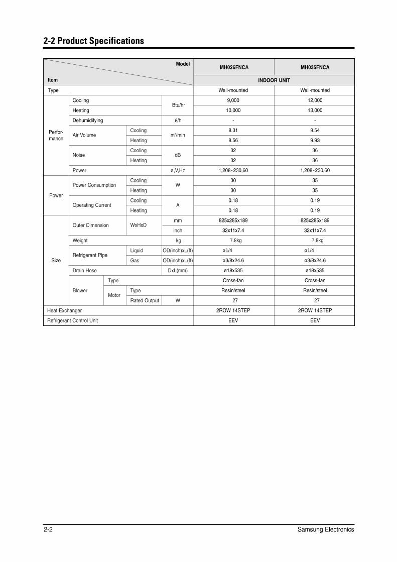
2-2 Product Specifications
Model MH026FNCA MH035FNCA
Item INDOOR UNIT
Type Wall-mounted Wall-mounted
Cooling 9,000 12,000
Perfor-
Heating Btu/hr
10,000 13,000
Dehumidifying |/h - -
Air Volume Cooling
m3/min 8.31 9.54
mance Heating 8.56 9.93
Noise Cooling
dB 32 36
Heating 32 36
Power ø,V,Hz 1,208~230,60 1,208~230,60
Power Consumption Cooling
W 30 35
Power Heating 30 35
Operating Current Cooling
A 0.18 0.19
Heating 0.18 0.19
Size
Outer Dimension WxHxD mm 825x285x189 825x285x189
inch 32x11x7.4 32x11x7.4
Weight kg 7.8kg 7.8kg
Refrigerant Pipe Liquid OD(inch)xL(ft) ø1/4 ø1/4
Gas OD(inch)xL(ft) ø3/8x24.6 ø3/8x24.6
Drain Hose DxL(mm) ø18x535 ø18x535
Blower
Type Cross-fan Cross-fan
Motor Type Resin/steel Resin/steel
Rated Output W 27 27
Heat Exchanger 2ROW 14STEP 2ROW 14STEP
Refrigerant Control Unit EEV EEV
Samsung Electronics 2-2
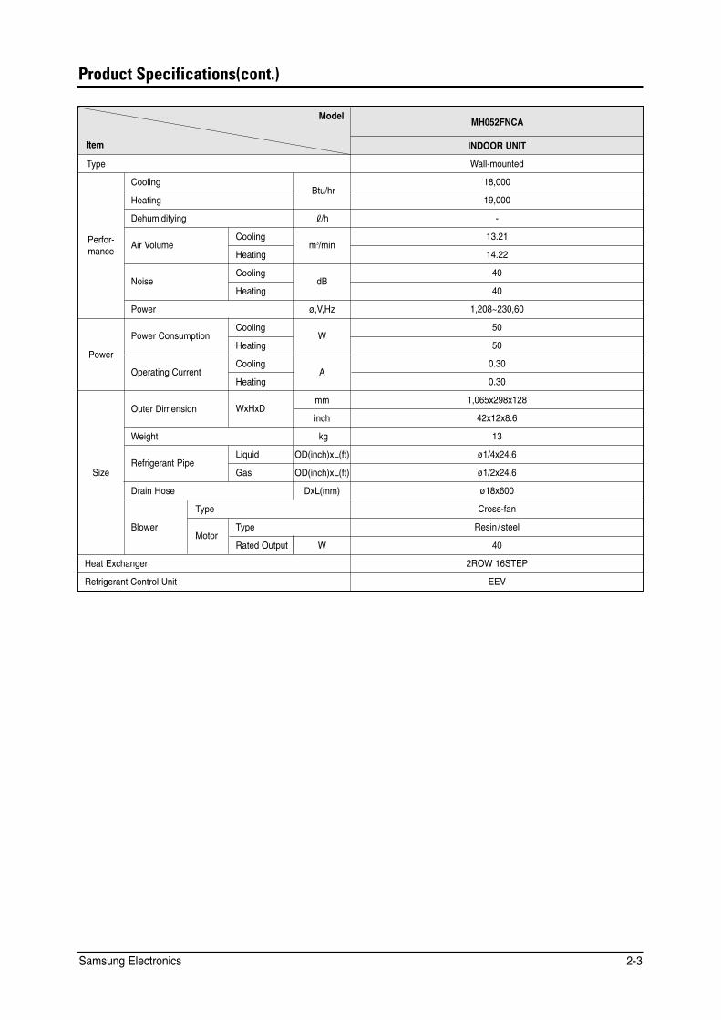
Product Specifications(cont.)
Model MH052FNCA
Item INDOOR UNIT
Type Wall-mounted
Cooling 18,000
Perfor-
Heating Btu/hr
19,000
Dehumidifying |/h -
Air Volume Cooling
m3/min 13.21
mance Heating 14.22
Noise Cooling
dB 40
Heating 40
Power ø,V,Hz 1,208~230,60
Power Consumption Cooling
W 50
Power Heating 50
Operating Current Cooling
A 0.30
Heating 0.30
Size
Outer Dimension WxHxD mm 1,065x298x128
inch 42x12x8.6
Weight kg 13
Refrigerant Pipe Liquid OD(inch)xL(ft) ø1/4x24.6
Gas OD(inch)xL(ft) ø1/2x24.6
Drain Hose DxL(mm) ø18x600
Blower
Type Cross-fan
Motor Type Resin /steel
Rated Output W 40
Heat Exchanger 2ROW 16STEP
Refrigerant Control Unit EEV
Samsung Electronics 2-3
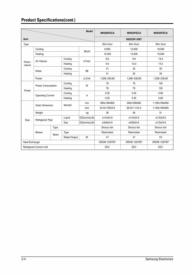
Product Specifications(cont.)
Model MH026FECA MH035FECA MH052FECA
Item INDOOR UNIT
Type Slim Duct Slim Duct Slim Duct
Cooling Btu/hr
9,000 12,000 18,000
Performance
Heating 10,000 13,000 19,000
Air Volume Cooling
m3/min 8.6 9.8 13.6
Heating 9.0 10.3 14.2
Noise Cooling
dB 31 32 39
Heating 31 32 39
Power ø,V,Hz 1,208~230,60 1,208~230,60 1,208~230,60
Power Consumption Cooling
W 76 76 150
Power Heating 76 76 150
Operating Current Cooling
A 0.35 0.35 0.69
Heating 0.35 0.35 0.69
Size
Outer Dimension WxHxD mm 900x199x600 900x199x600 1,100x199x600
inch 35.4x7.8X23.6 38.2x7.1x15.4 1,100x199x600
Weight kg 26 26 31
Refrigerant Pipe Liquid OD(inch)xL(ft) ø1/4x24.6 ø1/4x24.6 ø1/4x24.6
Gas OD(inch)xL(ft) ø3/8x24.6 ø3/8x24.6 ø1/2x24.6
Blower
Type Sirocco fan Sirocco fan Sirocco fan
Motor Type Resin/steel Resin/steel Resin/steel
Rated Output W 47 47 53
Heat Exchanger 2ROW 12STEP 2ROW 12STEP 2ROW 12STEP
Refrigerant Control Unit EEV EEV EEV
Samsung Electronics 2-4
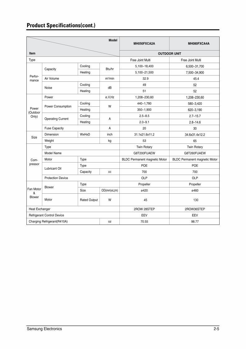
Product Specifications(cont.)
/QFGN /*���(:&#�$ /*���(:%#�#
+VGO 176&114�70+6
6[RG (TGG�,QKPV�/WNVK (TGG�,QKPV�/WNVK
%QQNKPI $VW�JT
�����`������ �����`������
2GTHQT� OCPEG
%CRCEKV[ *GCVKPI �����`������ �����`������
#KT�8QNWOG O��OKP ���� ����
%QQNKPI F$
�� �� 0QKUG
*GCVKPI �� ��
2QYGT �8�*\ �����`������ �����`������
%QQNKPI 9
���`����� ���`����� 2QYGT 1WVFQQT 1PN[�
2QYGT�%QPUWORVKQP *GCVKPI ���`����� ���`�����
1RGTCVKPI�%WTTGPV %QQNKPI
# ���`��� ���`����
*GCVKPI ���`��� ���`����
(WUG�%CRCEKV[ # �� ��
5K\G &KOGPUKQP 9Z*Z& KPEJ ����Z����Z���� ����Z����Z����
9GKIJV MI �� ��
%QO� RTGUUQT
6[RG 6YKP�4QVCT[ 6YKP�4QVCT[
/QFGN�0COG )�6���(7#'9 )�6���(7#'9
/QVQT 6[RG $.&%�2GTOCPGPV�OCIPGVKE�/QVQT $.&%�2GTOCPGPV�OCIPGVKE�/QVQT
.WDTKECPV�1KN 6[RG 21' 21'
%CRCEKV[ EE ��� ���
2TQVGEVKQP�&GXKEG 1.2 1.2
(CP�/QVQT �
$NQYGT
$NQYGT 6[RG 2TQRGNNGT 2TQRGNNGT
5K\G 1&OO�Z.O� ��� ���
/QVQT 4CVGF�1WVRWV 9 �� ���
*GCV�'ZEJCPIGT �419���56'2 �419��56'2
4GHTKIGTCPV�%QPVTQN�&GXKEG ''8 ''8
%JCTIKPI�4GHTKIGTCPV4���#� Q\ ����� �����
Samsung Electronics 2-5
Samsung Electronics2-6
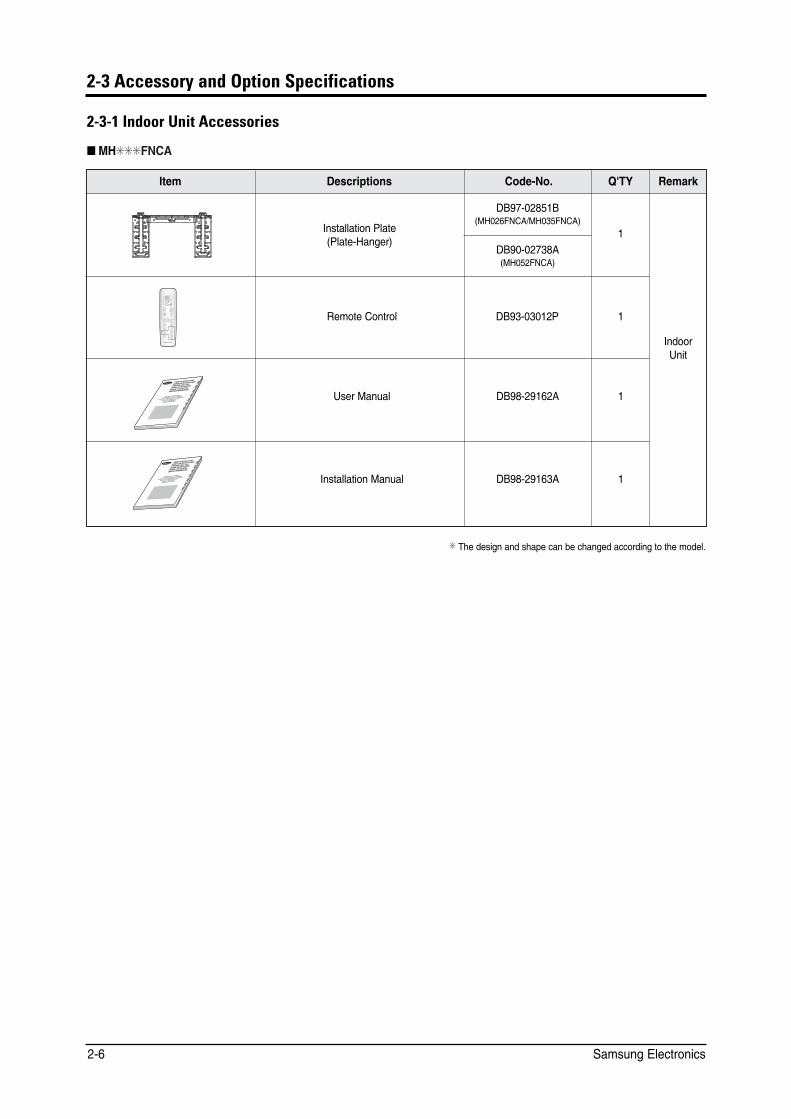
2-3 Accessory and Option Specifications
2-3-1 Indoor Unit Accessories
■ MH✳✳✳FNCA
+VGO &GUETKRVKQPU 36;%QFG�0Q� 4GOCTM
+PFQQT7PKV
�
4GOQVG�%QPVTQN �
7UGT�/CPWCN &$��������# �
+PUVCNNCVKQP�/CPWCN &$��������# �
&$��������$/*���(0%#�/*���(0%#�
&$��������#/*���(0%#�
&$��������3
6JG�FGUKIP�CPF�UJCRG�ECP�DG�EJCPIGF�CEEQTFKPI�VQ�VJG�OQFGN�
+PUVCNNCVKQP�2NCVG2NCVG�*CPIGT�
190'45 +05647%6+105
/#07#. &' +05647%%+10'5
+5647<+10+ 2'4 .751
/#07#. &' +05647�¨'5
/#07'. &76+.+5#6+10
)'$4#7%*5#09'+570)
5RNWV�V[RG 4QQO #KT %QPFKVKQPGT
#KTG CEQPFKEKQPCFQFQOÃUVKEQ UKUVGOC
5RNKV
%QPFK\KQPCVQTG FCTKC RGT CODKGPVK CF
WPKV´ 5GRCTCVG
#RCTGNJQ FG CT EQPFKEKQPCFQ VKRQ 5RNK
V
%NKOCVKUGWT FG V[RGUÃRCTÃ
)GVGKNVG TCWOMNKOCCPNCIG
2-7Samsung Electronics
Product Specifications
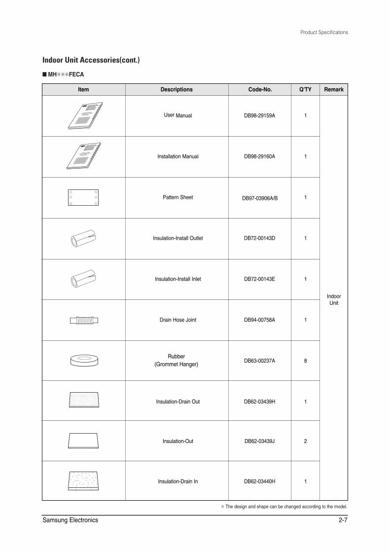
✳ The design and shape can be changed according to the model.
Indoor Unit Accessories(cont.)
■ MH✳✳✳FECA
Item Descriptions Q'TYCode-No. Remark
IndoorUnit
User Manual DB98-29159A 1
Installation Manual DB98-29160A 1
Pattern Sheet 1
Insulation-Install Outlet DB72-00143D 1
Insulation-Install Inlet DB72-00143E 1
Drain Hose Joint DB94-00758A 1
DB63-00237A 8
Insulation-Drain Out DB62-03439H 1
Insulation-Out DB62-03439J 2
Insulation-Drain In DB62-03440H 1
OWNER'S INSTRUCTIONS
MANUAL DE INSTRUCCIONES
ISTRUZIONI PER L'USO
MANUAL DE INSTRUÇÕES
MANUEL D'UTILISATION
GEBRAUCHSANWEISUNG
Splut-type Room Air Conditioner
Aire acondicionado doméstico sistema Split
Condizionatore d'aria per ambienti ad unità Separate
Aparelho de ar condicionado tipo Split
Climatiseur de type séparé
Geteilte raumklimaanlage
DB97-03906A/B
Rubber(Grommet Hanger)

Product Specifications
Indoor Unit Accessories(cont.)
■ MH✳✳✳FECA(cont.)
Item Descriptions Code-No. Q'TY Remark
Cable-tie DB65-10088C 8
Indoor Unit
Drain Pipe Holder DB90-02064A 2
✳ The design and shape can be changed according to the model.
Samsung Electronics 2-8
2-9Samsung Electronics
Product Specifications
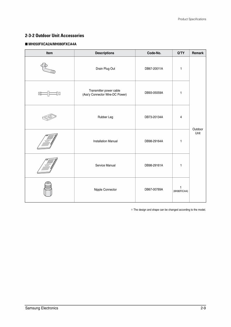
+VGO &GUETKRVKQPU 36;%QFG�0Q� 4GOCTM
1WVFQQT7PKV
&TCKP�2NWI�1WV &$��������# �
�
4WDDGT�.GI &$��������# �
+PUVCNNCVKQP�/CPWCN &$��������# �
5GTXKEG�/CPWCN &$��������# �
0KRRNG�%QPPGEVQT &$��������#
6TCPUOKVVGT�RQYGT�ECDNG#UU[�%QPPGEVQT�9KTG�&%�2QYGT� &$��������#
6JG�FGUKIP�CPF�UJCRG�ECP�DG�EJCPIGF�CEEQTFKPI�VQ�VJG�OQFGN�
190'45 +05647%6+105
/#07#. &' +05647%%+10'5
+5647<+10+ 2'4 .751
/#07#. &' +05647�¨'5
/#07'. &76+.+5#6+10
)'$4#7%*5#09'+570)
)'$4#7%*5#09'+570)
)'$4#7%*5#09'+570)
5RNWV�V[RG 4QQO #KT %QPFKVKQPGT
#KTG CEQPFKEKQPCFQFQOÃUVKEQ UKUVGOC
5RNKV
%QPFK\KQPCVQTG FCTKC RGT CODKGPVK CF
WPKV´ 5GRCTCVG
#RCTGNJQ FG CT EQPFKEKQPCFQ VKRQ 5RNK
V
%NKOCVKUGWT FG V[RGUÃRCTÃ
)GVGKNVG TCWOMNKOCCPNCIG
)GVGKNVG TCWOMNKOCCPNCIG
�/*���(:%#�#�
2-3-2 Outdoor Unit Accessories
■ MH050FXCA2A/MH080FXCA4A
Product Specifications
Samsung Electronics2-10
Item Descriptions Q'TYCode-No. Remark
Transmitter
OWNER'S INSTRUCTIONS
MANUAL DE INSTRUCCIONES
ISTRUZIONI PER L'USO
MANUAL DE INSTRUÇÕES
MANUEL D'UTILISATION
GEBRAUCHSANWEISUNG
GEBRAUCHSANWEISUNG
GEBRAUCHSANWEISUNG
Splut-type Room Air Conditioner
Aire acondicionado doméstico sistema Split
Condizionatore d'aria per ambienti ad unità Separate
Aparelho de ar condicionado tipo Split
Climatiseur de type séparé
Geteilte raumklimaanlage
Geteilte raumklimaanlage
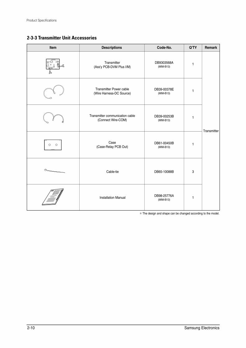
2-3-3 Transmitter Unit Accessories
1
1
1
1
Cable-tie DB65-10088B 3
Installation Manual 1
✳ The design and shape can be changed according to the model.
Transmitter(Ass'y PCB-DVM Plus I/M)
Transmitter Power cable(Wire Harness-DC Source)
Transmitter communication cable(Connect Wire-COM)
Case(Case-Relay PCB Out)
DB9303568A(MIM-B13)
DB39-00378E(MIM-B13)
DB39-00253B(MIM-B13)
DB98-25776A(MIM-B13)
DB61-00450B(MIM-B13)
����HECJIAJP�=J@��@FQOPIAJPO
����"NNKN�IK@A�=J@�?DA?G�IAPDK@
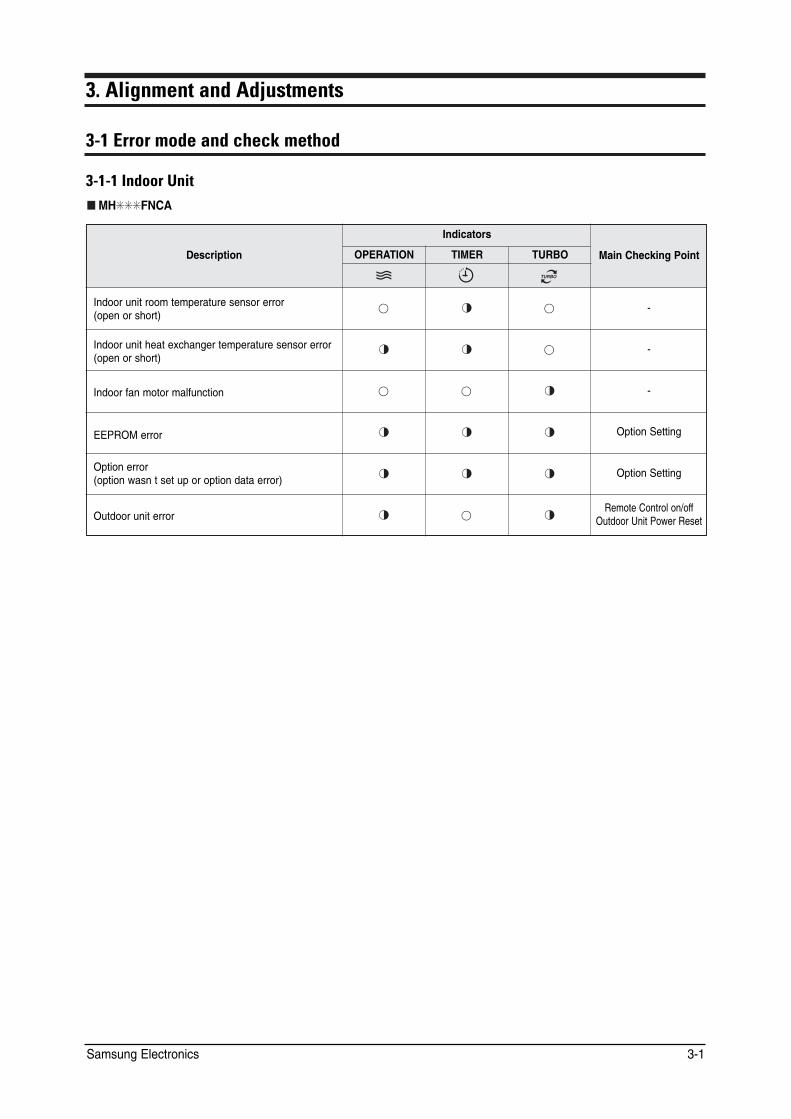
������&J@KKN�2JEP /* (0%#
&GUETKRVKQP
+PFKECVQTU
/CKP�%JGEMKPI�2QKPV 12'4#6+10 6+/'4 674$1
+PFQQT�WPKV�TQQO�VGORGTCVWTG�UGPUQT�GTTQT QRGP�QT�UJQTV��
�
+PFQQT�WPKV�JGCV�GZEJCPIGT�VGORGTCVWTG�UGPUQT�GTTQT QRGP�QT�UJQTV��
�
+PFQQT�HCP�OQVQT�OCNHWPEVKQP �
''241/�GTTQT� 1RVKQP�5GVVKPI
1RVKQP�GTTQT QRVKQP�YCUP�V�UGV�WR�QT�QRVKQP�FCVC�GTTQT��
1RVKQP�5GVVKPI
1WVFQQT�WPKV�GTTQT 4GOQVG�%QPVTQN�QP�QHH
1WVFQQT�7PKV�2QYGT�4GUGV
Samsung Electronics 3-1
Alignment and Adjustments
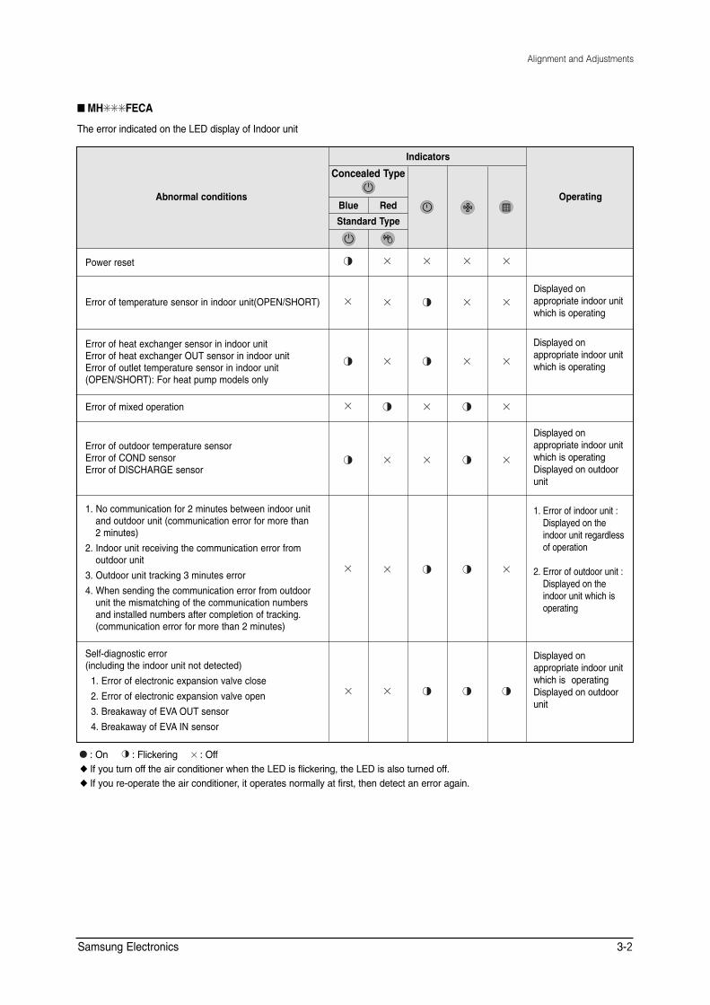
■ MH✳✳✳FECA
The error indicated on the LED display of Indoor unit
Abnormal conditions
Indicators
Operating
Concealed Type
Blue Red
Standard Type
Power reset
Error of temperature sensor in indoor unit(OPEN/SHORT) Displayed on appropriate indoor unit which is operating
Error of heat exchanger sensor in indoor unit Error of heat exchanger OUT sensor in indoor unit Error of outlet temperature sensor in indoor unit (OPEN/SHORT): For heat pump models only
Displayed on appropriate indoor unit which is operating
Error of mixed operation
Error of outdoor temperature sensor Error of COND sensor Error of DISCHARGE sensor
Displayed on appropriate indoor unit which is operating Displayed on outdoor unit
1. No communication for 2 minutes between indoor unit and outdoor unit (communication error for more than 2 minutes)
2. Indoor unit receiving the communication error from outdoor unit
3. Outdoor unit tracking 3 minutes error
4. When sending the communication error from outdoor unit the mismatching of the communication numbers and installed numbers after completion of tracking. (communication error for more than 2 minutes)
1. Error of indoor unit : Displayed on the indoor unit regardless of operation
2. Error of outdoor unit : Displayed on the indoor unit which is operating
Self-diagnostic error (including the indoor unit not detected)
1. Error of electronic expansion valve close
2. Error of electronic expansion valve open
3. Breakaway of EVA OUT sensor
4. Breakaway of EVA IN sensor
Displayed on appropriate indoor unit which is operating Displayed on outdoor unit
: On : Flickering : Off ◆ If you turn off the air conditioner when the LED is flickering, the LED is also turned off. ◆ If you re-operate the air conditioner, it operates normally at first, then detect an error again.
Samsung Electronics 3-2
Alignment and Adjustments
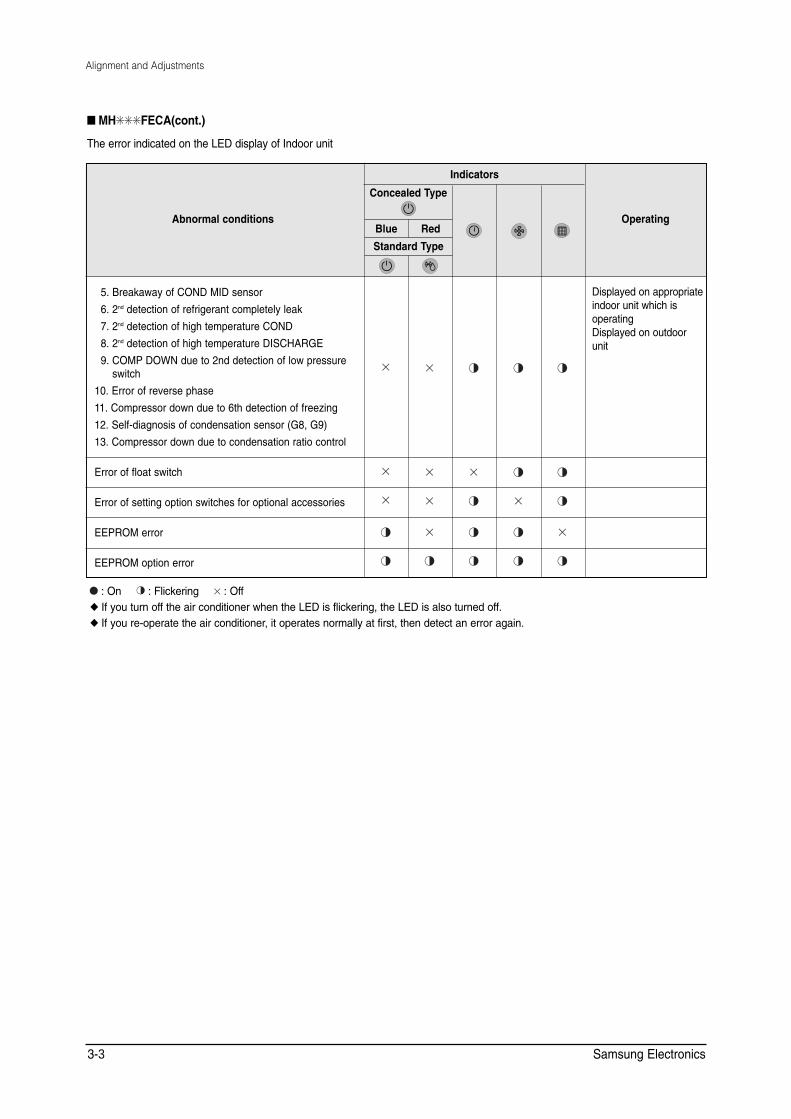
■ MH✳✳✳FECA(cont.)
The error indicated on the LED display of Indoor unit
Abnormal conditions
Indicators
Operating
Concealed Type
Blue Red
Standard Type
5. Breakaway of COND MID sensor
6. 2nd detection of refrigerant completely leak
7. 2nd detection of high temperature COND
8. 2nd detection of high temperature DISCHARGE
9. COMP DOWN due to 2nd detection of low pressure switch
10. Error of reverse phase
11. Compressor down due to 6th detection of freezing
12. Self-diagnosis of condensation sensor (G8, G9)
13. Compressor down due to condensation ratio control
Displayed on appropriate indoor unit which is operating Displayed on outdoor unit
Error of float switch
Error of setting option switches for optional accessories
EEPROM error
EEPROM option error
: On : Flickering : Off ◆ If you turn off the air conditioner when the LED is flickering, the LED is also turned off. ◆ If you re-operate the air conditioner, it operates normally at first, then detect an error again.
Samsung Electronics 3-3
Alignment and Adjustments
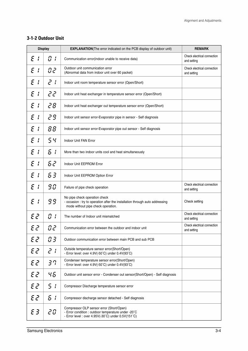
3-1-2 Outdoor Unit
Display EXPLANATION(The error indicated on the PCB display of outdoor unit) REMARK
Communication error(indoor unable to receive data) Check electrical connection and setting
Outdoor unit communication error (Abnormal data from indoor unit over 60 packet)
Check electrical connection and setting
Indoor unit room temperature sensor error (Open/Short)
Indoor unit heat exchanger in temperature sensor error (Open/Short)
Indoor unit heat exchanger out temperature sensor error (Open/Short)
Indoor unit sensor error-Evaporator pipe in sensor - Self diagnosis
Indoor unit sensor error-Evaporator pipe out sensor - Self diagnosis
Indoor Unit FAN Error
More than two indoor units cool and heat simultaneously
Indoor Unit EEPROM Error
Indoor Unit EEPROM Option Error
Failure of pipe check operation Check electrical connection and setting
No pipe check operation check - occasion : try to operation after the installation through auto addressing
mode without pipe check operation. Check setting
The number of Indoor unit mismatched Check electrical connection and setting
Communication error between the outdoor and indoor unit Check electrical connection and setting
Outdoor communication error between main PCB and sub PCB
Outside temperature sensor error(Short/Open) - Error level: over 4.9V(-50˚C) under 0.4V(93˚C)
Condenser temperature sensor error(Short/Open) - Error level: over 4.9V(-50˚C) under 0.4V(93˚C)
Outdoor unit sensor error - Condenser out sensor(Short/Open) - Self diagnosis
Compressor Discharge temperature sensor error
Compressor discharge sensor detached - Self diagnosis
Compressor OLP sensor error (Short/Open) - Error condition : outdoor temperature under -20˚C - Error level : over 4.95V(-30˚C) under 0.5V(151˚C)
Samsung Electronics 3-4
Alignment and Adjustments
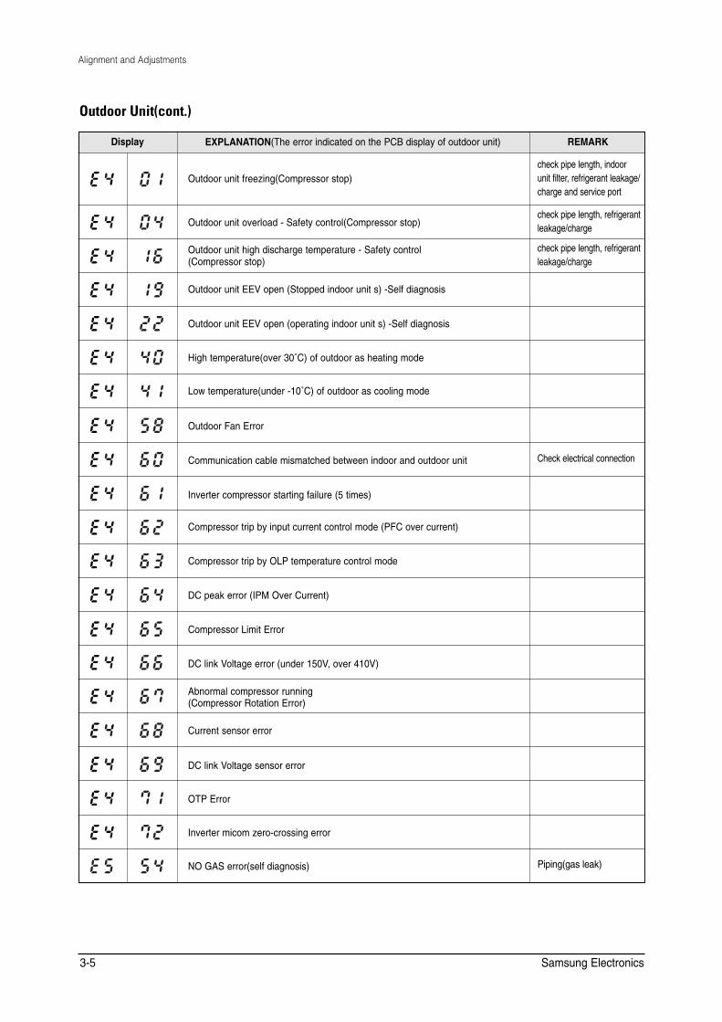
Outdoor Unit(cont.)
Display EXPLANATION(The error indicated on the PCB display of outdoor unit) REMARK
Outdoor unit freezing(Compressor stop) check pipe length, indoor unit filter, refrigerant leakage/ charge and service port
Outdoor unit overload - Safety control(Compressor stop) check pipe length, refrigerant leakage/charge
Outdoor unit high discharge temperature - Safety control (Compressor stop)
check pipe length, refrigerant leakage/charge
Outdoor unit EEV open (Stopped indoor unit s) -Self diagnosis
Outdoor unit EEV open (operating indoor unit s) -Self diagnosis
High temperature(over 30˚C) of outdoor as heating mode
Low temperature(under -10˚C) of outdoor as cooling mode
Outdoor Fan Error
Communication cable mismatched between indoor and outdoor unit Check electrical connection
Inverter compressor starting failure (5 times)
Compressor trip by input current control mode (PFC over current)
Compressor trip by OLP temperature control mode
DC peak error (IPM Over Current)
Compressor Limit Error
DC link Voltage error (under 150V, over 410V)
Abnormal compressor running (Compressor Rotation Error)
Current sensor error
DC link Voltage sensor error
OTP Error
Inverter micom zero-crossing error
NO GAS error(self diagnosis) Piping(gas leak)
Samsung Electronics 3-5

3-2 Setting Option Setup Method
ex) Option No. :
Step 1 : Enter the Option Setup mode.
1st Take out the batteries of remote control.
2nd Press the temperature button simultaneously and insert the battery again.
3rd Make sure the remocon display shown as .
Step 2 : Enter the Option Setup mode and select your option according to the following procedure.
Feature Display
3
1,4 2,5
Setting Option SEG1.
Push the button to set the display panel to .
Every time you push the button, the display panel reads . . . repeatedly.
2 Setting Option SEG2.
Push the button to set the display panel to .
Every time you push the button, the display panel reads . . . repeatedly.
4 Setting Option SEG3.
Push the button to set the display panel to .
Every time you push the button, the display panel reads . . . repeatedly.
3 Change it into the set display of Option SEG3 and SEG4
with the button.
5 Setting Option SEG4.
Push the button to set the display panel to .
Every time you push the button, the display panel reads . . . repeatedly.
1
Samsung Electronics 3-6

Alignment and Adjustments
Feature Display
6 Change it into the set display of Option SEG5 and SEG6
with the button.
7 Setting Option SEG5.
Push the button to set the display panel to .
Every time you push the button, the display panel reads . . . repeatedly.
8 Setting Option SEG6.
Push the button to set the display panel to .
Every time you push the button, the display panel reads . . . repeatedly.
6,9 9
Change it into the set display of Option SEG7 and SEG87,10 8,11 with the button.
10 Setting Option SEG7.
Push the button to set the display panel to .
Every time you push the button, the display panel reads . . . repeatedly.
11 Setting Option SEG8.
Push the button to set the display panel to .
Every time you push the button, the display panel reads . . . repeatedly.
12 Change it into the set display of Option SEG9 and SEG10
with the button. 12
13 14 13 Setting Option SEG9.
Push the button to set the display panel to .
Every time you push the button, the display panel reads . . . repeatedly.
14 Setting Option SEG10.
Push the button to set the display panel to .
Every time you push the button, the display panel reads . . . repeatedly.
3-7 Samsung Electronics
Alignment and Adjustments
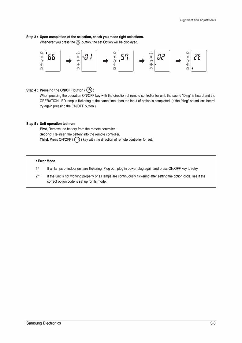
Step 3 : Upon completion of the selection, check you made right selections. Whenever you press the button, the set Option will be displayed.
Step 4 : Pressing the ON/OFF button ( ) When pressing the operation ON/OFF key with the direction of remote controller for unit, the sound "Ding" is heard and the OPERATION LED lamp is flickering at the same time, then the input of option is completed. (If the "ding" sound isn't heard, try again pressing the ON/OFF button.)
Step 5 : Unit operation test-run First, Remove the battery from the remote controller. Second, Re-insert the battery into the remote controller. Third, Press ON/OFF ( ) key with the direction of remote controller for set.
• Error Mode
1st If all lamps of indoor unit are flickering, Plug out, plug in power plug again and press ON/OFF key to retry.
2nd If the unit is not working properly or all lamps are continuously flickering after setting the option code, see if the correct option code is set up for its model.
Samsung Electronics 3-8
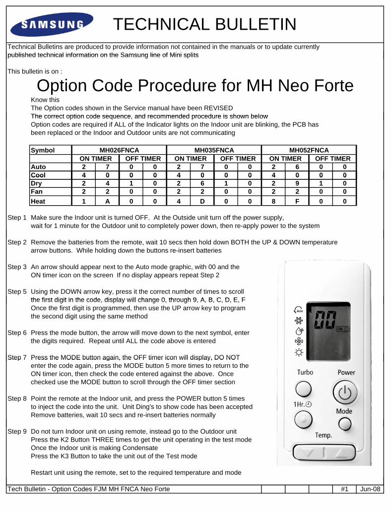
TECHNICAL BULLETIN Technical Bulletins are produced to provide information not contained in the manuals or to update currently published technical information on the Samsung line of Mini splitspublished technical information on the Samsung line of Mini splits
This bulletin is on :
Know this The Option codes shown in the Service manual have been REVISED The correct option code sequence and recommended procedure is shown below
Option Code Procedure for MH Neo Forte The correct option code sequence, and recommended procedure is shown below Option codes are required if ALL of the Indicator lights on the Indoor unit are blinking, the PCB has been replaced or the Indoor and Outdoor units are not communicating
Symbol
Auto 2 7 0 0 2 7 0 0 2 6 0 0 Cool 4 0 0 0 4 0 0 0 4 0 0 0
MH026FNCA MH035FNCA MH052FNCA ON TIMER OFF TIMERON TIMER OFF TIMER ON TIMER OFF TIMER
Cool 4 0 0 0 4 0 0 0 4 0 0 0 Dry 2 4 1 0 2 6 1 0 2 9 1 0 Fan 2 2 0 0 2 2 0 0 2 2 0 0 Heat 1 A 0 0 4 D 0 0 8 F 0 0
Step 1 Make sure the Indoor unit is turned OFF. At the Outside unit turn off the power supply, wait for 1 minute for the Outdoor unit to completely power down, then re-apply power to the system
Step 2 Remove the batteries from the remote, wait 10 secs then hold down BOTH the UP & DOWN temperature arrow buttons. While holding down the buttons re-insert batteries
Step 3 An arrow should appear next to the Auto mode graphic, with 00 and the ON timer icon on the screen If no display appears repeat Step 2
Step 5 Using the DOWN arrow key, press it the correct number of times to scroll the first digit in the code display will change 0 through 9 A B C D E F the first digit in the code, display will change 0, through 9, A, B, C, D, E, F Once the first digit is programmed, then use the UP arrow key to program the second digit using the same method
Step 6 Press the mode button, the arrow will move down to the next symbol, enter the digits required. Repeat until ALL the code above is entered
Step 7 Press the MODE button again, the OFF timer icon will display, DO NOTStep 7 Press the MODE button again, the OFF timer icon will display, DO NOT enter the code again, press the MODE button 5 more times to return to the ON timer icon, then check the code entered against the above. Once checked use the MODE button to scroll through the OFF timer section
Step 8 Point the remote at the Indoor unit, and press the POWER button 5 times to inject the code into the unit. Unit Ding's to show code has been accepted Remove batteries, wait 10 secs and re-insert batteries normally
Step 9 Do not turn Indoor unit on using remote, instead go to the Outdoor unit Press the K2 Button THREE times to get the unit operating in the test mode Once the Indoor unit is making Condensate Press the K3 Button to take the unit out of the Test mode
Restart unit using the remote, set to the required temperature and mode
Tech Bulletin - Option Codes FJM MH FNCA Neo Forte #1 Jun-08
Alignment and Adjustments
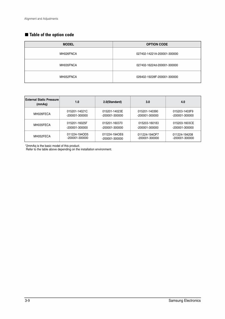
■ Table of the option code
MODEL OPTION CODE
MH026FNCA 027402-14221A-200001-300000
MH035FNCA 027402-16224d-200001-300000
MH052FNCA 026402-19228F-200001-300000
'ZVGTPCN�5VCVKE�2TGUUWTG OO#S�
��� ���5VCPFCTF� ��� ���
/*���('%# ������������& ��������������
������������( ��������������
������������� ��������������
�����������)� ��������������
/*���('%# ������������)
��������������
������������� ��������������
������������� ��������������
�����������&(
��������������
/*���('%# ����������1&� ��������������
����������2'� ��������������
����������1(� ��������������
������������� ��������������
��OO#S�KU�VJG�DCUKE�OQFGN�QH�VJKU�RTQFWEV� �4GHGT�VQ�VJG�VCDNG�CDQXG�FGRGPFKPI�QP�VJG�KPUVCNNCVKQP�GPXKTQPOGPV�
Samsung Electronics 3-9
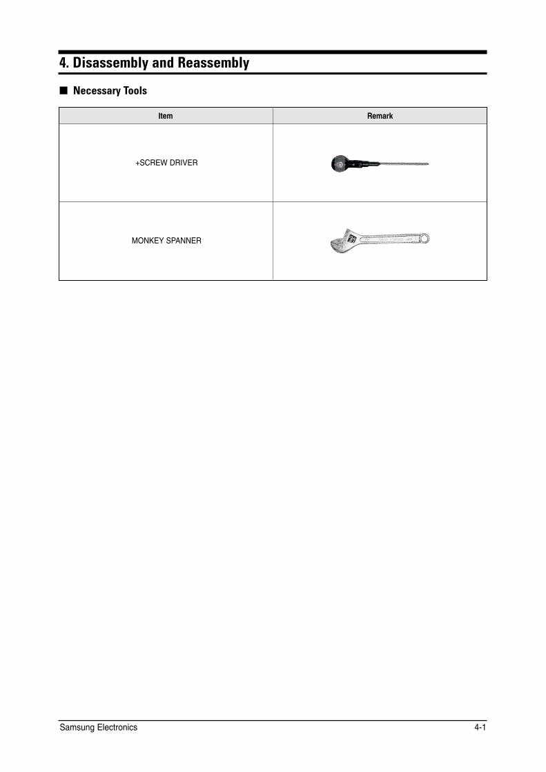
4. Disassembly and Reassembly
■ Necessary Tools
Item Remark
+SCREW DRIVER
MONKEY SPANNER
Samsung Electronics 4-1
4-1 Indoor Unit
Stop operation of the air conditioner and remove the power cord before repairing the unit.
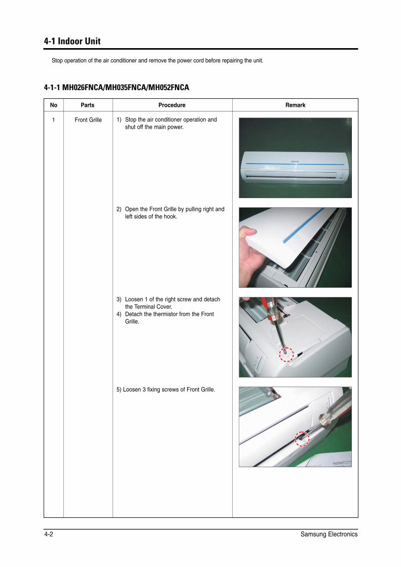
4-1-1 MH026FNCA/MH035FNCA/MH052FNCA
No Parts Procedure Remark
1 Front Grille 1) Stop the air conditioner operation and shut off the main power.
2) Open the Front Grille by pulling right and left sides of the hook.
3) Loosen 1 of the right screw and detach the Terminal Cover.
4) Detach the thermistor from the Front Grille.
5) Loosen 3 fixing screws of Front Grille.
Samsung Electronics 4-2

Disassembly and Reassembly
No Parts Procedure Remark
6) Unlock 3 hooks to fix Panel Front and Tray Drain.
7) Unlock 3 hooks to fix Panel Front and Back-Body.
2 Control-In (Main PCB)
1) Take all the connector of PCB upper side out. (Inclusion Power Cord)
2) Detach the outdoor unit connection wirefrom the Terminal Block.
3) Loosen 4 fixing screws of Ass’y Control-In.
3 Tray Drain 1) Pull Tray Drain out from the Back Body.
Samsung Electronics 4-3
Disassembly and Reassembly
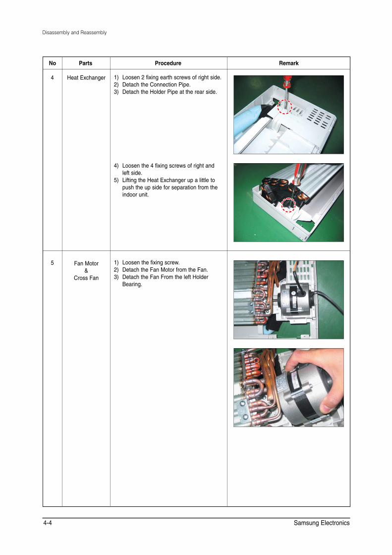
No Parts Procedure Remark
4 Heat Exchanger 1) Loosen 2 fixing earth screws of right side. 2) Detach the Connection Pipe. 3) Detach the Holder Pipe at the rear side.
4) Loosen the 4 fixing screws of right and left side.
5) Lifting the Heat Exchanger up a little to push the up side for separation from the indoor unit.
5 Fan Motor &
Cross Fan
1) Loosen the fixing screw. 2) Detach the Fan Motor from the Fan. 3) Detach the Fan From the left Holder
Bearing.
Samsung Electronics 4-4
Disassembly and Reassembly
4-1-2 MH026FECA/MH035FECA
No Parts Procedure Remark
1 Motor &
Blower
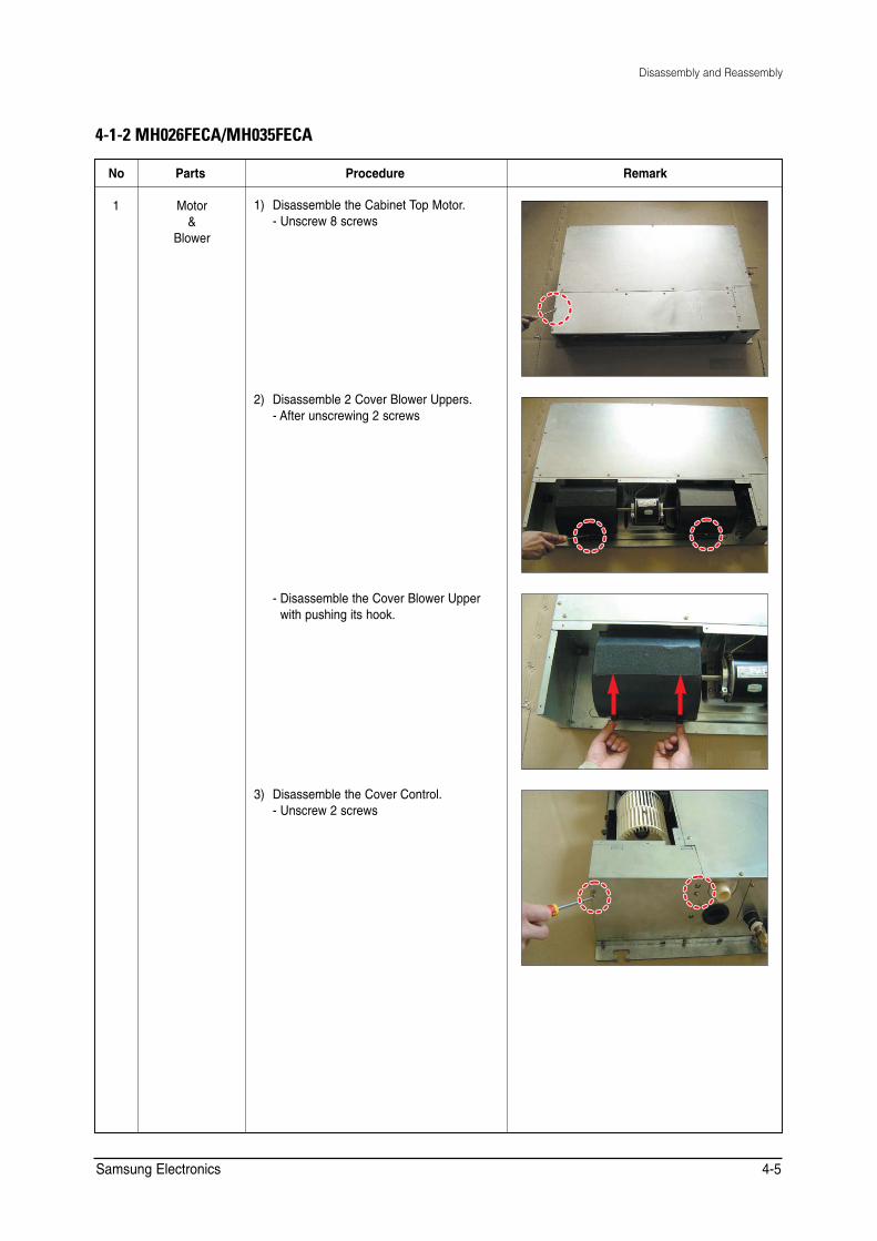
1) Disassemble the Cabinet Top Motor. - Unscrew 8 screws
2) Disassemble 2 Cover Blower Uppers. - After unscrewing 2 screws
- Disassemble the Cover Blower Upper with pushing its hook.
3) Disassemble the Cover Control. - Unscrew 2 screws
Samsung Electronics 4-5
Disassembly and Reassembly
No Parts Procedure Remark
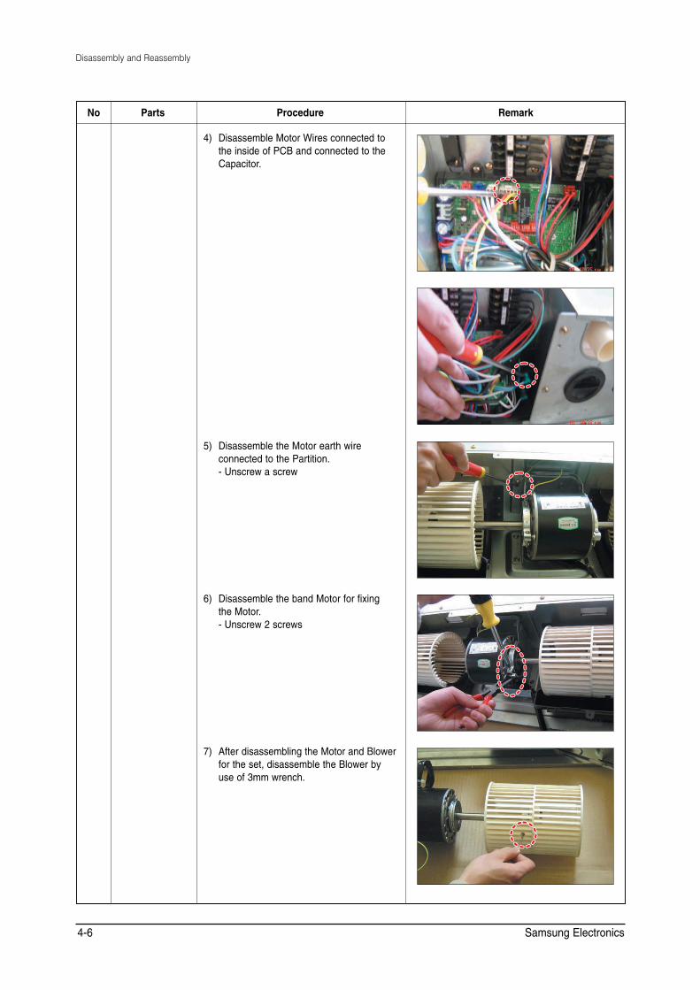
4) Disassemble Motor Wires connected to the inside of PCB and connected to the Capacitor.
5) Disassemble the Motor earth wire connected to the Partition. - Unscrew a screw
6) Disassemble the band Motor for fixing the Motor. - Unscrew 2 screws
7) After disassembling the Motor and Blower for the set, disassemble the Blower by use of 3mm wrench.
Samsung Electronics 4-6

Disassembly and Reassembly
No Parts Procedure Remark
2 Drain Pan 1) Disassemble the Cabinet Top Evap. - Unscrew 11 screws
2) Disassemble the Bracket Outlet Sub that fixes the Drain Pan equipped on the front of the set. - Unscrew 6 screws
3) Disassemble the Drain Cushion from the set.
Samsung Electronics 4-7
Disassembly and Reassembly
No Parts Procedure Remark
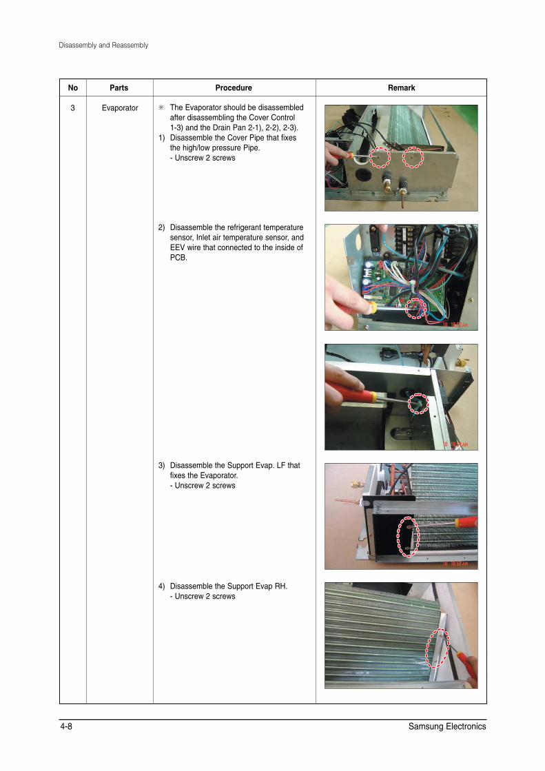
3 Evaporator ✳ The Evaporator should be disassembled after disassembling the Cover Control 1-3) and the Drain Pan 2-1), 2-2), 2-3).
1) Disassemble the Cover Pipe that fixes the high/low pressure Pipe. - Unscrew 2 screws
2) Disassemble the refrigerant temperature sensor, Inlet air temperature sensor, and EEV wire that connected to the inside of PCB.
3) Disassemble the Support Evap. LF that fixes the Evaporator. - Unscrew 2 screws
4) Disassemble the Support Evap RH. - Unscrew 2 screws
Samsung Electronics 4-8

Disassembly and Reassembly
No Parts Procedure Remark
5) Disassemble the Evaporator form the set.
4 Control In ✳ The Control In should be disassembled after disassembling the Cover Control 1-3).
1) Disassemble all Control Wires connected to the inside of PCB.
2) In case of disassembling the PCB separately, disassemble the PCB from the case with pushing the hook after unscrewing the screw. - Unscrew 1 screw
3) In case of disassembling the Capacitor separately, disassemble the Capacitor from the Case.
4) In case of disassembling the Case Control, disassemble the Case Control from the set after unscrewing the screw connected to the direction of Blower. - Disassemble if after disassembling the Cabinet Top Motor 1-1).
Samsung Electronics 4-9

Disassembly and Reassembly
No Parts Procedure Remark
5) In case of disassembling the Trans Power, unscrew the screw fixing on the Case. ✳ Disassemble if after disassembling the
case PCB 4-4).
5 Bracket Outlet 1) Disassemble the Bracket Outlet
assembled on the Cabinet. - Unscrew 10 screws
Samsung Electronics 4-10

Disassembly and Reassembly
4-1-3 MH052FECA
No Parts Procedure Remark
1 Filter 1) Pull out the Filter as picture 1 or picture 2.
2) If it is necessary, after disassembling 8 indicating screws, detach the Bracket Filter.
Samsung Electronics 4-11
Disassembly and Reassembly
No Parts Procedure Remark
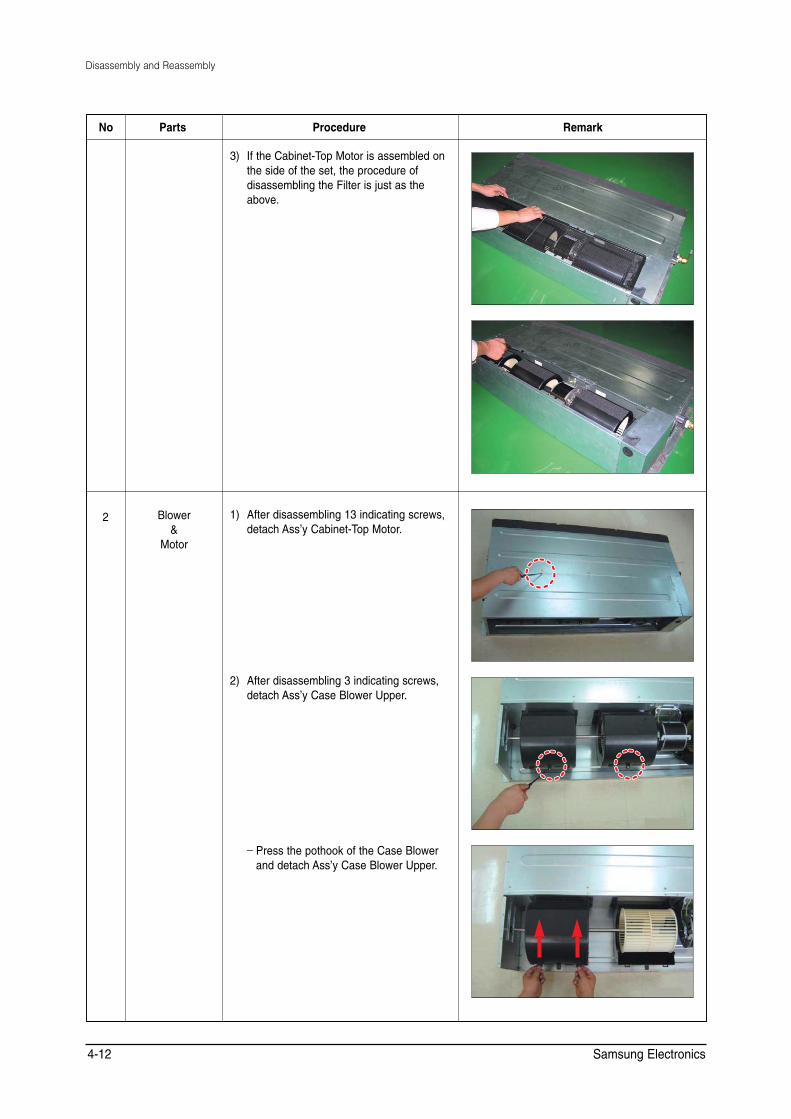
3) If the Cabinet-Top Motor is assembled on the side of the set, the procedure of disassembling the Filter is just as the above.
2 Blower &
Motor
1) After disassembling 13 indicating screws, detach Ass’y Cabinet-Top Motor.
2) After disassembling 3 indicating screws, detach Ass’y Case Blower Upper.
_ Press the pothook of the Case Blower and detach Ass’y Case Blower Upper.
Samsung Electronics 4-12
Disassembly and Reassembly
No Parts Procedure Remark
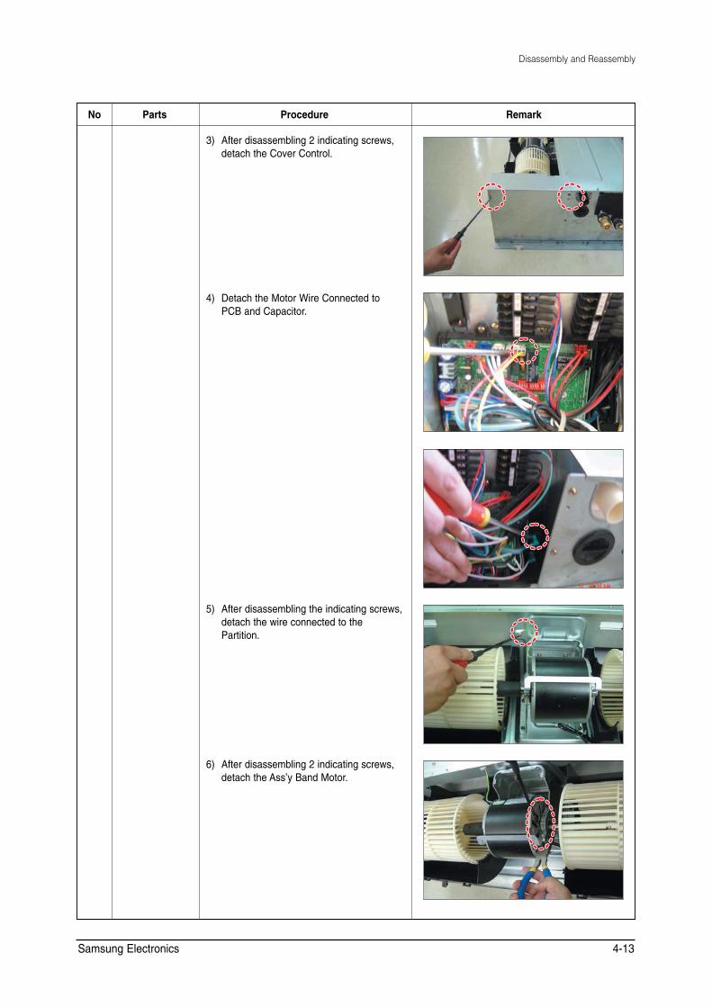
3) After disassembling 2 indicating screws, detach the Cover Control.
4) Detach the Motor Wire Connected to PCB and Capacitor.
5) After disassembling the indicating screws, detach the wire connected to the Partition.
6) After disassembling 2 indicating screws, detach the Ass’y Band Motor.
Samsung Electronics 4-13

Disassembly and Reassembly
No Parts Procedure Remark
7) After disassembling the Motor and Blowers, detach the Blowers from the axis of the Motor by 3mm inner hexagon spanner.
3 Drain Pan 1) After disassembling 15 indicating screws, detach Ass’y Cabinet-Top Evap.
2) After disassembling 6 indicating screws, detach the Bracket Outlet.
3) Detach the Drain Pan.
Samsung Electronics 4-14
Disassembly and Reassembly
No Parts Procedure Remark
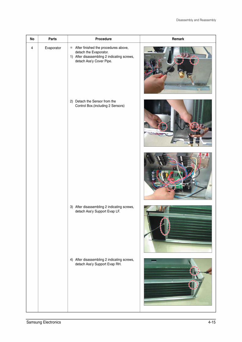
4 Evaporator ✳ After finished the procedures above, detach the Evaporator.
1) After disassembling 2 indicating screws, detach Ass'y Cover Pipe.
2) Detach the Sensor from the Control Box.(including 2 Sensors)
3) After disassembling 2 indicating screws, detach Ass'y Support Evap LF.
4) After disassembling 2 indicating screws, detach Ass'y Support Evap RH.
Samsung Electronics 4-15

Disassembly and Reassembly
No Parts Procedure Remark
5) Detach the Evaporator from the set.
5 Control In ✳ Detach the parts of Control In after disassembling the Cover Control.
1) Detach all the wires connected to the PCB.
2) If only the disassembly of PCB required, press the Pothook and detach the PCB from the set.
3) If only the disassembly of Capacitor is required, detach it from the set.
4) If only the disassembly of Case Control is required, detach it from the set after disassembling 2 indicating screws.
Samsung Electronics 4-16

Disassembly and Reassembly
No Parts Procedure Remark
5) Detach the Transformer after disassembling 2 indicating screws. ✳ Work is possible after disassembling
the Case PCB.
6 Ass'y Bracket Outlet
1) After disassembling 16 indicating screws, detach Ass'y Bracket Outlet.
Samsung Electronics 4-17
4-2 Outdoor Unit
4-2-1 MH050FXCA2A
No Parts Procedure Remark
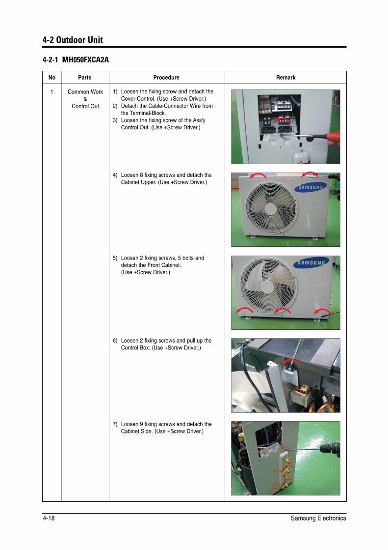
1 Common Work &
Control Out
1) Loosen the fixing screw and detach the Cover-Control. (Use +Screw Driver.)
2) Detach the Cable-Connector Wire from the Terminal-Block.
3) Loosen the fixing screw of the Ass'y Control Out. (Use +Screw Driver.)
4) Loosen 8 fixing screws and detach the Cabinet Upper. (Use +Screw Driver.)
5) Loosen 2 fixing screws, 5 bolts and detach the Front Cabinet. (Use +Screw Driver.)
6) Loosen 2 fixing screws and pull up the Control Box. (Use +Screw Driver.)
7) Loosen 9 fixing screws and detach the Cabinet Side. (Use +Screw Driver.)
Samsung Electronics 4-18
Disassembly and Reassembly
No Parts Procedure Remark
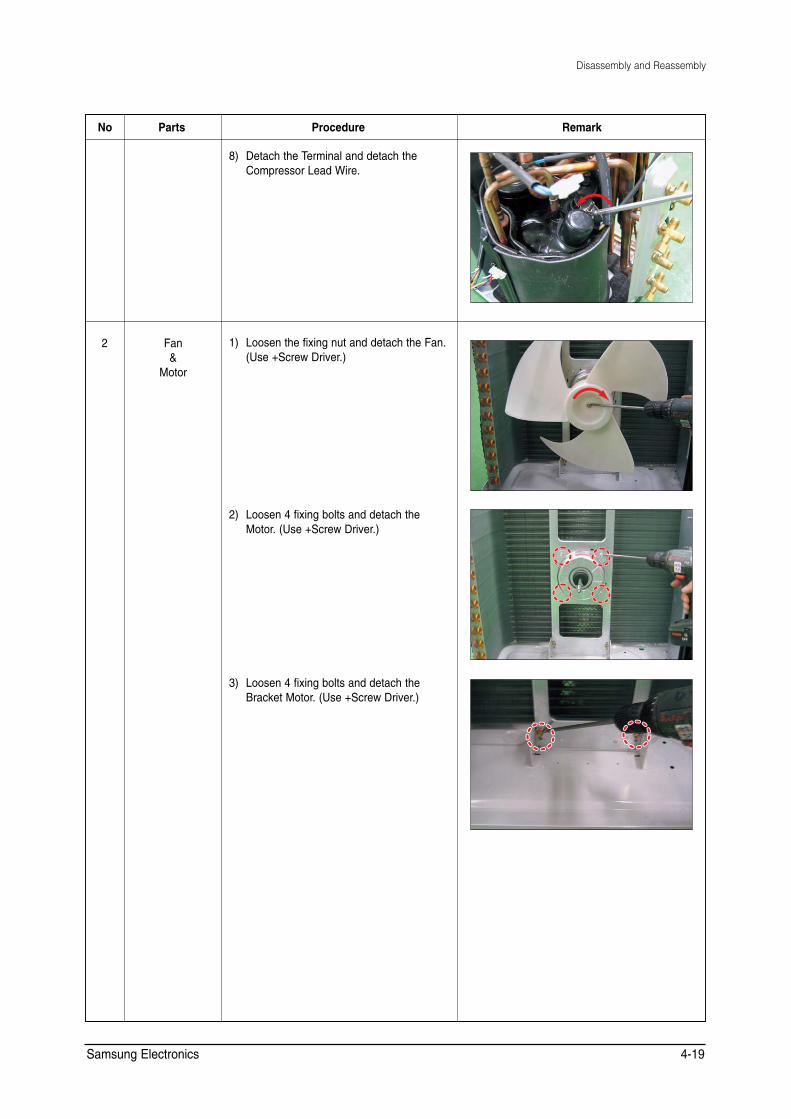
8) Detach the Terminal and detach the Compressor Lead Wire.
2 Fan &
Motor
1) Loosen the fixing nut and detach the Fan. (Use +Screw Driver.)
2) Loosen 4 fixing bolts and detach the Motor. (Use +Screw Driver.)
3) Loosen 4 fixing bolts and detach the Bracket Motor. (Use +Screw Driver.)
Samsung Electronics 4-19
Disassembly and Reassembly
No Parts Procedure Remark
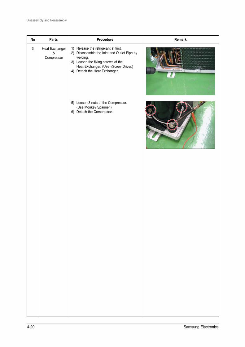
3 Heat Exchanger &
Compressor
1) Release the refrigerant at first. 2) Disassemble the Inlet and Outlet Pipe by
welding. 3) Loosen the fixing screws of the
Heat Exchanger. (Use +Screw Driver.) 4) Detach the Heat Exchanger.
5) Loosen 3 nuts of the Compressor. (Use Monkey Spanner.)
6) Detach the Compressor.
Samsung Electronics 4-20
Disassembly and Reassembly
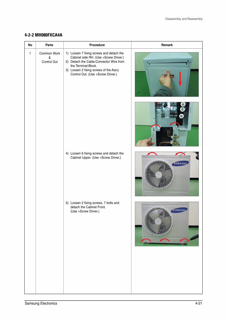
4-2-2 MH080FXCA4A
No Parts Procedure Remark
1 Common Work &
Control Out
1) Loosen 7 fixing screws and detach the Cabinet side RH. (Use +Screw Driver.)
2) Detach the Cable-Connector Wire from the Terminal-Block.
3) Loosen 2 fixing screws of the Ass'y Control Out. (Use +Screw Driver.)
4) Loosen 6 fixing screws and detach the Cabinet Upper. (Use +Screw Driver.)
5) Loosen 2 fixing screws, 7 bolts and detach the Cabinet Front. (Use +Screw Driver.)
Samsung Electronics 4-21
Disassembly and Reassembly
No Parts Procedure Remark
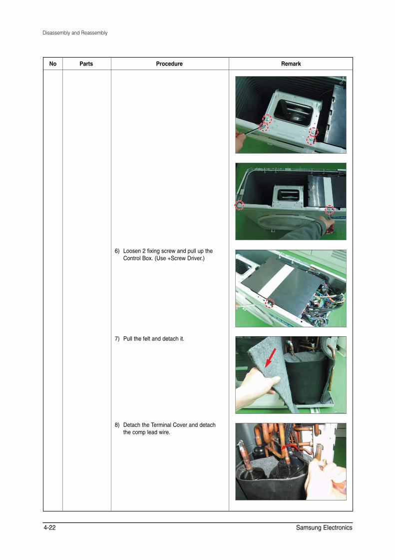
6) Loosen 2 fixing screw and pull up the Control Box. (Use +Screw Driver.)
7) Pull the felt and detach it.
8) Detach the Terminal Cover and detach the comp lead wire.
Samsung Electronics 4-22
Disassembly and Reassembly
No Parts Procedure Remark
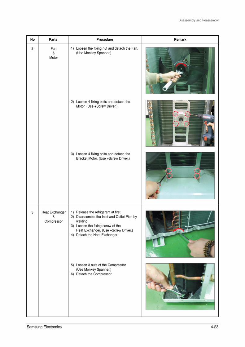
2 Fan &
Motor
1) Loosen the fixing nut and detach the Fan. (Use Monkey Spanner.)
2) Loosen 4 fixing bolts and detach the Motor. (Use +Screw Driver.)
3) Loosen 4 fixing bolts and detach the Bracket Motor. (Use +Screw Driver.)
3 Heat Exchanger &
Compressor
1) Release the refrigerant at first. 2) Disassemble the Inlet and Outlet Pipe by
welding. 3) Loosen the fixing screw of the
Heat Exchanger. (Use +Screw Driver.) 4) Detach the Heat Exchanger.
5) Loosen 3 nuts of the Compressor. (Use Monkey Spanner.)
6) Detach the Compressor.
Samsung Electronics 4-23
���"TLHK@A@�3EASO�=J@�-=NPO�)EOP
����&J@KKN�2JEP
������*%���#+ ��*%���#+ �
�
�
�
���
���
��� ���
���
���
� ��� �
����
���
���
��� � ��� ���
��� ���
� ��� ���
��� ���
���
��� �
���
��� 5COUWPI�'NGEVTQPKEU
([SORGHG�9LHZV�DQG�3DUWV�/LVW
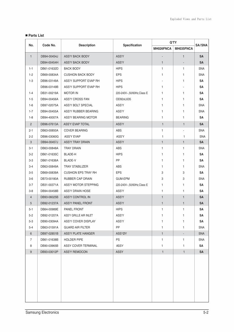
2CTVU�.KUV
0Q� %QFG�0Q� &GUETKRVKQP 5RGEKHKECVKQP 36;
5#�50# /*���(0%# /*���(0%#
�
���
���
���
���
���
���
���
���
�
���
���
�
���
���
���
���
���
���
���
���
�
�
���
���
���
���
�
�
�
�
&$��������,
&$��������*
&$��������&
&$��������#
&$��������#
&$��������$
&$��������#
&$��������#
&$��������#
&$��������#
&$��������#
&$��������$
&$��������#
&$��������)
&$��������,
&$��������#
&$��������%
&$��������#
&$��������#
&$��������#
&$��������#
&$��������#
&$��������$
&$��������$
&$��������#
&$��������'
&$��������#
&$��������#
&$��������#
&$��������$
&$��������$
&$��������$
&$��������2
#55; $#%-�$1&;
#55; $#%-�$1&;
$#%-�$1&;
%75*+10�$#%-�$1&;
#55; 5722146 '8#2 4*
#55; 5722146 '8#2 4*
/1614�+0
#55; %4155�(#0
#55; $1.6 52'%+#.
#55; 47$$'4�$'#4+0)
#55; $'#4+0)�/1614
#55; '8#2 616#.
%18'4�$'#4+0)
#55; '8#2
#55; 64#; &4#+0
64#; &4#+0
$.#&'�*
$.#&'�8
64#; 56#$+.+<'4
%75*+10�'25�64#; 4*
47$$'4�%#2 &4#+0
#55; /1614�56'22+0)
#55; &4#+0�*15'
#55; %10641. +0
#55; 2#0'. (4106
2#0'. (4106
#55; )4+..'�#+4�+0.'6
#55; %18'4�&+52.#;
)7#4&�#+4�(+.6'4
#55; 2.#6'�*#0)'4
*1.&'4�2+2'
#55;�%18'4�6'4/+0#.��������������������
#55; 4'/1%10
#55;
#55;
*+25
'25
*+25
*+25
�������8`������*\�%NCUU�'
1&��Z.���
#55;
#55;
$'#4+0)
#55;
#$5
#55;
#55;
#$5
*+25
22
#$5
'25
)7/�'2/
�������8`������*\�%NCUU�'
#55;
#55;
#55;
*+25
#55;
#55;
22
#55u«;
25
����#66<
#55;������
�
�
�
�
�
�
�
�
�
�
�
�
�
�
�
�
�
�
�
�
�
�
�
�
�
�
�
�
�
�
�
�
�
�
�
�
�
�
�
�
�
�
�
�
�
�
�
�
�
�
�
�
�
�
�
�
�
�
�
�
�
�
�
�
�
�
5#
5#
50#
50#
5#
5#
5#
5#
50#
50#
5#
5#
50#
50#
5#
50#
5#
5#
50#
5#
50#
5#
5#
5#
5#
5#
5#
5#
50#
50#
50#
5#
5#
5COUWPI�'NGEVTQPKEU ���
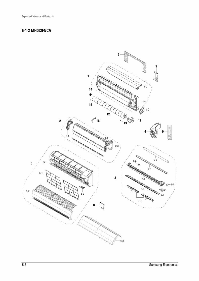
Exploded Views and Parts List
5-1-2 MH052FNCA
6
7
1
1-214
1-115
1012
2 16 1113
4 92-1
2-2
2-3
3-8
5 5-1 3-6
3-4
5-4
3 3-1
3-7
3-25-2
5-33-5
3-3
8
5-2
5-5-3 Samsung Electronics
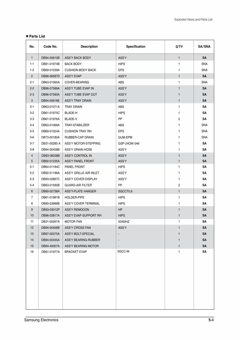
� � � �&YQMPEFE�7JFXT�BOE�1BSUT�-JTU
2CTVU�.KUV
0Q� %QFG�0Q� &GUETKRVKQP 5RGEKHKECVKQP 36; 5#�50#
�
���
���
�
���
���
���
�
���
���
���
���
���
���
���
���
�
�
���
���
���
���
�
�
�
�
��
��
��
��
��
��
��
&$��������$
&$��������$
&$��������#
&$��������&
&$��������#
&$��������#
&$��������#
&$��������'
&$��������#
&$��������%
&$��������#
&$��������#
&$��������#
&$��������#
&$���������#
&$��������$
&$��������$
&$��������#
&$��������%
&$��������#
&$��������%
&$��������$
&$��������#
&$��������$
&$��������$
&$��������2
&$��������#
&$��������#
&$��������$
&$��������#
&$��������#
&$��������#
&$��������# $4#%-'6�'8#2
#55ŏ; $#%-�$1&;
$#%-�$1&;
%75*+10�$1&; $#%-
#55ŏ; '8#2
%18'4�$'#4+0)
#55ŏ; 67$'�'8#2 +0
#55ŏ; 67$'�'8#2 176
#55ŏ; 64#; &4#+0
64#; &4#+0
$.#&'�*
$.#&'�8
64#;�56#$+.+<'4
%75*+10�64#; 4*
47$$'4�%#2 &4#+0
#55ŏ; /1614�56'22+0)
#55ŏ; &4#+0�*15'
#55ŏ; %10641. +0
#55ŏ; 2#0'. (4106
2#0'. (4106
#55ŏ; )4+..'�#+4�+0.'6
#55ŏ; %18'4�&+52.#;
)7#4&�#+4�(+.6'4
#55ŏ;�2.#6'�*#0)'4
*1.&'4�2+2'
#55ŏ;�%18'4�6'4/+0#.
#55ŏ; 4'/1%10
#55ŏ; '8#2�5722146 4*
/1614�(#0
#55ŏ; %4155�(#0
#55ŏ; $1.6�52'%+#.
#55ŏ; $'#4+0)�47$$'4
#55ŏ; $'#4+0)�/1614
#55ŏ;
*+25
'25
#55ŏ;
#$5
#55ŏ;
#55ŏ;
#55ŏ;
#$5
*+25
22
#$5
'25
)7/�'2/
)52���19����
#55ŏ;
#55ŏ;
#55ŏ;
*+25
#55ŏ;
#55ŏ;
22
5)%%6���
*+25
*+25
*2
*+25
�����*<
#55ŏ;
�
�
�
5)%%�/
�
�
�
�
�
�
�
�
�
�
�
�
�
�
�
�
�
�
�
�
�
�
�
�
�
�
�
�
�
�
�
�
�
5#
50#
50#
5#
50#
5#
5#
5#
5#
5#
5#
50#
50#
50#
5#
5#
5#
5#
5#
5#
5#
5#
5#
5#
5#
5#
5#
5#
5#
5#
5#
5#
5#
5COUWPI�'NGEVTQPKEU �����
Exploded Views and Parts List
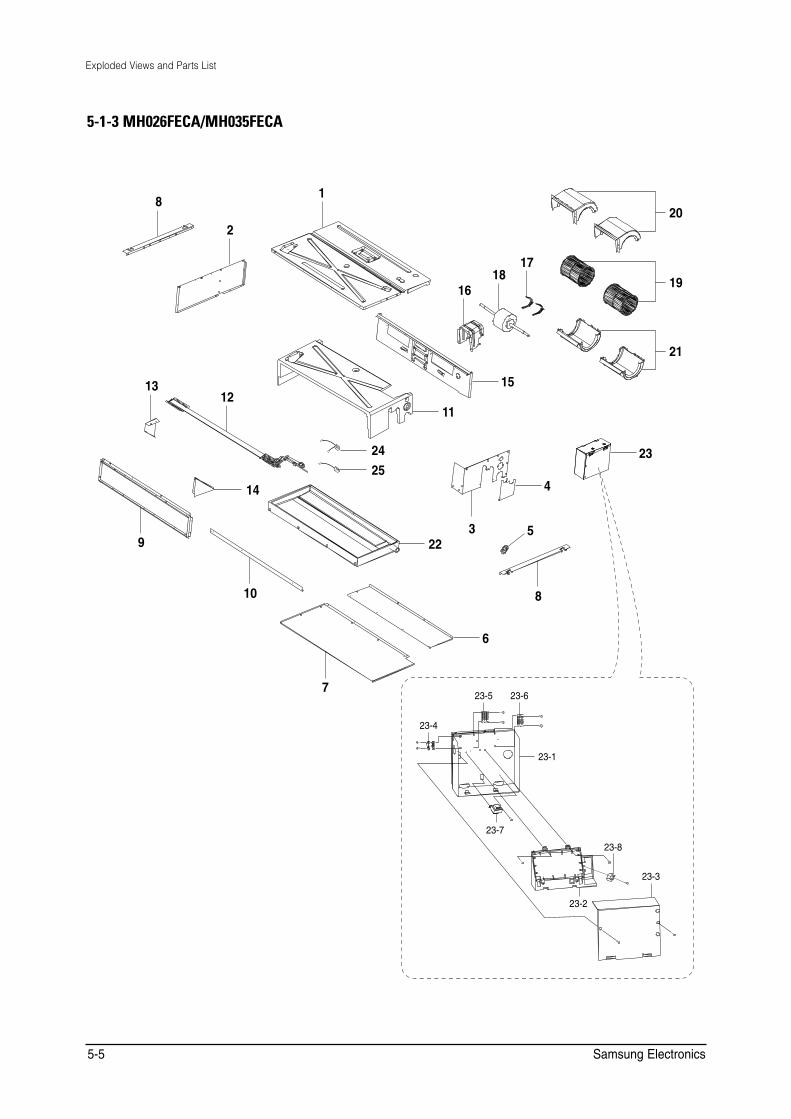
5-1-3 MH026FECA/MH035FECA
20
19
21
23
8
13
9
12
14
2
16 18
17
1
6
15
11
24 25
4
5 22
10
3
8
7
23-4
23-7
23-5 23-6
23-3
23-8
23-1
23-2
Samsung Electronics 5-5
Exploded Views and Parts List
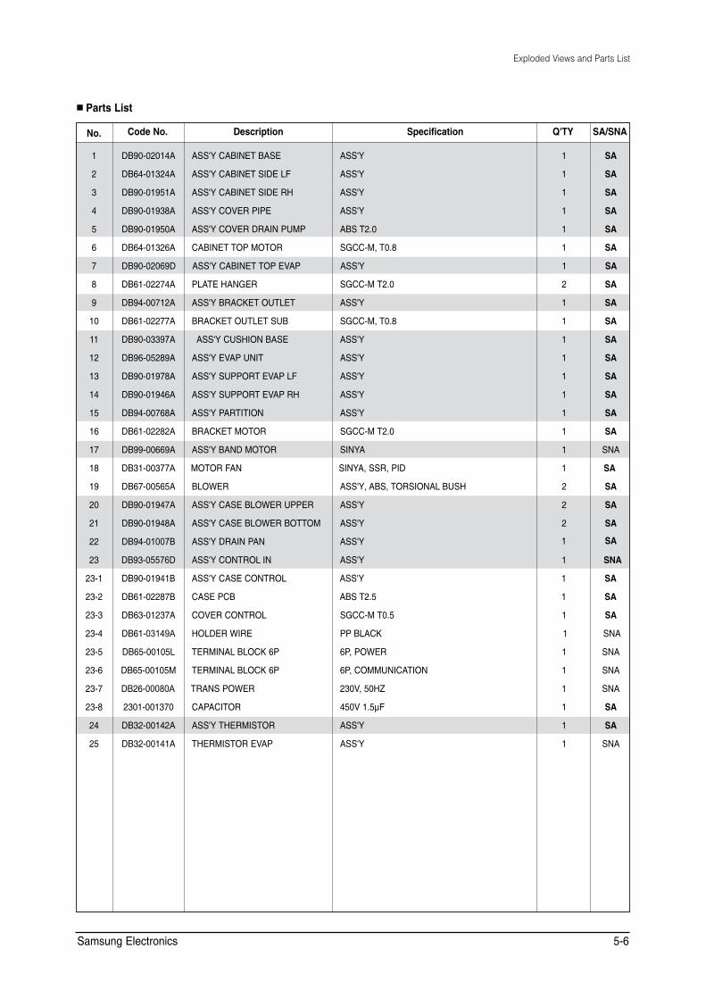
■ Parts List
0Q� %QFG�0Q� &GUETKRVKQP 5RGEKHKECVKQP 36; 5#�50#
�
�
�
�
�
�
�
�
�
��
��
��
��
��
��
��
��
��
��
��
��
��
��
����
����
����
����
����
����
����
����
��
��
&$��������#
&$��������#
&$��������#
&$��������#
&$��������#
&$��������#
&$��������'
&$��������#
&$��������#
&$��������#
&$��������#
&$��������#
&$��������#
&$��������#
&$��������#
&$��������#
&$��������#
&$��������$
&$��������#
&$��������#
&$��������#
&$��������%
&$��������'
&$��������%
&$��������%
&$��������#
&$��������$
&$��������.
&$��������/
&$��������$
�����������
&$��������#
&$��������#
#55; %#$+0'6 $#5'
#55; %#$+0'6 5+&'�.(
#55; %#$+0'6 5+&'�4*
#55; %18'4�2+2'
#55; %18'4�&4#+0�27/2
%#$+0'6 612 /1614
#55; %#$+0'6 612 '8#2
2.#6'�*#0)'4
#55; $4#%-'6 176.'6
$4#%-'6 176.'6 57$
#55; %75*+10�$#5'
#55; '8#2 70+6
#55; 5722146 '8#2 .(
#55; 5722146 '8#2 4*
#55; 2#46+6+10
$4#%-'6 /1614
#55; $#0&�/1614
/1614�(#0
$.19'4
#55; %#5'�$.19'4�722'4
#55; %#5'�$.19'4�$1661/
#55; &4#+0�2#0
#55; %10641. +0
#55; %#5'�%10641.
%#5'�2%$
%18'4�%10641.
*1.&'4�9+4'
6'4/+0#. $.1%-��2
6'4/+0#. $.1%-��2
64#05�219'4
%#2#%+614
#55; 6*'4/+5614
6*'4/+5614�'8#2
#55;
#55;
#55;
#55;
#$5�6���
5)%%�/��6���
#55;
5)%%�/�6���
#55;
5)%%�/��6���
#55;
#55;
#55;
#55;
#55;
5)%%�/�6���
5+0;#
5+0;#��554��2+&
#55;��#$5��6145+10#. $75*
#55;
#55;
#55;
#55;
#55;
#$5�6���
5)%%�/�6���
22 $.#%-
�2��219'4
�2��%1//70+%#6+10
���8����*<
���8����z(
#55;
#55;
�
�
�
�
�
�
�
�
�
�
�
�
�
�
�
�
�
�
�
�
�
�
�
�
�
�
�
�
�
�
�
�
�
5#
5#
5#
5#
5#
5#
5#
5#
5#
5#
5#
5#
5#
5#
5#
5#
50#
5#
5#
5#
5#
5#
50#
5#
5#
5#
50#
50#
50#
50#
5#
5#
50#
Samsung Electronics 5-6
Exploded Views and Parts List
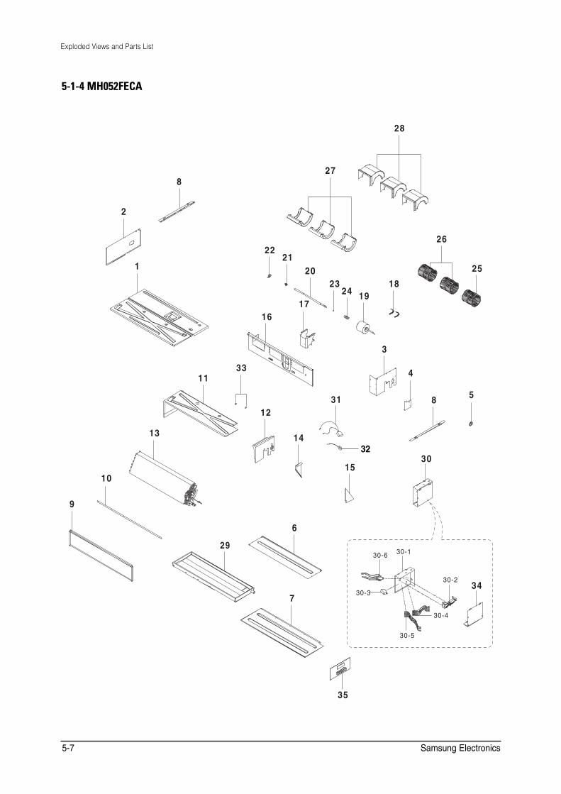
5-1-4 MH052FECA
28
278
2
2622
211 20 25
23 1824 19
1716
3
33 411
531 812
13 1432
3015
10
9
6
2930-130-6
30-234
30-37
30-4
30-5
35
5-7 Samsung Electronics

Exploded Views and Parts List
■ Parts List
0Q� %QFG�0Q� &GUETKRVKQP 5RGEKHKECVKQP 36; 5#�50#
�
�
�
�
�
�
�
�
�
��
��
��
��
��
��
��
��
��
��
��
��
��
��
��
��
��
��
��
��
��
����
����
����
����
����
����
��
��
��
��
��
&$��������#
&$��������$
&$��������#
&$��������#
&$��������#
&$��������#
&$��������%
&$��������#
&$��������#
&$��������#
&$��������#
&$��������#
&$��������$
&$��������#
&$��������#
&$��������#
&$��������#
&$��������#
&$��������&
&$��������#
&$��������#
&$��������#
&$��������#
&$��������#
&$��������#
&$��������#
&$��������#
&$��������#
&$��������#
&$��������&
&$��������%
&$��������%
�����������
&$��������.
&$��������/
&$��������)
&$��������#
&$��������#
&$��������#
&$��������#
&$��������&
#55; %#$+�$#5'
%#$+�5+&'�.(
#55; %#$+�5+&'�4*
#55; %18'4�2+2'
#55; %18'4�&4#+0�27/2
%#$+��612 /1614
#55; %#$+�612 '8#2
2.#6'4�*#0)'4
#55; $4#%-'6 176.'6
$4#%-'6 176.'6 57$
#55; %75*+10�$#5'�#
#55; %75*+10�$#5'�$�
#55; '8#2 70+6
#55; 5722146 '8#2 .(
#55; 5722146 '8#2 4*
#55; 2#46+6+10
$4#%-'6 /1614
#55; $#0&�/1614
/1614
/1614�5*#(6
/1.&�$'#4+0)
%#2 $'#4+0)
47$$'4�5*#(6
%172.'4
$.19'4�#
$.19'4�$
#55; %#5'�$.19'4�722'4
#55; %#5'�$.19'4�$1661/
#55; &4#+0�
#55 ; %10641. +0�
#55; %#5'�%10641.
%#5'�2%$
%#2#%+614
6'4/+0#. $.1%-��2
6'4/+0#. $.1%-��2
64#05�219'4
#55; 6*'4/+5614�������
6*'4/+5614�'8#2
%.+2 $475*
#55; %18'4�%10641.
#55; 2%$
#55;�5)%%�/�6������
5)%%�/�6����
#55;�5)%%�/�6�����
#55;�5)%%�/�6���
#55;
5)%%�/�6�������
#55;�5)%%�/�6�����
5)%%�/�6���
#55;�5)%%�/�6���
5)%%�/�6����
#55;�'25����
#55;�'25���
#55;
#55;�5)%%�/�6���
#55;�5)%%�/�6����
#55;�5)%%�/�6���
5)%%�/�6���
5+0;#�#55;
5+0;#���*<�;5-��������2)
5+0;#
#55;
5)%%�/�6���
%4�8�
#55;
#55;�#$5
#55;�#$5
#55; #$5
#55; #$5
#55;
#55;
#55;
#$5�8��6�����������
���8��7
�2�219'4
�2�%1//70+%#6+10
��*<
#55;
���OO
0;.10���$.#%-
#55;
#55;
�
�
�
�
�
�
�
�
�
�
�
�
�
�
�
�
�
�
�
�
�
�
�
�
�
�
�
�
�
�
�
�
�
�
�
�
�
�
�
�
�
5#
5#
5#
5#
5#
5#
5#
5#
5#
5#
5#
5#
5#
5#
5#
5#
5#
5#
5#
5#
5#
5#
5#
5#
5#
5#
5#
5#
5#
5#
5#
5#
5#
5#
5#
5#
5#
5#
5#
5#
5#
Samsung Electronics 5-8
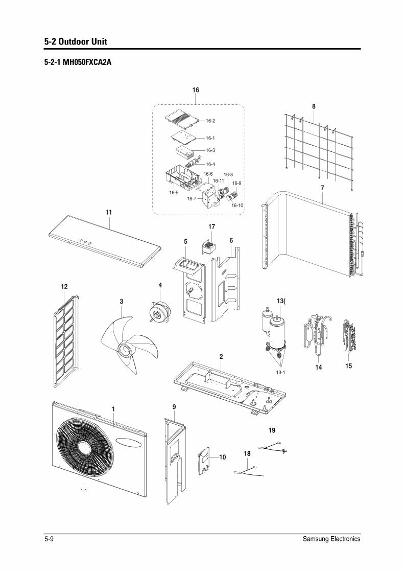
5-2 Outdoor Unit
5-2-1 MH050FXCA2A
��
8
����
����
����
����
���� ���� ����� ����
7 ����
���� �����
11
17
5 6
12 4
3 ��
2 15��
����
1 9
19
1810
1-1
5-9 Samsung Electronics
Exploded Views and Parts List
2CTVU�.KUV
0Q� %QFG�0Q� &GUETKRVKQP 5RGEKHKECVKQP 36;
5#�50# /*���(:%#�#
�
���
�
�
�
�
�
�
�
�
��
��
��
��
����
��
��
��
����
����
����
����
����
����
����
����
����
�����
�����
��
��
��
&$��������)
&$��������%
&$��������%
&$��������#
&$��������#
&$��������#
&$��������#
&$��������
&$��������$
&$��������%
&$��������#
&$��������#
&$��������#
)�6���(7#'9
&$��������#
&$��������#
&$��������$
&$��������&
&$��������&
&$��������%
&$��������$
&$��������$
&$��������%
&$��������#
&$��������$
&$��������&
&$��������(
&$��������#
&$��������#
&$��������#
&$��������$
&$��������#
#55; %#$+0'6 (4106
)7#4&�(#0
#55; $#5'�176
(#0�2412'..'4
/1614�(#0
$4#%-'6 /1614
#55; 2#46+6+10
#55; %10&'05'4
5%4''0�%10&�$#4
#55; %#$+0'6 5+&'
#55; %18'4�%10641.
#55; %#$+0'6 72
#55; %#$+0'6 .(
416#4; %1/24'5514
)41//'6�+51.#614
#55; 8#.8'���9#;
#55; 8#.8'
#55; %10641. 176
#55; 2%$�/#+0
%#5'�%10641.�%18'4
*'#6 5+0-
#55; 2%$�'/+
%#5'�%10641.�$#5'
2.#6'�%10641. 176 722'4
2.#6'�%10641. 176 /#+0
6'4/+0#. $.1%-
6'4/+0#. $.1%-
#55;�6'4/+0#. $.1%-
#55; 2%$�&+52.#;
�4'#%614
6*'4/+5614�%10&'05'4
6*'4/+5614�
#55;
22�5%������4
#55;
22
5)%%�/
#55;
#55;
#55;
*5945%������6�
#55;
#55;
#55;
5'%%�2
$.&%�2'4/#0'06 /#)0'6+% /1614
04
#55;
#55;
#55;
#55;
#55;
#$5
#55;
#.
5)%%�/
#$5
$.-
$.-
#55;
#55;
�/*v�������v�8
���#6����%6$
���#6����%6$
�
�
�
�
�
�
�
�
�
�
�
�
�
�
�
�
�
�
�
�
�
�
�
�
�
�
�
�
�
�
�
�
5#
5#
50#
5#
5#
5#
50#
5#
5#
5#
5#
5#
5#
5#
50#
5#
5#
5#
5#
5#
50#
50#
5#
50#
50#
5%
5%
5%
5#
5#
5#
5#
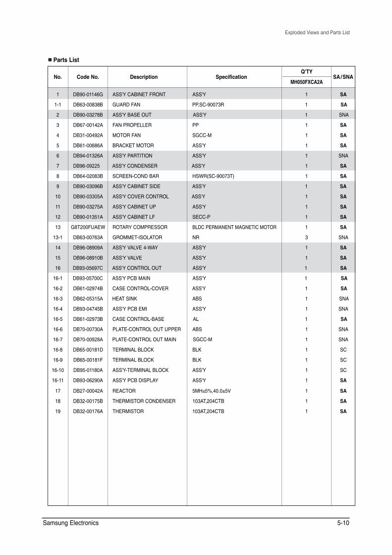
Samsung Electronics 5-10
Exploded Views and Parts List
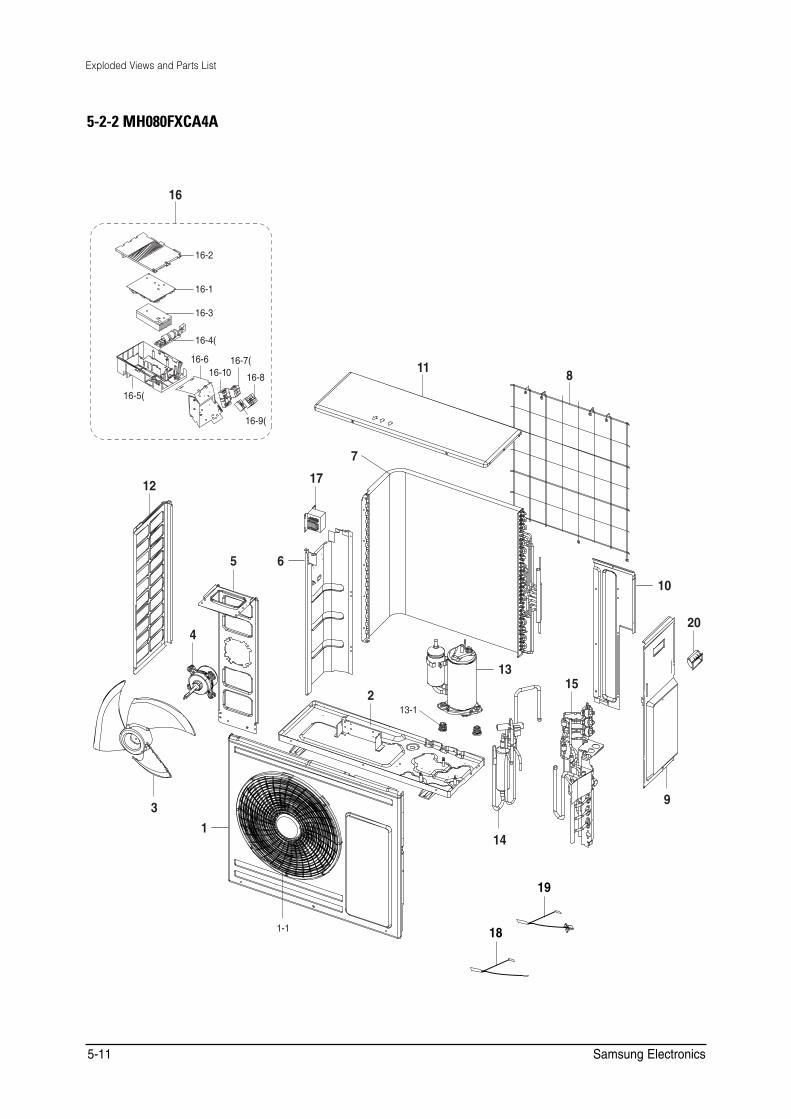
5-2-2 MH080FXCA4A
��
����
����
����
����
���� ����11����� ���� 8
����
����
7
1712
5 6
10
204
1315
213-1
93
114
19
1-1 18
5-11 Samsung Electronics
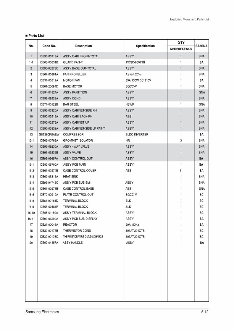
Exploded Views and Parts List
■ Parts List
0Q� %QFG�0Q� &GUETKRVKQP 5RGEKHKECVKQP 36;
5#�50# /*���(:'#�$
�
���
�
�
�
�
�
�
�
�
��
��
��
��
����
��
��
��
����
����
����
����
����
����
����
����
�����
�����
��
��
��
��
&$��������#
&$��������%
&$��������%
&$��������#
&$��������#
&$��������&
&$��������$
&$��������#
&$��������%
&$��������#
&$��������#
&$��������#
&$��������#
)�6���(7#'9
&$��������#
&$��������#
&$��������$
&$��������$
&$��������$
&$��������%
&$��������#
&$��������&
&$��������%
&$��������#
&$��������&
&$��������(
&$��������#
&$��������#
&$��������#
&$��������$
&$��������%
&$��������#����
#55ŏ; %#$+�(4106�616#.
)7#4&�(#0�2
#55ŏ; $#5'�176�616#.
(#0�241('..'4
/1614�(#0
$#5'�/1614
#55ŏ; 2#46+6+10
#55ŏ; %10&
$#4�56''.
#55ŏ; %#$+0'6�5+&'�4*
#55ŏ; %#$+�$#%-�4*
#55ŏ; %#$+0'6 72
#55ŏ; %#$+0'6�5+&'�.(�2#+06
%1/24'5514
)41//'6 +51.#614
#55ŏ; �9#; 8#.8'
#55ŏ; 8#.8'
#55ŏ; %10641. 176
#55ŏ; 2%$�/#+0
%#5'�%10641. %18'4
*'#6 5+0-
#55ŏ; 2%$�57$�'/+
%#5'�%10641. $#5'
2.#6'�%10641. 176
6'4/+0#. $.1%-
6'4/+0#. $.1%-
#55ŏ;�6'4/+0#. $.1%-
#55ŏ; 2%$�57$�&+52.#;
4'#%614
6*'4/+5614�%10&
6*'4/+5614�9+4'�176�&+5%*#4)'
��$66<�+$1'/(
#55ŏ;
22�5%������4
#55ŏ;
#5�)(����
��#����9�&%����8
5)%%�/
#55ŏ;
#55ŏ;
*594
#55ŏ;
#$5
#55ŏ;
#55ŏ;
$.&%�+08'46'4
04
#55ŏ;
#55ŏ;
#55ŏ;
#55ŏ;
#$5
#55ŏ;
#$5
5)%%�/
$.-
$.-
#55ŏ;
#55ŏ;
��#����*\
���#6����%6$
���#6����%6$
#66<
�
�
�
�
�
�
�
�
�
�
�
�
�
�
�
�
�
�
�
�
�
�
�
�
�
�
�
�
�
�
�
�
50#
5#
50#
50#
5#
50#
50#
50#
50#
50#
50#
50#
50#
5#
50#
50#
50#
5#
5#
5#
50#
50#
50#
5%
5%
5%
5%
5#
5#
5%
5%
5#
Samsung Electronics 5-12
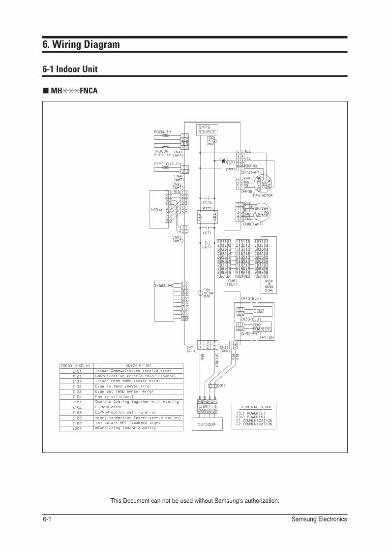
6. Wiring Diagram
6-1 Indoor Unit
■ MH✳✳✳FNCA
This Document can not be used without Samsung's authorization.
Samsung Electronics 6-1
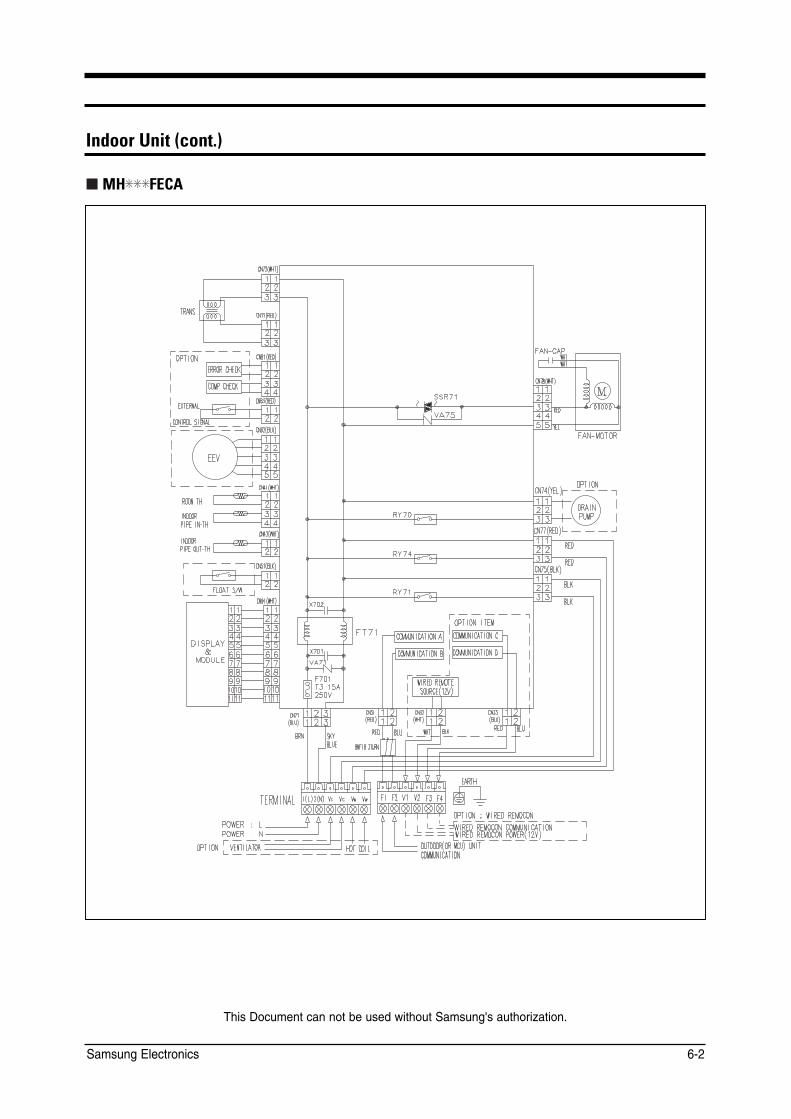
&J@KKN�2JEP�Ġ?KJP�
*% #" A
This Document can not be used without Samsung's authorization.
Samsung Electronics 6-2

6-2 Outdoor Unit
■ MH050FXCA2A
This Document can not be used without Samsung's authorization.
6-3 Samsung Electronics
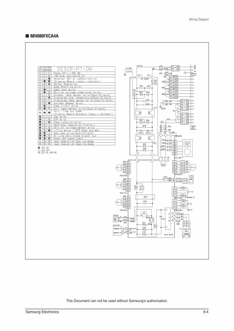
Wiring Diagram
■ MH080FXCA4A
This Document can not be used without Samsung's authorization.
Samsung Electronics 6-4

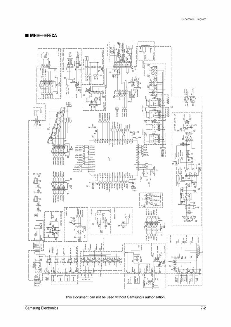
7. Schematic Diagram
7-1 Indoor Unit
■ MH✳✳✳FNCA
This Document can not be used without Samsung's authorization.
7-1 Samsung Electronics
Schematic Diagram
■ MH✳✳✳FECA
This Document can not be used without Samsung's authorization.
Samsung Electronics 7-2
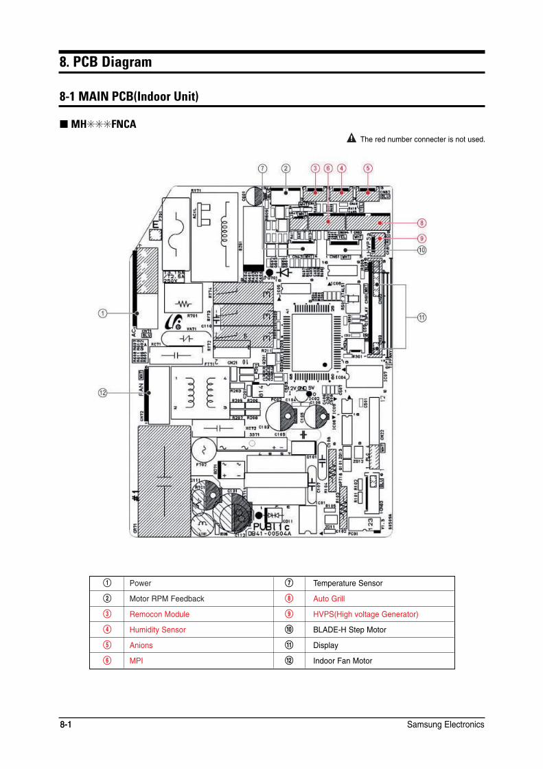
8. PCB Diagram
8-1 MAIN PCB(Indoor Unit)
■ MH✳✳✳FNCA The red number connecter is not used.
! Power & Temperature Sensor
@ Motor RPM Feedback * Auto Grill
# Remocon Module ( HVPS(High voltage Generator)
$ Humidity Sensor ) BLADE-H Step Motor
% Anions 1 Display
^ MPI 2 Indoor Fan Motor
Samsung Electronics 8-1 8-1
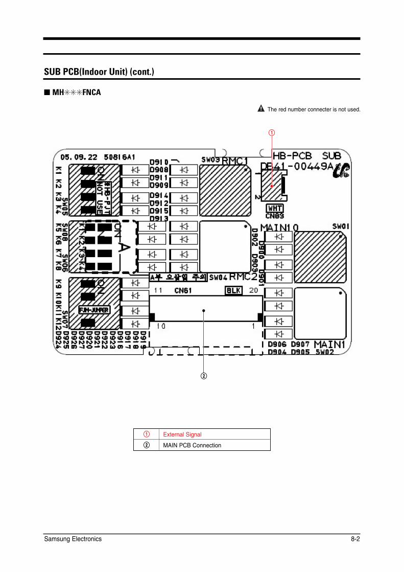
02��- �Ġ&J@KKN�2JEP�Ġ?KJP�
■ MH✳✳✳FNCA
The red number connecter is not used.
!
@
! External Signal
@ MAIN PCB Connection
Samsung Electronics 8-2
PCB Diagram
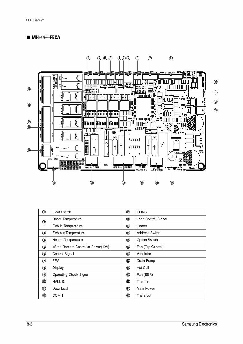
■ MH✳✳✳FECA
)
1
2
3
5
8
9
7
6
! @ 4 (# $ % ^ & *
0 “ ‘ + = Q
! Float Switch 3 COM 2
@ Room Temperature 4 Load Control Signal
EVA in Temperature 5 Heater
# EVA out Temperature 6 Address Switch
$ Heater Temperature 7 Option Switch
% Wired Remote Controller Power(12V) 8 Fan (Tap Control)
^ Control Signal 9 Ventilator
& EEV 0 Drain Pump
* Display “ Hot Coil
( Operating Check Signal ‘ Fan (SSR)
) HALL IC + Trans In
1 Download = Main Power
2 COM 1 Q Trans out
Samsung Electronics 8-3
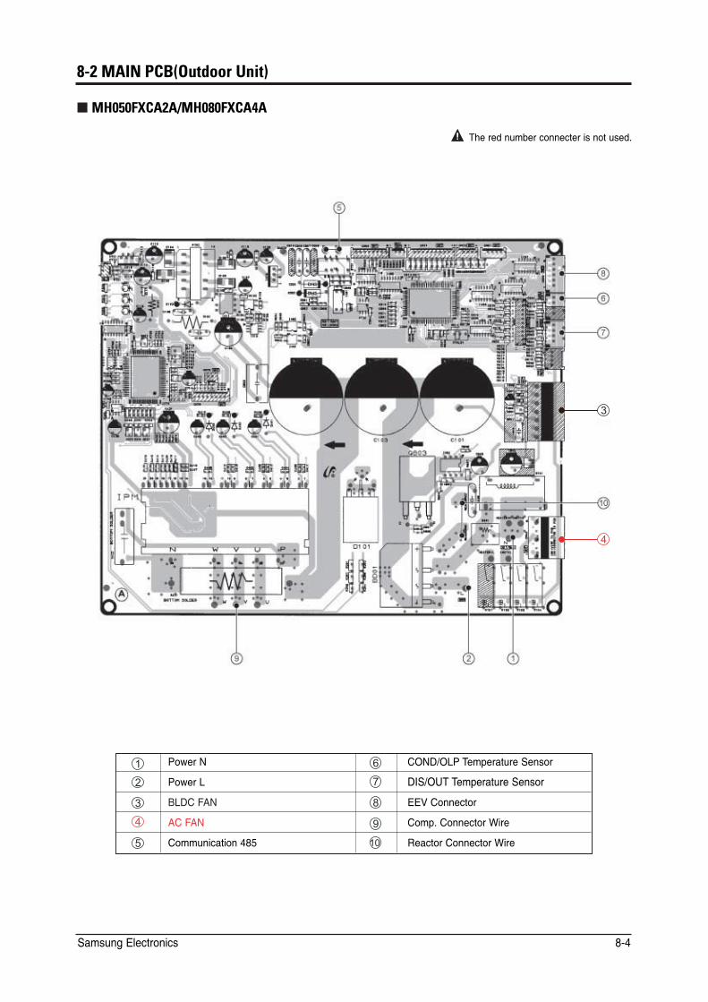
����*�&+ - �Ġ,QP@KKN�2JEP
*%���#5 ����*%���#5 ���
6JG�TGF�PWODGT�EQPPGEVGT�KU�PQV�WUGF�
�
�
� 2QYGT�0 � %10&�1.2 6GORGTCVWTG�5GPUQT
� 2QYGT�. � &+5�176 6GORGTCVWTG�5GPUQT
� $.&%�(#0 � ''8�%QPPGEVQT
� #%�(#0 � %QOR��%QPPGEVQT�9KTG
� %QOOWPKECVKQP���� �� 4GCEVQT�%QPPGEVQT�9KTG
5COUWPI�'NGEVTQPKEU ���
9. Troubleshooting
9-1 Items to be checked first
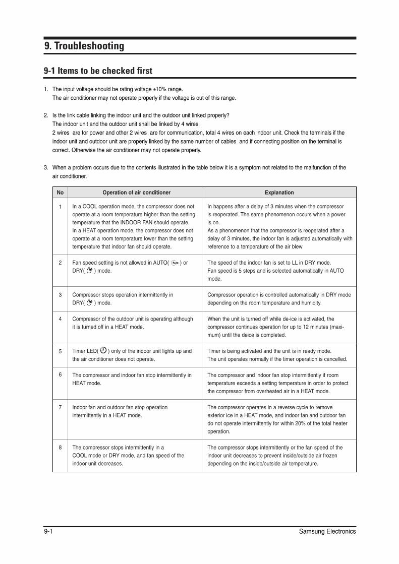
1. The input voltage should be rating voltage ±10% range. The air conditioner may not operate properly if the voltage is out of this range.
2. Is the link cable linking the indoor unit and the outdoor unit linked properly? The indoor unit and the outdoor unit shall be linked by 4 wires. 2 wires are for power and other 2 wires are for communication, total 4 wires on each indoor unit. Check the terminals if the indoor unit and outdoor unit are properly linked by the same number of cables and if connecting position on the terminal is correct. Otherwise the air conditioner may not operate properly.
3. When a problem occurs due to the contents illustrated in the table below it is a symptom not related to the malfunction of the air conditioner.
No Operation of air conditioner Explanation
1 In a COOL operation mode, the compressor does not operate at a room temperature higher than the setting temperature that the INDOOR FAN should operate. In a HEAT operation mode, the compressor does not operate at a room temperature lower than the setting temperature that indoor fan should operate.
In happens after a delay of 3 minutes when the compressor is reoperated. The same phenomenon occurs when a power is on. As a phenomenon that the compressor is reoperated after a delay of 3 minutes, the indoor fan is adjusted automatically with reference to a temperature of the air blew
2 Fan speed setting is not allowed in AUTO( ) or DRY( ) mode.
The speed of the indoor fan is set to LL in DRY mode. Fan speed is 5 steps and is selected automatically in AUTO mode.
3 Compressor stops operation intermittently in DRY( ) mode.
Compressor operation is controlled automatically in DRY mode depending on the room temperature and humidity.
4 Compressor of the outdoor unit is operating although it is turned off in a HEAT mode.
When the unit is turned off while de-ice is activated, the compressor continues operation for up to 12 minutes (maximum) until the deice is completed.
5 Timer LED( ) only of the indoor unit lights up and the air conditioner does not operate.
Timer is being activated and the unit is in ready mode. The unit operates normally if the timer operation is cancelled.
6 The compressor and indoor fan stop intermittently in HEAT mode.
The compressor and indoor fan stop intermittently if room temperature exceeds a setting temperature in order to protect the compressor from overheated air in a HEAT mode.
7 Indoor fan and outdoor fan stop operation intermittently in a HEAT mode.
The compressor operates in a reverse cycle to remove exterior ice in a HEAT mode, and indoor fan and outdoor fan do not operate intermittently for within 20% of the total heater operation.
8 The compressor stops intermittently in a COOL mode or DRY mode, and fan speed of the indoor unit decreases.
The compressor stops intermittently or the fan speed of the indoor unit decreases to prevent inside/outside air frozen depending on the inside/outside air temperature.
Samsung Electronics 9-1
1.1.1.1.1.1.1.1.1.1.1.1.
2.2. ■
2. ■
9-2 Checking and Testing operations
To complete the installation, perform the following checks and tests to ensure that the air conditioner is operating correctly.
1. Review all the following elements in the installation: • Installation site strength • Piping connection tightness not to leak any gas • Connection wiring • Heat-resistant insulation of the piping • Drainage • Earthing wire connection • Setting number of the indoor unit installed (Outdoor unit SW) • Setting SW02 for addressing mode (AUTO or MANUAL) • Address number on each indoor unit (Manual addressing mode) • Correct operation for pipe checking connection (follow the step below) • If the auto addressing, refer to next page. • If the manual addressing, please do cool mode try-run or heat mode try-run.(refer to below)
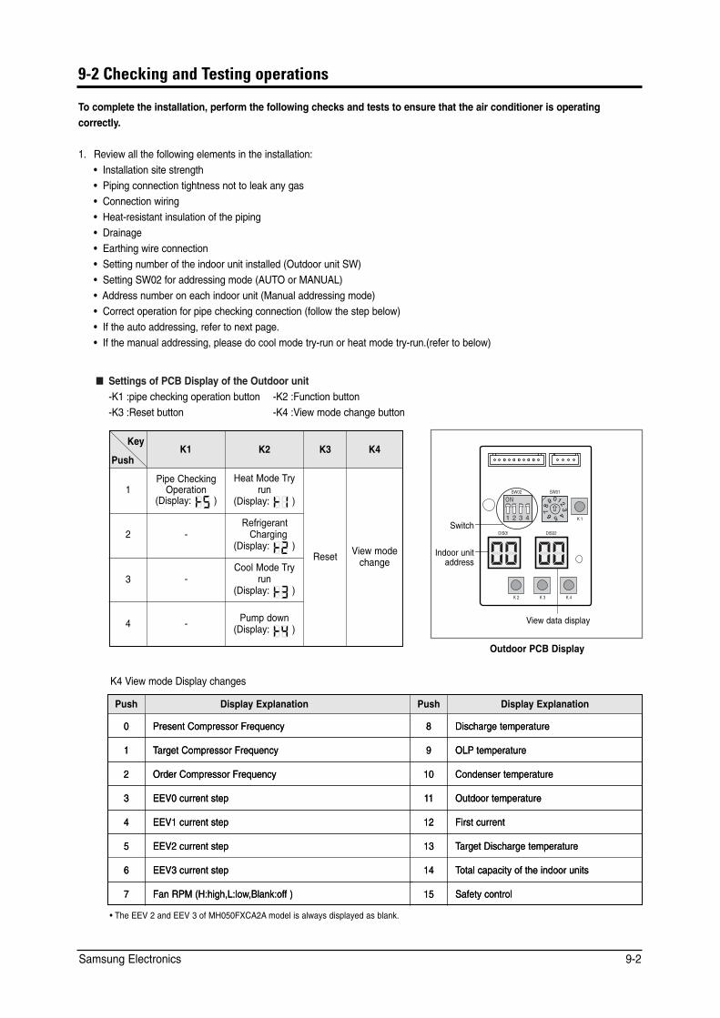
■ Settings of PCB Display of the Outdoor unit -K1 :pipe checking operation button -K2 :Function button -K3 :Reset button -K4 :View mode change button
Push
Key K1 K2 K3 K4
Pipe Checking Heat Mode Try 1 Operation run
(Display: ) (Display: )
Reset View mode change
2 -Refrigerant
Charging (Display: )
Cool Mode Try 3 - run
(Display: )
4 - Pump down (Display: )
K 1
K 2 K 3
DIS01
SW02 SW01
K 4
DIS02
Indoor unit address
View data display
Switch
Outdoor PCB Display
K4 View mode Display changes
Push Display Explanation Push Display Explanation
00 Present Compressor FrequencyPresent Compressor Frequency 88 Discharge temperatureDischarge temperature
11 TTarget Compressor Frequencyarget Compressor Frequency 99 OLPOLP temperaturetemperature
22 Order Compressor FrequencyOrder Compressor Frequency 1010 Condenser temperatureCondenser temperature
33 EEV0 current stepEEV0 current step 1111 Outdoor temperatureOutdoor temperature
44 EEV1 current stepEEV1 current step 1212 First currentFirst current
55 EEV2 current stepEEV2 current step 1313 TTarget Discharge temperaturearget Discharge temperature
66 EEV3 current stepEEV3 current step 1414 TTotal capacity of the indoor unitsotal capacity of the indoor units
77 Fan RPM (H:high,L:lowFan RPM (H:high,L:low,Blank:of,Blank:off )f ) 1515 Safety controlSafety control
• The EEV 2 and EEV 3 of MH050FXCA2A model is always displayed as blank.
Samsung Electronics 9-2
2.
2.
••
•
2.
Troubleshooting
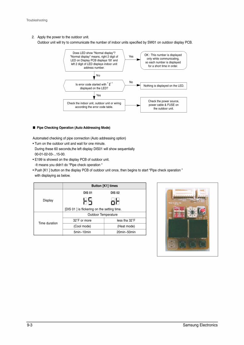
2. Apply the power to the outdoor unit.Outdoor unit will try to communicate the number of indoor units specified by SW01 on outdoor display PCB.
OK : This number is displayed only while communicating,
so each number is displayed for a short time in order.
Nothing is displayed on the LED.
Check the power source, power cable & FUSE on
the outdoor unit.
Yes
No
Yes
N o
Does LED show "Normal display"? "Normal display" means, right 2 digit of LED on Display PCB displays '00' and left 2 digit of LED displays indoor unit
address number.
Is error code started with '' ''
displayed on the LED?
Check the indoor unit, outdoor unit or wiring according the error code table.
■ Pipe Checking Operation (Auto Addressing Mode)
Automated checking of pipe connection (Auto addressing option) • Turn on the outdoor unit and wait for one minute.
During these 60 seconds,the left display DIS01 will show sequentially 00-01-02-03-...15-00.
• E199 is showed on the display PCB of outdoor unit. -It means you didn’t do “Pipe check operation “
• Push [K1 ] button on the display PCB of outdoor unit once, then begins to start “Pipe check operation ” with displaying as below.
Button [K1] times
Display
[DIS 01 ] is flickering on the setting time.
DIS 01 DIS 02
Outdoor Temperature
Time duration 32˚F or more less tha 32˚F
(Cool mode) (Heat mode)
5min~10min 20min~50min
Samsung Electronics 9-3
2. - 2. - 2. -
✳
✳
✳
✳
✳ •✳ •✳ •✳ •✳ •✳
Troubleshooting
✳ Expected time of 4 indoor units installation. • [DIS02 ] shows the indoor unit under searching • It could take more time depending on the indoor and outdoor temperature. • After completeing pipe check operation,it shows “ “ on the display PCB. • The left display DIS01 will show sequentially the following message:
00 -Estabilished communication with indoor unit “A ”;01 -Estabilished communication with indoor unit “B ”;02 -Estabilished communication with indoor unit “C ”;03 -Estabilished communication with indoor unit “D ”;00 -Estabilished communication with indoor unit “A ”...
• Function of Step 3
Mode Function
Auto Addressing Checking the connection & addressing
Manaul Addressing Checking the connection only
- If the auto addressing does not work according to the indoor unit capacity, model or installation condition,apply the manualaddressing.
✳ When SW01 set "0"on Auto address mode,it means you install the maximum number of indoor unit.1) Installation ID Unit Number=MAX Installation ID Unit Number of OD Unit.
➟ Don't need set SW01.2) Installation ID Unit Number<MAX Installation ID Unit Number of OD Unit.
➟ Pls set SW01 as the number of which you install the indoor unit. ✳ On Manual address mode,you must set SW01 as the number of which you install the indoor unit.
- This mode is for finding the combination between indoor unit and each valve on the outdoor unit. Because refrigerant flow is controlled with EEV in the outdoor, controller should know which EEV will control which indoor unit.
- Once "PIPE CHECK MODE" is done normally, each indoor unit will remember the given address number by the outdoor unit and no need to do this checking. But in case of listed below, PIPE CHECK MODE should be done again.
• Re-install the system (ie.house moving) • Remove indoor unit, Add new indoor unit, Change indoor PCB for repair. • Mode change from "manual addressing" to "auto addressing"
- On this mode the controller will ignore the manual address number set on the rotary switch on the indoor PCB.
- To confirm the indoor address number assigned by this mode, use "TEST MODE" and the address number will be displayed on the LED display on the indoor unit.
Samsung Electronics 9-4

Troubleshooting
■ In case of MANUAL ADDRESSING mode.
Switch Setting and Testing Operation
To complete the installation, perform the following checks and tests to ensure that the air conditioner is operating correctly.
Step 1 Review all the following elements in the installation:
• Installation site strength
• Piping connection tightness to detect any gas leakage
• Connection wiring
• Heat-resistant insulation of the piping
• Drainage
• Earthing wire connection
Step 2 IMPORTANT!
Before selecting switch turn off the system power supply
Switch
Views data display
ex) connecting with 2 indoor units.
Move down the switch nß1
ex) connecting with 2 indoor units.
Indoor unit address
Switch
Views data display
SW02
Manual addressing
Indoor unit address
- Select rotary switch “SW01 ” of outdoor unit display PCB,according to number
of indoor unit connected:
-Move dip switch n°1 of “SW02
-outdoor unit display PCB ” down;
Advise control we are going to proceeed
with manual addressing as follow:
Step 3 Follow of indication reported into table below for indoor unit addressing
Step 4 Turn on the system power supply and waiting for 60 seconds after estabilishing communication between outdoor and
indoor units.
During this phase,the left display of outdoor unit display PCB “DIS01 ” will count fom 00--01--02 to 15.
Estabilished communication the left display will count sequentially:
00--communication with indoor unit A;
01--communication with indoor unit B;
02--communication with indoor unit C;
03--communication with indoor unit D;
✳ In case of Manual address mode,you can do pipe check operation for check whether you connect the pipes correctly or not.
But you need set indoor address switch yourselves.
Samsung Electronics 9-5
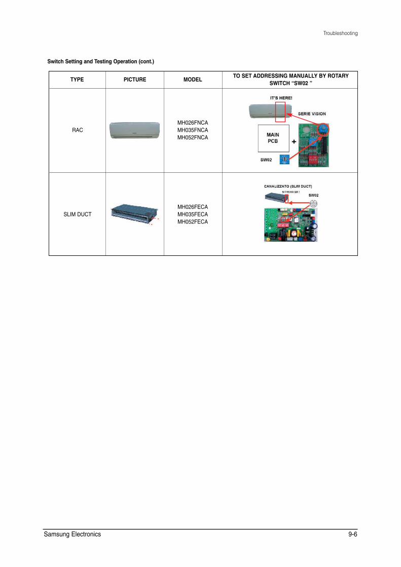
Troubleshooting
Switch Setting and Testing Operation (cont.)
TYPE PICTURE MODEL TO SET ADDRESSING MANUALLY BY ROTARY
SWITCH “SW02 ”
RAC MH026FNCA MH035FNCA MH052FNCA
SLIM DUCT MH026FECA MH035FECA MH052FECA
Samsung Electronics 9-6
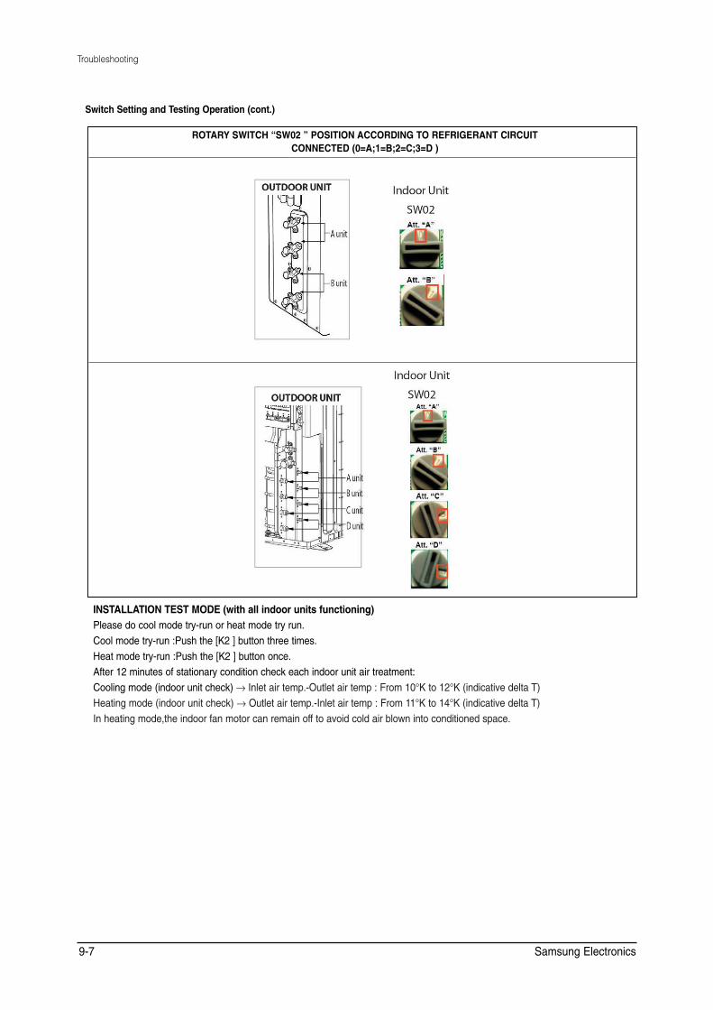
Troubleshooting
Switch Setting and Testing Operation (cont.)
ROTARY SWITCH “SW02 ” POSITION ACCORDING TO REFRIGERANT CIRCUIT CONNECTED (0=A;1=B;2=C;3=D )
INSTALLATION TEST MODE (with all indoor units functioning) Please do cool mode try-run or heat mode try run.Cool mode try-run :Push the [K2 ] button three times.Heat mode try-run :Push the [K2 ] button once.After 12 minutes of stationary condition check each indoor unit air treatment:Cooling mode (indoor unit check) → Inlet air temp.-Outlet air temp : From 10°K to 12°K (indicative delta T)Heating mode (indoor unit check) → Outlet air temp.-Inlet air temp : From 11°K to 14°K (indicative delta T)In heating mode,the indoor fan motor can remain off to avoid cold air blown into conditioned space.
Samsung Electronics 9-7
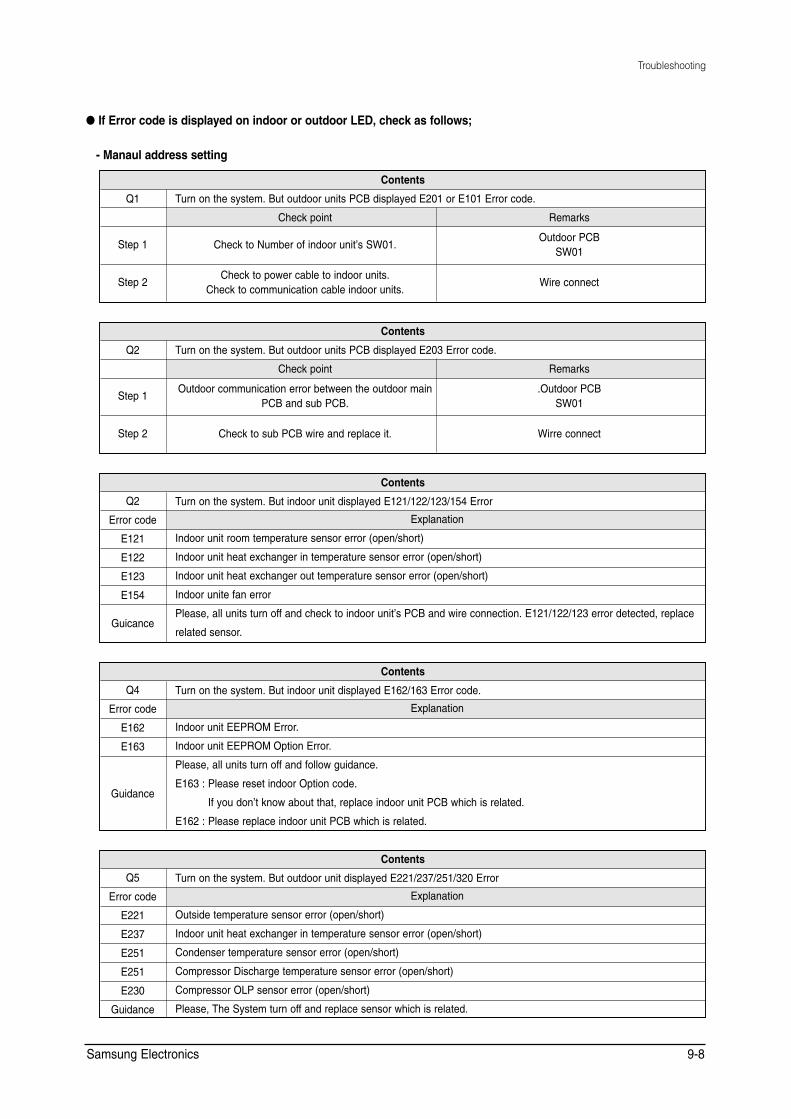
E163 :
Troubleshooting
● If Error code is displayed on indoor or outdoor LED, check as follows;
- Manaul address setting
Contents
Q1 Turn on the system. But outdoor units PCB displayed E201 or E101 Error code.
Check point Remarks
Step 1 Check to Number of indoor unit’s SW01. Outdoor PCB
SW01
Step 2 Check to power cable to indoor units.
Check to communication cable indoor units. Wire connect
Contents
Q2 Turn on the system. But outdoor units PCB displayed E203 Error code.
Check point Remarks
Step 1 Outdoor communication error between the outdoor main
PCB and sub PCB. .Outdoor PCB
SW01
Step 2 Check to sub PCB wire and replace it. Wirre connect
Contents
Q2 Turn on the system. But indoor unit displayed E121/122/123/154 Error
Error code Explanation
E121 Indoor unit room temperature sensor error (open/short)
E122 Indoor unit heat exchanger in temperature sensor error (open/short)
E123 Indoor unit heat exchanger out temperature sensor error (open/short)
E154 Indoor unite fan error
Guicance Please, all units turn off and check to indoor unit’s PCB and wire connection. E121/122/123 error detected, replace
related sensor.
Contents
Q4 Turn on the system. But indoor unit displayed E162/163 Error code.
Error code Explanation
E162 Indoor unit EEPROM Error.
E163 Indoor unit EEPROM Option Error.
Guidance
Please, all units turn off and follow guidance.
E163 : Please reset indoor Option code.
If you don’t know about that, replace indoor unit PCB which is related.
E162 : Please replace indoor unit PCB which is related.
Contents
Q5 Turn on the system. But outdoor unit displayed E221/237/251/320 Error
Error code Explanation
E221 Outside temperature sensor error (open/short)
E237 Indoor unit heat exchanger in temperature sensor error (open/short)
E251 Condenser temperature sensor error (open/short)
E251 Compressor Discharge temperature sensor error (open/short)
E230 Compressor OLP sensor error (open/short)
Guidance Please, The System turn off and replace sensor which is related.
Samsung Electronics 9-8
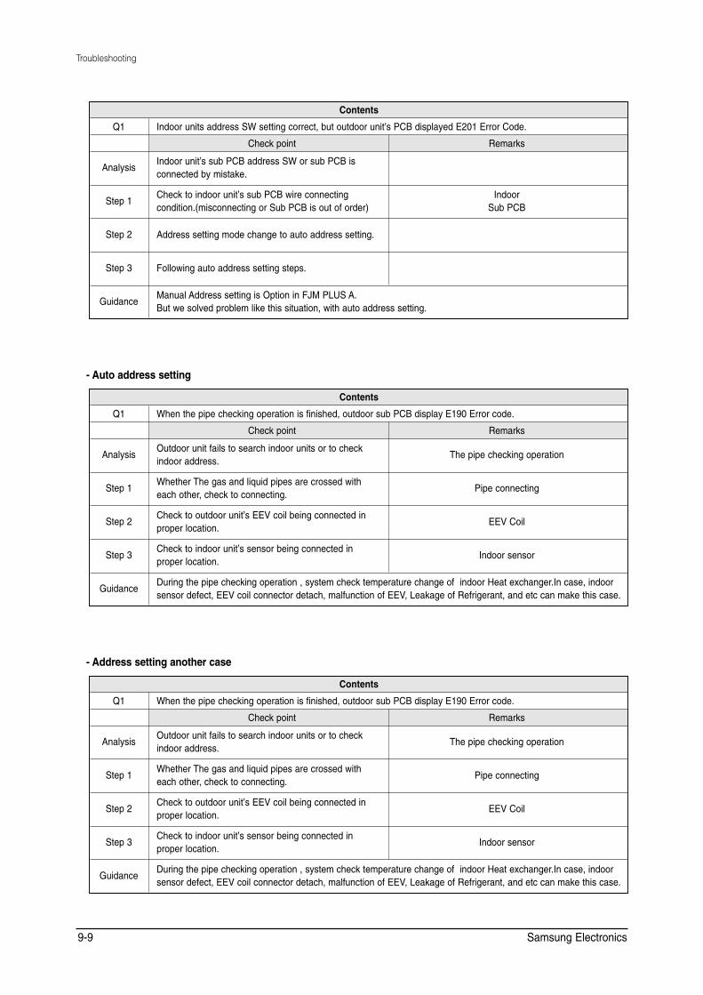
Troubleshooting
Contents
Q1 Indoor units address SW setting correct, but outdoor unit’s PCB displayed E201 Error Code.
Check point Remarks
Analysis Indoor unit’s sub PCB address SW or sub PCB is connected by mistake.
Step 1 Check to indoor unit’s sub PCB wire connecting condition.(misconnecting or Sub PCB is out of order)
Indoor Sub PCB
Step 2 Address setting mode change to auto address setting.
Step 3 Following auto address setting steps.
Guidance Manual Address setting is Option in FJM PLUS A. But we solved problem like this situation, with auto address setting.
- Auto address setting
Contents
Q1 When the pipe checking operation is finished, outdoor sub PCB display E190 Error code.
Check point Remarks
Analysis Outdoor unit fails to search indoor units or to check indoor address.
The pipe checking operation
Step 1 Whether The gas and liquid pipes are crossed with each other, check to connecting.
Pipe connecting
Step 2 Check to outdoor unit’s EEV coil being connected in proper location.
EEV Coil
Step 3 Check to indoor unit’s sensor being connected in proper location.
Indoor sensor
Guidance During the pipe checking operation , system check temperature change of indoor Heat exchanger.In case, indoor sensor defect, EEV coil connector detach, malfunction of EEV, Leakage of Refrigerant, and etc can make this case.
- Address setting another case
Contents
Q1 When the pipe checking operation is finished, outdoor sub PCB display E190 Error code.
Check point Remarks
Analysis Outdoor unit fails to search indoor units or to check indoor address.
The pipe checking operation
Step 1 Whether The gas and liquid pipes are crossed with each other, check to connecting.
Pipe connecting
Step 2 Check to outdoor unit’s EEV coil being connected in proper location.
EEV Coil
Step 3 Check to indoor unit’s sensor being connected in proper location.
Indoor sensor
Guidance During the pipe checking operation , system check temperature change of indoor Heat exchanger.In case, indoor sensor defect, EEV coil connector detach, malfunction of EEV, Leakage of Refrigerant, and etc can make this case.
Samsung Electronics 9-9
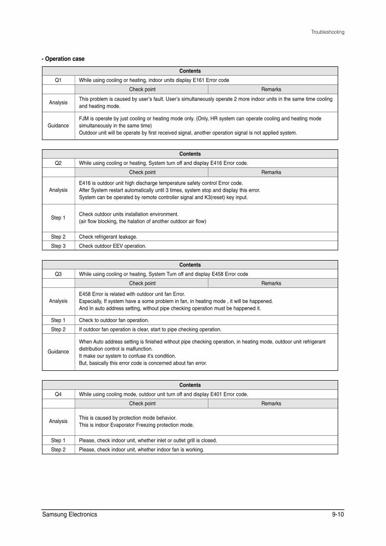
Troubleshooting
- Operation case
Contents
Q1 While using cooling or heating, indoor units display E161 Error code
Check point Remarks
Analysis This problem is caused by user’s fault. User’s simultaneously operate 2 more indoor units in the same time cooling and heating mode.
Guidance FJM is operate by just cooling or heating mode only. (Only, HR system can operate cooling and heating mode simultaneously in the same time) Outdoor unit will be operate by first received signal, another operation signal is not applied system.
Contents
Q2 While using cooling or heating, System turn off and display E416 Error code.
Check point Remarks
Analysis E416 is outdoor unit high discharge temperature safety control Error code. After System restart automatically until 3 times, system stop and display this error. System can be operated by remote controller signal and K3(reset) key input.
Step 1 Check outdoor units installation environment. (air flow blocking, the halation of another outdoor air flow)
Step 2 Check refrigerant leakage.
Step 3 Check outdoor EEV operation.
Contents
Q3 While using cooling or heating, System Turn off and display E458 Error code
Check point Remarks
Analysis E458 Error is related with outdoor unit fan Error. Especially, If system have a some problem in fan, in heating mode , it will be happened. And In auto address setting, without pipe checking operation must be happened it.
Step 1 Check to outdoor fan operation.
Step 2 If outdoor fan operation is clear, start to pipe checking operation.
Guidance
When Auto address setting is finished without pipe checking operation, in heating mode, outdoor unit refrigerant distribution control is malfunction. It make our system to confuse it’s condition. But, basically this error code is concerned about fan error.
Contents
Q4 While using cooling mode, outdoor unit turn off and display E401 Error code.
Check point Remarks
Analysis This is caused by protection mode behavior. This is indoor Evaporator Freezing protection mode.
Step 1 Please, check indoor unit, whether inlet or outlet grill is closed.
Step 2 Please, check indoor unit, whether indoor fan is working.
Samsung Electronics 9-10

Troubleshooting
Contents
Q5 When system start in cooling mode, System don’t operate and display E441 Error code
Check point Remarks
Analysis FJM PLUS is able to operate by -10˚C But we admit that minimum Cooling temperature is by -5˚C Please, Remember cooling operation range.
Contents
Q6 While using heating, outdoor unit turn off and display E404 Error code.
Check point Remarks
Analysis Heating overload safety mode make this situation. After System restart automatically until 3 times, System display this error code and stop. System can operate by remote controller input signal or K3(reset) key input.
Step 1 Check indoor units air flow.
Step 2 Check outdoor unit air flow and installation (outdoor air flow blocking & over charging)
Contents
Q7 When system start in Heating mode, System don’t operate and display E440 Error code.
Check point Remarks
Analysis FJM PLUS is able to operate up to 30˚C But we admit that Maximum Heating temperature is up to 24˚C Please, Remember Heating operation range.
- Try-run Check Error
Contents
Q8 While the system is working try-run mode, system turn off and display E128 / 129 / 246 / 261 / 419 / 422 / 554 Error code.
Check point Remarks
Analysis These Error codes only apply with Try-run mode, in case of system have some defect as result of try-run operation. ✳ Refer to self-detection algorithm (Check Error Code meaning and check it out)
Samsung Electronics 9-11
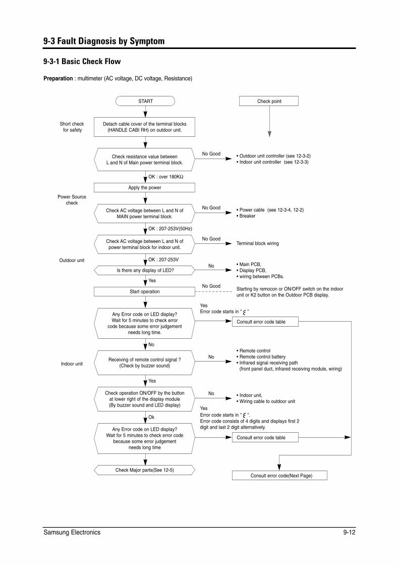
9-3 Fault Diagnosis by Symptom
9-3-1 Basic Check Flow
Preparation : multimeter (AC voltage, DC voltage, Resistance)
Short checkfor safety
Check point
No Good • Outdoor unit controller (see 12-3-2)
OK : 207-253V
Detach cable cover of the terminal blocks (HANDLE CABI RH) on outdoor unit.
Check resistance value between L and N of Main power terminal block.
Apply the power
Check AC voltage between L and N of MAIN power terminal block.
Check AC voltage between L and N of power terminal block for indoor unit.
Is there any display of LED?
START
• Indoor unit controller (see 12-3-3)
OK : over 180KΩ
Power Source check
No Good • Power cable (see 12-3-4, 12-2) • Breaker
OK : 207-253V(50Hz)
No Good Terminal block wiring
Outdoor unit No • Main PCB,
• Display PCB, • wiring between PCBs.
Yes No Good Starting by remocon or ON/OFF switch on the indoor
unit or K2 button on the Outdoor PCB display.
YesError code starts in '' ''
No
Indoor unit
Yes
Consult error code table
Yes Error code starts in '' ''. Error code consists of 4 digits and displays first 2 digit and last 2 digit alternatively.
Consult error code table
Wait for 5 minutes to check error
No • Remote control • Remote control battery • Infrared signal receiving path
(front panel duct, infrared receiving module, wiring)
No • Indoor unit, • Wiring cable to outdoor unit
Start operation
Any Error code on LED display?
code because some error judgement needs long time.
Receiving of remote control signal ? (Check by buzzer sound)
Consult error code(Next Page)
Ok
Check operation ON/OFF by the button at lower right of the display module (By buzzer sound and LED display)
Any Error code on LED display? Wait for 5 minutes to check error code
because some error judgement needs long time
Check Major parts(See 12-5)
Samsung Electronics 9-12
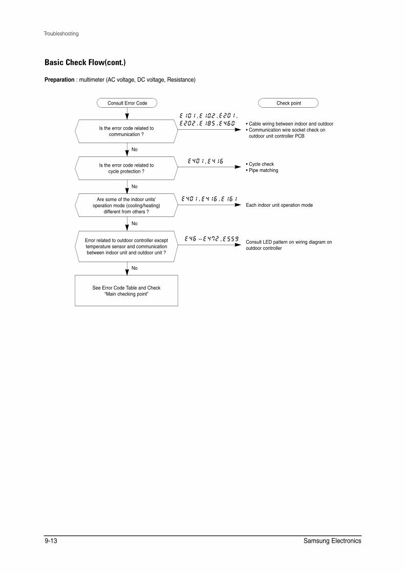
Troubleshooting
Basic Check Flow(cont.)
Preparation : multimeter (AC voltage, DC voltage, Resistance)
• Cable wiring between indoor and outdoor • Communication wire socket check on
outdoor unit controller PCB
• Cycle check • Pipe matching
Each indoor unit operation mode
Consult LED pattern on wiring diagram on outdoor controller
No
No
No
No
Is the error code related to cycle protection ?
Are some of the indoor units’ operation mode (cooling/heating)
different from others ?
Error related to outdoor controller except temperature sensor and communication between indoor unit and outdoor unit ?
See Error Code Table and Check “Main checking point”
Is the error code related to communication ?
Consult Error Code Check point
, , , , ,
-- ,
,
, ,
Samsung Electronics 9-13
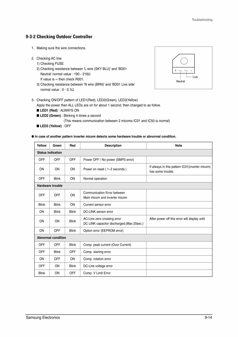
Troubleshooting
9-3-2 Checking Outdoor Controller
1. Making sure the wire connections.
2. Checking AC line1) Checking FUSE2) Checking resistance between 'L wire (SKY BLU)' and 'BD01
Neutral' normal value : 190 - 210Ω Live
If value is ∞ then check R001. Neutral
3) Checking resistance between 'N wire (BRN)' and 'BD01 Live side'normal value : 0 - 0.1Ω
3. Checking ON/OFF pattern of LED1(Red), LED2(Green), LED3(Yellow) Apply the power then ALL LEDs are on for about 1 second. then changed to as follow.■ LED1 (Red) : ALWAYS ON ■ LED2 (Green) : Blinking 4 times a second
(This means communication between 2 micoms IC01 and IC50 is normal) ■ LED3 (Yellow) : OFF
● In case of another pattern inverter micom detects some hardware trouble or abnormal condition.
Yellow Green Red Description Note
Status indication
OFF OFF OFF Power OFF / No power (SMPS error)
ON ON ON Power on reset ( 1~2 seconds ) If always in this pattern IC01(inverter micom) has some trouble.
OFF Blink ON Normal operation
Hardware trouble
OFF OFF ON Communication Error between Main micom and inverter micom
Blink Blink ON Current sensor error
ON Blink Blink DC-LINK sensor error
ON ON Blink AC-Line zero crossing error DC LINK capacitor discharged.(Max 20sec.)
After power off this error will display until
ON OFF Blink Option error (EEPROM error)
Abnormal condition
OFF OFF Blink Comp. peak current (Over Current)
OFF Blink OFF Comp. starting error
ON OFF ON Comp. rotation error
OFF ON Blink DC-Link voltage error
Blink ON OFF Comp. V Limit Error
Samsung Electronics 9-14
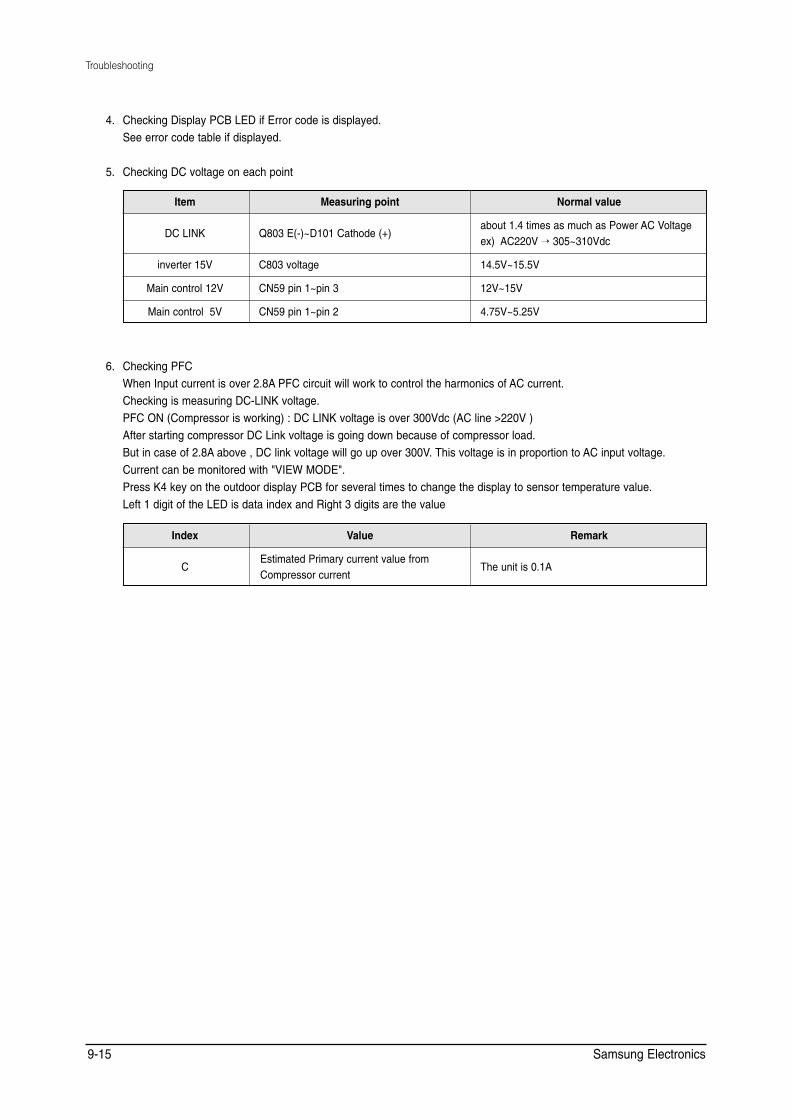
6.
Troubleshooting
4. Checking Display PCB LED if Error code is displayed. See error code table if displayed.
5. Checking DC voltage on each point
Item Measuring point Normal value
DC LINK Q803 E(-)~D101 Cathode (+) about 1.4 times as much as Power AC Voltage ex) AC220V → 305~310Vdc
inverter 15V C803 voltage 14.5V~15.5V
Main control 12V CN59 pin 1~pin 3 12V~15V
Main control 5V CN59 pin 1~pin 2 4.75V~5.25V
6. Checking PFC When Input current is over 2.8A PFC circuit will work to control the harmonics of AC current. Checking is measuring DC-LINK voltage. PFC ON (Compressor is working) : DC LINK voltage is over 300Vdc (AC line >220V ) After starting compressor DC Link voltage is going down because of compressor load. But in case of 2.8A above , DC link voltage will go up over 300V. This voltage is in proportion to AC input voltage. Current can be monitored with "VIEW MODE". Press K4 key on the outdoor display PCB for several times to change the display to sensor temperature value. Left 1 digit of the LED is data index and Right 3 digits are the value
Index Value Remark
C Estimated Primary current value from
The unit is 0.1ACompressor current
Samsung Electronics 9-15
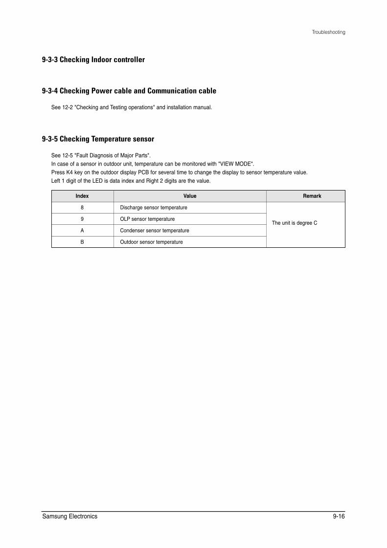
Troubleshooting
9-3-3 Checking Indoor controller
9-3-4 Checking Power cable and Communication cable
See 12-2 "Checking and Testing operations" and installation manual.
9-3-5 Checking Temperature sensor
See 12-5 "Fault Diagnosis of Major Parts".In case of a sensor in outdoor unit, temperature can be monitored with "VIEW MODE".Press K4 key on the outdoor display PCB for several time to change the display to sensor temperature value.Left 1 digit of the LED is data index and Right 2 digits are the value.
Index Value Remark
8 Discharge sensor temperature
The unit is degree C9 OLP sensor temperature
A Condenser sensor temperature
B Outdoor sensor temperature
Samsung Electronics 9-16
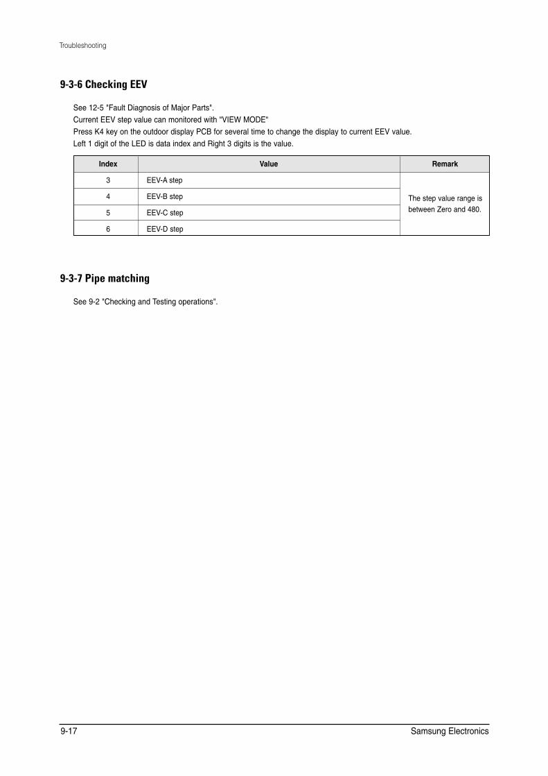
Troubleshooting
������ DA?GEJC�""3
5GG�������(CWNV�&KCIPQUKU�QH�/CLQT�2CTVU�� %WTTGPV�''8�UVGR�XCNWG�ECP�OQPKVQTGF�YKVJ��8+'9�/1&'� 2TGUU�-��MG[�QP�VJG�QWVFQQT�FKURNC[�2%$�HQT�UGXGTCN�VKOG�VQ�EJCPIG�VJG�FKURNC[�VQ�EWTTGPV�''8�XCNWG� .GHV���FKIKV�QH�VJG�.'&�KU�FCVC�KPFGZ�CPF�4KIJV���FKIKVU�KU�VJG�XCNWG�
Index Value Remark
3 EEV-A step
The step value range is between Zero and 480.
4 EEV-B step
5 EEV-C step
6 EEV-D step
������-ELA�I=P?DEJC
5GG �����%JGEMKPI�CPF�6GUVKPI�QRGTCVKQPU��
Samsung Electronics 9-17
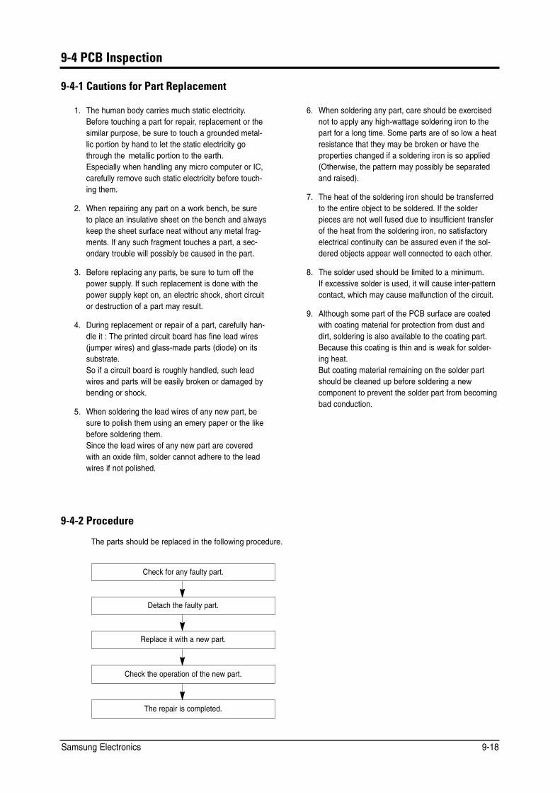
12-4-2
9-4 PCB Inspection
9-4-1 Cautions for Part Replacement
1. The human body carries much static electricity. Before touching a part for repair, replacement or the similar purpose, be sure to touch a grounded metallic portion by hand to let the static electricity go through the metallic portion to the earth. Especially when handling any micro computer or IC, carefully remove such static electricity before touching them.
2. When repairing any part on a work bench, be sure to place an insulative sheet on the bench and always keep the sheet surface neat without any metal fragments. If any such fragment touches a part, a secondary trouble will possibly be caused in the part.
3. Before replacing any parts, be sure to turn off the power supply. If such replacement is done with the power supply kept on, an electric shock, short circuit or destruction of a part may result.
4. During replacement or repair of a part, carefully handle it : The printed circuit board has fine lead wires (jumper wires) and glass-made parts (diode) on its substrate. So if a circuit board is roughly handled, such lead wires and parts will be easily broken or damaged by bending or shock.
5. When soldering the lead wires of any new part, be sure to polish them using an emery paper or the like before soldering them. Since the lead wires of any new part are covered with an oxide film, solder cannot adhere to the lead wires if not polished.
9-4-2 Procedure
The parts should be replaced in the following procedure.
6. When soldering any part, care should be exercised not to apply any high-wattage soldering iron to the part for a long time. Some parts are of so low a heat resistance that they may be broken or have the properties changed if a soldering iron is so applied (Otherwise, the pattern may possibly be separated and raised).
7. The heat of the soldering iron should be transferred to the entire object to be soldered. If the solder pieces are not well fused due to insufficient transfer of the heat from the soldering iron, no satisfactory electrical continuity can be assured even if the soldered objects appear well connected to each other.
8. The solder used should be limited to a minimum. If excessive solder is used, it will cause inter-pattern contact, which may cause malfunction of the circuit.
9. Although some part of the PCB surface are coated with coating material for protection from dust and dirt, soldering is also available to the coating part. Because this coating is thin and is weak for soldering heat. But coating material remaining on the solder part should be cleaned up before soldering a new component to prevent the solder part from becoming bad conduction.
The repair is completed.
Check the operation of the new part.
Replace it with a new part.
Detach the faulty part.
Check for any faulty part.
Samsung Electronics 9-18
10. Reference for Installation
10-1 Selecting Area for Installation
Select an area for installation that is suitable to customer’s needs.
10-1-1 Indoor Unit
1. Make sure that you install the indoor unit in an area providing good ventilation.It must not be blocked by an obstacle affecting the airflow near the air inlet and the air outlet.
2. Make sure that you install the indoor unit in an area allowing good air handling and endurance of vibration of the indoor unit.
3. Make sure that you install the indoor unit in an area where there is no source of heat or vapor nearby.
4. Make sure that you install the indoor unit in an area from which hot or cool air is spread evenly in a room.
5. Make sure that you install the indoor unit in an area away from TVs, audio units, cordless phones, fluorescent lighting fixtures and other electrical appliances (at least 3.3ft).
6. Make sure that you install the indoor unit in an area which provides easy pipe connection with the outdoor unit, and easy drainage for condensed water.
7. Make sure that you install the indoor unit in an area which is large enough to accommodate the measurements shown in figure on the next page.
• It is harmful to the air conditioner if it is used in the following environments: greasy areas (including areas near machines), salty areas such as coast areas, areas where sulfuric gas is present such as hot spring areas. Contact your dealer for advice.
Samsung Electronics 10-1
Reference for Installation
10-1-2 Outdoor Unit
1. Make sure that you install the outdoor unit in area not exposed to the rain or direct sun light.(Install a separate sunblind if exposed to direct sun light.)
2. Make sure that you install the outdoor unit in area allowing the good air moment, not amplifying noise or vibration, especially to avoid disturbing neighbors. (Fix the unit firmly if it is mounted in a high place.)
3. Make sure that you install the outdoor unit in area providing the good ventilation and which is not dusty. It must not be blocked by any obstacle affecting the airflow near the air inlet and the air outlet.
4. Make sure that you install the outdoor unit in area free from animals or plants.
5. Make sure that you install the outdoor unit in area not blocking the traffic.
6. Make sure that you install the outdoor unit in area easy to drain condensed water from the indoor unit.
7. Make sure that you install the outdoor unit in area which provides easy connection within the maximum allowable length of a coolant pipe. If you install the excessive length of pipe, add additional refrigerant as 0.11 oz per unit ft; refer to the table below.
/QFGN 6QVCN�EQPPGEVKPI�RKRG�NGPIVJ.� #FFKPI�TGHTKIGTCPV
/*���(:%#�# .6ŭ����HV %JCTIGNGUU
.6 ����HV .6�����HV�Z�����Q\
/*���(:%#�# .6ŭ�����HV %JCTIGNGUU
.6 �����HV .6������HV�Z�����Q\
8. Make sure that you install the outdoor unit in an area which is large enough to accommodate the measurements shown in figure on the next page.
10-1-3 Remote Control Unit
1. Make sure that you use the remote control unit in an area free from obstacles such as curtains etc, which may block signals from the remote control unit.
2. Make sure that you put the remote control unit in an area not exposed to direct sunlight, and where there is no source of heat.
3. Make sure that you use the remote control unit in an area away from TVs, audio units, cordless phones, fluorescent lighting fixtures and other electrical appliances (at least 3.3ft).
Samsung Electronics 10-2

10-2 Connecting Up and Purging the Circuit
• The air in the indoor unit and in the pipe must be purged. If air remains in the refrigeration pipes, it will affect the compressor, reduce to cooling capacity and could lead to a malfunction. Refrigerant for air purging is not charged in the outdoor unit. Use Vacuum Pump as shown at the right figure. Each unit must be purged in turn.
■ MH050FXCA2A
1. Check the piping connections.
2. Connect the charging hose of low pressure side of manifold gauge to the packed valve having a service port (3/8" service valve) as shown at the figure.
3. Open the valve of the low pressure side of manifold gauge counter-Indoor
clockwise. A-unit Indoor B-unit4. Purge the air from the system using vacuum pump for about 10 minutes.
• Close the valve of the low pressure side of manifold gauge clockwise. Vacuum
• Make sure that pressure gauge show -0.1MPa(-76cmHg) after about Pump
10 minutes. • This procedure is very important in order to avoid gas leak. • Turn off the vacuum pump • Remove the hose of the low pressure side of manifold gauge.
5. Set valve cork of both liquid side and gas side of packed valve to the Valve stem open position.
Stem cap
6. Mount the valve stem nuts and the service port cap to the valve, and tighten them at the torque of 183kgf•cm with a torque wrench.
Service port
7. Check for gas leakage. • At this time, especially check for gas leakage from the 3 way valve’s
stem nuts, and from the service port cap.
10-3 Samsung Electronics

Reference for Installation
■ MH080FXCA4A
1 Check the piping connections.
2 Connect the charging hose of low pressure side of manifold gauge to thepacked valve having a service port (5/8” Packed valve)as shown at thefigure (Value stem:1/2”-20UNF).
WARNING:Make the electrical connection and leave the system into “stand by
A mode”. Do not turn on the system!. B
C
This is necessary for better vacuum operation (full OPEN position of Electronic Expansion Valve -EEV -). Vacuum
Pump
3 Open the valve of the low pressure side of manifold gauge ounterclockwise.
4 Purge the air from the system using vacuum pump for about 30 minutes. - Close the valve of the low pressure side of manifold gauge clockwise. - Make sure that pressure gauge show -0.1MPa(-76cmHg)after about Valve stem
30 minutes.This procedure is very important in order to avoid gas leak.
- Turn off the vacuum pump. Stem cap
- Remove the hose of the low pressure side of manifold gauge.
5 Set valve cork of both liquid side and gas side of packed valve to the Service port
open position.
6 Mount the valve stem nuts and the service port cap to the valve,andtighten them at the torque of 183kgf•cm with a torque wrench.
7 Check for gas leakage. - At this time,especially check for gas leakage from the 3-way valve ’s
stem nuts,and from the service port cap.
Samsung Electronics 10-4
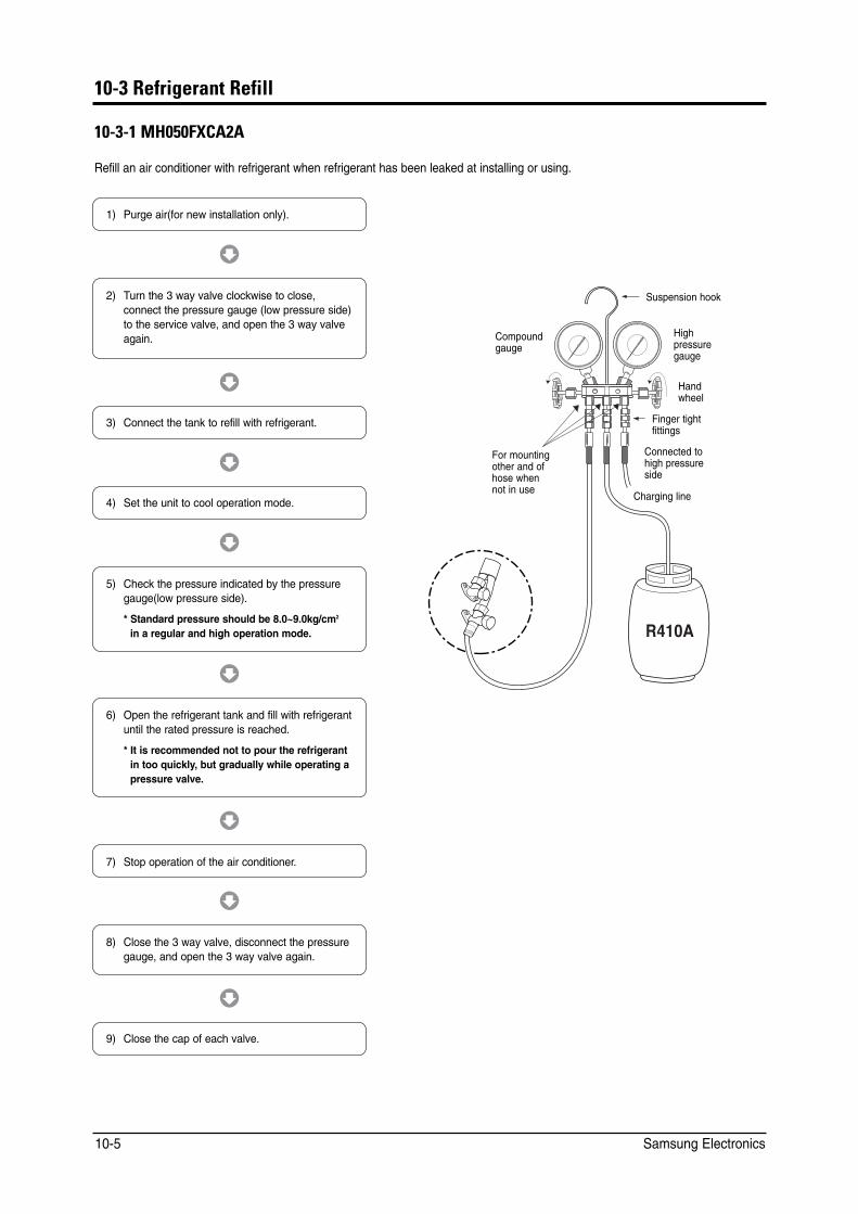
10-3 Refrigerant Refill
10-3-1 MH050FXCA2A
Refill an air conditioner with refrigerant when refrigerant has been leaked at installing or using.
1) Purge air(for new installation only).
3) Connect the tank to refill with refrigerant.
4) Set the unit to cool operation mode.
7) Stop operation of the air conditioner.
9) Close the cap of each valve.
2) Turn the 3 way valve clockwise to close, connect the pressure gauge (low pressure side) to the service valve, and open the 3 way valve again.
5) Check the pressure indicated by the pressure gauge(low pressure side).
* Standard pressure should be 8.0~9.0kg/cm2
in a regular and high operation mode.
6) Open the refrigerant tank and fill with refrigerant until the rated pressure is reached.
* It is recommended not to pour the refrigerant in too quickly, but gradually while operating a pressure valve.
8) Close the 3 way valve, disconnect the pressure gauge, and open the 3 way valve again.
Suspension hook
High pressure gauge
Hand wheel
Finger tight fittings
Connected to high pressure side
Charging line
For mounting other and of hose when not in use
Compound gauge
Samsung Electronics 10-5
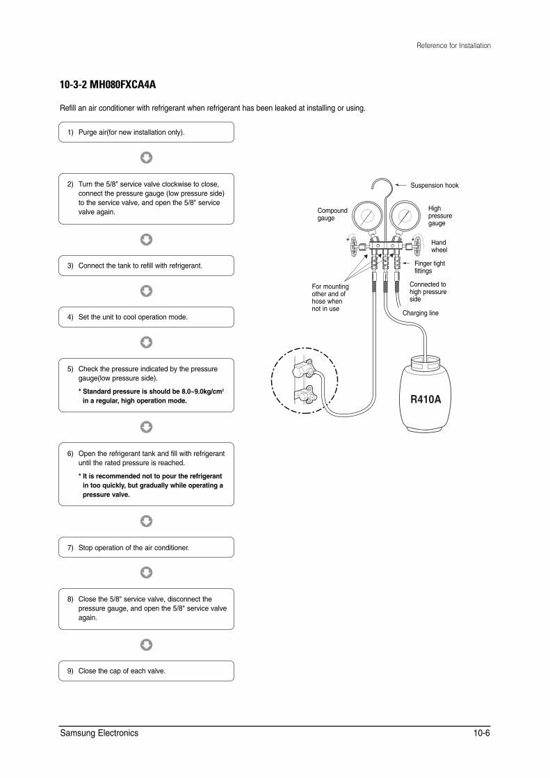
Reference for Installation
10-3-2 MH080FXCA4A
Refill an air conditioner with refrigerant when refrigerant has been leaked at installing or using.
1) Purge air(for new installation only).
3) Connect the tank to refill with refrigerant.
4) Set the unit to cool operation mode.
7) Stop operation of the air conditioner.
9) Close the cap of each valve.
2) Turn the 5/8" service valve clockwise to close, connect the pressure gauge (low pressure side) to the service valve, and open the 5/8" service valve again.
5) Check the pressure indicated by the pressure gauge(low pressure side).
* Standard pressure is should be 8.0~9.0kg/cm2
in a regular, high operation mode.
6) Open the refrigerant tank and fill with refrigerant until the rated pressure is reached.
* It is recommended not to pour the refrigerant in too quickly, but gradually while operating a pressure valve.
8) Close the 5/8" service valve, disconnect the pressure gauge, and open the 5/8" service valve again.
Suspension hook
High pressure gauge
Hand wheel
Finger tight fittings
Connected to high pressure side
Charging line
For mounting other and of hose when not in use
Compound gauge
Samsung Electronics 10-6
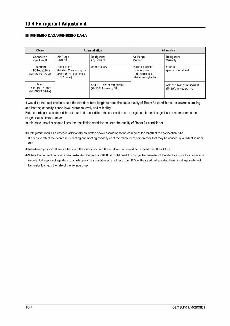
�����/ABNECAN=JP��@FQOPIAJP
*%�5�#5C��A�*%�8�#5C�4A
%NCUU #V�KPUVCNNCVKQP #V�UGTXKEG
%QPPGEVKQP 2KRG�.GPIVJ
#KT�2WTIG /GVJQF
4GHTKIGTCPV #FLWUVOGPV
#KT�2WTIG /GVJQF
4GHTKIGTCPV 3WCPVKV[
5VCPFCTF ��616#. b ��O /*���(:%#�#�
4GHGT�VQ�VJG FGVCKNGF�%QPPGEVKPI�WR CPF�RWTIKPI�VJG�EKTEWKV� �����RCIG�
7PPGEGUUCT[ 2WTIG�CKT�WUKPI�C XCEWWO�RWOR QT�CP�CFFKVKQPCN TGHTKIGTCPV�E[NKPFGT�
TGHGT�VQ URGEKHKECVKQP�UJGGV
/CZ� ��616#. ŭ���O /*���(:%#�#�
#FF������Q\��QH�TGHTKIGTCPV 4���#��HQT�GXGT[��HV�
#FF������Q\��QH�TGHTKIGTCPV 4���#��HQT�GXGT[��HV�
+V�YQWNF�DG�VJG�DGUV�EJQKEG�VQ�WUG�VJG�UVCPFCTF�VWDG�NGPIVJ�VQ�MGGR�VJG�DCUKE�SWCNKV[�QH�4QQO�#KT�EQPFKVKQPGT��HQT�GZCORNG�EQQNKPI
CPF�JGCVKPI�ECRCEKV[��UQWPF�NGXGN��XKDTCVKQP�NGXGN��CPF�TGNKCDKNKV[� $WV��CEEQTFKPI�VQ�C�EGTVCKP�FKHHGTGPV�KPUVCNNCVKQP�EQPFKVKQP��VJG�EQPPGEVKQP�VWDG�NGPIVJ�EQWNF�DG�EJCPIGF�KP�VJG�TGEQOOGPFCVKQP
NGPIVJ�VJCV�KU�UJQYP�CDQXG� +P�VJKU�ECUG��KPUVCNNGT�UJQWNF�MGGR�VJG�KPUVCNNCVKQP�EQPFKVKQP�VQ�MGGR�VJG�SWCNKV[�QH�4QQO�#KT�EQPFKVKQPGT�
4GHTKIGTCPV�UJQWNF�DG�EJCTIGF�CFFKVKQPCNN[�CU�YTKVVGP�CDQXG�CEEQTFKPI�VQ�VJG�EJCPIG�QH�VJG�NGPIVJ�QH�VJG�EQPPGEVKQP�VWDG� +V�PGGFU�VQ�CHHGEV�VJG�FGETGCUG�KP�EQQNKPI�CPF�JGCVKPI�ECRCEKV[�QT�QH�VJG�TGNKCDKNKV[�QH�EQORTGUUQT�VJCV�OC[�DG�ECWUGF�D[�C�NCEM�QH�TGHTKIGT� CPV�
+PUVCNNCVKQP�RQUKVKQP�FKHHGTGPEG�DGVYGGP�VJG�KPFQQT�WPKV�CPF�VJG�QWVFQQT�WPKV�UJQWNF�PQV�GZEGGF�QXGT�VJCP�����HV�
9JGP�VJG�EQPPGEVKQP�RKRG�KU�DGGP�GZVGPFGF�NQPIGT�VJCP�����HV��KV�OKIJV�PGGF�VQ�EJCPIG�VJG�FKCOGVGT�QH�VJG�GNGEVTKECN�YKTG�VQ�C�NCTIGT�UK\G
KP�QTFGT�VQ�MGGR�C�XQNVCIG�FTQR�HQT�UVCTVKPI�TQQO�CKT�EQPFKVKQPGT�KU�PQV�NGUU�VJCP�����QH�VJG�TCVGF�XQNVCIG��#PF�VJGP��C�XQNVCIG�OGVGT�YKNN DG�WUGHWN�VQ�EJGEM�VJG�TCVG�QH�VJG�XQNVCIG�FTQR�
Samsung Electronics 10-7
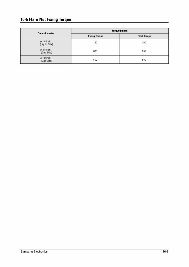
10-5 Flare Nut Fixing Torque
Outer diameter TTorque (kg.cm)cm)orque(kg.
Fixing Torque Final Torque
ø 1/4 inch (Liquid Side)
160 200
ø 3/8 inch (Gas Side) 300 350
ø 1/2 inch (Gas Side) 500 550
Samsung Electronics 10-8
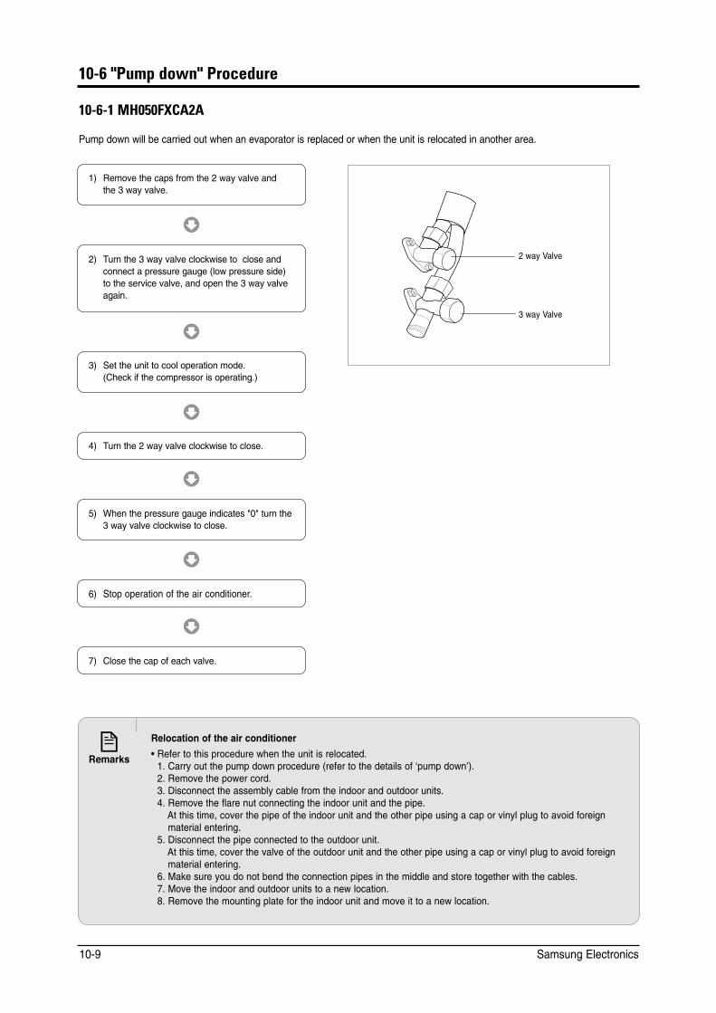
10-6 "Pump down" Procedure
10-6-1 MH050FXCA2A
Pump down will be carried out when an evaporator is replaced or when the unit is relocated in another area.
1) Remove the caps from the 2 way valve and the 3 way valve.
3) Set the unit to cool operation mode. (Check if the compressor is operating.)
4) Turn the 2 way valve clockwise to close.
7) Close the cap of each valve.
2) Turn the 3 way valve clockwise to close and connect a pressure gauge (low pressure side) to the service valve, and open the 3 way valve again.
5) When the pressure gauge indicates "0" turn the 3 way valve clockwise to close.
6) Stop operation of the air conditioner.
2 way Valve
3 way Valve
Relocation of the air conditioner
• Refer to this procedure when the unit is relocated. • 1. Carry out the pump down procedure (refer to the details of ‘pump down’). • 2. Remove the power cord. • 3. Disconnect the assembly cable from the indoor and outdoor units. • 4. Remove the flare nut connecting the indoor unit and the pipe. • 4. At this time, cover the pipe of the indoor unit and the other pipe using a cap or vinyl plug to avoid foreign
material entering. • 5. Disconnect the pipe connected to the outdoor unit. • 4. At this time, cover the valve of the outdoor unit and the other pipe using a cap or vinyl plug to avoid foreign
material entering. • 6. Make sure you do not bend the connection pipes in the middle and store together with the cables. • 7. Move the indoor and outdoor units to a new location. • 8. Remove the mounting plate for the indoor unit and move it to a new location.
Samsung Electronics 10-9
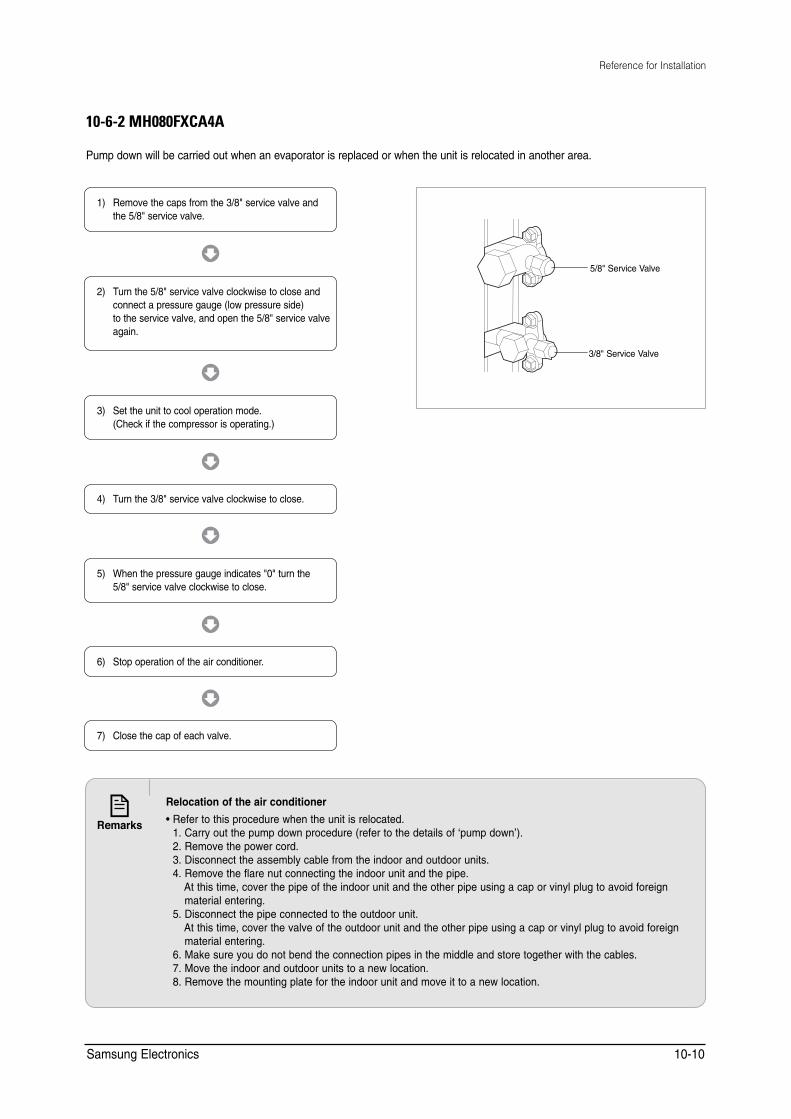
Reference for Installation
10-6-2 MH080FXCA4A
Pump down will be carried out when an evaporator is replaced or when the unit is relocated in another area.
5/8" Service Valve
3/8" Service Valve
1) Remove the caps from the 3/8" service valve and the 5/8" service valve.
3) Set the unit to cool operation mode. (Check if the compressor is operating.)
4) Turn the 3/8" service valve clockwise to close.
7) Close the cap of each valve.
2) Turn the 5/8" service valve clockwise to close and connect a pressure gauge (low pressure side) to the service valve, and open the 5/8" service valve again.
5) When the pressure gauge indicates "0" turn the 5/8" service valve clockwise to close.
6) Stop operation of the air conditioner.
Relocation of the air conditioner
• Refer to this procedure when the unit is relocated. • 1. Carry out the pump down procedure (refer to the details of ‘pump down’). • 2. Remove the power cord. • 3. Disconnect the assembly cable from the indoor and outdoor units. • 4. Remove the flare nut connecting the indoor unit and the pipe. • 4. At this time, cover the pipe of the indoor unit and the other pipe using a cap or vinyl plug to avoid foreign
material entering. • 5. Disconnect the pipe connected to the outdoor unit. • 4. At this time, cover the valve of the outdoor unit and the other pipe using a cap or vinyl plug to avoid foreign
material entering. • 6. Make sure you do not bend the connection pipes in the middle and store together with the cables. • 7. Move the indoor and outdoor units to a new location. • 8. Remove the mounting plate for the indoor unit and move it to a new location.
Samsung Electronics 10-10

11. Reference Information
11-1 Index for Model Name
FREE JOINT MULTI FOR EUROPE
052M H F P E A 4 A / OO O
Rating voltage
A 115V, 60Hz
B 220V, 60Hz
C 208~230V, 60Hz
D 200~220V, 50Hz
E 220~240V, 50Hz
M 127V, 50Hz
Refrigerant
Z R22
C R407C
A R410A
Combination Quantity
_,12.. Indoor
1,2.. Outdoor FJM
Version
_,12.. Indoor
_,A,B.. Outdoor
Indoor/Outdoor Type
Capa
*10Kw(3 digit)
Comp. Type
F Free Inverter
D Redd Digital Scroll
Product Type
M Multi
Mode
C C/O
H H/P
Buyer code
K
S
M
D
E
P
W
V
R
N
X
1 way
Slim 1 way
Mini 4 way
Silhouette
Slim
G-P
HB
Vivave
Moderato
Console
Outdoor
CST
Duct
RAC
CONV
Samsung Electronics 11-1
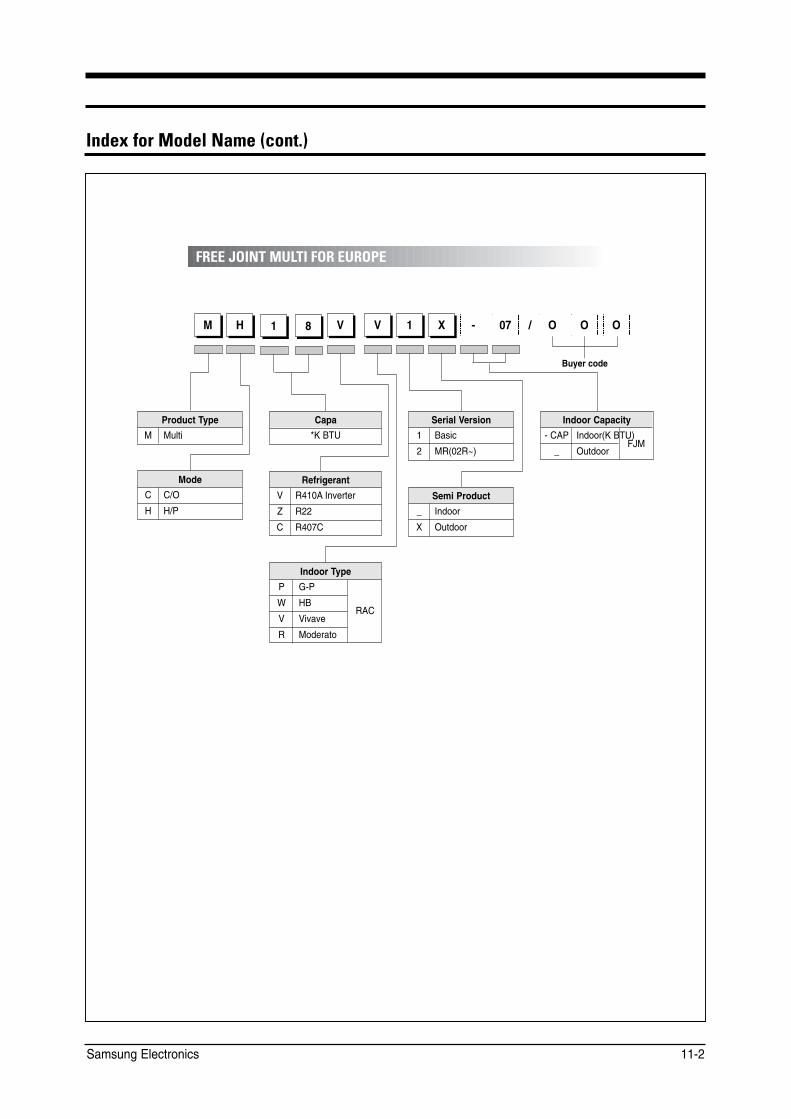
Index for Model Name (cont.)
FREE JOINT MULTI FOR EUROPE
M H 1 8 V V 1 X - 07 / OO O
Indoor Type
P G-P
W HB
V Vivave
R Moderato
Capa
*K BTU
RAC
Product Type
M Multi
Mode
C C/O
H H/P
Buyer code
Refrigerant
V R410A Inverter
Z R22
C R407C
Serial Version
1 Basic
2 MR(02R~)
Semi Product
_ Indoor
X Outdoor
Indoor Capacity
- CAP Indoor(K BTU)
_ Outdoor FJM
Samsung Electronics 11-2

11-2 Refrigerating Cycle Diagram
■ MH050FXCA2A
Samsung Electronics 11-3
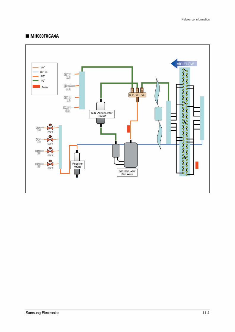
Reference Information
■ MH080FXCA4A
Samsung Electronics 11-4
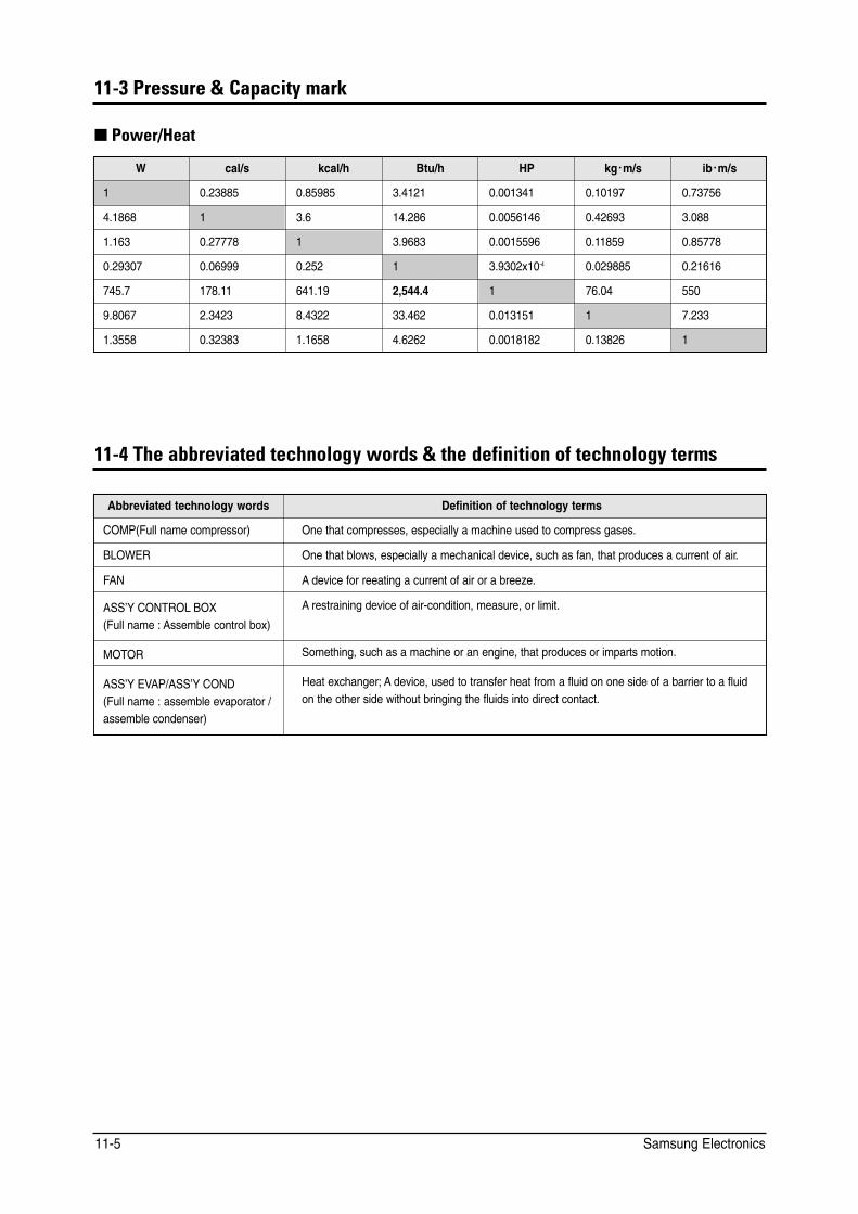
11-3 Pressure & Capacity mark
■ Power/Heat
W cal/s kcal/h Btu/h HP kg.m/s ib.m/s
1 0.23885 0.85985 3.4121 0.001341 0.10197 0.73756
4.1868 1 3.6 14.286 0.0056146 0.42693 3.088
1.163 0.27778 1 3.9683 0.0015596 0.11859 0.85778
0.29307 0.06999 0.252 1 3.9302x10⁻⁴ 0.029885 0.21616
745.7 178.11 641.19 2,544.4 1 76.04 550
9.8067 2.3423 8.4322 33.462 0.013151 1 7.233
1.3558 0.32383 1.1658 4.6262 0.0018182 0.13826 1
11-4 The abbreviated technology words & the definition of technology terms
Abbreviated technology words Definition of technology terms
COMP(Full name compressor) One that compresses, especially a machine used to compress gases.
BLOWER One that blows, especially a mechanical device, such as fan, that produces a current of air.
FAN A device for reeating a current of air or a breeze.
ASS’Y CONTROL BOX (Full name : Assemble control box)
A restraining device of air-condition, measure, or limit.
MOTOR Something, such as a machine or an engine, that produces or imparts motion.
ASS’Y EVAP/ASS’Y COND (Full name : assemble evaporator / assemble condenser)
Heat exchanger; A device, used to transfer heat from a fluid on one side of a barrier to a fluid on the other side without bringing the fluids into direct contact.
Samsung Electronics 11-5
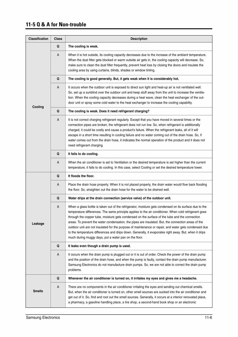
11-5 Q & A for Non-trouble
Classification Class Description
Q The cooling is weak.
A When it is hot outside, its cooling capacity decreases due to the increase of the ambient temperature.
When the dust filter gets blocked or warm outside air gets in, the cooling capacity will decrease. So,
make sure to clean the dust filter frequently, prevent heat loss by closing the doors and insulate the
cooling area by using curtains, blinds, shades or window tinting.
Q The cooling is good generally. But, it gets weak when it is considerably hot.
Cooling
A It occurs when the outdoor unit is exposed to direct sun light and heat-up air is not ventilated well.
So, set up a sunblind over the outdoor unit and keep stuff away from the unit to increase the ventila
tion. When the cooling capacity decreases during a heat wave, clean the heat exchanger of the out
door unit or spray some cold water to the heat exchanger to increase the cooling capability.
Q The cooling is weak. Does it need refrigerant charging?
A It is not correct charging refrigerant regularly. Except that you have moved in several times or the
connection pipes are broken, the refrigerant does not run low. So, when refrigerant is additionally
charged, it could be costly and cause a product's failure. When the refrigerant leaks, all of it will
escape in a short time resulting in cooling failure and no water coming out of the drain hose. So, if
water comes out from the drain hose, it indicates the normal operation of the product and it does not
need refrigerant charging.
Q It fails to do cooling.
A When the air conditioner is set to Ventilation or the desired temperature is set higher than the current
temperature, it fails to do cooling. In this case, select Cooling or set the desired temperature lower.
Q It floods the floor.
A Place the drain hose properly. When it is not placed properly, the drain water would flow back flooding
the floor. So, straighten out the drain hose for the water to be drained well.
Q Water drips at the drain connection (service valve) of the outdoor unit.
Leakage
A When a glass bottle is taken out of the refrigerator, moisture gets condensed on its surface due to the
temperature differences. The same principle applies to the air conditioner. When cold refrigerant goes
through the copper tube, moisture gets condensed on the surface of the tube and the connection
areas. To prevent the water condensation, the pipes are insulated. But, the connection areas of the
outdoor unit are not insulated for the purpose of maintenance or repair, and water gets condensed due
to the temperature differences and drips down. Generally, it evaporates right away. But, when it drips
much during muggy days, put a water pan on the floor.
Q It leaks even though a drain pump is used.
A It occurs when the drain pump is plugged out or it is out of order. Check the power of the drain pump
and the position of the drain hose, and when the pump is faulty, contact the drain pump manufacturer.
Samsung Electronics do not manufacture drain pumps. So, we are not able to correct the drain pump
problems.
Q Whenever the air conditioner is turned on, it irritates my eyes and gives me a headache.
Smells A There are no components in the air conditioner irritating the eyes and sending out chemical smells.
But, when the air conditioner is turned on, other smell sources are sucked into the air conditioner and
get out of it. So, find and root out the smell sources. Generally, it occurs at a interior renovated place,
a pharmacy, a gasoline handling place, a tire shop, a second-hand book shop or an electronic
Samsung Electronics 11-6
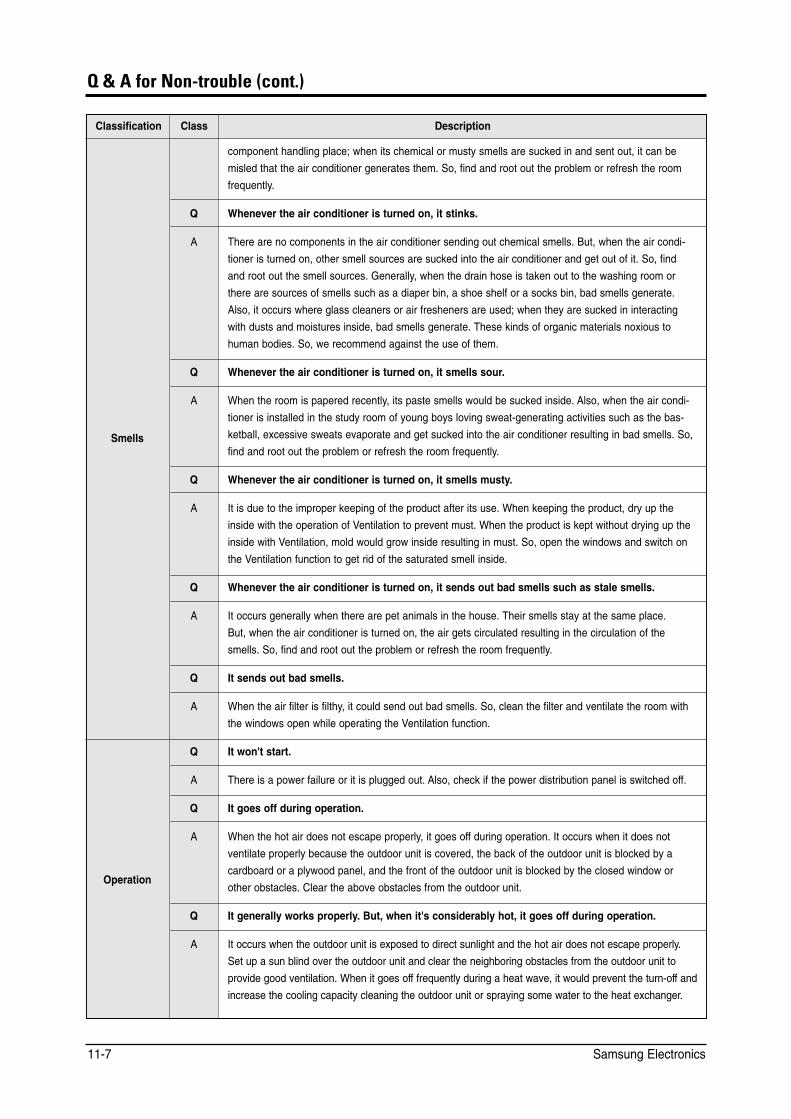
Q & A for Non-trouble (cont.)
Classification Class Description
component handling place; when its chemical or musty smells are sucked in and sent out, it can be
misled that the air conditioner generates them. So, find and root out the problem or refresh the room
frequently.
Q Whenever the air conditioner is turned on, it stinks.
A There are no components in the air conditioner sending out chemical smells. But, when the air condi
tioner is turned on, other smell sources are sucked into the air conditioner and get out of it. So, find
and root out the smell sources. Generally, when the drain hose is taken out to the washing room or
there are sources of smells such as a diaper bin, a shoe shelf or a socks bin, bad smells generate.
Also, it occurs where glass cleaners or air fresheners are used; when they are sucked in interacting
with dusts and moistures inside, bad smells generate. These kinds of organic materials noxious to
human bodies. So, we recommend against the use of them.
Q Whenever the air conditioner is turned on, it smells sour.
Smells
A When the room is papered recently, its paste smells would be sucked inside. Also, when the air condi
tioner is installed in the study room of young boys loving sweat-generating activities such as the bas
ketball, excessive sweats evaporate and get sucked into the air conditioner resulting in bad smells. So,
find and root out the problem or refresh the room frequently.
Q Whenever the air conditioner is turned on, it smells musty.
A It is due to the improper keeping of the product after its use. When keeping the product, dry up the
inside with the operation of Ventilation to prevent must. When the product is kept without drying up the
inside with Ventilation, mold would grow inside resulting in must. So, open the windows and switch on
the Ventilation function to get rid of the saturated smell inside.
Q Whenever the air conditioner is turned on, it sends out bad smells such as stale smells.
A It occurs generally when there are pet animals in the house. Their smells stay at the same place.
But, when the air conditioner is turned on, the air gets circulated resulting in the circulation of the
smells. So, find and root out the problem or refresh the room frequently.
Q It sends out bad smells.
A When the air filter is filthy, it could send out bad smells. So, clean the filter and ventilate the room with
the windows open while operating the Ventilation function.
Q It won't start.
A There is a power failure or it is plugged out. Also, check if the power distribution panel is switched off.
Q It goes off during operation.
Operation
A When the hot air does not escape properly, it goes off during operation. It occurs when it does not
ventilate properly because the outdoor unit is covered, the back of the outdoor unit is blocked by a
cardboard or a plywood panel, and the front of the outdoor unit is blocked by the closed window or
other obstacles. Clear the above obstacles from the outdoor unit.
Q It generally works properly. But, when it's considerably hot, it goes off during operation.
A It occurs when the outdoor unit is exposed to direct sunlight and the hot air does not escape properly.
Set up a sun blind over the outdoor unit and clear the neighboring obstacles from the outdoor unit to
provide good ventilation. When it goes off frequently during a heat wave, it would prevent the turn-off and
increase the cooling capacity cleaning the outdoor unit or spraying some water to the heat exchanger.
Samsung Electronics 11-7
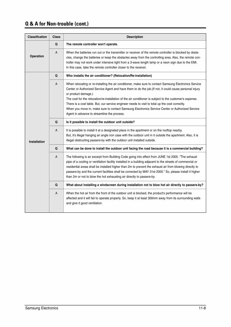
Q & A for Non-trouble (cont.)
Classification Class Description
Q The remote controller won't operate.
Operation A When the batteries run out or the transmitter or receiver of the remote controller is blocked by obsta
cles, change the batteries or keep the obstacles away from the controlling area. Also, the remote con
troller may not work under intensive light from a 3-wave length lamp or a neon sign due to the EMI.
In this case, take the remote controller closer to the receiver.
Q Who installs the air conditioner? (Relocation/Re-installation)
A When relocating or re-installing the air conditioner, make sure to contact Samsung Electronics Service
Center or Authorized Service Agent and have them to do the job.(If not, it could cause personal injury
or product damage.)
The cost for the relocation/re-installation of the air conditioner is subject to the customer's expense.
There is a cost table. But, our service engineer needs to visit to total up the cost correctly.
When you move in, make sure to contact Samsung Electronics Service Center or Authorized Service
Agent in advance to streamline the process.
Q Is it possible to install the outdoor unit outside?
Installation
A It is possible to install it at a designated place in the apartment or on the rooftop nearby.
But, it's illegal hanging an angle iron case with the outdoor unit in it outside the apartment. Also, it is
illegal obstructing passers-by with the outdoor unit installed outside.
Q What can be done to install the outdoor unit facing the road because it is a commercial building?
A The following is an excerpt from Building Code going into effect from JUNE 1st 2005. "The exhaust
pipe of a cooling or ventilation facility installed in a building adjacent to the streets of commercial or
residential areas shall be installed higher than 2m to prevent the exhaust air from blowing directly to
passers-by and the current facilities shall be corrected by MAY 31st 2005." So, please install it higher
than 2m or not to blow the hot exhausting air directly to passers-by.
Q What about installing a windscreen during installation not to blow hot air directly to passers-by?
A When the hot air from the front of the outdoor unit is blocked, the product's performance will be
affected and it will fail to operate properly. So, keep it at least 300mm away from its surrounding walls
and give it good ventilation.
Samsung Electronics 11-8
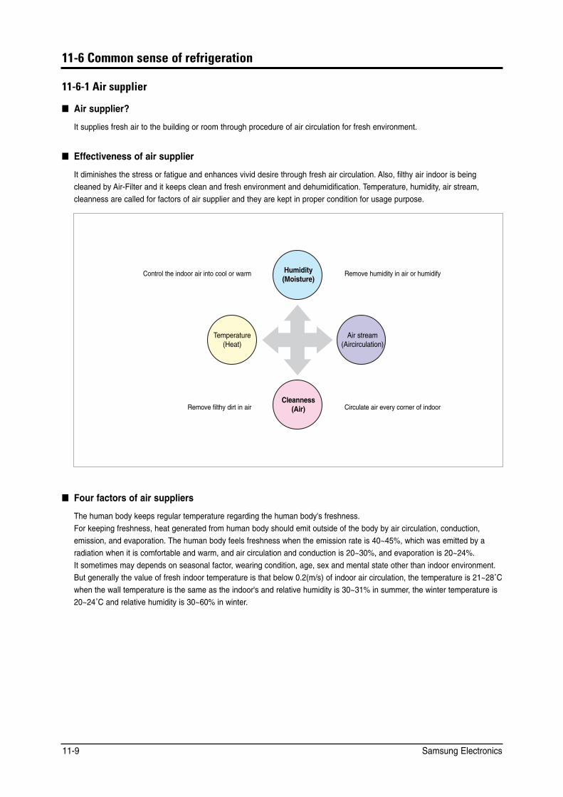
11-6 Common sense of refrigeration
11-6-1 Air supplier
■ Air supplier?
It supplies fresh air to the building or room through procedure of air circulation for fresh environment.
■ Effectiveness of air supplier
It diminishes the stress or fatigue and enhances vivid desire through fresh air circulation. Also, filthy air indoor is being cleaned by Air-Filter and it keeps clean and fresh environment and dehumidification. Temperature, humidity, air stream, cleanness are called for factors of air supplier and they are kept in proper condition for usage purpose.
Humidity (Moisture)
Temperature (Heat)
Air stream (Aircirculation)
Cleanness (Air)
Control the indoor air into cool or warm Remove humidity in air or humidify
Remove filthy dirt in air Circulate air every corner of indoor
■ Four factors of air suppliers
The human body keeps regular temperature regarding the human body's freshness. For keeping freshness, heat generated from human body should emit outside of the body by air circulation, conduction, emission, and evaporation. The human body feels freshness when the emission rate is 40~45%, which was emitted by a radiation when it is comfortable and warm, and air circulation and conduction is 20~30%, and evaporation is 20~24%. It sometimes may depends on seasonal factor, wearing condition, age, sex and mental state other than indoor environment.But generally the value of fresh indoor temperature is that below 0.2(m/s) of indoor air circulation, the temperature is 21~28˚Cwhen the wall temperature is the same as the indoor's and relative humidity is 30~31% in summer, the winter temperature is20~24˚C and relative humidity is 30~60% in winter.
Samsung Electronics 11-9
ELECTRONICS
GSPN(Global Service Partner Network)
Area Web Site
North America http://service.samsungportal.com
Latin America http://latin.samsungportal.com
CIS http://cis.samsungportal.com
Europe http://europe.samsungportal.com
China http://china.samsungportal.com
Asia http://asia.samsungportal.com
Mideast & Africa http://mea.samsungportal.com
This Service Manual is a property of Samsung Electronics Co., Ltd. © Samsung Electronics Co., Ltd. Jan. 2008. Any unauthorized use of Manual can be punished under applicable Printed in Korea. International and/or domestic law. Code No. DB98-29161A(3)