service handbook - state water heaters · service handbook high efficiency commercial gas series....
TRANSCRIPT

1PRINTED 0509 198152-002
COMMERCIAL GAS WATER HEATERS
FOR MODELS:
• SUF60120 • SUF100150 • SUF100199 • SUF100250 • SUF130300 • SUF130400
SERVICE HANDBOOKHIGH EFFICIENCY
COMMERCIAL GAS SERIES

ULTRAFORCE COMMERCIAL GAS WATER HEATERSUF 120 thru 400 SERVICE HANDBOOK
State Water Heaters – Technical Training Department 1 Ashland City, Tennessee © 2009Servicing should only be performed by a Qualified Service Agent 198152-002
TABLE OF CONTENTS
INTRODUCTION...............................................................2QUALIFICATIONS............................................................2 TOOLS REQUIRED.........................................................3GENERAL INFORMATION................................................4GAS PRESSURE SPECIFICATIONS ................................4INSTALLATION QUICK TIPS – SUF 120 and 150 GASPRESSURE .....................................................................5ADJUSTMENT PROCEDURE: .........................................5GAS PRESSURE .............................................................5SUF120 AND 150 MODELS..............................................5HIGH ALTITUDE INSTALLATIONS ...................................5SUF 120 - 150 .................................................................5INSTALLATION QUICK TIPS - SUF 199 AND 250 GASPRESSURE .....................................................................6ADJUSTMENT PROCEDURE:..........................................6GAS PRESSURE .............................................................6SUF 199 AND 250 MODELS ............................................6HIGH ALTITUDE INSTALLATION......................................6INSTALLATION QUICK TIPS - SUF 300, 400 GASPRESSURE......................................................................7ADJUSTMENT PROCEDURE:..........................................7GAS PRESSURE..............................................................7SUF 300,400,....................................................................7HIGH ALTITUDE ADJUSTMENT ......................................7SUF 300,400,....................................................................7INSTALLATION TIPS - SUF 300, 400 ...............................8VENTING TABLES SUF 120 – 250....................................9VENTING TABLES SUF 300,400,.....................................9VENTING - ALL MODELS – SINGLE PIPE POWER VENT –USING ROOM AIR..........................................................10VENTING – ALL MODELS – TWO PIPE DIRECT VENT –USING OUTSIDE AIR.....................................................11VENT TERMINATION – DIRECT VENT – ALL MODELS. .12DIRECT VENTING – ALL MODELS.................................13CONTROL OVERVIEW ..................................................14CONTROL OVERVIEW – ALL MODELS..........................14ADJUSTING TANK TEMPERATURE – OPERATING SETPOINT - DIFFERENTIAL.................................................15CHANGING THE DISPLAY UNITS..................................16FAULT AND WARNING CONDITIONS – ADVANCEDDIAGNOSTIC INFORMATION.........................................17ACCESS TO THE CURRENT FAULT OR WARNING.......18VIEWING THE FAULT HISTORY - VIEWINGINFORMATION ABOUT THE HEATER............................19 CONTROL SEQUENCE (TYPICAL ALL MODELS).........20CONTROL SEQUENCE FLOW CHART...........................21CONTROLS – CENTRAL CONTROL BOARD – CCB ......22CONTROLS – GAS VALVE SUF 120...............................23CONTROLS – GAS VALVE SUF 150...............................23CONTROLS – GAS VALVE SUF 199 and 250..................24ADJUSTMENT PROCEDURE:........................................24GAS PRESSURE ...........................................................24SUF 199 AND 250 MODELS ..........................................24CONTROLS – GAS VALVE SUF 199 and 250..................25
CONTROLS – GAS VALVE , ORIFICE CHART–SUF300,400,...................................................................26CONTROLS – PRESSURE SWITCHES – ALL MODELS..27CONTROLS – PRESSURE SWITCHES – SUF 120 through250.................................................................................28CONTROLS – PRESSURE SWITCHES – SUF 300,400,. .29CONTROLS – CONNECTIONS, IGNITER, FLAMESENSOR, SIGHT GLASS, POWERED ANODES.............30HOT SURFACE IGNITER / FLAME SENSOR / CONTROLTIMING...........................................................................31BLOWER SPEED CONTROL SUF 199 AND 250.............32VARIABLE FREQUENCY DRIVE – SUF 400...................33VARIABLE FREQUENCY DRIVE - BLOWER SPEED ANDPRESSURE READINGS..................................................34WIRING DIAGRAM – SUF 120 – 300 ..............................35WIRING DIAGRAM – SUF 400,.......................................36

ULTRAFORCE COMMERCIAL GAS WATER HEATERSUF 120 thru 400 SERVICE HANDBOOK
State Water Heaters – Technical Training Department 2 Ashland City, Tennessee © 2009Servicing should only be performed by a Qualified Service Agent 198152-002
INTRODUCTION
QUALIFICATIONS
ANSI Z223.1 Sec 3.3.83
"Qualified Agency"
"Any individual, firm, corporation or companythat ei ther i n person o r through arepresentative i s e ngaged i n an d i sresponsible for (a) the installation, testing orreplacement of g as p iping or (b) theconnection, i nstallation, testing, re pair orservicing of appliances and equipment; thatis experienced in such work; that is familiarwith al l precautions required; and that hascomplied w ith al l the re quirements o f theauthority having jurisdiction."
Service of this water heater requires abilityequivalent to th at of a Qual ified S erviceAgent (l icensed t radesman) i n the fi eldinvolved. Installation skills such as plumbing,air supp ly, vent ing, gas s upply, e lectricalsupply are required in addition to e lectricaltesting ski lls. S ome pro ducts m ay requ irecombustion testi ng equipment andcertification. If you do not possess theseskills or do not have the proper tools youshould not attem pt to serv ice thi s w aterheater.
The service handbook is designed to aid inservicing and trou bleshooting S tate W aterHeaters Ultra Force SUF commercial waterheaters i n t he f ield. No duplication orreproduction of t his bo ok m ay be m adewithout the express written authorization ofState Water Heaters .
The fol lowing tex t and i llustrations w illprovide you with a step by step procedure toverify pr oper i nstallation, opera tion, andtroubleshooting procedures. Additional quickreference da ta i s i ncluded to ass ist you inservicing these products.
The information contained in this handbookis designed to answer co mmonly face dsituations enc ountered in the ope ration ofthis product l ine and is not meant to be all
inclusive. If you are experiencing a problemnot covered in this handbook, please contactState Water Heaters Technical Information at1-800-365-0024, by e mail [email protected] or your localState Water Heater representative for furtherassistance.
Our website:www.statewaterheaters.com
is also a resource for installation and serviceinformation. Thi s handbook i s i ntended foruse by licensed plumbing professionals andreference should be made to the installationmanual accom panying the prod uct. Thishandbook contains supplemental informationto the produ ct’s i nstallation and ope rationmanual.

ULTRAFORCE COMMERCIAL GAS WATER HEATERSUF 120 thru 400 SERVICE HANDBOOK
State Water Heaters – Technical Training Department 3 Ashland City, Tennessee © 2009Servicing should only be performed by a Qualified Service Agent 198152-002
TOOLS REQUIRED
● ELECTRICAL MULTIMETER CAPABLE OF MEASURING CONTINUITY/ OHMS, AC& DC VOLTS, AMPERES, MICROAMPERES, MILLIVOLTS, and FREQUENCY(Hz)○ UEi Model DL289 or equivalent
● DIGITAL MANOMETER + 60” W. C. in .01” incrementsNote: A digital manometer is required for testing pressure switches and can replacea gas pressure gauge, draft gauge or slack tube manometer for checking gaspressure.
○ UEi model EM200 or equivalent● WATER PRESSURE GAUGE w/ LAZY HAND AND HOSE BIBB CONNECTION● THERMOMETER● 1-1/16 INCH SOCKET WITH EXTENSION FOR ANODE REPLACEMENT● SET OF NUMBERED DRILL BITS
DIGITAL MANOMETER DIGITAL MULTIMETER
WATER PRESSURETEST GAUGE W/ LAZYHAND AND HOSE BIBB
CONNECTION

ULTRAFORCE COMMERCIAL GAS WATER HEATERSUF 120 thru 400 SERVICE HANDBOOK
State Water Heaters – Technical Training Department 4 Ashland City, Tennessee © 2009Servicing should only be performed by a Qualified Service Agent 198152-002
GENERAL INFORMATION
GAS PRESSURE SPECIFICATIONS
INSTALLATION REQUIREMENTS FOR THECOMMONWEALTH OF MASSACHUSETTSFor al l side w all terminated, hor izontally ventedpower vent, direct vent, and power direct vent gasfueled w ater heat ers installed i n ev ery dwelling,building or structure used in w hole or in part f orresidential pur poses, including t hose ow ned oroperated by the Commonwealth and where the sidewall exhaust vent termination is less than seven (7)feet above finished grade in the area of the venting,including but not limited to decks and porches, thefollowing requirements shall be satisfied:INSTALLATION OF CARBON MONOXIDEDETECTORSAt the time of installation of the side wall horizontalvented gas fueled equipment, the installing plumberor gas fitter shall observe that a hard wired carbonmonoxide detector with an alarm and battery back-up is installed on t he f loor level where t he g asequipment is t o b e i nstalled. In add ition, t heinstalling plumber or gas fitter shall observe that abattery operated or har d w ired carbon monoxidedetector w ith an al arm i s i nstalled on eac hadditional level of the dwelling, building or structureserved by the sidewall horizontal vented gas fueledequipment. It s hall b e the re sponsibility o f theproperty owner to secure the services of qualifiedlicensed pr ofessionals for the i nstallation of har dwired carbon monoxide detectors. In the event thatthe s ide wall hor izontally v ented gas fueled
equipment is installed in a crawl space or an attic,the hard wired carbon monoxide detector with alarmand battery back-up may be installed on the nextadjacent f loor l evel. I n t he e vent t hat therequirements of this subdivision can not be met atthe t ime of c ompletion o f i nstallation, t he ow nershall have a period of thirty (30) days to comply withthe above requirements p rovided that dur ing saidthirty ( 30) day p eriod, a bat tery op erated carbonmonoxide detector with an alarm shall be installedAPPROVED CARBON MONOXIDE DETECTORSEach carbon monoxide de tector as r equired inaccordance with the above provisions shall complywith NFPA 720 and be ANSI/UL 2034 listed andCSA certified.SIGNAGEA m etal or p lastic i dentification plate s hall b epermanently mounted to the exterior of the buildingat a minimum height of eight (8) feet above gradedirectly in line with the exhaust vent terminal for thehorizontally vented gas fueled heating appliance orequipment. The sign shall read, in print size no lessthan one-half (1/2”) inch in size,
“GAS VENT DIRECTLY BELOW. KEEP CLEAROF ALL OBSTRUCTIONS.”
MODELS Natural120-150
Propane120-150
Natural199-250
Propane199-250
Natural300/400/500
Propane300/400/500
Maximum Gas Supply Pressure 10.5” WC(2.59kPa)
14.0“WC( 3.45kPa)
10.5“WC(2.59kPa)
14.0“WC( 3.45kPa)
11.0”WC(2.74kPa)
14.00”WC(3.49kPa)
Nominal Gas Supply Pressure 7.0”WC(1.74kPa)
11.0“WC( 2.74kPa)
7.0“WC(1.74kPa)
11.0“WC( 2.74kPa)
7.0”WC(1.74kPa)
11.0”WC(2.74kPa)
Minimum Gas Supply Pressure(Low Gas Press. SwitchSetting)
4.8”WC(1.20kPa)
8.5“WC( 2.12kPa)
4.8”WC(1.20kPa)
8.5“WC( 2.12kPa)
5.2”WC(1.54kPa)
11.0“WC( 2.74kPa)
Manifold Pressure 4.0”WC(0.98kPa)
10.0“WC(2.49 kPa)
0“WC( 0 kPa)
0“WC( 0 kPa)
4.00“WC( 1.25kPa)
10.0“WC( 2.49kPa)

ULTRAFORCE COMMERCIAL GAS WATER HEATERSUF 120 thru 400 SERVICE HANDBOOK
State Water Heaters – Technical Training Department 5 Ashland City, Tennessee © 2009Servicing should only be performed by a Qualified Service Agent 198152-002
INSTALLATION QUICK TIPS – SUF 120 and 150 GAS PRESSURE
ADJUSTMENT PROCEDURE: GAS PRESSURE SUF120 AND 150 MODELS
Main line gas pressure to the water heater for naturalgas should be between a maximum of 10.5"W.C.(2.59kPa) for natural gas, 14.0"W.C.(3.45kPa) forpropane and a minimum of 4.8W.C.(1.18kPa) forNatural Gas, and 8.5"W.C. (2.08kPa) for PropaneGas.
Also see gas pressure specification table on page 4.
1.Check gas line pressure with a manometer.2.Check manifold pressure gauge (manometer)connected to the manifold pressure tap on the gascontrol valve, If full rate adjustment is required, remove cover screwfrom top of the gas control valve. Using a smallscrewdriver, turn adjusting screw clockwise toincrease or counterclockwise to decrease gaspressure to obtain 4.0" W.C.(1 K pa) for natural gasand 10.0" W.C. (2.5 kPa) for L.P. Gas.
3. Cycle the burner on and off several times to checkits operation.4. Check the operation of the limit and operatingcontrols.5. Check the vent system seams and joints andensure that there is no discharge of flue products intothe room.6. Check the input rate.
HIGH ALTITUDE INSTALLATIONS SUF 120 - 150 For appliance installation locations with elevationsabove 6,500 feet (1982 meters) consult the “HighAltitude Installation” section of the owners manual.
a. Attach a pressure gauge (manometer) to themanifold pressure tap and refer to page 4 for correctpressure.
b. Use this formula to “clock” the meter. Be sureother gas consuming appliances are not operatingduring this interval.
Btuh = 3600 X H/ T
T = Time in seconds to burn 1 cubic foot of gas.(With a stopwatch read the gas meter and measurethe amount of time required for the heater to consume1 cubic foot of gas.)H = Heating value of gas (in Btu’s per cubic foot ofgas).Btuh = Actual heater input rate, in Btuh.EXAMPLE: (Using SUF-150 heater)T = 25.25 secondsH = 1050 Btu/ft.3BTUH = ?
Compare result to the de-rated input required forthe elevation at the installation location.Should it be necessary to adjust the gas pressure tothe burner, to obtain the full input rate, the steps belowshould be followed:c. Remove the pressure regulator cover screw andadjust the pressure by turning the adjusting screw witha small screwdriver. Do not exceed 4.0" (1 kPa)natural gas models and 10.0" w.c. (2.5kPa) on thepropane models. Clockwise to increase gas pressureand input rate. Counterclockwise to decrease gaspressure and input rate.d. “Clock” the meter as in step (b) above.e. Repeat steps (c) and (d) until the specified inputrate is achieved.f. Turn the manual gas valve to “OFF”. Replace thepressure regulator cover screw. Remove the pressuregauge or manometer from the manifold pressure tap.Replace the set screw in the manifold pressure tap. Ifthe gas pressure regulator cannot be adjusted to givethe full input rating with sufficient gas pressure at thevalve, check to ensure the unit is equipped with thecorrect orifice.
A supply gas pressure regulator(service regulator) must be installed onthe gas supply line within 10' (305 cm)of the unit.

ULTRAFORCE COMMERCIAL GAS WATER HEATERSUF 120 thru 400 SERVICE HANDBOOK
State Water Heaters – Technical Training Department 6 Ashland City, Tennessee © 2009Servicing should only be performed by a Qualified Service Agent 198152-002
INSTALLATION QUICK TIPS - SUF 199 AND 250 GAS PRESSURE
ADJUSTMENT PROCEDURE:GAS PRESSURE SUF 199 AND 250 MODELS
THE SUF 199 AND 250 MODELSINCORPORATE A NEW GAS CONTROL,WHICH OPERATES AT A MANIFOLDPRESSURE OF 0"W.C. (0 kPa) FOR BOTHNATURAL AND PROPANE GAS. SEE THEGAS PRESSURE CHART ON PAGE 4.THESE MODELS ARE CONFIGUREDPRIOR TO BEING SHIPPED FROM THEFACTORY AND NO ADJUSTMENTS ARENECESSARY PRIOR TO STARTUP. THECONTROLLER MONITORS THE AIR FLOWAND MAKES ADJUSTMENTS TO THE FANSPEED WHICH IN EFFECT CONTROLSTHE AMOUNT OF GAS FLOW.THEREFORE, THE UNIT WILL SELFADJUST TO ACQUIRE THE CORRECTAMOUNT OF INPUT."Supply gas pressure to the water heatermust not exceed a maximum of 10.5" w.c.(295kPa) for natural gas, or 14" w.c. (3.45kPa) for propane. The minimum supply gaspressure is 4.8" w.c. (1.20 kPa) for naturalgas and 8.5" w.c. (2.12 kPa) for propanegas."
Once the unit is installed and filled with waterand the inlet pressures confirmed, simplyturn the switch "on" and observe operation.Cycle the unit "off" and "on" several times toensure proper operation.
HIGH ALTITUDE INSTALLATIONThe SUF 199 and 250 models are suitablefor installation up to 10,100 feet above sealevel with no adjustments.
GAS ORIFICE
The SUF 199 and 250 models do not have anatural gas orifice. A .230” orifice is used onLP gas models.
IMPORTANT NOTE
A supply gas pressure regulator(service regulator) must be installed onthe gas supply line within 10' (305 cm)of the unit.
Gas Control Without Orifice
Natural Gas
Venturi Gasket
w/o orifice
Gas Control with .230” LP Orifice
Venturi Gasket w/ LP Gas Orifice(.230” Brass)

ULTRAFORCE COMMERCIAL GAS WATER HEATERSUF 120 thru 400 SERVICE HANDBOOK
State Water Heaters – Technical Training Department 7 Ashland City, Tennessee © 2009Servicing should only be performed by a Qualified Service Agent 198152-002
INSTALLATION QUICK TIPS - SUF 300, 400 GAS PRESSURE
ADJUSTMENT PROCEDURE:GAS PRESSURESUF 300,400,
A minimum dynamic gas supply pressure of5.2" w.c. (1.29 kPa) for Natural Gas and 11"w.c. (2.74 kPa) for LP Gas is required beforemaking any adjustment to the gas controlpressure regulator. Attempts to adjust theregulator during periods of low gas supplypressure could result in over firing of the waterheater when the gas supply pressure returns tonormal.
1. Check gas line pressure with a manometer,adjust the gas supply line pressure Gas Pressuretable on page 4.2. Check manifold pressure using a pressuregauge (manometer) connected to the manifoldpressure tap on the gas control valve, If full rateadjustment is required, remove cover screw fromtop of the gas control valve. Using a smallscrewdriver, turn adjusting screw clockwise toincrease or counter clockwise to decrease gaspressure to obtain 4.0" w.c. (0.996 kPa) forNatural Gas and 10" w.c. (2.49kPa) for LP gas.3. Cycle the burner on and off several times tocheck its operation.4. Check the operation of the limit and operatingcontrols.5. Check the vent system seams and joints andensure that there is no discharge of flue productsinto the room.6. Check the input rate as shown on page 5.
HIGH ALTITUDE ADJUSTMENT SUF 300,400,For high altitude adjustments, contact thehelp line on the front of the water heater orcontact [email protected] .

ULTRAFORCE COMMERCIAL GAS WATER HEATERSUF 120 thru 400 SERVICE HANDBOOK
State Water Heaters – Technical Training Department 8 Ashland City, Tennessee © 2009Servicing should only be performed by a Qualified Service Agent 198152-002
INSTALLATION TIPS - SUF 300, 400

ULTRAFORCE COMMERCIAL GAS WATER HEATERSUF 120 thru 400 SERVICE HANDBOOK
State Water Heaters – Technical Training Department 9 Ashland City, Tennessee © 2009Servicing should only be performed by a Qualified Service Agent 198152-002
VENTING TABLES SUF 120 – 250Maximum equivalent feet of intake and vent pipe using 3” PVC is 50 feet (15.2m). Equivalent feetmust include any 90° elbows (two 45° elbows equal one 90° elbow). Three inch diameter 90° elbowsare equivalent to 5' (1.5m) of pipe.
Maximum equivalent feet of intake and vent pipe using 4” PVC is 120 feet (36.6m).Equivalent feet must include any 90° elbows (two 45° elbows equal one 90° elbow). Four inchdiameter 90° elbows are equivalent to 5' (1.5m) of pipe.
VENTING TABLES SUF 300,400,
Number of90°Elbows
4" PVCMaximum Feet / meters of Pipe
ONE (1) 65' / 19.7 m
TWO (2) 60' / 18.2 m
THREE (3) 55' / 16.7 m
FOUR (4) 50' / 15.2 m
FIVE (5) 45' / 13.6 m
SIX (6) 40' / 12.1 m
Vent Length Table Equivalent Feet (Meters) 300,400,
Number of 90°Elbows
3" Minimum Pipe (Ft./M.)
3" Maximum Pipe (Ft./M.)
4"Maximum Pipe (Ft./M.)
ONE (1) 7/2.1 45/13.7 115/35
TWO (2) 7/2.1 40/12.2 110/33.5
THREE (3) 7/2.1 35/10.7 105/32
FOUR (4) 7/2.1 30/9.1 100/30.5
FIVE (5) 7/2.1 --- 95/29
SIX (6) 7/2.1 --- 90/27.4
Vent Length Table Equivalent Feet (Meters) 120 through 250

ULTRAFORCE COMMERCIAL GAS WATER HEATERSUF 120 thru 400 SERVICE HANDBOOK
State Water Heaters – Technical Training Department 10 Ashland City, Tennessee © 2009Servicing should only be performed by a Qualified Service Agent 198152-002
VENTING - ALL MODELS – SINGLE PIPE POWER VENT – USING ROOM AIR

ULTRAFORCE COMMERCIAL GAS WATER HEATERSUF 120 thru 400 SERVICE HANDBOOK
State Water Heaters – Technical Training Department 11 Ashland City, Tennessee © 2009Servicing should only be performed by a Qualified Service Agent 198152-002
VENTING – ALL MODELS – TWO PIPE DIRECT VENT – USING OUTSIDE AIR

ULTRAFORCE COMMERCIAL GAS WATER HEATERSUF 120 thru 400 SERVICE HANDBOOK
State Water Heaters – Technical Training Department 12 Ashland City, Tennessee © 2009Servicing should only be performed by a Qualified Service Agent 198152-002
VENT TERMINATION – DIRECT VENT – ALL MODELSWHEN LOCATING THE TERMINALS ON A SIDEWALL, THE FOLLOWING SPECIFICATIONSPERTAINING TO TERMINAL LOCATION MUST BE FOLLOWED.
1. The intake vent terminal and the exhaust vent terminal must terminate onthe same exterior wall and must be located at a minimum of 24" (61cm)from the vertical centerline of the exhaust vent terminal (see Figure 9).In colder climates increasing the 24" (61cm) minimum will reducepossibility of frost over from side winds blowing exhaust vapors to theair intake of the direct vent.
2. The horizontal centerline of the intake vent terminal may not be locatedlower than the horizontal centerline of the exhaust vent terminal
ULTRAFORCE COMMERCIAL GAS WATER HEATERSUF 120 thru 400 SERVICE HANDBOOK
State Water Heaters – Technical Training Department 13 Ashland City, Tennessee © 2009Servicing should only be performed by a Qualified Service Agent 198152-002
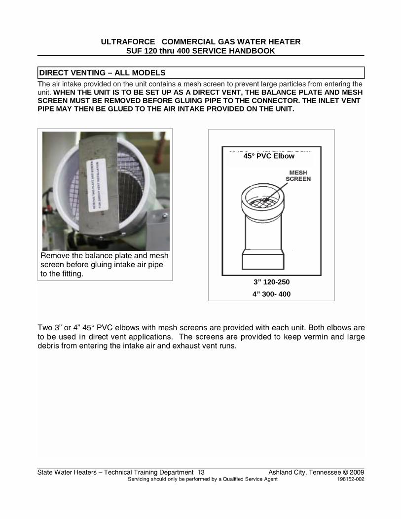
DIRECT VENTING – ALL MODELSThe air intake provided on the unit contains a mesh screen to prevent large particles from entering theunit. WHEN THE UNIT IS TO BE SET UP AS A DIRECT VENT, THE BALANCE PLATE AND MESHSCREEN MUST BE REMOVED BEFORE GLUING PIPE TO THE CONNECTOR. THE INLET VENTPIPE MAY THEN BE GLUED TO THE AIR INTAKE PROVIDED ON THE UNIT.
Remove the balance plate and meshscreen before gluing intake air pipeto the fitting.
3” 120-250
4” 300- 400
45° PVC Elbow
Two 3” or 4” 45° PVC elbows with mesh screens are provided with each unit. Both elbows areto be used in direct vent applications. The screens are provided to keep vermin and largedebris from entering the intake air and exhaust vent runs.

ULTRAFORCE COMMERCIAL GAS WATER HEATERSUF 120 thru 400 SERVICE HANDBOOK
State Water Heaters – Technical Training Department 14 Ashland City, Tennessee © 2009Servicing should only be performed by a Qualified Service Agent 198152-002
CONTROL OVERVIEW – ALL MODELS
Interaction with the water heater controller is donethrough an LCD display called the UniversalInterface Module (UIM).This screen is also referred toas the “desktop” or “desktop menu”. Up and downbuttons and three operation buttons allow navigationthrough the control menus and to make adjustments tothe water heater. Operation of the three lower buttonsis defined immediately above them on the screen.
While the water heater is operating, the user interfacewill display the desktop screen (if there are no activefaults or warnings).
● An example of this screen is shown below. ● The first temperature on this screen is the
temperature of the water inside the tank. ● The second temperature on this screen is the
Operating Set Point. ● The Operating Set Point is the temperature at
which the water heater will maintain the waterinside the tank.
● The third line on the screen is a textdescription of the Operational State of thewater heater. The operating state of the waterheater is also indicated graphically by statusicons.
The table of status icons describes graphicallyoperational details of the water heater. Below is alegend of all the status icons:
StatusIcon
Description
The temperature of the water in the tank hasfallen and the water heater will now initialize anew heating cycle.
The temperature of the water in the tank hasreached the Operating Set Point.
The cont rol i s un able t o i nitiate any f urtherheating cycles. This is usually caused by a faultcondition detected by the control, but can alsooccur when an external system (like an energymanagement sys tem) has as ked t he w aterheater to discontinue any further heat cycles.
The blower is being energized.
The blower pressure switch has been made.
The igniter has been energized.
The igniter has been energized and sufficientcurrent for ignition has been detected.
The control has requested that the gas valvebe turned on.
The control has sensed flame in the burner.
The control has detected a fault condition. Afault condition will cause the water heater todiscontinue operation.
The control has detected a warning condition.These conditions w ill not cause t he waterheater to discontinue further heating cycles, butdoes merit attention.
CONTROL OVERVIEW
^
OPERATION BUTTONS
UP AND DOWN
BUTTONS

ULTRAFORCE COMMERCIAL GAS WATER HEATERSUF 120 thru 400 SERVICE HANDBOOK
State Water Heaters – Technical Training Department 15 Ashland City, Tennessee © 2009Servicing should only be performed by a Qualified Service Agent 198152-002
ADJUSTING TANK TEMPERATURE – OPERATING SET POINT - DIFFERENTIAL
The Operating Set Point of this water heaterdetermines the regulated temperature for the water inthe tank. This parameter is adjusted in the desktopTemperature menu. Items in this menu allow you tomonitor different temperature readings in the tankalong with adjusting the Operating Set Point andDifferential.
ACTION:From the desktop screen, press Menu.DISPLAY:
ACTION:From the Main Menu, press Select to enter the"Temperatures" screen.
DISPLAY:
ACTION:Press Change then use the UP and DOWN buttons tochange the temperature Set Point.
DISPLAY:
Note: This procedure can also be used to change theDifferential. The tank Upper and Lower Temperaturesare not user changeable. They are determined by thetemperature probes on the heater.
ACTION:Press Update to accept the change or Cancel to resetit.
DISPLAY:

ULTRAFORCE COMMERCIAL GAS WATER HEATERSUF 120 thru 400 SERVICE HANDBOOK
State Water Heaters – Technical Training Department 16 Ashland City, Tennessee © 2009Servicing should only be performed by a Qualified Service Agent 198152-002
CHANGING THE DISPLAY UNITS
The desktop menu has the option of selectingbetween degrees Fahrenheit and degrees Celsius fortemperature displays. This can be found in the“Display Settings” menu. Also in this menu, you mayadjust how the back-light operates and the contrast ofthe LCD screen.
ACTION:From the Main Menu, press the DOWN button tohighlight "Display Settings" then press Select.
DISPLAY:
ACTION:Use the UP and DOWN buttons to highlight thedesired setting. Then press Change. Again, use theUP and DOWN buttons to scroll through the optionsfor that setting.
DISPLAY:
ACTION:Press Update to accept the change or Cancel toreject it.
DISPLAY:

ULTRAFORCE COMMERCIAL GAS WATER HEATERSUF 120 thru 400 SERVICE HANDBOOK
State Water Heaters – Technical Training Department 17 Ashland City, Tennessee © 2009Servicing should only be performed by a Qualified Service Agent 198152-002
FAULT AND WARNING CONDITIONS – ADVANCED DIAGNOSTIC INFORMATION
This water heat er control has t he abil ity to monitoralmost all aspects of the water heater's operation. Inthe c ase t hat there i s an undes irable or uns afecondition t hat o ccurs, t he water heat er control willdetect t his c ondition and de termine the appropriateaction. T he w ater heat er c ontrol will di splay t heinformation on the desktop in plain text that accuratelydescribes the condition and diagn ostics i nformationthat can be used to correct the issue.
There are t wo t ypes o f c onditions t hat c an oc curduring operation. These are Warnings and Faults:
Warnings: This is a non-safety related condition thatthe control has det ected t hat m ay cause the waterheater to operate in a less than optimal condition, butdoes not pose a safety concern.
NOTE: When t hese conditions oc cur, continuedheating cycles will continue and the heater will attemptto regulate the water in the tank to the Operating SetPoint.
Example of a Warning:
Faults: This is a safety related condition that has beendetected by the heater.
NOTE: When these conditions occur, the water heaterWILL NOT CONTINUE any further heating cycles andthe water will no longer be heated until the condition iscorrected and, in most cases, power has been cycled.
Example of a Fault:
Advanced Diagnostic InformationWhen a fault or warning has been declared, advancedinformation can be found in the control. By pressingthe A dvanced but ton, det ailed i nformation can befound regarding diagnosing and resolving the problem.
WARNING: Usage of the Advanced informationrequires ability equivalent to that of a licensedtradesmen in the field involved.

ULTRAFORCE COMMERCIAL GAS WATER HEATERSUF 120 thru 400 SERVICE HANDBOOK
State Water Heaters – Technical Training Department 18 Ashland City, Tennessee © 2009Servicing should only be performed by a Qualified Service Agent 198152-002
ACCESS TO THE CURRENT FAULT OR WARNING
When a fault or warning has been detected by thecontrol it will automatically be displayed on the screenand the back light will blink. If you choose to leave thecurrent fault or warning by pressing the Back key, youcan always return to the fault through the displaymenu through the menu.
ACTION:To get to the current fault information screen, pressMenu.
DISPLAY:
ACTION:Press the DOWN button for more information.
DISPLAY:

ULTRAFORCE COMMERCIAL GAS WATER HEATERSUF 120 thru 400 SERVICE HANDBOOK
State Water Heaters – Technical Training Department 19 Ashland City, Tennessee © 2009Servicing should only be performed by a Qualified Service Agent 198152-002
VIEWING THE FAULT HISTORY - VIEWING INFORMATION ABOUT THE HEATER
The controller for this water heater will store a historyof ten of the last Fault and Warning conditions thatoccurred. This is stored in the Fault History. Theinformation about the fault or warning will includediagnostic information as well as an estimate of howlong ago the fault occurred.
ACTION:Press the SELECT button for more information.
DISPLAY:
ACTION:Press the DOWN key to scroll through the faulthistory. If you select a specific fault or warning, youmay press the VIEW button to view details regardingthis fault.
DISPLAY:
Viewing Information About the Water Heater
The control for this water heater monitors manydifferent aspects of the water to ensure safe andoptimal operation. Much of the information monitoredis available to view in two areas of the control. Thefirst is the "Heater Status" and; the second is"Heater Information."
These items can be selected through the desktopmenu. In these menus, detailed information about thewater heater and the current status of specificconditions can be found.

ULTRAFORCE COMMERCIAL GAS WATER HEATERSUF 120 thru 400 SERVICE HANDBOOK
State Water Heaters – Technical Training Department 20 Ashland City, Tennessee © 2009Servicing should only be performed by a Qualified Service Agent 198152-002
CONTROL SEQUENCE (TYPICAL ALL MODELS)
TYPICAL SEQUENCE
1. When the control is powered it should display“waiting for connection” and “UIM v2.06”*. Themanufacturer and unit model will be next. The nextdisplay will include water temperature, temperaturesetting and heater status.* This number may change as software revisions aremade.
2. The control performed selected system diagnosticchecks immediately upon power up. This includesconfirming the proper state of the air/gas switches andECO limit device and powered anodes.
3. If the control determines that the actual watertemperature inside the tank is below the programmedtemperature set-point less the differential, a call forheat is activated.
4. If all checks are successfully passed, thecombustion blower is energized for the pre-purgecycle.
5. When the pre-purge cycle is complete, power isapplied to the igniter element for the igniter warm-upperiod.
6. At the conclusion of the igniter warm-up period, thegas valve will open, allowing gas to enter the burnerchamber.
7. The igniter will remain on for a short predeterminedtime period, then will be turned off.
8. The control will monitor the flame sense probe toconfirm a flame is present. If a flame is not verifiedwithin predetermined time period, the gas valve willimmediately be closed, and the blower will continue torun for approximately 30 seconds inter-purge. Thecontrol will try for ignition two more times beforelockout.
9. If a flame is confirmed, the control will enter theheating mode where it will continue heating the tankwater until the set point temperature plus differential isreached. At this point, the gas valve is closed and thecontrol enters the post-purge cycle.
10. The combustion blower will run for the duration ofthe post purge cycle to purge the system of allcombustion gases. When the post purge cycle iscomplete, the blower is de-energized and will coast toa stop.11. The control will now enter the idle state whilecontinuing to monitor the internal tank watertemperature and the state of other system devices. Ifthe temperature drops below the set-point value lessdifferential, the control will automatically return to step 2 and repeat the entire operating cycle.
Blow er icon indicates
pow er to the blow er
Check mark in the box indicates the blow er
proving sw itch contacts are made
Flame icon indicates burner is ignited and that f lame has been
sensed.

ULTRAFORCE COMMERCIAL GAS WATER HEATERSUF 120 thru 400 SERVICE HANDBOOK
State Water Heaters – Technical Training Department 21 Ashland City, Tennessee © 2009Servicing should only be performed by a Qualified Service Agent 198152-002
CONTROL SEQUENCE FLOW CHART
Power on
Control displays model,
temperature setting and
status
The control performs internalsystem checks and determines
tank temperature is below set point
If checks are not passed the control will
display an error or warning.
If all checks are passed and there is a call for heat the
blower is energized for a pre purge
cycle
The control will store an error
history to show what fault occurred
and the time elapsed since the
fault.
When the pre purge is completepower is applied to
the igniter forWarm-up.
At the conclusion of the igniter
warm up the gas valve will open for
4 seconds.
If the control senses flame the water heater will fire until the set
point is reached.
If the control failsto see flame the
blower will continue to run for a 30 second
Inter purge. There will be 3 trials for ignition
before a fault is declared.
At the conclusionof the inter purge
the igniter willwarm and the gas
valve will open.
At the conclusionof the heating
cycle the blowerwill enter a postpurge cycle andthe control will
enter an idle state.

ULTRAFORCE COMMERCIAL GAS WATER HEATERSUF 120 thru 400 SERVICE HANDBOOK
State Water Heaters – Technical Training Department 22 Ashland City, Tennessee © 2009Servicing should only be performed by a Qualified Service Agent 198152-002
CONTROLS – CENTRAL CONTROL BOARD – CCB
The Central Control Board or CCB is containedin the housing shown below. Access to theboard and the wiring harness plugs can beaccomplished by removing two Phillips screwsholding the cover.
The CCB is controlled by the settings giventhrough the desk top menu (UIM). The CCB alsomonitors all pressure switches, the hot surfaceigniter, tank temperatures, the gas valve, theanodes, and the flame sensor.
The CCB directly controls blower speed on theSUF199 and 250 models and indirectly controlsblower speed on the SUF 400 by means of aVariable Frequency Drive (see page 33).
Note: Improper operation may be the result of aloose connection. Please check all wiringconnections and the power supply to the waterheater.
This view shows the cover removed from theCCB.
This is the back of the UIM.
Remove these screws to release
cover

ULTRAFORCE COMMERCIAL GAS WATER HEATERSUF 120 thru 400 SERVICE HANDBOOK
State Water Heaters – Technical Training Department 23 Ashland City, Tennessee © 2009Servicing should only be performed by a Qualified Service Agent 198152-002
CONTROLS – GAS VALVE SUF 120
CONTROLS – GAS VALVE SUF 150
The gas control valve on the SUF 120 has abuilt i n adj ustable pre ssure regulator. T headjustment screw is accessed by removingthe cap screw m arket regulator i n t heillustration.
Inlet gas pressure may be read at the inletpressure tap only if the manual shut off valve(gas cock) is in the “ON” position. Leavingthe knob in the “OFF” position will not allowthe burner to fi re and will generate a faultcode on th e UIM ( Universal I nterfaceModule).
The gas control valve on the SUF 150 is hasa built in pressure regulator. The regulatormay be adjusted by removing the cap screwmarked “regulator” in the illustration.
Inlet gas pressure may be read at the inletpressure tap only if the manual switch is setthe “ON” position.

ULTRAFORCE COMMERCIAL GAS WATER HEATERSUF 120 thru 400 SERVICE HANDBOOK
State Water Heaters – Technical Training Department 24 Ashland City, Tennessee © 2009Servicing should only be performed by a Qualified Service Agent 198152-002
CONTROLS – GAS VALVE SUF 199 and 250
ADJUSTMENT PROCEDURE:GAS PRESSURE SUF 199 AND 250 MODELS
THE SUF 199 AND 250 MODELSINCORPORATE A NEW GAS CONTROL,WHICH OPERATES AT A MANIFOLDPRESSURE OF 0"W.C. (0 kPa) FOR BOTHNATURAL AND PROPANE GAS. SEE THEGAS PRESSURE CHART ON PAGE 4.THESE MODELS ARE CONFIGUREDPRIOR TO BEING SHIPPED FROM THEFACTORY AND NO ADJUSTMENTS ARENECESSARY PRIOR TO STARTUP. THECONTROLLER MONITORS THE AIR FLOWAND MAKES ADJUSTMENTS TO THE FANSPEED WHICH IN EFFECT CONTROLSTHE AMOUNT OF GAS FLOW.THEREFORE, THE UNIT WILL SELFADJUST TO ACQUIRE THE CORRECTAMOUNT OF INPUT.
Supply gas pressure to the water heater fornatural gas should be between a maximumof 10.5" (2.59kPa for natural gas) W.C.(14.0"/3.45kPa for propane) and a minimumas shown on page 4: that is, for Natural Gas4" (.98kPa) W.C. And 9.0" (1.97kPa) forPropane Gas. The inlet gas pressure mustnot exceed the maximum value.
Once the unit is installed and filled with waterand the in let p ressures c onfirmed, s implyturn the switch "on" and observe operation.Cycle the unit "off" and "on" several times toensure proper operation.
HIGH ALTITUDE INSTALLATION
The SUF 199 and 250 models are suitablefor installation up to 10,100 feet above sealevel with no adjustments.
GAS ORIFICE
The SUF 199 and 250 models do not have anatural gas orifice. A .230” orifice is used onLP gas models.
Gas Control Without Orifice
Natural Gas
Venturi Gasket
w/o orifice
Gas Control with .230” LP Orifice
Venturi Gasket w/ LP Gas Orifice(.230” Brass)
IMPORTANT NOTE
A supply gas pressure regulator(service regulator) must be installed onthe gas supply line within 10' (305 cm)of the unit.

ULTRAFORCE COMMERCIAL GAS WATER HEATERSUF 120 thru 400 SERVICE HANDBOOK
State Water Heaters – Technical Training Department 25 Ashland City, Tennessee © 2009Servicing should only be performed by a Qualified Service Agent 198152-002
CONTROLS – GAS VALVE SUF 199 and 250
Pressure readings may be taken on the gasvalve by connecting to the pressure ports onthe valve. The manifold pressure on thisvalve is 0”w.c. (0kPa) when the water heateris running. Refer to the gas pressure chart onpage 4.
Note: Tubing shown on pressure connectionsis installed for manometer connections. It isnot supplied with the water heater.
Manifold gas
Pressure0” WC(0kPa)
Supply gas
pressure
WARNING: Do not attempt adjustments onthis gas valve unless you have acombustion analyzer. Contact the “helpline” listed on the water heater forassistance.

ULTRAFORCE COMMERCIAL GAS WATER HEATERSUF 120 thru 400 SERVICE HANDBOOK
State Water Heaters – Technical Training Department 26 Ashland City, Tennessee © 2009Servicing should only be performed by a Qualified Service Agent 198152-002
CONTROLS – GAS VALVE , ORIFICE CHART– SUF300,400,
The gas cont rol va lve h as a bu ilt in fieldadjustable pressure regulator. The regulatormay be adjusted by removing the cap screwmarked “regulator”. The adjustment screw isunderneath. The g as val ve for the SUFNatural gas model is shown above. This isa 24V. solenoid operated gas valve.
Refer to the replacement parts information atthe back of this manual for part numbers forNatural and LP gas valves for all SUF 300,400, and models.
ORIFICE CHART – SUF 300,400,
Model 300 400
Natural .27 4” .314”
LP .189” .219”
24V Solenoid
connection
Low Gas PressureSwitch
Manual Gas Control Knob

ULTRAFORCE COMMERCIAL GAS WATER HEATERSUF 120 thru 400 SERVICE HANDBOOK
State Water Heaters – Technical Training Department 27 Ashland City, Tennessee © 2009Servicing should only be performed by a Qualified Service Agent 198152-002
CONTROLS – PRESSURE SWITCHES – ALL MODELS
All SUF models are provided with four pressureswitches. T hese s witches ar e es sential to thesafe an d pr oper op eration o f the uni t. T heswitches are wired to the central control board(CCB) individually an d ea ch i s monitoredindividually. The (CCB) is set up to shut the unitdown whenever there is a failure of any of theswitches and declare a fault for each individualswitch. It is important to understand the purposeof each switch.
BLOWER PROVING SWITCHThe Blower Proving S witch i s pr ovided on t heheater t o v erify that t he f an i s op erating. It i s apositive pressure switch whose electrical contactsare normally open. Th e blower p roving switchelectrical contacts will close on a rise in pressureas the blower increases the pressure in the burner.This switch i s c onnected t o t he b urner t ap b y apiece of Tygon (s oft pl astic) t ubing. This t ubingmust be connected in order for the switch to closethe electrical contacts. The controller requires thatthe electrical contacts on this p ressure switch beopen before it will allow the blower to come on. Thecontrol w ill declare a f ault on the U IM if ei thercondition occurs.
BLOCKED OUTLET PROVING SWITCHThe blocked outlet proving switch electrical contactsare normally closed. The blocked outlet provingswitch el ectrical c ontacts w ill open on a rise inpressure. Check t o see i f t he c ondensate i sallowed to f low freely from the exhaust elbow andfor obstructions in the exhaust venting and exhaustvent t erminal. Also c heck the t hat t he equivalentfeet of vent pipe for the specific model has not beenexceeded. Check the vent length tables on page 9
BLOCKED INLET PROVING SWITCHThe Blocked Inlet Proving switch electrical contactsare normally closed. The bl ocked i nlet pr ovingswitch el ectrical c ontacts w ill op en when anincrease in negative pressure (vacuum) occursin the intake vent pipe. The switch is connected tothe pressure tap on the PVC flange connected tothe inlet of the b lower. When this switch preventsthe u nit f rom ig niting, most li kely the in take isblocked by some means. Verify that the air intakepipe and ai r i ntake v ent t erminal ar e f ree ofobstructions that may prevent air from entering theunit. Also check the that the equivalent feet of ventpipe for the specific model has not been exceeded.Check the vent length tables on page 9
LOW GAS PRESSURE SWITCH
The Low Gas Pressure Switch electrical contactsare normally open. The low gas pressure switchelectrical contacts w ill close on a rise pressure.The c ontacts w ill open w hen t he p ressure fallsbelow the fixed set point. If this happens during aheating cycle a the burner will be shut down and afault will be declared on the UIM.
Low Gas Pressure Sw itch
Pressure Sw itches

ULTRAFORCE COMMERCIAL GAS WATER HEATERSUF 120 thru 400 SERVICE HANDBOOK
State Water Heaters – Technical Training Department 28 Ashland City, Tennessee © 2009Servicing should only be performed by a Qualified Service Agent 198152-002
CONTROLS – PRESSURE SWITCHES – SUF 120 through 250
Note: Check the website www.statewaterheaters.com for Technical Bulletin S023-06 “AirPressure Switches” under “Literature/Service Handbooks”
Top View of Pressure Switches
BLOCKED INLET PRESSURE SWITCH
MODEL PRESSUREAll 0.85”WC
Norm ally Closed / Open on a Rise in
Pressure
Tolerance +/-.05”WC
LOW GAS PRESSURE SWITCH
MODEL PRESSURENatural 4.0”WCLP 8.0”WCNorm ally Open / Close on a Rise in PressureTolerance +/-.05”WC
BLOCKED OUTLET PRESSURE SWITCH
MODEL SWITCH 120N +1.2”WC 150N +0.98”WC 199N +1.06”WC 250N +4.0”WC 120LP +1.3”WC 150LP +1.3”WC 199LP +4.0”WC 250LP +2.0”WC
Norm ally Closed / Open on a Rise in
PressureTolerance +/-.05”WC
BLOWER PROVER PRESSURE SWITCH
MODEL PRESSUREAll +.075”WC
Norm ally Open / Close on a Rise in PressureTolerance +/-.05”WC

ULTRAFORCE COMMERCIAL GAS WATER HEATERSUF 120 thru 400 SERVICE HANDBOOK
State Water Heaters – Technical Training Department 29 Ashland City, Tennessee © 2009Servicing should only be performed by a Qualified Service Agent 198152-002
CONTROLS – PRESSURE SWITCHES – SUF 300,400,
Note: Check the website www.statewaterheaters.com for Technical Bulletin S023-06 “AirPressure Switches” under “Literature/Service Handbooks”
Top View of Pressure Switches
SUF 300,400,
BLOCKED INLET PRESSURE SWITCH
MODEL PRESSURE300 -.085”WC400 -1.25”WC500 -1.35”WC
Norm ally Closed/Open on a Rise in
PressureTolerance +/-.05”WC
LOW GAS PRESSURE SWITCH
MODEL PRESSURENatural +4.6”WCLP +9.0”WC
Norm ally Open/Close on a Rise in
PressureTolerance +/-.05”WC
BLOCKED EXHAUST PRESSURE SWITCH
MODEL PRESSURE300 +1.15”WC400 +1.39”WC500 +1.77”WC
Norm ally Closed / Open on a Rise in
PressureTolerance +/-.05”WC
BLOWER PROVER PRESSURE SWITCH
MODEL PRESSURE300 +1.0”WC400 +2.5”WC500 +4.5 'WC
Norm ally Open / Close on a rise in Pressure
Tolerance +/-.05”WC

ULTRAFORCE COMMERCIAL GAS WATER HEATERSUF 120 thru 400 SERVICE HANDBOOK
State Water Heaters – Technical Training Department 30 Ashland City, Tennessee © 2009Servicing should only be performed by a Qualified Service Agent 198152-002
CONTROLS – CONNECTIONS, IGNITER, FLAME SENSOR, SIGHT GLASS, POWEREDANODES
The connections for the hot surface igniterand the flame sense rod are shown below.Also shown is the burner sight glass. Thesefeatures are typical for all models.
The new U ltra Force com mercial w aterheater i s eq uipped w ith pow ered an odes.These anodes never need replacement. TheCCB monitors the cur rent th rough t heanodes and will declare a fault i f there is adisconnected wire or i f there is no water inthe tank.
Flame Sensor
Hot Surface Igniter
Burner Mounting Bolts
Burner Sight Glass
Powered anode connection

ULTRAFORCE COMMERCIAL GAS WATER HEATERSUF 120 thru 400 SERVICE HANDBOOK
State Water Heaters – Technical Training Department 31 Ashland City, Tennessee © 2009Servicing should only be performed by a Qualified Service Agent 198152-002
HOT SURFACE IGNITER / FLAME SENSOR / CONTROL TIMING
HOT SURFACE IGNITER
This water i s equipped with an electric hotsurface i gniter. The i gniter m aterial i ssilicone carbide and should not be handledwith bare hands because of possible damageto the igniter.
The normal ohm read ing at 77°F is listedbetween 40 and 70 ohms. The minimumigniter current monitored by the CCB is 2.7amps. Once this threshold is met a checkmark will appear by the igniter i con i n theUIM (display).
FLAME SENSOR
This water hea ter is eq uipped w ith anelectronic f lame sensor. The flame sensorsenses fl ame by passi ng a s mall electriccurrent through the burner flame. This typeof f lame s ensing is al so k nown a s fl amerectification. T he CCB is l ooking fo r aminimum current of .7 micro amperes for thewater heater to operate. Once this current isestablished the UIM will display a flame icon.
CONTROL TIMING
Pre-purge 25 seconds
Igniter Warm-up 17 seconds
Trial for ignitionGas Control Open
5 seconds
Inter/Post Purge 30 seconds

ULTRAFORCE COMMERCIAL GAS WATER HEATERSUF 120 thru 400 SERVICE HANDBOOK
State Water Heaters – Technical Training Department 32 Ashland City, Tennessee © 2009Servicing should only be performed by a Qualified Service Agent 198152-002
BLOWER SPEED CONTROL SUF 199 AND 250
The input of the SUF 199 and SUF 250 isdetermined by the blower. The input of thewater heater may be determined by clockingthe meter as shown on page 5 or by makingsure the blower i s receiving the proper Hzsignal. The blower rpm is controlled by theCentral Control Board (CCB). The signal tothe blower may be measured by attaching aMULTIMETER that has a Hertz (Hz) settingas shown in the illustration to the right. If theHz signal is within +/
Model Hz Hz
199 N 133 87
250 N 133 87
199 LP 200 156
250 LP 266 96
Note: R emoving the plug show n in theillustration will cause the blower to accelerateand the input of the water heater to increaseto a much higher rate.
Meter black lead is connected to ground (notshown) and the red lead is connected to anopen te rminal o n bl ower spee d con trolconnection.
Meter red probe connected to
open terminal on plug

RC RA 0V AI1 +5V DO LI1 LI2 LI3 LI4 +15V
ULTRAFORCE COMMERCIAL GAS WATER HEATERSUF 120 thru 400 SERVICE HANDBOOK
State Water Heaters – Technical Training Department 33 Ashland City, Tennessee © 2009Servicing should only be performed by a Qualified Service Agent 198152-002
VARIABLE FREQUENCY DRIVE – SUF 400
VARIABLE FREQUENCY DRIVE
1-10 VDC Speed Instruction Enable Disable Circuit
The Ultra Force SUF 400 model has a variable frequency drive (VFD) that controls therpm of the blower motor. The VFD receives a signal from the central control board thatinstructs the VFD to transmit the proper frequency to the blower to produce the proper blowerspeed and proper input.
Three conditions must be met for the frequency drive to start the blower:
1. 120VAC must be supplied to the VFD 120VAC input.
2. The ignition control board closes an enable circuit – terminals LI1 and +15V
3. The ignition control board sends a 1-10VDC instruction – terminals 0V and AI1. See tableon the next page for voltage and frequency information.
GROUND HOT NEUTRAL
R/L1 NG
BLOWER MOTOR WIRES
BLACK WHITE RED
U/T1 V/T2 W/T3
NOTE: BE SURE TO MATCH WIRECOLORS WHEN CONNECTING BLOWER
WIRES OR BLOWER MAY RUNBACKWARD AND CAUSE A FAULT.
155

ULTRAFORCE COMMERCIAL GAS WATER HEATERSUF 120 thru 400 SERVICE HANDBOOK
State Water Heaters – Technical Training Department 34 Ashland City, Tennessee © 2009Servicing should only be performed by a Qualified Service Agent 198152-002
VARIABLE FREQUENCY DRIVE - BLOWER SPEED AND PRESSURE READINGSThe instructions for the VFD are sent from the CCB to in the form of a DC current. The chartbelow lists the current readings, the frequency signal displayed by the VFD, and the pressureswitch settings needed for the CCB to let the burner operate. The frequency numbersdisplayed may vary slightly with slight variations in the DC voltage generated by the CCB. Ifthe water heater exhibits poor run characteristics check the frequency display. If thefrequency is more than 5% out of range, check the DC volt signal at the terminals shown onpage 33.
Voltage – Frequency – Speed Instructions - VFD
Model SUF400
Instruction Volts DCTerminals 0V and AI1
0 – 10VDC
Volts Frequency PressureW.C.”
Ignition (low speed) 7.53 150 Hz+/- 2 5.3”
Purge (high speed) 7.77 155 Hz+/- 2 5.85”
VFD Part Number 197500-000
Frequency is displayed in the red LED. 155Hz
155

ULTRAFORCE COMMERCIAL GAS WATER HEATERSUF 120 thru 400 SERVICE HANDBOOK
State Water Heaters – Technical Training Department 35 Ashland City, Tennessee © 2009Servicing should only be performed by a Qualified Service Agent 198152-002
WIRING DIAGRAM – SUF 120 – 300

ULTRAFORCE COMMERCIAL GAS WATER HEATERSUF 120 thru 400 SERVICE HANDBOOK
State Water Heaters – Technical Training Department 36 Ashland City, Tennessee © 2009Servicing should only be performed by a Qualified Service Agent 198152-002
WIRING DIAGRAM – SUF 400,

2
500 Tennessee Waltz ParkwayAshland City, TN 37015
www.statewaterheaters.com