sequential synchronous circuit analysisvision.unipv.it/reti-logiche/chap_05_p1...
TRANSCRIPT
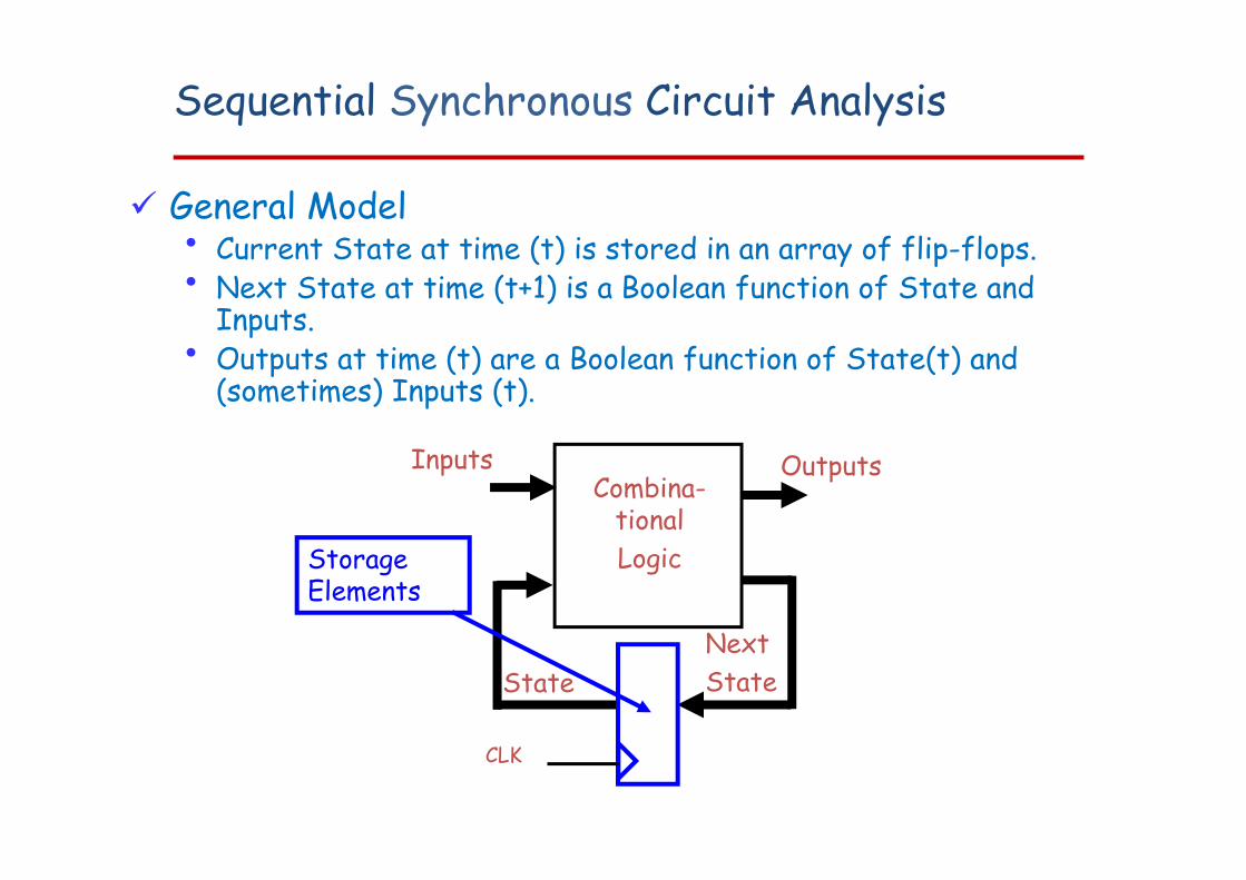
Sequential Synchronous Circuit Analysis
General Model• Current State at time (t) is stored in an array of flip-flops.• Next State at time (t+1) is a Boolean function of State and
Inputs.• Outputs at time (t) are a Boolean function of State(t) and
(sometimes) Inputs (t).
Combina-tionalLogic
Inputs
StateNextState
Outputs
Storage Elements
CLK
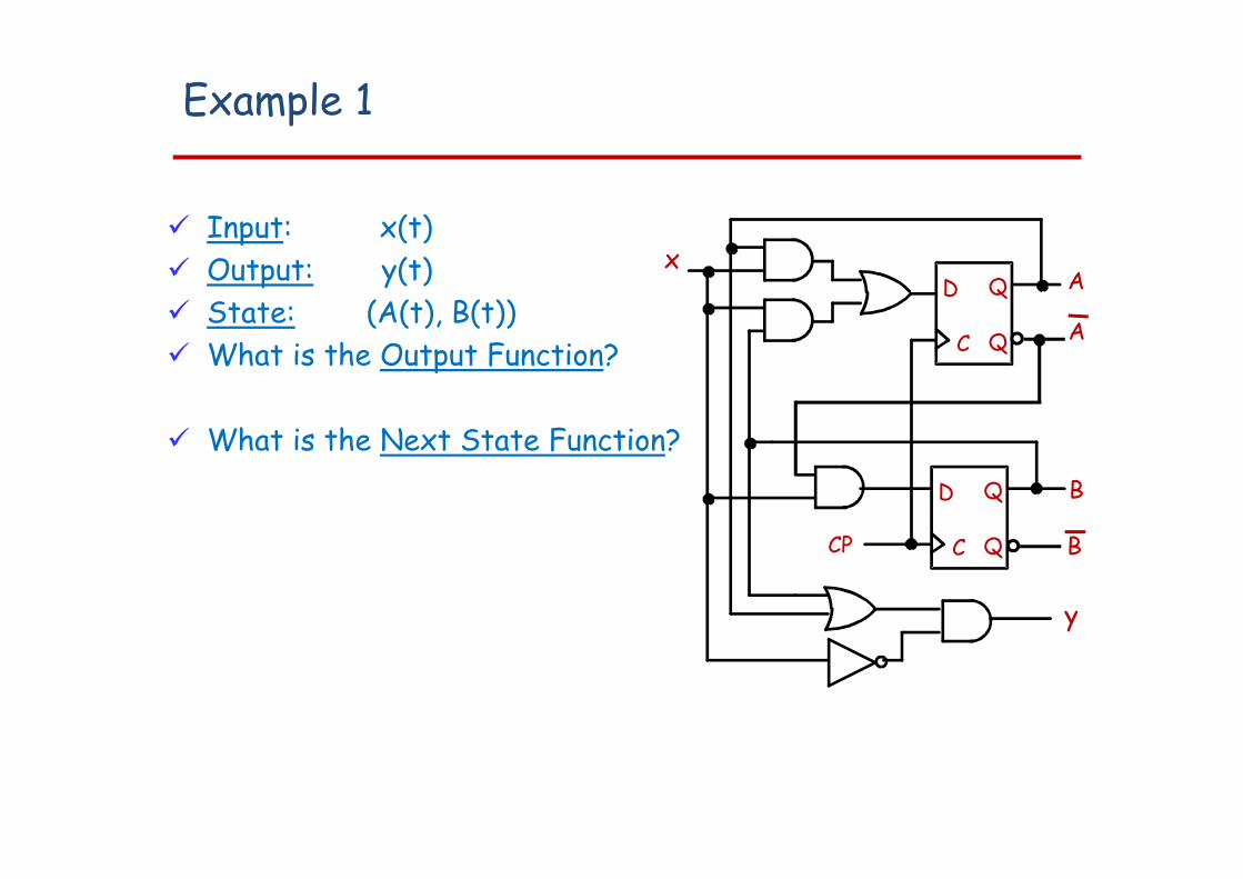
Example 1
Input: x(t) Output: y(t) State: (A(t), B(t)) What is the Output Function?
What is the Next State Function?
AC
D Q
Q
C
D Q
Q
y
xA
B
CP B
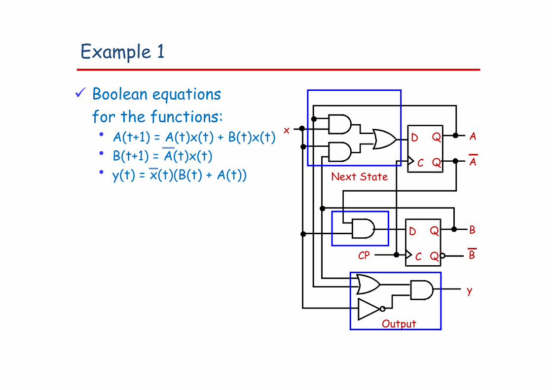
Example 1
Boolean equations for the functions:• A(t+1) = A(t)x(t) + B(t)x(t)• B(t+1) = A(t)x(t)• y(t) = x(t)(B(t) + A(t))
C
D Q
Q
C
D Q
Q'
y
x A
A
B
CP
Next State
Output
B
State Table Characteristics
State table – a multiple variable table with the following four sections:• Present State – the values of the state variables for
each allowed state.• Input – the input combinations allowed.• Next-state – the value of the state at time (t+1) based
on the present state and the input.• Output – the value of the output as a function of the
present state and (sometimes) the input. From the viewpoint of a truth table:
• the inputs are Input, Present State• and the outputs are Output, Next State
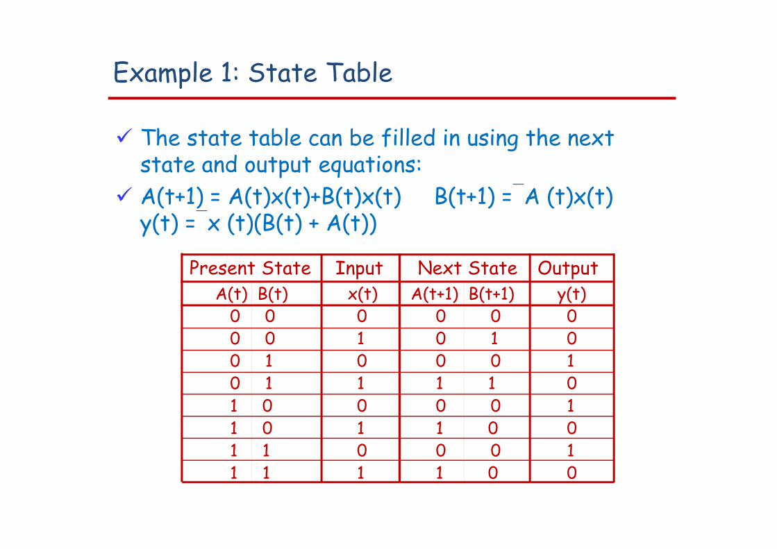
Example 1: State Table
The state table can be filled in using the next state and output equations:
A(t+1) = A(t)x(t)+B(t)x(t) B(t+1) =A (t)x(t) y(t) =x (t)(B(t) + A(t))
Present State Input Next State OutputA(t) B(t) x(t) A(t+1) B(t+1) y(t)
0 0 0 0 0 00 0 1 0 1 00 1 0 0 0 10 1 1 1 1 01 0 0 0 0 11 0 1 1 0 01 1 0 0 0 11 1 1 1 0 0
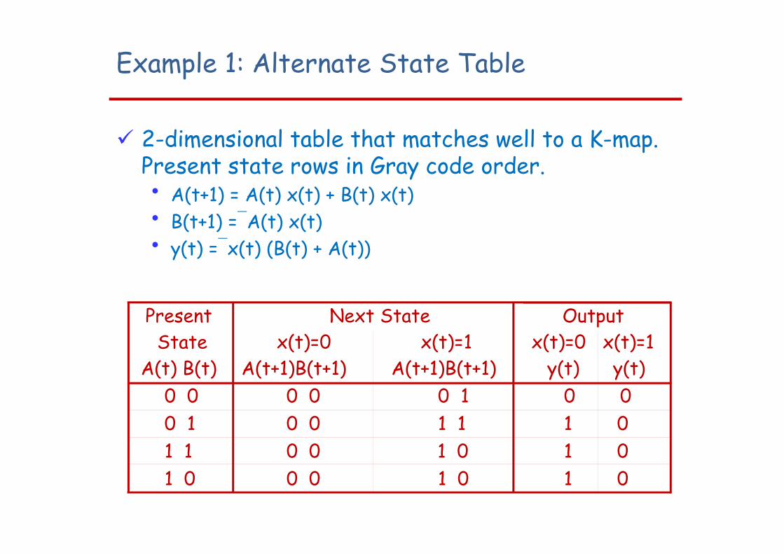
Example 1: Alternate State Table
2-dimensional table that matches well to a K-map. Present state rows in Gray code order. • A(t+1) = A(t) x(t) + B(t) x(t)• B(t+1) =A(t) x(t)• y(t) =x(t) (B(t) + A(t))
Present State
Next Statex(t)=0 x(t)=1
Outputx(t)=0 x(t)=1
A(t) B(t) A(t+1)B(t+1) A(t+1)B(t+1) y(t) y(t)0 0 0 0 0 1 0 00 1 0 0 1 1 1 01 1 0 0 1 0 1 01 0 0 0 1 0 1 0
State Diagrams
The sequential circuit function can be represented in graphical form as a state diagram with the following components:• A circle with the state name in it for each state• A directed arc from the Present State to the Next
State for each state transition• A label on each directed arc with the Input values which
causes the state transition, and• A label:
On each circle with the output value produced, or On each directed arc with the output value produced.
State Diagrams
Label form:• On circle with output included:
state/output Moore type output depends only on state
• On directed arc with the output included: input/output Mealy type output depends on state and input
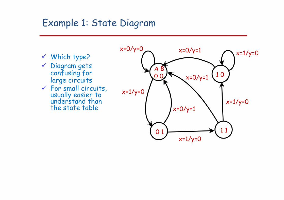
Example 1: State Diagram
Which type? Diagram gets
confusing forlarge circuits
For small circuits,usually easier tounderstand thanthe state table
A B0 0
0 1 1 1
1 0
x=0/y=1 x=1/y=0
x=1/y=0x=1/y=0
x=0/y=1
x=0/y=1
x=1/y=0
x=0/y=0
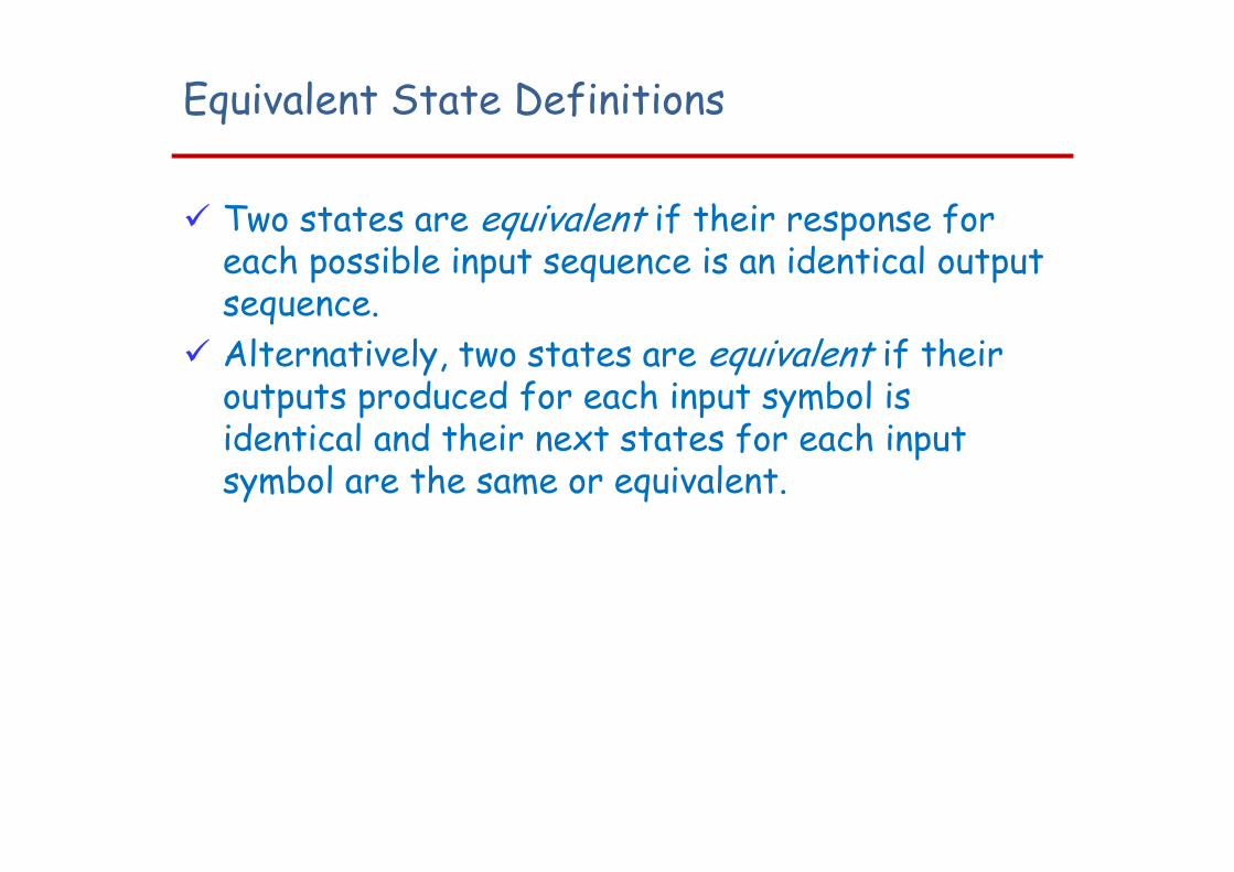
Equivalent State Definitions
Two states are equivalent if their response for each possible input sequence is an identical output sequence.
Alternatively, two states are equivalent if their outputs produced for each input symbol is identical and their next states for each input symbol are the same or equivalent.
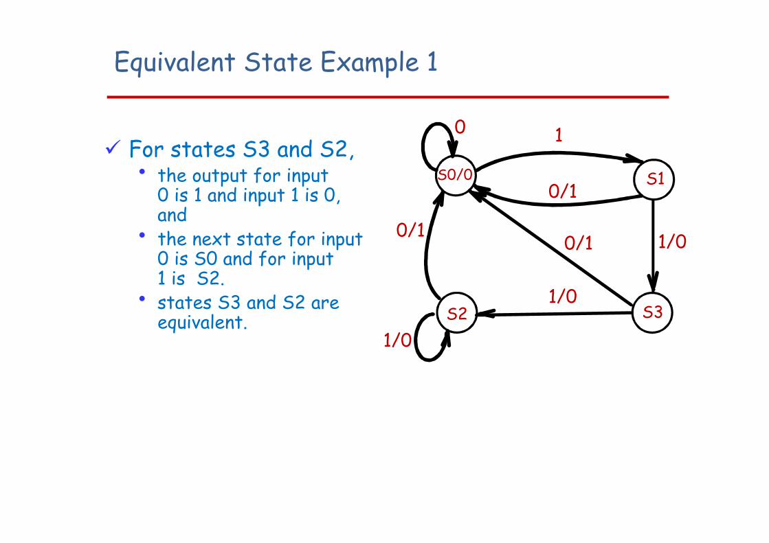
Equivalent State Example 1
For states S3 and S2,• the output for input
0 is 1 and input 1 is 0,and
• the next state for input0 is S0 and for input1 is S2.
• states S3 and S2 are equivalent. S2 S3
1/00/1
1/0
0
S0/0 S1
1/0
0/1
1
0/1
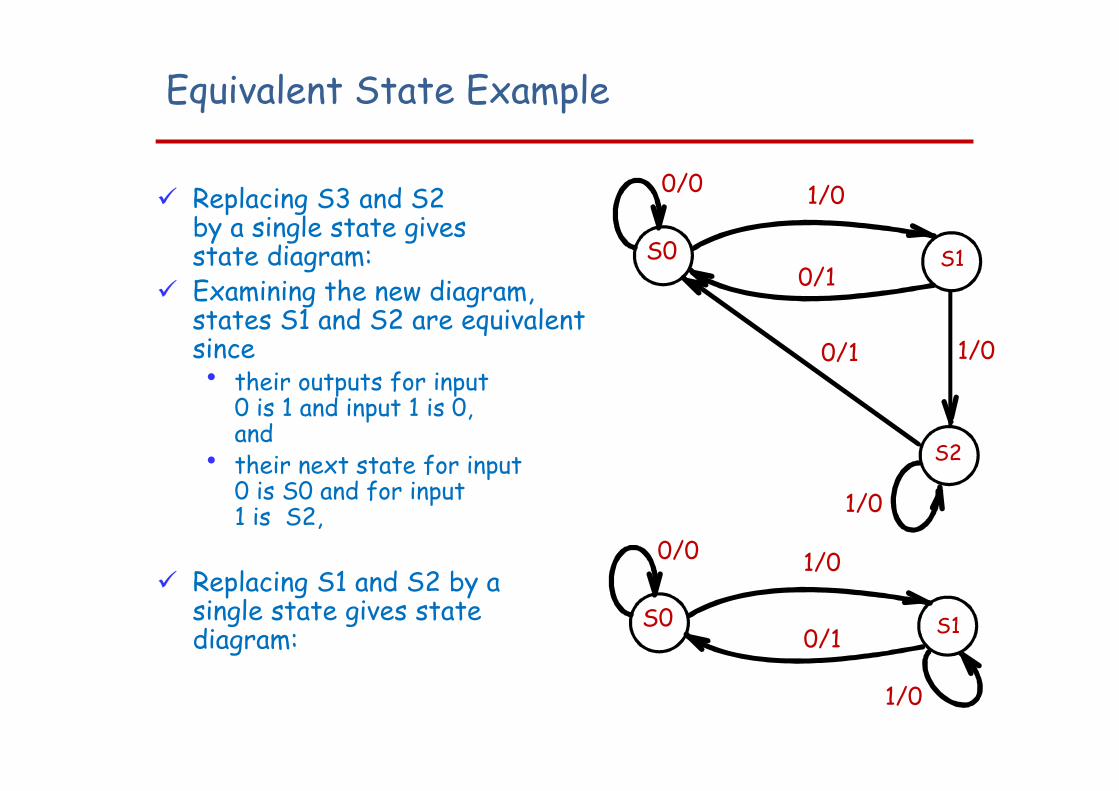
Equivalent State Example
Replacing S3 and S2by a single state givesstate diagram:
Examining the new diagram,states S1 and S2 are equivalent since• their outputs for input
0 is 1 and input 1 is 0,and
• their next state for input0 is S0 and for input1 is S2,
Replacing S1 and S2 by asingle state gives statediagram:
S2
1/0
0/0
S0 S1
1/0
0/1
1/0
0/1
0/0
S0 S1
1/0
0/1
1/0
Moore and Mealy Models
Sequential Circuits or Sequential Machines are also called Finite State Machines (FSMs). Two formal models exist:
Moore Model• Named after E.F. Moore • Outputs are a function
ONLY of states• Usually specified on the
states.
Mealy Model• Named after G. Mealy• Outputs are a function
of inputs AND states• Usually specified on the
state transition arcs.
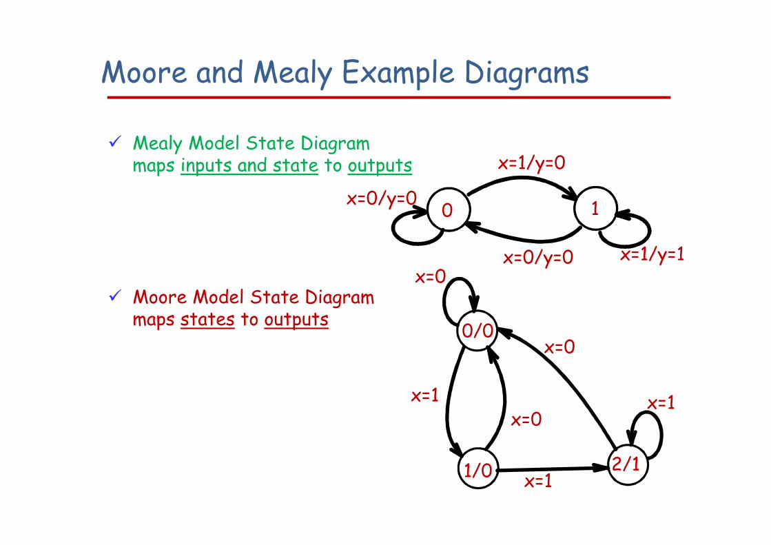
Moore and Mealy Example Diagrams
Mealy Model State Diagrammaps inputs and state to outputs
Moore Model State Diagram maps states to outputs
0 1
x=1/y=1
x=1/y=0
x=0/y=0
x=0/y=0
1/0 2/1
x=1x=1
x=0
x=0
x=1
x=0
0/0
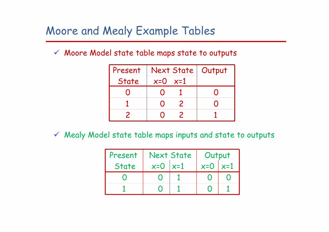
Moore and Mealy Example Tables
Moore Model state table maps state to outputs
Mealy Model state table maps inputs and state to outputs
Present State
Next Statex=0 x=1
Output
0 0 1 01 0 2 02 0 2 1
Present State
Next Statex=0 x=1
Outputx=0 x=1
0 0 1 0 01 0 1 0 1
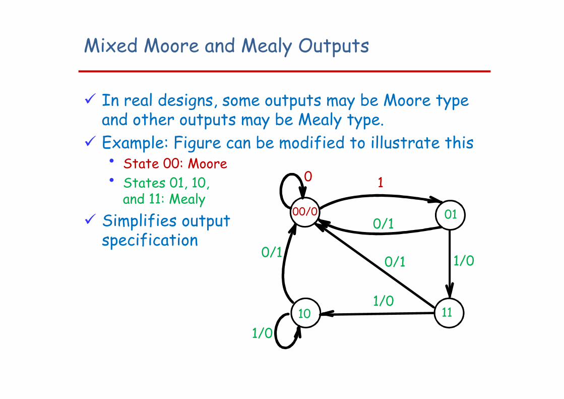
Mixed Moore and Mealy Outputs
In real designs, some outputs may be Moore type and other outputs may be Mealy type.
Example: Figure can be modified to illustrate this• State 00: Moore• States 01, 10,
and 11: Mealy Simplifies output
specification
10 11
1/00/1
1/0
0
00/0 01
1/0
0/1
1
0/1
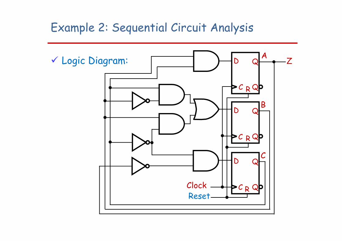
Example 2: Sequential Circuit Analysis
Logic Diagram:
ClockReset
D
QC
Q
R
D
QC
Q
R
D
QC
Q
R
A
B
C
Z
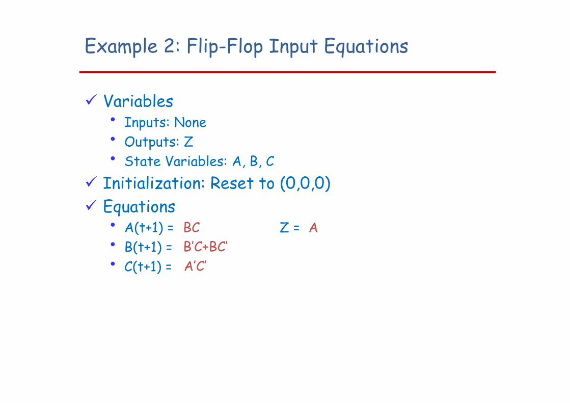
Example 2: Flip-Flop Input Equations
Variables• Inputs: None• Outputs: Z• State Variables: A, B, C
Initialization: Reset to (0,0,0) Equations
• A(t+1) = Z = • B(t+1) = • C(t+1) =
BCB’C+BC’A’C’
A
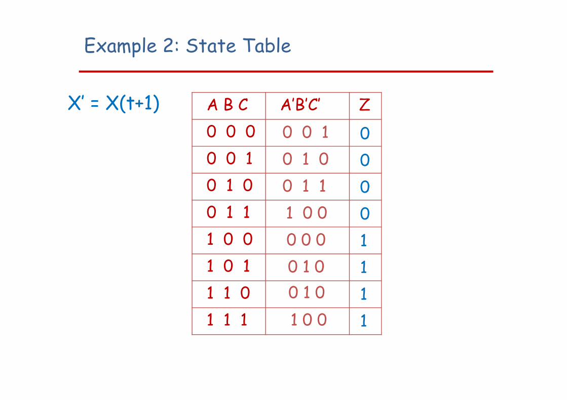
Example 2: State Table
A B C A’B’C’ Z0 0 00 0 10 1 00 1 11 0 01 0 11 1 01 1 1
X’ = X(t+1)0 0 10 1 00 1 11 0 00 0 00 1 00 1 01 0 0
00001111
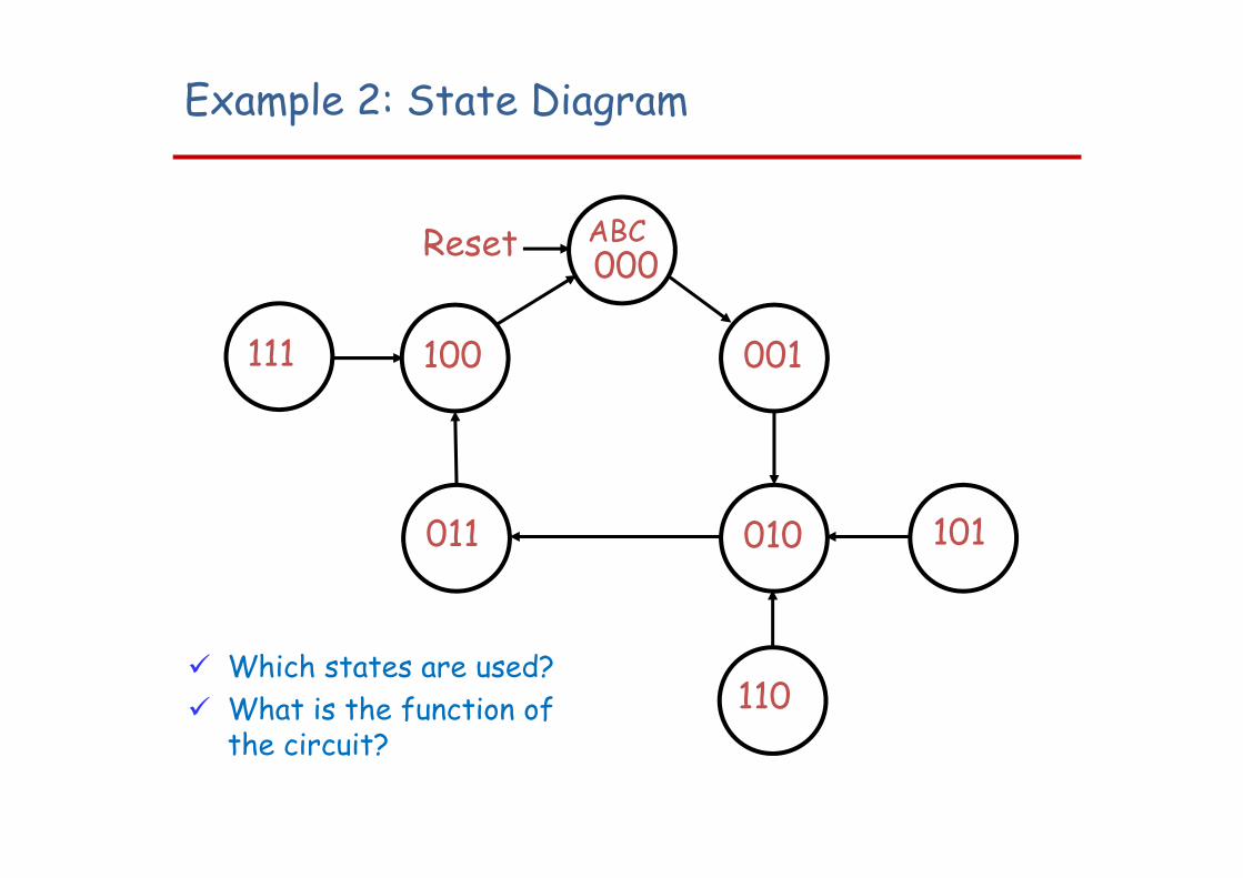
Which states are used? What is the function of
the circuit?
000
011 010
001100
101
110
111
Reset ABC
Example 2: State Diagram
Sequential Asynchronous Circuit Analysis
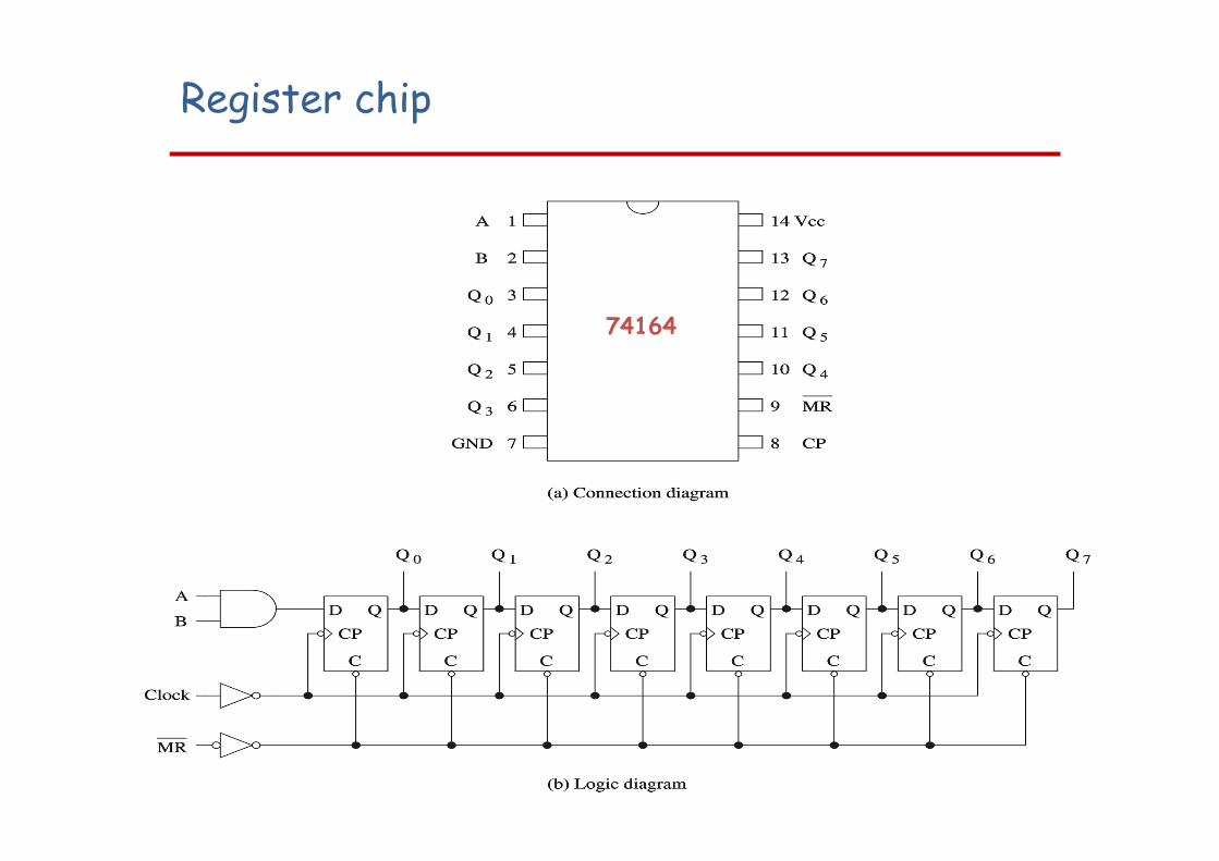
Register chip
74164
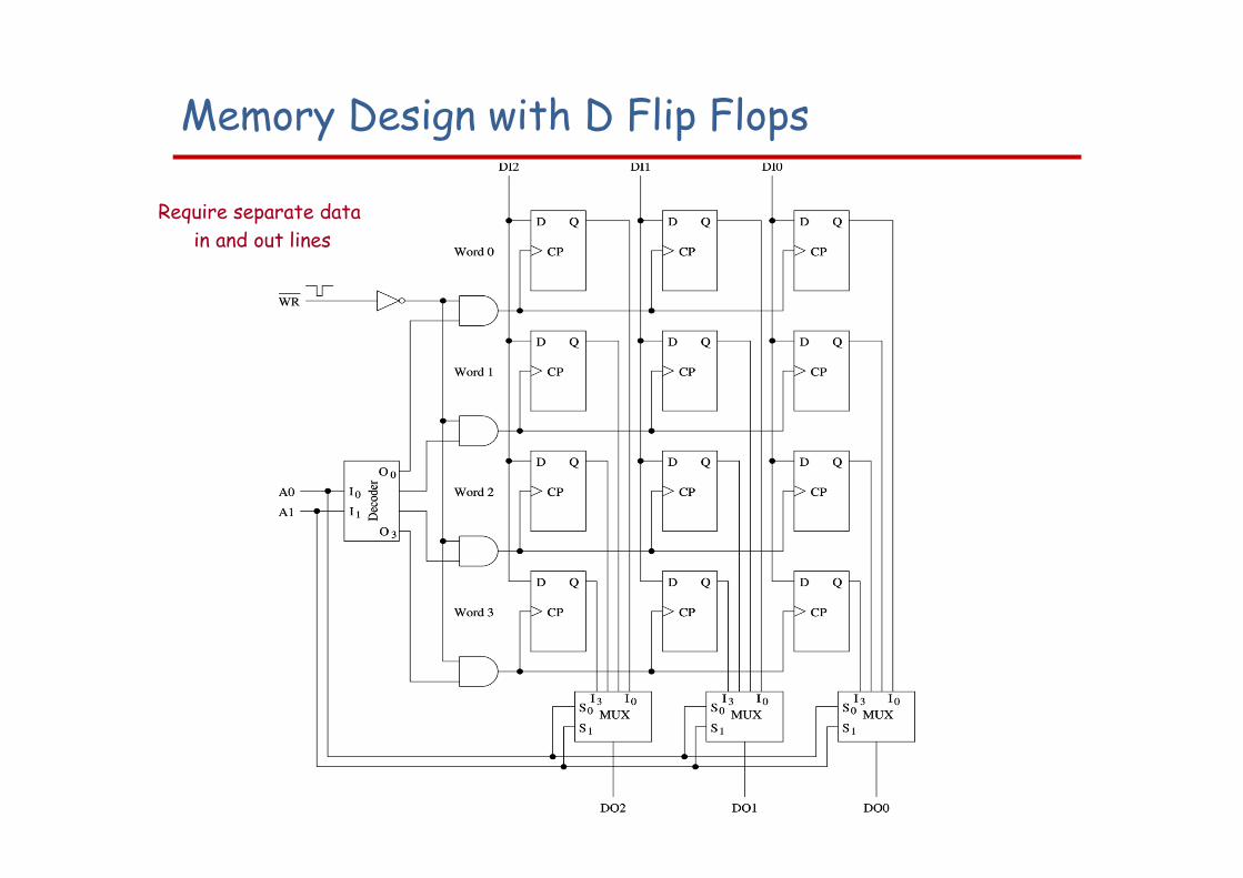
Memory Design with D Flip Flops
Require separate data in and out lines