separation of coherent and incoherent nonlinearities in a heterodyne pump-probe experiment
TRANSCRIPT
Separation of coherent and incoherent
nonlinearities in a heterodyne pump–probe
experiment
P. Borri1,2, F. Romstad1, W. Langbein2, A. E. Kelly3, J.Mørk1, and J. M. Hvam1
1 Research Center COM, The Technical University of Denmark,Building 349, DK–2800 Kgs. Lyngby, Denmark
2 Lehrstuhl fur Experimentelle Physik EIIb, Universitat Dortmund,Otto-Hahn Str.4, 44227 Dortmund, Germany
3 Corning Research Centre, Adastral Park Martlesham Heath IpswichIP5 3RE UK, United Kingdom
Abstract: We demonstrate that the transient coherent nonlinearity(coherent artifact) affecting the pump-probe response of semiconductoroptical amplifiers can be experimentally separated from the incoherenttransient. The technique is based on measuring the mirror componentof the coherent artifact which is a background-free four–wave mixingsignal at a different frequency with respect to the transmitted probe ina heterodyne detection scheme. Measurements on amplifiers of differentlength reveal strong deviations from the commonly expected symmetricshape of the coherent artifact in case of long waveguides.c© 2000 Optical Society of AmericaOCIS codes: (320.0320) Ultrafast optics-(230.5590) Quantum-well devices
References and links1. Z. Vardeny and J. Tauc, “Picosecond Coherence Coupling in the Pump and Probe Technique,”
Optics Comm. 39, 396–400 (1981).2. S. L. Palfrey and T. F. Heinz, “Coherent Interactions in Pump-Probe Absorption Measurements:
The Effect of Phase Gratings,” J. Opt. Soc. Am. B 2, 674–679 (1985).3. K. L. Hall, G. Lenz, E. P. Ippen, and G. Raybon, “Heterodyne Pump–Probe Technique for Time
Domain Studies of Optical Nonlinearities in Waveguides,” Optics Letters 17, 874–876 (1992).4. A. Mecozzi and J. Mørk, “Theory of Heterodyne Pump–Probe Experiments with Femtosecond
Pulses,” J. Opt. Soc. Am. B 13, 2437–2452 (1996).5. K. L. Hall, G. Lenz, A. M. Darwish, and E. P. Ippen, “Subpicosecond Gain and Index Nonlinear-
ities in InGaAsP Diode Lasers,” Optics Commun. 111, 589–612 (1994).6. C. F. Klingshirn, Semiconductor Optics (Springer-Verlag, Berlin, Germany, 1995).7. M. Hofmann, S. D. Brorson, J. Mørk, and A. Mecozzi, ”Time resolved four-wave mixing technique
to meaure the ultrafast coherent dynamics in semiconductor optical amplifiers”, Appl. Phys. Lett.68, 3236-3238 (1996).
8. P. Borri, W. Langbein, J. Mørk, and J. M. Hvam, “Heterodyne Pump–Probe and Four–WaveMixing in Semiconductor Optical Amplifiers Using Balanced Lock–in Detection,” Optics Comm.169, 317–324 (1999).
9. P. Borri, S. Scaffetti, J. Mørk, W. Langbein, J. M. Hvam, A. Mecozzi, and F. Martelli, “Measure-ment and Calculation of the Critical Pulsewidth for Gain Saturation in Semiconductor OpticalAmplifiers,” Optics Commun. 164, 51 (1999).
It has been recognized already for some time that in a pump–probe experiment, coher-ent interactions between the pump and probe pulses affect the probe transmission forsmall pump-probe relative delay times. For the geometry where pump and probe cross
#23078 - $15.00 US Received April 20, 2000; Revised July 17, 2000
(C) 2000 OSA 31 July 2000 / Vol. 7, No. 3 / OPTICS EXPRESS 107

�1, k1
�2, k2
2k2-k1, 2�2-�1(-1 diffraction order of k2)
k2, �2 and -1 diff. order of k1
k1, �1 and +1 diff. order of k2
2k1-k2, 2�1-�2(+1 diffraction order of k1)
isolated coherent artefact
coherent artefact
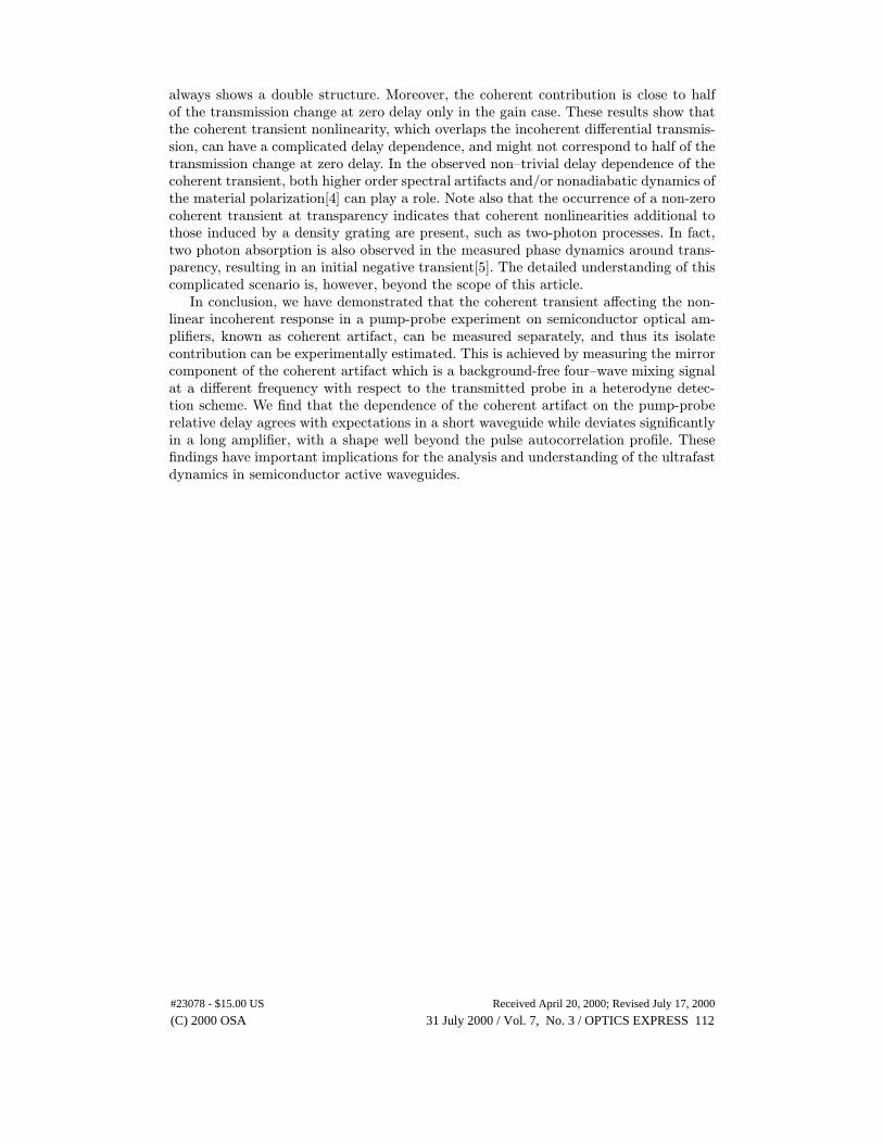
Fig. 1. Scheme of a diffraction geometry experiment in the spatial selection geome-try. Along the probe direction k2 the first diffracted order of the pump is also present(coherent artifact). The diffracted mirror component is along the background-freedirection 2k1 − k2.
at an angle, the so–called coherent artifact is described as the pump radiation whichis scattered into the probe beam by the spatial grating induced in the medium fromthe interference of the coherent pump–probe pulses[1, 2]. In the case of co–polarizedtransform–limited pump-probe beams, the effect of the coherent artifact on the probetransmission is estimated to be a symmetric function of the delay between the twopulses and equal in magnitude to the incoherent contribution at zero delay. Moreover, itis proportional to the pulse intensity autocorrelation if the third-order susceptibility is astep function in time [1, 2]. For non–transform limited pulses, the presence in the coher-ent artifact of an asymmetric contribution related to the real part of the susceptibility,i.e. to a refractive index grating, was also discussed[2]. Recently, a new pump-probetechnique where both beams are co-polarized and co-parallel was demonstrated usinga heterodyne detection scheme, suitable for experiments in active waveguides such assemiconductor optical amplifiers (SOAs) [3]. A theoretical treatment of the coherent ar-tifact in this geometry was given in [4]. There, the role of the gain dispersion of the activemedium (spectral artifact) on the coherent artifact was also evaluated. If the spectralgain slope is small, or the waveguide is very short, the general results mentioned aboveare recovered. A finite gain slope is shown to alter the shape of the coherent artifactfrom a symmetric signal with respect to the delay time into an asymmetric shape forthe separate gain and refractive index changes[4].
Experimentally, the coherent and incoherent part in the change of the probe trans-mission are overlapped, which makes it difficult to extract information on the intrinsicdynamics of the investigated material at early times from a co-polarized pump–probeexperiment. In order to separate the coherent from the incoherent contributions, com-parison between co–polarized and cross–polarized experiment is often used, under theassumption that the interference effects vanish for cross-polarized beams[1]. Alterna-tively, the simple procedure that the coherent artifact is half of the incoherent signaland proportional to the intensity autocorrelation was used to correct the results from apump-probe experiment[5]. In this article we propose a method to directly measure thecoherent signal separately from the incoherent part. We present results that quantifythe magnitude of the coherent artifact in two amplifiers of different length.
Let us first recall the different diffracted nonlinear signals in a grating–induced ex-periment in the usual transmission geometry where pump and probe cross at an an-gle (spatial–selection geometry)[6]. This is depicted in Fig. 1. The pump (probe) beamhas the direction given by the wavevector k1 (k2), and the optical frequency ω1 (ω2).Along the zero order direction (i.e. the direct transmission) of the probe beam the firstdiffracted order of pump beam in the pump-probe induced grating is also present, de-generate with the probe frequency. This is the coherent artifact. The mirror component
#23078 - $15.00 US Received April 20, 2000; Revised July 17, 2000
(C) 2000 OSA 31 July 2000 / Vol. 7, No. 3 / OPTICS EXPRESS 108
-0.5 0.0 0.5 1.0 1.5-0.4
-0.2
0.0FWM(2�
1-�
2)
delay time (ps)
�T
/T
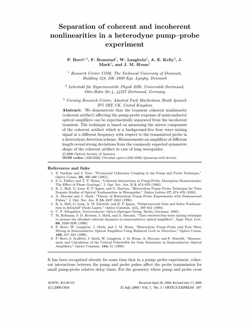
Fig. 2. Measured differential transmission (dotted) and coherent artifact (solid) ina 100µm-long SOA in the gain region.
of this diffraction, with respect to the zero–order transmitted pump, is along the di-rection 2k1 − k2 and has the frequency 2ω1 − ω2. Therefore, the coherent artifact canbe measured separately from the transmitted probe, by detecting its mirror componentwhich is at a different direction and frequency. The third-order coherent interactiongiving rise to these diffracted signals is also called four-wave mixing (FWM)[6].
In a heterodyne detection scheme, pump and probe are co–propagating along thewaveguide, and are distinguished by a small shift of the optical frequencies in a quasi–degenerate scheme[3]. Typically, acousto–optic modulators are used to provide a fre-quency shift in the radio frequency domain. The analogy of this scheme with the spatialselection geometry has been extensively discussed[4]. In this case the interference ofpump and probe gives rise to a modulation of the gain and refractive index of the mate-rial in time rather than in space. This generates frequency sidebands to the pump andprobe signals, in analogy with the different diffraction directions in Fig. 1. The sidebandto the pump frequency which is degenerate with the probe signal is the coherent artifactand its mirror sideband can be detected background-free at a different frequency[4]. Itwas already pointed out experimentally[7, 8] how the heterodyne technique can be usedto measure background-free four-wave mixing signals in SOAs. However, the coherentartifact was not addressed in these experiments.
In this work, we have used a heterodyne detection scheme to perform a pump-probeexperiment on an InGaAs/InGaAsP multiple-quantum-well semiconductor optical am-plifier operating at 1.5µm at room temperature. Pump and probe were co-polarizedin the TE mode of the waveguide. The laser source was the idler of an optical para-metric amplifier providing ∼ 150 fs pulses at 300 kHz repetition rate. We have recentlydemonstrated the feasibility of a heterodyne setup with a low–repetition laser source ofhigh amplitude noise[8]. The pump and probe pulses were nearly transform–limited, bycompensating their linear chirp with the use of a pulse shaper[9]. Using cross-correlatedfrequency resolved optical gating we inferred Gaussian pulse shapes with a bandwidthproduct of 0.44. In our detection scheme the signal is measured by a lock-in referencedby an electrical mixing of the laser repetition rate and the acousto-optic modulator fre-quencies used in the setup[8]. We can easily switch between detecting the transmittedprobe or the FWM signal at 2ω1 − ω2 by adjusting only the lock-in reference whilekeeping the experimental conditions unchanged.
In Fig. 2 the differential transmission is shown (dotted line) as a function of the pump-probe delay time on a 100µm-long device. The pump pulse leads the probe at positivedelays. At the used bias current of 35mA a small signal gain of 6 dB was measured.The center optical frequency of the laser pulses was at 1.52µm, close to the maximumof the amplified spontaneous emission spectrum. The pump energy per pulse at theinput of the device was 0.26pJ. The dynamics of the differential transmission shows an
#23078 - $15.00 US Received April 20, 2000; Revised July 17, 2000
(C) 2000 OSA 31 July 2000 / Vol. 7, No. 3 / OPTICS EXPRESS 109
1500 1550 1600
-5
-4
-3
-2
-1
0
1
30 32 34
-0.4
0.0
0.4
-1 0 1 2 3 4 5
-15
0
15
30
45
28 30 32 34 36
-0.15
0.00
0.15
laser
45mA
AS
E (
a.u.
)
wavelength (nm)
�G
(dB
)
�G
(dB
)
I(mA)
��(d
eg)
delay(ps)
��(r
ad
)
I(mA)
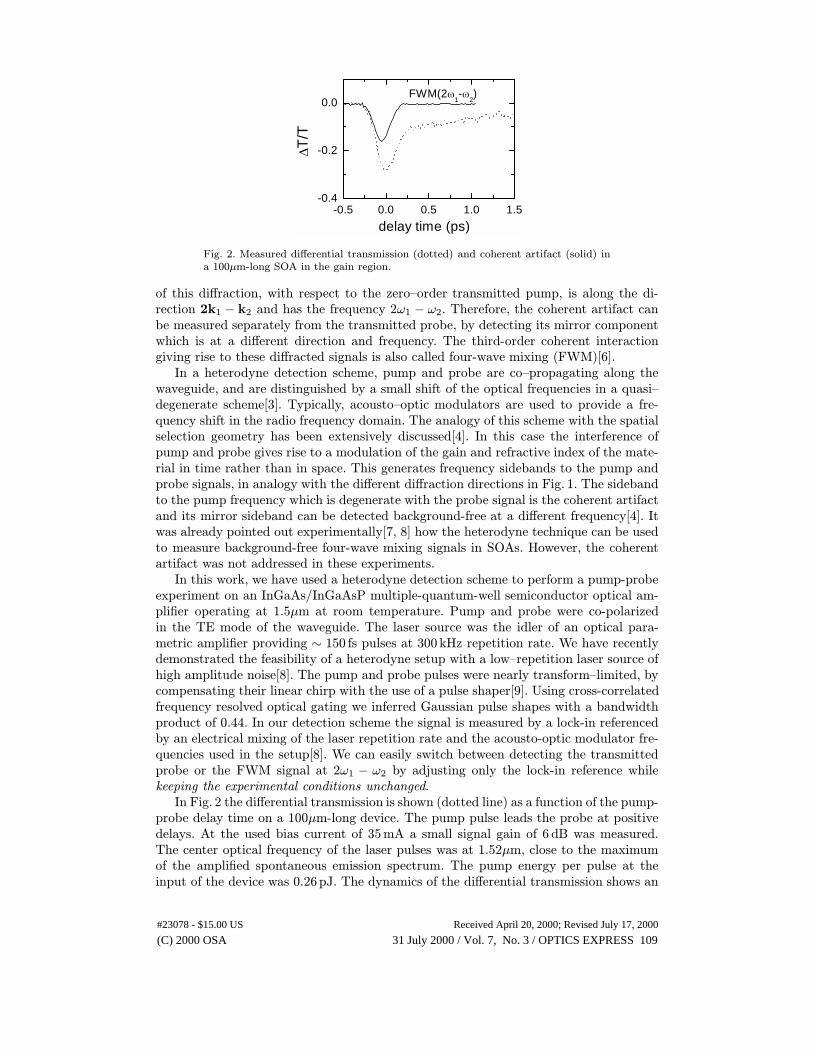
Fig. 3. Upper: amplified spontaneous emission in a 1mm-long SOA and pulse laserspectrum used. Lower: Gain changes (in dB) and probe phase changes versus thepump-probe delay, at different bias currents around transperency. In the inset, thevalues of the long-lived leftovers versus the bias current are shown. The valueschange sign, going from absorption to gain of the device, and cross zero at trans-parency.
initial negative transient with an ultrafast recovery comparable to the pulse duration,and a slower recovery over several hundred of femtoseconds. The ultrafast transient isusually attributed to spectral hole–burning, and the slower transient to carrier heatingdynamics in SOAs[5]. In general, the occurrence of the coherent artifact, that overlapsthe initial transient, makes it difficult to quantitatively estimate the spectral hole–burning component. For a grating formed by a modulation of the absorption coefficient,i.e., related to the imaginary part of the susceptibility, the scattered pump radiationis in phase with the transmitted probe. Thus, the amplitude of the FWM signal at2ω1−ω2 fully quantifies the coherent artifact, if the scattered pump from the refractiveindex grating is negligible[2]. The solid line in Fig. 2 is the measured FWM signal at2ω1 − ω2 divided by the probe transmission signal without the pump, plotted as anegative transient. This is the measured contribution to the differential transmissiongiven by the coherent artifact. This contribution is half of the transmission change atzero delay, and has a delay dependence like the pulse autocorrelation with a slight shiftto negative delay, similar to expectations[4].
#23078 - $15.00 US Received April 20, 2000; Revised July 17, 2000
(C) 2000 OSA 31 July 2000 / Vol. 7, No. 3 / OPTICS EXPRESS 110

-0.30
-0.15
0.00
-0.30
-0.15
0.00
-1.0 -0.5 0.0 0.5 1.0
-0.30
-0.15
0.00
FWM(2�1-�
2)
I=34mA (2.48dB)
�T
/T
I=32mA (0dB)
I=30mA(-2.43dB)
delay(ps)
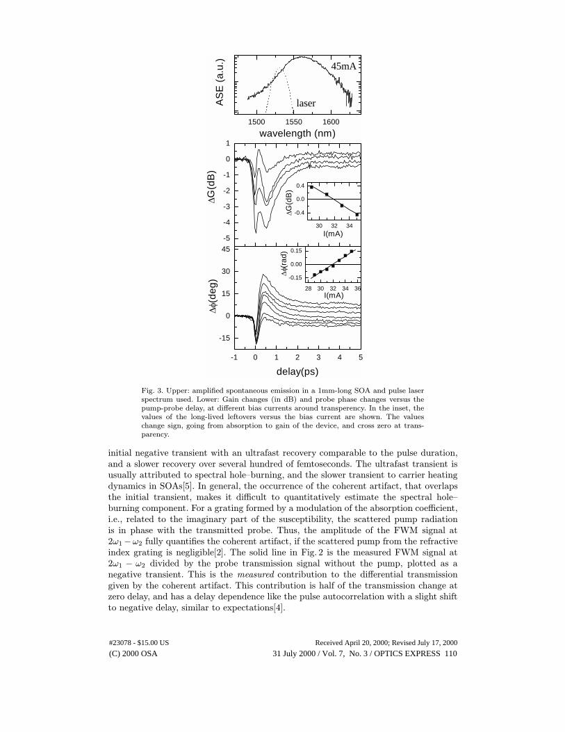
Fig. 4. Differential transmission (dotted) and coherent artifact (solid) in a 1mm-long SOA at different bias currents as indicated. The small signal gain (excludinginternal waveguide losses) is also indicated.
In order to further explore the role of the coherent artifact in a pump-probe exper-iment, and its interplay with spectral artifacts, similar measurements were performedon a multiple quantum well SOA of 1mm length, around the transparency current. Inthis case the spectrum of laser pulses probes a high gain slope, as shown in the toppart of Fig. 3 were the laser spectrum is shown together with the amplified spontaneousemission from the device. The measured differential transmission around transparencycurrent is shown in the lower part of Fig. 3. Due to the high propagation losses fromthe long waveguide, a high input pump energy (∼ 4 pJ) was necessary to achieve anoutput signal with good signal-to-noise ratio. Both amplitude and phase changes of thetransmitted probe are shown, corresponding to gain and refractive index changes[5]. Inparticular, the gain in dB deduced from the transmission change is indicated[8]. Thelong-lived leftovers of both gain and phase changes show the transition from absorptionto gain of the device by changing their sign[5] (see insets of Fig. 3), and allow to infer atransparency current of 32mA and an alpha parameter of 2.8. Similar to the case of the100µm-long device, the dynamics of the differential transmission shows a recovery overseveral hundred of femtosecond due to carrier heating. However, at short positive delaytimes the gain dynamics are more complex than what measured in the short device,with the occurrence of strong ondulations. It was shown that spectral artefact havean important role in explaining these ondulations[4]. However, since also the coherentartifact overlaps to the initial transient, it is interesting to experimentally measure itsrole in this case.
In Fig. 4 the differential transmission (dotted line) and the isolated coherent contri-bution (solid line) are shown for the 1mm long SOA at three different bias currents,corresponding to gain, transparency and absorption of the device as indicated. The de-lay dependence of the coherent transient never follows the pulse autocorrelation but
#23078 - $15.00 US Received April 20, 2000; Revised July 17, 2000
(C) 2000 OSA 31 July 2000 / Vol. 7, No. 3 / OPTICS EXPRESS 111
always shows a double structure. Moreover, the coherent contribution is close to halfof the transmission change at zero delay only in the gain case. These results show thatthe coherent transient nonlinearity, which overlaps the incoherent differential transmis-sion, can have a complicated delay dependence, and might not correspond to half of thetransmission change at zero delay. In the observed non–trivial delay dependence of thecoherent transient, both higher order spectral artifacts and/or nonadiabatic dynamics ofthe material polarization[4] can play a role. Note also that the occurrence of a non-zerocoherent transient at transparency indicates that coherent nonlinearities additional tothose induced by a density grating are present, such as two-photon processes. In fact,two photon absorption is also observed in the measured phase dynamics around trans-parency, resulting in an initial negative transient[5]. The detailed understanding of thiscomplicated scenario is, however, beyond the scope of this article.
In conclusion, we have demonstrated that the coherent transient affecting the non-linear incoherent response in a pump-probe experiment on semiconductor optical am-plifiers, known as coherent artifact, can be measured separately, and thus its isolatecontribution can be experimentally estimated. This is achieved by measuring the mirrorcomponent of the coherent artifact which is a background-free four–wave mixing signalat a different frequency with respect to the transmitted probe in a heterodyne detec-tion scheme. We find that the dependence of the coherent artifact on the pump-proberelative delay agrees with expectations in a short waveguide while deviates significantlyin a long amplifier, with a shape well beyond the pulse autocorrelation profile. Thesefindings have important implications for the analysis and understanding of the ultrafastdynamics in semiconductor active waveguides.
#23078 - $15.00 US Received April 20, 2000; Revised July 17, 2000
(C) 2000 OSA 31 July 2000 / Vol. 7, No. 3 / OPTICS EXPRESS 112