semiconductor optical amplifiers in coherent optical-ofdm systems
TRANSCRIPT

560 IEEE PHOTONICS TECHNOLOGY LETTERS, VOL. 24, NO. 7, APRIL 1, 2012
Semiconductor Optical Amplifiers inCoherent Optical-OFDM Systems
Hamidreza Khaleghi, Ammar Sharaiha, Thierry Rampone, Pascal Morel, and Mikael Guégan
Abstract— Experimental results of using a semiconductoroptical amplifier (SOA) for amplification of a coherentoptical-orthogonal frequency-division-multiplexing (CO-OFDM)transmission system are presented. The impact of the SOAnonlinearities on the amplification of a 10.94-Gb/s quadraturephase-shift keying CO-OFDM signal with respect to the inputpower, the signal wavelength, and the number of subcarriers isinvestigated.
Index Terms— Coherent optical-orthogonal frequency-divisionmultiplexing, four-wave mixing (FWM), semiconductor opticalamplifier (SOA).
I. INTRODUCTION
FUTURE Wavelength-Division-Multiplexing (WDM)systems might be interested by the use of Semiconductor
Optical Amplifiers (SOA) for signal amplification thanksto their large optical bandwidth [1], [2] beside their smallsize and their ability to be integrated with other opticaldevices. In addition, advanced modulation formats arecurrently used in order to maximize the system capacityand minimize the performance degradation caused bytransmission impairments [3]. Actually, by increasing thetransmission data rate, the WDM system suffers morefrom the channel impairments like Chromatic Dispersion(CD) and Polarization Mode Dispersion (PMD). Thechannel impairments mitigation can be the most importantdifficulties for the currently used modulation formats. Butlately, the Coherent Optical-Orthogonal Frequency DivisionMultiplexing (CO-OFDM) has been proposed to overcomethis problem. The advantages of CO-OFDM are its strengthagainst linear channel impairments, its ease to channelestimation and its improvement of spectral efficiency [4].However, the CO-OFDM presents a high sensibility tononlinear behaviors of most of the optical transmission linkelements and this should be investigated accurately.
As an optical amplifier, the SOA can impact on the datapattern quality due to its fast dynamics gain and nonlinearities.
Manuscript received November 18, 2011; revised December 27, 2011;accepted January 4, 2012. Date of publication January 9, 2012; dateof current version March 7, 2012. This work was supported inpart by CPER PONANT, European Funds for Regional Development(FEDER) and in part by the French National Research Agency (ANR)in the framework of UltraWIDE under Project ANR 2010 VERS011 06.
The authors are with UEB, École Nationale d’Ingénieurs de Brest, Lab-STICC UMR CNRS 6285, Brest 29238, France (e-mail: [email protected];[email protected]; [email protected]; [email protected]; [email protected]).
Color versions of one or more of the figures in this letter are availableonline at http://ieeexplore.ieee.org.
Digital Object Identifier 10.1109/LPT.2012.2183346
AWG10 G Sa/s
RF Amp
SOAIso
Agilent N4391A
LD PC
PC
Att
RF Amp
MZM
MZM 90°
Fig. 1. Experimental setup of our CO-OFDM system. LD: laser diode.PC: polarization controller. Att: attenuator. MZM: Mach–Zehnder modulator.Iso: isolator.
Its influence was recently investigated [5] on the amplificationof M-ary quadrature amplitude modulation (QAM) signals. Inthe present paper, we examine experimentally the impact ofthe nonlinearities introduced by the SOA on the amplificationof CO-OFDM signals.
The rest of this letter is organized into two sections.Section 2 describes the used experimental setup. In thesection 3, the influences of the input power injected in theSOA, the signal wavelength and the number of subcarriers onthe CO-ODFM transmission link are studied.
II. EXPERIMENTAL SETUP
Fig. 1 shows the experimental setup of our CO-OFDMtransmission system. The OFDM signal consisting of128 subcarriers is generated off-line. The middle80 subcarriers out of 128 are used for carrying the dataand 4 pilots are defined for channel estimation. The othersubcarriers are set to zero to establish a guard band on theleft and the right sides of the spectrum and also for DCsubcarrier. The guard band is used for separating the mainsignal generated by the Arbitrary Wave Generator (AWG)from the aliasing products. Furthermore, one-eighth ofsymbol duration is set as cyclic prefix to avoid inter-symbolinterference and help synchronization. We map a 215 − 1length PRBS using quadrature phase-shift keying (QPSK)encoding into the corresponding data subcarriers. The finaleffective data rate is 10.94 Gb/s contained in a 6.25 GHzspectrum bandwidth. The total number of OFDM symbolsin transmitted signal is 2500. This signal is uploaded to aTektronix AWG operating at 10 GSa/s with two synchronizedoutput channels corresponding to the real and imaginary partsof the OFDM signal. Then, we apply these two analog signalsto an optical IQ modulator biased at its null point to direct
1041–1135/$31.00 © 2012 IEEE
KHALEGHI et al.: SEMICONDUCTOR OPTICAL AMPLIFIERS IN COHERENT OPTICAL-OFDM SYSTEMS 561
Center 194.6704273Res BW 4.42083 MHz
Span 10 GHz
6.25 GHz−30 dBm
−100 dBm
Fig. 2. Spectrum of the CO-OFDM signal at the output of the transmitter.
EV
M (
%)
Input power (dBm)
0
10
20
30
40
50
BER � 10−9
QP SK BtBQP SK
QP SK CO-OFDMQP SK CO-OFDM BtB
−40 −30−35 −25 −20 −15 −10
Fig. 3. EVM as a function of the SOA input power for QPSK and QPSKCO-OFDM signals at a wavelength of 1540 nm. BtB: back-to-back.
up-convert the OFDM baseband signal to the optical carrierfrequency. The spectrum of the optical signal after the IQmodulator is shown in Fig. 2. The transmission link includesonly one SOA. We exploit an INPHENIX-IPSAD1501 SOAwhich is a bulk 750 µm long SOA. It has an optical gain of20 dB and an input 1dB gain compression point of −11 dBmat a wavelength of 1510 nm and for a bias current of 200 mA.At the receiver end, an Agilent N4391A coherent detectoris used as a direct optical-to-baseband down-converter. Thenthe baseband signal is sampled at 40 GSa/s before beingdemodulated with an Optical Modulation Analyzer (OMA).This OMA uses a custom OFDM facility to decode andanalyze the received signal. To avoid carrier frequency offsetin the reception, we use the same laser for the transmitter andfor the receiver local oscillator with 100 KHz linewidth. Thetime synchronization is performed using the cyclic prefix.
III. RESULTS AND DISCUSSION
A. Input Power Influence
To evaluate the performance of the received signal, we studythe Error Vector Magnitude (EVM). Fig. 3 shows the plot ofthe EVM as a function of the SOA input power for QPSK andQPSK CO-OFDM signals. The Back-to-Back (BtB) EVM isalso measured and presented for both signals. We can see thedegradation of the EVM when the input power is very low.This is due to the Amplified Spontaneous Emission (ASE)noise generated by SOA which is dominant for low powers.The influence of the ASE is reduced by increasing the signalpower which causes an improvement in the EVM. But theincrease of this power is afterwards involved in the degradationof the EVM due to the SOA nonlinearity. We can see that theEVM is not degraded in the same way for both signals. Itcan be also observed on the constellations shown in Fig. 4.
QPSK
Pin � −24 dBm P
in � −10 dBm
QPSKCO-OFDM
Fig. 4. Constellations of the received signal after the SOA for QPSK andQPSK CO-OFDM signals at −24- and −10-dBm input powers.
NF
(dB
)
Wavelength (nm)
Gain (dB
)
0
4
8
12
16
20
6
8
10
12
14
16
18
20
1480 15201500 1540 1560 1580 1600 1620
Fig. 5. Optical gain and NF as functions of the wavelength. The bias currentis 200 mA and the input power −20 dBm.
For high input powers and for the QPSK signal only, the SelfPhase Modulation (SPM) effect occurs and degrades the signal[5]. On the contrary, for the CO-OFDM signal, the Four WaveMixing (FWM) effect appears before all other nonlinearitiesand becomes dominant when the input power increases [6].
It can be seen (Fig. 3) that the FWM effect in the SOAreduces the range of the input power levels for the QPSKCO-OFDM signal in comparison of QPSK signal, for agiven EVM (EVM = 16.4% corresponds to a bit error rate(BER) = 10−9).
B. Signal Wavelength Influence
As previously mentioned, the SOA can be a suitable candi-date for WDM systems thanks to its large optical bandwidth.However, the SOA shows various behaviors in its bandwidthdue to changes in its optical gain, Noise Figure (NF), Alphafactor (or Linewidth Enhancement Factor), and output satu-ration power. The variation of the gain and the NF of theSOA as a function of the wavelength are presented in Fig. 5.We also know that the Alpha factor and the output saturationpower increase with the wavelength value inside the SOAbandwidth [6].
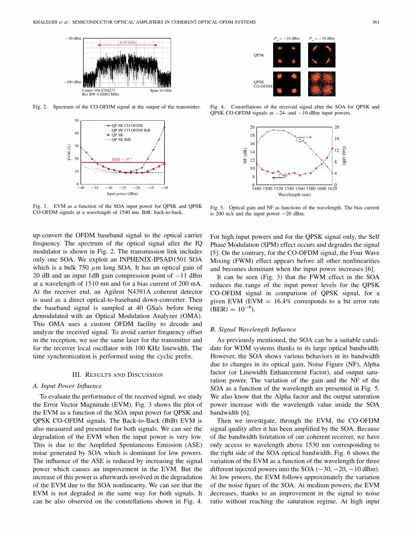
Then we investigate, through the EVM, the CO-OFDMsignal quality after it has been amplified by the SOA. Becauseof the bandwidth limitation of our coherent receiver, we haveonly access to wavelength above 1530 nm corresponding tothe right side of the SOA optical bandwidth. Fig. 6 shows thevariation of the EVM as a function of the wavelength for threedifferent injected powers into the SOA (−30, −20, −10 dBm).At low powers, the EVM follows approximately the variationof the noise figure of the SOA. At medium powers, the EVMdecreases, thanks to an improvement in the signal to noiseratio without reaching the saturation regime. At high input
562 IEEE PHOTONICS TECHNOLOGY LETTERS, VOL. 24, NO. 7, APRIL 1, 2012
EV
M (
%)
Wavelength (nm)
0
10
20
30
40
50
1530 15501540 1560 1570 1580 1590 1600 1610 1620
Pin � −30 dBm
Pin � −20 dBm
Pin � −10 dBm
Fig. 6. EVM of a QPSK CO-OFDM signal as a function of the wavelengthfor three injected powers into the SOA (−30, −20, −10 dBm).
Cha
nge
in E
VM
(%
)
Number of subcarriers
0
2
4
6
8
10
12
16 6432 128 256 512 1024
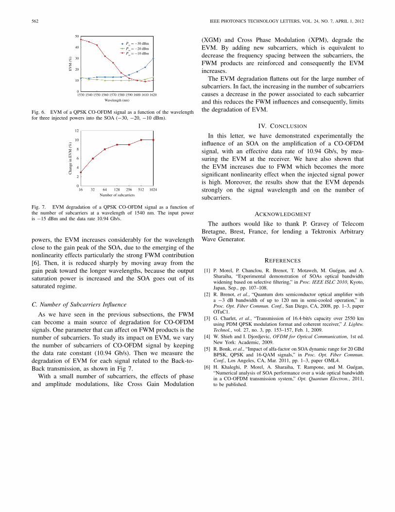
Fig. 7. EVM degradation of a QPSK CO-OFDM signal as a function ofthe number of subcarriers at a wavelength of 1540 nm. The input poweris −15 dBm and the data rate 10.94 Gb/s.
powers, the EVM increases considerably for the wavelengthclose to the gain peak of the SOA, due to the emerging of thenonlinearity effects particularly the strong FWM contribution[6]. Then, it is reduced sharply by moving away from thegain peak toward the longer wavelengths, because the outputsaturation power is increased and the SOA goes out of itssaturated regime.
C. Number of Subcarriers Influence
As we have seen in the previous subsections, the FWMcan become a main source of degradation for CO-OFDMsignals. One parameter that can affect on FWM products is thenumber of subcarriers. To study its impact on EVM, we varythe number of subcarriers of CO-OFDM signal by keepingthe data rate constant (10.94 Gb/s). Then we measure thedegradation of EVM for each signal related to the Back-to-Back transmission, as shown in Fig 7.
With a small number of subcarriers, the effects of phaseand amplitude modulations, like Cross Gain Modulation
(XGM) and Cross Phase Modulation (XPM), degrade theEVM. By adding new subcarriers, which is equivalent todecrease the frequency spacing between the subcarriers, theFWM products are reinforced and consequently the EVMincreases.
The EVM degradation flattens out for the large number ofsubcarriers. In fact, the increasing in the number of subcarrierscauses a decrease in the power associated to each subcarrierand this reduces the FWM influences and consequently, limitsthe degradation of EVM.
IV. CONCLUSION
In this letter, we have demonstrated experimentally theinfluence of an SOA on the amplification of a CO-OFDMsignal, with an effective data rate of 10.94 Gb/s, by mea-suring the EVM at the receiver. We have also shown thatthe EVM increases due to FWM which becomes the moresignificant nonlinearity effect when the injected signal poweris high. Moreover, the results show that the EVM dependsstrongly on the signal wavelength and on the number ofsubcarriers.
ACKNOWLEDGMENT
The authors would like to thank P. Gravey of TelecomBretagne, Brest, France, for lending a Tektronix ArbitraryWave Generator.
REFERENCES
[1] P. Morel, P. Chanclou, R. Brenot, T. Motaweh, M. Guégan, and A.Sharaiha, “Experimental demonstration of SOAs optical bandwidthwidening based on selective filtering,” in Proc. IEEE ISLC 2010, Kyoto,Japan, Sep., pp. 107–108.
[2] R. Brenot, et al., “Quantum dots semiconductor optical amplifier witha −3 dB bandwidth of up to 120 nm in semi-cooled operation,” inProc. Opt. Fiber Commun. Conf., San Diego, CA, 2008, pp. 1–3, paperOTuC1.
[3] G. Charlet, et al., “Transmission of 16.4-bit/s capacity over 2550 kmusing PDM QPSK modulation format and coherent receiver,” J. Lightw.Technol., vol. 27, no. 3, pp. 153–157, Feb. 1, 2009.
[4] W. Shieh and I. Djordjevic, OFDM for Optical Communication, 1st ed.New York: Academic, 2009.
[5] R. Bonk, et al., “Impact of alfa-factor on SOA dynamic range for 20 GBdBPSK, QPSK and 16-QAM signals,” in Proc. Opt. Fiber Commun.Conf., Los Angeles, CA, Mar. 2011, pp. 1–3, paper OML4.
[6] H. Khaleghi, P. Morel, A. Sharaiha, T. Rampone, and M. Guégan,“Numerical analysis of SOA performance over a wide optical bandwidthin a CO-OFDM transmission system,” Opt. Quantum Electron., 2011,to be published.