selected works by lauren garvey
DESCRIPTION
Architecture student portfolioTRANSCRIPT
LAUREN GARVEYARCHITECTURAL DESIGN SELECTED WORKS

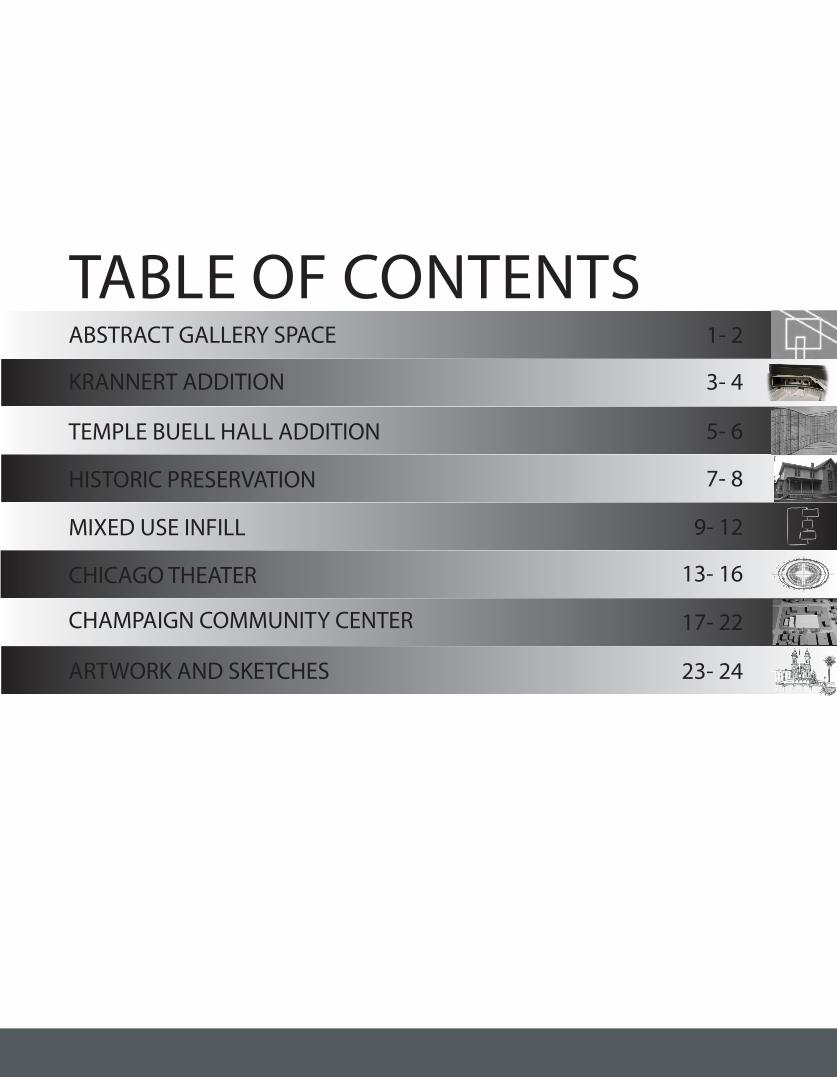
TABLE OF CONTENTSABSTRACT GALLERY SPACE
KRANNERT ADDITION
TEMPLE BUELL HALL ADDITION
HISTORIC PRESERVATION
MIXED USE INFILL
CHICAGO THEATER
CHAMPAIGN COMMUNITY CENTER
ARTWORK AND SKETCHES
UP
UP
UP
UP
UP
UP
UP
UP
UP
DN
DN
DN
UP
DN
DN
DN
18 19
2021
26
27
1- 2
3- 4
5- 6
7- 8
9- 12
13- 16
17- 22
23- 24
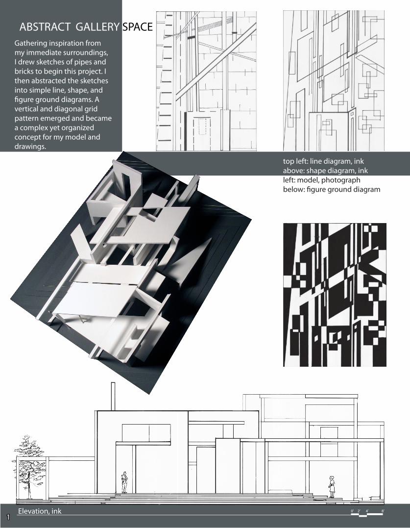
ABSTRACT GALLERY SPACEGathering inspiration from my immediate surroundings, I drew sketches of pipes and bricks to begin this project. I then abstracted the sketches into simple line, shape, and figure ground diagrams. A vertical and diagonal grid pattern emerged and became a complex yet organized concept for my model and drawings.
Elevation, ink 0’ 2’ 4’ 8’
1
top left: line diagram, inkabove: shape diagram, inkleft: model, photographbelow: figure ground diagram
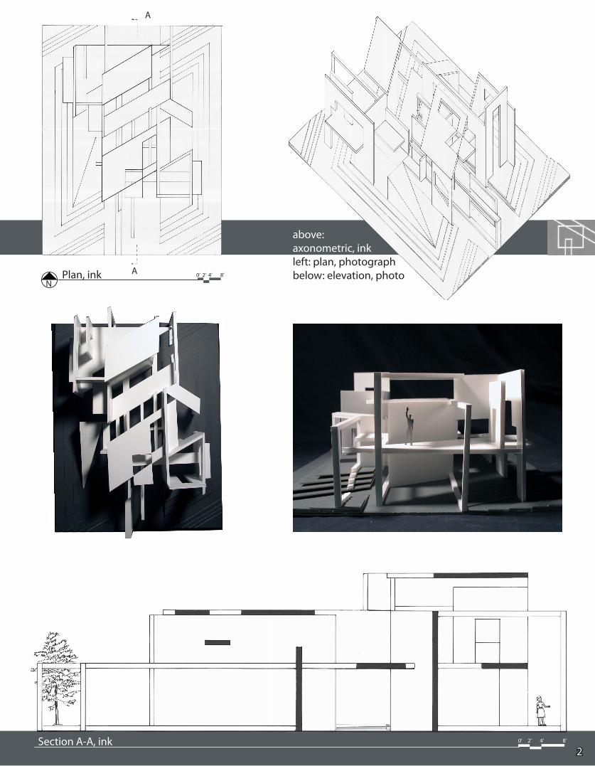
above: axonometric, inkleft: plan, photographbelow: elevation, photo
NPlan, ink 0’ 2’ 4’ 8’A
A
Section A-A, ink2
0’ 2’ 4’ 8’
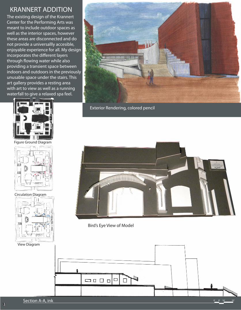
KRANNERT ADDITIONThe existing design of the Krannert Center for the Performing Arts was meant to include outdoor spaces as well as the interior spaces, however these areas are disconnected and do not provide a universallly accesible, enjoyable experience for all. My design incorporates the different layers through flowing water while also providing a transient space between indoors and outdoors in the previously unusable space under the stairs. This art gallery provides a resting area with art to view as well as a running waterfall to give a relaxed spa feel.
0’ 8’ 16’ 32’ Section A-A, ink3
Bird’s Eye View of Model
Figure Ground Diagram
Circulation Diagram
View Diagram
Exterior Rendering, colored pencil
0’ 8’ 16’ 32’
4
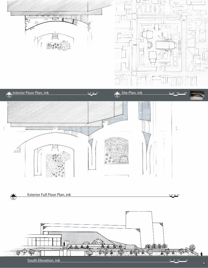
0’ 8’ 16’ 32’Interior Floor Plan, inkN
0 ‘ 32’ 64’ 128’ Site Plan, inkN
0’ 8’ 16’ 32’Exterior Full Floor Plan, inkN
0’ 8’ 16’ 32’South Elevation, ink
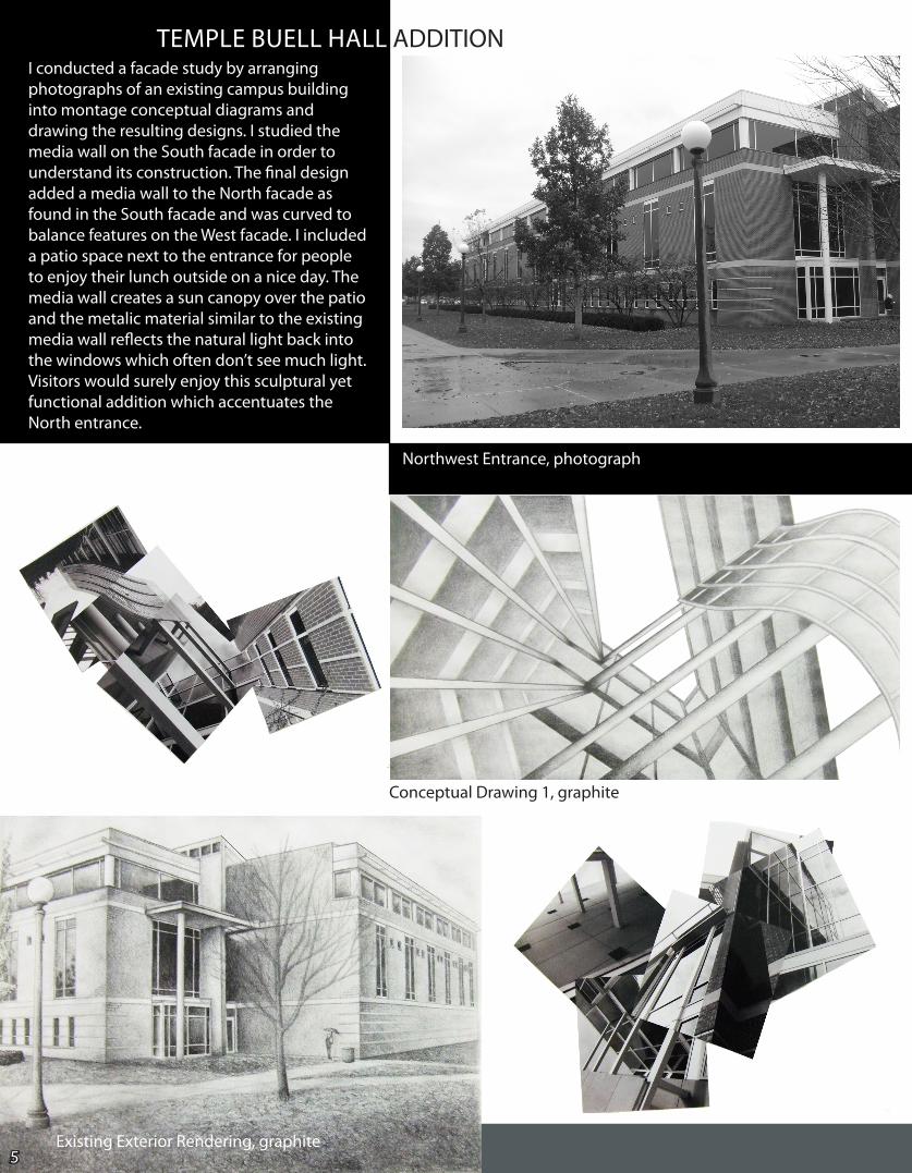
TEMPLE BUELL HALL ADDITIONI conducted a facade study by arranging photographs of an existing campus building into montage conceptual diagrams and drawing the resulting designs. I studied the media wall on the South facade in order to understand its construction. The final design added a media wall to the North facade as found in the South facade and was curved to balance features on the West facade. I included a patio space next to the entrance for people to enjoy their lunch outside on a nice day. The media wall creates a sun canopy over the patio and the metalic material similar to the existing media wall reflects the natural light back into the windows which often don’t see much light. Visitors would surely enjoy this sculptural yet functional addition which accentuates the North entrance.
Conceptual Drawing 1, graphite
5
Northwest Entrance, photograph
Existing Exterior Rendering, graphite
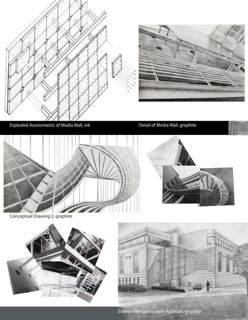
Exploded Axonometric of Media Wall, ink Detail of Media Wall, graphite
Conceptual Drawing 2, graphite
6Exterior Rendering with Addition, graphite
7
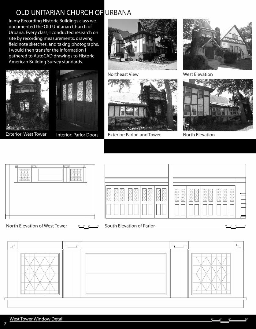
OLD UNITARIAN CHURCH OF URBANA
South Elevation of Parlor 0’ 2’ 4’ 8’
West Tower Window Detail 0” 4” 8” 16”
North Elevation
West ElevationNortheast View
Exterior: Parlor and TowerExterior: West Tower Interior: Parlor Doors
In my Recording Historic Buildings class we documented the Old Unitarian Church of Urbana. Every class, I conducted research on site by recording measurements, drawing field note sketches, and taking photographs. I would then transfer the information I gathered to AutoCAD drawings to Historic American Building Survey standards.
North Elevation of West Tower 0’ 1’ 2’ 4’
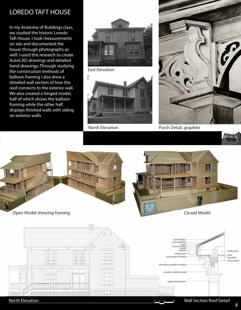
LOREDO TAFT HOUSE
8North Elevation 0’ 2’ 4’ 8’
Open Model showing framing Closed Model
Porch Detail, graphite
In my Anatomy of Buildings class, we studied the historic Loredo Taft House. I took measurements on site and documented the house through photographs as well. I used this research to create AutoCAD drawings and detailed hand drawings. Through studying the constrcution methods of balloon framing I also drew a detailed wall section of how the roof connects to the exterior wall. We also created a hinged model, half of which shows the balloon framing while the other half displays finished walls with siding on exterior walls.
North Elevation
East Elevation
roof shinglesroof sheathing
fasciacommon rafter
headerlookout
metal guttertop wooden molding
decorative wodden molding
wooden molded capital
supporting column
ceiling joist
eavetop platefrieze board
Wall Section Roof Detail
9
B
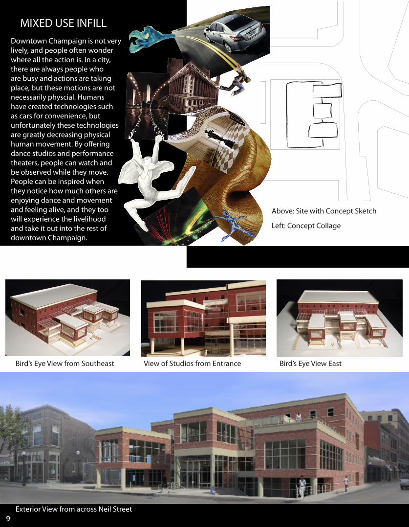
Exterior View from across Neil Street
MIXED USE INFILLDowntown Champaign is not very lively, and people often wonder where all the action is. In a city, there are always people who are busy and actions are taking place, but these motions are not necessarily physcial. Humans have created technologies such as cars for convenience, but unfortunately these technologies are greatly decreasing physical human movement. By offering dance studios and performance theaters, people can watch and be observed while they move. People can be inspired when they notice how much others are enjoying dance and movement and feeling alive, and they too will experience the livelihood and take it out into the rest of downtown Champaign.
Bird’s Eye View from Southeast View of Studios from Entrance Bird’s Eye View East
Above: Site with Concept Sketch
Left: Concept Collage
B
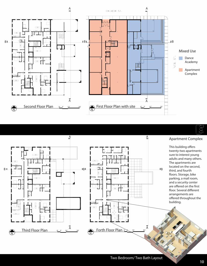
Second Floor PlanN
0’ 5’ 15’ 35’
Third Floor PlanN
0’ 5’ 15’ 35’ Forth Floor PlanN
0’ 5’ 15’ 35’
First Floor Plan with siteN
0’ 5’ 15’ 35’
Two Bedroom/ Two Bath Layout
Apartment Complex
This building offers twenty-two apartments sure to interest young adults and many others. The apartments are located on the second, third, and fourth floors. Storage, bike parking, a mail room, and a security center are offered on the first floor. Several different arrangements are offered throughout the building.
A A
AA
B B B
AA
A A
B B
Mixed Use
Dance Academy
ApartmentComplex
10
11
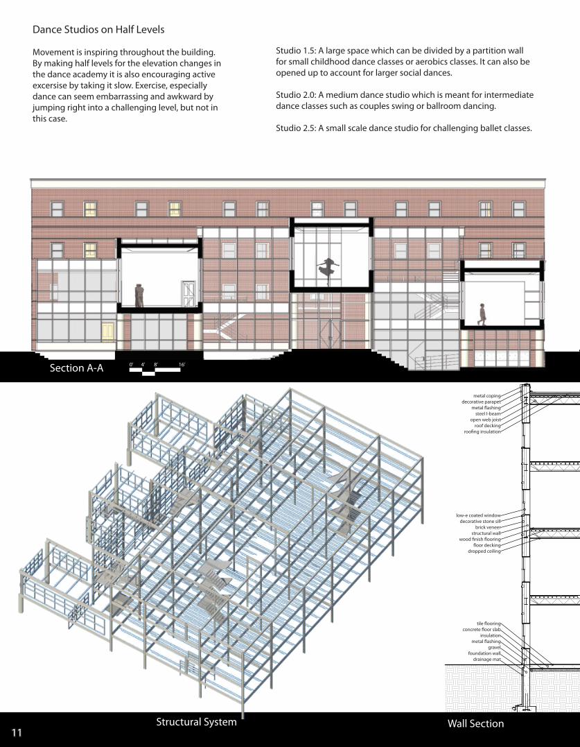
Dance Studios on Half Levels
Movement is inspiring throughout the building. By making half levels for the elevation changes in the dance academy it is also encouraging active excersise by taking it slow. Exercise, especially dance can seem embarrassing and awkward by jumping right into a challenging level, but not in this case.
Studio 1.5: A large space which can be divided by a partition wall for small childhood dance classes or aerobics classes. It can also be opened up to account for larger social dances.
Studio 2.0: A medium dance studio which is meant for intermediate dance classes such as couples swing or ballroom dancing.
Studio 2.5: A small scale dance studio for challenging ballet classes.
0’ 4’ 8’ 16’Section A-A
Structural System Wall Section
metal copingdecorative parapet
metal flashingsteel I-beam
open web joistroof decking
roofing insulation
low-e coated windowdecorative stone sill
brick veneerstructural wall
wood finish flooringfloor decking
dropped ceiling
tile flooring concrete floor slab
insulationmetal flashing
gravelfoundation wall
drainage mat
12
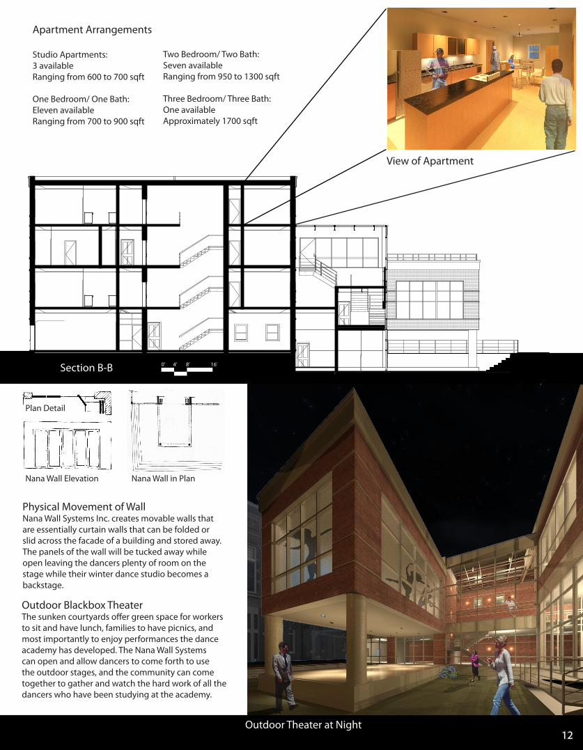
Outdoor Blackbox TheaterThe sunken courtyards offer green space for workers to sit and have lunch, families to have picnics, and most importantly to enjoy performances the dance academy has developed. The Nana Wall Systems can open and allow dancers to come forth to use the outdoor stages, and the community can come together to gather and watch the hard work of all the dancers who have been studying at the academy.
Nana Wall in Plan
Plan Detail
Nana Wall Elevation
0’ 4’ 8’ 16’Section B-B
Outdoor Theater at Night
View of Apartment
Apartment Arrangements
Studio Apartments: 3 availableRanging from 600 to 700 sqft
One Bedroom/ One Bath:Eleven availableRanging from 700 to 900 sqft
Two Bedroom/ Two Bath:Seven availableRanging from 950 to 1300 sqft
Three Bedroom/ Three Bath:One availableApproximately 1700 sqft
Physical Movement of WallNana Wall Systems Inc. creates movable walls that are essentially curtain walls that can be folded or slid across the facade of a building and stored away. The panels of the wall will be tucked away while open leaving the dancers plenty of room on the stage while their winter dance studio becomes a backstage.
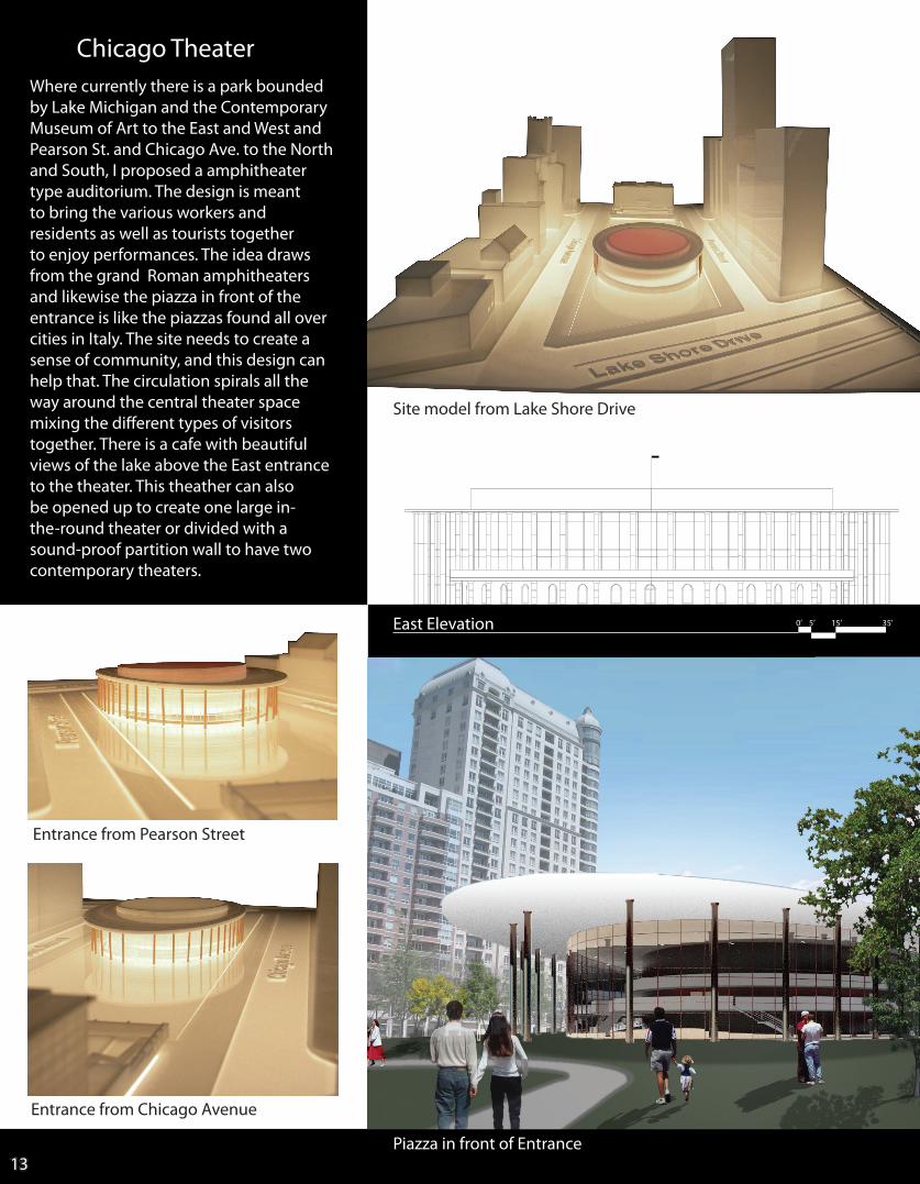
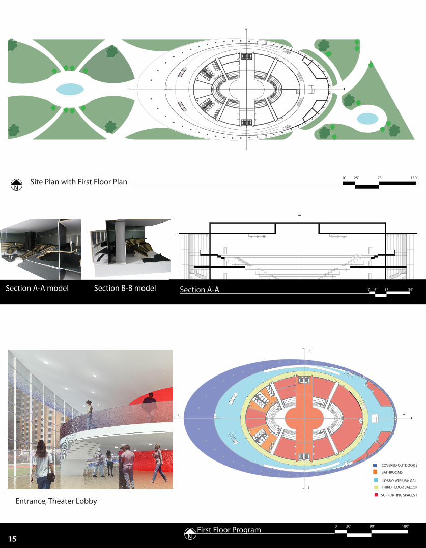
Where currently there is a park bounded by Lake Michigan and the Contemporary Museum of Art to the East and West and Pearson St. and Chicago Ave. to the North and South, I proposed a amphitheater type auditorium. The design is meant to bring the various workers and residents as well as tourists together to enjoy performances. The idea draws from the grand Roman amphitheaters and likewise the piazza in front of the entrance is like the piazzas found all over cities in Italy. The site needs to create a sense of community, and this design can help that. The circulation spirals all the way around the central theater space mixing the different types of visitors together. There is a cafe with beautiful views of the lake above the East entrance to the theater. This theather can also be opened up to create one large in-the-round theater or divided with a sound-proof partition wall to have two contemporary theaters.
Piazza in front of Entrance
Site model from Lake Shore Drive
East Elevation 0’ 5’ 15’ 35’
13
Entrance from Chicago Avenue
Chicago Theater
Entrance from Pearson Street
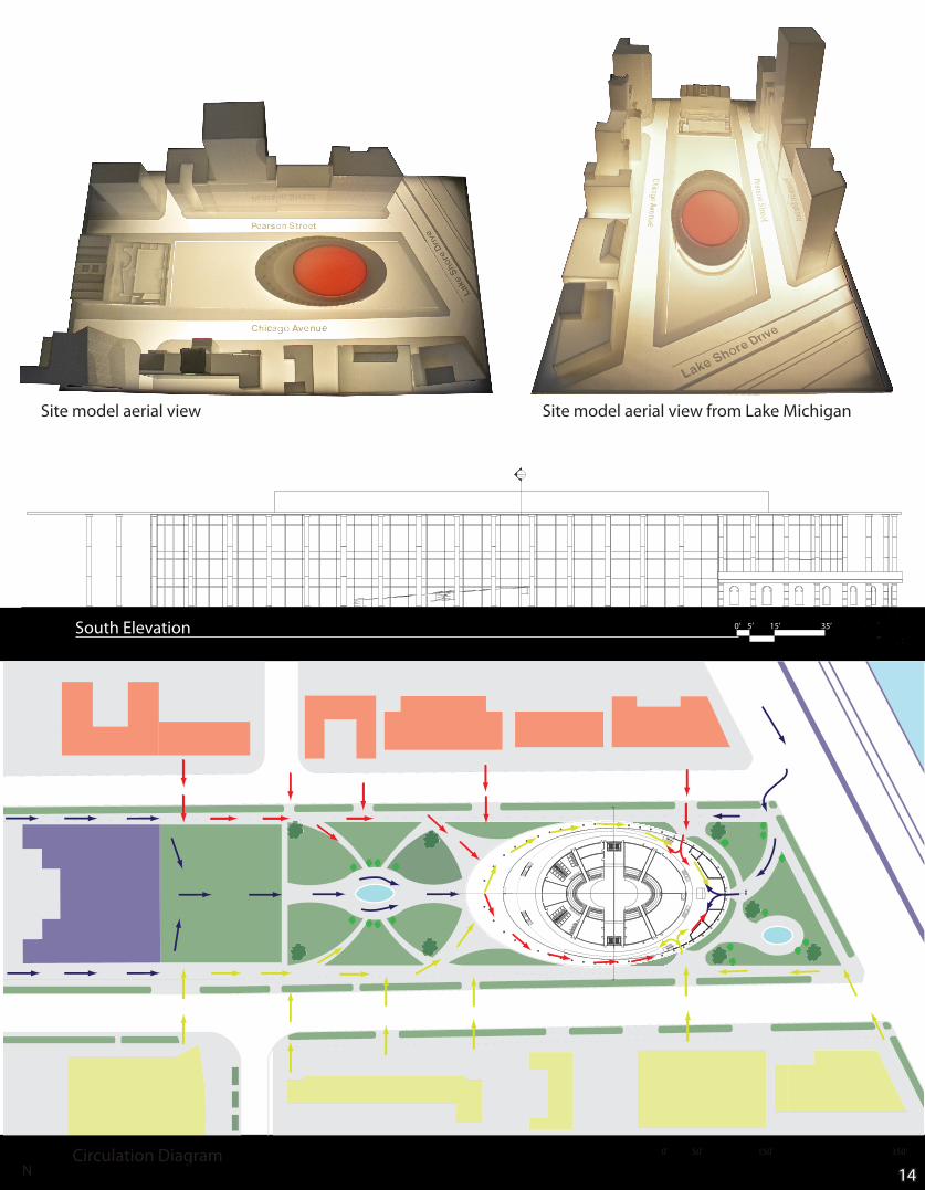
South Elevation
Site model aerial view
0’ 5’ 15’ 35’
1450’ 150’ 350’ N0’ 50’ 150’ 350’Circulation Diagram
N
----
Site model aerial view from Lake Michigan
UP
UP
UP
UP
UP
UP
UP
UP
UP
DN
DN
DN
UP
DN
DN
DN
18 19
2021
26
27
50’ 150’ 350’ N
FIRST FLOOR AND SITE
COVERED OUTDOOR S
BATHROOMS
LOBBY/ ATRIUM/ GALL
THIRD FLOOR BALCON
SUPPORTING SPACES FN
FLOOR PLAN
A A
B
B
15
Section A-A 0’ 5’ 15’ 35’ Section A-A model Section B-B model
Site Plan with First Floor PlanN
0’ 25’ 75’ 150’
Entrance, Theater Lobby
First Floor Program 0’ 30’ 90’ 180’
N
0’ 25’ 75’ 150’
0’ 30’ 90’ 180’
16
Section B-B 0’ 5’ 15’ 35’
UP
UP
UP
UP
UP
UP
UP
UP
UP
DN
DN
DN
UP
DN
DN
DN
18 19
2021
26
27
PEARSON STREET
CHICAGO AVE
LAKE SHORE DRIVE
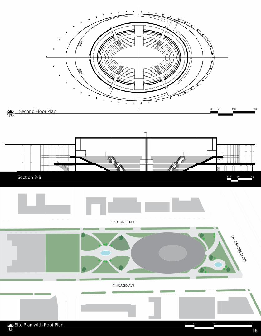
0’ 50’ 150’ 350’Site Plan with Roof PlanN
Second Floor PlanN
0’ 50’ 150’ 300’
Site Plan N
0’ 20’ 40’ 80’
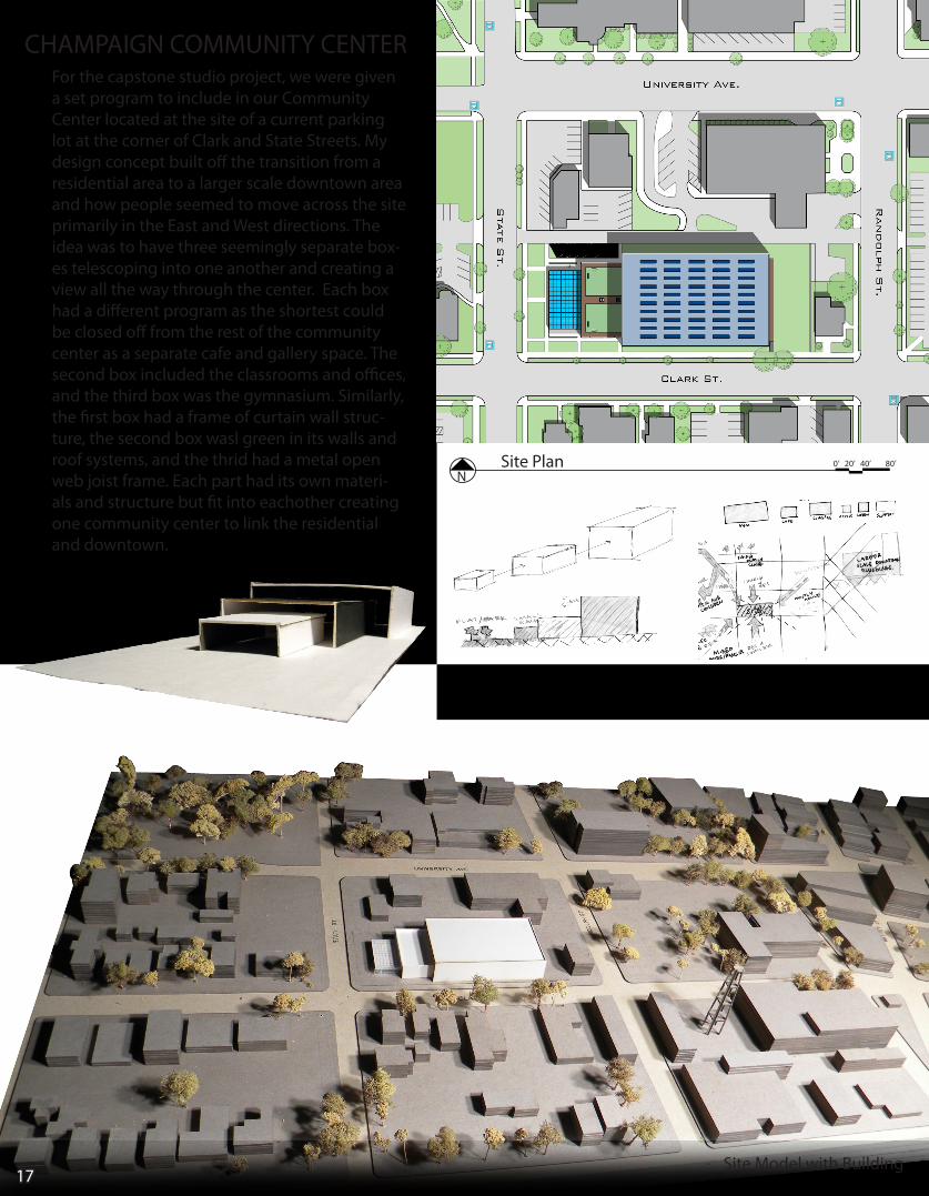
CHAMPAIGN COMMUNITY CENTER
Concept Model and Sketches
Site Model with Building
For the capstone studio project, we were given a set program to include in our Community Center located at the site of a current parking lot at the corner of Clark and State Streets. My design concept built off the transition from a residential area to a larger scale downtown area and how people seemed to move across the site primarily in the East and West directions. The idea was to have three seemingly separate box-es telescoping into one another and creating a view all the way through the center. Each box had a different program as the shortest could be closed off from the rest of the community center as a separate cafe and gallery space. The second box included the classrooms and offices, and the third box was the gymnasium. Similarly, the first box had a frame of curtain wall struc-ture, the second box wasl green in its walls and roof systems, and the thrid had a metal open web joist frame. Each part had its own materi-als and structure but fit into eachother creating one community center to link the residential and downtown.
17
0’ 20’ 40’ 80’
Site Model with Building
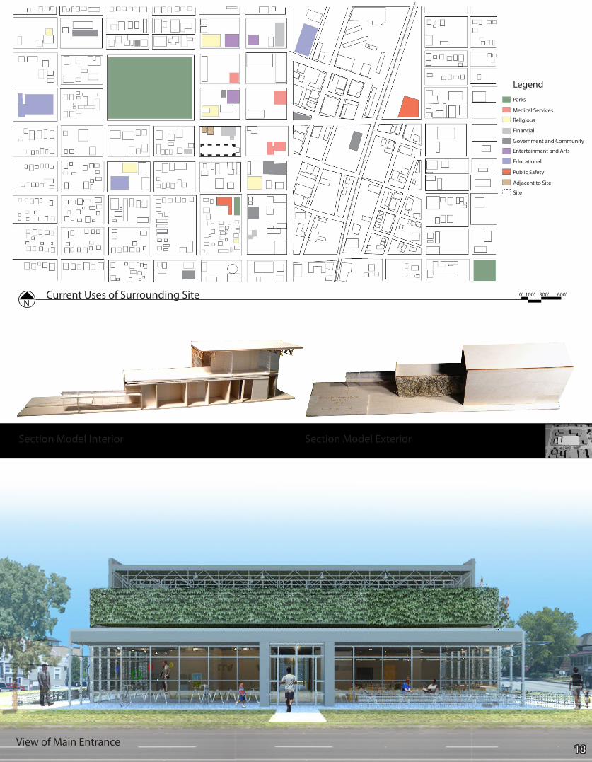
Current Uses of Surrounding SiteN
0’ 100’ 300’ 600’
Section Model Interior Section Model Exterior
LegendParks
Medical Services
Religious
Financial
Government and Community
Entertainment and Arts
Educational
Public Safety
Adjacent to Site
Site
View of Main Entrance18
GreenScreen System
5 6 7 8
15 14 13 12 11 10 9
1
2
3
4272826
25624
29
273130
23 22 21 20 19 6 12 11 10 9 30
Wall Section
Seasonal Interest with changing plants
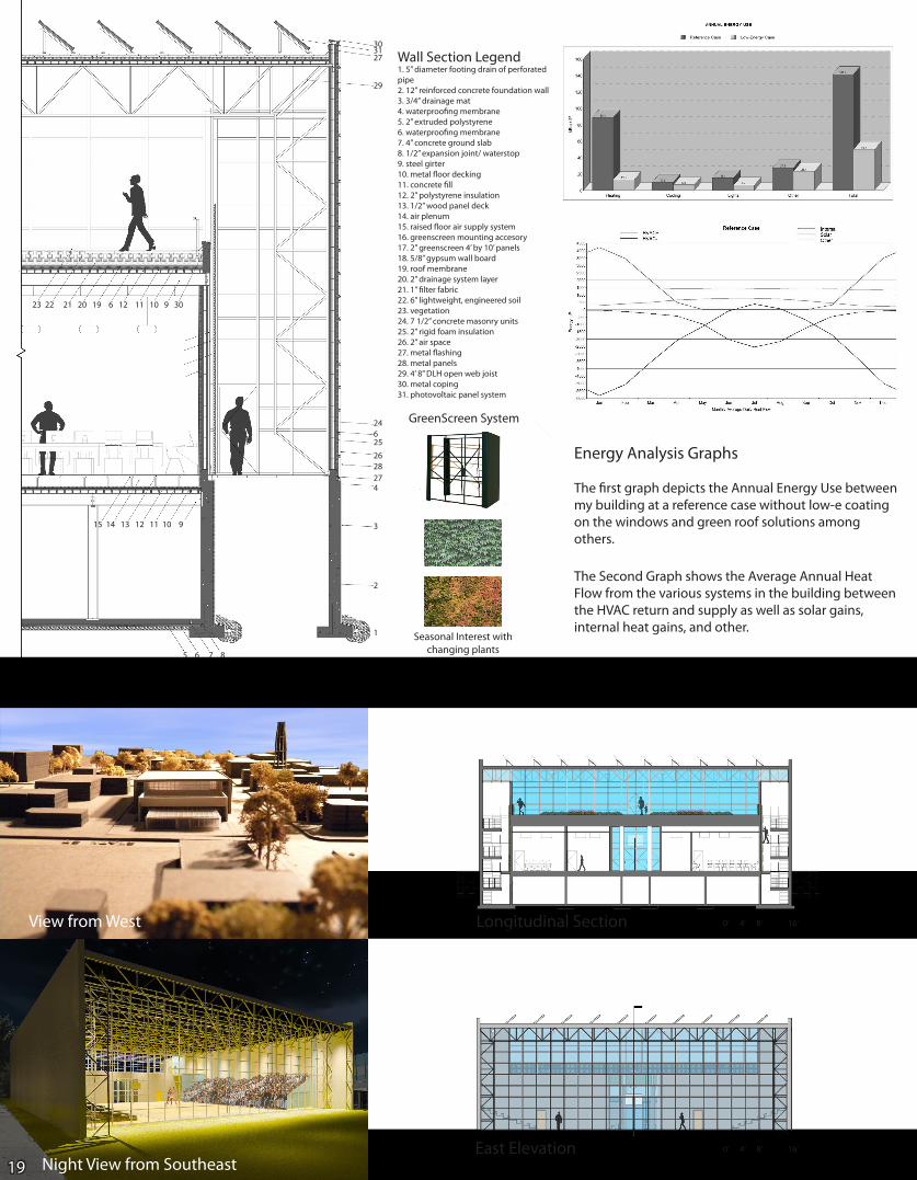
Wall Section Legend1. 5” diameter footing drain of perforated pipe2. 12” reinforced concrete foundation wall3. 3/4” drainage mat4. waterproofing membrane5. 2” extruded polystyrene6. waterproofing membrane7. 4” concrete ground slab8. 1/2” expansion joint/ waterstop9. steel girter10. metal floor decking11. concrete fill12. 2” polystyrene insulation13. 1/2” wood panel deck14. air plenum15. raised floor air supply system16. greenscreen mounting accesory17. 2” greenscreen 4’ by 10’ panels18. 5/8” gypsum wall board19. roof membrane20. 2” drainage system layer21. 1” filter fabric22. 6” lightweight, engineered soil23. vegetation24. 7 1/2” concrete masonry units25. 2” rigid foam insulation26. 2” air space27. metal flashing28. metal panels29. 4’ 8” DLH open web joist30. metal coping31. photovoltaic panel system
Energy Analysis Graphs
The first graph depicts the Annual Energy Use between my building at a reference case without low-e coating on the windows and green roof solutions among others.
The Second Graph shows the Average Annual Heat Flow from the various systems in the building between the HVAC return and supply as well as solar gains, internal heat gains, and other.
East Elevation 0’ 4’ 8’ 16’
Night View from Southeast19
View from West Longitudinal Section 0’ 4’ 8’ 16’
Latitudinal Section 0’ 4’ 8’ 16’
South Elevation
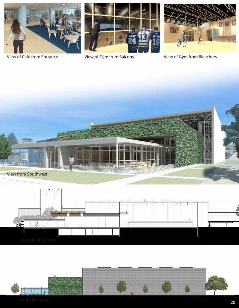
View of Cafe from Entrance View of Gym from Balcony View of Gym from Bleachers
0’ 4’ 8’ 16’
View from Southwest
20
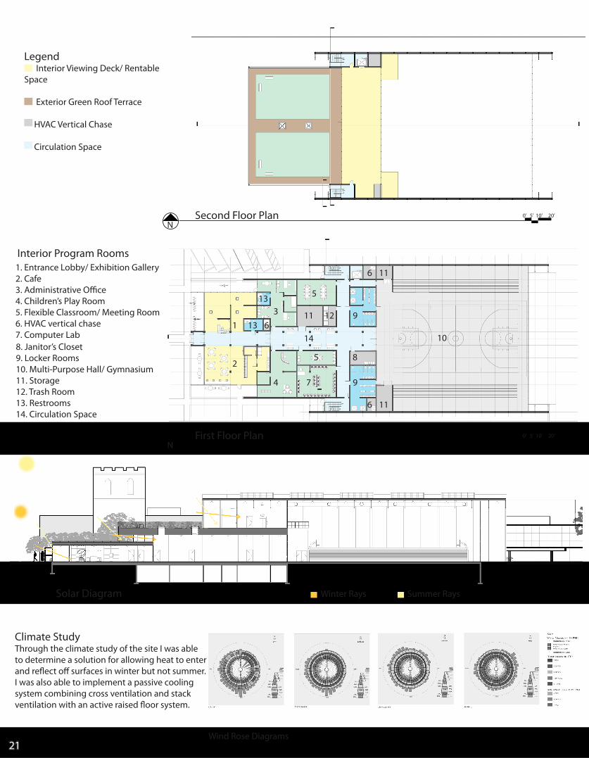
Solar Diagram Winter Rays Summer Rays
Legend Interior Viewing Deck/ Rentable Space
Exterior Green Roof Terrace
HVAC Vertical Chase
Circulation Space
Second Floor Plan N
0’ 5’ 10’ 20’
Climate StudyThrough the climate study of the site I was able to determine a solution for allowing heat to enter and reflect off surfaces in winter but not summer.I was also able to implement a passive cooling system combining cross ventilation and stack ventilation with an active raised floor system.
1. Entrance Lobby/ Exhibition Gallery2. Cafe3. Administrative Office4. Children’s Play Room5. Flexible Classroom/ Meeting Room6. HVAC vertical chase7. Computer Lab8. Janitor’s Closet9. Locker Rooms10. Multi-Purpose Hall/ Gymnasium11. Storage12. Trash Room13. Restrooms14. Circulation Space
Interior Program Rooms
1
2
3
4
5
5
7
8
9
9
10
11
11
11
1213
13
14
6
6
6
First Floor Plan N
0’ 5’ 10’ 20’
21Wind Rose Diagrams
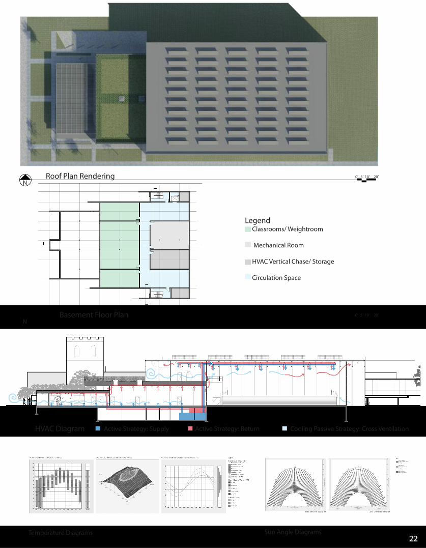
HVAC Diagram Active Strategy: Supply Cooling Passive Strategy: Cross VentilationActive Strategy: Return
Roof Plan Rendering 0’ 5’ 10’ 20’
Legend Classrooms/ Weightroom
Mechanical Room
HVAC Vertical Chase/ Storage
Circulation Space
Basement Floor Plan N
0’ 5’ 10’ 20’
N
22Temperature Diagrams Sun Angle Diagrams
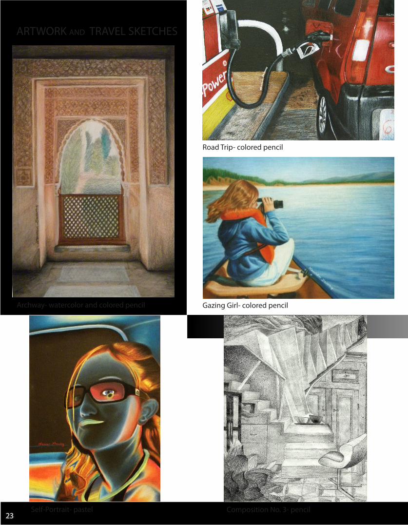
ARTWORK and TRAVEL SKETCHES
Self-Portrait- pastel23
Archway- watercolor and colored pencil
Road Trip- colored pencil
Gazing Girl- colored pencil
Composition No. 3- pencil
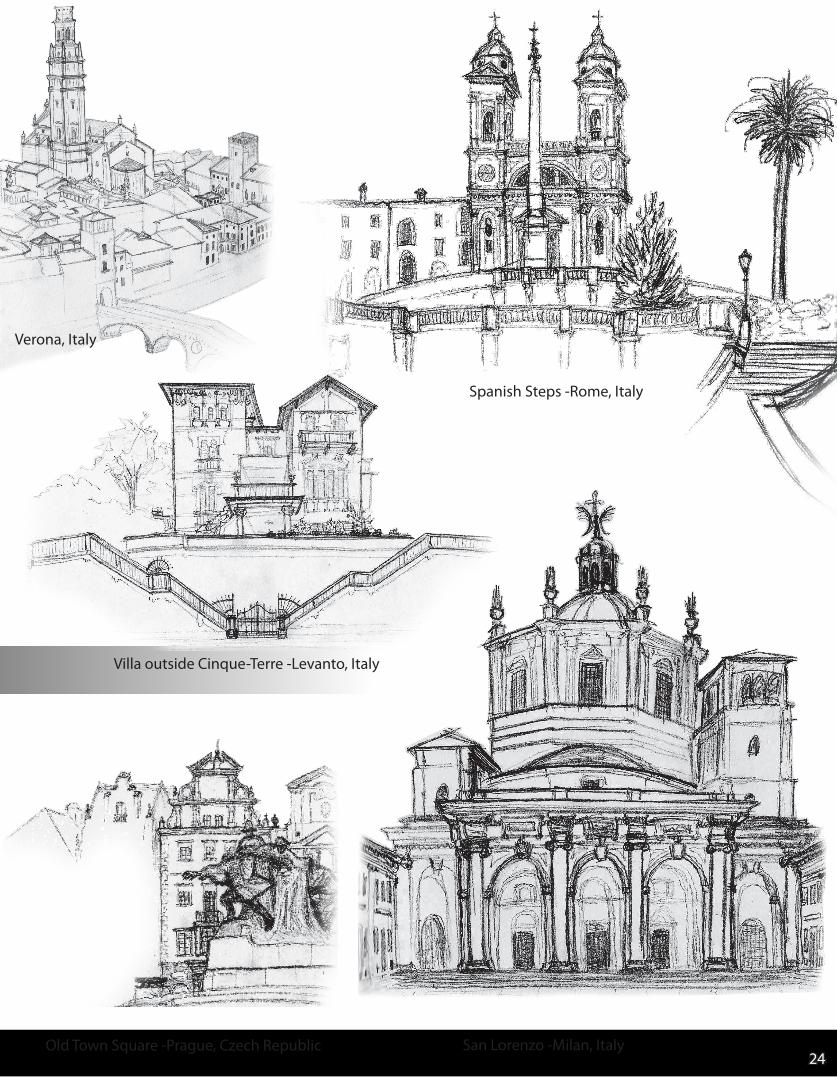
Old Town Square -Prague, Czech Republic San Lorenzo -Milan, Italy24
Villa outside Cinque-Terre -Levanto, Italy
Spanish Steps -Rome, Italy
Verona, Italy

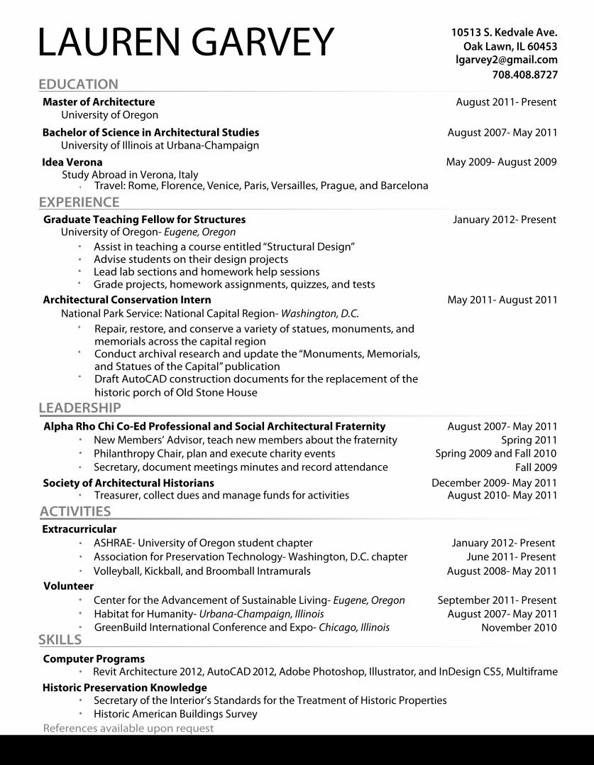
LAUREN GARVEY 10513 S. Kedvale Ave.Oak Lawn, IL 60453
[email protected] EDUCATION
Bachelor of Science in Architectural Studies August 2007- May 2011 University of Illinois at Urbana-Champaign
Graduate Teaching Fellow for Structures January 2012- Present
•
Extracurricular
Habitat for Humanity- Urbana-Champaign, IllinoisCenter for the Advancement of Sustainable Living- Eugene, Oregon
GreenBuild International Conference and Expo- Chicago, Illinois
ASHRAE- University of Oregon student chapter
Idea Verona Study Abroad in Verona, Italy
May 2009- August 2009
•
•• Association for Preservation Technology- Washington, D.C. chapter
Volleyball, Kickball, and Broomball Intramurals
•
EXPERIENCE
ACTIVITIES
SKILLS
Architectural Conservation Intern May 2011- August 2011
•
•
•
LEADERSHIP
Volunteer
••
January 2012- PresentJune 2011- Present
August 2008- May 2011
September 2011- PresentAugust 2007- May 2011
November 2010
Alpha Rho Chi Co-Ed Professional and Social Architectural FraternityNew Members’ Advisor, teach new members about the fraternityPhilanthropy Chair, plan and execute charity eventsSecretary, document meetings minutes and record attendance
•August 2007- May 2011
Spring 2011Spring 2009 and Fall 2010
Fall 2009Society of Architectural Historians December 2009- May 2011
Treasurer, collect dues and manage funds for activities
••
•
Computer Programs Revit Architecture 2012, AutoCAD 2012, Adobe Photoshop, Illustrator, and InDesign CS5, Multiframe•
Historic Preservation Knowledge Secretary of the Interior’s Standards for the Treatment of Historic PropertiesHistoric American Buildings Survey
••
August 2010- May 2011
•
National Park Service: National Capital Region- Washington, D.C.
University of Oregon- Eugene, Oregon
Master of Architecture University of Oregon
August 2011- Present
•
•
Travel: Rome, Florence, Venice, Paris, Versailles, Prague, and Barcelona
Assist in teaching a course entitled “Structural Design”Advise students on their design projectsLead lab sections and homework help sessionsGrade projects, homework assignments, quizzes, and tests
Repair, restore, and conserve a variety of statues, monuments, andmemorials across the capital regionConduct archival research and update the “Monuments, Memorials,and Statues of the Capital” publicationDraft AutoCAD construction documents for the replacement of the historic porch of Old Stone House
•
References available upon request