seismic&isolation&of& nuclearstructures...seismic&isolation&of&...
TRANSCRIPT

SEISMIC ISOLATION OF NUCLEAR STRUCTURES
Dr. Annie Kammerer, PE Pacific Earthquake Engineering Research Center, UC Berkeley
Annie Kammerer ConsulGng
Korean Atomic Energy Research InsGtute Daejon Korea
April 2015

Overview
¨ Seismic isolaGon (SI) basics and terminology ¨ Use of SI in non-‐nuclear applicaGons ¨ Use of SI in nuclear applicaGons ¨ Design of SI systems in a risk-‐informed framework ¨ ConstrucGon and operaGonal requirements and special
consideraGons

Seismic IsolaGon Basics
Seismic IsolaGon is a method of decoupling a structure from the supporGng surface through the use of specially designed equipment. Applying the isolaGon layer below the foundaGon is called “base isolaGon.” (the focus of this presentaGon) Equipment and floors can also be isolated.

The inerGa of the structure keeps it in place as the earth moves beneath it. The relaGve displacement between the structure and ground is taken up by isolators. An base isolaGon system is composed of a “forest” of isolators siYng on pedestals (which allow access to the isolators).
Seismic IsolaGon Basics

Isolators/ IsolaGon Interface
FoundaGon -‐lower mat -‐pedestals -‐moat walls
Seismic IsolaGon Basics

Superstructure (enGre structure above the
isolators, acts as a “rigid body”)
Basemat (highly rigid mat
above the isolators)
Seismic IsolaGon Terminology

Moat (space to allow for relaGve movement)
Moat wall (could be used as hard Stop)
Clearance to Hard Stop (Distance large enough to limit pounding. Sets some isolator
properGes)
Seismic IsolaGon Terminology

¨ Low damping rubber bearing ¨ Lead (core) rubber bearing ¨ FricGon pendulum
Common Types of Isolator Units

LNG TANKS, REVITHOUSSA, GREECE Fric6on Pendulum Bearings
Use of SI in LNG FaciliGes
Courtesy of Prof. Andrew Whi^aker

LNG TANKS, INCHON, SOUTH KOREA Low Damping Rubber Bearings
Use of SI in LNG FaciliGes
Courtesy of Prof. Andrew Whi^aker

SAKHALIN II PLATFORMS Fric6on Pendulum Bearings
Use of SI in Natural Gas Pla_orms
Courtesy of Prof. Andrew Whi^aker

Sensi6ve and important Structures and infrastructure in the US
(tens of thousands of buildings worldwide-‐mostly in Japan)
Hearst Mining Building, UC Berkeley
Golden Gate Bridge
San Francisco City Hall
Use of SI in Other Structures

Use of Base isola6on under Nuclear Power
Reactors
Cruas-‐Meysse NPP, France
Koeberg NPP, South Africa
Base IsolaGon of Nuclear FaciliGes

Cruas-‐Meysse NPP Courtesy of Electricite de France
Base IsolaGon of Nuclear FaciliGes

Base IsolaGon of Nuclear FaciliGes
Cruas-‐Meysse NPP
Courtesy of Electricite de France

Other nuclear
applica6ons
Jules Horowitz Research Reactor, France
Tokamak Fusion Re
actor, Fran
ce
Emergency Response Centers at Kashiwazai-‐Kariwa, Fukushima Daiichi, and Fukushima Daini
Base IsolaGon in Nuclear FaciliGes

From INPO 11-‐005 Addendum August 2012 Lessons Learned from the Nuclear Accident at the Fukushima Daiichi Nuclear Power Sta6on “The seismically isolated emergency response centers at the Fukushima Daiichi and Daini nuclear power staGons filled a vital need in protecGng emergency response personnel and ensuring access to the site could be maintained during the accident.”
Experience in the 2011 Earthquake

¨ In 2008 NRC began research in SI ¨ NRC research addressed key items
¤ VerGcal and beyond-‐design-‐basis loading ¤ Development of isolator component for NRC’s SSI Modeling Tool (the ESSI Simulator)
¤ TesGng of full size isolator systems at large loads on eDefence to confirm analysis tools and models
¤ Development of performance-‐based criteria for regulaGon of NPPs using seismic isolaGon systems
¤ Development of determinisGc “rules of thumb” to provide conservaGve factors for performance criteria
¨ Development of NUREG & modeling tools to address NRC staff needs (also feeding into new IAEA guidance)
NRC AcGviGes

NRC-‐sponsored tesGng of SI units

DCPP Time History Lead Rubber Bearing
NRC-‐sponsored tesGng of SI units

Fixed Base Structure
Structure Isolated with FricGon Pendulum and Lead Rubber Bearings
NRC-‐sponsored tesGng of SI units

Drag NRC NUREG
¨ Isolator/IsolaGon system design (approach and tools)
¨ Assurance of isolaGon system performance
¨ Umbilicals and cross-‐over structures
¨ ConstrucGon QA/QC
¨ OperaGons and Maintenance
¨ NUREG developed to provide background informaGon and proposed recommendaGons for RG
Kammerer1, Whi^aker2, and ConstanGnou2
1US NRC 2University of Buffalo
Drag NRC NUREG
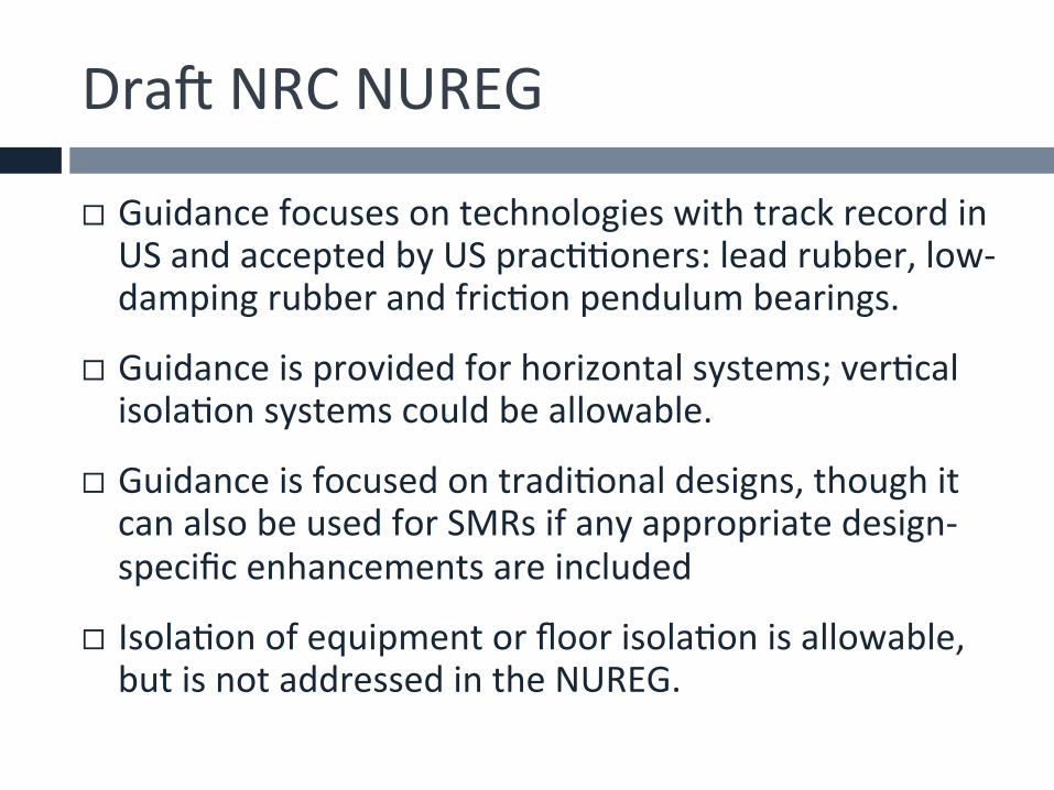
¨ Guidance focuses on technologies with track record in US and accepted by US pracGGoners: lead rubber, low-‐damping rubber and fricGon pendulum bearings.
¨ Guidance is provided for horizontal systems; verGcal isolaGon systems could be allowable.
¨ Guidance is focused on tradiGonal designs, though it can also be used for SMRs if any appropriate design-‐specific enhancements are included
¨ IsolaGon of equipment or floor isolaGon is allowable, but is not addressed in the NUREG.

Guidance Philosophies
¨ The isolators cannot be allowed to fail and should be removed from any realisGc sequence.
¨ Singletons that are safety related must have more stringent design criteria than more convenGonal construcGon.
¨ The potenGal for failure and cliff edge effects is removed through use of a hard stop.
¨ The concepts of FOSID and HCLPF should be incorporated to the extent possible, recognizing that seismic isolators are inherently non-‐linear.
¨ The extended DBE concept discussed in the Near Term Task Force Report should be incorporated.

Guidance Philosophies
¨ Assurance of performance must incorporate a combinaGon of prototype and producGon tesGng to physically demonstrate quanGfiable confidence levels and performance reliability in both the isolators and the umbilicals.
¨ Guidance must consider how seismic isolaGon systems could fit within a cerGfied design framework. (Design of the Basemat up is cerGfied and isolators tuned to the site)
¨ Although the guidance focuses on isolated light water reactor superstructures, the approach should be technology neutral enough to be extended to other designs, such as for small modular reactors.
¨ RealisGc approaches for achieving clear and technically based performance targets should be described.

A hard stop assures survivability
Hard Stop Requirement

TesGng Requirements
Isolator behavior, capacity, and reliability can be determined through a program of prototype tesGng. The isolator unit must have a high confidence of a low probability of failure (HCLPF) at the CHS deformaGon.

Capacity Seismic MoGon Parameter
Cond
iGon
al Probability of Failure
Example of prototype
tesGng at UCSD
TesGng Requirements

TesGng Requirements
All isolators ALSO quality tested to their deformaGon under design basis ground moGon (this will be less than the CHS) to assure that the performance is as expected. This gives very high confidence that the isolaGon system can survive earthquake loading, even if beyond design basis.

Maximum deformaGon under design basis ground moGon
The moat is sized such that there is less than 1% likelihood of any impact of superstructure with the wall under the DBE ground moGon when modeling is performed to account for difference in actual earthquake records (Gme histories) and uncertainGes in parameters.
Prob
ability from
mod
eling
<1% likelihood of impact
Design of Moat

Isolators and/or Isolation system Super-structure
Connections/ umbilicals Moat/Hard Stop
Hazard and Associated
Risk Parameter
Isolation unit and system design and
performance criteria
Approach to demonstrating unit
performance Performance expectations
GMRS+2 The envelope of the RG1.208 GMRS and the minimum foundation input motion3 for each spectral frequency
No long-term change in mechanical properties. 100% confidence of the isolation system surviving without damage when subjected to the mean displacement of the isolator system under the GMRS+ loading.
Production testing must be performed on each isolator for the mean system displacement under the GMRS+ loading level and corresponding axial force.
Superstructure design and performance must conform to NUREG-0800 under GMRS+ loading.
Umbilical line design and performance must conform to NUREG-0800 under GMRS+ loading.
The moat is sized such that there is less than 1% probability of the superstructure contacting the moat or hard stop under GMRS+ loading.
EDB4 GMRS The envelope of the ground moGon amplitude with a mean annual frequency of exceedance of 1x10-‐5 and 167% of the GMRS+ spectral amplitude
90% confidence of each isolator and the isolaGon system surviving without loss of gravity-‐load capacity at the mean displacement under EDB loading.
Prototype tesGng must be performed on a sufficient number of isolators at the CHS5 displacement and the corresponding axial force to demonstrate acceptable performance with 90% confidence. Limited isolator unit damage is acceptable but load-‐carrying capacity must be maintained.
There should be less than a 10% probability of the superstructure contacting the moat or hard stop under EDB loading.
Greater than 90% confidence that each type of safety-related umbilical line, together with its connections, remains functional for the CHS displacement. Performance can be demonstrated by testing, analysis or a combination of both.6
CHS displacement must be equal to or greater than the 90th percentile isolation system displacement under EDB loading. Moat or hard stop designed to survive impact forces associated with 95th percentile EDB isolation system displacement.7 Limited damage to the moat or hard stop is acceptable but the moat or hard stop must perform its intended function.
1) Analysis and design of safety-‐related components and systems should conform to NUREG-‐0800, as in a convenGonal nuclear structure. 2) 10CFR50 Appendix S requires the use of an appropriate free-‐field spectrum with a peak ground acceleraGon of no less than 0.10g at the foundaGon level.
RG1.60 spectral shape anchored at 0.10g is ogen used for this purpose. 3) The analysis can be performed using a single composite spectrum or separately for the GMRS and the minimum spectrum. 4) The analysis can be performed using a single composite spectrum or separately for the 10-‐5 MAFE response spectrum and 167% GMRS. 5) CHS=Clearance to the Hard Stop 6) SC 2 SSCs whose failure could impact the funcGonality of umbilical lines should also remain funcGonal for the CHS displacement. 7) Impact velocity calculated at the displacement equal to the CHS assuming cyclic response of the isolaGon system for moGons associated with the 95th
percenGle (or greater) EDB displacement.
Two Hazard Levels Used for Design and Assessment
Ground Mo6on Response Spectrum + same as for new non-‐SI structures
10-‐4 ground moGon with minimum FIRS (NRC Regulatory Guide 1.208)
Extended Design Basis GMRS
10-‐5 ground moGon or 1.67xDBGM

Isolators and/or Isolation system Super-structure
Connections/ umbilicals Moat/Hard Stop
Hazard and Associated
Risk Parameter
Isolation unit and system design and
performance criteria
Approach to demonstrating unit
performance Performance expectations
GMRS+2 The envelope of the RG1.208 GMRS and the minimum foundation input motion3 for each spectral frequency
No long-term change in mechanical properties. 100% confidence of the isolation system surviving without damage when subjected to the mean displacement of the isolator system under the GMRS+ loading.
Production testing must be performed on each isolator for the mean system displacement under the GMRS+ loading level and corresponding axial force.
Superstructure design and performance must conform to NUREG-0800 under GMRS+ loading.
Umbilical line design and performance must conform to NUREG-0800 under GMRS+ loading.
The moat is sized such that there is less than 1% probability of the superstructure contacting the moat or hard stop under GMRS+ loading.
EDB4 GMRS The envelope of the ground moGon amplitude with a mean annual frequency of exceedance of 1x10-‐5 and 167% of the GMRS+ spectral amplitude
90% confidence of each isolator and the isolaGon system surviving without loss of gravity-‐load capacity at the mean displacement under EDB loading.
Prototype tesGng must be performed on a sufficient number of isolators at the CHS5 displacement and the corresponding axial force to demonstrate acceptable performance with 90% confidence. Limited isolator unit damage is acceptable but load-‐carrying capacity must be maintained.
There should be less than a 10% probability of the superstructure contacting the moat or hard stop under EDB loading.
Greater than 90% confidence that each type of safety-related umbilical line, together with its connections, remains functional for the CHS displacement. Performance can be demonstrated by testing, analysis or a combination of both.6
CHS displacement must be equal to or greater than the 90th percentile isolation system displacement under EDB loading. Moat or hard stop designed to survive impact forces associated with 95th percentile EDB isolation system displacement.7 Limited damage to the moat or hard stop is acceptable but the moat or hard stop must perform its intended function.
1) Analysis and design of safety-‐related components and systems should conform to NUREG-‐0800, as in a convenGonal nuclear structure. 2) 10CFR50 Appendix S requires the use of an appropriate free-‐field spectrum with a peak ground acceleraGon of no less than 0.10g at the foundaGon level.
RG1.60 spectral shape anchored at 0.10g is ogen used for this purpose. 3) The analysis can be performed using a single composite spectrum or separately for the GMRS and the minimum spectrum. 4) The analysis can be performed using a single composite spectrum or separately for the 10-‐5 MAFE response spectrum and 167% GMRS. 5) CHS=Clearance to the Hard Stop 6) SC 2 SSCs whose failure could impact the funcGonality of umbilical lines should also remain funcGonal for the CHS displacement. 7) Impact velocity calculated at the displacement equal to the CHS assuming cyclic response of the isolaGon system for moGons associated with the 95th
percenGle (or greater) EDB displacement.
Performance Criteria for the Isolator and Isola6on System
• Design and Performance Criteria • Approach to demonstra6ng Performance
Performance Criteria for the Superstructure, Connec6ons/umbilicals and Moat/hard stop

Isolators and/or Isolation system Super-structure
Connections/ umbilicals Moat/Hard Stop
Hazard and Associated
Risk Parameter
Isolation unit and system design and performance
criteria
Approach to demonstrating unit
performance Performance expectations
GMRS+2 Envelope of the RG1.208 GMRS and the minimum foundation input motion3 for each spectral frequency
No long-term change in mechanical properties. 100% confidence of the isolation system surviving without damage when subjected to the mean displacement of the isolator system under the GMRS+ loading.
Production testing must be performed on each isolator for the mean system displacement under the GMRS+ loading level and corresponding axial force.
Super-structure design and performance must conform to NUREG-0800 under GMRS+ loading.
Umbilical line design and performance must conform to NUREG-0800 under GMRS+ loading.
The moat is sized such that there is less than 1% probability of the superstructure contacting the moat or hard stop under GMRS+ loading.
2) 10CFR50 Appendix S requires the use of an appropriate free-‐field spectrum with a peak ground acceleraGon of no less than 0.10g at the foundaGon level. RG1.60 spectral shape anchored at 0.10g is ogen used for this purpose.
3) The analysis can be performed using a single composite spectrum or separately for the GMRS and the minimum spectrum.
100% confidence in the isolators achieved through produc6on tes6ng of each
isolator
Super structure and internals
designed to ISRS from the design basis ground
mo6on
moat sized for <1% prob. of impact
GMRS
+
Isolators and/or Isolation system Super-structure
Connections/ umbilicals Moat/Hard Stop
Hazard and Associated
Risk Parameter
Isolation unit and system design
and performance criteria
Approach to demonstrating unit
performance Performance expectations
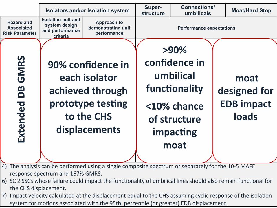
EDB4 GMRS The envelope of the ground moGon amplitude with a mean annual frequency of exceedance of 1x10-‐5 and 167% of the GMRS+ spectral amplitude
90% confidence of each isolator and the isolaGon system surviving without loss of gravity-‐load capacity at the mean displacement under EDB loading.
Prototype tesGng must be performed on a sufficient number of isolators at the CHS5 displacement and the corresponding axial force to demonstrate acceptable performance with 90% confidence. Limited isolator unit damage is acceptable but load-‐carrying capacity must be maintained.
There should be less than a 10% probability of the super-structure contacting the moat or hard stop under EDB loading.
Greater than 90% confidence that each type of safety-related umbilical line, together with its connections, remains functional for the CHS displacement. Performance can be demonstrated by testing, analysis or a combination of both.6
CHS displacement must be equal to or greater than the 90th percentile isolation system displacement under EDB loading. Moat or hard stop designed to survive impact forces associated with 95th percentile EDB isolation system displacement.7 Limited damage to the moat or hard stop is acceptable but the moat or hard stop must perform its intended function.
4) The analysis can be performed using a single composite spectrum or separately for the 10-‐5 MAFE response spectrum and 167% GMRS.
6) SC 2 SSCs whose failure could impact the funcGonality of umbilical lines should also remain funcGonal for the CHS displacement.
7) Impact velocity calculated at the displacement equal to the CHS assuming cyclic response of the isolaGon system for moGons associated with the 95th percenGle (or greater) EDB displacement.
90% confidence in each isolator
achieved through prototype tes6ng
to the CHS displacements
>90% confidence in umbilical
func6onality
<10% chance of structure impac6ng moat
moat designed for EDB impact
loads
Exten
ded DB
GMRS

Design Requirements
¨ Design must: ¤ incorporate a hard stop ¤ meet the performance criteria ¤ allow for isolator inspecGon and
replacement ¤ address isolaGon system and umbilical
requirements
¨ Analyses must account for: ¤ long-‐term change in properGes ¤ variability of properGes ¤ rocking, rotaGon, and other 3D responses

Design Requirements
¨ The superstructure basemat must be able to span a lost isolator unit, even one on the perimeter.
¨ The superstructure basemat and foundaGon rag must be sufficiently rigid to assure that the verGcal loads on the isolators are relaGvely uniform.
¨ The potenGal for long-‐term se^lement must be accounted for.

AddiGonal Design ConsideraGons
¨ AddiGonal seismic monitoring equipment must be incorporated along the edge of the basemat.
¨ The SI system must be protected against, or designed for fire, high winds, flood, etc.
¨ ConsideraGon should be given to extreme loadings such as aircrag impact and explosions.
¨ Fire protecGon systems for the SI systems are safety related equipment.
¨ Design should address LOSP and other emergency condiGons. Passive systems should be used.

Design Analysis
¨ Three opGons: 1) coupled Gme domain, 2) coupled frequency domain, and 3) mulG-‐step
¨ Coupled 3D Gme domain modeling and the mulG-‐step approach have no usage restricGons
¨ Coupled frequency domain can only be used with low damping rubber bearings and in certain limited circumstances.
¨ Input moGons must have appropriate long-‐period content and duraGon.
¨ The isolator unit numerical model must be validated against actual data.

OperaGonal Requirements
¨ An in-‐unit inspecGon program is required ¨ InspecGon plan must address aging/degradaGon ¨ The isolators must recover quickly enough to withstand large agershocks within tens of minutes.
¨ Isolators should have an inherent property that passively re-‐centers the system.
¨ The protecGon of the seismic isolaGon system should be included in emergency and severe accident miGgaGon planning where appropriate

Design Process Requirements
¨ Professional peer review must be incorporated into the design and development process. (detailed list of topics is provided in NUREG)
¨ QA/QC procedures should be developed based on ANSI/ASME NQA-‐1-‐2008. 10 CFR 50, Appendix B requirements are applied to the isolator units.
¨ QA/QC approach for tesGng in ASCE 7-‐10 can be used as a base, but be enhanced to meet the criteria in the NUREG.

THANK YOU FOR YOUR KIND ATTENTION
QuesGons?