seismic retrofitting of three bridges - …cristina/gdbape/artigos/ultimos/12fib2003... · seismic...
TRANSCRIPT
SEISMIC RETROFITTING OF THREE BRIDGES
Júlio APPLETON, Margarida OOM, António COSTA, José DELGADO A2P CONSULT, LDA
1 APPROACH VIADUCT OF FIGUEIRA DA FOZ BRIDGE 1.1 Description of the structure
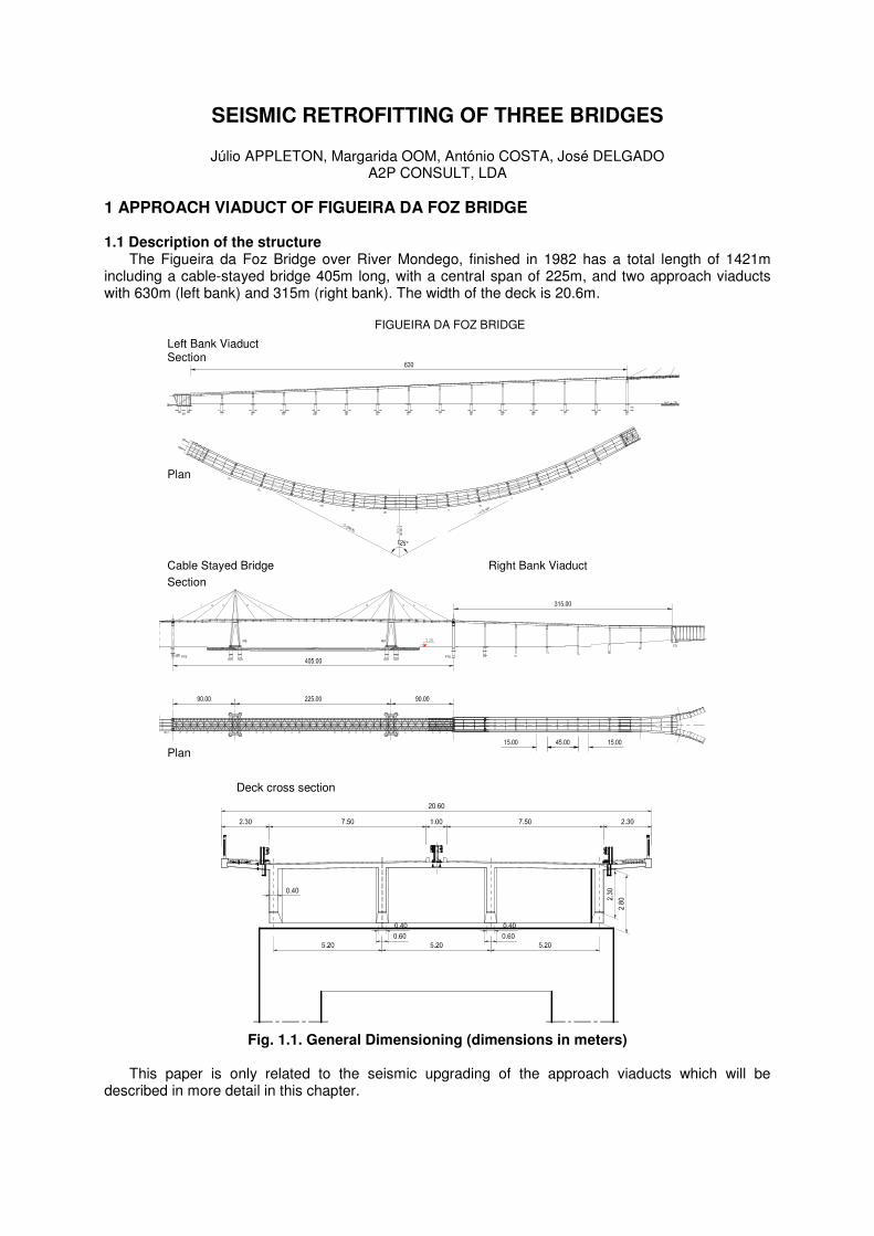
The Figueira da Foz Bridge over River Mondego, finished in 1982 has a total length of 1421m including a cable-stayed bridge 405m long, with a central span of 225m, and two approach viaducts with 630m (left bank) and 315m (right bank). The width of the deck is 20.6m.
FIGUEIRA DA FOZ BRIDGE
EE
ED
ME MD
Left Bank ViaductSection
Plan
Cable Stayed Bridge Right Bank Viaduct
Section
Plan
PTDPTE
Deck cross section
Fig. 1.1. General Dimensioning (dimensions in meters)
This paper is only related to the seismic upgrading of the approach viaducts which will be
described in more detail in this chapter.
The deck of the approach viaducts have a slab 0.18m (span) to 0.22m (over the girders) thick supported by 4 longitudinal beams, spaced 5.20m with 45.0m spans.
The prestressed concrete girders have a section of 0.40m × 2.00m at mid span and 0.60m × 2.50m at the supports. The slab is prestressed in the transverse direction. The deck is continuous for each viaduct. The girders are fixed to the transverse beams of the columns by dowels and plumb bearings. Only in the transition pier to the cable stayed bridge the support of the deck allows relative horizontal movements. The longitudinal beams are also interconnected by transverse beams spaced 15.00m.
Each support alignment has 2 hollow rectangular columns 3.00m × 1.60m connected at the top by
a hollow rectangular beam 4.00m × 1.60m, with a thickness of 0.25m. The abutments are apparent. The deck is fixed to the abutment for the left bank abutment. In this work we chose to present only the left bank viaduct.
1.2 Assessment of the seismic resistance of the existing structure A three dimensional model was used. This model showed that the design acting forces in shorter
columns exceeded its strength capacity The connection of the deck to the abutment presented two problems. The dowel bars do not have
the required strength capacity and the connection to the beam is also not robust enough to guarantee the transfer of the seismic action to the abutment. The estimated force transferred to the abutments is
11268KN and the strength capacity of 6φ40 per beam is estimated in 4m × 605KN = 2420KN. It is to be referred that an experimental evaluation of the frequencies was done in the viaduct in
order to access its behaviour and accuracy of the analytical model.
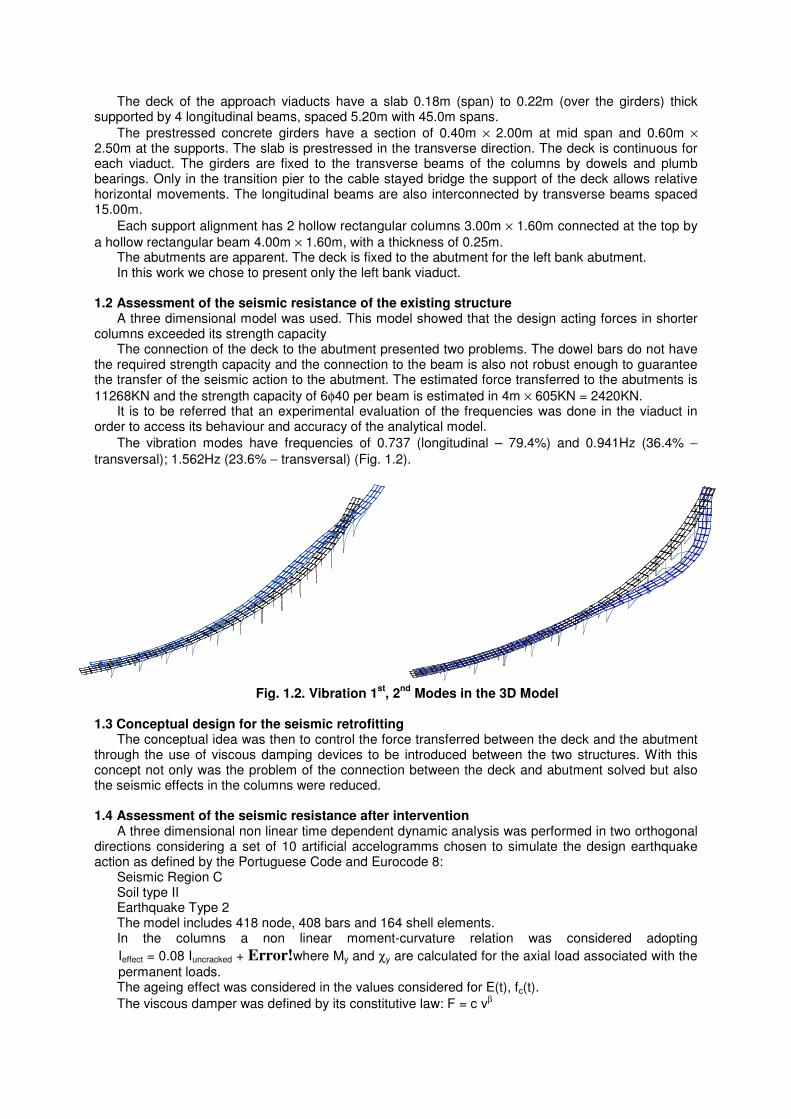
The vibration modes have frequencies of 0.737 (longitudinal – 79.4%) and 0.941Hz (36.4% −
transversal); 1.562Hz (23.6% − transversal) (Fig. 1.2).
Fig. 1.2. Vibration 1
st, 2
nd Modes in the 3D Model
1.3 Conceptual design for the seismic retrofitting
The conceptual idea was then to control the force transferred between the deck and the abutment through the use of viscous damping devices to be introduced between the two structures. With this concept not only was the problem of the connection between the deck and abutment solved but also the seismic effects in the columns were reduced.
1.4 Assessment of the seismic resistance after intervention
A three dimensional non linear time dependent dynamic analysis was performed in two orthogonal directions considering a set of 10 artificial accelogramms chosen to simulate the design earthquake action as defined by the Portuguese Code and Eurocode 8:
Seismic Region C Soil type II Earthquake Type 2 The model includes 418 node, 408 bars and 164 shell elements. In the columns a non linear moment-curvature relation was considered adopting
Ieffect = 0.08 Iuncracked + Error!where My and χy are calculated for the axial load associated with the permanent loads. The ageing effect was considered in the values considered for E(t), fc(t).
The viscous damper was defined by its constitutive law: F = c vβ
A viscous damper was considered in each of the four beams. The design parameters were
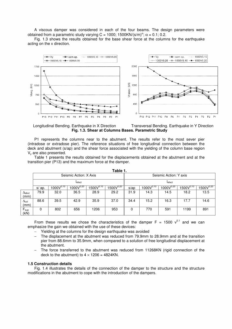
obtained from a parametric study varying C = 1000; 1500KN/(s/m)α; α = 0.1; 0.2. Fig. 1.3 shows the results obtained for the base shear force at the columns for the earthquake
acting on the x direction.
Longitudinal Bending. Earthquake in X Direction Transversal Bending. Earthquake in Y Direction Fig. 1.3. Shear at Columns Bases. Parametric Study
P1 represents the columns near to the abutment. The results refer to the most sever pier
(intradose or extradose pier). The reference situations of free longitudinal connection between the deck and abutment (s/ap) and the shear force associated with the yielding of the column base region Vy are also presented.
Table 1 presents the results obtained for the displacements obtained at the abutment and at the transition pier (P13) and the maximum force at the damper.
Table 1.
Seismic Action: X Axis Seismic Action: Y axis
lefect lefect
s/ ap. 1000V0.10
1000V0.20
1500V0.10
1500V0.20
s/ap 1000V0.10
1000V0.20
1500V0.10
1500V0.20
∆abut (mm)
79.9 32.0 36.5 28.9 29.2 31.9 14.3 14.5 18.2 13.5
∆col (mm)
88.6 39.5 42.9 35.9 37.0 34.4 15.2 16.3 17.7 14.6
Fsup (kN)
0 802 656 1206 953 0 770 591 1199 891
From these results we chose the characteristics of the damper F = 1500 v
0.1 and we can
emphasize the gain we obtained with the use of these devices:
− Yielding at the columns for the design earthquake was avoided
− The displacement at the abutment was reduced from 79.9mm to 28.9mm and at the transition pier from 88.6mm to 35.9mm, when compared to a solution of free longitudinal displacement at the abutment.
− The force transferred to the abutment was reduced from 11268KN (rigid connection of the
deck to the abutment) to 4 × 1206 = 4824KN.
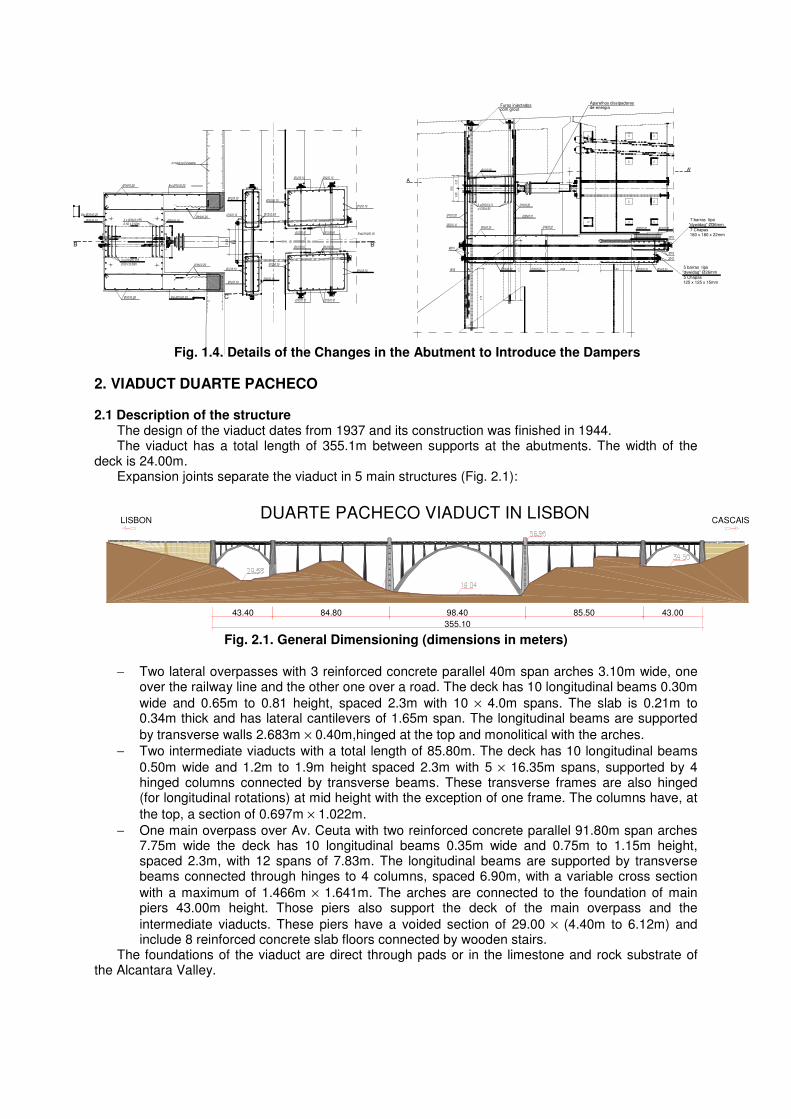
1.5 Construction details Fig. 1.4 illustrates the details of the connection of the damper to the structure and the structure
modifications in the abutment to cope with the introduction of the dampers.
B B'
C
Aparelhos dissipadoresde energia
5 Chapas125 x 125 x 15mm
5 barras tipo"dywidag" Ø26mm
7 Chapas180 x 180 x 22mm
7 barras tipo"dywidag" Ø36mm
Furos injectadoscom grout
A
A'
Fig. 1.4. Details of the Changes in the Abutment to Introduce the Dampers
2. VIADUCT DUARTE PACHECO 2.1 Description of the structure
The design of the viaduct dates from 1937 and its construction was finished in 1944. The viaduct has a total length of 355.1m between supports at the abutments. The width of the
deck is 24.00m. Expansion joints separate the viaduct in 5 main structures (Fig. 2.1):
355.10
LISBON CASCAIS
84.80 98.40 85.50 43.0043.40
DUARTE PACHECO VIADUCT IN LISBON
Fig. 2.1. General Dimensioning (dimensions in meters)
− Two lateral overpasses with 3 reinforced concrete parallel 40m span arches 3.10m wide, one over the railway line and the other one over a road. The deck has 10 longitudinal beams 0.30m
wide and 0.65m to 0.81 height, spaced 2.3m with 10 × 4.0m spans. The slab is 0.21m to 0.34m thick and has lateral cantilevers of 1.65m span. The longitudinal beams are supported
by transverse walls 2.683m × 0.40m,hinged at the top and monolitical with the arches.
− Two intermediate viaducts with a total length of 85.80m. The deck has 10 longitudinal beams
0.50m wide and 1.2m to 1.9m height spaced 2.3m with 5 × 16.35m spans, supported by 4 hinged columns connected by transverse beams. These transverse frames are also hinged (for longitudinal rotations) at mid height with the exception of one frame. The columns have, at
the top, a section of 0.697m × 1.022m.
− One main overpass over Av. Ceuta with two reinforced concrete parallel 91.80m span arches 7.75m wide the deck has 10 longitudinal beams 0.35m wide and 0.75m to 1.15m height, spaced 2.3m, with 12 spans of 7.83m. The longitudinal beams are supported by transverse beams connected through hinges to 4 columns, spaced 6.90m, with a variable cross section
with a maximum of 1.466m × 1.641m. The arches are connected to the foundation of main piers 43.00m height. Those piers also support the deck of the main overpass and the
intermediate viaducts. These piers have a voided section of 29.00 × (4.40m to 6.12m) and include 8 reinforced concrete slab floors connected by wooden stairs.
The foundations of the viaduct are direct through pads or in the limestone and rock substrate of the Alcantara Valley.
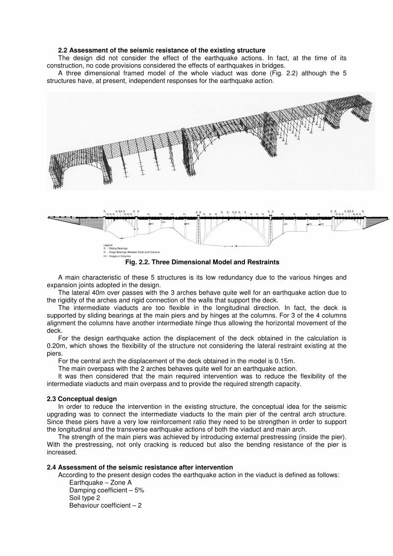
2.2 Assessment of the seismic resistance of the existing structure The design did not consider the effect of the earthquake actions. In fact, at the time of its
construction, no code provisions considered the effects of earthquakes in bridges. A three dimensional framed model of the whole viaduct was done (Fig. 2.2) although the 5
structures have, at present, independent responses for the earthquake action.
HS
H HS SS
H H HS S
H H H HS S
H H HS S SS S S
H H HS S
H H H HS S
H H HS SS
H H HSS
H1H1
H1 H1 H1 H1
S
S - Sliding Bearings
H - Hinge Bearings Between Deck and Columns
H1- Hinges in Columns
Legend:
Fig. 2.2. Three Dimensional Model and Restraints
A main characteristic of these 5 structures is its low redundancy due to the various hinges and
expansion joints adopted in the design. The lateral 40m over passes with the 3 arches behave quite well for an earthquake action due to
the rigidity of the arches and rigid connection of the walls that support the deck. The intermediate viaducts are too flexible in the longitudinal direction. In fact, the deck is
supported by sliding bearings at the main piers and by hinges at the columns. For 3 of the 4 columns alignment the columns have another intermediate hinge thus allowing the horizontal movement of the deck.
For the design earthquake action the displacement of the deck obtained in the calculation is 0.20m, which shows the flexibility of the structure not considering the lateral restraint existing at the piers.
For the central arch the displacement of the deck obtained in the model is 0.15m. The main overpass with the 2 arches behaves quite well for an earthquake action. It was then considered that the main required intervention was to reduce the flexibility of the
intermediate viaducts and main overpass and to provide the required strength capacity.
2.3 Conceptual design In order to reduce the intervention in the existing structure, the conceptual idea for the seismic
upgrading was to connect the intermediate viaducts to the main pier of the central arch structure. Since these piers have a very low reinforcement ratio they need to be strengthen in order to support the longitudinal and the transverse earthquake actions of both the viaduct and main arch.
The strength of the main piers was achieved by introducing external prestressing (inside the pier). With the prestressing, not only cracking is reduced but also the bending resistance of the pier is increased.
2.4 Assessment of the seismic resistance after intervention
According to the present design codes the earthquake action in the viaduct is defined as follows: Earthquake – Zone A Damping coefficient – 5% Soil type 2 Behaviour coefficient – 2
E'c = 1.25 EC,28 Considering the rigid connection between the intermediate viaduct and the central arch the mode
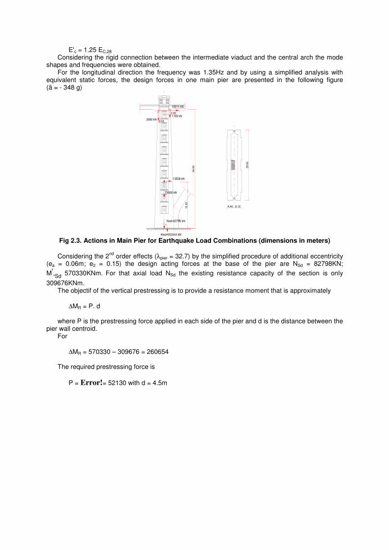
shapes and frequencies were obtained. For the longitudinal direction the frequency was 1.35Hz and by using a simplified analysis with
equivalent static forces, the design forces in one main pier are presented in the following figure (ä = - 348 g)
15
.50
2.00
2.00
29.0
0
4.40 - 6.12
34
.00
Fig 2.3. Actions in Main Pier for Earthquake Load Combinations (dimensions in meters)
Considering the 2nd
order effects (λpier = 32.7) by the simplified procedure of additional eccentricity (ea = 0.06m; e2 = 0.15) the design acting forces at the base of the pier are NSd = 82798KN;
M',Sd
570330KNm. For that axial load NSd the existing resistance capacity of the section is only
309676KNm. The objectif of the vertical prestressing is to provide a resistance moment that is approximately
∆MR = P. d where P is the prestressing force applied in each side of the pier and d is the distance between the
pier wall centroid. For
∆MR = 570330 – 309676 = 260654 The required prestressing force is
P = Error!= 52130 with d = 4.5m
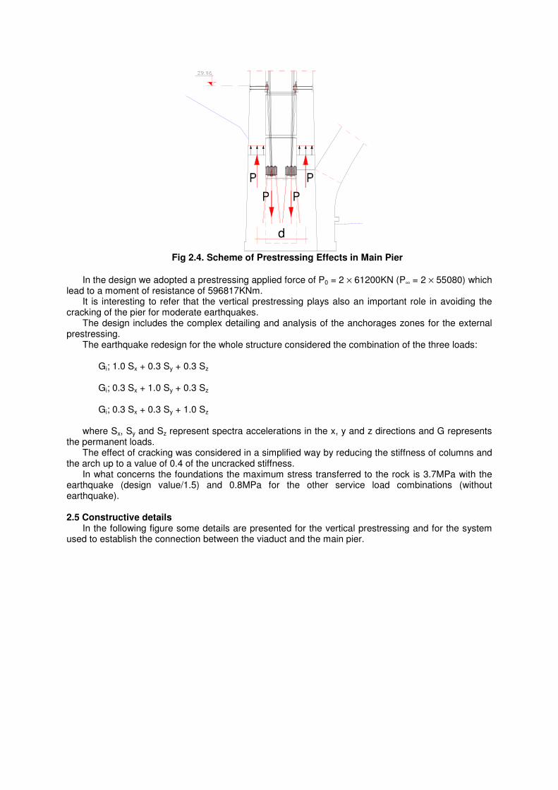
d
Fig 2.4. Scheme of Prestressing Effects in Main Pier
In the design we adopted a prestressing applied force of P0 = 2 × 61200KN (P∞ = 2 × 55080) which lead to a moment of resistance of 596817KNm.
It is interesting to refer that the vertical prestressing plays also an important role in avoiding the cracking of the pier for moderate earthquakes.
The design includes the complex detailing and analysis of the anchorages zones for the external prestressing.
The earthquake redesign for the whole structure considered the combination of the three loads: Gi; 1.0 Sx + 0.3 Sy + 0.3 Sz Gi; 0.3 Sx + 1.0 Sy + 0.3 Sz Gi; 0.3 Sx + 0.3 Sy + 1.0 Sz where Sx, Sy and Sz represent spectra accelerations in the x, y and z directions and G represents
the permanent loads. The effect of cracking was considered in a simplified way by reducing the stiffness of columns and
the arch up to a value of 0.4 of the uncracked stiffness. In what concerns the foundations the maximum stress transferred to the rock is 3.7MPa with the
earthquake (design value/1.5) and 0.8MPa for the other service load combinations (without earthquake).
2.5 Constructive details
In the following figure some details are presented for the vertical prestressing and for the system used to establish the connection between the viaduct and the main pier.
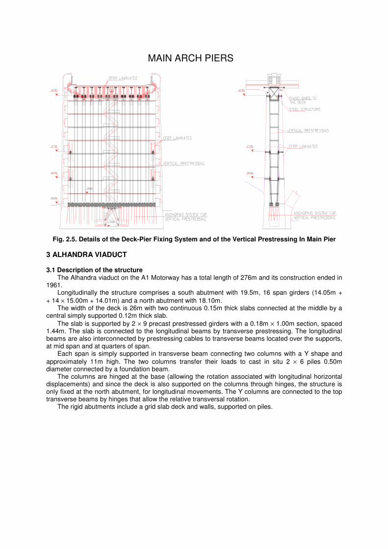
MAIN ARCH PIERS
Fig. 2.5. Details of the Deck-Pier Fixing System and of the Vertical Prestressing In Main Pier
3 ALHANDRA VIADUCT
3.1 Description of the structure The Alhandra viaduct on the A1 Motorway has a total length of 276m and its construction ended in
1961. Longitudinally the structure comprises a south abutment with 19.5m, 16 span girders (14.05m +
+ 14 × 15.00m + 14.01m) and a north abutment with 18.10m. The width of the deck is 26m with two continuous 0.15m thick slabs connected at the middle by a
central simply supported 0.12m thick slab.
The slab is supported by 2 × 9 precast prestressed girders with a 0.18m × 1.00m section, spaced 1.44m. The slab is connected to the longitudinal beams by transverse prestressing. The longitudinal beams are also interconnected by prestressing cables to transverse beams located over the supports, at mid span and at quarters of span.
Each span is simply supported in transverse beam connecting two columns with a Y shape and
approximately 11m high. The two columns transfer their loads to cast in situ 2 × 6 piles 0.50m diameter connected by a foundation beam.
The columns are hinged at the base (allowing the rotation associated with longitudinal horizontal displacements) and since the deck is also supported on the columns through hinges, the structure is only fixed at the north abutment, for longitudinal movements. The Y columns are connected to the top transverse beams by hinges that allow the relative transversal rotation.
The rigid abutments include a grid slab deck and walls, supported on piles.
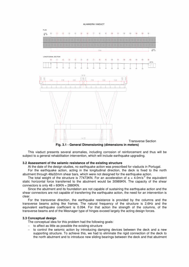
PLAN
ALHANDRA VIADUCT
LONGITUDINAL SECTION
DETAIL
1 2 3 4 5 6 7 8 9 10 11 12 13 14 15
821S 543 76 1411109 1312 N15
LISBOA S N
PORTO
Transverse Section Fig. 3.1 - General Dimensioning (dimensions in meters)
This viaduct presents several anomalies, including corrosion of reinforcement and thus will be
subject to a general rehabilitation intervention, which will include earthquake upgrading.
3.2 Assessment of the seismic resistance of the existing structure At the date of the design studies, no earthquake action was prescribed for viaducts in Portugal. For the earthquake action, acting in the longitudinal direction, the deck is fixed to the north
abutment through 48φ32mm shear bars, which were not designed for the earthquake action. The total weight of the structure is 77473KN. For an acceleration of a = 4.0m/s
-2 the equivalent
static horizontal force transferred to the abutment would be 30989KN. The capacity of the shear
connectors is only 48 × 60KN = 2880KN. Since the abutment and its foundation are not capable of sustaining the earthquake action and the
shear connectors are not capable of transferring the earthquake action, the need for an intervention is clear.
For the transverse direction, the earthquake resistance is provided by the columns and the transverse beams acting like frames. The natural frequency of the structure is 2.6Hz and the equivalent earthquake coefficient is 0.094. For that action the strength of the columns, of the transverse beams and of the Mesnager type of hinges exceed largely the acting design forces.
3.3 Conceptual design
The conceptual idea for this problem had the following goals:
− to affect as little as possible the existing structure
− to control the seismic action by introducing damping devices between the deck and a new supporting structure. To achieve this, we had to eliminate the rigid connection of the deck to the north abutment and to introduce new sliding bearings between the deck and that abutment
and to redesign the expansion joint. We also had to design a new supporting steel structure and its foundations.
3.4 Assessment of seismic resistance after the intervention
The intervention consists in the introduction of 4 viscous damping devices connecting the existing deck to a new steel structure, to be executed near the north abutment, supported by new pile foundations.
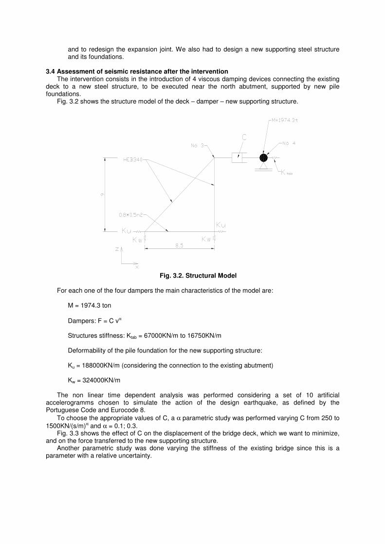
Fig. 3.2 shows the structure model of the deck – damper – new supporting structure.
Fig. 3.2. Structural Model
For each one of the four dampers the main characteristics of the model are: M = 1974.3 ton
Dampers: F = C vα Structures stiffness: Ktab = 67000KN/m to 16750KN/m Deformability of the pile foundation for the new supporting structure: Ku = 188000KN/m (considering the connection to the existing abutment) Kw = 324000KN/m The non linear time dependent analysis was performed considering a set of 10 artificial
accelerogramms chosen to simulate the action of the design earthquake, as defined by the Portuguese Code and Eurocode 8.
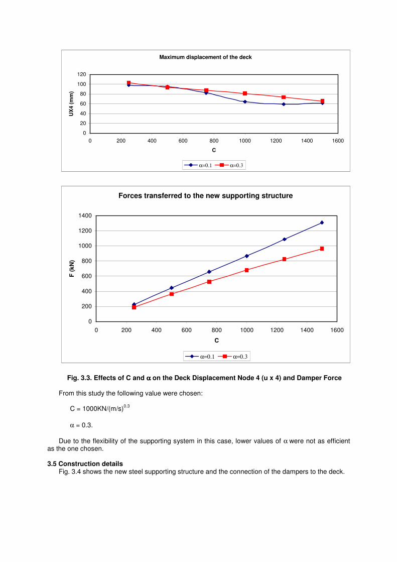
To choose the appropriate values of C, a α parametric study was performed varying C from 250 to
1500KN/(s/m)α and α = 0.1; 0.3. Fig. 3.3 shows the effect of C on the displacement of the bridge deck, which we want to minimize,
and on the force transferred to the new supporting structure. Another parametric study was done varying the stiffness of the existing bridge since this is a
parameter with a relative uncertainty.
Maximum displacement of the deck
0
20
40
60
80
100
120
0 200 400 600 800 1000 1200 1400 1600
C
UX
4 (
mm
)
α=0.1 α=0.3
Forces transferred to the new supporting structure
0
200
400
600
800
1000
1200
1400
0 200 400 600 800 1000 1200 1400 1600
C
F (
kN
)
α=0.1 α=0.3
Fig. 3.3. Effects of C and αααα on the Deck Displacement Node 4 (u x 4) and Damper Force From this study the following value were chosen: C = 1000KN/(m/s)
0.3
α = 0.3.
Due to the flexibility of the supporting system in this case, lower values of α were not as efficient as the one chosen.
3.5 Construction details
Fig. 3.4 shows the new steel supporting structure and the connection of the dampers to the deck.
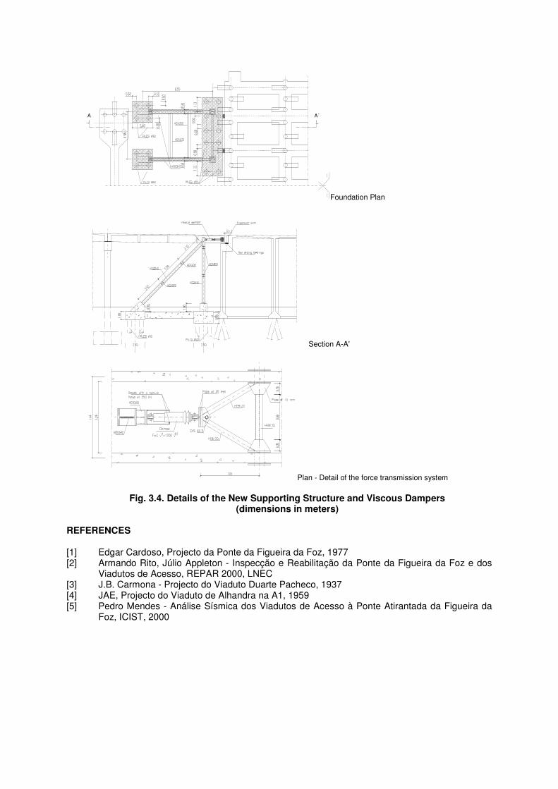
A A´
Foundation Plan
Section A-A'
Plan - Detail of the force transmission system
Fig. 3.4. Details of the New Supporting Structure and Viscous Dampers (dimensions in meters)
REFERENCES
[1] Edgar Cardoso, Projecto da Ponte da Figueira da Foz, 1977 [2] Armando Rito, Júlio Appleton - Inspecção e Reabilitação da Ponte da Figueira da Foz e dos
Viadutos de Acesso, REPAR 2000, LNEC [3] J.B. Carmona - Projecto do Viaduto Duarte Pacheco, 1937 [4] JAE, Projecto do Viaduto de Alhandra na A1, 1959 [5] Pedro Mendes - Análise Sísmica dos Viadutos de Acesso à Ponte Atirantada da Figueira da
Foz, ICIST, 2000