security analysis of a software defined wide area network...
TRANSCRIPT
IN DEGREE PROJECT ELECTRICAL ENGINEERING,SECOND CYCLE, 30 CREDITS
, STOCKHOLM SWEDEN 2016
Security Analysis of a Software Defined Wide Area Network Solution
ASHOK RAJENDRAN
KTH ROYAL INSTITUTE OF TECHNOLOGYSCHOOL OF INFORMATION AND COMMUNICATION TECHNOLOGY
Aalto University
School of Science
Degree Programme in Security and Mobile Computing
Ashok Rajendran
Security Analysis of a Software DefinedWide Area Network Solution
Master’s ThesisEspoo, July 13, 2016
Supervisors: Professor Tuomas Aura, Aalto UniversityProfessor Markus Hidell, KTH Royal Institute of Technology
Advisor: Pekka Isomaki, M.Sc. (Tech.)
Aalto UniversitySchool of ScienceDegree Programme in Security and Mobile Computing
ABSTRACT OFMASTER’S THESIS
Author: Ashok Rajendran
Title:Security Analysis of a Software Defined Wide Area Network Solution
Date: July 13, 2016 Pages: 71
Major: Data Communication Software Code: T-110
Supervisors: Professor Tuomas AuraProfessor Markus Hidell
Advisor: Pekka Isomaki, M.Sc. (Tech.)
Enterprise wide area network (WAN) is a private network that connects the com-puters and other devices across an organisation’s branch locations and the datacenters. It forms the backbone of enterprise communication. Currently, multi-protocol label switching (MPLS) is commonly used to provide this service. Asa recent alternative to MPLS, software-defined wide area networking (SD-WAN)solutions are being introduced as an IP based cloud-networking service for en-terprises. SD-WAN virtualizes the networking service and eases the complexityof configuring and managing the enterprise network by moving these tasks tosoftware and a central controller. The introduction of new technologies causesconcerns about their security. Also, this new solution is introduced as a replace-ment for MPLS, which has been considered secure and has been in use for morethan 16 years. Thus, there is a need to analyze the security of SD-WAN, whichis the goal of this thesis.
In this thesis, we perform a security analysis of a commercial SD-WAN solu-tion, by finding its various attack surfaces, associated vulnerabilities and designweaknesses. We choose Nuage VNS, an SD-WAN product provided by NuageNetworks, as the analysis target. As a result, many attack surfaces and secu-rity weaknesses were found and reported, especially in the Customer PremisesEquipment (CPE). In particular, we found vulnerabilities in the CPE’s securebootstrapping method and demonstrated some attacks by exploiting them. Fi-nally, we propose mitigation steps to avoid the attacks.
The results of this thesis will help both the service provider and the SD-WANsolution vendor to know about the attack surfaces and weaknesses of SD-WANbefore offering it to their customers. We also help in implementing the temporarycountermeasures to mitigate the attacks. The results have been presented to theservice provider and the vendor of the SD-WAN product.
Keywords: SD-WAN, Nuage VNS, virtual network functions, securityanalysis, VXLAN, SDN overlay, man-in-the-middle attack,API access control
Language: English
2
Aalto-universitetetHogskolan for teknikvetenskaperExamensprogram for datateknik
SAMMANDRAG AVDIPLOMARBETET
Utfort av: Ashok Rajendran
Arbetets namn:Sakerhet Analys av Software Defined Wide Area Network Losning
Datum: Juli 13, 2016 Sidantal: 71
Huvudamne: Datakommunikationsprogram Kod: T-110
overvakare: Professor Tuomas AuraProfessor Markus Hidell
Handledare: Pekka Isomaki, M.Sc. (Tech.)
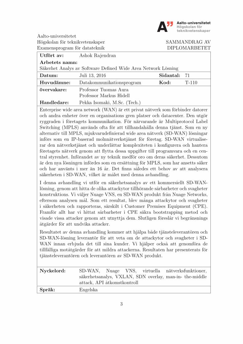
Enterprise wide area network (WAN) ar ett privat natverk som forbinder datoreroch andra enheter over en organisations gren platser och datacenter. Den utgorryggraden i foretagets kommunikation. For narvarande ar Multiprotocol LabelSwitching (MPLS) anvands ofta for att tillhandahalla denna tjanst. Som en nyalternativ till MPLS, mjukvarudefinierad wide area natverk (SD-WAN) losningarinfors som en IP-baserad molnnatverkstjanst for foretag. SD-WAN virtualise-rar den natverkstjanst och underlattar komplexiteten i konfigurera och hanteraforetagets natverk genom att flytta dessa uppgifter till programvara och en cen-tral styrenhet. Inforandet av ny teknik medfor oro om deras sakerhet. Dessutomar den nya losningen infordes som en ersattning for MPLS, som har ansetts sakeroch har anvants i mer an 16 ar. Det finns saledes ett behov av att analyserasakerheten i SD-WAN, vilket ar malet med denna avhandling.
I denna avhandling vi utfor en sakerhetsanalys av ett kommersiellt SD-WAN-losning, genom att hitta de olika attackytor tillhorande sarbarheter och svagheterkonstruktions. Vi valjer Nuage VNS, en SD-WAN produkt fran Nuage Networks,eftersom analysen mal. Som ett resultat, blev manga attackytor och svagheteri sakerheten och rapporteras, sarskilt i Customer Premises Equipment (CPE).Framfor allt har vi hittat sarbarheter i CPE sakra bootstrapping metod ochvisade vissa attacker genom att utnyttja dem. Slutligen foreslar vi begransningsatgarder for att undvika attacker.
Resultatet av denna avhandling kommer att hjalpa bade tjansteleverantoren ochSD-WAN-losning leverantor for att veta om de attackytor och svagheter i SD-WAN innan erbjuda det till sina kunder. Vi hjalper ocksa att genomfora detillfalliga motatgarder for att mildra attackerna. Resultaten har presenterats fortjansteleverantoren och leverantoren av SD-WAN produkt.
Nyckelord: SD-WAN, Nuage VNS, virtuella natverksfunktioner,sakerhetsanalys, VXLAN, SDN overlay, man-in- the-middleattack, API atkomstkontroll
Sprak: Engelska
3
Acknowledgements
First, I want to thank my supervisor, Prof. Tuomas Aura for his guidancethroughout my thesis work. I am thankful for the time he has spent ondiscussing my topic and on guiding my work. I am grateful to my instructors,Mr. Isomaki Pekka and Mr. Janne Mikola from Sonera for providing me achance to work on the latest technology for my thesis and also helping me inunderstanding the new concepts.
I would also like to thank my supervisor, Prof. Markus Hidell for provid-ing me a remote support for finishing my thesis. Finally, I would like to adda word of gratitude to my friends and family for supporting me throughoutmy master study.
Espoo, July 13, 2016
Ashok Rajendran
4
Abbreviations and Acronyms
SD-WAN Software Defined Wide Area NetworkSDN Software Defined NetworkingNFV Network Function VirtualisationNV Network virtualisationVNS Virtualised Networking ServicesVXLAN Virtual Extensible Local Area NetworkMPLS Multiprotocol Label SwitchingCPE Customer Premises EquipmentVPN Virtual Private NetworkIPsec Internet Protocol SecurityATM Asynchronous Transfer ModeDSL Digital Subscriber LineIETF Internet Engineering Task ForceWAN Wide Area NetworkLAN Local Area NetworkOPEX Operational ExpenditureNAT Network Address TranslationVLAN Virtual Local Area NetworkGRE Generic Routing EncapsulationONUG Open Networking User GroupPKI Public Key InfrastructureCA Certification AuthorityAPI Application Program InterfaceNSG Network Services GatewayVSC Virtualized Services ControllerVSD Virtualized Services DirectoryVSP Virtualized Services PlatformDNS Domain Name SystemDHCP Dynamic Host Configuration ProtocolXMPP Extensible Messaging and Presence Protocol
5
MP-BGP Multiprotocol Border Gateway ProtocolSMS Short Message ServiceSMTP Simple Mail Transfer ProtocolOF-TLS OpenFlow over Transport Layer SecurityHTTPS Hypertext Transfer Protocol secureXML Extensible Markup LanguageSSH Secure ShellTLS Transport Layer SecuritySNMP Simple Network Management ProtocolTEK Traffic Encryption KeyNTP Network Time ProtocolSEK Seed Encryption KeyAES CBC Advanced Encryption Standard cipher block chainingHMAC Hash-based message authentication codesGUI Graphical User InterfaceTCP Transmission Control ProtocolSS7 Signalling System No. 7SSL Secure Sockets LayerCSR Certificate signing requestMITM Man-in-the-middleDOS Denial of ServiceTPM Trusted Platform ModuleEK Endorsement KeySRK Storage Root KeySHA-1 Secure Hash Algorithm 1RSA Ron Rivest, Adi Shamir and Leonard Adleman Algo-
rithmBGP Border Gateway ProtocolAAA Authentication, Authorization and AccountingUID Unique Identification NumberXMPP-TLS Extensible Messaging and Presence Protocol over
Transport Layer Security
6
Contents
Abbreviations and Acronyms 5
1 Introduction 9
2 Background 132.1 Enterprise networks . . . . . . . . . . . . . . . . . . . . . . . . 132.2 Existing MPLS-based networking solution . . . . . . . . . . . 142.3 Problems faced with MPLS . . . . . . . . . . . . . . . . . . . 152.4 Cutting-edge technologies . . . . . . . . . . . . . . . . . . . . 162.5 SD-WAN solution . . . . . . . . . . . . . . . . . . . . . . . . . 192.6 Need for security analysis of SD-WAN solution . . . . . . . . . 202.7 Related literature . . . . . . . . . . . . . . . . . . . . . . . . . 22
3 Case study:Nuage VNS solution 243.1 Nuage VNS architecture . . . . . . . . . . . . . . . . . . . . . 24
3.1.1 Nuage VNS operation . . . . . . . . . . . . . . . . . . 273.2 Nuage VNS security features . . . . . . . . . . . . . . . . . . . 28
3.2.1 Interfaces of Nuage VNS . . . . . . . . . . . . . . . . . 283.2.2 NSG and the bootstrapping process . . . . . . . . . . . 303.2.3 Control plane security: VSC security . . . . . . . . . . 323.2.4 IPsec key rotation method . . . . . . . . . . . . . . . . 32
4 Vulnerabilities and attack scenarios 354.1 Analysis of NSG attack surfaces . . . . . . . . . . . . . . . . . 354.2 Basic vulnerabilities . . . . . . . . . . . . . . . . . . . . . . . . 38
4.2.1 Vulnerability 1: open SSH port . . . . . . . . . . . . . 384.2.2 Vulnerability 2: open HTTP port . . . . . . . . . . . . 404.2.3 Vulnerability 3: activation e-mail . . . . . . . . . . . . 40
4.3 Attacks against the NSG bootstrapping process . . . . . . . . 434.3.1 NSG bootstrapping process . . . . . . . . . . . . . . . 444.3.2 Man-in-the-middle attack . . . . . . . . . . . . . . . . 47
7
4.3.3 Insufficient access control to APIs . . . . . . . . . . . . 494.3.4 Other attacks . . . . . . . . . . . . . . . . . . . . . . . 53
5 Discussion 545.1 Solutions for the attacks . . . . . . . . . . . . . . . . . . . . . 54
5.1.1 Minimizing NSG’s attack surface . . . . . . . . . . . . 545.1.2 Replacing the bootstrap CA certificates . . . . . . . . . 555.1.3 Adding secure access control at the proxy . . . . . . . 55
5.2 General discussion . . . . . . . . . . . . . . . . . . . . . . . . 565.2.1 TPM . . . . . . . . . . . . . . . . . . . . . . . . . . . . 56
5.3 Future work . . . . . . . . . . . . . . . . . . . . . . . . . . . . 57
6 Conclusions 59
A Accessible APIs 66
B Client certificate authentication 68
C Snapshots of the MITM tool 70
8
Chapter 1
Introduction
Enterprise networks form the backbone of everyday communication that con-nect computers and other devices across different company branches includ-ing data centers. These networks allow users and devices in the enterprisenetwork to share data in a secure way. Such enterprise networks may includeWide Area Networks (WAN) and Local Area Networks (LAN), depending onthe organization structure and operational requirements. In the early days,point-to-point leased lines were used to provide enterprise network solutionswith dedicated DS0 and T1/E1 or T3/E3 connections [10]. In the 90s, thiswas replaced by the less expensive frame relay service, which required fewerphysical connections. Thus, this technology was widely accepted by manyenterprises including banks. MPLS is the successor to the frame relay service.It was designed as an IP based solution to use the infrastructure of a telecomnetwork. Hence, telecom service providers prefer the MPLS based solutionover the frame relay service to offer for their customers. For instance, Son-era, a leading telecom operator in Finland, currently offers an MPLS solutioncalled as Sonera Datanet, and it is a market leader in Finland.
In spite of having been adopted by many enterprises, MPLS has its draw-backs in terms of cost and bandwidth. MPLS connections remain expensiveand offer low bandwith compared to the public internet. Moreover, the in-troduction of technologies such as IPsec VPN allows sharing of enterprisedata over the public internet in a secure way. Considering the above fac-tors, enterprises started to look for alternative solutions to MPLS. On theother hand, service providers also face problems in providing MPLS to thenew generation enterprises which have started to rely on public clouds fortheir infrastructure. MPLS has problems in connecting the enterprise branchsites to the public clouds operated in third-party data centers. Due to thisbusiness shift, Sonera has started to see a decline in revenue in its MPLSbusiness recently. Consequently, there is a need for both enterprises and
9
CHAPTER 1. INTRODUCTION 10
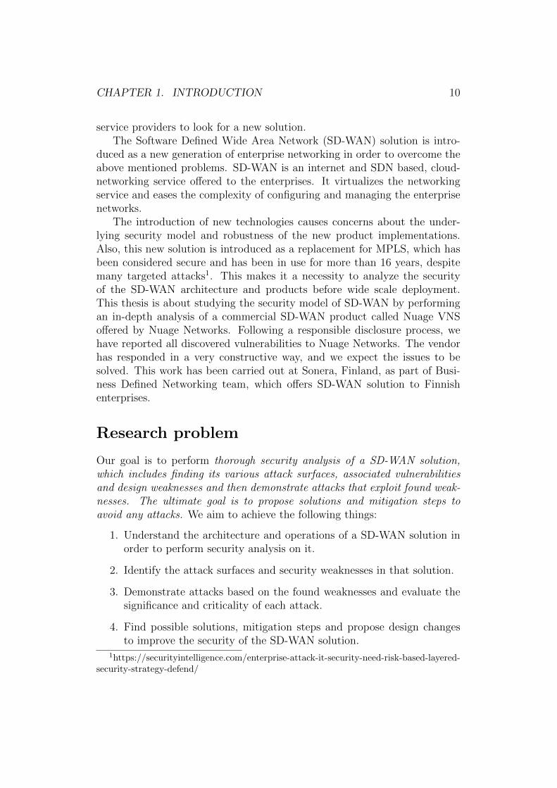
service providers to look for a new solution.The Software Defined Wide Area Network (SD-WAN) solution is intro-
duced as a new generation of enterprise networking in order to overcome theabove mentioned problems. SD-WAN is an internet and SDN based, cloud-networking service offered to the enterprises. It virtualizes the networkingservice and eases the complexity of configuring and managing the enterprisenetworks.
The introduction of new technologies causes concerns about the under-lying security model and robustness of the new product implementations.Also, this new solution is introduced as a replacement for MPLS, which hasbeen considered secure and has been in use for more than 16 years, despitemany targeted attacks1. This makes it a necessity to analyze the securityof the SD-WAN architecture and products before wide scale deployment.This thesis is about studying the security model of SD-WAN by performingan in-depth analysis of a commercial SD-WAN product called Nuage VNSoffered by Nuage Networks. Following a responsible disclosure process, wehave reported all discovered vulnerabilities to Nuage Networks. The vendorhas responded in a very constructive way, and we expect the issues to besolved. This work has been carried out at Sonera, Finland, as part of Busi-ness Defined Networking team, which offers SD-WAN solution to Finnishenterprises.
Research problem
Our goal is to perform thorough security analysis of a SD-WAN solution,which includes finding its various attack surfaces, associated vulnerabilitiesand design weaknesses and then demonstrate attacks that exploit found weak-nesses. The ultimate goal is to propose solutions and mitigation steps toavoid any attacks. We aim to achieve the following things:
1. Understand the architecture and operations of a SD-WAN solution inorder to perform security analysis on it.
2. Identify the attack surfaces and security weaknesses in that solution.
3. Demonstrate attacks based on the found weaknesses and evaluate thesignificance and criticality of each attack.
4. Find possible solutions, mitigation steps and propose design changesto improve the security of the SD-WAN solution.
1https://securityintelligence.com/enterprise-attack-it-security-need-risk-based-layered-security-strategy-defend/
CHAPTER 1. INTRODUCTION 11
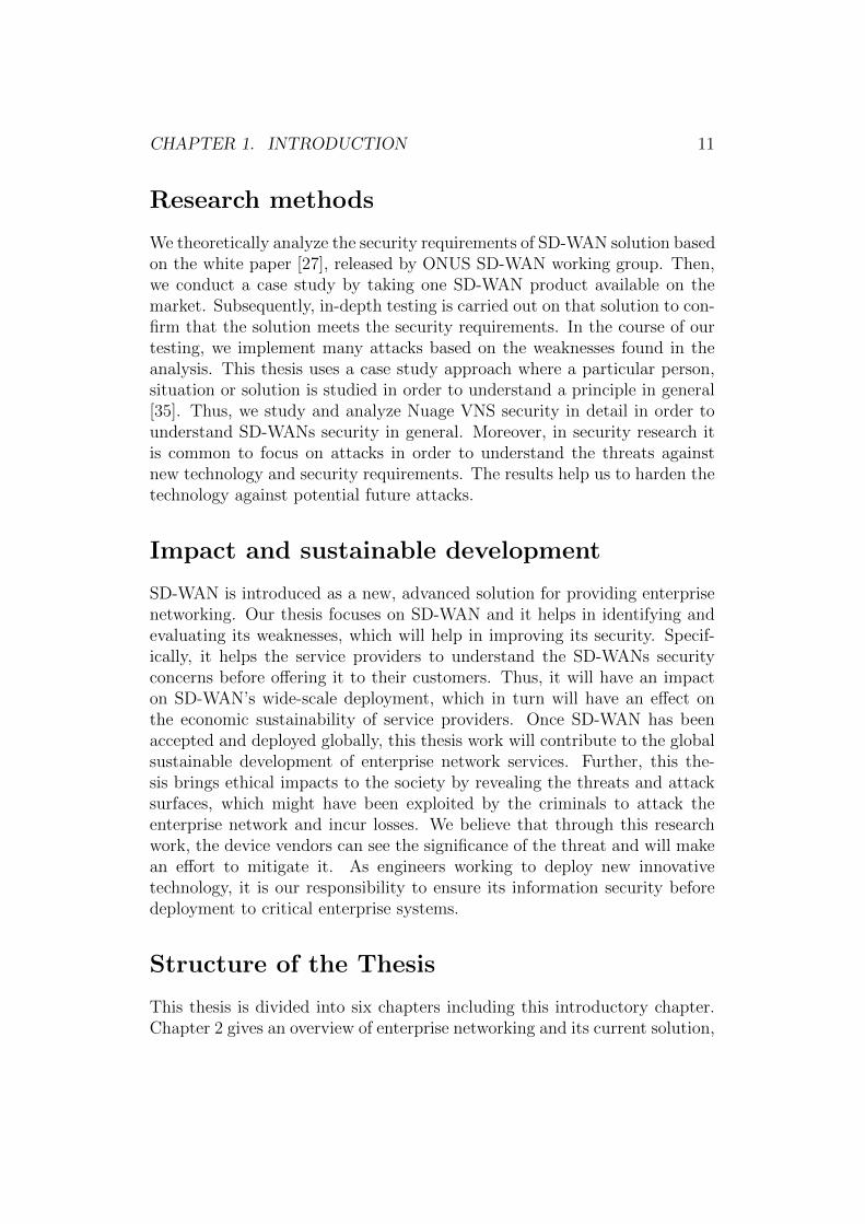
Research methods
We theoretically analyze the security requirements of SD-WAN solution basedon the white paper [27], released by ONUS SD-WAN working group. Then,we conduct a case study by taking one SD-WAN product available on themarket. Subsequently, in-depth testing is carried out on that solution to con-firm that the solution meets the security requirements. In the course of ourtesting, we implement many attacks based on the weaknesses found in theanalysis. This thesis uses a case study approach where a particular person,situation or solution is studied in order to understand a principle in general[35]. Thus, we study and analyze Nuage VNS security in detail in order tounderstand SD-WANs security in general. Moreover, in security research itis common to focus on attacks in order to understand the threats againstnew technology and security requirements. The results help us to harden thetechnology against potential future attacks.
Impact and sustainable development
SD-WAN is introduced as a new, advanced solution for providing enterprisenetworking. Our thesis focuses on SD-WAN and it helps in identifying andevaluating its weaknesses, which will help in improving its security. Specif-ically, it helps the service providers to understand the SD-WANs securityconcerns before offering it to their customers. Thus, it will have an impacton SD-WAN’s wide-scale deployment, which in turn will have an effect onthe economic sustainability of service providers. Once SD-WAN has beenaccepted and deployed globally, this thesis work will contribute to the globalsustainable development of enterprise network services. Further, this the-sis brings ethical impacts to the society by revealing the threats and attacksurfaces, which might have been exploited by the criminals to attack theenterprise network and incur losses. We believe that through this researchwork, the device vendors can see the significance of the threat and will makean effort to mitigate it. As engineers working to deploy new innovativetechnology, it is our responsibility to ensure its information security beforedeployment to critical enterprise systems.
Structure of the Thesis
This thesis is divided into six chapters including this introductory chapter.Chapter 2 gives an overview of enterprise networking and its current solution,
CHAPTER 1. INTRODUCTION 12
MPLS along with its disadvantages. Then, the architecture and working of anSD-WAN solution is discussed. Finally, we list the related literature, whichis used as a starting point for our security analysis. Chapter 3 introduces theSD-WAN product, Nuage VNS, offered by the Nuage Networks. We studyits architecture and operation in this chapter. Further, we also look intothe available security features in Nuage VNS and discuss the results of ouranalysis on them. Chapter 4 presents the vulnerabilities found in the NuageVNS in our detailed analysis. We exploited some of the weaknesses and per-formed attacks on Nuage VNS, which is also explained in detail. In chapter5, we explain the mitigation steps to avoid the attacks and, in addition, wediscuss the need for changes in the design which will prevent the attacks onSD-WAN in the future. Finally, the concluding section summarizes the keyfindings of the thesis.
Chapter 2
Background
This chapter gives an overview of enterprise networking history and its ex-isting solutions, along with the drawbacks. Here, we also discuss about theinnovative networking technologies that are used in a new alternative, SD-WAN. The SD-WAN architecture and its benefit as an enterprise networkingsolution are discussed, as well as the necessity for security analysis of SD-WAN solutions. Finally, we provide a brief overview of the literature used asreference for performing the analysis.
2.1 Enterprise networks
Enterprise network is a private network to connect an organization’s branchessecurely for sharing computer resources. The company branches may includecompany sites, stores, headquarters, and cloud data centers. The enterprisenetwork also forms a communication backbone by integrating all computers,mobiles and other associated devices of an organization. Further, it facilitatesinteroperability of all these devices within the network. It also improvesenterprise data management1.
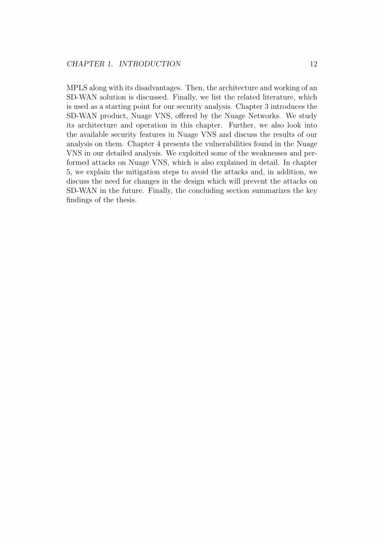
An enterprise network can be both local area network (LAN) and widearea network (WAN). Figure 2.1 shows a simple enterprise network with itsheadquarters, branches and data center connected. Traditionally, enterprisenetworks used the same telecom networks as voice communication, with verylow bandwidth modems to transmit data. However, with the digitizationand public internet usage from the 1990s, enterprises started to use virtualprivate networks that are built over the existing public infrastructure and addencryption to protect the data traffic from eavesdropping. Initially, virtualprivate network used the frame relay service [10] for providing a private
1https://www.techopedia.com/definition/7044/enterprise-network
13
CHAPTER 2. BACKGROUND 14
Figure 2.1: Enterprise Network [28]
network. Later, it has been replaced by the MPLS protocol, which is widelyaccepted and used by all the enterprise networks now.
2.2 Existing MPLS-based networking solution
Enterprise networks started to use the MPLS protocol for their private net-work from the middle of 2000s. The MPLS protocol increases data speedover the network and improves network’s performance. Traditionally, net-work packets are routed to their destination by routers based on packet’snetwork layer header. A router analyses the IP header and decides whereto forward the packet next. Thus, the routing decision is performed at layer3 of network. With MPLS, the routing decision is made based on assignedlabels instead of the IP header. Labels are added to a data packet by aingress router as it is forwarded to the operator network. Routers analysethe labels and forward the packet to the next router. They do not spendtime on analyzing the IP header. Routers usually have set of rules statingwhere to forward the packets based on their labels. Labels are in the MPLSheader, which are prefixed before the IP header. A sample MPLS network
CHAPTER 2. BACKGROUND 15
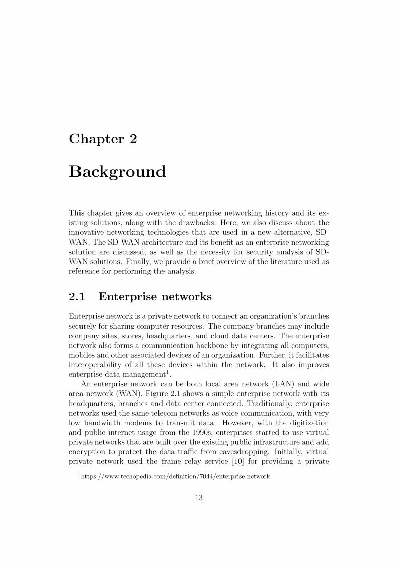
with customer edge routers is shown in Figure 2.2
Figure 2.2: MPLS Network [24]
The history of MPLS starts with Ipsilon networks, which proposed a flowmanagement protocol. This protocol works only over Asynchronous TransferMode (ATM). Later Cisco proposed tag switching, which is not restrictedonly to ATM. After some time, Cisco renamed it to label switching andgave it to IETF for open standardization. Then, various vendors startedto contribute and, thus it started to work with various technologies such asT1/E1, ATM, Frame Relay, and DSL. Since it works over various networkingprotocols, it is named as multiprotocol switching.
MPLS has many advantages compared to per-packet routing such as high-speed data transmission, scalability and flexibility to work over any underly-ing protocol. Because of these reasons, enterprise network widely use MPLSbased solutions. Service providers started to provide MPLS based solutionsto the enterprises. For example, Sonera in Finland provides a MPLS basedsolution called Datanet to its customers, and they are a market leader in thisbusiness in Finland.
2.3 Problems faced with MPLS
MPLS based solutions are widely accepted by most enterprises for their per-formance, yet there exists some disadvantages which create the need for newtechnology. The main disadvantages of MPLS are the costs and adaptation tonew technologies such as cloud. The cost of the MPLS based private WANis higher than the normal internet connectivity cost [11]. Apart from the
CHAPTER 2. BACKGROUND 16
cost, deploying MPLS network connection to a new branch location is timeconsuming. Currently, Sonera takes around 20 days to provide an MPLSconnection to a new customer site and it may even take longer depending onthe geographic location. The deployment requires manual work in configur-ing the customer premises router before sending it to the customer location.Further, a network professional is required at the branch location during thedeployment which adds to the operations costs.
Enterprises are moving towards the cloudification of their applications.They no longer spend time in setting up the infrastructure for their projects.They offload all their computation, storage and data to the public and privateclouds. As enterprises deploy their applications in easily available publicclouds such as Amazon AWS and Microsoft Azure, service providers faceproblems in providing MPLS connection to those public clouds from theenterprise sites. The cloud services can be taken into use within minutes,compared to the weeks of waiting for the MPLS connection. Moreover, somepublic cloud services may not support MPLS integration.
Further, MPLS is an old technology, which was developed in the 2000sand used for around 16 years. Over this time period, many new networkingtechnologies such as network virtualization and SDN have been developed.Therefore, it is not surprising that new alternatives have been developedto replace this traditional, difficult-to-deploy and expensive MPLS basedenterprise network with a more robust and cheaper solution.
2.4 Cutting-edge technologies
As mentioned in the previous section, there is a requirement for new enter-prise networking solutions that use all the latest networking technologies.With the evolution of networks over the years, many innovative technologieshave been developed which are discussed in this section.
Software-defined Networking
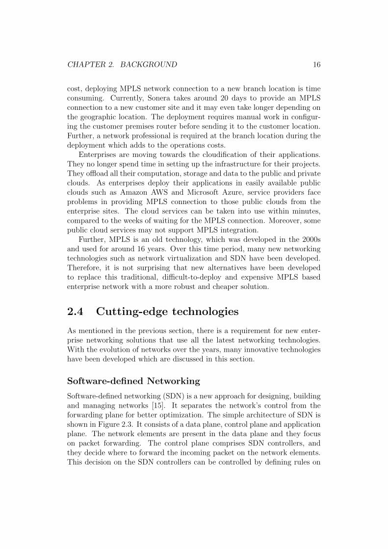
Software-defined networking (SDN) is a new approach for designing, buildingand managing networks [15]. It separates the network’s control from theforwarding plane for better optimization. The simple architecture of SDN isshown in Figure 2.3. It consists of a data plane, control plane and applicationplane. The network elements are present in the data plane and they focuson packet forwarding. The control plane comprises SDN controllers, andthey decide where to forward the incoming packet on the network elements.This decision on the SDN controllers can be controlled by defining rules on
CHAPTER 2. BACKGROUND 17
them. Thus, a controller is easily configurable and programmable. Theseflexibilities in SDN simplify networking.
Figure 2.3: Basic SDN Architecture
Network virtualisation
Network virtualization (NV) is the process of converting the network into asoftware entity known as virtual network, by decoupling the network fromthe underlying network hardware2. It virtualizes the network resources orpathways to achieve application or tenant isolation. In network virtualiza-tion, the L2-L7 network services are decoupled from the network hardwareand provided as a software to run the virtual network. NV solves many net-working challenges especially in data centers where the network needs to becreated on demand, without modifying the underlying infrastructure.
Network function virtualisation
Network function virtualization (NFV) is the concept of running a networkfunction in a virtual machine on the virtual server infrastructure [21]. The
2https://www.sdxcentral.com/sdn/network-virtualization/resources/whats-network-virtualization/
CHAPTER 2. BACKGROUND 18
network functions such as firewall, load balancer and NATs are tradition-ally run on a customized proprietary hardware and, through NFV, theseappliances could be replaced and run on the virtual machines. Usually, thetraditional hardware is expensive and results in high dependency on the ven-dor hardware. However, with the advancements in virtualization technologyand increase in the computing power of x86 microprocessors, network func-tions can be implemented as a virtual application. Thus, NFV reduces thecost and the vendor dependency for the network components.
Cloud computing
Cloud computing is the process of accessing, storing and computing data ondata centers over the internet, instead of our local machines. The datacenterscan be public, private or hybrid. Cloud computing provides high comput-ing power, high performance and scalability with low cost for the services.Due to the availability of high-speed networks and low-cost internet service,enterprises started to use cloud. It decreases the infrastructure set-up costsfor the enterprises as well reduces set-up time where they can focus on theirprojects instead of infrastructure setup. Cloud providers started to offer pay-as-you-go policies where customers are charged based on their usage. Apartfrom computing and storage, network solution can also be provided throughthe cloud by running virtualized network components in the cloud.
Overlay network and its encapsulation techniques
An overlay network is built on top of the existing physical network, connectedby the logical or virtual links. This virtual network allows the network re-source to be dynamically provisioned and, therefore, it is mainly used inthe cloud data centers where the network can be easily managed and provi-sioned based on the needs. The overlay network also offers programmabilityof network without changing the underlying network fabrics by adding theintelligent devices at the edges that can be programmed by the controller.These edge devices encapsulate the overlay network packets within the corenetwork packets, forming a virtual network among the edge devices. Thus,the encapsulation plays an important role in the overlay network. There aredifferent encapsulation techniques available such as VXLAN and GRE. Ofthese, VXLAN is widely used because of its scalability.
CHAPTER 2. BACKGROUND 19
VXLAN
Virtual Extensible LAN (VXLAN) is the encapsulation protocol used for run-ning an overlay network on an existing layer 3 infrastructure3. It is mainlyused in the WAN and cloud computing environments where isolation of ten-ants and apps is needed and the virtual networks may extend to many sitesover the public IP network. Each tenant in a cloud has its own logical networkand network ID, provided by VXLAN. VXLAN is an extension of traditionalVLAN, which is used only in the LAN environment because of its limited4096 network IDs. VXLAN has 16 million unique network IDs that allowsthis encapsulation technique to function over the WAN also.
2.5 SD-WAN solution
Using the above cutting-edge technologies, a new enterprise network solu-tion, SD-WAN has been developed. This section discusses the SD-WANarchitecture and its benefits.
Software defined wide area network (SD-WAN) solution is an internet-based, cloud-enabled networking service, offered to the enterprises. It vir-tualizes the networking service and eases the complexity of configuring andmanaging the enterprise network. It is based on the SDN overlay modelwhere the user traffic is encapsulated and then forwarded over the existingnetwork fabrics. The overlay model does not require any change in the ex-isting network fabric; rather it adds the intelligence to the edge device whichencapsulates the traffic4. The edge devices form a logically separate networkon top of the existing infrastructure. The logical network can be formed overany IP network irrespective of the underlying access technologies.
The controller in the control plane controls the edge devices. It acts asa data plane of the network where the traffic is processed as directed by thecontroller. Figure 2.4 shows the overlay network with edge devices forminga virtual network on top of the physical network. There exists a similarsoftware-defined overlay network in the cloud data centers where the networkis virtualized within the datacenter. We extend the same technology for theenterprise WANs across different geographic locations [17]. The edge devicesare provided as a customer premises equipment to all the branches and data-centers of the enterprise. A centralized controller controls these CPEs, andthe CPEs form a logically separate network using an encapsulation methodsuch as VXLAN or GRE. In addition, encrypting the encapsulated traffic
3http://whatis.techtarget.com/definition/VXLAN4https://www.sdxcentral.com/sdn/resources/what-is-overlay-networking/
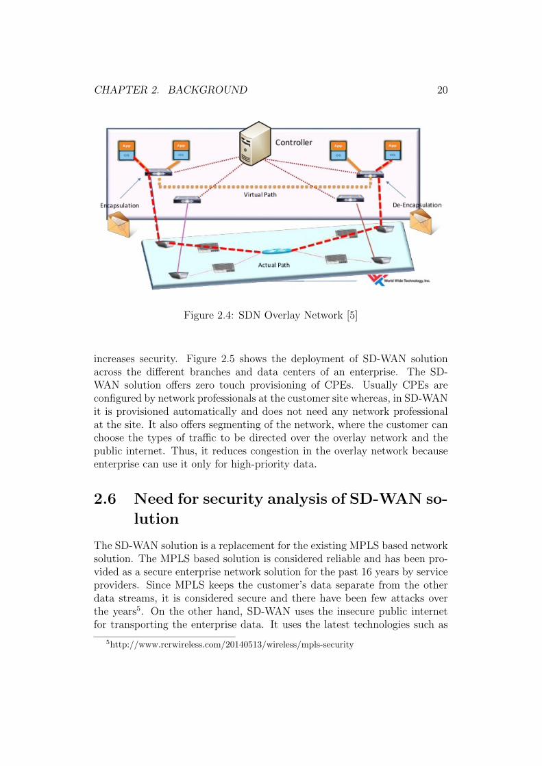
CHAPTER 2. BACKGROUND 20
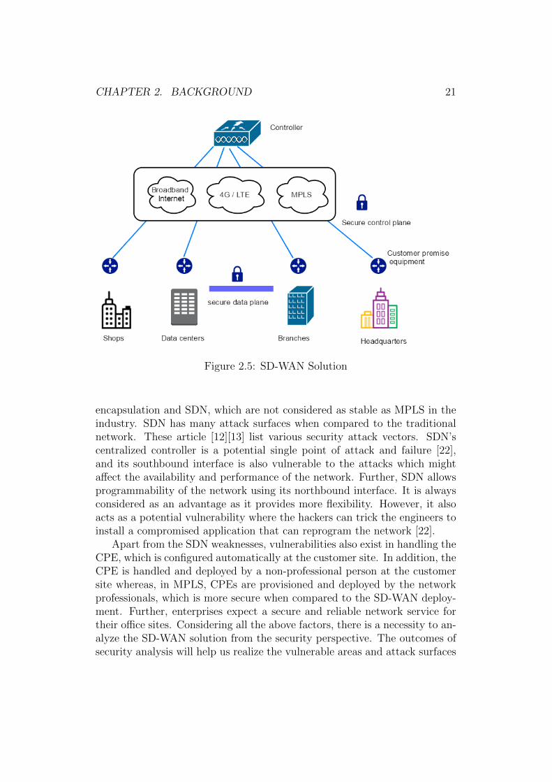
Figure 2.4: SDN Overlay Network [5]
increases security. Figure 2.5 shows the deployment of SD-WAN solutionacross the different branches and data centers of an enterprise. The SD-WAN solution offers zero touch provisioning of CPEs. Usually CPEs areconfigured by network professionals at the customer site whereas, in SD-WANit is provisioned automatically and does not need any network professionalat the site. It also offers segmenting of the network, where the customer canchoose the types of traffic to be directed over the overlay network and thepublic internet. Thus, it reduces congestion in the overlay network becauseenterprise can use it only for high-priority data.
2.6 Need for security analysis of SD-WAN so-
lution
The SD-WAN solution is a replacement for the existing MPLS based networksolution. The MPLS based solution is considered reliable and has been pro-vided as a secure enterprise network solution for the past 16 years by serviceproviders. Since MPLS keeps the customer’s data separate from the otherdata streams, it is considered secure and there have been few attacks overthe years5. On the other hand, SD-WAN uses the insecure public internetfor transporting the enterprise data. It uses the latest technologies such as
5http://www.rcrwireless.com/20140513/wireless/mpls-security
CHAPTER 2. BACKGROUND 21
Figure 2.5: SD-WAN Solution
encapsulation and SDN, which are not considered as stable as MPLS in theindustry. SDN has many attack surfaces when compared to the traditionalnetwork. These article [12][13] list various security attack vectors. SDN’scentralized controller is a potential single point of attack and failure [22],and its southbound interface is also vulnerable to the attacks which mightaffect the availability and performance of the network. Further, SDN allowsprogrammability of the network using its northbound interface. It is alwaysconsidered as an advantage as it provides more flexibility. However, it alsoacts as a potential vulnerability where the hackers can trick the engineers toinstall a compromised application that can reprogram the network [22].
Apart from the SDN weaknesses, vulnerabilities also exist in handling theCPE, which is configured automatically at the customer site. In addition, theCPE is handled and deployed by a non-professional person at the customersite whereas, in MPLS, CPEs are provisioned and deployed by the networkprofessionals, which is more secure when compared to the SD-WAN deploy-ment. Further, enterprises expect a secure and reliable network service fortheir office sites. Considering all the above factors, there is a necessity to an-alyze the SD-WAN solution from the security perspective. The outcomes ofsecurity analysis will help us realize the vulnerable areas and attack surfaces
CHAPTER 2. BACKGROUND 22
of SD-WAN, and these lessons can be used to propose countermeasures formitigating the attacks in the future.
2.7 Related literature
In the previous sections, we discussed about SD-WAN solution and the needfor security analysis for such solution. This section discusses the systematicanalysis procedure used while performing security analysis of SD-WAN. Werefer to the related literature works that performed similar security analysis.
ONUG SD-WAN working group has released a white paper [27] whichprovides a set of tactical and strategic requirements for an SD-WAN solution,including the security requirements. The important security requirements,to be considered are listed below.
1. Check the type of encryptions and the encryption algorithms, keylength and frequency of key rotation.
2. Check how the security threats such as spoofing, session hijacking andman-in-the-middle attack are handled.
3. Check the PKI (public key infrastructure) implementation and the CA(certification authority) associated with it. Check the process of keygeneration, distribution and revocation of invalid keys.
4. Check the controller’s security and access control for accessing its north-bound API.
5. Check how the AAA (authentication, authorization and accounting) ishandled in SD-WAN.
The above requirements are considered during our analysis and we ver-ified whether the given SD-WAN product satisfies them. Many researchpapers [33] [18] [32] [31] focus on the SDN’s controller security and lists thekey security issues to be considered while analyzing a controller. Some ofthe key security issues are unauthorized access, data leakage and denial ofservice, which have been considered during our analysis on SD-WAN’s con-troller. Then, we focused on the controller’s southbound interface that is theOpenFlow protocol in our case. We used [16] [2] [34] as references.
After analyzing the SDN components, we focused on the security of theCPE, which is usually a Linux box. We analyzed the attack surfaces of theCPE as guided in this research paper [19]. This paper analyses and mea-sures the given system’s attack surfaces in terms of three kinds of resources:
CHAPTER 2. BACKGROUND 23
methods, channels and data. Then, we concentrated on the PKI implemen-tation and the associated certification authority. The hierarchy of CAs andthe process of key generation and distribution are examined as in [8]. Gen-erally, misuse of keys and certificates leads to the man-in-the-middle attack[3][4], and we tested the possibilities of such attacks in SD-WAN. Finally, wefocused on verifying the access control implemented in the SD-WAN compo-nents. Usually, insufficient access control results in attacker acquiring highpriority information [30] and, therefore, role based access control has sug-gested for SD-WAN [39]. As the wider context for our work, we refer to theliterature on threat analysis [36][6] and penetration testing [37][9][1].
Chapter 3
Case study:Nuage VNS solution
In the previous chapter, we discussed the significance of SD-WAN for theenterprise networks and the need for security analysis for such solutions. Inthis chapter, we will do a case study of Nuage VNS, which is one of theSD-WAN solution available in the market. Our case study involves learningthe architecture of Nuage VNS and then analyzing them from the securityperspective. As a result, we found some vulnerabilities and performed someattacks, which are explained in the following chapter. We used Nuage VNSversion 3.2 release 6 for our analysis.
We divide this chapter into two sections where the first section explainsthe Nuage VNS architecture and its operation, and the second section de-scribes the outcomes of our analysis on the security features of Nuage VNS.
3.1 Nuage VNS architecture
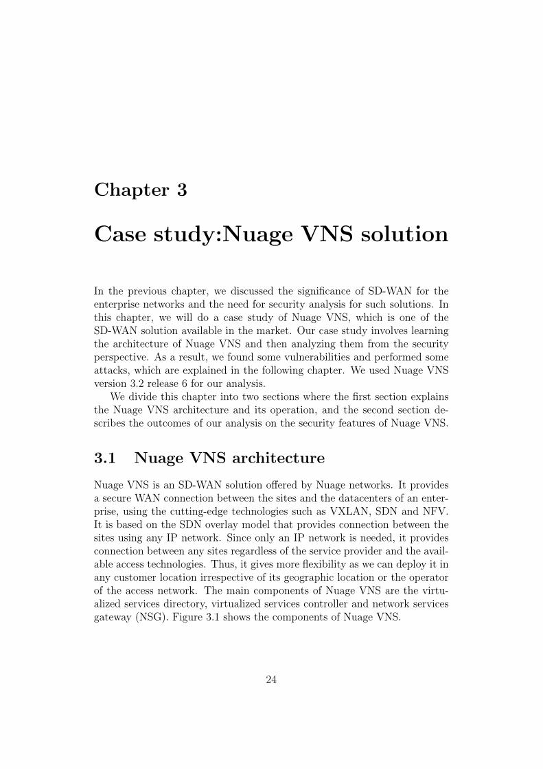
Nuage VNS is an SD-WAN solution offered by Nuage networks. It providesa secure WAN connection between the sites and the datacenters of an enter-prise, using the cutting-edge technologies such as VXLAN, SDN and NFV.It is based on the SDN overlay model that provides connection between thesites using any IP network. Since only an IP network is needed, it providesconnection between any sites regardless of the service provider and the avail-able access technologies. Thus, it gives more flexibility as we can deploy it inany customer location irrespective of its geographic location or the operatorof the access network. The main components of Nuage VNS are the virtu-alized services directory, virtualized services controller and network servicesgateway (NSG). Figure 3.1 shows the components of Nuage VNS.
24
CHAPTER 3. CASE STUDY:NUAGE VNS SOLUTION 25
Figure 3.1: Nuage VNS Architecture [25]
Virtualized services directory
Virtualized services directory (VSD) is the centralized policy engine thatmanages all the components of Nuage VNS solution. It defines rules andpolicies to all the NSGs located at the different enterprise sites. It is aprogrammable and analytics engine where the network policies can be eas-ily managed. It allows adding and moving new NSGs to the network viaa graphical user interface. Apart from the GUI, there is an API throughwhich network admin or user can manage the network services. VSDs canbe deployed as a single machine or in a cluster depending on the workloadand scaling needs.
The VSD also acts as a statistics server where the network traffic statisticsacross the sites are collected. These statistics are aggregated over hours, daysand months and stored in a Hadoop analytics cluster to facilitate data miningand performance reporting [26]. Further, VSD manages the security policiesfor all the NSGs. It also has an network function store from where usercan select the network functions needed for their service. Network functionsinclude services such as firewall, DNS and DHCP.
Virtualized services controller
The Nuage virtualized services controller (VSC) is the SDN controller ofthe Nuage VNS product. It acts as a robust control plane for the networkservices and maintains a complete view of network topologies and services.It has a northbound and southbound interface. The northbound interfacecan be accessed by VSD through the XMPP protocol. Apart from VSD, noother component can access the northbound interface of VSC. The south-
CHAPTER 3. CASE STUDY:NUAGE VNS SOLUTION 26
bound interface uses OpenFlow protocol to access the NSGs that act as adata-forwarding plane. VSC uses customized OpenFlow messages for pro-gramming the Open vSwitch residing in NSGs.
To provide redundancy and scalability, multiple VSC instances can beinstantiated within or across the network. The multiple VSC instances com-municate through the Multiprotocol Border Gateway Protocol (MP-BGP).MP-BGP is an extension to the Border Gateway Protocol (BGP) that enablesBGP to carry routing information for multiple network layers and addressfamilies [14]. It is a secure and highly scalable network technology to increasethe number of VSC instances according to the business requirements.
Network services gateway
Network services gateway (NSG) constitutes the data-forwarding plane forthe customer’s network. It acts as a customer premises equipment (CPE)which is placed in the different customer sites such as headquarters, branchesand private data centers. NSG is available as both physical hardware and vir-tual software. Physical hardware is placed in the branches and headquarterswhereas virtual NSG software is installed in the public and private clouds.NSG has an Open vSwitch that contacts the VSC through the OpenFlow pro-tocol. VSC applies the network policies, defined by VSD, to NSGs throughOpenFlow messages.
The NSG is deployed at the customer sites using an automated pro-cess called bootstrapping. Once bootstrapped, it creates an overlay virtualnetwork with the other NSGs of the enterprise. Then it encapsulates andde-encapsulates user traffic, enforcing Layer 2 to Layer 4 network policiesas defined by the VSD [26]. Further, encryption is also performed by NSGthrough IPsec. Service chaining can be instantiated at NSG by defining aservice policy in VSD. Service chaining includes services such as firewall,DHCP and DNS.
Other components
The other important components of Nuage VNS are key server, certificationauthority, notification application and proxy. The key server resides in theVSD and it generates the cryptographic keys and seeds needed for the NSGto encrypt user traffic. The configurations of the key server are managedby the admin through VSD. Certification authority (CA) is a public keyinfrastructure that issues certificates to the different components of the NuageVNS. These certificates are used for authorization and authentication of the
CHAPTER 3. CASE STUDY:NUAGE VNS SOLUTION 27
components during their communication. Further, it also verifies the digitalcertificates coming from the NSGs during the bootstrapping process.
Proxy, a separate entity, acts as an intermediary between the NSG andVSD for bootstrap requests. It intercepts all HTTPS requests between theNSG and VSD. It also serves as a certificate-based proxy offering multipleHTTPS endpoints. The notification application sends the activation mail tothe installer through the SMTP server. It also takes care of sending activationcode as an SMS to the installer during bootstrapping process. Usually, thenotification application is installed in the same machine as the proxy.
3.1.1 Nuage VNS operation
VSD and VSC are deployed within the service provider’s private trustednetwork. These software components can be installed in the virtual Linuxmachines running in the cloud such as OpenStack or VMware. NSG is a cus-tomer premises equipment (CPE), which is placed in the customer’s branchlocation. NSG, located in the customer site, communicates to VSD and VSCthrough the public internet. Apart from the physical NSG, we also have avirtual NSG, which is placed in the datacenter or private cloud of the enter-prise. These physical and virtual NSGs ensure secure communication amongthe branches and data centers of an enterprise. Figure 3.2 shows the NuageVNS based wide area network with NSGs deployed in the various branchesand data centers and private clouds of an enterprise.
On ordering, physical NSG boxes are delivered to the customer sites bythe service provider. The delivered NSG boxes are then deployed at the cus-tomer sites by an automated process called as bootstrapping. Whenever NSGis connected to the network at the customer site, the bootstrapping process isinitiated. It allows NSG to connect and authenticate itself to VSD by a two-factor authentication method. After successful authentication, NSG connectsto VSC and brings up a new customer site in the enterprise network. Alldevices behind the NSG are now connected to the enterprise network. Sincethe bootstrapping process is simple and automated, it does not require anynetwork specialist to be present at the customer site. Any non-professionalin the customer site can perform the bootstrapping. After the bootstrap-ping, NSG establishes a VXLAN overlay network connection with the NSGsof the other branch sites belonging to the same enterprise. It encapsulatesall its user traffic, enforcing Layer 2 to Layer4 network policies as defined bythe VSD. To ensure secure enterprise communication, it also encrypts theuser traffic before forwarding to other NSGs. As mentioned in Section 3.1,NSG forwards the traffic based on the network policies enforced by VSD.VSD can enforce policies such as traffic offloading where the NSG forwards
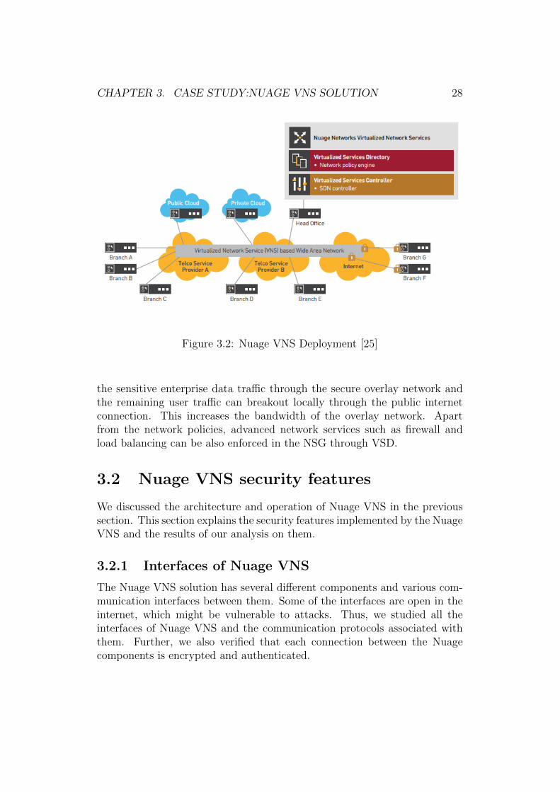
CHAPTER 3. CASE STUDY:NUAGE VNS SOLUTION 28
Figure 3.2: Nuage VNS Deployment [25]
the sensitive enterprise data traffic through the secure overlay network andthe remaining user traffic can breakout locally through the public internetconnection. This increases the bandwidth of the overlay network. Apartfrom the network policies, advanced network services such as firewall andload balancing can be also enforced in the NSG through VSD.
3.2 Nuage VNS security features
We discussed the architecture and operation of Nuage VNS in the previoussection. This section explains the security features implemented by the NuageVNS and the results of our analysis on them.
3.2.1 Interfaces of Nuage VNS
The Nuage VNS solution has several different components and various com-munication interfaces between them. Some of the interfaces are open in theinternet, which might be vulnerable to attacks. Thus, we studied all theinterfaces of Nuage VNS and the communication protocols associated withthem. Further, we also verified that each connection between the Nuagecomponents is encrypted and authenticated.
CHAPTER 3. CASE STUDY:NUAGE VNS SOLUTION 29
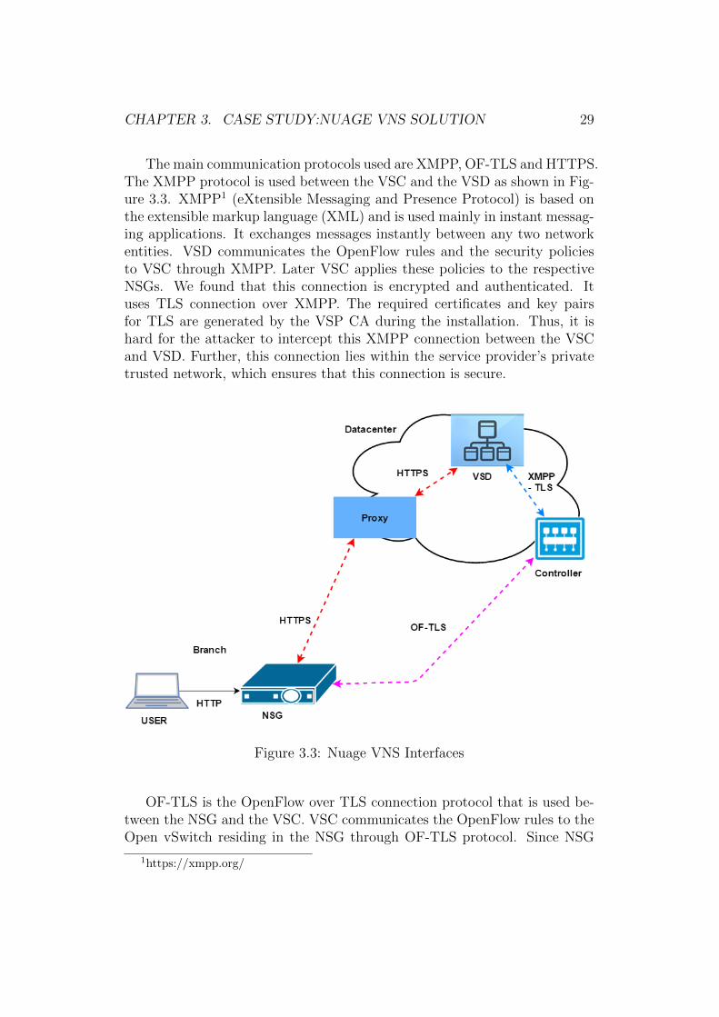
The main communication protocols used are XMPP, OF-TLS and HTTPS.The XMPP protocol is used between the VSC and the VSD as shown in Fig-ure 3.3. XMPP1 (eXtensible Messaging and Presence Protocol) is based onthe extensible markup language (XML) and is used mainly in instant messag-ing applications. It exchanges messages instantly between any two networkentities. VSD communicates the OpenFlow rules and the security policiesto VSC through XMPP. Later VSC applies these policies to the respectiveNSGs. We found that this connection is encrypted and authenticated. Ituses TLS connection over XMPP. The required certificates and key pairsfor TLS are generated by the VSP CA during the installation. Thus, it ishard for the attacker to intercept this XMPP connection between the VSCand VSD. Further, this connection lies within the service provider’s privatetrusted network, which ensures that this connection is secure.
Figure 3.3: Nuage VNS Interfaces
OF-TLS is the OpenFlow over TLS connection protocol that is used be-tween the NSG and the VSC. VSC communicates the OpenFlow rules to theOpen vSwitch residing in the NSG through OF-TLS protocol. Since NSG
1https://xmpp.org/
CHAPTER 3. CASE STUDY:NUAGE VNS SOLUTION 30
communicates with VSC on the customer site, this connection is establishedthrough the insecure public internet. However, this interface is authenticatedand data sent over this connection are always encrypted. The encryption usesthe VSP CA’s certificates and key pairs present in the NSG and the VSC.Open vSwitch, which resides in the NSG, is customized and uses proprietaryOpenFlow messages. Thus it hard for the attackers to read this connection.
HTTPS is a standard HTTP over TLS connection, which is used be-tween the NSG, proxy and the VSD. This connection is initiated mainlyduring the bootstrapping process where NSG queries VSD via the proxy forcertificates and configuration. NSG authentication is also performed throughthis HTTPS connection. Once authenticated, VSD sends the VSP CA cer-tificates, key pairs and configuration information through this connection.We have two HTTPS connection between the proxy and NSG, one over port12443 and other over 11443. Each uses its own set of certificates and keypairs while establishing a HTTPS connection.
Thus, all the interfaces between the VNS components are encrypted, au-thenticated and therefore appear to be well protected from the outsiders.
3.2.2 NSG and the bootstrapping process
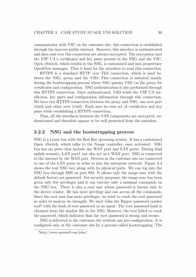
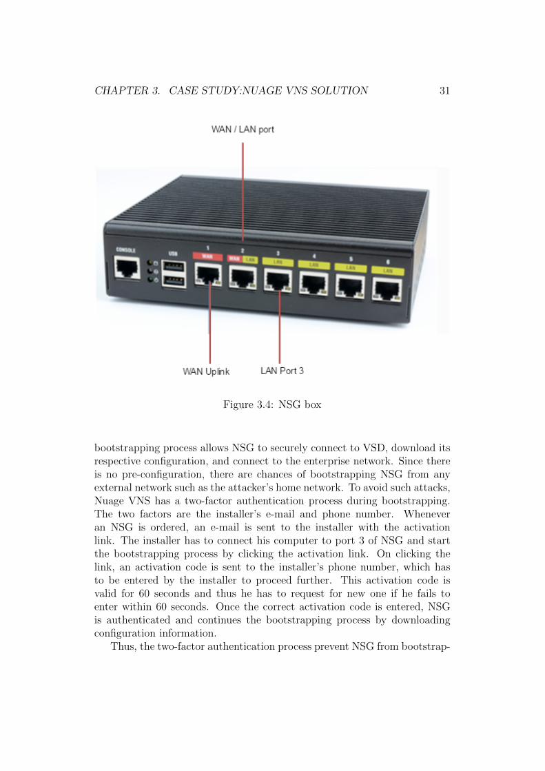
NSG is a Linux box with the Red Hat operating system. It has a customizedOpen vSwitch, which talks to the Nuage controller, once activated. NSGbox has six ports that include one WAN port and LAN ports. During dualuplink scenario, LAN port1 can also act as a WAN port. NSG is connectedto the internet by the WAN port. Devices at the customer site are connectedto one of the LAN ports in order to join the enterprise network. Figure 3.4shows the real NSG box along with its physical ports. We can log into theNSG box through SSH on port 893. It allows only the nuage user with thedefault factory-set password. For security purposes, the nuage user has beengiven only few privileges and it can execute only a minimal commands onthe NSG box. There is also a root user whose password is known only tothe device vendor. He has more privilege and can access all the commands.Since the root user has more privileges, we tried to crack the root passwordin order to analyze its strength. We used John the Ripper password crackertool2 with the hash of root password as an input. The root password hash isobtained from the shadow file in the NSG. However, the tool failed to crackthe password, which indicates that the root password is strong and secure.
NSG is delivered to the customer site without any pre-configuration. It isconfigured only at the customer site by a process called bootstrapping. The
2http://www.openwall.com/john/
CHAPTER 3. CASE STUDY:NUAGE VNS SOLUTION 31
Figure 3.4: NSG box
bootstrapping process allows NSG to securely connect to VSD, download itsrespective configuration, and connect to the enterprise network. Since thereis no pre-configuration, there are chances of bootstrapping NSG from anyexternal network such as the attacker’s home network. To avoid such attacks,Nuage VNS has a two-factor authentication process during bootstrapping.The two factors are the installer’s e-mail and phone number. Wheneveran NSG is ordered, an e-mail is sent to the installer with the activationlink. The installer has to connect his computer to port 3 of NSG and startthe bootstrapping process by clicking the activation link. On clicking thelink, an activation code is sent to the installer’s phone number, which hasto be entered by the installer to proceed further. This activation code isvalid for 60 seconds and thus he has to request for new one if he fails toenter within 60 seconds. Once the correct activation code is entered, NSGis authenticated and continues the bootstrapping process by downloadingconfiguration information.
Thus, the two-factor authentication process prevent NSG from bootstrap-
CHAPTER 3. CASE STUDY:NUAGE VNS SOLUTION 32
ping in any external network and getting nevertheless connected to the en-terprise network.
3.2.3 Control plane security: VSC security
This section analyses the security of VSC that acts as a control plane inthe Nuage VNS services. Being a controller, VSC manages the whole data-forwarding plane and plays an important role in managing the network ser-vices across the branch sites. In the world of SDN, the security of controlleris a major concern as it is a potential single point of attack and failure [22].There are several attacks possible on the controller [7]. Attackers can alsoperform a denial of service attack [38] on controller in order to disrupt thenetwork service. Further, the northbound interface of the controller will bethe attacker’s main target as it allows to degrade and modify the networkusing programmable APIs [12]. Considering the importance, we investigatedthe security of VSC in detail, including all its accessible interfaces.
VSC is provided as a virtual machine application, which can be instanti-ated on the cloud such as OpenStack and VMware. It is built over the AlcatelLucent’s service router operating system. It is a proven, robust and secureoperating system as many of the routers in the world are running it. Theoperating system is hardened in such a way that the user can access onlylimited commands. VSCs management interface has an industry-standardCLI, which looks similar to SNMP management. Thus, it avoids the criti-cal command execution that may affect the data plane. Further, the VSCnorthbound interface can be accessed only by the VSD through XMPP-TLS.Apart from VSD, no other third-party application is allowed to access thenorthbound API, which makes the system robust. The southbound interfaceuses OpenFlow over TLS. TLS is made mandatory in order to avoid eaves-dropping and spoofed OpenFlow messages. VSC also allows redundancy incase of failure of anyone of them.
3.2.4 IPsec key rotation method
NSG performs IPsec encryption of user traffic that traverses over the WANnetworks between the branch sites or between the branch and headquarters.We analyzed this IPsec encryption to understand the steps and encryptionmethods used. This section explains those methods and the security consid-ered in them.
IPsec encryption uses a symmetric key for encrypting and decryptingthe user traffic. All NSGs use the same traffic encryption key (TEK) ata time, and these keys are periodically changed by the key server in VSD
CHAPTER 3. CASE STUDY:NUAGE VNS SOLUTION 33
using a key rotation method. Since the TEKs are changed periodically, timeis synchronized among all NSGs using an NTP server. VSC acts as theNTP server that periodically updates time to all NSGs. This prevents atime mismatch in NSGs which could lead to a failure of the key rotationmethod. Further, VSC updates time using the OF-TLS connection, which isan encrypted and authenticated connection. This prevents NTP spoofing onNSGs.
To make the key rotation method secure, the TEKs are not directly dis-tributed among the NSGs. Instead, they distribute the following crypto-graphic materials, seed encryption key (SEK) and seed among the NSGs.SEK is internally generated by the Key Server and it is encrypted using thepublic key of the NSG, which is generated as a part of bootstrapping pro-cess. These encrypted SEKs are stored in the key server for distribution tothe NSGs later. The seed is the keying material for generating TEKs in theNSG. The seed material is encrypted using SEK and signed by the key server.It is also stored in key server for later distribution.
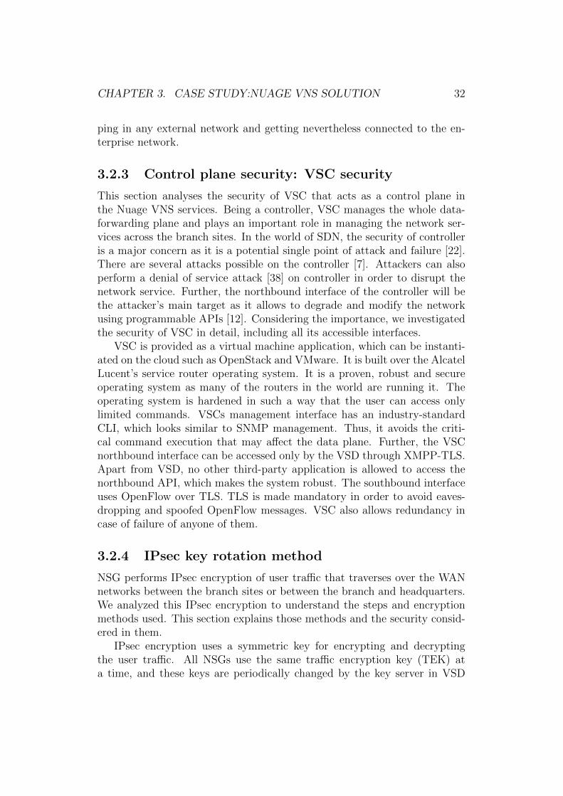
Figure 3.5: Key transport path
The encrypted SEKs and seed are distributed to NSGs in the followingsteps.
1. The encrypted SEK is first distributed to the NSGs by the key server.
CHAPTER 3. CASE STUDY:NUAGE VNS SOLUTION 34
NSG decrypts SEK using its private key and stores it.
2. Now, the encrypted seed is distributed by the key server to NSGs. NSGdecrypts the seed using the SEK obtained in the first step.
3. NSG generates TEK using the seed material obtained in the secondstep. NSG uses a proprietary algorithm to generate TEK from theseed.
4. TEK remains the same across all NSGs at a particular time. User trafficis encrypted using TEK and decrypted by other NSGs using their copyof the TEK.
The SEKs and seed are distributed in the following path as shown in Fig-ure 3.5. It is transported from VSD to VSC over XMPP-TLS and from VSCto NSG over OF-TLS. Both these connections are encrypted and authenti-cated, which prevents outsiders to access these keys. Further, encryption andsigning of the seed material uses updated protocols such as HMAC SHA-1for authentication, AES256 CBC for encryption, and SHA-256 with RSA forsigning. It appears that the IPsec encryption method is secure enough. Incase if any NSG is compromised, then the admin can revoke all keys in theNSGs and generate and distribute new SEKs, seeds and TEKs.
Thus, as far as we can see the key rotation method provides secure IPsecencryption of user traffic among the NSGs.
Chapter 4
Vulnerabilities and attack scenar-ios
We performed security analysis of each component of the Nuage VNS plat-form and the interfaces among them. The focus of our analysis was primarilyon the Network Service Gateway (NSG) since it is available on the customerpremises and easily accessible to an attacker when compared to the othercomponents. Further, a non-professional at the branch office handles NSG.He performs the NSGs activation that involves the two-factor authenticatedbootstrapping process as mentioned in Section 3.2.2. Despite the two-factorauthentication, we suspected potential vulnerabilities and investigated on itfurther. Thus, our analysis concentrated on the NSG and its bootstrappingprocess. On detailed enquiry, we found some vulnerabilities in the NSG. Fur-ther, we also found some attacks possible on the NSG during bootstrappingprocess. These vulnerabilities and attacks are explained in this chapter.
Throughout this chapter, we specify three roles: vendor, service providerand customer. The vendor refers to the technology provider, which is NuageNetworks in our case. The service provider refers to operators such as Sonera.Customers are the enterprises who buy the technology and WAN service fromthe service provider and deploy it at their sites.
4.1 Analysis of NSG attack surfaces
In this section, we look into the attack surfaces of the NSG. We analysedthe different possible ways to access this Linux box, NSG. As mentioned inSection 3.2.2, a user can connect to NSG through six physical ports. Apartfrom these physical ports, we analysed other possible ways to access the NSG
35
CHAPTER 4. VULNERABILITIES AND ATTACK SCENARIOS 36
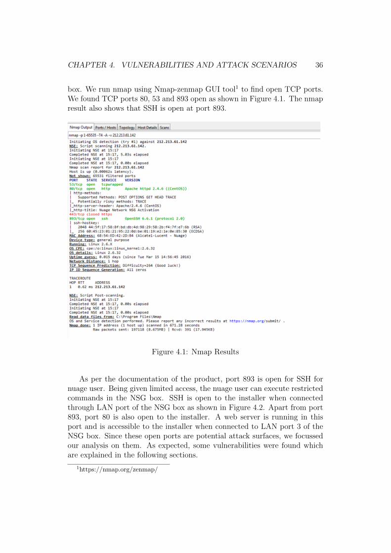
box. We run nmap using Nmap-zenmap GUI tool1 to find open TCP ports.We found TCP ports 80, 53 and 893 open as shown in Figure 4.1. The nmapresult also shows that SSH is open at port 893.
Figure 4.1: Nmap Results
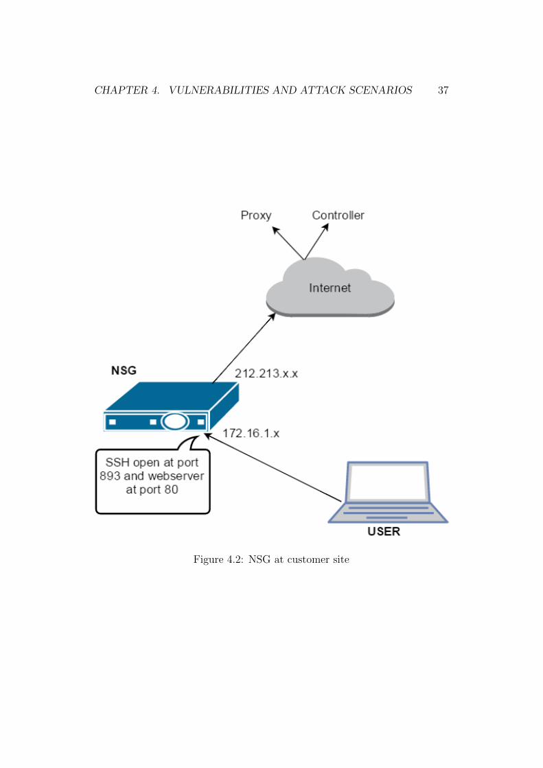
As per the documentation of the product, port 893 is open for SSH fornuage user. Being given limited access, the nuage user can execute restrictedcommands in the NSG box. SSH is open to the installer when connectedthrough LAN port of the NSG box as shown in Figure 4.2. Apart from port893, port 80 is also open to the installer. A web server is running in thisport and is accessible to the installer when connected to LAN port 3 of theNSG box. Since these open ports are potential attack surfaces, we focussedour analysis on them. As expected, some vulnerabilities were found whichare explained in the following sections.
1https://nmap.org/zenmap/
CHAPTER 4. VULNERABILITIES AND ATTACK SCENARIOS 37
Figure 4.2: NSG at customer site
CHAPTER 4. VULNERABILITIES AND ATTACK SCENARIOS 38
4.2 Basic vulnerabilities
This chapter explains some of the simple vulnerabilities found in the NSGbox. We will explain the vulnerabilities in the increasing order of criticalitywith the simple ones are explained in the initial sections, followed by thecomplex ones in the following sections.
4.2.1 Vulnerability 1: open SSH port
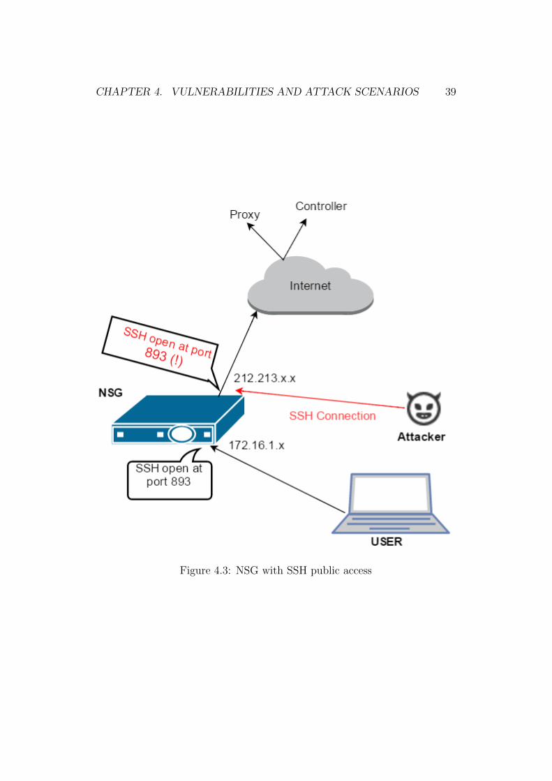
On investigation, we found that SSH port on the NSG is open to the interneton the WAN port with the default username and password. Usually, NSGboxes are shipped directly from the factory to the customer site with thedefault password. The customer has to change the default password on firstSSH login. However, most customers do not have any reason to connect withSSH and hence there is a high chance that NSG boxes would be deployedat the customer sites with the default password. Therefore, the attacker canlogin to those NSGs from any location on the internet. NSG also forces oneto change the default password on the first login. Therefore, the attacker willchange the default password before the innocent customer changes it. Figure4.3 shows the NSG with the open SSH port and the attacker accessing itfrom different location. Once logged in to the NSG, the attacker can accessit with the limited nuage user rights.
Attacker could exploit this SSH weakness and perform the attack below.We assume that attacker knows the default password and the range of IPaddresses where the NSGs are being deployed.
Attack steps
1. Attacker performs a slow scan of the service provider’s IP address spacefor SSH servers in port 893.
2. Attacker tries to log in to these nodes with the username nuage andthe default password.
3. If the login is successful, the attacker sets his own password.
4. Attacker can now access the NSG with the nuage user rights. Forexample, he can reconfigure the iptables firewall policy of the NSG.
Apart from the nuage user, root user can also login through port 893.Only the vendor knows the root password and the root can perform all op-erations in NSG. Therefore, the vendors has access to the NSG boxes at the
CHAPTER 4. VULNERABILITIES AND ATTACK SCENARIOS 39
Figure 4.3: NSG with SSH public access
CHAPTER 4. VULNERABILITIES AND ATTACK SCENARIOS 40
customer sites and can control the customer’s network without the help ofthe service provider.
4.2.2 Vulnerability 2: open HTTP port
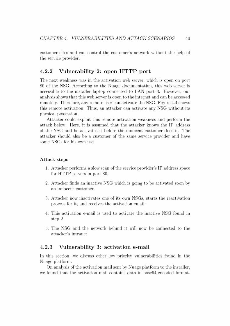
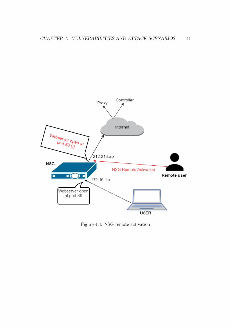
The next weakness was in the activation web server, which is open on port80 of the NSG. According to the Nuage documentation, this web server isaccessible to the installer laptop connected to LAN port 3. However, ouranalysis shows that this web server is open to the internet and can be accessedremotely. Therefore, any remote user can activate the NSG. Figure 4.4 showsthis remote activation. Thus, an attacker can activate any NSG without itsphysical possession.
Attacker could exploit this remote activation weakness and perform theattack below. Here, it is assumed that the attacker knows the IP addressof the NSG and he activates it before the innocent customer does it. Theattacker should also be a customer of the same service provider and havesome NSGs for his own use.
Attack steps
1. Attacker performs a slow scan of the service provider’s IP address spacefor HTTP servers in port 80.
2. Attacker finds an inactive NSG which is going to be activated soon byan innocent customer.
3. Attacker now inactivates one of its own NSGs, starts the reactivationprocess for it, and receives the activation email.
4. This activation e-mail is used to activate the inactive NSG found instep 2.
5. The NSG and the network behind it will now be connected to theattacker’s intranet.
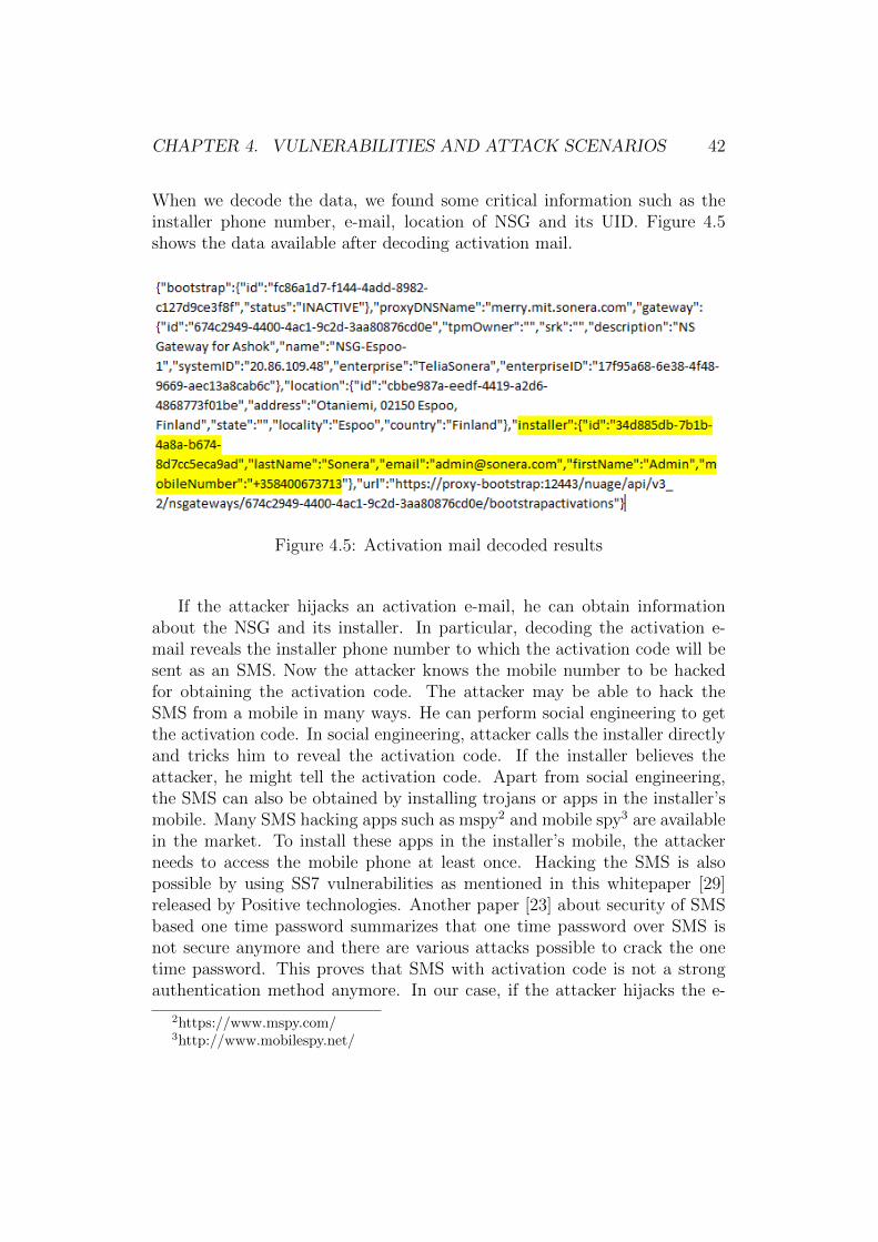
4.2.3 Vulnerability 3: activation e-mail
In this section, we discuss other low priority vulnerabilities found in theNuage platform.
On analysis of the activation mail sent by Nuage platform to the installer,we found that the activation mail contains data in base64-encoded format.
CHAPTER 4. VULNERABILITIES AND ATTACK SCENARIOS 41
Figure 4.4: NSG remote activation
CHAPTER 4. VULNERABILITIES AND ATTACK SCENARIOS 42
When we decode the data, we found some critical information such as theinstaller phone number, e-mail, location of NSG and its UID. Figure 4.5shows the data available after decoding activation mail.
Figure 4.5: Activation mail decoded results
If the attacker hijacks an activation e-mail, he can obtain informationabout the NSG and its installer. In particular, decoding the activation e-mail reveals the installer phone number to which the activation code will besent as an SMS. Now the attacker knows the mobile number to be hackedfor obtaining the activation code. The attacker may be able to hack theSMS from a mobile in many ways. He can perform social engineering to getthe activation code. In social engineering, attacker calls the installer directlyand tricks him to reveal the activation code. If the installer believes theattacker, he might tell the activation code. Apart from social engineering,the SMS can also be obtained by installing trojans or apps in the installer’smobile. Many SMS hacking apps such as mspy2 and mobile spy3 are availablein the market. To install these apps in the installer’s mobile, the attackerneeds to access the mobile phone at least once. Hacking the SMS is alsopossible by using SS7 vulnerabilities as mentioned in this whitepaper [29]released by Positive technologies. Another paper [23] about security of SMSbased one time password summarizes that one time password over SMS isnot secure anymore and there are various attacks possible to crack the onetime password. This proves that SMS with activation code is not a strongauthentication method anymore. In our case, if the attacker hijacks the e-
2https://www.mspy.com/3http://www.mobilespy.net/
CHAPTER 4. VULNERABILITIES AND ATTACK SCENARIOS 43
mail, he may be able break the second factor SMS by trying one of the abovemethods.
Further analysis shows that there is no time stamp in the activation mail,which allows activating an NSG with any old activation e-mail that has notyet been used. Thus, the attacker will be successful in his attacks if he hijacksany of the old activation e-mails, provided that the NSG profile associatedwith that activation mail has not been used or deleted in the Nuage platformyet.
We continued our analysis by modifying the values of the activation e-mail and found that the Nuage platform expects only the UID parameterwith the correct value. The remaining parameters can be fake values, andhence the attacker can compose his own e-mail by giving only the correct UIDand proxy address. Therefore, the e-mail, the first factor of the two-factorauthentication, relies on the UID value. Besides that, the attacker couldalso tamper the e-mail by modifying the proxy address and UID. This causea minor denial of service attack for a short interval as the NSG activationdepends on the UID value.
Apart from the above vulnerabilities, there are other social factors af-fecting the security of this system. Social factors refer to mistakes madeby human beings while handling the customers. One example could be thescenario in handling big customers. Usually, a big customer orders a largenumber of NSGs for the customer sites from the service provider. Whileordering, they would prefer not to enter the installer’s details for all the cus-tomer sites and mostly end up filling in only IT admin details. The IT adminreceives all the activation e-mails and codes, which would be forwarded tothe installers in the different customer sites. Forwarding the e-mails andactivation codes is not always a secure way, and attacker could use thesecircumstances in his favour. The service provider should avoid these kind ofbatch deliveries while handling big customers.
4.3 Attacks against the NSG bootstrapping
process
In the previous section, we discussed various vulnerabilities and attacks onthe NSG interfaces. This section discusses the vulnerabilities found in thebootstrapping process. This section is divided into two subsections wherethe first subsection describes the steps involved in the NSG’s bootstrappingprocess and the weaknesses associated with it, and the second subsectiondemonstrates the possible attacks on the NSG based on its bootstrapping
CHAPTER 4. VULNERABILITIES AND ATTACK SCENARIOS 44
weaknesses.
4.3.1 NSG bootstrapping process
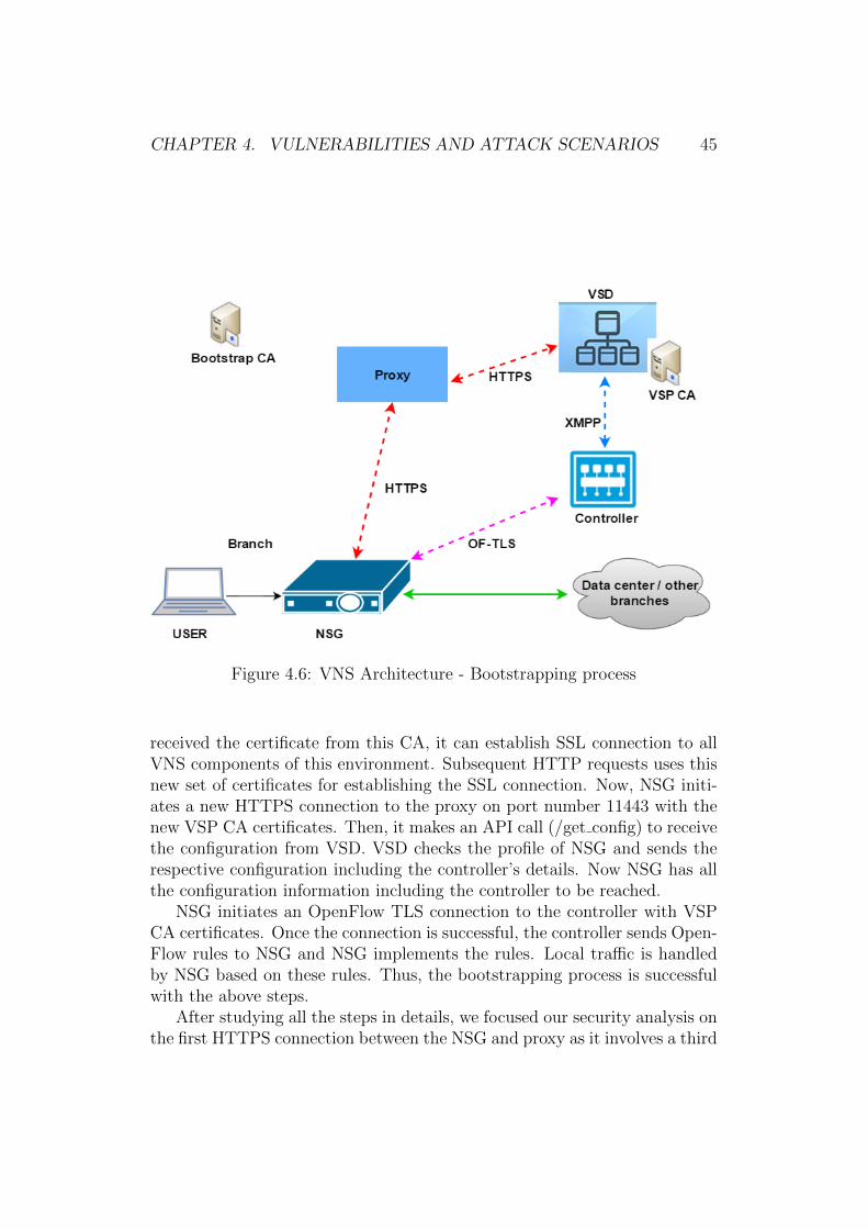
Bootstrapping is the initial part of the deployment where NSG securely con-nects to the controller from the customer site. The installer connected to theNSG at the customer site initiates this process. At the end of a successfulbootstrapping process, NSG will become active and the devices connectedto it are attached to the respective enterprise network. The main VNS com-ponents involved during the bootstrapping process are the proxy and VSD.When the installer is connected to port 3 of NSG and clicks the link in theactivation e-mail, NSG initiates an HTTPS connection to VSD through theproxy. The proxy lies between NSG and backend VSD, and acts as an inter-mediary for the requests coming from the NSG towards the backend VSD.Then, NSG authenticates itself with VSD and downloads all configuration in-formation including the controller details. Finally, it establishes a connectionwith the respective controller and connects to the enterprise network. TheNuage VNS architecture is shown in Figure 4.6, highlighting the componentsand interfaces involved during the bootstrapping process.
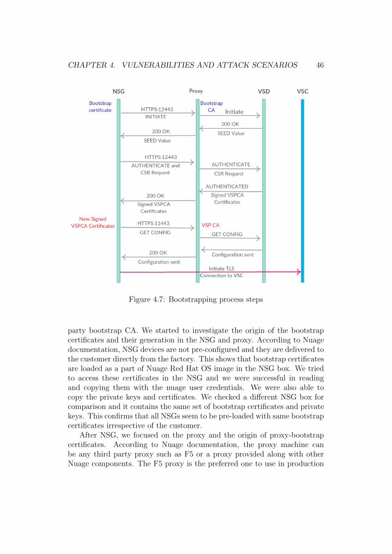
To analyse further, we studied each step of the bootstrapping processin detail. Figure 4.7 shows all the steps between the NSG and the Nuagecomponents during bootstrapping process. NSG initiates an HTTPS con-nection to proxy on port number 12443. It uses the nsg-bootstrap certificateon the NSG side and the proxy-bootstrap certificate in server side, whichis the proxy. The bootstrap certification authority, a third party CA, signsboth these certificates. We do not have information about the origin of thebootstrap CA. Port 12443 is used only for the initial two HTTPS connec-tions between the NSG and proxy. Initially, NSG makes an API call /initiatein the first request. VSD responds by generating a code and sending it asthe SMS to the installer’s mobile number. A notification agent connected toVSD performs this operation. This API call also returns a seed value to NSG.When the installer enters the code received via SMS, NSG initiates a secondAPI call (/authenticate) with the hash values of the seed and the code. Ad-ditionally, NSG also requests SSL certificates by sending certificate-signingrequest to VSD. The hash values of the code and the seed are used for au-thentication. If they are correct, VSD accepts NSG and generates certificatesfor the CSR. These certificates are generated by the VSP certification au-thority, which resides in VSD. The generated digital certificates are sent backto NSG. NSG is authenticated now and it contains digitally signed certifi-cates from VSP CA, which is the central certification authority for providingcertificates to all VNS components of this operator environment. Since NSG
CHAPTER 4. VULNERABILITIES AND ATTACK SCENARIOS 45
Figure 4.6: VNS Architecture - Bootstrapping process
received the certificate from this CA, it can establish SSL connection to allVNS components of this environment. Subsequent HTTP requests uses thisnew set of certificates for establishing the SSL connection. Now, NSG initi-ates a new HTTPS connection to the proxy on port number 11443 with thenew VSP CA certificates. Then, it makes an API call (/get config) to receivethe configuration from VSD. VSD checks the profile of NSG and sends therespective configuration including the controller’s details. Now NSG has allthe configuration information including the controller to be reached.
NSG initiates an OpenFlow TLS connection to the controller with VSPCA certificates. Once the connection is successful, the controller sends Open-Flow rules to NSG and NSG implements the rules. Local traffic is handledby NSG based on these rules. Thus, the bootstrapping process is successfulwith the above steps.
After studying all the steps in details, we focused our security analysis onthe first HTTPS connection between the NSG and proxy as it involves a third
CHAPTER 4. VULNERABILITIES AND ATTACK SCENARIOS 46
Figure 4.7: Bootstrapping process steps
party bootstrap CA. We started to investigate the origin of the bootstrapcertificates and their generation in the NSG and proxy. According to Nuagedocumentation, NSG devices are not pre-configured and they are delivered tothe customer directly from the factory. This shows that bootstrap certificatesare loaded as a part of Nuage Red Hat OS image in the NSG box. We triedto access these certificates in the NSG and we were successful in readingand copying them with the nuage user credentials. We were also able tocopy the private keys and certificates. We checked a different NSG box forcomparison and it contains the same set of bootstrap certificates and privatekeys. This confirms that all NSGs seem to be pre-loaded with same bootstrapcertificates irrespective of the customer.
After NSG, we focused on the proxy and the origin of proxy-bootstrapcertificates. According to Nuage documentation, the proxy machine canbe any third party proxy such as F5 or a proxy provided along with otherNuage components. The F5 proxy is the preferred one to use in production
CHAPTER 4. VULNERABILITIES AND ATTACK SCENARIOS 47
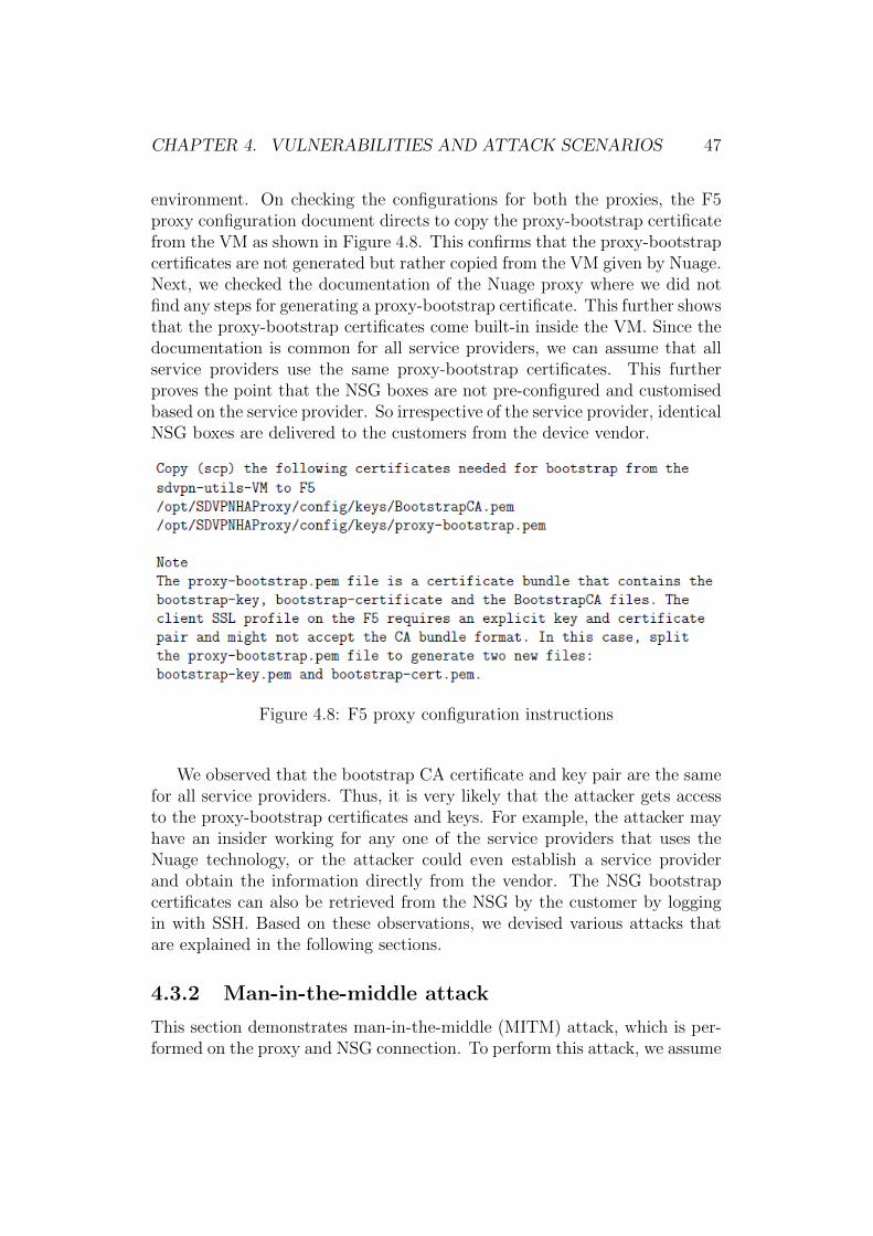
environment. On checking the configurations for both the proxies, the F5proxy configuration document directs to copy the proxy-bootstrap certificatefrom the VM as shown in Figure 4.8. This confirms that the proxy-bootstrapcertificates are not generated but rather copied from the VM given by Nuage.Next, we checked the documentation of the Nuage proxy where we did notfind any steps for generating a proxy-bootstrap certificate. This further showsthat the proxy-bootstrap certificates come built-in inside the VM. Since thedocumentation is common for all service providers, we can assume that allservice providers use the same proxy-bootstrap certificates. This furtherproves the point that the NSG boxes are not pre-configured and customisedbased on the service provider. So irrespective of the service provider, identicalNSG boxes are delivered to the customers from the device vendor.
Figure 4.8: F5 proxy configuration instructions
We observed that the bootstrap CA certificate and key pair are the samefor all service providers. Thus, it is very likely that the attacker gets accessto the proxy-bootstrap certificates and keys. For example, the attacker mayhave an insider working for any one of the service providers that uses theNuage technology, or the attacker could even establish a service providerand obtain the information directly from the vendor. The NSG bootstrapcertificates can also be retrieved from the NSG by the customer by loggingin with SSH. Based on these observations, we devised various attacks thatare explained in the following sections.
4.3.2 Man-in-the-middle attack
This section demonstrates man-in-the-middle (MITM) attack, which is per-formed on the proxy and NSG connection. To perform this attack, we assume
CHAPTER 4. VULNERABILITIES AND ATTACK SCENARIOS 48
that globally the same bootstrap keys are used and the attacker is capable ofgetting those keys. Based on these assumptions, two types of MITM attacksare possible. They are MITM on-path and MITM off-path attack.
MITM on-path
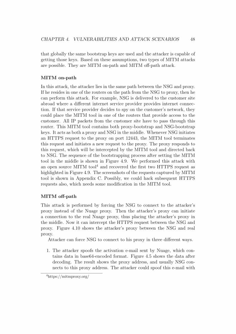
In this attack, the attacker lies in the same path between the NSG and proxy.If he resides in one of the routers on the path from the NSG to proxy, then hecan perform this attack. For example, NSG is delivered to the customer siteabroad where a different internet service provider provides internet connec-tion. If that service provider decides to spy on the customer’s network, theycould place the MITM tool in one of the routers that provide access to thecustomer. All IP packets from the customer site have to pass through thisrouter. This MITM tool contains both proxy-bootstrap and NSG-bootstrapkeys. It acts as both a proxy and NSG in the middle. Whenever NSG initiatesan HTTPS request to the proxy on port 12443, the MITM tool terminatesthis request and initiates a new request to the proxy. The proxy responds tothis request, which will be intercepted by the MITM tool and directed backto NSG. The sequence of the bootstrapping process after setting the MITMtool in the middle is shown in Figure 4.9. We performed this attack withan open source MITM tool4 and recovered the first two HTTPS request ashighlighted in Figure 4.9. The screenshots of the requests captured by MITMtool is shown in Appendix C. Possibly, we could hack subsequent HTTPSrequests also, which needs some modification in the MITM tool.
MITM off-path
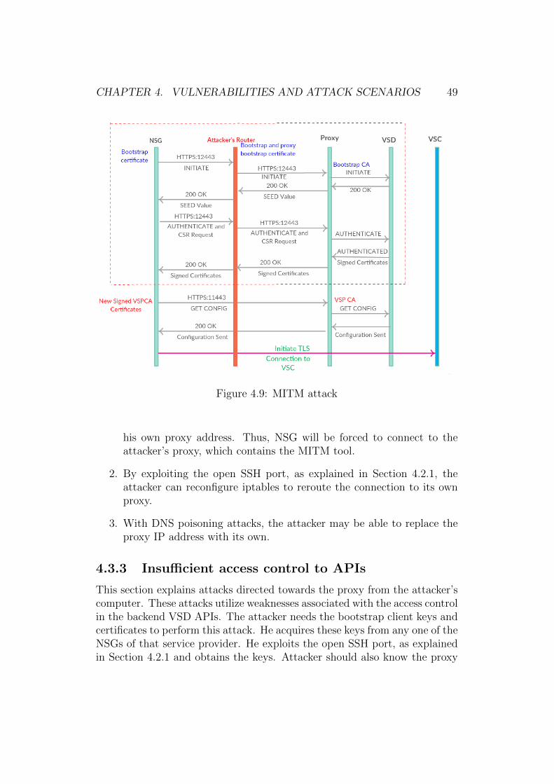
This attack is performed by forcing the NSG to connect to the attacker’sproxy instead of the Nuage proxy. Then the attacker’s proxy can initiatea connection to the real Nuage proxy, thus placing the attacker’s proxy inthe middle. Now it can intercept the HTTPS request between the NSG andproxy. Figure 4.10 shows the attacker’s proxy between the NSG and realproxy.
Attacker can force NSG to connect to his proxy in three different ways.
1. The attacker spoofs the activation e-mail sent by Nuage, which con-tains data in base64-encoded format. Figure 4.5 shows the data afterdecoding. The result shows the proxy address, and usually NSG con-nects to this proxy address. The attacker could spoof this e-mail with
4https://mitmproxy.org/
CHAPTER 4. VULNERABILITIES AND ATTACK SCENARIOS 49
Figure 4.9: MITM attack
his own proxy address. Thus, NSG will be forced to connect to theattacker’s proxy, which contains the MITM tool.
2. By exploiting the open SSH port, as explained in Section 4.2.1, theattacker can reconfigure iptables to reroute the connection to its ownproxy.
3. With DNS poisoning attacks, the attacker may be able to replace theproxy IP address with its own.
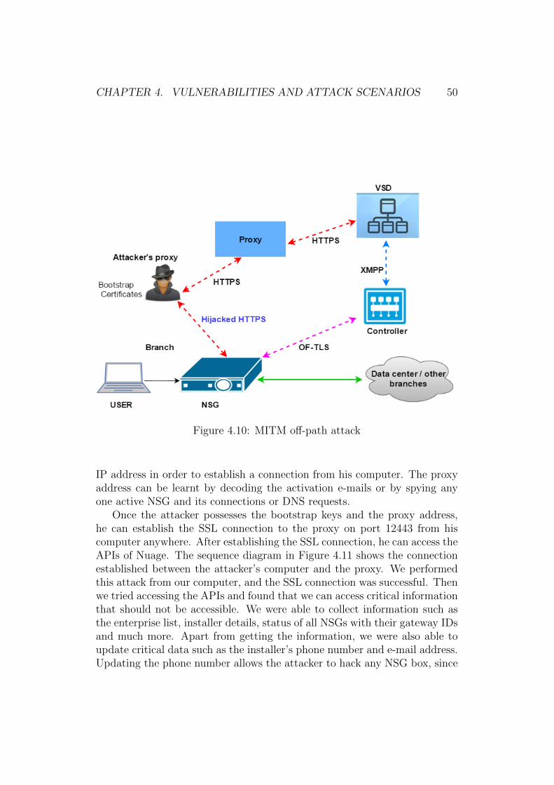
4.3.3 Insufficient access control to APIs
This section explains attacks directed towards the proxy from the attacker’scomputer. These attacks utilize weaknesses associated with the access controlin the backend VSD APIs. The attacker needs the bootstrap client keys andcertificates to perform this attack. He acquires these keys from any one of theNSGs of that service provider. He exploits the open SSH port, as explainedin Section 4.2.1 and obtains the keys. Attacker should also know the proxy
CHAPTER 4. VULNERABILITIES AND ATTACK SCENARIOS 50
Figure 4.10: MITM off-path attack
IP address in order to establish a connection from his computer. The proxyaddress can be learnt by decoding the activation e-mails or by spying anyone active NSG and its connections or DNS requests.
Once the attacker possesses the bootstrap keys and the proxy address,he can establish the SSL connection to the proxy on port 12443 from hiscomputer anywhere. After establishing the SSL connection, he can access theAPIs of Nuage. The sequence diagram in Figure 4.11 shows the connectionestablished between the attacker’s computer and the proxy. We performedthis attack from our computer, and the SSL connection was successful. Thenwe tried accessing the APIs and found that we can access critical informationthat should not be accessible. We were able to collect information such asthe enterprise list, installer details, status of all NSGs with their gateway IDsand much more. Apart from getting the information, we were also able toupdate critical data such as the installer’s phone number and e-mail address.Updating the phone number allows the attacker to hack any NSG box, since
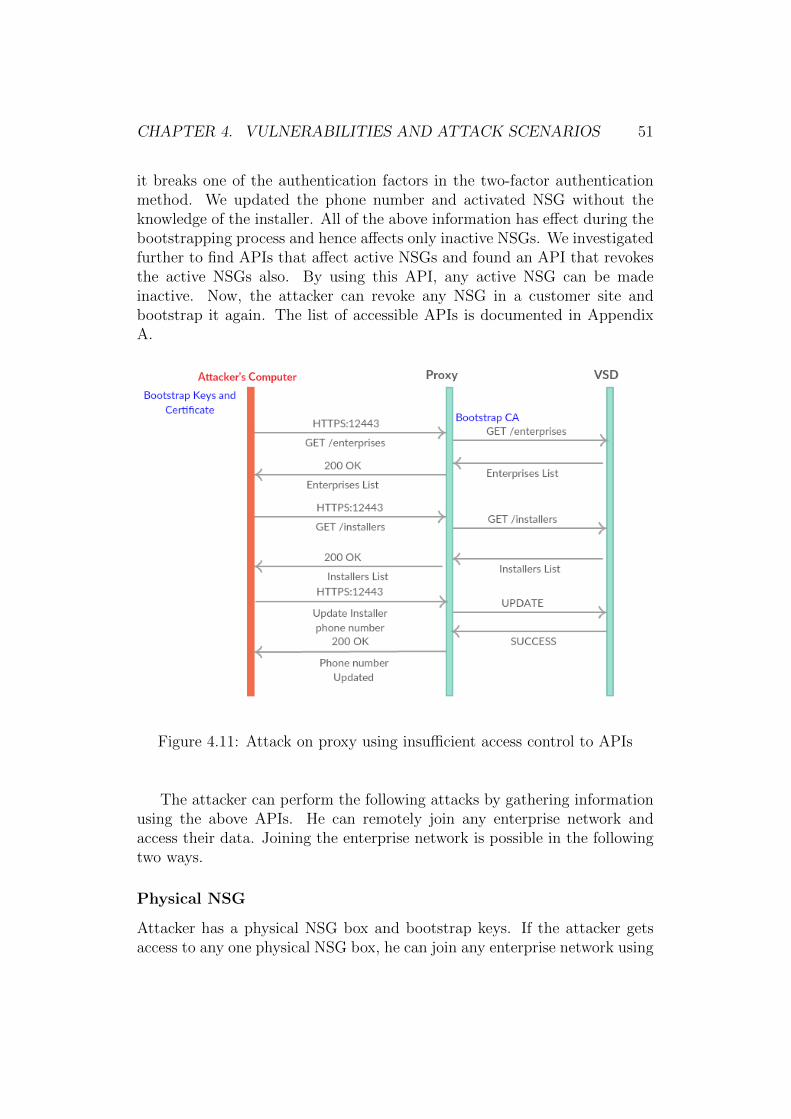
CHAPTER 4. VULNERABILITIES AND ATTACK SCENARIOS 51
it breaks one of the authentication factors in the two-factor authenticationmethod. We updated the phone number and activated NSG without theknowledge of the installer. All of the above information has effect during thebootstrapping process and hence affects only inactive NSGs. We investigatedfurther to find APIs that affect active NSGs and found an API that revokesthe active NSGs also. By using this API, any active NSG can be madeinactive. Now, the attacker can revoke any NSG in a customer site andbootstrap it again. The list of accessible APIs is documented in AppendixA.
Figure 4.11: Attack on proxy using insufficient access control to APIs
The attacker can perform the following attacks by gathering informationusing the above APIs. He can remotely join any enterprise network andaccess their data. Joining the enterprise network is possible in the followingtwo ways.
Physical NSG
Attacker has a physical NSG box and bootstrap keys. If the attacker getsaccess to any one physical NSG box, he can join any enterprise network using
CHAPTER 4. VULNERABILITIES AND ATTACK SCENARIOS 52
the above APIs. The attacker needs to know the UID of any one of the NSGsin the enterprise. In addition, he needs to know the installer mobile numberassociated with that UID. The attacker can get this information by usingthe APIs described above. Once this information is known, the attacker caninitiate the activation of his NSG by composing his own activation e-mail.Through social engineering, as mentioned in Section 4.2.3, the attacker canobtain the activation code from the installer’s mobile. If social engineeringdoes not work, still attacker can continue his attack by updating the in-staller’s phone number with the open API. Now the activation code will besent to the attacker’s mobile phone. Thus, the NSG is authenticated andsubsequently it joins the enterprise network.
We performed the above attack and were successful in joining the en-terprise network with our NSG. The UID used for composing e-mail shouldbe always inactive or else this attack will not be successful. However, wecan make any UID inactive using the revoke API and hence this attack willalways work.
Emulating NSG
Attacker has only the bootstrap keys. If the attacker has no physical NSGdevice, it can emulate an NSG in order to join any enterprise network. Theattacker emulates an NSG and connects to the real proxy where the proxyconsiders it as a real NSG and forwards the request to VSD. The attacker’semulated NSG performs all the bootstrap requests and it is authenticated.The attacker uses the same steps as above to break the two-factor authentica-tion and receives the VSP CA signed certificates. Using the VSP CA signedcertificates, he gets the configuration of NSG including the controller details.Then, he initiates an OpenFlow TLS connection to the Nuage controller andconnects to the respective enterprise network.
We performed this attack using our emulated NSG and successfully es-tablished a connection to Nuage proxy. The emulated NSG is authenticatedand VSP CA signed certificates are received. Using these certificates, we ob-tained the NSG configuration and controller details. The controller detailsinclude its IP address, public key and certificate. We assume that, with thisinformation, it is possible to connect to the controller using Open vSwitch,which has not been verified yet.
In addition, we found that using these VSP CA certificates, we couldobtain the configurations of the other NSGs and access to their information.The possible reason for this behaviour could be lack of access control inVSD, which should restrict NSG’s access to the APIs of other NSGs. Wemitigated this attack by adding access control at the proxy. After adding
CHAPTER 4. VULNERABILITIES AND ATTACK SCENARIOS 53
access control rules, the attacker will not be able to access unwanted APIsbut still he can access APIs that are required during the bootstrapping.Further, access control did not restrict access to other NSGs information,which can be obtained by using any one of the NSG’s VSP CA certificates.
4.3.4 Other attacks
This section describes other attacks that lead to denial of service and confu-sion among the customers. These attacks make use of the bootstrap weak-nesses and the VSD’s access control weaknesses explained in the above sec-tions. We assume that the attacker has access to the NSG bootstrap keys andthe IP address range of NSGs. In this attack, the attacker revokes the NSGin one enterprise and activates it with the UID of another enterprise. Thus,the customer site belonging to one enterprise is connected to a different en-terprise network, which leads to confusion, denial of service, and ultimatelygiving bad name to the service provider. Here, the NSG is revoked using therevoke API and its activation is possible remotely using its public web server,which is explained in Section 4.2.2. The UIDs and the installer details areobtained and updated by the APIs.
DOS attacks are possible even if the attacker has access only to the proxybootstrap keys. NSG is forced to connect to the attacker’s proxy by tamper-ing the activation e-mail or by updating the iptable rules in NSG. Since theattacker’s proxy has proxy bootstrap keys, the connection between NSG andthe proxy will be successful. Now the attacker’s proxy will simply reply tothe NSG’s request and even generates and sends a fake activation code to theinstaller. Then the proxy forces NSG to connect to the fake controller, whichsends false OpenFlow rules. The installer assumes that he is connected tothe real controller and tries to access enterprise data, which is not possible.This creates confusion and denial of service for a while. This attack canbe noticed soon after the installer contacts the operator’s customer centre.Nevertheless, a few hours of confusion will cause bad name to the serviceprovider.
Chapter 5
Discussion
We discussed the attacks and vulnerabilities of Nuage VNS in the previouschapter. In this chapter, we discuss the solutions to mitigate the discoveredattacks. In addition, we also describe the possible designs that could solvethe authentication problem of customer premises equipment. Finally, wepropose the future work that can be carried out to proceed further with thesecurity analysis of SD-WAN.
5.1 Solutions for the attacks
The solutions for the attacks and vulnerabilities are listed in this section, inthe increasing order of criticality.
5.1.1 Minimizing NSG’s attack surface
In order to mitigate the attacks on NSG, we should reduce the NSG’s attacksurfaces. The main attack surfaces are the open SSH and web server port.These two ports are open to the public internet, which leads to the attacks.These two ports should be closed to the internet and should be made ac-cessible only to the user connected to LAN port 3. Thus, only the installercan access the web server and SSH connection. In addition, the default pass-words on the NSGs should be changed before deploying it in the customersite. This can be performed either by the service provider before delivery orby instructing the customer to change the password before deployment. Thisavoids the attacker logging into NSGs and executing commands.
In addition, we should modify the contents of the activation link sentto the installer. The activation link contains information such as installer’sphone number, which could be removed to avoid social engineering attacks.
54
CHAPTER 5. DISCUSSION 55
Further, time validation should be added into the activation link. This pre-vents the attacker from using old activation links for activation. The acti-vation link should also be made invalid if it is used more than once. Theservice provider should be careful in collecting installer details such as e-mailand phone number for bigger customers. Correct installer details should becollected and stored in order to mitigate social engineering attacks.
5.1.2 Replacing the bootstrap CA certificates
Bootstrapping attacks are mainly due to the reuse of the certificates pro-vided by the global bootstrap CA. We can mitigate this attack by replacingthe global bootstrap CA with the service provider’s own bootstrap CA andconfiguring all NSGs and proxies to trust only this service-provider-specificbootstrap CA. This prevents the attacker’s easy access to the bootstrap cer-tificates and related private keys as he needs to access the particular serviceprovider’s proxy and NSG for the keys. Still, if he managed to get thebootstrap certificates from that service provider’s NSG, he can continue theattacks towards the proxy. We can mitigate this further by configuring allNSGs to have individual names, certificates and key pairs for the bootstrapclient. These certificates should also be issued by the service provider’s boot-strap CA. Then, in the backend server (VSD), we can keep a mapping of allthe NSG names and the respective customers.
In addition, the NSG should restrict access to the bootstrap private keysfor the nuage user. This prevents the attackers with SSH access from acquir-ing the bootstrap private keys without having root access to the NSG.
5.1.3 Adding secure access control at the proxy
Adding secure access control at the proxy restricts access to unnecessary APIsof VSD. Currently, the attacker is able to access APIs because of lack of ac-cess control at the proxy. Thus, the proxy machine should be hardened andits configurations should be changed to allow only APIs that are needed dur-ing NSG’s bootstrapping and post-bootstrapping stage. The vendor shouldprovide this list of APIs and configurations for the proxy.
In addition, we need client certificate authentication to avoid access toother NSG information using any one of the NSGs certificates. Client cer-tificate authentication is a common feature in most of the proxies that liebetween the client and backend web server. Usually, the HTTPS connectionfrom the client is terminated at the proxy and the proxy initiates a new con-nection to the backend web server. Since the client connection is terminatedat the proxy, the backend web server does not have information about the
CHAPTER 5. DISCUSSION 56
client and its certificates. However, the backend web server needs to knowthe client identity so that it can perform access control and give permissionto access APIs belonging to that particular client only. For this reason, theproxy receives and parses the client certificate and adds this informationinto one of the HTTP headers sent to the backend server. Now, the backendserver receives the client information so that it can perform the access deci-sion. Different proxies do certificate parsing in different ways. Appendix Bshows the configurations in F5 proxy and Nginx reverse proxy.
We have this problem in the Nuage platform where the proxy lies betweenthe NSG (client) and VSD (backend server). Since there is no certificateparsing happening in the proxy, there is no access validation at VSD, whichenables accessing the configuration information of other NSGs by having acertificate from anyone of the NSG. Thus, we have to add certificate parsingand access control in the proxy and VSD respectively in order to make theAPIs secure. That way, the backend server (VSD) API will have fine-grainedaccess control for the requests based on the authenticated NSG name, thelist of authorized NSGs, and the mapping of NSGs to customers.
If we make all the above changes, then maybe a simpler NSG activa-tion process would be sufficient because most of the configuration would bealready done before shipping the NSG to the customer.
5.2 General discussion
This section discusses the different designs possible for NSG bootstrapping toavoid the authentication problems. The main weakness found in the NuageVNS is the lack of preconfiguration in the NSG before its delivery. Thisresults in security weaknesses, which lead to the above attacks. In order toperform secure bootstrapping, NSG should be configured before delivering itto the customers. Further, we can also use secure hardware authenticationmethods such as TPM for CPE authentication. An overview of TPM and itsusage in CPEs is given in the following section.
5.2.1 TPM
TPM chips should be used in the CPE for authentication. TPM is a computerchip that securely store the artifacts used to authenticate the platform1. Itprovides a hardware based approach for authentication and data protectionthat improves the security to a higher lever than pure software security. TPM
1http://www.trustedcomputinggroup.org/trusted-platform-module-tpm-summary/
CHAPTER 5. DISCUSSION 57
has two RSA key pairs, namely Endorsement Key (EK) and Storage RootKey (SRK). The endorsement key is stored inside the TPM and cannot beaccessed or modified by software. The endorsement key is unique to eachchip. Storage root key is generated by the combination of Endorsement Key(EK) and the master password entered by admin. Thus, the admin takesthe ownership of the hardware. Apart from the admin, no one can accessor modify the hardware. TPM uses advanced cryptographic protocols suchas RSA, SHA-1, and HMAC2. TPM is currently used in laptops, computersand in many types of network equipment for hardware authentication.
TPM can also used be used to generate keys and certificates for TLS au-thentication. Detailed steps for generating keys and certificates are explainedin this blog [20]. We can use this feature of TPM for authenticating a CPEwhich is the NSG in our case. The NSG boxes should be built with the TPMchips having the capability of generating keys and certificates. The installercan claim the ownership of NSG by entering the master password providedby the service provider. This generates unique certificates and keys basedon its Endorsement Key. Now, VSD can authenticate the NSG box basedon these certificates. Since TPM is used, an attacker would not be able toaccess these certificates and keys. Thus, the use of TPM prevents the boot-strapping attacks. In addition, the bootstrapped NSGs cannot be claimed byanyone unless they know the master password. However, the security of themaster password plays an important role and we should securely distributethe master passwords to the installers.
5.3 Future work
In this thesis, we have primarily focused our analysis on the customer premisesequipment, NSG, and its bootstrapping phase. We demonstrated the attackson the NSG’s HTTPS interface. This work needs to continue in the futurewith an analysis of NSG’s OpenFlow interface through which it communi-cates with the controller. This OpenFlow interface is the southbound inter-face of controller where the OpenFlow rules are pushed to the NSG. Further,we should verify the possibility of man-in-the-middle attack in the OpenFlowinterface and intercepting the OpenFlow messages.
We checked the encryption algorithms and the key rotation method usedin the inter-NSG communication. Due to time constraints, we did not spendmuch time in analyzing the proprietary protocol used in that interface. Asa part of the future work, the analysis should continue on these proprietary
2http://www.trustedcomputinggroup.org/trusted-platform-module-tpm-summary/
CHAPTER 5. DISCUSSION 58
protocols in order to find the possible vulnerabilities. In addition, some ofthe controller’s interfaces also needs to be checked. For scaling, the controlleruses the MP-BGP protocol to share information about NSGs. The securityof this interface is not analyzed in this thesis, and the work should be donein the future. Further, the northbound interface of the controller, which isVSD’s API interface, should be analyzed. Extensive testing is required tocheck the correctness of access control at VSD.
As a part of this thesis, we analyzed only one commercial SD-WAN solu-tion, Nuage VNS from Nuage Networks. There are many similar SD-WANsolutions available in the market from many vendors such as Huawei and HP.In the future, we would like to perform a similar security analysis of otherSD-WAN products provided by major vendors. This analysis will give furtherknowledge about the possible attack surfaces and the potential vulnerabilitiesof SD-WAN products in general. This would be helpful in creating generalsecurity guidelines to service providers such as Sonera for providing secureSD-WAN service to their customers.
Chapter 6
Conclusions
SD-WAN transforms the future of enterprise networking by providing a flex-ible and easily manageable network solution to the enterprises. Currently,the enterprises are trying to reduce their operational cost by dropping MPLSlinks, and the service providers are facing problems in providing MPLS withcloudification support. This trend has led to operators considering SD-WANas a better solution for the enterprise. However, the introduction of IP-based SD-WAN will increase the risk of potential attacks on the enterprisenetworks, which are attractive targets for attackers. Hackers are always in-terested in enterprise networks as they contain valuable computing assets anddata. Therefore, both service providers and enterprises consider SD-WAN se-curity as utmost priority, before deploying the new technology widely. In thisthesis, we analyzed one such SD-WAN solution, Nuage VNS, and exposedits attack surfaces and security vulnerabilities and finally demonstrated thepossible attacks on it.
We first studied about the enterprise WAN networks, various solutionsfrom the past, and the concept of SD-WAN. Its advantages over the pastsolutions are explained. Further, we also discussed the need for securityanalysis on SD-WAN and the related literature based on which to performsuch analysis. Chapter 3 introduced the SD-WAN product for our case study,Nuage VNS and described its architecture and operation. Then, we analyzedNuage VNS by investigating its various components and interfaces in detail.As a result, many attack surfaces and security weaknesses were found, es-pecially in the customer premises equipment of Nuage VNS. We also foundvulnerabilities in the CPE bootstrapping method and demonstrated someman-in-the-middle attacks by exploiting those vulnerabilities. Finally, wearticulated the mitigation strategies to avoid the attacks on NSG and pro-posed TPM as a starting point for a more secure design that could solve theauthentication problems.
59
CHAPTER 6. CONCLUSIONS 60
The results of the thesis proved that as expected, many new attack sur-faces and vulnerabilities can be introduced to enterprise network on providingSD-WAN solution. Considering the magnitude of past attacks on enterprisenetworks, attackers would easily exploit these weaknesses and cause damageand loss to the enterprises. Thus, both the vendors and the service providersshould be aware of these vulnerabilities before providing the technology toenterprises. They should also implement suitable countermeasures to mit-igate the attacks as a precautionary step. However, if they ignore thesesecurity weaknesses, many attacks on SD-WAN would be witnessed in thefuture after its wide-scale deployment. We have reported the vulnerabilitiesin Nuage VNS to the vendor and, based on the constructive response, expectthat our work will have a positive effect on the product security.
Bibliography
[1] Bishop, M. About Penetration Testing. IEEE Security Privacy 5, 6(Nov 2007), 84–87.
[2] Brandt, M., Khondoker, R., Marx, R., and Bayarou, K. Secu-rity Analysis of Software-Defined Networking Protocols OpenFlow,OF-Config and OVSDB. In The 2014 IEEE Fifth International Conferenceon Communications and Electronics (ICCE 2014), DA NANG, Vietnam(2014).
[3] Burkholder, P. SSL man-in-the-middle attacks. The SANS Institute(2002).
[4] Callegati, F., Cerroni, W., and Ramilli, M. Man-in-the-MiddleAttack to the HTTPS Protocol. IEEE Security and Privacy 7, 1 (Jan.2009), 78–81.
[5] Chandler, D. Enterprise Networking Solutions Overview, Jul2014. Webpage: http://www.slideshare.net/World_Wide_Technology/
dave-chandler-presents-sdn-at-world-wide-technologys-tecday-st-louis.
[6] Clark, K., Lee, C., Tyree, S., and Hale, J. Guiding ThreatAnalysis with Threat Source Models. In Information Assurance andSecurity Workshop, 2007. IAW ’07. IEEE SMC (June 2007), pp. 262–269.
[7] Dhawan, M., Poddar, R., Mahajan, K., and Mann, V. SPHINX:Detecting Security Attacks in Software-Defined Networks. In 22nd An-nual Network and Distributed System Security Symposium, NDSS 2015,San Diego, California, USA, February 8-11, 2015 (2015), The InternetSociety.
[8] Durumeric, Z., Kasten, J., Bailey, M., and Halderman, J. A.Analysis of the HTTPS certificate ecosystem. In Proceedings of the 2013
61
BIBLIOGRAPHY 62
conference on Internet measurement conference (2013), ACM, pp. 291–304.
[9] Geer, D., and Harthorne, J. Penetration testing: a duet. In Com-puter Security Applications Conference, 2002. Proceedings. 18th Annual(2002), pp. 185–195.
[10] Gottlieb, A. A Brief History of the Enterprise WAN, Apr 2012. Web-page: http://www.networkworld.com/article/2222089/cisco-subnet/
a-brief-history-of-the-enterprise-wan.html.
[11] Gottlieb, A. Why does MPLS cost so much morethan Internet connectivity?, Apr 2012. Webpage: http:
//www.networkworld.com/article/2222196/cisco-subnet/
why-does-mpls-cost-so-much-more-than-internet-connectivity-.
html.
[12] Hogg, S. SDN Security Attack Vectors and SDN Hardening, Oct2014. Webpage: http://www.networkworld.com/article/2840273/sdn/
sdn-security-attack-vectors-and-sdn-hardening.html.
[13] Jorm, D. SDN and Security, Apr 2015. Webpage: http://
onosproject.org/2015/04/03/sdn-and-security-david-jorm/.
[14] Juniper Networks. Understanding Multiprotocol BGP, Feb 2014.Webpage: http://www.juniper.net/documentation/en_US/junos15.
1/topics/usage-guidelines/routing-enabling-multiprotocol-bgp.
html. Accessed Feb 2014.
[15] Juniper Networks. Network Virtual Evolution: Delivering BusinessValue, Sep 2015. Webpage: http://andicom.co/wp-content/uploads/
2015/09/CLAdirect-Network-Virtual-Evolution-v_Final-150901.
compressed.pdf.
[16] Kloti, R., Kotronis, V., and Smith, P. OpenFlow: A securityanalysis. In 2013 21st IEEE International Conference on Network Pro-tocols (ICNP) (Oct 2013), pp. 1–6.
[17] Kourlas, T. Carrier SDN vs Overlay SDN: Duel or Duality?, Oct2015. Webpage: https://www.sdxcentral.com/articles/contributed/
carrier-sdn-vs-overlay-sdn-tony-kourlas/2015/10/.
BIBLIOGRAPHY 63
[18] Kreutz, D., Ramos, F. M. V., Verıssimo, P. E., Rothenberg,C. E., Azodolmolky, S., and Uhlig, S. Software-Defined Net-working: A Comprehensive Survey. Proceedings of the IEEE 103, 1(Jan 2015), 14–76.
[19] Manadhata, P. K., Tan, K. M., Maxion, R. A., and Wing,J. M. An approach to measuring a system’s attack surface. Tech. rep.,DTIC Document, 2007.
[20] Mavrogiannopoulos, N. Using the Trusted Platform Module toprotect your keys, Aug, 2012. Webpage: http://nmav.gnutls.org/2012/08/using-trusted-platform-module-to.html. Accessed Aug 2015.
[21] McCouch, B. SDN, Network Virtualization, and NFV in a nutshell,Sep 2014. Webpage: http://www.networkcomputing.com/networking/
sdn-network-virtualization-and-nfv-nutshell/1655674152.
[22] McGillicuddy, S. SDN security issues: How secure is the SDN stack?,2014. Webpage: http://searchsdn.techtarget.com/news/2240214438/
SDN-security-issues-How-secure-is-the-SDN-stack?src=itke+disc.Accessed Aug 2014.
[23] Mulliner, C., Borgaonkar, R., Stewin, P., and Seifert, J.-P. SMS-based one-time passwords: attacks and defense. In Detection ofIntrusions and Malware, and Vulnerability Assessment. Springer, 2013,pp. 150–159.
[24] Nastech Inc. MPLS data network setup, 2015. Webpage: http:
//www.nastechgroup.com/our-services/mpls-data-network-setup/.
[25] Nuage Networks. Extensible Wide Area Networking, 2016.Whitepaper: http://www.nuagenetworks.net/wp-content/uploads/
2015/04/PR1503009766_NN_VNS_Extensible_Wide_Area-Networking_
Brochure.pdf.
[26] Nuage Networks. Virtualized Services Platform, Nov 2014.Webpage: http://www.nuagenetworks.net/wp-content/uploads/
2014/11MKT2014097652EN_NN_VSP_Virtualized_Services_Platform_R3_
Datasheet.pdf.
[27] ONUG SD-WAN Working Group. ONUG SoftwareDefined WAN Use Case, Oct 2014. Whitepaper: https:
//opennetworkingusergroup.com/wp-content/uploads/2015/05/
ONUG-SD-WAN-WG-Whitepaper_Final1.pdf.
BIBLIOGRAPHY 64
[28] PacketStorm Communications Inc. Enterprise Applications, 2014.Webpage: http://packetstorm.com/enterprise-testing/.
[29] Positive Technologies. Signaling System 7 (SS7) security report,Dec 2014. Whitepaper: https://www.ptsecurity.com/upload/ptcom/
SS7_WP_A4.ENG.0036.01.DEC.28.2014.pdf.
[30] Sandhu, R. S., and Samarati, P. Access control: principle andpractice. IEEE Communications Magazine 32, 9 (Sept 1994), 40–48.
[31] Schehlmann, L., Abt, S., and Baier, H. Blessing or curse? Re-visiting security aspects of Software-Defined Networking. In 10th Inter-national Conference on Network and Service Management (CNSM) andWorkshop (Nov 2014), pp. 382–387.
[32] Scott-Hayward, S., Natarajan, S., and Sezer, S. A Survey ofSecurity in Software Defined Networks. IEEE Communications SurveysTutorials 18, 1 (Firstquarter 2016), 623–654.
[33] Scott-Hayward, S., O’Callaghan, G., and Sezer, S. SDN se-curity: A survey. In Future Networks and Services (SDN4FNS), 2013IEEE SDN For (2013), IEEE, pp. 1–7.
[34] Shin, S., and Gu, G. Attacking Software-Defined Networks: A FirstFeasibility Study. In Proceedings of the Second ACM SIGCOMM Work-shop on Hot Topics in Software Defined Networking (New York, NY,USA, 2013), HotSDN ’13, ACM, pp. 165–166.
[35] Soy, S. The case study as a research method, Apr 1997. Webpage:https://www.ischool.utexas.edu/~ssoy/usesusers/l391d1b.htm.
[36] Thrower, W., and Bhattacharya, S. Threat analysis, May 5 2009.US Patent 7,530,104.
[37] Wang, L., Wong, E., and Xu, D. A Threat Model Driven Approachfor Security Testing. In Software Engineering for Secure Systems, 2007.SESS ’07: ICSE Workshops 2007. Third International Workshop on(May 2007), pp. 10–10.
[38] Yan, Q., Yu, F. R., Gong, Q., and Li, J. Software-defined net-working (SDN) and distributed denial of service (DDoS) attacks in cloudcomputing environments: A survey, some research issues, and chal-lenges. IEEE Communications Surveys Tutorials 18, 1 (Firstquarter2016), 602–622.

BIBLIOGRAPHY 65
[39] Yuan, E., and Tong, J. Attributed based access control (ABAC)for web services. In Web Services, 2005. ICWS 2005. Proceedings. 2005IEEE International Conference on (2005), IEEE.
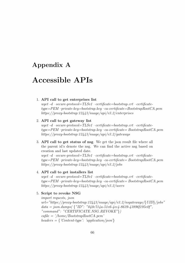
Appendix A
Accessible APIs
1. API call to get enterprises listwget -d –secure-protocol=TLSv1 –certificate=bootstrap.crt –certificate-type=PEM –private-key=bootstrap.key –ca-certificate=BootstrapRootCA.pemhttps://proxy-bootstrap:12443/nuage/api/v3 2/enterprises
2. API call to get gateway listwget -d –secure-protocol=TLSv1 –certificate=bootstrap.crt –certificate-type=PEM –private-key=bootstrap.key –ca-certificate= BootstrapRootCA.pemhttps://proxy-bootstrap:12443/nuage/api/v3 2/gateways
3. API call to get status of nsg. We get the json result file where allthe parent id’s denote the nsg. We can find the active nsg based oncreation and last updated date.wget -d –secure-protocol=TLSv1 –certificate=bootstrap.crt –certificate-type=PEM –private-key=bootstrap.key –ca-certificate= BootstrapRootCA.pemhttps://proxy-bootstrap:12443/nuage/api/v3 2/jobs
4. API call to get installers listwget -d –secure-protocol=TLSv1 –certificate=bootstrap.crt –certificate-type=PEM –private-key=bootstrap.key –ca-certificate= BootstrapRootCA.pemhttps://proxy-bootstrap:12443/nuage/api/v3 2/users
5. Script to revoke NSGimport requests, jsonurl=”https://proxy-bootstrap:12443/nuage/api/v3 2/nsgateways/{UID}/jobs”data = json.dumps( {”ID”: ”040c714a-51e6-4ec4-8639-43896f195e0f”,”command”: ”CERTIFICATE NSG REVOKE”})cafile = ’/home/BootstrapRootCA.pem’headers = {’Content-type’: ’application/json’}
66

APPENDIX A. ACCESSIBLE APIS 67
r = requests.post(url, data,headers=headers , verify=cafile,cert=(’bootstrap.crt’, ’bootstrap.key’))
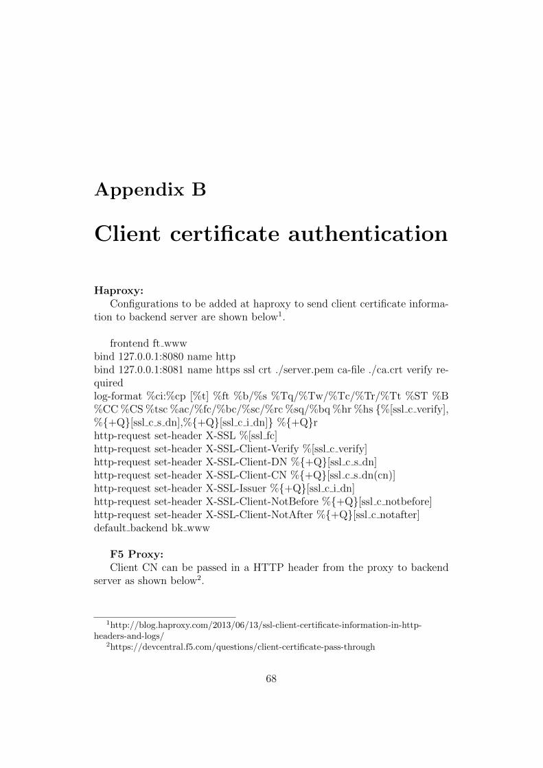
Appendix B
Client certificate authentication
Haproxy:Configurations to be added at haproxy to send client certificate informa-
tion to backend server are shown below1.
frontend ft wwwbind 127.0.0.1:8080 name httpbind 127.0.0.1:8081 name https ssl crt ./server.pem ca-file ./ca.crt verify re-quiredlog-format %ci:%cp [%t] %ft %b/%s %Tq/%Tw/%Tc/%Tr/%Tt %ST %B%CC %CS %tsc %ac/%fc/%bc/%sc/%rc %sq/%bq %hr %hs {%[ssl c verify],%{+Q}[ssl c s dn],%{+Q}[ssl c i dn]} %{+Q}rhttp-request set-header X-SSL %[ssl fc]http-request set-header X-SSL-Client-Verify %[ssl c verify]http-request set-header X-SSL-Client-DN %{+Q}[ssl c s dn]http-request set-header X-SSL-Client-CN %{+Q}[ssl c s dn(cn)]http-request set-header X-SSL-Issuer %{+Q}[ssl c i dn]http-request set-header X-SSL-Client-NotBefore %{+Q}[ssl c notbefore]http-request set-header X-SSL-Client-NotAfter %{+Q}[ssl c notafter]default backend bk www
F5 Proxy:Client CN can be passed in a HTTP header from the proxy to backend
server as shown below2.
1http://blog.haproxy.com/2013/06/13/ssl-client-certificate-information-in-http-headers-and-logs/
2https://devcentral.f5.com/questions/client-certificate-pass-through
68
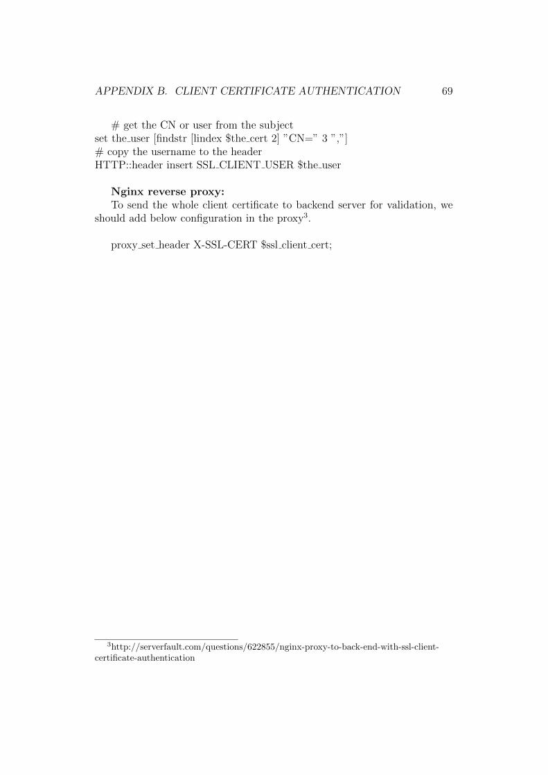
APPENDIX B. CLIENT CERTIFICATE AUTHENTICATION 69
# get the CN or user from the subjectset the user [findstr [lindex $the cert 2] ”CN=” 3 ”,”]# copy the username to the headerHTTP::header insert SSL CLIENT USER $the user
Nginx reverse proxy:To send the whole client certificate to backend server for validation, we
should add below configuration in the proxy3.
proxy set header X-SSL-CERT $ssl client cert;
3http://serverfault.com/questions/622855/nginx-proxy-to-back-end-with-ssl-client-certificate-authentication
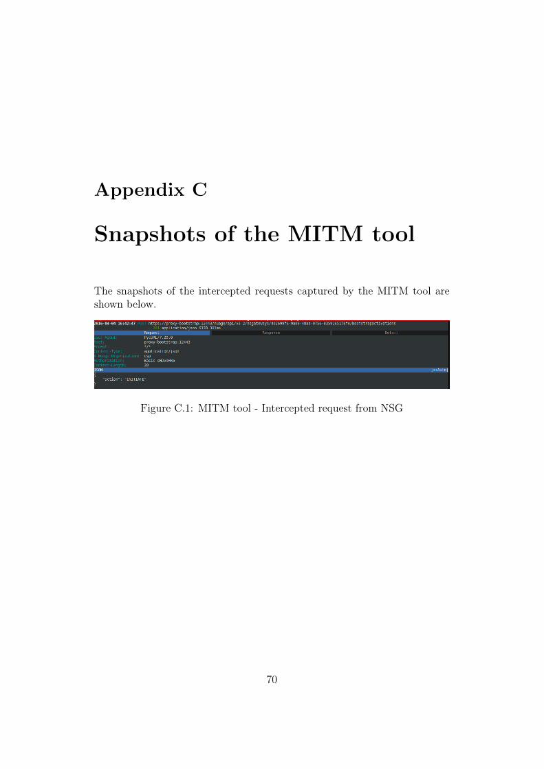
Appendix C
Snapshots of the MITM tool
The snapshots of the intercepted requests captured by the MITM tool areshown below.
Figure C.1: MITM tool - Intercepted request from NSG
70
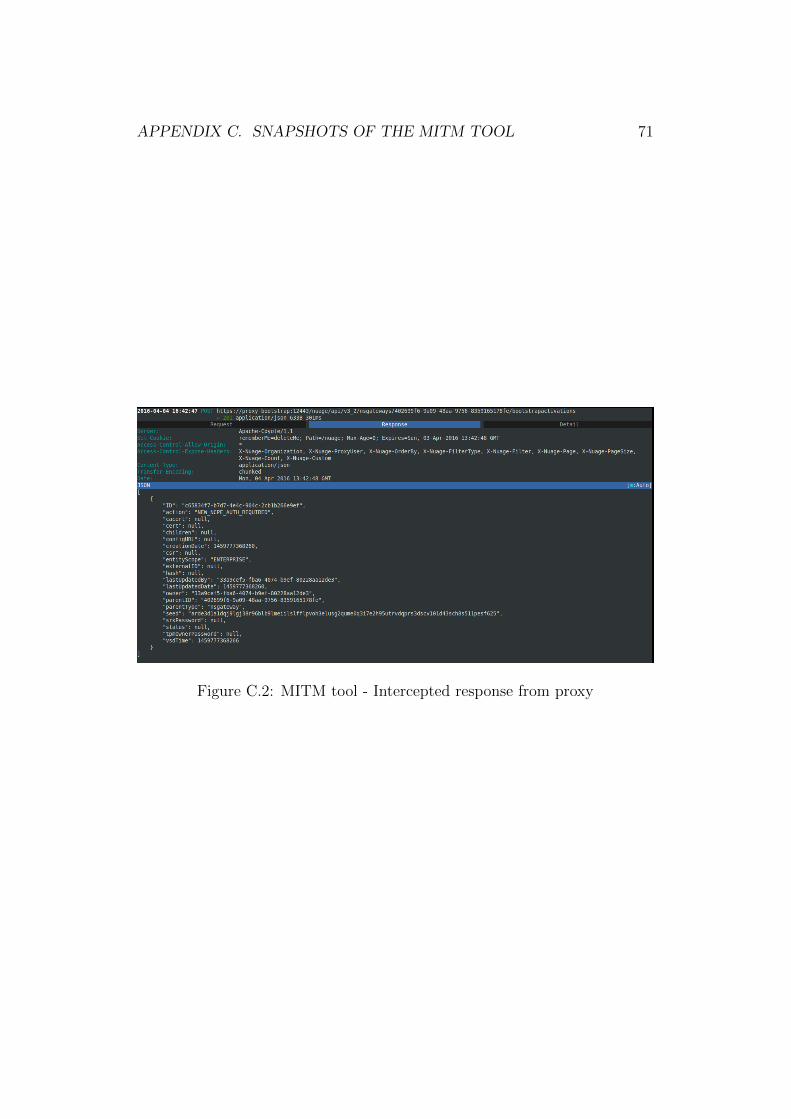
APPENDIX C. SNAPSHOTS OF THE MITM TOOL 71
Figure C.2: MITM tool - Intercepted response from proxy

TRITA TRITA-ICT-EX-2016:116
www.kth.se